Lexus ES300 (2002 year). Service manual - part 17
167
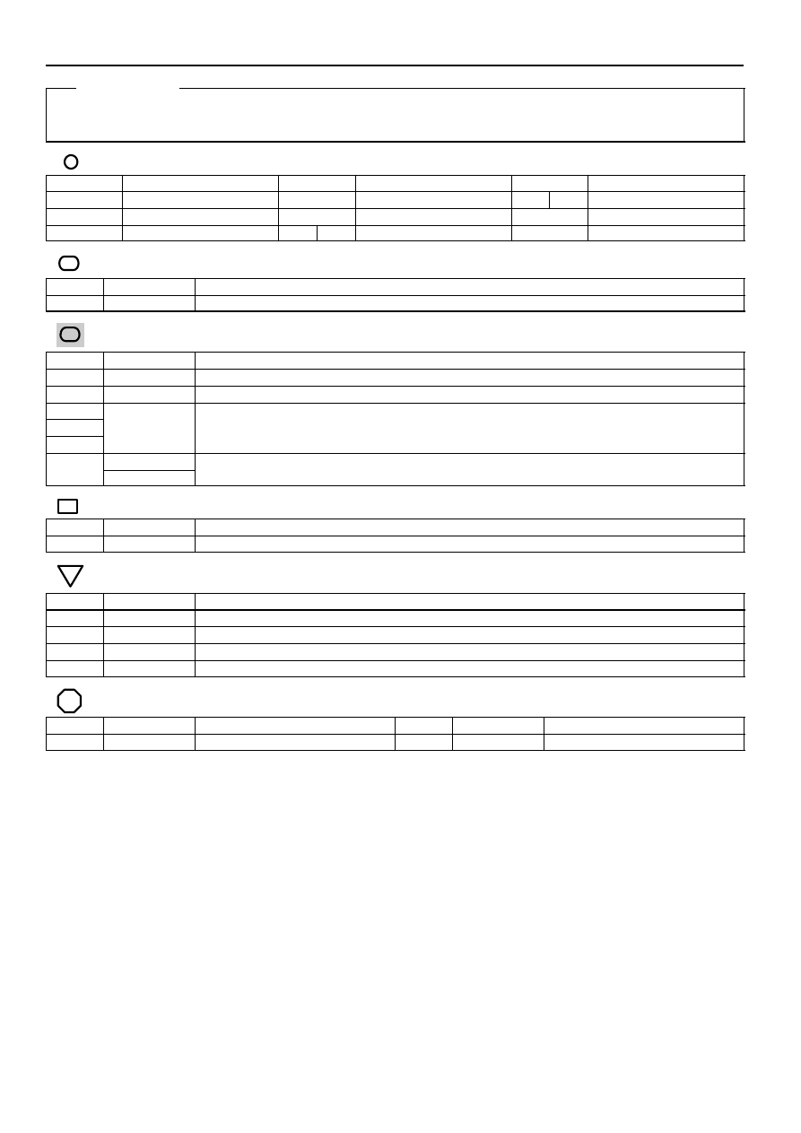
FOG Relay
5–3 : Closed with the light control SW at HEAD position, dimmer SW at LOW position and fog SW on
: Parts Location
Code
See Page
Code
See Page
Code
See Page
C7
F2
J9
B
C11
J4
F1
J8
A
: Relay Blocks
Code
See Page
Relay Blocks (Relay Block Location)
1
Engine Room R/B (Engine Compartment Left)
: Junction Block and Wire Harness Connector
Code
See Page
Junction Block and Wire Harness (Connector Location)
2C
Instrument Panel Wire and Driver Side J/B (Lower Finish Panel)
2G
Engine Room Main Wire and Driver Side J/B (Lower Finish Panel)
2M
2O
Instrument Panel Wire and Driver Side J/B (Lower Finish Panel)
2R
(
)
3A
Instrument Panel Wire and Passenger Side J/B (Instrument Panel Brace RH)
3A
Instrument Panel Wire and Passenger Side J/B (Instrument Panel Brace RH)
: Connector Joining Wire Harness and Wire Harness
Code
See Page
Joining Wire Harness and Wire Harness (Connector Location)
IF5
Engine Room Main Wire and Instrument Panel Wire (Right Side of Steering Column Tube)
: Ground Points
Code
See Page
Ground Points Location
EB
Right Fender
EC
Left Fender
IA
Instrument Panel Reinforcement LH
IB
Instrument Panel Brace LH
: Splice Points
Code
See Page
Wire Harness with Splice Points
Code
See Page
Wire Harness with Splice Points
I2
Engine Room Main Wire
Service Hints