Lexus ES300 (2002 year). Service manual - part 15


  Index      Lexus     Lexus ES300 - service and repair manual 2002 year


Search            


Content   ..  13  14  15  16   ..


Lexus ES300 (2002 year). Service manual - part 15


159

2

3

1

2

2

1

1

2

IA

2M

8

2R

8

G

G

G

W–

G

W–

G

Cl

o

c

k

C 6

A

/T

 S

h

ift

 Lev

er

Illu

m

in

a

tio

n

A2

0

G

lov

B

o

x L

ight S

W

G 3

C

ons

o

le B

o

x

 I

llu

m

inat

io

n

C1

2

II1

7

II1

9

SB

W–

B

1

3

C

igar

ett

e

 Li

gh

ter

Illu

m

in

a

tio

n

C 5

R

adi

and

 P

lay

er

R 2

(A

)

IH1

8

9

IH1

3A

33

3A

43

3A

65

3A

115

3A

64

3A

14

3A

55

3A

85

3A

63

3A

17

3A

48

3A

68

3A

118

3A

98

3A

19

3A

88

W–

G

W–

B

G

G

W–

G

W–

B

SB

W–

G

G

G

G

W–

B

W–

G

W–G

SB

W

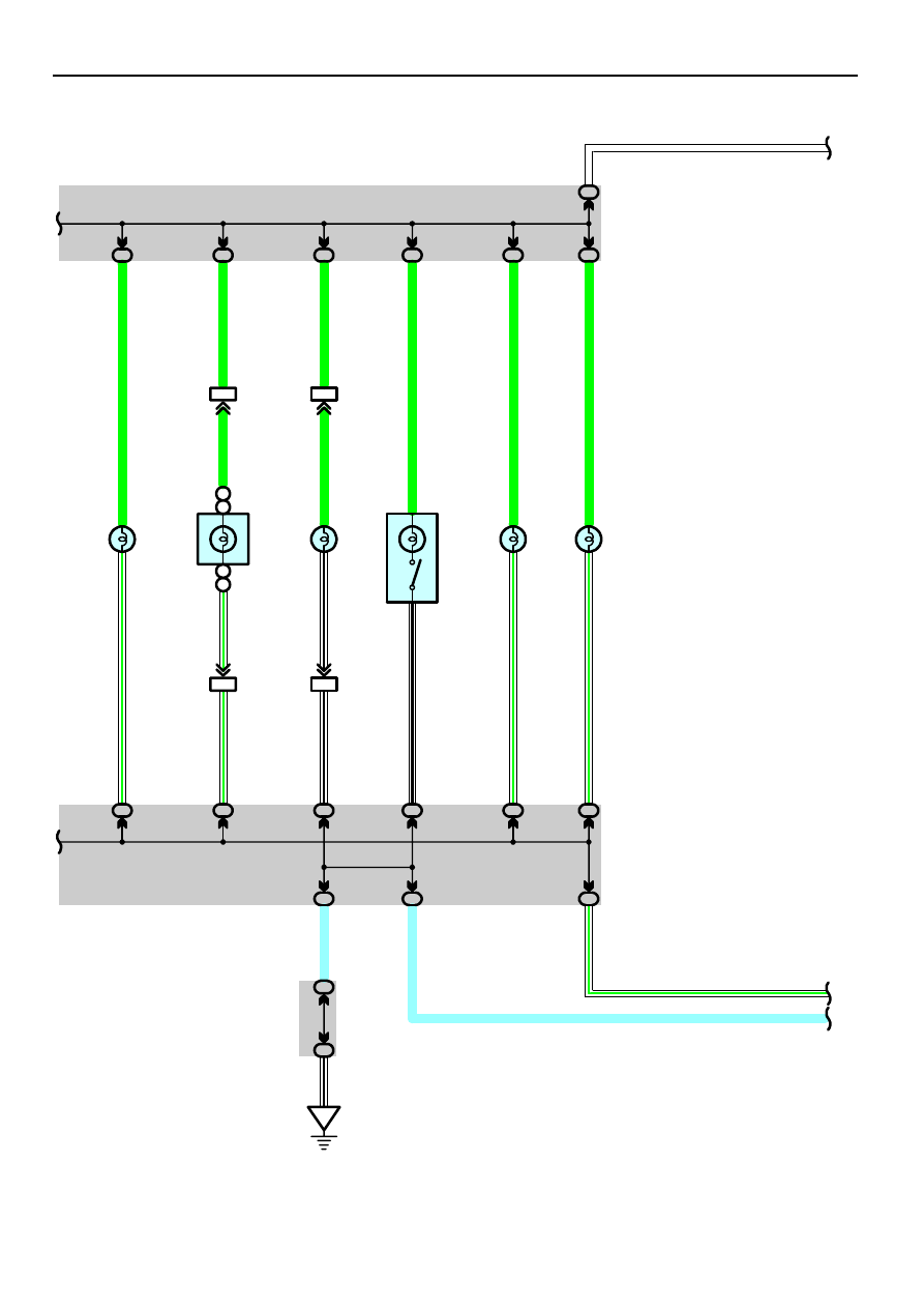
*  1 : w/ LEXUS Navigation System
*  2 : w/o LEXUS Navigation System

A

2

(*2)

D

2

(*1)

D

12

A

12

(*2)

(*1)

R

adi

o and

 P

lay

er

 w

it

h

 D

is

p

la

y

R 6

(D

)

160

Illumination

A

20

A

40

A

19

B

1

B

3

B

19

B

24

A

1

A

21

Micro Computer

Power

10A
ECU–B

From Power Source System (See Page 56)

2M

6

3B

84

3B

64

3B

54

3B

74

3A

86

3A

87

3A

56

3A

57

10A
GAUGE1

2M

1

ID

W–G

SB

W

W

W

W

G

W–

G

GR

B

W–

G

SB

W

BR

BR

W

W

Rheostat

R 9

(*3)
(*4)

(*3)
(*4)

Combination Meter

C 7(A), C 8(B)

3

1

4

* 3 : w/ VSC
* 4 : w/o VSC

Illu

m

in

a

tio

n

Illu

m

in

a

tio

n

Illu

m

in

a

tio

n

T

TC

RV

161

TAIL Relay

5–3 : Closed with the light control SW at TAIL or HEAD position

C11  Combination SW

14–16 : Closed with the light control SW at TAIL or HEAD position

  :  Parts Location

Code

See Page

Code

See Page

Code

See Page

A14

38

C8

B

38

R2

A

39

A20

38

C11

38

R6

D

39

A23

38

C12

38

R7

39

B4

A

38

G3

39

R8

39

C5

38

H13

39

R9

39

C6

38

J3

39

C7

A

38

J4

39

: Relay Blocks

Code

See Page

Relay Blocks (Relay Block Location)

1

22

Engine Room R/B (Engine Compartment Left)

: Junction Block and Wire Harness Connector

Code

See Page

Junction Block and Wire Harness (Connector Location)

2E

28

Engine Room Main Wire and Driver Side J/B (Lower Finish Panel)

2M

29

Instrument Panel Wire and Driver Side J/B (Lower Finish Panel)

2R

29

Instrument Panel Wire and Driver Side J/B (Lower Finish Panel)

3A

34 (w/ VSC)

3A

35 (w/o VSC)

Instrument Panel Wire and Passenger Side J/B (Instrument Panel Brace RH)

3B

34 (w/ VSC)

Instrument Panel Wire and Passenger Side J/B (Instrument Panel Brace RH)

3B

35 (w/o VSC)

: Connector Joining Wire Harness and Wire Harness

Code

See Page

Joining Wire Harness and Wire Harness (Connector Location)

IH1

48

Instrument Panel Wire and Instrument Panel No.4 Wire (Behind the A/C Control Assembly)

II1

48

Instrument Panel Wire and Instrument Panel No.2 Wire (Behind the A/C Control Assembly)

: Ground Points

Code

See Page

Ground Points Location

IA

46

Instrument Panel Reinforcement LH

IB

46

Instrument Panel Brace LH

ID

46

Instrument Panel Brace RH

Service Hints

162

Turn Signal and Hazard Warning Light

10A
GAUGE1

From Power Source System (See Page 56)

2M

1

3A

57

15A
HAZ

1B

1

3A

77

IF7

8

2N

1

2N

2

2G

2

2K

20

2G

4

2K

8

2

1

2

1

IA

EB

BE

IB

LH

Off

RH

Tu

rn

 S

W

LG–B

W

W

R–

L

W

LG

B

G–

Y

G–

B

G–

Y

G–

W

G–

B

G–

B

SB

SB

G–

Y

G–

Y

W–

B

W–

B

W–

B

W–

B

W–

B

W–

B

Turn Signal
Flasher Relay

T 9

Junction
Connector

J 1

Re

a

r T

u

rn

S

igna

l Li

g

h

t LH

R2

2

F

ront

 T

u

rn

S

igna

l Li

g

h

t LH

F 5

F

ront

 T

u

rn

S

igna

l Li

g

h

t R

H

F 6

Re

a

r T

u

rn

S

igna

l Li

g

h

t R

H

R2

3

1

4

8

1

3

30

13

A

3

2

5

6

1

A

LL

LR

EL

ER

IG

+B

EHW

Junction
Connector

J 6(A), J 7(B)

2R

1

2R

2

Combination SW

C11

2

7

GND

W–

B

W

B

A

B20

W–

B

W–

B

W–B

IH1

2

1

4

IH1

5

LG

–B

W–

B

W–

B

A

Ha

z

a

rd

 S

W

H1

3

1

1

2

2

Tu

rn

 R

H

Tu

rn

 L

H

3A

55

3A

85

2R

8

2M

8

EC

Junction
Connector

J 4

A

A

SB

SB

W–B

Combination
Meter

C 7

W–

B

SB

A

A

A

A

B

C

10

HAZ

LG–B

Body ECU

B 5


Content   ..  13  14  15  16   ..