Isuzu N-Series. Service manual - part 612


  Index      Isuzu     Isuzu N-Series - service and repair manual


Search            


Content   ..  610  611  612  613   ..


Isuzu N-Series. Service manual - part 612


6C-18 ENGINE FUEL

Caution:

• The spray condition, when judged with a nozzle

tester, is deemed as normal so long as the spray
form is not excessively deformed.

Oil Tight Test (4JG2 Engine)

1. After completion of the adjustment of injection

pressure, wipe off light oil at the tip of the nozzle
with waste.

2. With pressure 1,961 Kpa (20 kg/cm

2

/284 psi) less

than the specified injection pressure applied,
check to see if an oil drop trickles off the tip of the
nozzle within 10 seconds after application of pres-
sure. (There is no problem with the nozzle when oil
gathers at the tip, but does not drop off.)

3. When an oil drop trickles, clean the nozzle thor-

oughly.
Then reassemble it to check for any dropping of oil.
When oil still drops, change it with a new one.

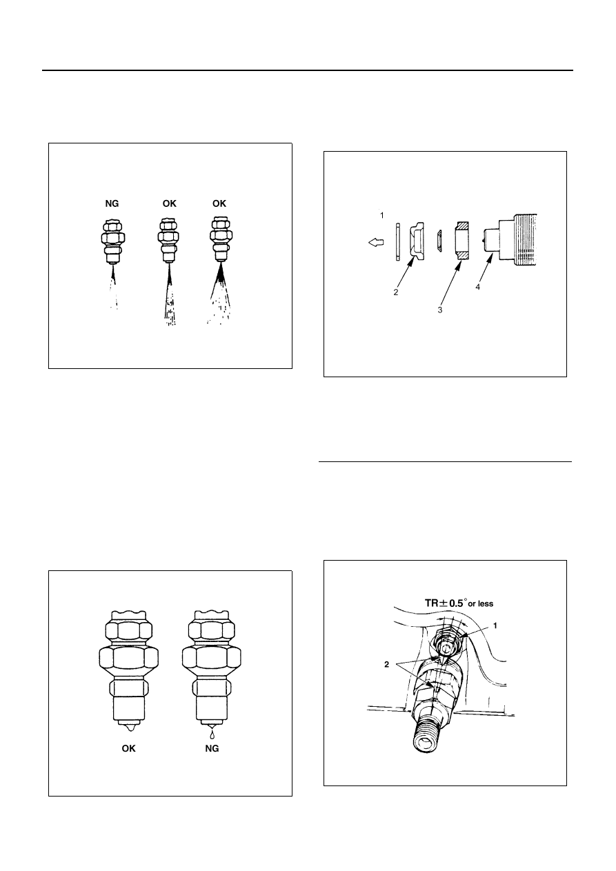
Installation (4JG2 Engine)

Caution:

• Nozzle and assembling should be as illustrated.
• Use new heat shield and new corrugated washer.

1. Injection Nozzle (4JG2 only)

• Lightly tighten the holder nut to suck extent that the

nozzle holder can turn one word and one word.

• Set positioning confirmation drilled hole (

φ2) within

a nozzle turning angle of 

±5° against the cylinder

headside positioning boss.

N6A3747E

N6A3748E

Legend

1. Cylinder head side
2. Nozzle heat shield
3. Gasket heat shield
4. Nozzle

N6A3749E

N6A3072E

ENGINE FUEL 6C-19

• Apply a wrench as illustrated and tighten the holder

nut to the specified torque using a special tool.

Caution:

• After tightening the holder nut, make sure that the

drilled hole makes 

±5° or smaller with the cylinder

head-side positioning boss.

• When mounting leak off pipe, injection nozzle and

pipe, clean with air so that dust may not enter.

Tighten:
Nozzle Fixing Nut to 64 N

⋅m (6.5 kg⋅m/47 lb⋅ft)

Wrench: nozzle holder 5-8840-0259-0

2. Leak Off Pipe

• Mount using a new copper washer.
• Tighten nut to the specified torque.

Tighten:
Pipe Nut to 29 N

⋅m (3.0 kg⋅m/22 lb⋅ft)

3. Injection Pipe

• Connect injection pipe to nozzle holder.
• Tighten the injection pump side.

Tighten:
Sleeve Nut to 29 N

⋅m (3.0 kg⋅m/22 lb⋅ft)

• Fit pipe clip in specified position.

4-1 Injection Nozzle (Two Spring Nozzle Holder)
(4JB1-TC)
The two-spring nozzle holder has been developed to re-
duce NOx (Nitrogen Oxides) and particulates from direct
injection diesel engine exhaust.

Disassembly

1. Retaining nut (1)
2. Nozzle & pin (2)
3. Spacer & pin (3)
4. Lift piece (4)
5. Spring seat (5)
6. Push rod (6)
7. Shim (Second nozzle opening pressure adjust-

ment) (7)

8. Second spring (8)
9. Collar (9)

10. Spring seat (10)
11. First spring (11)
12. Shim (First nozzle opening pressure adjustment)

(12)

13. Nozzle holder body (13)
14. Eye bolt (14)
15. Gasket (15)

1) Before disassembly, remove carbon deposit

from nozzle and nozzle holder using a wire
brush and wash the outside nozzle holder as-
sembly.

Caution:
Do not touch nozzle holes with the wire brush during
cleaning it.

2) Disassemble the nozzle holder assembly to nu-

merical order.

Legend

1. Glow plug
2. Positioning boss

N6A3751E

N6A3402E

6C-20 ENGINE FUEL

Reassembly and Opening Pressure Adjust-
ment (4JB1-TC)

1. Nozzle holder body
2. Shim (First opening pressure adjustment)
3. First spring
4. Spring seat
5. Collar
6. Second spring
7. Push rod
8. Shim (Second opening pressure adjustment)
9. Spring seat

10. Lift piece
11. Spacer & pin
12. Nozzle & pin
13. Retaining nut
14. Gasket
15. Eye bolt

The nozzle holder is adjusted as the components are re-
assembled in the sequence above.
As adjustment of the two-spring nozzle holder is made
in hundredths of a millimeter, clean the parts thoroughly
in light oil to completely remove any dirt or foreign mat-
ter.

N6A3403E

ENGINE FUEL 6C-21

Reassembly and Adjustment Procedure

First Nozzle Opening Pressure Adjustment

1. Claim the nozzle holder in a vise.

2. Install the shim, first spring and spring seat in the

nozzle holder.

3. Install the collar, second spring, shim, spring seat

and push rod in the nozzle holder.

N6A3692E

Legend

1. Nozzle holder body

N6A3404E

Legend

1. Spring seat
2. First spring
3. First nozzle opening pressure adjusting shim

N6A3405E


Content   ..  610  611  612  613   ..