Isuzu N-Series. Service manual - part 613


  Index      Isuzu     Isuzu N-Series - service and repair manual


Search            


Content   ..  611  612  613  614   ..


Isuzu N-Series. Service manual - part 613


6C-22 ENGINE FUEL

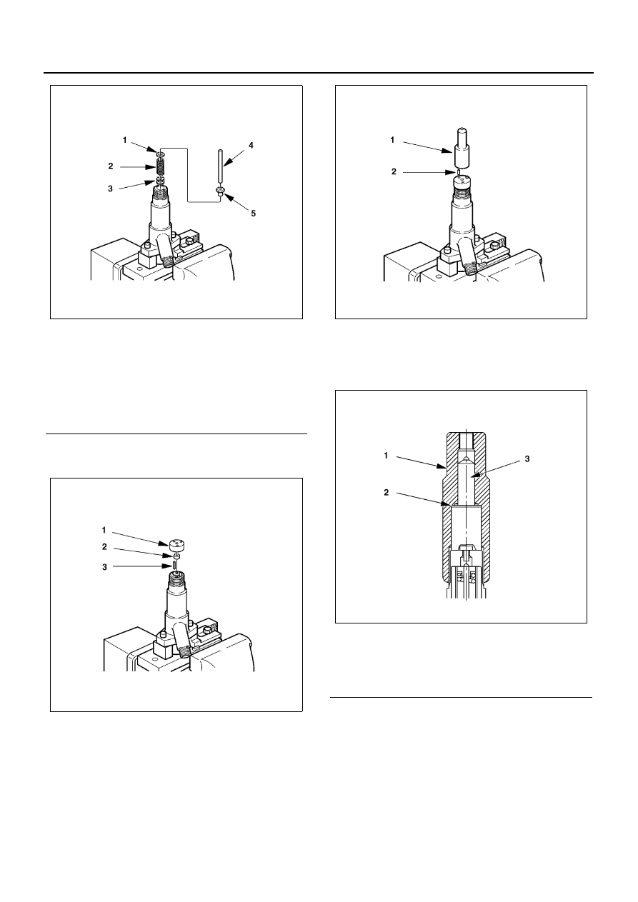
4. Install the pins (3), lift piece (2) and spacer (1) in

the nozzle holder.

5. Install the pins (2) in the spacer.
6. Install the nozzle (1) on the spacer.

7. Hand-tighten the adjustment retaining nut together

with the gasket to the nozzle holder.
Retaining nut: 5-8677-7140-0
Gasket: 5-8677-7139-0

8. Tighten the adjustment retaining nut to the speci-

fied torque.

Tighten:
Retaining nut to 29 — 39 N

⋅m (3.0 — 4.0 kg⋅m)

Legend

1. Second nozzle opening pressure adjusting 

shim

2. Second spring
3. Collar
4. Push rod
5. Spring seat

N6A3406E

N6A3407E

Legend

1. Retaining nut (Special tool)
2. Gasket (Special tool)
3. Nozzle

N6A3408E

N6A3409E

ENGINE FUEL 6C-23

9. Set the nozzle holder to the nozzle tester.

10. Operate the nozzle tester and measure the first

nozzle opening pressure.

11. If the first nozzle opening pressure is not as speci-

fied, disassemble the nozzle holder and replace
the shim until the pressure is as specified.

Caution:
Use a micrometer to measure shim thickness.

• First nozzle opening pressure adjusting shims

Full Needle Valve Lift Confirmation

1. Install the gasket (2) and plug (1) on the adjust-

ment retaining nut.
Gasket: 8-9722-7602-0
Plug: 5-8677-7141-0

Legend

1. Torque wrench
2. Retaining nut (Special tool)

Legend

1. Nozzle holder
2. Nozzle tester

N6A3410E

N6A3411E

Parts No.

Thickness (mm)

1-1534-9042-0

0.40

1-1534-9043-0

0.50

1-1534-9044-0

0.52

1-1534-9045-0

0.54

1-1534-9046-0

0.56

1-1534-9047-0

0.58

1-1534-9048-0

0.60

1-1534-9049-0

0.70

N6A3412E

N6A3413E

6C-24 ENGINE FUEL

2. Position the nozzle holder with the nozzle facing

down and install the dial gauge holder on the noz-
zle holder.
Dial gauge holder: 5-8677-7142-0

3. Install the nut (1) on the dial gauge holder (2).

Nut: 5-8677-7143-0

4. Install the pin (2) to the dial gauge (1).

Notice:
The lengths of the pin do not include the threaded por-
tions.
Pin (liter=100 mm): 5-8677-7144-0
Dial gauge: 1-8531-7015-0

5. Secure the dial gauge to the nozzle holder using

the nut so that the pin contacts the tip of the first
spring seat.

Caution:

• Secure the dial gauge so that a stroke of 2 mm can

be measured.

• Do not over-tighten the nut as the dial gauge shaft

may jam. (Confirm from the dial gauge that the
shaft moves smoothly.)

Legend

1. Dial gauge holder (Special tool)

N6A3414E

N6A3415E

N6A3416E

N6A3417E

ENGINE FUEL 6C-25

6. Set the nozzle holder (1) to the nozzle tester (2)

and put needle to zero on the dial gauge.

7. Operate the nozzle tester (2) to bleed any air from

inside the retaining nut and to confirm that no fuel
leaks.

8. Operate the nozzle tester and increase the inline

pressure to 34.3 — 44.1 MPa (350 — 450 kg/cm

2

)

so that the nozzle’s needle valve moves through its
full lift.
Record full lift ‘L’. (Read dial gauge)

Notice:
The above operation is used to determine whether the
nozzle seat is worn and whether the nozzle assembly is
in good condition.

Pre-lift Confirmation

1. With the needle valve at full lift, release the nozzle

tester handle.

Legend

1. Dial gauge
2. Nut
3. Holder
4. Pin
5. Nozzle holder
6. First spring seat

N6A3411E

Legend

A. Inline pressure

1. Needle valve lift
2. First nozzle opening pressure

Legend

1. Pressure gauge

N6A3419E

N6A3420E


Content   ..  611  612  613  614   ..