Isuzu N-Series. Service manual - part 610
6C-10 ENGINE FUEL
FUEL FILTER CARTRIDGE
Removal
• Remove the cartridge using a filter wrench.
Filter wrench: 5-8840-0253-0 (J-22700)
Installation
• Clean the cartridge mounting surface of filter body
so that the cartridge can be securely.
Apply engine oil thinly to new cartridge O-ring.
• To facilitate bleeding, fill the new cartridge with
light oil.
• Tighten the cartridge until O-ring comes in contact
with the sealing, taking care not to spill the light oil.
• Retighten 1/3 — 2/3 using a filter wrench.
Filter wrench: 5-8840-0253-0 (J-22700)
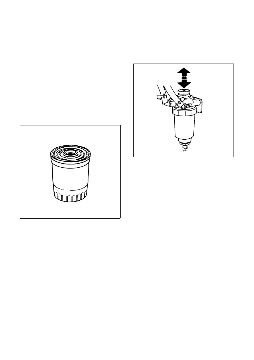
Air Bleeding
• Operate priming pump to send the air in the fuel
system to the injection pump.
• Loosen injection pump bleeding plug, and operate
the priming pump until no bubble is made.
• Tighten the bleeding plug.
• Start the engine, and if it is not started in 10 sec-
onds or less, repeat the bleeding steps.
• Make sure of no fuel leakage, and tighten the prim-
ing pump.
Draining
• When the water in the sedimentor reaches the
specified volume, warning light is actuated.
In this case, follow the draining steps below.
• Set a vinyl hose over the drain plug.
• Loosen the drain plug.
• To drain the water, operate the priming pump sev-
eral times.
• After draining, tighten the drain plug.
• Operate the priming pump several times to check
for fuel leakage.
• Check and see the warning light is off.
N6A3399E
N6A3012E