Isuzu N-Series. Service manual - part 536


  Index      Isuzu     Isuzu N-Series - service and repair manual


Search            


Content   ..  534  535  536  537   ..


Isuzu N-Series. Service manual - part 536


Engine Electrical   6D-11
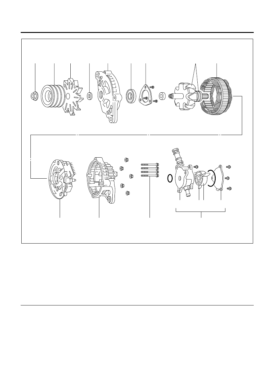
Legend

1. Nut 
2. Pulley 
3. Fan 
4. Spacer 
5. Front Cover 
6. Front Ball Bearing 
7. Bearing Retainer 
8. Rotor and Rear Bearing 
9. Diode Brush Regulator Assembly 

10. Stator 

11. Rear Cover 

12. Through Bolt
13. Housing
14. Vane
15. Pump Rotor
16. Side Plate
17. Vacuum Pump Assembly


Important:

• Separate the stator and rear cover. Be sure you

identify the proper position of the insulated
washers to prevent improper installation.

Inspection

• All metal parts except the voltage rectifier bridge,

stator, rotor and bearing assemblies in a suitable
solvent.

• Wipe or blow the components dry.
• Brush holder and brushes. The brushes have a

line that indicates their limit. If the brushes are
shorter than 6.5 mm (0.256 in) replace the
brushes.

1

9

11

12

13

14 15

16

2

3

4

5

6

7

8

10

17

N6A6594E

6D-12   Engine Electrical

Legend

1. Brush Holder 
2. Brushes

• Voltage regulator for damage or corrosion.
• Bearings and spacer. Rotate the bearing and

check for roughness or excessive drag. If in doubt
about the bearing, replace it.

• Rotor and stator windings for burned insulation or

broken terminal connectors, wires, etc.
Burned insulation may appear as very dark or
blackened wiring, and sometimes charred paint or
a combination of the two. Replace the rotor or
stator if the windings are burned.

• Generator frames. Check for distortion, cracks or

damage. Replace as necessary.

• Rotor slip rings. If the rings are dirty, clean them

with 500–600 grain or finer polishing cloth.
Clean the slip rings with rubbing alcohol if the rings
are contaminated. Spin the rotor and hold the
polishing cloth against the rings until they are
clean. Slip rings which are rough, scored, or out-of-
round, must be machined in a lathe to 31.7 mm
(1.248 in). Finish the slip rings with 500 – 600 grain
or finer polishing cloth and blow away all dust
particles after the machining process.

• All vacuum pump components for wear, damage or

other abnormal conditions.

• Check valve.

1) Carefully force the valve from the “B” side as

shown in the illustration.
The valve must move smoothly.
If it does not, the check valve must be replaced.

2) Apply compressed air to the “A” side.

Check for air leakage from the check valve.
If there is air leakage, the valve must be replaced.

2

1

N6A6595E

Air Pressure

kPa (kg/cm

2

 / psi)

98 – 490 (1 – 5/14 – 71)

slip rings

N6A6596E

Air
Pressure

A

B

N6A6597E

Engine Electrical   6D-13

• Oil seal (O-ring). Check the inner face of the rear

cover for traces of oil leakage. Be sure the inner
face of the oil seal is not worn or damaged.
If worn or damaged, use a screwdriver to remove
the oil seal (O-ring) from the rear cover.
Install a new oil seal (O-ring) using an oil seal
installer or equivalent.

Measure

Replace the housing if not within these specifications.

Electrical Bench Tests (Generator)

1. Measure the rotor coil resistance.

2. Check for continuity between the slip rings and the

rotor core or shaft.
If there is continuity, the entire rotor assembly must
be replaced.

The length of the vanes

mm (in)

17.0 – 18.0 (0.669 – 0.709)

The inside diameter of the vacuum pump
housing

mm (in)

69.5 – 69.6 (2.736 – 2.740)

N6A6407E

N6A6598E

Rotor Coil Resistance at 20

°C (68°F)

ohms

Standard

50A

7.6

60A

9.2

80A

10.2

N6A6599E

slip rings

N6A6600E

6D-14   Engine Electrical

Stator Coil Assembly

1. Check for continuity across the stator coils

If there is no continuity, the stator coils must be
replaced.

2. Check for continuity between each stator coil end

and the stator core.
If there is continuity, the stator coils must be
replaced.

Rectifier

Resistance Between Stator coil neutral
point and the Coil Ends (Reference)

mm (in)

Standard

50A

0.195

60A

0.137

80A

0.073

stator coil

neutral point

stator coil end

N6A6601E

stator coil end

stator core

N6A6602E

N6A6603E

Tester wire

E

+

BAT

+

U, V, and WN

U, V, and WN

+

-----

Conductivity

+

-----

No conductivity

No conductivity

-----

Conductivity

-----

Negative side diode check

Positive side diode check


Content   ..  534  535  536  537   ..