Isuzu N-Series. Service manual - part 537


  Index      Isuzu     Isuzu N-Series - service and repair manual


Search            


Content   ..  535  536  537  538   ..


Isuzu N-Series. Service manual - part 537


Engine Electrical   6D-15
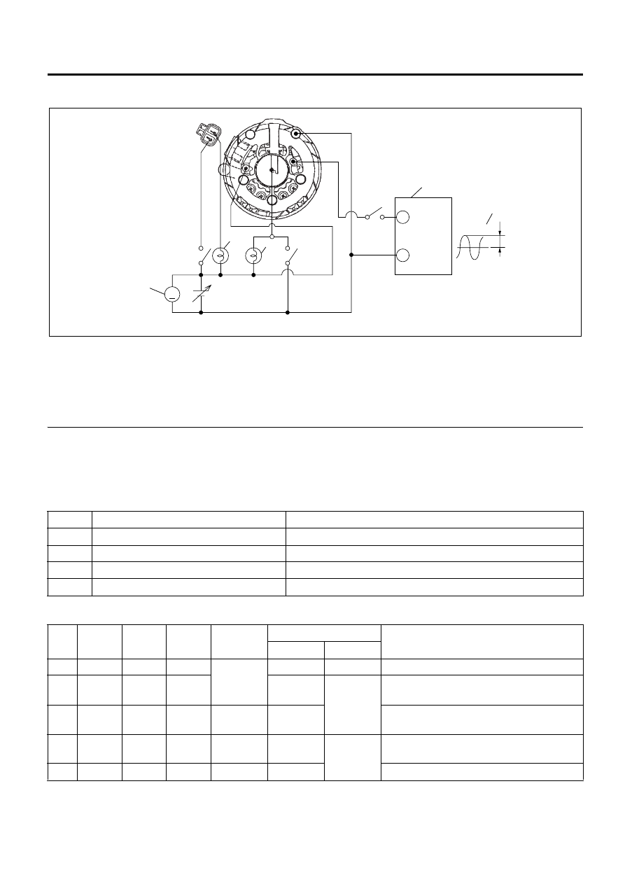
Rectifier Assembly

Legend

1. Voltmeter 
2. Switch 1
3. DC Regulated Power Supply
4. Lamp 2
5. Lamp 1

6. Switch 3
7. Switch 2
8. Pulse Generator
9. Output Signal

Test circuit
Refer to the judgment criteria shown in the Table below.
Carefully check Items 1 

− 5. If all the items are OK, the

IC regulator is normal.
Circuit components

Judgment criteria

V

+

-

5~30V

1kHz

S

L

B

E

P

2

1

3

4

5

6

7

8

9

N6A6604E

1

DC regulated power supply

− 30 volts variable with output of 1 ampere or more

2

Lamps (2)

24 volts, 1.8 watts

3

Switches (3)

-----

4

DC  voltmeter

− 60 volts, 0.5 grade

5

Pulse generator (Oscillator)

− 30 volts output at a frequency of 1kHz

No.

Switch 

1

Switch 

2

Switch 

3

Voltmeter 

reading

Lamp condition

Remarks

Lamp 1

Lamp 2

1

ON

OFF

OFF

24V

On (dim)

ON

Initial excitation check

2

ON

ON

OFF

On or 

flashing

OFF

Full excitation check

3

ON

ON

OFF

32V

Off or 

on (dim)

Lamp 1 off or dimly lit when the voltmeter
shows less than 24 volts or 32 volts

4

OFF

ON

OFF

24V

On or 

flashing

ON

Stator and brush separation check

5

ON

ON

ON

36V

On

Excess voltage check

6D-16   Engine Electrical

Reassembly

Important:

• When connecting the stator coil leads and diode

leads using solder, use long-nose pliers and work
as quickly as possible to prevent the heat from
transferring to the diodes.

1. Stator.
2. Diode brush regulator assembly.
3. Stator and diode brush regulator assembly.
4. Rear cover.
5. Front cover.
6. Front ball bearing.
7. Bearing retainer.
8. Rotor and rear bearing.
9. Spacer.

10. Fan.
11. Pulley.
12. Pulley nut.

Tighten:

Pulley nut (50A) to 98.0 N

⋅m (10 kg⋅m/72.3 lb⋅ft)

Pulley nut (60A, 80A) to 107.8 N

⋅m (11 kg⋅m/79.5 lb⋅ft)

13. Rear cover and stator assembly.

Use a pair of long-nose plier to connect the stator
coil leads and the rectifier leads.
Finish the work as quickly as possible to prevent
the rectifier from heat transferred by the soldering.

Insert the pin from the outside of the rear cover.
Press the brushes into the brush holder. Complete
the assembly procedure.

14. Pulley and rotor assembly.

• Install the pulley and rotor assembly

The rear ball bearing is pressed into the wheel
eccentric groove. The bearing ring projects from
the groove.
During installation, rotate the bearing to the point
of minimum bearing ring projection.

15. Through bolts.

• Place a guide bar through the holes in the front

cover and rear cover flange for proper
alignment. Install the through bolts.

• Remove the tape from the splines.

Tighten:

Through bolts to 4 N

⋅m (0.4 kg⋅m/35 lb⋅in)

16. Vacuum pump assembly.

N6A6605E

Pin

N6A6606E

Projection part
(0.65mm blow) 

Ring

eccentric groove

N6A6607E

Engine Electrical   6D-17

• Position the rotor, with the serrated boss turned

up, on the housing.

Legend

1. Housing 
2. Vane
3. Serrated Boss 
4. Pump Rotor 


• Align the holes in the housing and rotor.
• Install vanes into the slits in pump rotor.

The vanes must be installed with the round side
turned outward.

• After installation of O-ring, install the side plate.

Legend

1. Side Plate
2. Bolt

• Install the vacuum pump assembly to the back

of the generator with 3 screws.

Tighten:

Vacuum pump screws to 7 N

⋅m (0.7 kg⋅m/61 lb⋅in)

• Install 5 cc (0.016 oz) engine oil in the filler port,

then check that the generator pulley can be
turned smoothly by hand.

Installation

1. Generator.

Tighten:

Bracket Mount Bolt to 48 N

⋅m (4.9 kg⋅m/35.4 lb⋅ft)

2. Adjusting bolts.

Tighten:

Adjusting Nut to 24 N

⋅m (2.4 kg⋅m/17 lb⋅ft)

3. Drive belts.

Tighten:

Lower mount bolt to 40 N

⋅m (4.1 kg⋅m/30 lb⋅ft)

4. Vacuum and oil hoses at the vacuum pump.
5. Electrical wiring at the generator.

• Battery negative cable.

6. Install the A/C compressor. (Refer to “Engine

Assembly” in Section 6A.)

1

3

4

2

N6A6608E

1

2

N6A6609E

6D-18   Engine Electrical

Main Data and Specifications

Rated Voltage

24 V

Rated Output

50/60/80 amp

Rated Output at 5000 RPM

More than 42/50/75 amp

Regulated Voltage

28.0 – 29.0 V

Brush Length

Standard

25 mm (0.984 in)

Limit

6.5 mm (0.256 in)

Slip Ring Diameter

Standard

31.7 mm (1.248 in)

Limit

30.6 mm (1.205 in)

Generator Pulley Direction (Viewed From Pulley Side) Clockwise Pulley 

Pulley Diameter

82 mm (3.23 in)

Generator Weight (With Vacuum Pump)

50A: 7.4 kg (16.3 lb)
60A: 9.0 kg (19.8 lb)
80A: 9.6 kg (21.2 lb)

Maximum Vacuum Pump Output

90.7 kPa (0.29 kg/cm

/ 13.2 psi)

Vacuum Pump Vane 

Standard Length

17.0 – 18.0 mm (0.669 – 0.709 in)

Vacuum Pump Housing Inside Diameter 

Standard

69.5 – 69.6 mm (2.736 – 2.740 in)


Content   ..  535  536  537  538   ..