Isuzu N-Series. Service manual - part 530


  Index      Isuzu     Isuzu N-Series - service and repair manual


Search            


Content   ..  528  529  530  531   ..


Isuzu N-Series. Service manual - part 530


6C-28   Fuel System

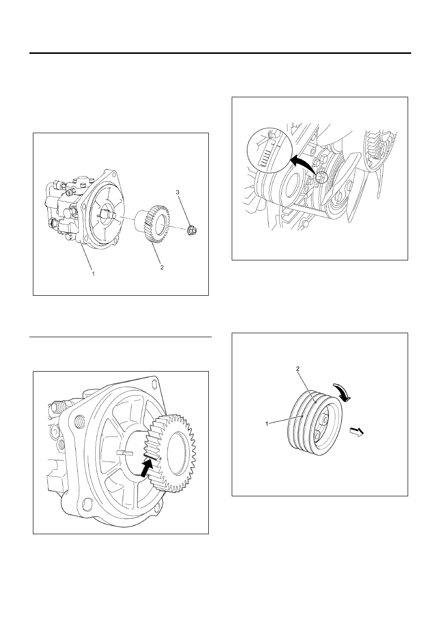
3. Align the fuel supply pump shaft key and gear.

Install the gear and tighten the nut to the specified
torque.
There is a round alignment mark on the gear
(white paint).

Tighten:

Nut to 64 N

⋅m (6.5 kg⋅m/47 lb⋅ft)

Legend

1. Fuel Supply Pump
2. Fuel Supply Gear
3. Nut


4. Apply white paint to the top of the fuel supply pump

gear tooth directly above the stamped ‘O’ mark.
Refer to the illustration.

5. Turn the crankshaft in the normal direction of

engine rotation until the No. 1 or No. 4 cylinder is
at TDC on the compression stroke.
Refer to the illustration.

Notice:
There are 2 timing marks on the crankshaft pulley. 
Mark (1) is near the front cover and is used to bring the
4HK1-TC engine to TDC.
Mark (2) is not applicable to this engine.
Be sure to use mark (1) when bringing the engine to
TDC.

6. Remove the oil drain adapter.
7. Install the O-ring to the fuel supply pump.
8. Align the slits as shown in the illustration.
9. Insert the stud bolts into the guides and

temporarily tighten them.

N6A6378E

N6A6379E

N6A6003E

N6A6002E

Fuel System   6C-29

Caution:

• If the stud bolts (cylinder block side) have been

loosened or replaced, apply Loctite 262 to the
recessed portion of the bolts.

• Check that the round alignment mark (white paint)

is positioned as shown in the illustration when
viewed from the plug hole. If necessary, reposition
the gear.

• Tighten the stud bolts and the nuts to the specified

torque.

Tighten:

Nut to 50 N

⋅m (5.1 kg⋅m/37 lb⋅ft)

Bolt to 76 N

⋅m (7.7 kg⋅m/56 lb⋅ft)

Legend

1. Plug Hole
2. Alignment Mark


10. Apply a light coat of engine oil to the O-ring.

11. Install the oil drain adapter to the plug hole.

Tighten the bolt to the specified torque.

Tighten:

Bolt to 8 N

⋅m (0.8 kg⋅m/69 lb⋅in)

Legend

1. Oil Drain Adapter
2. O-ring


12. Connect the fuel temperature sensor and the

suction control valve connectors to the fuel supply
pump.

13. Install the fuel feed hose.
14. Install the throttle assembly.

• Coat the fluid gasket and mount within 7

minutes.

Tighten:

Throttle assembly to 24 N

⋅m (2.4 kg⋅m/17 lb⋅ft)

• Install the intake throttle valve chamber hose.

Legend

1. Intake Throttle Valve Chamber


15. Install the fuel pipe and fuel leak-off pipe.

N6A6079E

N6A6080E

N6A6081E

N6A6380E

6C-30   Fuel System

Important:
In order to make the fuel supply pump characteristic
learn into the ECM, let the engine idle until warm-up. If
the fuel system DTC’s stored in the meantime, once
clear DTC and warm-up the engine again.

16. Inspect for a proper engine running condition and

for no DTC’s. Refer to the Diagnostic System
Check-Engine Controls if needed.

Torque Specifications

N6A6381E

Fuel System   6C-31

Fuel Rail

Components

Legend

1. Fuel Leak-off Pipe
2. Fuel Pipe
3. EGR Valve
4. EGR Valve Gasket
5. EGR Adapter

6. Injection Pipe Clip
7. Injection Pipe (#1 to #4)
8. Fuel Rail
9. Fuel Rail Bracket


Parts of the fuel system such as the internal part of the
fuel injector, holes and clearances that form passages
for fuel are finished to a very high degree of accuracy.
They are therefore highly sensitive to foreign matter
and the entry of foreign matter could cause damage to
the fuel passage. Therefore, effective measures should
be taken to prevent the entry of foreign matter.

Removal

WARNING:
TO PREVENT LEAKED FUEL FROM CATCHING
FIRE, DO NOT WORK WHILE THE ENGINE IS HOT.

Preparation:

• Pour detergent into a steam cleaner, and throughly

wash around the sensor and the fuel rail.

• Remove water completely using air blow.

N6A6382E


Content   ..  528  529  530  531   ..