Isuzu N-Series. Service manual - part 528


  Index      Isuzu     Isuzu N-Series - service and repair manual


Search            


Content   ..  526  527  528  529   ..


Isuzu N-Series. Service manual - part 528


6C-20   Fuel System

10. Remove the fuel injection pipe clips and the

injection pipes. 

Legend

1. Fuel Injection Pipe
2. Pipe Clip


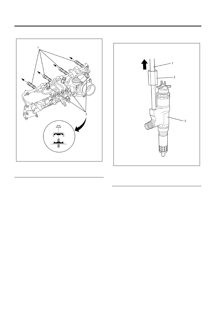
11. Loosen the fuel injector clamp fixing bolts and

remove the fuel injectors.

If the fuel injectors are difficult to remove, use the fuel
injector remover. Install the fuel injector remover to the
leak-off pipe attachment part on the fuel injector. Use a
sliding hammer to force the fuel injector clamp off the
fuel injector.

Caution:
Do not remove the fuel injector sleeve.

Special tools
Fuel injector remover: 5-8840-2826-0 (EN-46720)
Sliding hammer: 5-8840-0019-0 (J-23907)

Legend

1. Sliding Hammer
2. Remover
3. Fuel Injector Assembly


12. Mark each fuel injector with the number of the

cylinder from which it was removed. Store the fuel
injectors in a safe place. Position the fuel injector
so that the nozzle is protected.

Caution:

• Do not tamper with the electromagnetic portion of

the fuel injector. Reduced electromagnetic function
will result in injector failure.

N6A6128E

N6A6129E

Fuel System   6C-21

Recording from the each fuel injector ID plate
Record 24 figures of each fuel injector ID plate. The
correct order for the fuel injector ID code for the
following illustration is as follows:
56 00 D1 CA 00 00 EC 00 23 14 21 B7

Legend

1. Fuel Injector ID Plate
2. Fuel Injector ID Code
3. Fuel Injector


Installation

Important:
Install each of the fuel injectors on its original position.
(the cylinder from which it was removed)

1. Install a new gasket and O-ring to each of the fuel

injector clamps. Refer to the illustration.

Legend

1. Gasket
2. Fuel Injector
3. Bolt
4. Fuel Injector Clamp


2. Apply molybdenum to the threads and seating

surfaces of the clamp bolts.

3. Install the fuel injector clamps to the cylinder head.
4. Temporarily tighten the clamp bolts.
5. Apply a thin coat of engine oil to the outer surface

of the fuel injector side sleeve nuts.

6. Install the fuel injection pipes to the position shown

in the illustration.

7. Use a spanner to carefully the sleeve nuts until the

fuel injection pipes contact the fuel injector and
common rail.

8. Tighten the fuel injection pipe clips to the specified

torque.

Tighten:

Clips to 6 N

⋅m (0.6 kg⋅m/52 lb⋅in)

D1CA

EC00
2100

B7

5600

0000
2314

0000

1

2

3

N6A6524E

N6A6370E

6C-22   Fuel System

Legend

1. Fuel Injection Pipe
1. Pipe Clip


9. Final tighten the injection clamp bolts to the

specified torque.

Tighten:

Bolts to 30 N

⋅m (3.1 kg⋅m/22 lb⋅ft)

10. Tighten the injection pipes to the specified torque.

Tighten:

Injection pipes to 44 N

⋅m (4.5 kg⋅m/33 lb⋅ft)

Legend

1. Clamp Bolt
2. Sleeve Nut


11. Install the nozzle leak-off pipes together with the

new gaskets. Tighten the pipes to the specified
torque.

Tighten:

Pipes to 12 N

⋅m (1.2 kg⋅m/104 lb⋅in)

12. Install the fuel injector harness connectors. Work

from the inside out.

13. Install the harness bracket and tighten the bolts to

the specified torque.

Tighten:

Bolts to 48 N

⋅m (4.9 kg⋅m/35 lb⋅ft)

N6A6128E

N6A6179E

N6A6181E

Fuel System   6C-23

14. Install the fuel injector terminal nuts to the injector.

Tighten:

Nut to 2 N

⋅m (0.2 kg⋅m/17 lb⋅in)

Caution:

• Do not overtighten the nuts. Damage to the

terminal studs will result.

• The terminal nut with two wires is engine front

side.

Legend

1. Fuel Injector
2. Harness
3. Terminal Nut


15. Install the gasket to the cylinder head cover.
16. Install the cylinder head cover and tighten up

according to the order.

Tighten:

Bolts to 18 N

⋅m (1.8 kg⋅m/13 lb⋅ft)

17. Install the sound insulation cover (For Europe).

Tighten:

Bolts to 8 N

⋅m (0.8 kg⋅m/6 lb⋅ft)

Legend

1. Sound Insulation Cover (For Europe)
2. Head Cover

18. Install the gasket to the EGR valve and tighten the

bolts to the specified torque.

Tighten:

Bolts to 24 N

⋅m (2.4 kg⋅m/17 lb⋅ft)

19. Install the gasket to the EGR adapter and tighten

the bolts to the specified torque.

Tighten:

Bolts to 24 N

⋅m (2.4 kg⋅m/17 lb⋅ft)

N6A6182E

2

1

3

N6A6627E

N6A6029E

1

2

N6A6027E


Content   ..  526  527  528  529   ..