Isuzu N-Series. Service manual - part 529
6C-24 Fuel System
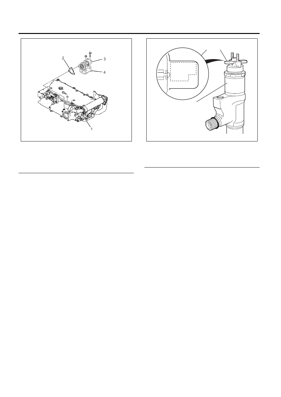
Legend
1. EGR Adapter
2. EGR Valve Gasket
3. EGR Valve
4. EGR Valve Gasket
20. Attach the engine harness connectors. Each
composite connector should make a loud click
when it is securely attached.
Fuel Injector ID Code Data Programming Procedure
1. Install the Tech 2.
2. Turn ON the ignition, with the engine OFF.
3. Select Diagnostics > appropriate vehicle
identification > 4HK1 (Common Rail) >
Programming > Injector ID Code > ID Code
Registration.
4. Select replaced cylinder and press Change. Input
22 figures. Then, input in order from the left edge
of upper sequence to the right sequence. The
correct order for the fuel injector ID code for the
following illustration is as follows:
56 00 D1 CA 00 00 EC 00 23 14 21
Important:
The number of places required for input is 22 figures
except last 2 figures.
Legend
1. Fuel Injector ID Plate
2. Fuel Injector ID Code
3. Fuel Injector
5. After complete the registration, turn OFF the
ignition for 30 second.
6. Turn ON the ignition.
7. Select Diagnostics > appropriate vehicle
identification > 4HK1 (Common Rail) >
Programming > Injector ID Code > Injector ID
Code. At this point, all registered fuel injector ID
code data can be verified. Compare the ID code
values registered into the ECM and each fuel
injector including the last 2 figures. If the registered
ID code is incorrect, go back to Step 4 ID Code
Registration.
8. Start the engine and let idle.
9. Inspect for a proper engine running condition and
for no DTC’s. Refer to the Diagnostic System
Check-Engine Controls if needed.
Notice:
After replacement of the fuel injector, perform the
following procedure.
All fuel injectors are replaced:
Remove the fuel injector ID code label on the cylinder
head cover.
Any fuel injector(s) is replaced:
Blackout the replaced cylinder fuel injector ID code on
the cylinder head cover with a marking pen or
equivalent.
N6A6371E
D1CA
EC00
2100
B7
5600
0000
2314
0000
1
2
3
N6A6525E