Isuzu N-Series. Service manual - part 328


  Index      Isuzu     Isuzu N-Series - service and repair manual


Search            


Content   ..  326  327  328  329   ..


Isuzu N-Series. Service manual - part 328


6A-54 ENGINE MECHANICAL

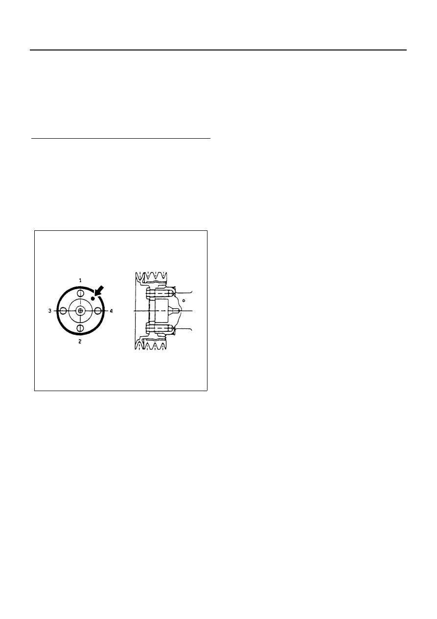
30. Crankshaft Damper Pulley

1) Apply a coat of engine oil to the threads of the

bolts.

2) Align the damper pulley with the crankshaft

knock pin and tighten the bolts to the specified
torque in numerical order.

Tighten:
Damper pulley bolt to 200 N

⋅m (20.4 kg⋅m / 147 lb⋅ft)

31. Generator Bracket
32. Fan Belt Adjust Plate
33. Injection Pump Assembly
34. Engine Foot
35. Generator
36. Fan Belt
37. Fan Belt Adjustment
38. Vacuum Pump Rubber Hose
39. Vacuum Pump Oil Pipe
40. Oil Filter Assembly
41. Oil Pipe
42. Engine Control Lever Assembly
43. Engine Control Wire
44. Driven Plate
45. Clutch Pressure Plate Assembly
46. Cylinder Head Gasket

Above works refer to “CYLINDER BLOCK” section
in this manual.

47. Cylinder Head Assembly

Above works refer to “CYLINDER HEAD” section
in this manual.

Legend

1. Oil seal
2. Adapter
3. Ring
4. Adapter bolt
5. Sleeve
6. Washer (5 mm (0.20 in))
7. Center bolt

N6A0250E

ENGINE MECHANICAL 6A-55

PISTON AND CONNECTING ROD

Component

Disassembly

1. Cylinder Head Assembly

Above works refer to “CYLINDER HEAD” section
in this manual.

2. Cylinder Head Gasket

Caution:
Do not reuse the cylinder head gasket.

3. Spacer Rubber
4. Oil Pan
5. Oil Pump Strainer

Legend

A. For 4HE1-TC

7. Piston and connecting rod

1. Cylinder head assembly

8. Connecting rod bearing

2. Cylinder head gasket

9. Piston ring

3. Spacer rubber

10. Piston pin snap ring

4. Oil pan

11. Piston pin

5. Oil pump strainer

12. Connecting rod

6. Connecting rod cap

13. Piston

N6A0251E

6A-56 ENGINE MECHANICAL

6. Connecting Rod Cap

1) Take out the connecting rod bearing cap bolts

and remove the bearing cap with the lower
bearing.

2) If the connecting rod lower bearings are to be

reinstalled, mark their fitting positions by tag-
ging each bearing with the cylinder number
from which it was removed.

7. Piston and Connecting Rod Assembly

1) To facilitate smooth removal of piston, remove

carbon from the upper part of the cylinder wall
using a scraper or equivalent.

2) Remove the piston and connecting rod assem-

bly upward by pushing on the edge of the con-
necting rod with a hammer handle or
equivalent.

3) If the connecting rod bearing are to be rein-

stalled, mark their fitting positions by taggfing
each bearing with the cylinder number from
which it was removed.

Caution:
Do not bend or damage the oiling jet.

Notice:
When removing the piston and connecting rod assem-
bly, pull the connecting rod in parallel with the cylinder
bore.

8. Connecting Rod Bearing

If the connecting rod bearings are to be reinstalled,
mark their fitting positions by tagging each bearing
with the cylinder number from which it was re-
moved.

N6A0193E

N6A0196E

N6A0197E

N6A0255E

ENGINE MECHANICAL 6A-57

9. Piston Ring

1) Clamp the connecting rod in a vise.

Take care not to damage the connecting rod.

2) Use piston ring replacer to remove the piston

rings.
Do not attempt to use some other tool to re-
move the piston rings. Piston ring stretching will
result in reduced piston ring tension.

10. Piston Pin Snap Ring

Use a pair of snap ring pliers to remove the piston
pin snap rings.

11. Piston Pin
12. Connecting Rod
13. Piston

Tap the piston pin out with a hammer and a brass
bar. If the pistons are to be reinstalled, mark their
installation positions by tagging each piston with
the cylinder number from which it was removed.

Inspection and Repair

Make the necessary adjustments, repairs, and part re-
placements if excessive wear or damage is discovered
during inspection.
Piston Grade Selection and Cylinder Bore Measure-
ment
Refer to the Section “CYLINDER BLOCK”, Item “Cylin-
der Liner Bore Measurement” for details on piston grade
selection and cylinder liner bore measurement.

Piston Ring

Piston Ring Gap

1. Insert the piston ring horizontally (in the position it

would assume if it were installed to the piston) into
the cylinder liner bore.

2. Push the piston ring into the cylinder liner bore until

it reaches the point (1) where the cylinder liner bore
is the smallest.
Do not allow the piston ring to slant to one side or
the other. It must be perfectly horizontal.

N6A0256E

N6A0257E

Measuring Point

mm (in)

Approx. 150 (6)

N6A0258E


Content   ..  326  327  328  329   ..