Isuzu N-Series. Service manual - part 326


  Index      Isuzu     Isuzu N-Series - service and repair manual


Search            


Content   ..  324  325  326  327   ..


Isuzu N-Series. Service manual - part 326


6A-46 ENGINE MECHANICAL

Reassembly

1. Crankshaft
2. Crankshaft Gear

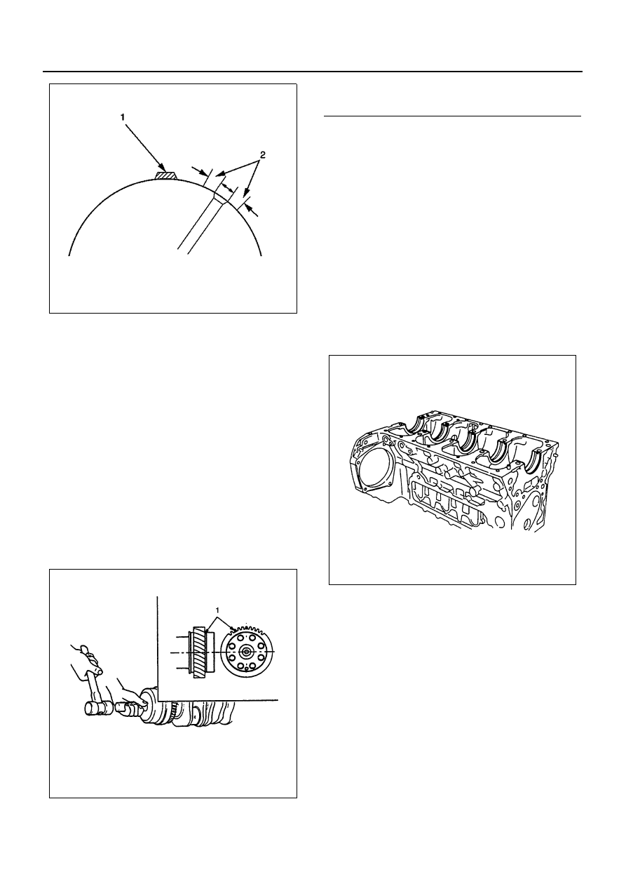
1) Use a piston heater to heat the crankshaft gear

to 170 — 250

°C (338 — 482°F).

2) With the alignment mark “S” on the side of the

crankshaft gear turned outward, align the
groove on the gear side with the crankshaft pin
position and hammer it in with a crankshaft
gear installer until it hits the bottom.

Caution:
When hammered in with the gear slanted, the crank-
shaft gear may be caught in the middle and cannot be
hammered in fully. Hammer it inquickly enough not to al-
low a shaft line along the gear and the crankshaft to
slant.

Crankshaft Gear Installer: 8-9439-6819-0

3. Crankshaft Bearing Upper

When replacing the crankshaft or the crankshaft
bearing with a new one, select the crankshaft bear-
ing according to the respective grades stamped on
the crankshaft and the cylinder body.
Above works refer to “CRANKSHAFT” section in
this manual.
All upper bearings have oil grooves.
1) Carefully wipe any foreign material from the up-

per bearing.

Caution:
Do not apply engine oil to the bearing back faces and
the cylinder body bearing fitting surfaces.

2) Locate the position mark applied at disassem-

bly if the removed upper bearings are to be re-
used.

4. Thrust Bearing Upper

1) Install the thrust bearing upper to the front side

of the cylinder body No.5 journal. At this time,
the thrust bearing upper may be pasted to the
cylinder body with grease. However, wipe off
any excessive grease clean.

2) The thrust bearing oil grooves must be facing

the sliding faces.

N6A0223E

N6A0224E

Legend

1. Alignment mark

N6A0207E

ENGINE MECHANICAL 6A-47

5. Crankshaft Assembly

1) Apply an ample coat of the engine oil to the

crankshaft journals and the crankshaft bearing
surfaces before installing the crankshaft with
timing gear.

2) With the installed crankshaft pressed on to the

rear side, install the thrust bearing upper to the
rear side of the cylinder body No.5 journal.

3) The thrust bearing oil grooves must be facing

the sliding faces.

6. Crankshaft Bearing Lower

All lower bearings does not have oil grooves.
1) Carefully wipe any foreign material from the

lower bearing.

Caution:
Do not apply engine oil to the bearing back faces and
the crankcase bearing fitting surfaces.

2) Locate the position mark applied at disassem-

bly if the removed lower bearings are to be re-
used.

7. Thrust Bearing Lower

1) Install the thrust bearing lower to the rear side

of the crankcase No.5 journal.

2) The thrust bearing oil grooves must be facing

the sliding faces.

8. Crankcase

1) Apply a 3 mm (0.12 in) bead of recommended

liquid gasket (Three Bond 1207C) or its equiv-
alent to the crankcase upper surface as shown
in the illustration.

2) Carefully place the crankcase on the cylinder

body.

• Install the crankcase within 20 minutes after

application of liquid gasket.

N6A0226E

N6A0227E

N6A0228E

6A-48 ENGINE MECHANICAL

3) Tighten the crankcase to the specified torque in

the numerical order shown in the illustration.

Tighten:
Crankcase bolt (M14: (1) — (10)) to

• 1st step: 98 N

⋅m (10 kg⋅m / 72 lb⋅ft)

• 2nd step: 132 N

⋅m (13.5 kg⋅m / 98 lb⋅ft)

• 3rd step: 30 — 60

°

Tighten:
Crankcase bolt (M10: (1) — (17)) to 37 N

⋅m (3.8 kg⋅m /

27 lb

⋅ft)

Angle gauge: 5-8840-0266-0

9. Piston and Connecting Rod Assembly

10. Connecting Rod Lower Bearing

Legend

1. Liquid gasket

N6A1622E

N6A1415E

N6A0208E

ENGINE MECHANICAL 6A-49

11. Connecting Rod Cap Assembly

Above works refer to “PISTON AND CONNECT-
ING ROD” section in this manual.

12. Oil Pump Assembly
13. Idle Gear A
14. Flywheel Housing
15. Power Steering Pump Idle Gear
16. Power Steering Pump Idle Gear Cover

Above works refer to O”IL PUMP” section in this
manual.

17. Oil Thermo Valve (4HF1, 4HF1-2, 4HG1, 4HG1-T)

Insert the oil thermo valve into the cylinder body.

18. Bypass Valve (4HE1-TC)

Insert the bypass valve into the cylinder body.

19. Front Retainer

1) Carefully wipe any foreign material from the cyl-

inder body front face.

2) Apply 2.5 — 3.5 mm (0.10 — 0.14 in) bead of

the recommended liquid gasket (Three Bond
1207C) or its equivalent on the groove of the

front retainer fitting surface shown in the illus-
tration.

3) Install the O-rings (2 pieces) to the front retain-

er.

• Install the front retainer within 7 minutes after

application of liquid gasket.

• For the dislocation of liquid gasket, refer to the

illustration.

4) Align the cylinder body knock pins with the front

retainer knock pin holes.

Tighten:
Front retainer bolt to 24 N

⋅m (2.4 kg⋅m / 17 lb⋅ft)

20. Water Pump Assembly
21. Water Pump Pulley
22. Oil Pump Strainer

N6A0195E

N6A0232E

Legend

1. O-ring
2. Liquid gasket

N6A1623E

N6A0234E


Content   ..  324  325  326  327   ..