Isuzu N-Series. Service manual - part 1190


  Index      Isuzu     Isuzu N-Series - service and repair manual


Search            


Content   ..  1188  1189  1190  1191   ..


Isuzu N-Series. Service manual - part 1190


SRS CONTROL SYSTEM 9C-7
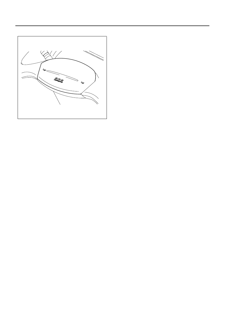
SRS airbag assembly

SRS airbag consists of the airbag and the inflator (a can
with gas generator agent and a ignition device). SRS
control unit sends current to the deployment circuit in the
event of front collision over certain degree of impact.
Passage of electric current in the inflator will light the
gas generator agent in the SRS airbag.
Gas generated in the reaction rapidly inflate the airbag.
A shorting clip is equipped to the SRS airbag. Upon re-
moval of SRS airbag connector, the shorting clip shorts
the SRS airbag circuit.
The circuit to SRS airbag is shorted in this manner. This
prevents unnecessary deployment of SRS airbag when
servicing SRS airbag assembly, steering column or oth-
er SRS system parts.

N9A0065E

9C-8 SRS CONTROL SYSTEM

Part Location Diagram

A-1 AIR BAG

BATTERY

FL-2 FUSIBLE LINK

B-1 EARTH; FRAME LH (FRONT)

FUSE BOX ASM
F-16, F-18

B-79 DATA LINK CONNECTOR 

B-51 SRS WARNING LIGHT

(METER)

B-244 SRS COIL

B-67

B-276 SRS COUPLING 

CONNECTOR

B-243 SRS CONTROL UNIT

H-7

B-275 EARTH; FRAME RH (FRONT)

N9A0066E

SRS CONTROL SYSTEM 9C-9

Circuit Diagram

0.85

B

1.25 B

0.5
SB

0.5

B

0.5

B

0.5

B/R

0.5

B/Y

0.5

W/R

0.5

W/R

0.85

B

0.5

B/R

0.5

B/R

0.5

B/R

0.5
GY

0.5

B

0.5

B

0.5
SB

0.5
GY

FRAME

P-5

P-1

P-2

P-3

P-4

FL-2

KEY SW

STARTER SWITCH

METER

AIR BAG

SRS COUPLING 
CONNECTOR

SHORTING 
CONNECTOR

SHORTING 
CONNECTOR

SRS COIL

AIR BAG

SRS CONTROL UNIT

SRS COUPLING 
CONNECTOR

DATA LINK CONNECTOR

B-1

B-1

B-275

FRAME LH (FRONT)

FRAME LH (FRONT)

FRAME RH (FRONT)

3.0
W/L

3.0 W/L

3.0 B/Y

8.0B

2L

40A

H-7

1

B-67

B-67

2

3

OFF

ACC

ON

ST

F-16 10A

METER

F-18 10A

SRS

B-51

18

B-276

4

B-276

1

B-276

B-243

B-243

2

15

B-243

B-276

B-276

B-276

19

B-79

5

B-79

4

4

B-243

16

6

7

B-79

B-79

7

13

8

B-243

6

B-243

5

14

B-51

1

B-244

2

B-244

B-243

18

B-243

20

B-243

8

B-243

A-1

A-1

7

0.5

Y

0.5

Y/B

N9A0085E

9C-10 SRS CONTROL SYSTEM

Connector List

No.

Connector Face

A-1

A-1

B-1

B-51

B-67

B-67

B-79

B-243

002-045

002-046

000-001

020-004

004-002

2
4

1
3

004-001

1

2

3

4

016-005

8

7

6

5

4

3

2

1

16

15

14

13

12

11

10

9

021-001

B-244

B-244

B-275

B-276

B-276

P-1

P-2

P-3

No.

Connector Face

002-043

002-044

000-020

008-009

1 2

3

8

4 5 6 7

008-010

1

2

3

8

4

5

6

7

000-004

000-006

000-006


Content   ..  1188  1189  1190  1191   ..