Content .. 1189 1190 1191 1192 ..
Isuzu N-Series. Service manual - part 1191
SRS CONTROL SYSTEM 9C-11
H-7
Procedure of Trouble Diagnosis
Diagnostic Trouble Code (Self-diagnosis Code)
At first, perform “SRS system check”. “SRS system
check” is to check whether “SRS” warning lamp oper-
ates properly and confirms SRS diagnostic trouble code
(DTC) using warning lamp blinking or Tech 2.
1. Active diagnostic trouble code: Function fault cur-
rently detected. Active diagnostic trouble codes
are stored in the RAM (Random Access Memory).
(Code of current trouble)
2. History diagnostic trouble code: Function fault de-
tected after history memory had been cleared last
time. History diagnostic trouble codes are stored in
the EEPROM. (Trouble code occurred in the past)
System Diagnostic Method
System diagnostic method is a standardized method to
repair all the electric/electronic (E/E) systems. Diagnos-
tic procedure is always used to solve the problem of E/
E system and is a starting point when service is re-
quired. Procedure of diagnosis is described in the fol-
lowing steps:
1. Confirm a customer’s complaint.
• It is necessary for technicians to understand the
normal operations of the systems to confirm a
customer’s complaint.
2. Perform pre-inspection.
• Perform overall visual check.
• Review service record.
• Detect noise or abnormal odor.
• Collect the diagnostic trouble code information
for effective repair.
3. Check service information.
• This includes video, news letter, etc.
If DTC is Stored
Perform service correctly according to the specified
DTC chart.
If there is No DTC
Select symptom from the diagnostic chart according to
symptom. Complete the service following diagnostic
procedure. You may also perform inspection by refer-
ring function diagnosis.
If there is No Applicable Symptom
1. Confirm the complaint in detail.
2. Create diagnostic plan.
3. Use wiring diagram and principle of operation.
Ask for technical support when repair history is available
for similar case. Connect technician’s knowledge with
the effective usage of available service information.
If there is Intermittent (Intermittent Trouble)
The trouble situation not occurring constantly is called
intermittent (intermittent trouble). Perform the following
steps to solve the intermittent trouble.
1. Check the DTC information and SRS data.
2. Evaluate symptom and situation explained by the
customer.
3. Check the circuits or the electric system compo-
nents using check sheet or other methods.
If the Trouble is not Detected
In this case, the vehicle is judged as it operates properly.
The condition explained by the customer may be the
normal condition. Confirm the customer’s complaint
comparing with the condition of the vehicle to that of an-
other vehicle. That condition may mean an intermittent
trouble. Confirm the complaint in the situation the cus-
tomer explains before returning the vehicle to the cus-
tomer.
1. Confirm the complaint again.
If the complaint can not be fully detected or identi-
fied, the vehicle must be diagnosed again. Confirm
the complaint one more time. The complaint may
be an intermittent trouble as defined in “If there is
intermittent”, but it may also be possible that the
vehicle is normal.
P-4
P-5
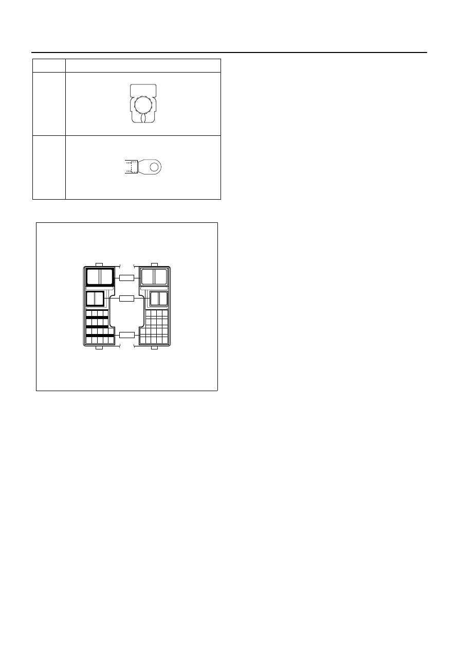
No.
Connector Face
000-004
000-002
1
2
1
2
1 2 3 4
5 6 7 8
9 10 11 12 13
14 15 16 17 18
2
1
2
1
4 3 2 1
8 7 6 5
13 12 11 10 9
18 17 16 15 14
H - 6
H - 7
H - 8
N8A5489E