Isuzu N-Series. Service manual - part 1188


  Index      Isuzu     Isuzu N-Series - service and repair manual


Search            


Content   ..  1186  1187  1188  1189   ..


Isuzu N-Series. Service manual - part 1188


SRS 9B-35

Legend

1. Snap ring
2. Screw

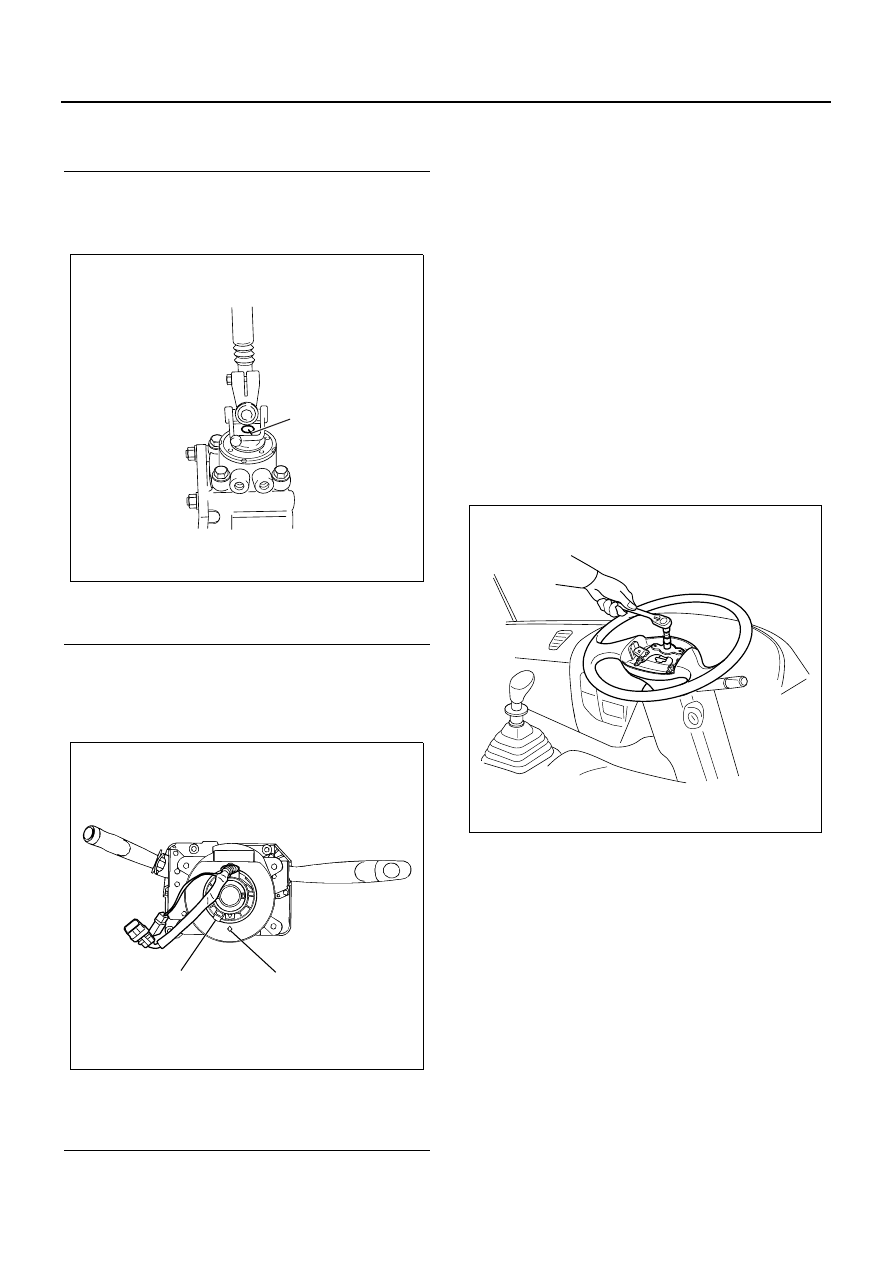
5. Set the steering wheel in the straight position.
6. Install the combination switch assembly (including

SRS coil).

Legend

1. Alignment mark

7. Rotate the SRS coil clockwise fully and back off it

about 4 rotations to align neutral mark.
(Rotating is not necessary when assembling new
SRS coil with lock pin.)

Legend

1. Lock pin
2. Neutral mark

Caution:

• While rotating the SRS coil clockwise fully, stop ro-

tating if resistance is felt. Additional rotation by
force may lead to damage or disconnection on
SRS coil cable.

• More than 3 rotations from neutral point in each di-

rection lead to damage on SRS coil.

8. Connect SRS harness connector (yellow) and

combination switch harness connector located in
the lower portion of steering column.

9. Make sure that tires are in the straight position.

10. While checking the engagement in canceller of

flasher, install steering wheel straight and align the
setting marks.

11. Tighten the mounting nut which installs steering

wheel to the specified torque.

Tighten:
Nut to 42 

± 6.8 N⋅m (4.3 ± 0.7 kg⋅m / 31.0 ± 5.0 lb⋅ft)

12. For new combination switch (including SRS coil)

with lock pin, pull the lock pin in front to bend.

13. Put the harness through the harness through hole

and assembly the cover.

14. Connect the 2-pole connector (yellow) and horn

harness located in the back of airbag assembly.

15. Secure the connector and harness.
16. Install the airbag to steering wheel and tighten the

bolt to the specified torque.

Tighten:
Bolt to 8.0 

± 2.0 N⋅m (0.8 ± 0.2 kg⋅m / 5.9 ± 1.5 lb⋅ft)

1

N9A0061E

1

2

N9A0053E

N9A0050E

9B-36 SRS

WARNING:

DO NOT USE SRS AIRBAG OF OTHER VEHICLE OR
MODEL. BE SURE TO CONFIRM THE PART NUM-
BER TO USE APPROPRIATE SRS AIRBAG.

17. Install the steering cowl.

WARNING:

WHEN INSTALLING STEERING COWL, ASSEMBLE
CAREFULLY NOT TO LET WIRE HANG UP ON
STARTER SWITCH, COMBINATION SWITCH OR
SRS COIL.

18. Resume the function of SRS. (Refer to “Procedure

to resume the function of SRS”.)

Special tool

5-8840-2035-0 Steering wheel puller

N9A0044E

N9A0052E

SRS CONTROL SYSTEM 9C-1

SEAT BELT, SRS AIRBAG

SECTION 9C

SRS CONTROL SYSTEM

Contents

SRS Control System .............................................9C-2

Precautions on Service Work ............................9C-2
Description of Function and Operation ..............9C-4
Part Location Diagram.......................................9C-8
Circuit Diagram..................................................9C-9
Connector List .................................................9C-10
Procedure of Trouble Diagnosis ......................9C-11
List of Function Checks ...................................9C-15
SRS System Check .........................................9C-15
Chart A SRS Control Unit Function Check ......9C-18
Chart B “SRS” Warning Lamp Turns on Continuously .....9C-20
Chart C “SRS” warning lamp does not come on .....9C-22
Trouble Diagnosis with Scan Tool ...................9C-24
List of Diagnostic Trouble Code ......................9C-27
DTC: 14 Connector is Half-connected.............9C-28
DTC: 21 Resistance of SRS Airbag Deployment Cir-
cuit is Large .....................................................9C-30
DTC: 22 Resistance of SRS Airbag Deployment Cir-
cuit is Small .....................................................9C-33
DTC: 24 SRS Airbag Deployment Circuit is Shorted to 
Ground.............................................................9C-36
DTC: 25 SRS Airbag Deployment Circuit is Shorted to 
Ignition Voltage................................................9C-39
DTC: 26 SRS Airbag Deployment Circuit is Open ......9C-42
DTC: 51 SRS Airbag Deployment Current Had Output ....9C-45
DTC: 53 Specific Trouble when SRS Airbag Deploy-
ment Current Had Output ................................9C-47
DTC: 54 Deployment Output by Onboard Deployment 
System Communication...................................9C-49
DTC: 55 Vehicle Type Error ............................9C-51
DTC: 61 Warning lamp circuit trouble..............9C-53
DTC: 63 Power Supply Voltage Failure...........9C-55
DTC: 71 SRS Control Unit Internal Trouble.....9C-57
Special Tool.....................................................9C-58

9C-2 SRS CONTROL SYSTEM

SRS Control System

Precautions on Service Work

WARNING:

WHEN SERVICING SRS SYSTEM PARTS (SRS CON-
TROL UNIT, AIRBAG, HARNESS, ETC.) OR ITS CIR-
CUMFERENCE, STOP TEMPORARILY THE
FUNCTION OF SRS ACCORDING TO THE PROCE-
DURE. FAILURE TO FOLLOW THE PROCEDURE
MAY CAUSE INJURY DUE TO SRS AIRBAG DE-
PLOYMENT OR UNNECESSARY REPAIR.

Turn the starter switch to “LOCK” at first. Then, discon-
nect the battery or remove the fuse which sends power
to SRS control unit. After that, do not perform the work
at least 15 seconds since airbag may be deployed. In
the service procedure, remove “SRS fuse” and detach
SRS airbag from deployment circuit to prevent SRS
airbag from unnecessary deploying. If removing SRS
airbag from deployment circuit according to “Procedure
to stop the function of SRS” in this topic, service work
can be performed immediately without waiting for 15
seconds.

About tools

WARNING:

WHEN SERVICING SRS, DO NOT USE ELECTRICAL
TEST EQUIPMENT EXCEPT ONES DESCRIBED IN
THIS MANUAL TO AVOID DEPLOYMENT OF SRS
AIRBAG. FAILURE TO FOLLOW THIS MANUAL MAY
CAUSE INJURY DUE TO UNNECESSARY DEPLOY-
MENT OF SRS AIRBAG.

Familiarize yourself with use of Tech 2, SRS substitute
load (5-8840-2421-0), Connector test adapter kit (5-
8840-0385-0), DMM (digital multi-meter, 5-8840-0366-
0), to be able to measure voltage and resistance.

Necessary repair and inspection after collision

• If the parts of this system are damaged, replace-

ment is needed. If mounting portion of SRS parts
are damaged, replacement is needed.

• Never use system parts of other vehicle.
• Do not disassemble or repair SRS control unit,

SRS coil assembly or SRS airbag. These parts
must be replaced with new ones.

• Confirm the part number to make sure that replace-

ment SRS parts are legitimate.

WARNING:

DO NOT USE SRS AIRBAG OF OTHER VEHICLE OR
MODEL. BE SURE TO CONFIRM THE PART NUM-
BER TO USE APPROPRIATE SRS AIRBAG.

Caution:

Always replace the SRS coil with combination switch as-
sembly, since the SRS coil assembly is supplied as an
item in the combination switch.

Caution:

After repair and replacement, set back the SRS airbag
to the correct specification so that it is operated properly.
It is necessary to replace SRS control unit and SRS
airbag, and inspect the dimension of steering column. If
the mounting bracket of SRS control unit are damaged
clearly, replacement is needed. Besides, the dimension
of steering column should be inspected regardless of
SRS airbag deployment.

Replacement and Inspection of Parts After Collision
with Deployment
If front collision with airbag deployment occurs, following
system parts must be replaced. It is necessary to check
whether SRS coil assembly is damaged.

• SRS airbag assembly
• SRS control unit
• Combination switch assembly (including SRS coil)

Caution:

Refer to “Replacement guideline for SRS control unit”
described later for important information about replace-
ment of SRS control unit after collisions with deployment
and without.

• Inspect SRS coil assembly harness and connector

for burn due to excessive heat, dissolution or dam-
age. If damaged, replace it. Refer to “SRS System
Assembly” in SRS section.

Inspection of Parts After Collision with or Without
Deployment
The certain parts of this system and supplemental re-
straint system should be inspected regardless of SRS
airbag deployment. The parts to be inspected are shown
as follows.

• Steering column: inspect the dimension according

to “Examination of damage for steering column”
described in “SRS System Assembly” in SRS sec-
tion.

• Steering support bracket: inspect for distortion,

bent, crack or other damage.

• Instrument panel bracket: inspect for distortion,

bent, crack or other damage.

• Seat belt and its mounting portion: refer to “Seat

Belt” section.

Replacement Guideline for SRS Control unit
If collision with SRS airbag deployment occurs, replace-
ment of SRS control unit is needed. If “SRS” warning
lamp illuminates, perform SRS diagnosis according to
“Function check: SRS system check”.

Damaged Harness
If the SRS harness is damaged, it must be replaced.


Content   ..  1186  1187  1188  1189   ..