Seat Alhambra. Instruction - part 2


  Index      Seat     Seat Alhambra. Instruction


Search            copyright infringement  


Content      ..      1      2      3      ..


Seat Alhambra. Instruction - part 2


-------------------------------------------------------------------------------------------------------------------------------------------------------------

The essentials

Child seats

Important information regarding the
front passenger's airbag
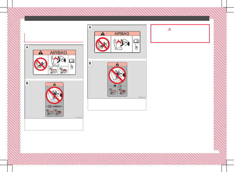
Fig. 34 

Airbag stickers - version 1: on the

front passenger's sun visor  and on the rear
frame of the front passenger's door .

Fig. 35 

Airbag stickers - version 2: on the

front passenger's sun visor  and on the rear
frame of the front passenger's door .

A sticker with important information about
the passenger airbag is located on the pas-
senger's sun visor and/or on the passenger
side door frame.

››› 

 in Introduction on page 74

››› 

page 75

21

-------------------------------------------------------------------------------------------------------------------------------------------------------------

-------------------------------------------------------------------------------------------------------------------------------------------------------------

The essentials

Different mounting systems

Fig. 36 

On the rear seats: Possible installations

for the child seat.

Always secure child seats properly and safely
in the vehicle according to the child seat
manufacturer's installation instructions.

Mounted child seats must rest correctly on
the vehicle's seat and must not move or rock
more than 2.5 cm (1 inch).

Child seats equipped for a Top Tether strap
must also be secured using the Top Tether re-
taining strap in the vehicle 

››› 

page 23

. Only

secure the retaining belt to the rings fitted for
this purpose and identified as Top Tether.
Not all rings can be used with the Top Tether
system. Always tighten the Top Tether retain-
ing strap so that the child seat fits snugly
against the corresponding seat in the vehi-
cle.

Specific mounting systems for each country

Europe: ISOFIX retaining rings and upper
retaining strap 

››› 

page 23

 and

››› 

page 23

.

Three-point seat belt and upper retaining
strap 

››› 

page 22

.

The systems include the child restraint sys-
tem mounting with an upper retaining strap
(Top Tether) and lower anchoring points on
the seat.

Securing child seats with the seat belt

Securing the child seat using the seat belt

Please read and observe the child seat

manufacturer's handling instructions.

A

B

Positioning the child seat on the seat ac-

cording to the manufacturer's instructions.

The seat belt height adjustment must be as

high as possible.

Fasten the seat belt or pass it around the

child seat structure in the manner described
in the manufacturer's instructions.

Make sure the seat belt is not twisted.

Insert the latch plate into the buckle for the

appropriate seat and push it down until it is
securely locked with an audible click.

Ensure that the upper belt web lies tightly

on the child seat.

Pull the belt (it must be no longer possible

to pull the lower belt webbing out).

22

-------------------------------------------------------------------------------------------------------------------------------------------------------------

-------------------------------------------------------------------------------------------------------------------------------------------------------------

The essentials

Removing the child seat
The seat belt must not be unfastened until
the vehicle has come to a standstill.

Press the red button on the buckle. The

latch plate is released from the buckle.

Guide the belt back by hand so that it rolls

up easily and the trim will not be damaged.

Remove the child seat from the vehicle.

››› 

 in Safety instructions on page 75

Fix the child seat with the lower an-
chor points (ISOFIX)ISOFIX system

Fig. 37 

Version 2: identification of the anchor

points for the child seat on the vehicle seat

There are 

two retaining rings, the so-called

lower anchor points, on each rear seat or,
where applicable, on the front passenger

seat. The retaining rings are attached to the
seat frames.

Child seats with rigid mounting

Observe the manufacturer's instructions

when installing and removing the child seat.

Press the child seat onto the retaining rings

››› 

Fig. 37

 in the direction of the arrow. The

child seat must be safely engaged and click
audibly into place.

Pull on both sides of the child seat to en-

sure that it is secure.

Child seat with adjustable retaining straps

Observe the manufacturer's instructions

when installing and removing the child seat.

Place the child seat on the seat cushion

and attach the retaining strap hooks to the
retaining rings 

››› 

Fig. 37

.

Tighten the straps evenly using the corre-

sponding adjustment device. The child seat
must sit flush against the vehicle seat.

Pull on both sides of the child seat to en-

sure that it is secure.

››› 

 in Safety instructions on page 75

Securing a child seat using a Top Teth-
er retaining strap

Fig. 38 

Upper retaining strap hooked in the

luggage compartment

Observe the manufacturer's instructions

when installing and removing the child seat

››› 

 in Safety instructions on page 75

.

Raise the head restraint behind the child

seat until it engages.

Secure the child seat to the lower anchor

points 

››› 

page 23

.

Pull the upper child seat retaining strap

back to the seat backrest of the rear seat, 

be-

low or on both sides of the head restraint
(depending on the child seat model).

Hook the upper retaining strap to the corre-

sponding retaining ring (for Top Tether) on
the back of the seat backrest on the rear seat

››› 

Fig. 38

.

»

23

-------------------------------------------------------------------------------------------------------------------------------------------------------------

-------------------------------------------------------------------------------------------------------------------------------------------------------------

The essentials

Push the head restraint down as far as it

will go. Ensure that it does not interfere with
the seatbelt from the upper attachment.

Tighten the strap so that the top of the

child seat rests on the seat backrest.

››› 

 in Safety instructions on page 75

Starting the vehicle

Ignition lock

Fig. 39 

Vehicle key positions

Switch ignition on: Place the key in the igni-
tion and start the engine.

Locking and unlocking the steering wheel

Engaging the steering wheel lock: Remove

the key from the ignition and turn the wheel

until it locks. In vehicles with an automatic
gearbox, the gear lever must be in the 

P posi-

tion in order to remove the key. If necessary,
press the locking key on the selector lever
and release it again.

Unlocking the steering wheel: Put the key

into the ignition and turn it at the same time
as the steering wheel in the direction indica-
ted by the arrow. If it is not possible to turn
the steering wheel, it may be because it is
locked.

Turning on/switching off the ignition, glow
plugs reheating

Switch ignition on: Turn the key to the 

2

position.

Switch ignition off. Turn the key to the 

1

position.

Diesel vehicles : The glow plugs reheat

when the ignition is switched on

Starting the engine

Instruction gearbox: press the clutch pedal all

the way down and move the gearbox lever in-
to neutral.

Automatic gearbox: Press the brake pedal

and move the selector lever to the 

P position

or into 

N.

Turn the key to the 

3

 position. The key au-

tomatically returns to the 

2

 position. Do not

press the accelerator.

Start-Stop System*
When you stop and release the clutch pedal,
the Start-Stop system* turns off the engine.
The ignition remains switched on.

››› 

 in Ignition lock on page 183

››› 

page 183

Lights and visibility

Light switch

Fig. 40 

Dash panel: light control.

Turn the switch to the required position

››› 

Fig. 40

.

24

-------------------------------------------------------------------------------------------------------------------------------------------------------------

-------------------------------------------------------------------------------------------------------------------------------------------------------------

The essentials


When the igni-
tion is switched
off

When the ignition
is on

Fog lights, dipped
beam and side
lights off.

Lights off or daytime
driving light on.



The guidance lights
may be switched
on.

Automatic dipped
beam control or day-
time driving light on.

Side light on.

Dipped beam off; if
necessary, the side
light comes on for a
time.

Dipped beam switch-
ed on.

 Front fog lights: move the switch to the

first position, from positions ,  or .

 Rear fog light: move the switch completely

from positions ,  or .

Switching off fog lights: Push the switch or
turn it to the  position.

››› 

 in Switching lights on and off on

page 129

››› 

page 128

Turn signal and main beam lever

Fig. 41 

Turn signal and main beam lever

More the lever to the required position:

Right turn signal: Right-hand parking
light (ignition switched off).
Left turn signal: Left-hand parking light
(ignition switched off).
Main beam switched on: Control lamp 
lit up on the instrument panel.
Headlight flasher: lit up when the lever is
pushed. Control lamp  lit up.

Lever all the way down to switch it off.

››› 

 in Switching lights on and off on

page 129

››› 

page 129

1

2

3

4

Hazard warning lights

Fig. 42 

Dash panel: switch for hazard warn-

ing lights.

Switched on, for example:

When approaching a traffic jam

In an emergency

The vehicle has broken down

When towing or being towed

››› 

 in Hazard warning lights on

page 132

››› 

page 132

25

-------------------------------------------------------------------------------------------------------------------------------------------------------------

-------------------------------------------------------------------------------------------------------------------------------------------------------------

The essentials

Interior lights

Button/Position: Function

Switches interior lights off.

Switches interior lights on.

Switches door contact control on (central
position).
The interior lights come on automatically
when the vehicle is unlocked, a door is
opened or the key is removed from the igni-
tion.
The lights go off a few seconds after all the
doors are closed, the vehicle is locked or
the ignition is switched on.

Turning the reading light on and off

Ambient light: in the door panel, it changes
colour (white or red) depending on the driv-
ing mode.

››› 

page 134

Windscreen wipers and window wiper
blade

Fig. 43 

Operating the windscreen wiper and

rear wiper

Move the lever to the required position

0



Windscreen wiper off.

1

Windscreen wipers interval wipe.
Using the control 

››› 

Fig. 43


A

 adjust

the interval (vehicles without rain sen-
sor), or the sensitivity of the rain sensor.

2



Slow wipe.

3



Continuous wipe.

4



Brief wipe - short wipe. Hold the lever
down for more time to increase the wipe
frequency.

5

Automatic wipe for cleaning wind-
screens with the lever up.

Move the lever to the required position

6

Interval wipe for rear window. The wiper
wipes the window at 6-second intervals.

7

Automatic wipe for cleaning rear win-
dows with the lever pressed.

››› 

 in Window wiper lever on page 135

››› 

page 135

››› 

page 54

SEAT information system

Introduction

With the ignition switched on, it is possible
to read the different functions of the display
by scrolling through the menus.

In vehicles with a multifunction steering
wheel, there are no buttons on the wind-
screen wiper lever. The multifunction display
can only be controlled from the buttons on
the steering wheel.

The number of menus displayed on the in-
strument panel will vary according to the ve-
hicle electronics and equipment.

26

-------------------------------------------------------------------------------------------------------------------------------------------------------------

-------------------------------------------------------------------------------------------------------------------------------------------------------------

The essentials

A specialised workshop will be able to pro-
gramme or modify additional functions, ac-
cording to the vehicle equipment. SEAT rec-
ommends taking your car in for technical
service.

Some menu options can only be read when
the vehicle is at a standstill.

As long as a priority 1 warning is displayed, it
will not be possible to read the menus. To
display the menus, confirm the warning by
pressing 

OK

.

Summary of the menu structure

Multifunction display (MFD) 

››› 

page 29

Travelling time

Current fuel consumption

Average fuel consumption

Operating range

Distance covered

Average speed

Digital display of speed

Oil temperature digital display

Speed warning

Audio 

››› 

Booklet Radio

 or 

››› 

Booklet Navi-

gation system

Navigation 

››› 

Booklet Navigation system

Telephone 

››› 

Booklet Radio

 or 

››› 

Book-

let Navigation system

Auxiliary heating 

››› 

page 177

Activation

Programme On / Off

Disconnection

Timer 1-3

Day

Time

Minute

Activate

Duration

Operating mode

Heat

Ventilation

Day

Default setting

Vehicle condition 

››› 

page 28

Configuration 

››› 

page 30

Multifunction display data

Travelling time

Current fuel consumption

Average fuel consumption

Distance covered

Operating range

Average speed

Digital display of speed

Speed warning

Compass

Convenience 

››› 

page 31

Central locking system (Central locking)

Automatic lock (Auto. lock) On / Off

Automatic unlocking (Auto. unlock.)
On / Off

Unlocking doors (Door unlock.: All,
One door, Vehicle side, Individual)

Back

Electric windows

Off

All

Driver

Back

Mirror angle (Mirror angle) On / Off

Adjusting mirrors (Adjust. mirrors)

Individual

Synchronised

Back

Factory settings (Factory settings)

Back

Lights & visibility 

››› 

page 31

Coming Home

Leaving Home

Footwell light

Convenience turn signals On / Off

Default setting

Tourist light On / Off

Time

Winter tyres

Language

Units

Second speed display On / Off

»

27

-------------------------------------------------------------------------------------------------------------------------------------------------------------

-------------------------------------------------------------------------------------------------------------------------------------------------------------

The essentials

Autohold

Service

Info

Reset

Default setting

Using the menus on the instrument
panel

Fig. 44 

Windscreen wiper lever: buttons to

access the instrument panel menus

Fig. 45 

Multifunction steering wheel: buttons

to access the instrument panel menus

Enabling the main menu

Switch the ignition on.

If a message or vehicle symbol is dis-

played, press 

OK

 (

››› 

Fig. 44


A

 or 

››› 

Fig. 45

).

If managed from the windscreen wiper lev-

er: the main menu list is displayed.

If managed from the multifunction steering

wheel: the main menu list is not displayed.
To scroll through the options of the main
menu, press the arrow keys 


 or 


 re-

peatedly 

››› 

page 28

.

Select a submenu

Press rocker switch 

››› 

Fig. 44


B

 upwards

or downwards, or, on the multifunction steer-
ing wheel, turn the thumbwheel until you
reach the required menu option.

The selected option is displayed between

two horizontal lines. In addition, a triangle is
displayed on the right .

To select the submenu, press 

OK

.

Making changes according to the menu

Use the rocker switch on the windscreen

wiper lever or the thumbwheel on the multi-
function steering wheel to make the required
modifications. To scroll through numbers
more quickly, hold the rocker switch down or
turn the thumbwheel more quickly (fast for-
ward or reverse).

Mark or confirm the selected option with

OK

.

Main menu

MFD

Information and possible configura-
tions of the multifunction display
(MFD).

››› 

page 29

Audio

If the radio is on, the station is dis-
played.
In CD mode, the current CD is played.

››› 

Booklet Radio

 or 

››› 

Booklet naviga-

tion system

28

-------------------------------------------------------------------------------------------------------------------------------------------------------------

-------------------------------------------------------------------------------------------------------------------------------------------------------------

The essentials

Navigation

When the navigation to destination is
on, change of direction arrows and a
proximity bar are displayed. These
symbols are similar to those used in
the navigation system.
If navigation to destination is not on,
the direction of travel (compass) and
the name of the street on which you
are driving are displayed.

››› 

Booklet Navigation system

Telephone

Information and possible configura-
tions of the mobile phone preinstalla-
tion.

››› 

Booklet Radio

 or 

››› 

Booklet Naviga-

tion system

Parking heat-
ing

Information and configurations of the
parking heating:
switching the parking heating on or
off. Select the operating mode and du-
ration.

››› 

page 177

Vehicle status

Current warning or information texts.
This option only appears when one of
the following texts is available. The
number of available messages is dis-
played. Example 1/1 or 2/2.

››› 

page 100

Configuration

Different setting options, for example,
the Convenience, Lighting & Visibility
menus, and the time, speed warning
with winter tyres, language, units of
measurement, or “Display off”.

››› 

page 30

MFD

 (multifunction display) menu

The multifunction display (MFD) has two au-
tomatic memories: 

1 - Partial memory and 2 -

Total memory. The selected memory will be
shown in the upper right-hand corner of the
display.

With the ignition switched on, and memory 1
or 2 displayed, briefly press 

OK

 to change

from one memory to another

1

Trip memo-
ry (for a sin-
gle jour-
ney).

The memory stores the values for the
journey and the consumption from the
moment the ignition is switched on until
it is switched off again.
If the journey is broken for more than 2
hours, the memory is automatically
erased. If the journey is continued in less
than 2 hours after the ignition is switch-
ed off, the new data is added to the data
already stored in the memory.

2

Total mem-
ory (for all
journeys).

The memory records the values for a spe-
cific number of partial trips, up to a total
of 19 hours and 59 minutes or 99 hours
and 59 minutes, or 1999.9 km (or miles)
for 9999 km (or miles), depending on the
model of instrument panel. On reaching
either of these limits, the memory is au-
tomatically erased and starts to count
from 0 again.

Possible displays

Travelling time

This indicates the hours (h) and mi-
nutes (min) since the ignition was
switched on.

Current fuel
consumption

The current fuel consumption while
driving is displayed in l/100 km (or
miles per gallon, mpg); when the en-
gine is running but the vehicle is not
moving, in l/h (or gallons per hour).

Average fuel
consumption

When the ignition is switched on, the
average consumption (in l/100 km or
in mpg) is displayed after the vehicle
has moved approximately 100 metres
(328 feet). Otherwise horizontal lines
are displayed. The value shown is up-
dated approximately every 5 seconds.

Operating
range

Approximate distance in km (or miles)
that can still be travelled with the fuel
remaining in the tank, assuming the
same style of driving is maintained.
This is calculated using the current
fuel consumption.

Distance cov-
ered

Distance travelled, after ignition is
switched on, in km (or miles).

Average speed

After the ignition is switched on, the
average speed will be shown after a
distance of approximately 100 metres
(328 feet) has been travelled. Other-
wise horizontal lines are displayed.
The value shown is updated approxi-
mately every 5 seconds.

Digital display
of speed

Current speed displayed digitally.

Oil tempera-
ture digital
display

Updated engine oil temperature digi-
tal display

»

29

-------------------------------------------------------------------------------------------------------------------------------------------------------------

-------------------------------------------------------------------------------------------------------------------------------------------------------------

The essentials

Speed warn-
ing at --- km/h

If the stored speed is exceeded (be-
tween 30 - 250 km/h, or 18 -
155 mph), an audible warning is given
together with a visual warning.

Changing between display modes

In vehicles without multifunction steering

wheel: press the lever.

Vehicles with a multifunction steering

wheel: press 

 or 

.

Storing a speed for the speed warning

Select the display 

Speed warning at

--- km/h

.

Press 

OK

 to store the current speed and

switch off the warning.

In addition, set the required speed by

pressing the rocker switch on the windscreen
wiper lever 

 or 

 buttons on the multifunc-

tion steering wheel for 5 seconds. Next,
press 

OK

 again or wait a few seconds. The

speed is stored and the warning activated.

To switch off, press 

OK

. The stored speed is

deleted.

Manually erasing memory 1 or 2

Select the memory that you wish to erase.

Hold down 

OK

 for approximately 2 sec-

onds.

Personalising the displays
It is possible to select which of the displays
in the multifunction display you wish to see
on the instrument panel in the 

settings

menu. The units of measurement can also be
modified 

››› 

page 30

.

Configuration

 Menu

Multifunc-
tion display
data

Configuration of the multifunction dis-
play data that you wish to see on the in-
strument panel display 

››› 

page 29

.

Compass

Changing the magnetic region and cali-
bration of the compass. To calibrate the
compass, please follow the instructions
given on the instrument panel display.

Convenience

Changing vehicle convenience functions

››› 

page 31

.

Lights & vis-
ibility

Configuration of vehicle lighting

››› 

page 31

.

Time

Changing the hours and minutes of the
instrument panel clock and the naviga-
tion system. The time can be set here
and the choice can be made between
the 24-hour and 12-hour display. The 

S

in the upper part of the display indicates
that the clock is set to summer time.

Winter tyres

Changing the visual and audible speed
warnings. This function should only be
used when the vehicle is fitted with win-
ter tyres, which are not designed for
travel at high speeds.

Language

Changing the language of the display
texts and the navigation system.

Units

Changing the units of measurement for
the temperature, consumption and dis-
tance.

Second
speed

Switching second speed display on and
off.

Service

Check the service notifications or reset
the service intervals to zero.

Factory set-
tings

Some functions of the 

Configuration

menu will be reset to the factory value.

Back

The main menu is displayed again.

30

-------------------------------------------------------------------------------------------------------------------------------------------------------------

-------------------------------------------------------------------------------------------------------------------------------------------------------------

The essentials

Submenu 

Convenience

Central lock-
ing

››› 

page 112

Auto. lock

 (Auto Lock): automatic

locking of all doors and boot when
reaching a speed of approximately
15 km/h (10 mph). In order to unlock
the vehicle when it is stopped, push the
central locking button, pull the door
handle or remove the key from the igni-
tion lock if the 

Auto unlock

 function

is enabled.

Auto unlock

 (Auto Lock): Unlocking

all doors and the boot by removing the
ignition lock key.

Door unlock

: when unlocking the ve-

hicle with the key, the following doors
will unlock based on the setting:
– 

All

: all of the doors are unlocked.

– 

One door

: when unlocking the vehi-

cle with the key, only the driver's door
unlocks. Pressing the button 

 again

unlocks all doors and the boot.
– 

Vehicle side

: the doors on the

driver's side unlock.
On vehicles fitted with the Keyless
Access 

››› 

page 112

 system, when using

the corresponding handle, all doors un-
lock on the side of the vehicle where the
key is.

Handling
windows

Adjusting the electric windows: this en-
ables the windows to be opened or
closed when the vehicle is unlocked or
locked respectively. The open function
can only be activated from the driver
door 

››› 

page 125

.

Rear vision
mirror ad-
justment

Tilts passenger mirror downwards when
reverse gear is engaged. This enables
the driver to see the edge of the pave-
ment, for example 

››› 

page 137

.

Exterior mir-
ror adjust.

If 

synchronised

 adjustment is selec-

ted, when the driver side exterior mirror
is adjusted, the passenger exterior mir-
ror is also moved.

Factory set-
tings

Some functions of the 

Convenience

submenu will be reset to the factory val-
ue.

Back

The 

Configuration

 menu is dis-

played again.

Lights & visibility

 submenu

Coming
Home

This permits the adjustment of the time
the headlamps stay on after locking or
unlocking the vehicle, the function can
also be connected or disconnected here

››› 

page 131

.

Leaving
Home

Footwell
light

This permits the adjustment of the
brightness of the footwell lighting when
the doors are open, the function can al-
so be connected or disconnected here

Convenience
turn signals

Switching convenience turn signals on
and off When the convenience turn sig-
nals are connected,, these flash at least
three times when the turn signal is
switched on 

››› 

page 128

.

Factory set-
tings

All the configurations in the submenu

Lights & visibility

 are reset to

the predefined factory values.

Tourist light

Headlamp adjustment for countries in
which vehicles are driven on the other
side of the road. When the mark is acti-
vated, the headlamps of a left-hand
drive vehicle are adjusted for driving on
the left. This function must only be used
for a short period.

Back

The 

Configuration

 menu is dis-

played again.

Personal convenience settings

When two people use a vehicle, SEAT recom-
mends that each person always uses “their”
own remote control key. When the ignition is
switched off, or the vehicle is locked, the per-
sonal convenience settings are stored and
automatically allocated to the vehicle key

››› 

page 26

.

The values of the personalised convenience
settings of the following menu options are al-
located to the vehicle key:

Parking heating

 menu

Configuration

 Menu

Time

Language

Units

Convenience settings

 menu

»

31

-------------------------------------------------------------------------------------------------------------------------------------------------------------

-------------------------------------------------------------------------------------------------------------------------------------------------------------

The essentials

Door unlock (individual opening, Auto
Lock)

Convenience handling of windows

Rear vision mirror adjustment

Lights & visibility settings

menu

Coming home and leaving home

Footwell light

Convenience turn signals

The stored settings are automatically activa-
ted, at the latest when the ignition is switch-
ed on. Please refer to the information and
tips relating to the seat memory

››› 

page 144

.

Cruise control

Operating the cruise control system
(CCS)*

Fig. 46 

On the left of the steering column:

switches and controls for operating the CCS

Switching on the CCS: move the lever to 

1


››› 

Fig. 46

. The system switches on but it

does not control the speed as no speed has
been programmed.

Activating the CCS: press the  

A

››› 

Fig. 46

 button. It memorises and main-

tains the current speed.

Temporarily switching off the CCS: move

the lever to  

2


››› 

Fig. 46

 and release it

or press the brake or clutch pedal. The cruise
control system is switched off temporarily.

Reactivating the CCS: move the lever to




1


››› 

Fig. 46

 and release it. The memo-

rised speed is saved and controlled again.

Increasing stored speed during CCS regula-

tion: briefly move the lever toward   

+

to increase the speed by 10 km/h intervals.
By holding it down, the vehicle will accelerate
to the desired speed. Release the button to
store the current speed.

Reducing stored speed during CCS regula-

tion: briefly move the lever toward   

to decrease the speed by 10 km/h intervals.
By holding it down the vehicle will slow
down, ceasing to accelerate but not applying
the brakes. Release the button to store the
current speed.

Switching off the CCS: move the lever to po-

sition  

2


››› 

Fig. 46

. The system is discon-

nected and the memorised speed is deleted.

››› 

 in Cruise control system operation

on page 219

››› 

page 219

Warning lamps

Control and warning lamps

Red warning lamps


Do not continue driving!

The electronic parking brake is
on, the brake fluid level is too
low or the brake system is faulty.

››› 

page 

187

32

-------------------------------------------------------------------------------------------------------------------------------------------------------------

-------------------------------------------------------------------------------------------------------------------------------------------------------------

The essentials


Do not continue driving!

Fault in the engine cooling sys-
tem.

››› 

page 

274


Do not continue driving!

Engine oil pressure too low.

››› 

page 

271


Do not continue driving!

At least one of the vehicles doors
is open, or is not correctly
closed.

››› 

page 

119


Do not continue driving!

The rear lid is open or is incor-
rectly closed.

››› 

page 

122


Do not continue driving!

Fault in the steering.

››› 

page 

181

Engine cannot be started again!
"AdBlue" level too low.

››› 

page 

265

Driver or passenger has not fas-
tened seat belt.

››› 

page 

64

Use the foot brake!

Change

››› 

page 

192

Brake

››› 

page 

187

Faulty generator.

››› 

page 

280

Yellow warning lamps

Front brake pads worn.

››› 

page 

187

lights up: ESC malfunction or off.

flashes: ESC working.

ASR manually deactivated.

ABS faulty or does not work.

Electronic parking brake faulty.

››› 

page 

187

Rear fog light switched on.

››› 

page 

128

lights up: Driving light totally or
partially faulty.

››› 

page 

91

flashes: Fault in the adaptive
light system.

››› 

page 

128

lights up or flashes: fault in the
emission control system.

››› 

page 

200

lights up: pre-heating of diesel
engine.

flashes: fault in the diesel en-
gine management.



fault in the petrol engine man-
agement.

Diesel particulate filter blocked

Fault in the steering system.

››› 

page 

181

Tyre pressure too low.

››› 

page 

284

Fault in the tyre pressure gauge.

››› 

page 

231

Level of windscreen washer fluid
too low.

››› 

page 

135

Fuel tank almost empty.

››› 

page 

261

flashes: engine oil sensor faulty.

››› 

page 

271

lights up: insufficient engine oil.

Fault in airbag system and seat
belt tensioners.

››› 

page 

72




Front passenger front airbag is
disabled (  


 ).

››› 

page 

72

Top up "AdBlue", or there is a
fault in the "AdBlue" system.

››› 

page 

265

Fuel tank not closed correctly.

››› 

page 

261

Lane Assist is switched on, but
not active.

››› 

page 

220

Other warning lamps

Left or right turn signal.

››› 

page 

128

Hazard warning lights on.

››› 

page 

82

»

33

-------------------------------------------------------------------------------------------------------------------------------------------------------------

-------------------------------------------------------------------------------------------------------------------------------------------------------------

The essentials

Use the foot brake!

Change

››› 

page 

192

Brake

››› 

page 

187

Cruise control operating.

››› 

page 

219

Lane Assist is switched on and
active.

››› 

page 

220

Main beam on or flasher on.

››› 

page 

128

Headlight adjustment (Light As-
sist) on.



Electronic immobiliser active.

››› 

page 

182

Service interval display

››› 

page 

103

Mobile telephone is connected
via Bluetooth to the original tel-
ephone device.

››› 

Book-

let Radio

or

››› 

Book-

let Navi-
gation
system

Mobile telephone battery charge
meter. Available only for pre-in-
stalled factory-fitted devices.

Freezing warning. The outside
temperature is lower than +4°C
(+39°F).

››› 

page 

102

››› 

 in Control and warning lamps on

page 105

››› 

page 105

Gearbox lever

Manual gearbox

Fig. 47 

Gear shift pattern of a 6-speed man-

ual gearbox

The position of the gears is indicated on the
gearbox lever 

››› 

Fig. 47

.

Press the clutch pedal and keep your foot

right down.

Move the gearbox lever to the required po-

sition.

Release the clutch.

Selecting reverse gear

Press the clutch pedal and keep your foot

right down.

With the gearbox lever in neutral, push it

upwards, move it to the left as far as it will go
and then forwards to select reverse 

››› 

Fig. 47

R

.

Release the clutch.

››› 

 in Manual gear change on page 193

››› 

page 193

Automatic gearbox*

Fig. 48 

Automatic gearbox: selector lever po-

sitions.

Parking lock
Reverse gear

P
R

34

-------------------------------------------------------------------------------------------------------------------------------------------------------------

-------------------------------------------------------------------------------------------------------------------------------------------------------------

The essentials

Neutral (idling)
Drive (forward)
Tiptronic mode: pull the lever forwards
(

+) to go up a gear or backwards () to

go down a gear.

››› 

 in Automatic gearbox* on page 194

››› 

page 193

››› 

page 35

Manual release of the selector lever

Fig. 49 

Remove the lining from the area of

the gear indication

N
D/S
+/–

Fig. 50 

Manual release of gear selector lever

If the vehicle power supply should ever fail
(e.g. discharged battery) and the vehicle has
to be pushed or towed, the selector lever
must first be moved to position 

N using the

manual release mechanism.

The emergency release mechanism is located
underneath the gearbox cover panel to the
right-hand side. To release the gear selector
lever mechanism, a suitable tool is required,
(e.g. a screwdriver).

Preparations

Apply the parking brake. If the brake can-

not be activated, the vehicle must be alterna-
tively secured so that it cannot move.

Switch the ignition off.

To remove the gearbox cover panel

Pull the cover up around the dust guard on

the gear selector lever 

››› 

Fig. 49

.

Take the cover off by passing it over the

gear selector lever 

››› 

.

Manual release of the selector lever

Press the release lever 

››› 

Fig. 50

 in the di-

rection of the arrow and hold it in this posi-
tion.

Press the lock button 

››› 

Fig. 49


1

 on the

gear selector lever knob and place the gear
selector lever in the 

N position.

WARNING

Never move the gear selector lever from the
position P while the electronic parking brake
is deactivated. Otherwise, the vehicle may
accidentally move off on hills or steep slopes
causing serious accidents.

CAUTION

If the vehicle is moved on its wheels with the
engine stopped and the selector lever in posi-
tion N for a prolonged period of time and at
high speed, for example for towing, then the
automatic gearbox will be damaged.

35

-------------------------------------------------------------------------------------------------------------------------------------------------------------

-------------------------------------------------------------------------------------------------------------------------------------------------------------

The essentials

Air conditioning

How does the air conditioning work?

Fig. 51 

Detailed view of the centre console: Electronic manual air conditioning

controls

Fig. 52 

Detailed view of the centre console: Climatronic controls

Control button

Additional information. Electronic manual air conditioning 

››› 

Fig. 51

; Climatronic 

››› 

Fig. 52

.

1

 Temperature

Electronic manual air conditioning: rotate the control to adjust the temperature accordingly. In the  

MAX

 position, the cooling output will be set to

maximum. The air recirculation mode and the cooling system are automatically switched on.
Climatronic: the left and right sides can be adjusted separately. Rotate the control to adjust the temperature accordingly.

36

-------------------------------------------------------------------------------------------------------------------------------------------------------------


Content      ..      1      2      3      ..