Vauxhall Crossland X (2023 year). Manual in english - page 2
 

  Index      Manuals     Vauxhall Crossland X (2023 year). Manual in english


Search            copyright infringement  


Content      ..      1      2      3      ..


Vauxhall Crossland X (2023 year). Manual in english - page 2


38

Seats, restraints

чрез АКТИВНА ВЪЗДУШНА

ВЪЗГЛАВНИЦА пред нея - може да

се стигне до СМЪРТ или

СЕРИОЗНО НАРАНЯВАНЕ на

ДЕТЕТО.
RO: Nu utilizaţi NICIODATĂ un scaun

pentru copil îndreptat spre partea din

spate a maşinii pe un scaun protejat

de un AIRBAG ACTIV în faţa sa;

acest lucru poate duce la DECESUL

sau VĂTĂMAREA GRAVĂ a

COPILULUI.
CS: NIKDY nepoužívejte dětský

zádržný systém instalovaný proti

směru jízdy na sedadle, které je

chráněno před sedadlem AKTIVNÍM

AIRBAGEM. Mohlo by dojít k

VÁŽNÉMU PORANĚNÍ nebo ÚMRTÍ

DÍTĚTE.
SK: NIKDY nepoužívajte detskú

sedačku otočenú vzad na sedadle

chránenom AKTÍVNYM AIRBAGOM,

pretože môže dôjsť k SMRTI alebo

VÁŽNYM ZRANENIAM DIEŤAŤA.
LT: JOKIU BŪDU nemontuokite atgal

atgręžtos vaiko tvirtinimo sistemos

sėdynėje, prieš kurią įrengta AKTYVI

ORO PAGALVĖ, nes VAIKAS GALI

ŽŪTI arba RIMTAI SUSIŽALOTI.

LV: NEKĀDĀ GADĪJUMĀ

neizmantojiet uz aizmuguri vērstu

bērnu sēdeklīti sēdvietā, kas tiek

aizsargāta ar tās priekšā uzstādītu

AKTĪVU DROŠĪBAS SPILVENU, jo

pretējā gadījumā BĒRNS var gūt

SMAGAS TRAUMAS vai IET BOJĀ.
ET: ÄRGE kasutage tahapoole

suunatud lapseturvaistet istmel, mille

ees on AKTIIVSE TURVAPADJAGA

kaitstud iste, sest see võib

põhjustada LAPSE SURMA või

TÕSISE VIGASTUSE.
MT: QATT tuża trażżin għat-tfal li

jħares lejn in-naħa ta’ wara fuq sit

protett b’AIRBAG ATTIV quddiemu;

dan jista’ jikkawża l-MEWT jew

ĠRIEĦI SERJI lit-TFAL.
GA: Ná húsáid srian sábháilteachta

linbh cúil RIAMH ar shuíochán a

bhfuil mála aeir ag feidhmiú os a

chomhair. Tá baol BÁIS nó GORTÚ

DONA don PHÁISTE ag baint leis.
Additionally, for safety reasons a

forward-facing child restraint system

must only be used subject to the

instructions and restrictions in the

table 

3

 45.

The airbag label is located on both

sides of the front passenger sun visor.
Airbag deactivation 

3

 40.

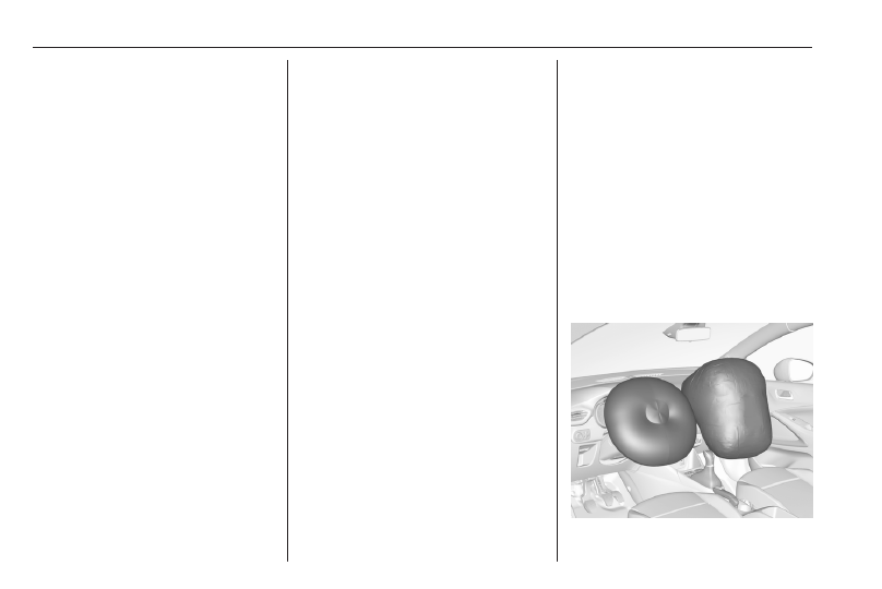
Front airbag system

The front airbag system consists of

one airbag in the steering wheel and

one in the instrument panel on the

front passenger side. These can be

identified by the word AIRBAG.
The front airbag system is triggered in

the event of a front-end impact of a

certain severity. The ignition must be

switched on.
Seats, restraints

39

The inflated airbags cushion the

impact, thereby reducing the risk of

injury to the upper body and head of

the front seat occupants

considerably.

9

Warning

Optimum protection is only

provided when the seat is in the

proper position.
Seat position 

3

 27.

Keep the area in which the airbag

inflates clear of obstructions.
Fit the seat belt correctly and

engage securely. Only then is the

airbag able to protect.

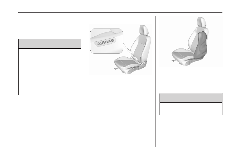
Side airbag system

The side airbag system consists of an

airbag in each front seat backrest.

This can be identified by the word

AIRBAG.
The side airbag system is triggered in

the event of a side impact of a certain

severity. The ignition must be

switched on.

The inflated airbags cushion the

impact, thereby reducing the risk of

injury to the upper body and pelvis in

the event of a side-on collision

considerably.

9

Warning

Keep the area in which the airbag

inflates clear of obstructions.

Notice

Only use protective seat covers that

have been approved for the vehicle.

Be careful not to cover the airbags.

40

Seats, restraints

Curtain airbag system

The curtain airbag system consists of

an airbag in the roof frame on each

side. This can be identified by the

word AIRBAG on the roof pillars.
The curtain airbag system is triggered

in the event of a side-on impact of a

certain severity. The ignition must be

switched on.

The inflated airbags cushion the

impact, thereby reducing the risk of

injury to the head in the event of a

side-on impact considerably.

9

Warning

Keep the area in which the airbag

inflates clear of obstructions.
The hooks on the handles in the

roof frame are only suitable for

hanging up light articles of

clothing, without coat hangers. Do

not keep any items in these

clothes.

Airbag deactivation

The front passenger airbag system

must be deactivated for child restraint

system on the passenger seat

according to the instructions in the

table 

3

 45. The side airbag and

curtain airbag systems, the belt

pretensioners and all driver airbag

systems will remain active.

The front passenger airbag system

can be deactivated via a key-

operated switch on the passenger

side in the glovebox.
Use the ignition key to choose the

position:

*

OFF : front passenger airbag is

deactivated and will not

inflate in the event of a

collision. Control indicator

*

OFF illuminates

continuously in the centre

console

Ó

ON : front passenger airbag is

active

Seats, restraints

41

9

Danger

Deactivate passenger airbag only

in combination with the use of a

child restraint system, subject to

the instructions and restrictions in

the table 

3

 45.

Otherwise, there is a risk of fatal

injury for a person occupying a

seat with a deactivated front

passenger airbag.

If the control indicator 

Ó

ON

illuminates for approx. 60 seconds

after the ignition is switched on, the

front passenger airbag system will

inflate in the event of a collision.
If the control indicator 

*

OFF

illuminates after the ignition is

switched on, the front passenger

airbag system is deactivated. It stays

on while the airbag is deactivated.
If both control indicators are

illuminated at the same time, there is

a system failure. The status of the

system is not discernible, therefore

no person is allowed to occupy the

front passenger seat. Contact a

workshop immediately.
Consult a workshop immediately if

neither of the two control indicators

are illuminated.
Change status only when the vehicle

is stopped with the ignition off.
Control indicator for airbag

deactivation 

3

 70.

Child restraints

Child restraint systems

9

Danger

Make sure that children below

sufficient size and weight are

protected using a suitable child

restraint system. Never place a

child on the lap.

9

Danger

If using a rear-facing child restraint

system on the front passenger

seat, the airbag system for the

front passenger seat must be

deactivated. This also applies to

certain forward-facing child

restraint systems as indicated in

the tables 

3

 45.

Airbag deactivation 

3

 40.

Airbag label 

3

 35.

42

Seats, restraints

We recommend a child restraint

system which is tailored specifically to

the vehicle. For further information,

contact your workshop.
In case of any interference of the child

restraint system with vehicle seat

head restraint, adjust or remove the

corresponding head restraint 

3

 26.

When a child restraint system is being

used, pay attention to the following

usage and installation instructions

and also those supplied with the child

restraint system. The given

restrictions in the table refer to a test

body, which is the maximum

envelope of all existing child restraint

systems. Make sure that the front

seats do not interfere with the used

child restraint system.
Always comply with local or national

regulations. In some countries, the

use of child restraint systems is

forbidden on certain seats.
Only drive with the driver seat

correctly adjusted 

3

 27.

Child restraint systems can be

fastened with:

● Three-point seat belt
● ISOFIX brackets
● Top-tether anchor

Three-point seat belt

Child restraint systems can be

fastened by using a three-point seat

belt. After fastening the child restraint

system the seat belt has to be

tightened 

3

 45.

ISOFIX brackets

Fasten vehicle-approved ISOFIX

child restraint systems to the ISOFIX

brackets. Specific vehicle ISOFIX

child restraint system positions are

marked in the ISOFIX table 

3

 45.

ISOFIX brackets are indicated by a

label on the backrest. To get access

to the ISOFIX brackets, first pull the

zipper.
An i-Size child restraint system is an

universal ISOFIX child restraint

system according UN Regulation No.

129.
All i-Size child restraint systems can

be used on any vehicle seat suitable

for i-Size, i-Size table 

3

 45.

Either a Top-tether strap or a support

leg must be used in addition to the

ISOFIX brackets.

i-Size child seats and vehicle seats

with i-Size approval are marked with

i-Size symbol, see illustration.

Seats, restraints

43

Top-tether anchors

Top-tether anchors are marked with

the symbol 

:

 for a child seat.

In addition to the ISOFIX brackets,

fasten the Top-tether strap to the

Top-tether anchors.
ISOFIX child restraint systems of

universal category positions are

marked in the table by IUF 

3

 45.

Selecting the right system

The rear seats are the most

convenient location to fasten a child

restraint system.

Children should travel facing

rearwards in the vehicle as long as

possible. This makes sure that the

child's backbone, which is still very

weak, is under less strain in the event

of an accident. Do not use forward

facing child restraint system at all

seats when child's weight is below 13

kg.
Suitable are child restraint systems

that comply with valid UN ECE

regulations. Check local laws and

regulations for mandatory use of child

restraint systems.
The following child restraints are

recommended for the following

weight classes:

● Group 0, Group 0+:

Maxi Cosi Cabriofix with or

without ISOFIX base for children

up to 13 kg

● Group I: Duo Plus with ISOFIX

and Top-tether for children from

9 kg to 18 kg

● Group II, Group III: Kidfix XP with

or without ISOFIX for children

from 15 kg to 36 kg

● Group III: Graco Booster for

children from 22 kg to 36 kg

Ensure that the child restraint system

to be installed is compatible with the

vehicle type.
Child seat at the front: Adjust the front

passenger seat to the highest and

fully back longitudinal position with

the backrest straightened.
Child seat at the rear: Move the

vehicle's front seat forward and

straighten the backrest so that the

legs of the child in the forward facing

or the rearward facing child seat do

not touch the vehicle's front seat.
Follow the child restraint system

manufacturer's instructions to install

the corresponding child restraint

system in the vehicle.
For semi-universal or vehicle specific

child restraint system (ISOFIX or

belted child restraint system), see the

vehicle list provided in the user

manual of the child restraint system.

44

Seats, restraints

Ensure that the mounting location of

the child restraint system within the

vehicle is correct, see following table.
Allow children to enter and exit the

vehicle only on the side facing away

from the traffic.
When the child restraint system is not

in use, secure the seat with a seat belt

or remove it from the vehicle.

Notice

Do not affix anything on the child

restraint systems and do not cover

them with any other materials.
A child restraint system which has

been subjected to stress in an

accident must be replaced.

Seats, restraints

45

Child restraint installation locations

Installation of universal, ISOFIX and i-Size child seats

As required by European regulations, this table gives the options for installing child seats secured using the seat belt and

universally approved as well as the larger ISOFIX and i-Size child seats on seat positions equipped with ISOFIX mountings

in the vehicle.
Yes : Suitable for fitment of the designated catecory of the child restraint system.

No : Not suitable for fitment of the designated catecory of the child restraint system.

Front passenger seat

Rear outer seats

Rear centre seat

Position compatible with a universal child seat 

1)

Yes 

2)


3)


4)

Yes 

3)


5)


6)

Yes 

7)


8)

No

Position compatible with an i-Size child seat

No 

9)

Yes

No 

9)

Position equipped with a top-tether fixing

No 

9)

Yes

No 

9)

Carrycot type of child seat

No 

9)

No

No 

9)

Rearward facing ISOFIX child seat

No 

9)

R3 

7)


8)

No 

9)

Forward facing ISOFIX child seat

No 

9)

F3 

7)


8)

No 

9)

Booster child seat

B3 

9)

B3 

10)

B3 

9)

1)

Universal child seat: chiId seat that can be installed in all vehicles using the seat belt.

2)

To install a "rearward facing" child seat at this seat position, the front passenger's airbag must be deactivated "OFF".

3)

For a seat with height adjustment, set it to the maximum height.

4)

For universal child seat : groups 0, 0+, I

5)

Only a "forward facing" child seat is authorised at this seat position with the front passenger's airbag activated "ON".

6)

For universal child seat: groups II and III only

46

Seats, restraints

7)

Move the respective front seat ahead of the child restraint system forwards and the sliding rear seat backwards as far as necessary.

8)

Adjust the respective headrest as necessary or remove if required.

9)

Seats not fitted with ISOFIX compliant mountings.

10)

Remove the headrest.

Rules:

● A position that is i-Size compatible is also compatible for R1, R2 and F2X, F2, B2.
● A position that is R3 compatible is also compatible for R1, R2 and R2X.
● A position that is R2 compatible is also compatible for R1.
● A position that is F3 compatible is also compatible for F2X and F2.
● A position that is B3 compatible is also compatible for B2.

Size of child restraint fixture (1, 2, 3):

● R1 means rearward facing child restraint fixture for mass group 0 up to 10 kg and mass group 0+ up to 13 kg, age

around 0-1 year.

● R2 means reduced size of rearward facing child restraint fixture for mass group 0+ up to 13 kg and mass group 1

from 9 to 18 kg, age around 2-4 years.

● R3 means full size of rearward facing child restraint fixture for mass group 0+ up to 13 kg and mass group 1 from 9

to 18 kg, age around 2-4 years.

● F2, F2X mean reduced height of forward facing child restraint fixture for mass group 1 from 9 to 18 kg, age around

6-7 years.

● F3 means full height of forward facing child restraint fixture for mass group 1 from 9 to 18 kg, age around 7-10 years.

Storage

47

Storage

Storage compartments ................ 47

Glovebox ................................... 47

Cupholders ................................ 47

Centre console storage ............. 47

Load compartment ....................... 48

Load compartment cover ........... 50

Rear floor storage cover ............ 51

Lashing eyes ............................. 52

Warning triangle ........................ 52

First aid kit ................................. 52

Roof rack system ......................... 53

Roof rack ................................... 53

Loading information ..................... 54

Storage compartments

9

Warning

Do not store heavy or sharp

objects in the storage

compartments.

Glovebox

The glovebox should be closed whilst

driving.

Cupholders

Cupholders are located in the centre

console.

Centre console storage

The storage container can be used to

store small items.

48

Storage

Depending on the version, the

storage compartment is located

under a cover.

Load compartment

The rear seat backrest is divided in

two parts. Both parts can be folded

down.

9

Warning

When folding up, ensure that

backrests are securely locked in

position before driving. Failure to

do so may result in personal injury

or damage to the load or vehicle in

the event of hard braking or a

collision.

Before folding rear seat backrests,

execute the following if necessary:

● Remove the load compartment

cover 

3

 50.

● Press and hold the catch to push

the head restraints down 

3

 26.

● Insert the seat belts in the guiding

latches.

Load compartment cover 

3

 50.

Head restraints 

3

 26.

Storage

49

Load compartment extension

(version with lever)

● Pull the release lever on one or

both outer sides and fold down

the backrests onto the seat

cushion.

● To fold up, raise the backrests

and guide them into an upright

position until they engage

audibly.

The backrests are properly

engaged when the red mark near

the release lever is no longer

visible.

Load compartment extension

(version with loop)

● Move both rear seats to the most

rearward position 

3

 31.

● Fold up rear armrest before

folding down the relevant part of

the backrest. Otherwise this part

of the backrest cannot be folded

down.

● Pull the loop and fold down the

backrest onto the seat cushion.

● To fold up, raise the backrests

and guide them into an upright

position until they engage

audibly.

50

Storage

Folding rear armrest

Pull the loop to fold down the rear

armrest.

The armrest can also be folded down

from the load compartment by pulling

the loop and pushing the centre

backrest.
The centre backrest is properly

engaged when the red mark on the

loop is no longer visible.

Load compartment cover

Do not place any objects on the cover.

Removing cover

Unhook retaining straps from tailgate.

Lift cover, slightly angle and turn it.
Remove the cover.

Stowing

Storage

51

The load compartment cover can be

stored behind the rear seat backrests.
Unhook retaining straps and lift the

cover backwards until it unlatches.

Then slide it down in the guides

behind the seat backrests.

Fitting cover

Engage cover in side guides and fold

downwards. Attach the retaining

straps to the tailgate.

Rear floor storage cover

Raise cover at the recess to gain

access to emergency breakdown

equipment.

Tyre repair kit 

3

 253.

Spare wheel 

3

 258.

Double load floor

The double load floor can be inserted

in the load compartment in two

positions:

● lower position above the rear

floor storage cover

● upper position interlocked with

the grab handle into back panel

trim

To remove, press the handle to

unlock the load floor and lift it up while

using the handle.
If mounted in the upper position, the

space between the load floor and the

spare wheel well cover can be used

as a storage compartment.
In this position, if the rear seat

backrests are folded forwards, an

almost completely flat load bay is

created.
In the upper position, the double load

floor is able to withstand a maximum

load of 100 kg. In the lower position,

the double load floor is able to

withstand the maximum permissible

load.

52

Storage

Lashing eyes

The lashing eyes are designed to

secure items against slippage, e.g.

using lashing straps or luggage net.

Warning triangle

Stow the warning triangle in the space

at the rear of the load compartment

and secure it with the Velcro

®

fastener.

First aid kit

Fold down the cover on the left side

of the load compartment.

Storage

53

Stow the first aid kit in the storage

compartment.

Roof rack system

Roof rack

For safety reasons and to avoid

damage to the roof, the vehicle-

approved roof rack system is

recommended.
Follow the installation instructions

and remove the roof rack when not in

use.

Mounting roof rack

Open all doors.
Mounting points are located in each

door frame of the vehicle body.

Detach the cover from each mounting

point and fasten the roof rack with the

attached screws.

54

Storage

Loading information

9

Warning

Always make sure that the load in

the vehicle is securely stowed.

Otherwise objects can be thrown

around inside the vehicle and

cause personal injury or damage

to the load or car.

● Heavy objects in the load

compartment should be placed

against the seat backrests. Make

sure that the backrests are

securely engaged 

3

 48. If objects

can be stacked, heavier objects

should be placed at the bottom.

● Prevent sliding of loose objects

by securing them with straps

attached to the lashing eyes

3

 52.

● Do not allow the load to protrude

above the upper edge of the

backrests.

● Do not place any objects on the

load compartment cover or the

instrument panel, and do not

cover the sensor on top of the

instrument panel.

● The load must not obstruct the

operation of the pedals, parking

brake and gear selector, or

hinder the freedom of movement

of the driver. Do not place any

unsecured objects in the interior.

● Do not drive with an open load

compartment.

● The payload is the difference

between the permitted gross

vehicle weight (see identification

plate 

3

 275) and the EC kerb

weight.

To calculate the payload, enter

the data for your vehicle in the

weights table at the front of this

manual.
The EC kerb weight includes

weights for the driver (68 kg),

luggage (7 kg) and all fluids (fuel

tank 90% full).
Optional equipment and

accessories increase the kerb

weight.

● Driving with a roof load increases

the sensitivity of the vehicle to

cross-winds and has a

detrimental effect on vehicle

handling due to the vehicle's

higher centre of gravity.

Distribute the load evenly and

secure it properly with retaining

straps. Adjust the tyre pressure

and vehicle speed according to

the load conditions. Check and

retighten the straps frequently.
Do not drive faster than 75 mph.
The permissible roof load is

60 kg. The roof load is the

combined weight of the roof rack

and the load.

Instruments and controls

55

Instruments and

controls

Instrument panel overview ........... 56
Controls ....................................... 58

Steering wheel adjustment ........ 58

Steering wheel controls ............. 58

Heated steering wheel ............... 58

Horn ........................................... 59

Windscreen wiper and washer . . 59

Rear window wiper and

washer ...................................... 61

Outside temperature .................. 61

Clock ......................................... 62

Power outlets ............................. 62

Inductive charging ..................... 63

Cigarette lighter ......................... 64

Ashtrays .................................... 64

Warning lights, gauges and indi‐

cators ........................................... 64

Speedometer ............................. 64

Odometer .................................. 65

Trip odometer ............................ 65

Tachometer ............................... 65

Fuel gauge ................................ 66

Engine coolant temperature

gauge ....................................... 66

Engine oil level monitor ............. 66

Service display .......................... 67

Control indicators ...................... 68

Turn lights .................................. 69

Seat belt reminder ..................... 70

Airbag and belt tensioners ......... 70

Airbag deactivation .................... 70

Charging system ....................... 71

Malfunction indicator light .......... 71

Service vehicle soon ................. 71

Stop engine ............................... 71

System check ............................ 71

Brake and clutch system ........... 72

Parking brake ............................ 72

Antilock brake system (ABS) ..... 72

Gear shifting .............................. 72

Descent control system ............. 73

Lane departure warning ............ 73

Electronic Stability Control and

Traction Control system ........... 73

Electronic Stability Control and

Traction Control system off ...... 73

Engine coolant temperature ...... 73

Preheating ................................. 73

Exhaust filter .............................. 73

AdBlue ....................................... 74

Deflation detection system ........ 74

Engine oil pressure .................... 74

Low fuel ..................................... 75

Autostop .................................... 75

Exterior light .............................. 75

Low beam .................................. 75

High beam ................................. 75

High beam assist ....................... 75

Front fog lights ........................... 75

Rear fog light ............................. 75

Rain sensor ............................... 75

Cruise control ............................ 75

Side blind spot alert ................... 75

Active emergency braking ......... 75

Speed limiter ............................. 76

Door open .................................. 76

Displays ....................................... 76

Driver Information Centre .......... 76

Info Display ................................ 79

Head-up display ........................ 81

Vehicle messages ........................ 82

Warning chimes ......................... 83

Vehicle personalisation ................ 83
Telematics services ..................... 84

Emergency call .......................... 84

Vauxhall Connect ...................... 85

ERA GLONASS ......................... 85

56

Instruments and controls

Instrument panel overview

Instruments and controls

57

1

Power windows ..................... 22

2

Exterior mirrors ..................... 19

3

Cruise control  ..................... 192
Speed limiter ....................... 195
Heated steering wheel  ......... 58

4

Turn lights ............................. 91
Headlight flash ...................... 89
High beam ............................. 88
High beam assist  ................. 88
Exit lighting  ........................... 94
Parking lights ........................ 92
Buttons for Driver

Information Centre ................ 76

5

Side air vents ...................... 169

6

Instruments  .......................... 64
Driver Information Centre ...... 76

7

Infotainment controls  ........... 58

8

Windscreen wiper and

washer, rear wiper and

washer  ................................. 59

9

Head-up display .................... 81

10 Air vents  ............................. 169

11 Hazard warning flashers  ...... 90
12 Info Display  .......................... 79
13 Air vent ................................ 169
14 Sun sensor .......................... 164
15 Central locking system .......... 10
16 Glovebox  .............................. 47
17 Controls for Info Display

operation ............................... 79

18 Climate control system ........ 160
19 USB port  .............................. 62
20 Electronic Stability Control

and Traction Control ........... 188
Lane departure warning  ..... 218
Stop-start system ................ 175
Parking assist  ..................... 203
Advanced parking assist  .... 206
Electric child locks  ................ 14

21 Power outlet .......................... 62
22 Selector lever ...................... 183
23 Parking brake ...................... 187
24 Power button ....................... 173
25 Ignition switch ..................... 172
26 Steering wheel adjustment  . . 58
27 Horn  ..................................... 59

28 Bonnet release lever  .......... 234
29 Storage ................................. 47
30 Head-up display .................... 81
31 Light switch  .......................... 87

Headlight range

adjustment  ........................... 89
Front fog lights  ..................... 91
Rear fog light  ........................ 92
Instrument illumination  ......... 93

58

Instruments and controls

Controls

Steering wheel adjustment

Unlock lever, adjust steering wheel,

then engage lever and ensure it is

fully locked.
Do not adjust steering wheel unless

vehicle is stationary and steering

wheel lock has been released.

Steering wheel controls

Cruise control and speed limiter are

operated via the controls on the left

side of the steering wheel.
On the same side is located the

switch for the heated steering wheel.
Infotainment system can be operated

via the controls on the right side of the

steering wheel.
Driver assistance systems 

3

 192.

Further information is available in the

Infotainment system section.
Heated steering wheel 

3

 58.

Heated steering wheel

Activate heating by pressing 

*

.

Activation is indicated by the LED in

the button.
Heating is operational when the

engine is running and during an

Autostop.
The heating works only when the

outside temperature is below 20 °C.
Stop-start system 

3

 175.

Instruments and controls

59

Horn

Press 

j

.

Windscreen wiper and

washer

Windscreen wiper with adjustable

wiper frequency

HI

: fast

LO : slow

INT : interval wiping

OFF : off

1x

: single wipe

Do not use if the windscreen is frozen.
Switch off in car washes.

To activate interval wiping mode the

next time ignition is switched on,

press the lever downwards to position

OFF and back to INT.

Adjustable wiper frequency

Wiper lever in position INT.
Turn the adjuster wheel to adjust the

wiping frequency.

60

Instruments and controls

Windscreen wiper with rain

sensor

HI

: fast

LO

: slow

AUTO : automatic wiping with rain

sensor

OFF : off

1x

: single wipe

In AUTO position, the rain sensor

detects the amount of water on the

windscreen and automatically

regulates the frequency of the

windscreen wiper. If ignition is

switched off, automatic wiping mode

is deactivated. To activate automatic

wiping mode the next time ignition is

switched on, press the lever

downwards to position OFF and back

to AUTO.
Do not use if the windscreen is frozen.
Switch off in car washes.

Adjustable sensitivity of the rain

sensor

Wiper lever in position AUTO.
Turn the adjuster wheel to adjust the

sensitivity of the rain sensor.
Make sure the sensor is not blocked

3

 21.

Control indicator 

<


3

 75.

Windscreen washer

Pull lever. Washer fluid is sprayed

onto the windscreen and the wiper

wipes a few times.
Washer fluid 

3

 236.

Instruments and controls

61

Rear window wiper and

washer

Rear window wiper

OFF : off

INT : intermittent operation
Do not use if the rear window is

frozen.
Switch off in car washes.
The rear window wiper comes on

automatically when the windscreen

wiper is switched on and reverse gear

is engaged.

Activation or deactivation of this

function can be changed in the

Vehicle personalisation menu 

3

 83.

Rear window washer

Push lever.
Washer fluid is sprayed onto the rear

window and the wiper wipes a few

times.
The rear window washer system is

deactivated when the fluid level is

low.
Washer fluid 

3

 236.

Outside temperature

A drop in temperature is indicated

immediately and a rise in temperature

after a time delay.

Illustration shows an example.
If outside temperature drops to 3 °C,

a warning message is displayed in the

Driver Information Centre.

9

Warning

The road surface may already be

icy even though the display

indicates a few degrees above 0

°C.

62

Instruments and controls

Clock

Date and time are shown in the

Info Display 

3

 79.

Setting date and time, see

Infotainment system section.

Power outlets

A 12 V power outlet is located in the

centre console.

Another power outlet is located in the

console between the front seats.
Do not exceed the maximum power

consumption of 120 W.
With ignition off, the power outlet is

deactivated. Additionally, the power

outlet is deactivated in the event of

low vehicle battery voltage.
Electrical accessories that are

connected must comply with the

electromagnetic compatibility

requirements laid down in

DIN VDE 40 839.
Do not connect any current-delivering

accessories, e.g. electrical charging

devices or batteries.

Do not damage the outlets by using

unsuitable plugs.
Stop-start system 

3

 175.

USB charging port

One or two USB ports are prepared

for charging devices.
When two USB ports are available,

the upper USB port can be used to

connect a phone for phone projection.

Notice

The sockets must always be kept

clean and dry.

USB port and phone projection see

Infotainment system section.

Instruments and controls

63

Inductive charging

9

Warning

Inductive charging can affect the

operation of implanted

pacemakers or other medical

devices. If applicable, seek

medical advice before using the

inductive charging device.

9

Warning

Remove any metal objects from

the charging device before

charging a mobile device, as these

objects could become very hot.

To charge a mobile device:

1. Remove all objects from the

charging device.

2. Place the mobile device with the

display facing upwards on the

charging device.

3. LED illuminates green, when

mobile device is charging.

The mobile device must be smaller

than 7 cm by 15 cm to fit into the

charging device.
PMA or Qi compatible mobile devices

can be charged inductively.

On some mobile devices, a back

cover with an integrated coil or a

jacket may be required to use

inductive charging.
Protective cover for the mobile device

could have impact on the inductive

charging.
LED illuminates yellow, when

● metall objects have been

detected in the charging area

● mobile device was not placed

properly.

In the case that the mobile device is

not charging properly:

1. Remove the mobile device from

the charging device.

2. Rotate the mobile device by 180°.
3. Wait three seconds after the LED

has extinguished and place the

mobile device on the charging

device again.

64

Instruments and controls

Cigarette lighter

Press in the cigarette lighter. It

switches off automatically once the

element is glowing. Pull out the

cigarette lighter.

Ashtrays

Caution

To be used only for ash and not for

combustible rubbish.

A portable ashtray can be placed in

the cupholders.

Warning lights, gauges

and indicators

Speedometer

Indicates vehicle speed.

Instruments and controls

65

Odometer

The total recorded distance is

displayed in miles.

Trip odometer

The recorded distance since the last

reset is displayed in the Driver

Information Centre.

Monochrome display

Trip odometer counts up to

9,999.9 miles without automatic

reset.
Press 

L

 for 2 seconds to reset trip

odometer.

Colour display

Trip odometer counts up to

1,999.9 miles and resets then

automatically.
Press 

L

 for 2 seconds to reset trip

odometer.

The trip / fuel information menu

provides additionally two trip counter

3

 76.

Tachometer

Displays the engine speed.
Drive in a low engine speed range for

each gear as much as possible.
A red marker indicates the beginning

of the warning zone of excessive

revolutions. For Diesel engines, the

warning zone starts at 5000

revolutions per minute. For petrol

engines, the warning zone starts at

7000 revolutions per minute.

66

Instruments and controls

Caution

If the needle is in the red warning

zone, the maximum permitted

engine speed is exceeded. Engine

at risk.

Fuel gauge

Displays the fuel level in the tank.
Control indicator 

o

 illuminates if the

level in the tank is low.
Never run the fuel tank dry.
The top-up quantity may be less than

the specified fuel tank capacity, due

to the remaining fuel in the tank.

Engine coolant temperature

gauge

Displays the coolant temperature.
50 : engine operating temperature

not yet reached

90 : normal operating temperature

130 : temperature too high
Control indicator 

o

 illuminates if

engine coolant temperature is too

high.

Caution

If engine coolant temperature is

too high, stop vehicle, switch off

engine. Danger to engine. Check

coolant level.

Engine oil level monitor

The state of the engine oil level is

displayed in the Driver Information

Centre for a few seconds following

the service information after switching

on the ignition.
A proper state of engine oil level is

indicated by the message Oil level

correct.
If engine oil level is low, 

I

 flashes

and Oil level incorrect is indicated,

accompanied by the 

C

 indicator.

Confirm engine oil level by using the

dipstick and top up engine oil

respectively.
Engine oil 

3

 234.

A fault of measurement is indicated

by the message Oil level

measurement invalid. Check engine

oil level manually by using the

dipstick.

Instruments and controls

67

Service display

The service system informs when to

change the engine oil and filter or a

vehicle service is required. Based on

driving conditions, the interval at

which an engine oil and filter change

is required can vary considerably.
Service information 

3

 270.

A required service due is displayed in

the Driver Information Centre for

seven seconds after switching on the

ignition.
If no service is required for the next

1800 miles or more no service

information appears in the display.
If service is required within the next

1800 miles, the remaining distance or

time duration is indicated for several

seconds. Simultaneously 

C

illuminates permanently as reminder.
If service is required in less than

600 miles, 

C

 flashes and then

illuminates permanently. Remaining

distance or time duration is indicated

for several seconds.

Overdued service is indicated by a

message in the Driver Information

Centre which indicates the overdued

distance. 

C

 flashes and then

illuminates permanently until service

is executed.

Reset of service interval

After each service, the service

indicator must be reset to ensure

proper functionality. It is

recommended to seek the assistance

of a workshop.
Operate as following:

● switch off ignition
● press and hold button 

M

 or

CHECK

● switch on ignition, the distance

indication begins a countdown

● when the display indicates =0,

release the button

The symbol 

C

 disappears.

Retrieving service information

To retrieve the status of the service

information at any time press left

button underneath the Driver

Information Centre.

Or

68

Instruments and controls

The service information is displayed

for a few seconds.
Service information 

3

 270.

Control indicators

The control indicators described are

not present in all vehicles. The

description applies to all instrument

versions.
Depending on the equipment, the

position of the control indicators may

vary. When the ignition is switched

on, most control indicators will

illuminate briefly as a functionality

test.

The control indicator colours mean:
red

: danger, important reminder

yellow : warning, information, fault

green : confirmation of activation

blue

: confirmation of activation

white : confirmation of activation

grey

: system paused, at least one

system limitation has been

detected

Control indicators are located in the

Driver Information Centre.
Driver Information Centre 

3

 76.

Overview

The numbers in the overview table

indicate what to do, when a control

indicator illuminates or flashes.
1 : only for information

2 : information and warning

3 : seek the assistance of a

workshop

4 : stop engine and seek the

assistance of a workshop

5 : have the cause of the fault

remedied immediately by a

workshop

6 : stop vehicle, do not continue the

journey and seek the assistance

of a workshop

;

 / 

:

1

Turn lights 

3

 69

a

2

Seat belt reminder

3

 70

d

5

Airbag and belt

tensioners 

3

 70

H

2

Airbag activated 

3

 70

g

2

Airbag deactivated

3

 70

S

4

Charging system

3

 71

W

5

Malfunction indicator

light 

3

 71

C

5

Service vehicle soon

3

 71

+

4

Stop engine 

3

 71

X

4

System check 

3

 71

Instruments and controls

69

h

6

Brake and clutch system

3

 72

j

1 /

5

Parking brake 

3

 72

i

2

Antilock brake system

(ABS) 

3

 72

Y

1

Gear shifting 

3

 72

ò

1

Descent control system

3

 73

)

1

Lane departure warning

3

 73

J

2 /

5

Electronic Stability

Control and Traction

Control system 

3

 73

K

2

Electronic Stability

Control and Traction

Control system off

3

 73

V

4

Engine coolant temper‐

ature high 

3

 73

z

1

Preheating 

3

 73

%

2 /

3

Exhaust filter 

3

 73

B

1

AdBlue 

3

 74

q

2 /

3

Deflation detection

system 

3

 74

T

4

Engine oil pressure

3

 74

r

2

Low fuel 

3

 75

n

1

Autostop 

3

 75

F

1

Exterior light 

3

 75

D

1

Low beam 

3

 75

A

1

High beam 

3

 75

N

1

High beam assist

3

 75

G

1

Front fog lights 

3

 75

H

1

Rear fog light 

3

 75

y

1

Rain sensor 

3

 75

m

1

Cruise control 

3

 75

B

1

Side blind spot alert

3

 75

m

2 /

3

Active emergency

braking 

3

 75

ß

1

Speed limiter 

3

 76

X

2

Door open 

3

 76

Turn lights

O

 illuminates or flashes green.

Illuminates briefly

The parking lights are switched on.

Flashes

A turn light or the hazard warning

flashers are activated.
Rapid flashing: failure of a turn light or

associated fuse.
This includes turn lights connected to

the socket of the towing equipment.
Bulb replacement 

3

 240.

Fuses 

3

 248.

Turn lights 

3

 91.


Content      ..      1      2      3      ..