Nortel Communication Server 1000. Installation And Commissioning Manual (2008) - page 3
Installing a Signaling Server
Page 201 of 466
Figure 72
IP Phone firmware
CS 1000 Signaling Server Software Install Tool (sse-x.xx.xx)
=====================================================================
The installation source contains multiple Internet Telephone firmware
files.
Copying /cd0/0603Bxx.bin” to “/u/fw/0603Bxx.bin”.
Copying “/cd0/0602Bxx.bin” to “/u/fw/0602Bxx.bin”.
Copying “/cd0/0604Dxx.bin” to “/u/fw/0604Dxx.bin”.
Figure 73
Voice Gateway Media Card loadware
CS 1000 Signaling Server Software Install Tool (sse-x.xx.xx)
=====================================================================
The installation source contains multiple Voice Gateway Media Card
loadware files.
Copying “/cd0/IPL4xxxx.p2” to “/u/fw/IPL4xxxx.p2”.
Copying “/cd0/IPL4xxxx.sa” to “/u/fw/IPL4xxxx.sa”.
7
After the Signaling Server software and system components are installed,
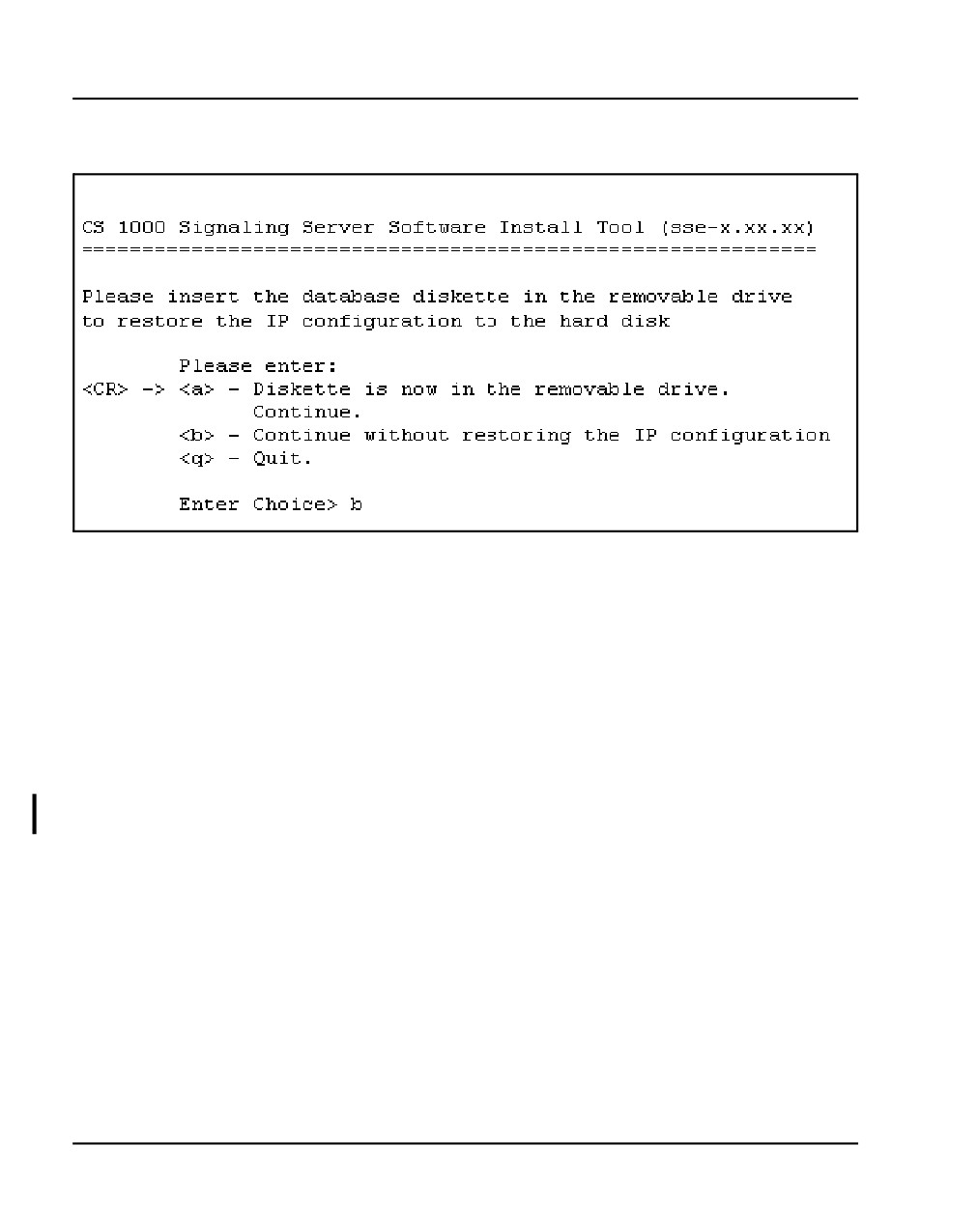
the Restore IP configuration screen appears (Figure 74 on page 202).
Communication Server 1000E Installation and Commissioning
Page 202 of 466
Installing a Signaling Server
Figure 74
Restore IP configuration
8
Do one of the following:
•
If you are migrating a Leader Signaling Server (see "Signaling Server
migration" in Signaling Server: Installation and Commissioning
(NN43001-312),insert the Removable Media Device (RMD) into the
appropriate drive, and press <CR> or enter a to restore the IP
configuration data. After the restore is complete, the following system
message appears:
Done copying IP configuration to disk
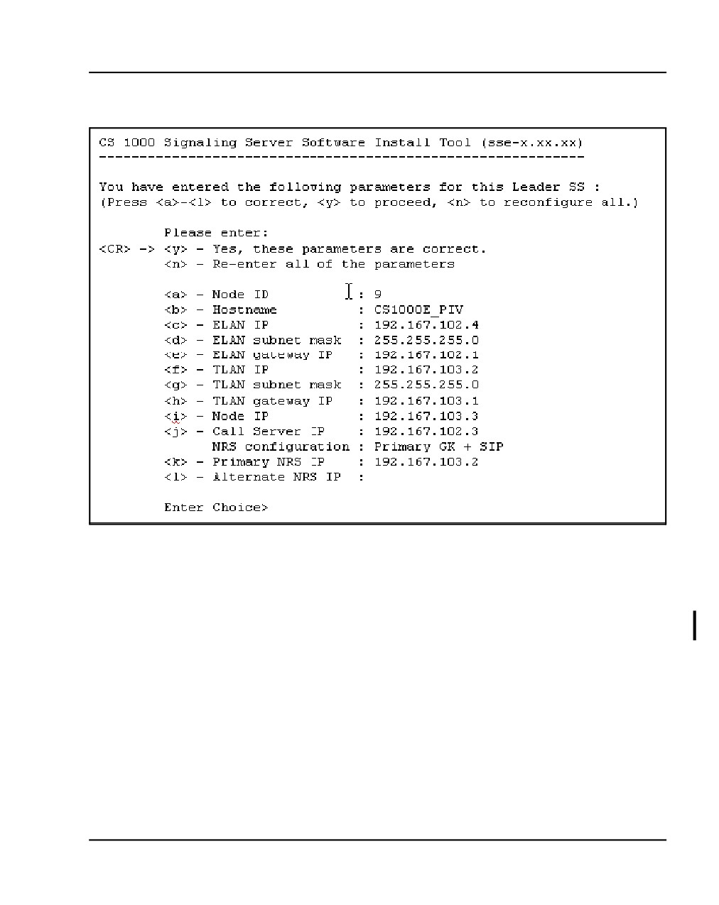
The IP Telephony parameter confirmation screen appears (Figure 75
on page 203). Go to step 12 on page 228.
NN43041-310
Standard 01.11
October 2008
Installing a Signaling Server
Page 203 of 466
Figure 75
IP telephony parameter confirmation
9
If you are installing a new Signaling Server, or you are migrating a
Follower or Standalone Signaling Server (see "Signaling Server
migration" in Signaling Server: Installation and Commissioning
(NN43001-312)), select b to bypass the restoration of IP configuration
data. The Signaling Server role selection screen appears (Figure 76 on
page 204).
Communication Server 1000E Installation and Commissioning
Page 204 of 466
Installing a Signaling Server
Figure 76
Signaling Server role selection
CS 1000 Signaling Server Software Install Tool (sse-x.xx.xx)
=====================================================================
Note: This step will over-write all existing configuration parameters
on this Signaling Server.
Please select the role of this Signaling Server.
If this Signaling Server will be a Leader then its data networking
and IP Telephony parameters must be entered now. (This will pre-
configure the IP Telephony node files.)
If this Signaling Server will be a Follower then its data networking
and IP Telephony parameters must be configured through Element
Manager later.
Please enter:
<CR> -> <a> - Set this Signaling Server as a Leader.
<b> - Set this Signaling Server as a Follower.
<q> - Quit.
Enter Choice>
10
Configure the Signaling Server as Leader or Follower. See Figure 76 on
page 204.
•
If there is already a Leader Signaling Server in the IP Telephony
node, enter b at the prompt to set this Signaling Server as Follower.
The Follower Signaling Server configuration screen appears
(Figure 77 on page 205). Go to step 10 on page 224.
NN43041-310
Standard 01.11
October 2008
Installing a Signaling Server
Page 205 of 466
Figure 77
Follower Signaling Server configuration
CS 1000 Signaling Server Software Install Tool (sse-x.xx.xx)
=======================================================================
This Follower Signaling Server will obtain its data network and IP
telephony configuration from the Leader Signaling Server at boot.
To identify this Signaling Server, please enter a Hostname.
Hostname : SS_Node276_Ldr
•
If there is not already a Leader Signaling Server in the IP Telephony
node, or if the Signaling Server is to be a stand-alone Signaling
Server, enter a at the prompt to configure this Signaling Server as
Leader. The Application configuration screen appears (Figure 78 on
page 205).
Figure 78
Application configuration
CS 1000 Signaling Server Software Install Tool (sse-x.xx.xx)
=====================================================================
Please select the application configuration for this Signaling Server.
Please enter:
<CR> -> <a> - Co-resident (LTPS + VTRK + NRS).
<b> - Stand-alone (NRS only - no Call Server).
<q> - Quit.
Enter Choice>
Communication Server 1000E Installation and Commissioning
Page 206 of 466
Installing a Signaling Server
11
Configure the application configuration for this Signaling Server. See
Figure 78 on page 205.
•
If the IP Phone TPS, Virtual Trunk TPS, and optional Network
Routing Service (NRS) applications are to be enabled on this
Signaling Server, enter a at the prompt to configure this Signaling
Server as a co-resident Signaling Server.
•
If only the NRS is to be enabled on this Signaling Server:
— If this Signaling Server is to be associated with a Call Server,
enter a at the prompt to configure this Signaling Server as a
co-resident Signaling Server. After you have finished installing
the Signaling Server software, you can disable the Set TPS and
Virtual Trunk TPS in Element Manager (refer to Element
Manager: System Administration (NN43001-332)).
— If this Signaling Server is not to be associated with a Call Server,
enter b at the prompt to set this Signaling Server as a
stand-alone Signaling Server.
Depending on the application configuration selected, either the
NRS - Coresident Signaling Server screen or the NRS - Standalone Signaling
Server screen appears.
Figure 79
Network Routing Service (NRS) — co-resident Signaling Server
CS 1000 Signaling Server Software Install Tool (sse-x.xx.xx)
=====================================================================
Please select the Network Routing Service (NRS) configuration for this
Signaling Server.
Please enter:
<CR> -> <a> - H.323 Gatekeeper and SIP Redirect/Proxy Server.
<b> - H.323 Gatekeeper only.
<c> - SIP Redirect/Proxy Server only.
<d> - None.
Enter Choice>
NN43041-310
Standard 01.11
October 2008
Installing a Signaling Server
Page 207 of 466
Figure 80
Network Routing Service (NRS) — stand-alone Signaling Server
CS 1000 Signaling Server Software Install Tool (sse-x.xx.xx)
=====================================================================
Please select the Network Routing Service (NRS) configuration for this
Signaling Server.
Please enter:
<CR> -> <a> - H.323 Gatekeeper and SIP Redirect/Proxy Server.
<b> - H.323 Gatekeeper only.
<c> - SIP Redirect/Proxy Server only.
Enter Choice>
12
Select the Network Routing Service (NRS) to be provided by this
Signaling Server. See Figure 79 on page 206 for a co-resident Signaling
Server or Figure 80 on page 207 for a stand-alone Signaling Server.
•
Enter d if this Signaling Server is configured as a Coresident Leader
and is not providing an NRS. Go to step 13.
•
Press <CR> or enter a if this Signaling Server is to provide an H.323
Gatekeeper and a SIP Redirect/Proxy Server.
•
Enter b if this Signaling Server is to provide only an H.323
Gatekeeper.
•
Enter c if this Signaling Server is to provide only a SIP Redirect/Proxy
Server.Refer to Network Routing Service Installation and
Commissioning (NN43001-564) for more information on the NRS.
Depending on the application configuration selected, either the NRS type:
Coresident Signaling Server screen or the NRS type: Standalone Signaling
Server screen appears.
Communication Server 1000E Installation and Commissioning
Page 208 of 466
Installing a Signaling Server
Figure 81
NRS type — co-resident Signaling Server
CS 1000 Signaling Server Software Install Tool (sse-x.xx.xx)
=====================================================================
Please select the type of Network Routing Service (NRS) for this
Signaling Server.
Please enter:
<CR> -> <a> - Primary.
<b> - Alternate.
<c> - Failsafe.
Enter Choice>
Figure 82
NRS type — stand-alone Signaling Server
CS 1000 Signaling Server Software Install Tool (sse-x.xx.xx)
=====================================================================
Please select the type of Network Routing Service (NRS) for this
Signaling Server.
Please enter:
<CR> -> <a> - Primary.
<b> - Alternate.
Enter Choice>
13
Select the type of NRS to be provided by this Signaling Server. See
Figure 81 for a co-resident Signaling Server.
•
If this Signaling Server is to be the Primary NRS, enter a.
•
If this Signaling Server is to be the Alternate NRS, enter b.
•
If this Signaling Server is not a stand-alone Signaling Server and is
to be the Fail-safe NRS, enter c.
Refer to Network Routing Service Installation and Commissioning
(NN43001-564) for more information on the NRS.
NN43041-310
Standard 01.11
October 2008
Installing a Signaling Server
Page 209 of 466
Depending on whether the Signaling Server is configured as Leader or
Standalone, either the Leader Signaling Server configuration screen
(Figure 83) or the Standalone Signaling Server configuration screen
(Figure 84) appears.
Figure 83
Leader Signaling Server configuration
CS 1000 Signaling Server Software Install Tool (sse-x.xx.xx)
=====================================================================
Please enter the data networking and IP Telephony parameters for
this Leader Signaling Server.
Node ID
: 276
Hostname
: SS_Node276_Ldr
ELAN IP
: 192.168.10.20
ELAN subnet mask: 255.255.255.0
ELAN gateway IP : 192.168.10.1
TLAN IP
: 192.168.20.20
TLAN subnet mask: 255.255.255.0
TLAN gateway IP : 192.168.20.1
Node IP
: 192.168.10.20
Call Server IP
: 192.168.10.10
Communication Server 1000E Installation and Commissioning
Page 210 of 466
Installing a Signaling Server
Figure 84
Stand-alone Signaling Server configuration
CS 1000 Signaling Server Software Install Tool (sse-x.xx.xx)
=====================================================================
Please define the data networking parameters for this Standalone
Signaling Server. Note that the ELAN parameters are necessary for
management access (e.g. SNMP).
Hostname
: SS_SA
ELAN IP
: 192.168.10.20
ELAN subnet mask: 255.255.255.0
ELAN gateway IP : 192.168.10.1
TLAN IP
: 192.168.20.20
TLAN subnet mask: 255.255.255.0
TLAN gateway IP : 192.168.20.1
14
Enter the data networking and IP telephony parameters for the Signaling
Server, as prompted. The IP information applies to a temporary IP
Telephony node, to ensure that the existing node is not affected. The
entry of data networking and IP telephony parameters also preconfigures
the IP Telephony node files. After the Signaling Server software
installation, the node files are imported into Element Manager for further
configuration (see "Importing IP Telephony nodes" in Signaling Server:
Installation and Commissioning (NN43001-312)).
•
If this is a Leader Signaling Server, enter the parameters for the
Node, ELAN network interface, TLAN network interface, and Call
Server as required.
— If installing the Signaling Server at an office that is not a branch
office, enter the ELAN network interface IP address of the Call
Server.
— If installing the Signaling Server at a branch office, enter the
ELAN network interface IP address of the MG 1000B Core.
•
If this is a Follower Signaling Server, enter the Hostname of the
Leader Signaling Server. Then go to step 16 on page 213.
•
If this is a stand-alone Signaling Server and not associated with a
Call Server (that is, b was selected in step 11 on page 206), enter the
NN43041-310
Standard 01.11
October 2008
Installing a Signaling Server
Page 211 of 466
TLAN subnet parameters as required. The Call Server IP address is
automatically set to 0.0.0.0.
Depending on whether the Signaling Server is configured as Primary,
Alternate, or Standalone, either the Primary NRS IP address screen,
the Alternate NRS IP address screen, or both (in succession) appear.
Both screens appear in succession for a Standalone Signaling
Server.
Figure 85
Primary NRS IP address
CS 1000 Signaling Server Software Install Tool (sse-x.xx.xx)
=====================================================================
Please enter the Primary NRS IP Address:
Primary NRS IP
:
Figure 86
Alternate NRS IP address
CS 1000 Signaling Server Software Install Tool (sse-x.xx.xx)
=====================================================================
Please enter the Alternate NRS IP Address:
Alternate NRS IP :
15
Enter the Primary NRS IP address or the Alternate NRS IP address,
depending on the option entered in step 12 on page 207 or step 13 on
page 208.
•
If a was entered in step 13, you can enter the address of the Alternate
NRS if you know it, but it is not required. See.
•
If b was entered in step 13, enter the address of the Primary NRS.
•
If c was entered in step 13:
— Enter the address of the Primary NRS.
— Enter the address of the Alternate NRS.
•
If d was entered in step 12:
Communication Server 1000E Installation and Commissioning
Page 212 of 466
Installing a Signaling Server
— Enter the address of the Primary NRS (optional).
— If you did enter the address of the Primary NRS, enter the
address of the Alternate NRS (also optional).
The Gatekeeper configuration can be updated later using Element
Manager.
The IP Telephony parameter confirmation screen appears (Figure 87).
Figure 87
IP Telephony parameter configuration
CS 1000 Signaling Server Software Install Tool (sse-x.xx.xx)
=====================================================================
You have entered the following parameters for this Leader
Signaling Server:
Node ID
: 276
Hostname
: SS_Node276_Ldr
ELAN IP
: 192.168.20.100
ELAN subnet mask: 255.255.255.0
ELAN gateway IP : 192.168.10.1
TLAN IP
: 192.168.20.20
TLAN subnet mask: 255.255.255.0
TLAN gateway IP : 192.168.20.1
Node IP
: 192.168.20.100
Call Server IP
: 192.168.10.10
NRS configuration: Alternate GK + SIP
Primary NRS IP
: 192.168.20.10
Alternate NRS IP : 192.168.20.24
Please enter:
<CR> -> <y> - Yes, these parameters are correct.
<n> - No, these parameters are not correct.
Enter Choice>
NN43041-310
Standard 01.11
October 2008
Installing a Signaling Server
Page 213 of 466
16
Enter <CR> or y to confirm the parameters.
The example in Figure 87 on page 212 is for a Leader Signaling Server
configured with an Alternate H.323 and SIP NRS. The confirmation
screens for a Follower and stand-alone Signaling Server are similar,
showing the same list of parameters, specifically:
•
The configuration screen for the Follower Signaling Server displays
only the value for the Hostname parameter; all other values are
blank.
•
The configuration screen for the stand-alone Signaling Server
displays values for the Hostname, ELAN network interface, TLAN
network interface, and NRS parameters. The Node ID field is set to
0. The Call Server IP field is set to 0.0.0.0.
After you confirm the IP configuration, the following system messages
appear:
For future reference, the ELAN MAC address is:
“00:02:b3:c5:5l:c6”.
Wrote config file "/u/config/bootp.tab".
Wrote config file "/boot/nvram.sys".
Wrote config file "/u/config/config.ini".
Wrote config file "/u/config/nrsconf.xml".
Note: You must configure the ELAN network interface MAC address for
the newly installed Signaling Server in the Element Manager node
configuration web page.
17
To complete the installation, the Installation Status Summary screen
appears as shown in Figure 88 on page 214.
Communication Server 1000E Installation and Commissioning

Page 214 of 466
Installing a Signaling Server
Figure 88
Installation Status Summary
18
Press <CR> to exit to the Main Menu (see Figure 89 on page 215). Enter
q at the Main Menu to quit the installation process. Figure 90 on page 215
appears. Enter q again.
NN43041-310
Standard 01.11
October 2008
Installing a Signaling Server
Page 215 of 466
Figure 89
Install Tool Main Menu
CS 1000 Signaling Server Software Install Tool (sse-x.xx.xx)
=====================================================================
M A I N
M E N U
The Install Tool will install Signaling Server software and related
files. You will be prompted throughout the installation.
Please enter:
<CR> -> <a> - To perform a complete installation/upgrade (Signaling
Server s/w, IP Phone f/w, Voice Gateway Media
Card l/w, basic Signaling Server configuration).
<b> - To install/upgrade Signaling Server software only.
<c> - To copy IP Phone firmware only.
<d> - To copy Voice Gateway Media Card loadware only.
<e> - To perform basic Signaling Server configuration only.
<t> - To go to the Tools Menu.
<q> - Quit.
Enter Choice>
Figure 90
Quit
CS 1000 Signaling Server Software Install Tool (sse-x.xx.xx)
=====================================================================
You have selected to quit the Install Tool.
Before quitting and rebooting the system, remove all disks (floppy,
CDROM) from the drives.
Please enter:
<CR> -> <m> - Return to previous menu.
<q> - Quit and reboot the system.
Enter Choice> q
Communication Server 1000E Installation and Commissioning
Page 216 of 466
Installing a Signaling Server
19
Remove the Signaling Server Software CD or the Signaling Server
Software CF Card (as appropriate) from the RMD drive of the Signaling
Server and enter q to close/terminate the Installation Tool and reboot the
system. The following system messages appear:
Removing temporary file "/u/disk.sys".
Rebooting system
End of Procedure
First boot of a new Nortel CP PM Signaling Server
Nortel CP PM Signaling Servers have CS 1000 Release 5.0 software,
applications, operating system, and web files preloaded on the hard drive
when they are shipped. On the first boot of a Nortel CP PM Signaling Server,
the Signaling Server Software Installation Tool prompts you to enter basic
system configuration parameters.
Before you begin
Before booting the new Nortel CP PM Signaling Server for the first time and
entering basic system configuration parameters, you must perform the
following tasks:
•
Install and connect the Signaling Server (refer to “Installing the CP PM
Signaling Server hardware” on page 177).
•
Obtain the network and IP Telephony data for the Signaling Server from
your Planning and Engineering group:
- node ID for the IP Telephony node
- node IP address for the IP Telephony node
- hostname for the Signaling Server
- ELAN network interface IP address, Subnet mask, and
Gateway
- TLAN network interface IP address, Subnet mask, and
Gateway
- ELAN network interface IP address of the Call Server
NN43041-310
Standard 01.11
October 2008
Installing a Signaling Server
Page 217 of 466
– Primary and Alternate NRS IP addresses for this networked
system. Refer to IP Peer Networking: Installation and
Commissioning (NN43001-313)
- NRS role, if applicable. Refer to IP Peer Networking:
Installation and Commissioning (NN43001-313)
Entering basic system parameters
Procedure 44
Entering basic system configuration parameters
1
Press the RST button on the faceplate of the CP PM Signaling Server.
This cold-reboots the Signaling Server and triggers the Install Tool on the
hard drive (see Figure 91)
Figure 91
Install Tool banner screen
CS 1000 Signaling Server Software Install Tool (sse-x.xx.xx)
=====================================================================
#####
#########
########
########`` `#############
########
``
`#############
#######`
######```####
#######
######``
`###
NORTEL NETWORKS
#######
#####``
####
####### #####`
#### Communication Server 1000 Software
`#########`
####`
#######`
#####
Copyright 2002 - 2006
`#######
#####’
##########
`###`
##``##########
#
##
`########################
`#
`########################
###########################``
`````````
````####````
Please press <CR> when ready ...
<CR>
Communication Server 1000E Installation and Commissioning
Page 218 of 466
Installing a Signaling Server
2
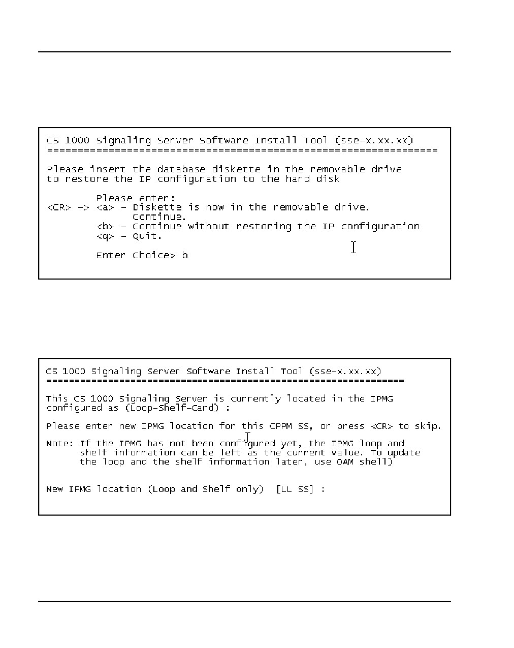
Press <CR> to continue with the configuration. The Restore IP
configuration screen appears (Figure 92).
Figure 92
Restore IP configuration
3
Enter b at the prompt to bypass the restore of IP configuration data. The
CP PM board location screen appears (Figure 93).
Figure 93
CP PM board location
NN43041-310
Standard 01.11
October 2008
Installing a Signaling Server
Page 219 of 466
4
Enter the location (loop and shelf) of the IPMG board.
Note: If the IPMG has not been configured yet, the loop and shelf
information can be left at the current value. The IPMG board location can
be updated using OAM shell commands after the Signaling Server is
configured.
5
The Leader/Follower configuration screen appears (Figure 94).
Figure 94
Leader/Follower Signaling Server configuration
CS 1000 Signaling Server Software Install Tool (sse-x.xx.xx)
=====================================================================
Note: This step will over-write all existing configuration parameters
on this Signaling Server.
Please select the role of this Signaling Server.
If this Signaling Server will be a Leader then its data networking
and IP Telephony parameters must be entered now. (This will pre-
configure the IP Telephony node files.)
If this Signaling Server will be a Follower then its data networking
and IP Telephony parameters must be configured through Element
Manager later.
Please enter:
<CR> -> <a> - Set this Signaling Server as a Leader.
<b> - Set this Signaling Server as a Follower.
<q> - Quit.
Enter Choice>
6
Configure the Signaling Server as a Leader or Follower. If there is already
a Leader Signaling Server in the IP Telephony node, enter b at the prompt
to configure this Signaling Server as Follower. The Follower Signaling
Server configuration screen appears (Figure 95). Go to step 15 on
page 211.
Communication Server 1000E Installation and Commissioning
Page 220 of 466
Installing a Signaling Server
Figure 95
Follower Signaling Server configuration
CS 1000 Signaling Server Software Install Tool (sse-x.xx.xx)
=======================================================================
This Follower Signaling Server will obtain its data network and IP
telephony configuration from the Leader Signaling Server at boot.
To identify this Signaling Server, please enter a Hostname.
Hostname : SS_Node276_Ldr
7
If there is not a Leader Signaling Server in the IP Telephony node already,
or if the Signaling Server is to be a stand-alone Signaling Server, press
<CR> or enter a at the prompt to configure this Signaling Server as
Leader.
NN43041-310
Standard 01.11
October 2008
Installing a Signaling Server
Page 221 of 466
8
Configure the application configuration for this Signaling Server. See
Figure 96.
•
If you are planning on enabling the IP Phone TPS, Virtual Trunk TPS,
and optional Network Routing Service (NRS) applications on this
Signaling Server, enter a at the prompt to configure this Signaling
Server as a co-resident Signaling Server.
•
If you are planning on enabling only the NRS on this Signaling
Server:
— If this Signaling Server is to be associated with a Call Server,
enter a at the prompt to configure this Signaling Server as a
co-resident Signaling Server. After you finished installing the
Signaling Server software, you can disable the IP Phone TPS
and Virtual Trunk TPS in Element Manager (refer to Element
Manager: System Administration (NN43001-332)).
— If this Signaling Server is not to be associated with a Call Server,
enter b at the prompt to set this Signaling Server as a
Standalone Signaling Server - NRS.
Figure 96
Application configuration
CS 1000 Signaling Server Software Install Tool (sse-x.xx.xx)
=====================================================================
Please select the application configuration for this Signaling Server.
Please enter:
<CR> -> <a> - Co-resident (LTPS + VTRK + NRS).
<b> - Stand-alone (NRS only - no Call Server).
<q> - Quit.
Enter Choice>
Depending on the application configuration selected, either the
NRS type: co-resident Signaling Server screen (Figure 97 on page 222)
or the NRS type: standalone Signaling Server screen (Figure 98 on
page 222) appears.
Communication Server 1000E Installation and Commissioning
Page 222 of 466
Installing a Signaling Server
Figure 97
Standalone Signaling Server - NRS
CS 1000 Signaling Server Software Install Tool (sse-x.xx.xx)
=====================================================================
Please select the Network Routing Service (NRS) configuration for this
Signaling Server.
Please enter:
<CR> -> <a> - H.323 Gatekeeper and SIP Redirect/Proxy Server.
<b> - H.323 Gatekeeper only.
<c> - SIP Redirect/Proxy Server only.
Enter Choice>
Figure 98
NRS type — co-resident Signaling Server
CS 1000 Signaling Server Software Install Tool (sse-x.xx.xx)
=====================================================================
Please select the type of Network Routing Service (NRS) for this
Signaling Server.
Please enter:
<CR> -> <a> - Primary.
<b> - Alternate.
<c> - Failsafe.
Enter Choice>
9
Select the type of NRS to be provided by this Signaling Server. See
Figure 98 for a co-resident Signaling Server. See Figure 97 for a
stand-alone Signaling Server.
•
If this Signaling Server is to be the Primary NRS, enter a.
•
If this Signaling Server is to be the Alternate NRS, enter b.
•
If this Signaling Server is not a stand-alone Signaling Server and is
to be the Fail-safe NRS, enter c.
Refer to IP Peer Networking: Installation and Commissioning (NN43001-313)
for more information on the NRS.
NN43041-310
Standard 01.11
October 2008
Installing a Signaling Server
Page 223 of 466
Depending on whether the Signaling Server is configured as Leader,
Follower or Stand-alone, the Leader Signaling Server configuration
screen (Figure 99), the Follower Signaling Server configuration screen
(Figure 100) or the Stand-alone Signaling Server configuration screen
(Figure 101) appears.
Figure 99
Leader Signaling Server configuration
CS 1000 Signaling Server Software Install Tool (sse-x.xx.xx)
=====================================================================
Please enter the data networking and IP Telephony parameters for
this Leader Signaling Server.
Node ID
: 276
Hostname
: SS_Node276_Ldr
ELAN IP
: 192.168.10.20
ELAN subnet mask: 255.255.255.0
ELAN gateway IP : 192.168.10.1
TLAN IP
: 192.168.20.20
TLAN subnet mask: 255.255.255.0
TLAN gateway IP : 192.168.20.1
Node IP
: 192.168.10.20
Call Server IP
: 192.168.10.10
Figure 100
Follower Signaling Server configuration
CS 1000 Signaling Server Software Install Tool (sse-x.xx.xx)
=======================================================================
This Follower Signaling Server will obtain its data network and IP
telephony configuration from the Leader Signaling Server at boot.
To identify this Signaling Server, please enter a Hostname.
Hostname : SS_Node276_Ldr
Communication Server 1000E Installation and Commissioning
Page 224 of 466
Installing a Signaling Server
Figure 101
Stand-alone Signaling Server configuration
CS 1000 Signaling Server Software Install Tool (sse-x.xx.xx)
=====================================================================
Please define the data networking parameters for this Standalone
Signaling Server. Note that the ELAN parameters are necessary for
management access (e.g. SNMP).
Hostname
: SS_SA
ELAN IP
: 192.168.10.20
ELAN subnet mask: 255.255.255.0
ELAN gateway IP : 192.168.10.1
TLAN IP
: 192.168.20.20
TLAN subnet mask: 255.255.255.0
TLAN gateway IP : 192.168.20.1
10
Enter the data networking and IP telephony parameters for the Signaling
Server, as prompted.
•
If this is a Leader Signaling Server, enter the parameters for the
Node, ELAN network interface, TLAN network interface, and Call
Server as required. See Figure 83 on page 209. For the Call Server:
— If installing the Signaling Server at an office that is not a branch
office, enter the ELAN network interface IP address of the Call
Server.
— If installing the Signaling Server at a branch office, enter the
ELAN network interface IP address of the MG 1000B Core.
•
If this is a Follower Signaling Server, enter the Hostname of the
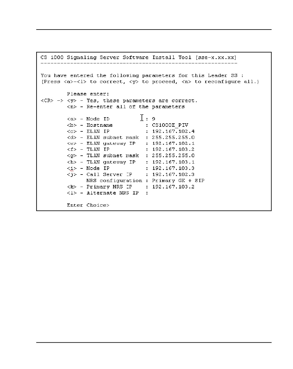
Leader Signaling Server. The IP telephony parameter configuration
screen appears (Figure 102 on page 225).
NN43041-310
Standard 01.11
October 2008
Installing a Signaling Server
Page 225 of 466
Figure 102
IP Telephony parameter configuration
•
Proceed to step 16 on page 213.
•
If this is a stand-alone Signaling Server and not associated with a
Call Server (that is, b was selected in step 11 on page 206), enter the
TLAN subnet parameters as required. The Call Server IP address is
automatically set to 0.0.0.0.
The IP information applies to a temporary IP Telephony node. This
ensures that the existing node is not impacted. This also preconfigures
the IP Telephony node files. In Signaling Server: Installation and
Commissioning (NN43001-312), the node files are imported to Element
Manager for further configuration.
Communication Server 1000E Installation and Commissioning
Page 226 of 466
Installing a Signaling Server
Depending on whether the Signaling Server is configured as Primary,
Alternate or Stand-alone, the Primary NRS IP address screen (Figure
103), the Alternate NRS IP address screen (Figure 104), or both in
succession (for a Stand-alone Signaling Server) appear.
Figure 103
Primary NRS IP address
CS 1000 Signaling Server Software Install Tool (sse-x.xx.xx)
=====================================================================
Please enter the Primary NRS IP Address:
Primary NRS IP
:
Figure 104
Alternate NRS IP address
CS 1000 Signaling Server Software Install Tool (sse-x.xx.xx)
=====================================================================
Please enter the Alternate NRS IP Address:
Alternate NRS IP :
11
Enter the Primary NRS IP address or the Alternate NRS IP address,
depending on the option entered in step 12 on page 207 or step 13 on
page 208.
•
If a was entered in step 13, you can enter the address of the Alternate
NRS if you know it, but it is not required. See Figure 86 on page 211.
•
If b was entered in step 13, enter the address of the Primary NRS.
See Figure 85 on page 211.
•
If c was entered in step 13:
— Enter the address of the Primary NRS. See Figure 85.
— Enter the address of the Alternate NRS. See Figure 86.
•
If d was entered in step 12:
— Enter the address of the Primary NRS (optional).
NN43041-310
Standard 01.11
October 2008
Installing a Signaling Server
Page 227 of 466
— If you did enter the address of the Primary NRS, enter the
address of the Alternate NRS (also optional).
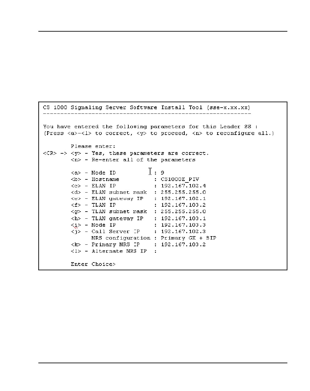
The Gatekeeper configuration can be updated later using Element
Manager. The IP telephony parameter configuration screen appears
(Figure 105).
Figure 105
IP Telephony parameter configuration
Communication Server 1000E Installation and Commissioning
Page 228 of 466
Installing a Signaling Server
12
Press <CR> or enter y to confirm all parameters entered, n to re-enter all
parameters, or a letter a through l to change the value of the
corresponding system parameter. The configuration screens for a
Follower and Standalone Signaling Server - NRS are similar, showing the
same list of parameters, specifically:
•
The screen for the Follower Signaling Server displays only the value
for the Hostname parameter; all other values are blank.
•
The screen for the stand-alone Signaling Server displays values for
the Hostname, ELAN network interface, TLAN network interface, and
NRS parameters. The Node ID field is set to 0. The Call Server IP
field is set to 0.0.0.0.
The following message is displayed:
For future reference, the ELAN MAC address is:
"00:02:b3:c5:5l:c6".
Note: The ELAN network interface MAC address must be configured in
the Element Manager node configuration web page.
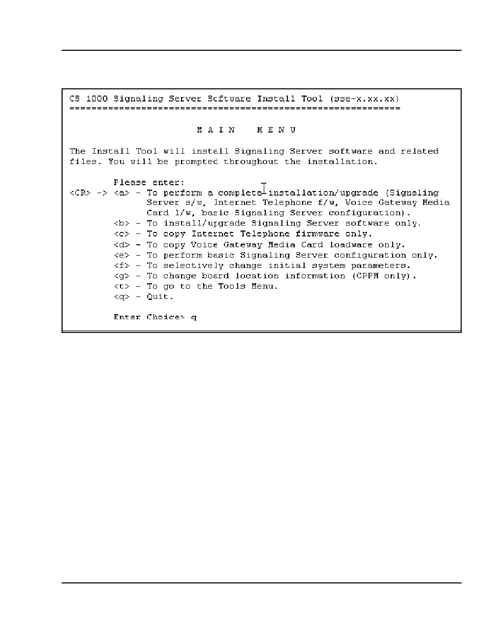
The Install Tool Main Menu screen appears (Figure 106):
NN43041-310
Standard 01.11
October 2008
Installing a Signaling Server
Page 229 of 466
Figure 106
Install tool
13
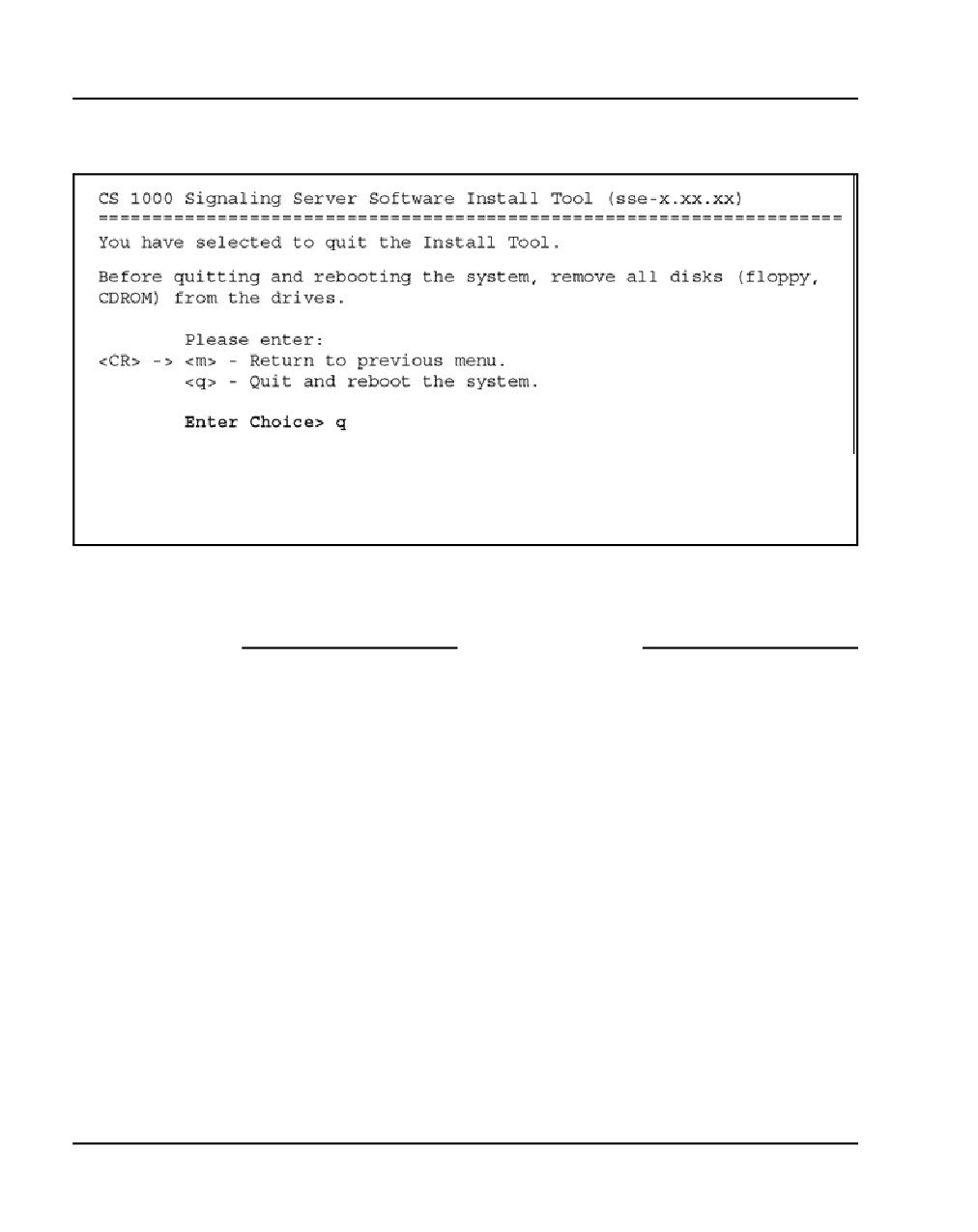
Enter q to quit the Install Tool. Confirm to reboot the system. The
Installation Tool quit confirmation screen appears (Figure 107).
Communication Server 1000E Installation and Commissioning
Page 230 of 466
Installing a Signaling Server
Figure 107
Installation Tool quit confirmation
14
Enter q to close/terminate the Installation Tool and reboot the Signaling
Server.
End of Procedure
Adding a follower Signaling Server
After configuration and reboot, a Follower Signaling Server sends out
BOOTP requests and waits for a response. Since the Follower Signaling
Server is not yet configured in an IP Telephony node, there is no BOOTP
response. Do not wait for this response. Complete Procedure 45, “Adding a
Follower Signaling Server to an IP Telephony node,” on page 231.
NN43041-310
Standard 01.11
October 2008
Installing a Signaling Server
Page 231 of 466
Procedure 45
Adding a Follower Signaling Server to an IP Telephony node
Note: The first time the Follower Signaling Server is installed, it cannot
obtain the system login and password, and does not have the current
CONFIG.INI file with the Call Server IP address, therefore the FTP fails.
In subsequent Follower installations, FTP succeeds.
1
Open the Web browser.
2
Enter the Signaling Server Node IP address in the Address Bar of the
browser window and press Enter on the keyboard.
Note: The ELAN network interface IP address can be required, instead
of the Node IP address, to access the Element Manager login Web page
in secure environments.
3
The Element Manager Login Web page opens.
a. Enter a valid User ID and Password combination.
— A valid User Id and Password combination is one that is defined
on the Call Server.
The IP Address of the Call Server appears in the Call Server IP
Address field.
b. Click Login.
The System Overview Web page appears.
4
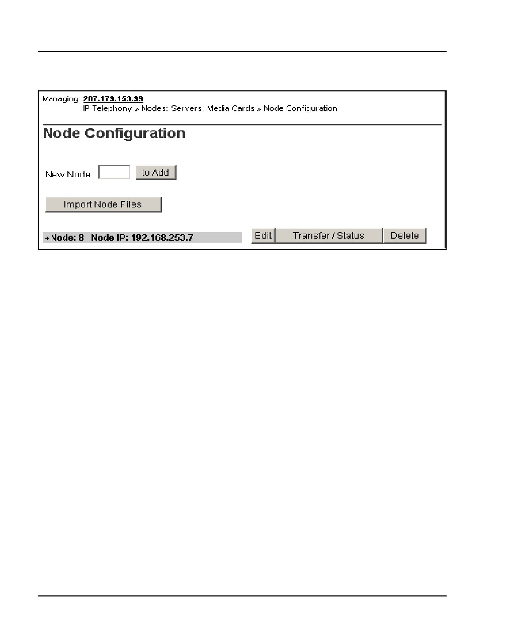
Select IP Network > Nodes: Servers, Media Cards from the navigator.
The Node Configuration web page opens, as shown in Figure 108.
Communication Server 1000E Installation and Commissioning
Page 232 of 466
Installing a Signaling Server
Figure 108
Node Configuration web page
5
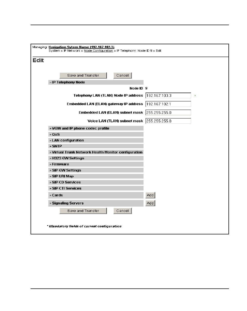
Click Edit next to the node to which the Follower Signaling Server is to be
added. The Edit web page opens, as shown in Figure 109.
NN43041-310
Standard 01.11
October 2008
Installing a Signaling Server
Page 233 of 466
Figure 109
Edit web page
6
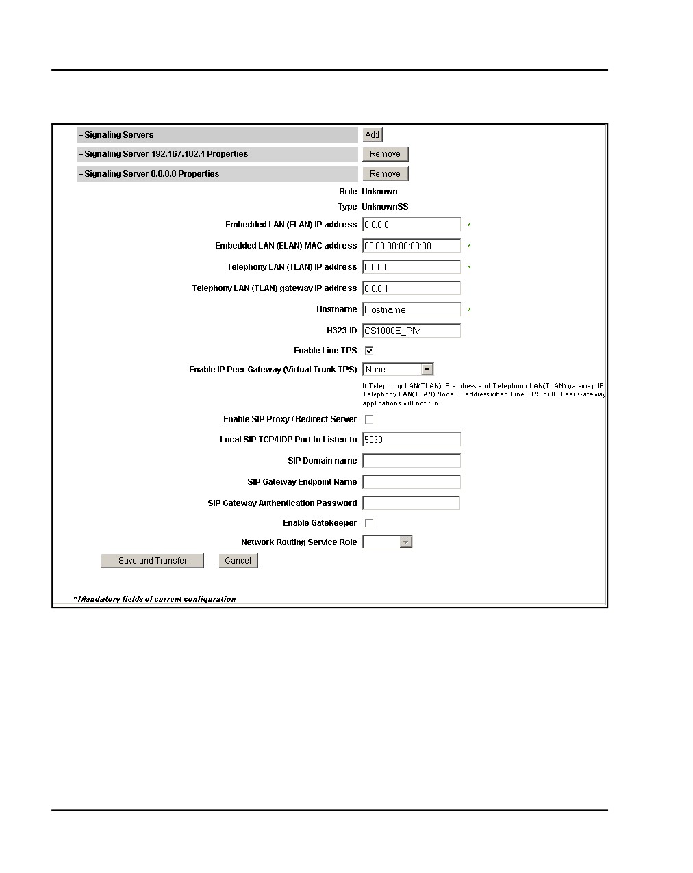
Click Add next to Signaling Servers.The section expands to show a list of
Signaling Servers and a blank template for entering Signaling Server
xxx.xxx.xxx.xxx properties, as shown in Figure 110.
Communication Server 1000E Installation and Commissioning
Page 234 of 466
Installing a Signaling Server
Figure 110
Signaling Server properties template
7
Enter the information corresponding to the Follower Signaling Server. The
Role field will automatically revert to Follower once the Follower Signaling
Server has been added.
NN43041-310
Standard 01.11
October 2008
Installing a Signaling Server
Page 235 of 466
8
Click Save and Transfer to transfer the updated IP Telephony node
information to the other elements of the node. Refer to Transferring IP
Telephony files, and IP Line: Description, Installation, and Operation
(NN43001-500) for detailed instructions on transferring IP Telephony
node information.
End of Procedure
Unpacking Help files for Virtual Terminal Emulator
Help files for the Virtual Terminal Emulator (VTE) component of Element
Manager are copied to the Signaling Server as compressed files during
installation of the Signaling Server software.
Unpacking the Help files is optional. However, they can be unpacked at any
time after the Signaling Server software is installed. To unpack the files, refer
to Signaling Server: Installation and Commissioning (NN43001-312).
IMPORTANT!
Unpacking the Help files takes approximately 20 to 30 minutes. Nortel
recommends that you unpack the files during a service outage.
Refer to Element Manager: System Administration (NN43001-632) for more
information on Element Manager and the Virtual Terminal Emulator.
Logging in to the Signaling Server
Use Procedure 46 on page 236 to log in to the vxWorksTM shell to access the
Signaling Server from a maintenance terminal.
Communication Server 1000E Installation and Commissioning
Page 236 of 466
Installing a Signaling Server
Procedure 46
Logging in to the Signaling Server
Before you begin, make sure the DTE-DTE null modem cable (supplied with
the Signaling Server) runs between the serial port on the back of the Signaling
Server and the maintenance terminal.
1
Make sure the Signaling Server is powered up and connected to the
maintenance terminal. Refer to Signaling Server: Installation and
Commissioning (NN43001-312).
The Signaling Server must boot successfully before the user can log in.
2
Press <CR> to invoke the login prompt.
3
Enter the login credentials by doing one of the following:.
•
If the Signaling Server has connected to the Call Server (the startup
messages indicate if the PBX link is up), use the PWD1 login to
access the Signaling Server.
•
If the Signaling Server is not connected to the Call Server:
a. Enter the default Signaling Server Command Line Interface
(CLI) login admin.
b. Enter the Signaling Server Command Line Interface (CLI)
password.
•
If this Signaling Server has just been installed and you are
logging in for the first time, enter the default password
cseadmin.
The system immediately prompts you to change the default
password.
•
If this is not the first login to the Signaling Server, enter the
appropriate password.
If you have forgotten the password, reset it from the Tools
Menu (see Signaling Server: Installation and
Commissioning (NN43001-312)).
End of Procedure
To log out of the Signaling Server, enter exit at the command line.
NN43041-310
Standard 01.11
October 2008
Installing a Signaling Server
Page 237 of 466
Verifying a successful configuration
To ensure that the Signaling Server Ethernet connections (for the ELAN and
TLAN subnets) are configured correctly, perform a ping test to one or more
of the other devices connected to the network, particularly the Call Server.
Procedure 47
Verifying the Signaling Server Ethernet connection
1
Log in to the Signaling Server, using Procedure 46 on page 236.
2
Ping the IP address of the Signaling Server. Enter the command:
ping x.x.x.x
Where x.x.x.x is the Signaling Server ELAN network interface IP
address.
3
Ping the IP address of the Call Server. Enter the command:
ping x.x.x.x,3
Where x.x.x.x is the Call Server ELAN network interface IP address.
4
If desired, repeat step 3 for other devices connected to the network.
End of Procedure
Testing the Leader Signaling Server
Configure two IP Phones to register to the Signaling Server on its temporary
node. These IP Phones must be provisioned on the Call Server. Refer to
Communication Server 1000E: Installation and Commissioning
(NN43041-310), Communication Server 1000M and Meridian 1:
Large System Installation and Commissioning (NN43021-310), or
Communication Server 1000M and Meridian 1: Small System Installation
and Configuration (NN43011-310) for the procedure appropriate to the
system. After provisioning, the telephones can call each other.
Communication Server 1000E Installation and Commissioning
Page 238 of 466
Installing a Signaling Server
NN43041-310
Standard 01.11
October 2008
250
Page 239 of 466
Configuring the IPMG
Contents
This section contains information on the following topics:
Configuring the IPMG in Element Manager
239
Configuring conference TDS
243
Configuring DSP Daughterboard Voice gateway channels
248
Configuring the IPMG in Element Manager
Procedure 48 on page 240 describes how to configure the IPMG in Element
Manager (for instructions on logging in to Element Manager, refer to steps 1 -
3 in Procedure 35 on page 166).
Communication Server 1000E Installation and Commissioning
Page 240 of 466
Configuring the IPMG
Procedure 48
Configuring the IPMG (Element Manager)
1
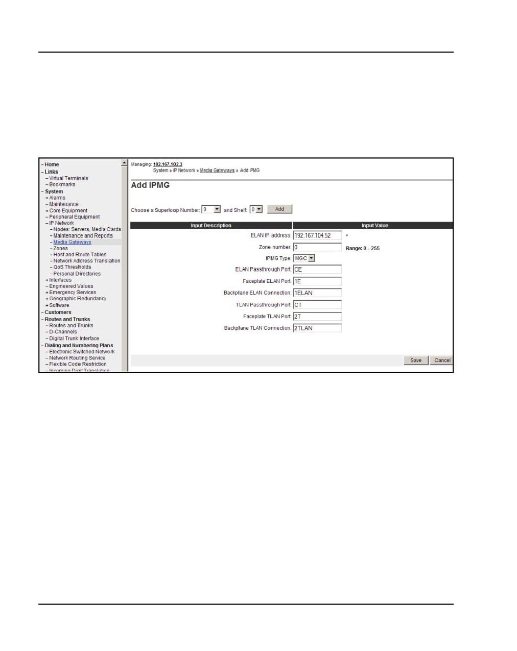
In Element Manager, select IP Network > Media Gateways. Select the
appropriate Superloop Number and Shelf. Click Add.
Figure 111
Add IPMG
2
The preceding screen appears (see Figure 111). Enter the IP address,
zone number, and the Media Gateway type (in this case, a Media
Gateway Controller). Selecting “MGC” automatically fills in the remaining
fields (“CE”, “E1”, “E”, “CT”, “T2”, and “T”). Click Submit.
Note: The IP address entered here is the same IP address as the one
configured on the MGC in an earlier procedure.
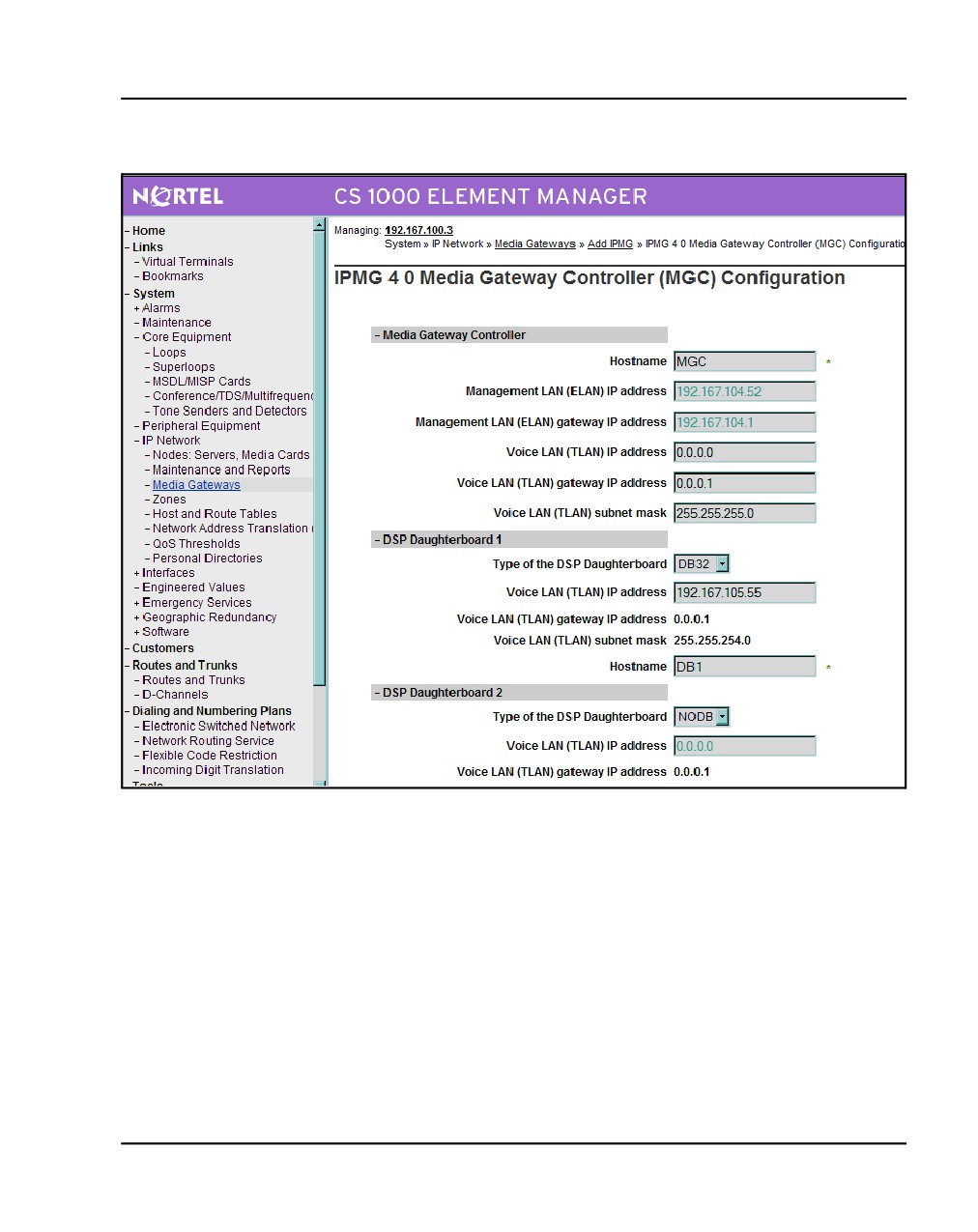
The following screen appears (Figure 112 on page 241):
3
Enter the Gateway IP addresses and Voice LAN IP addresses. If the MGC
has DSP daughterboards connected, select the type and enter the IP
addresses.
NN43041-310
Standard 01.11
October 2008
Configuring the IPMG Page 241 of 466
Figure 112
IPMG MGC configuration
4
Once configuration of the MGC is complete, click Add. The following
screen appears (see Figure 113 on page 242):
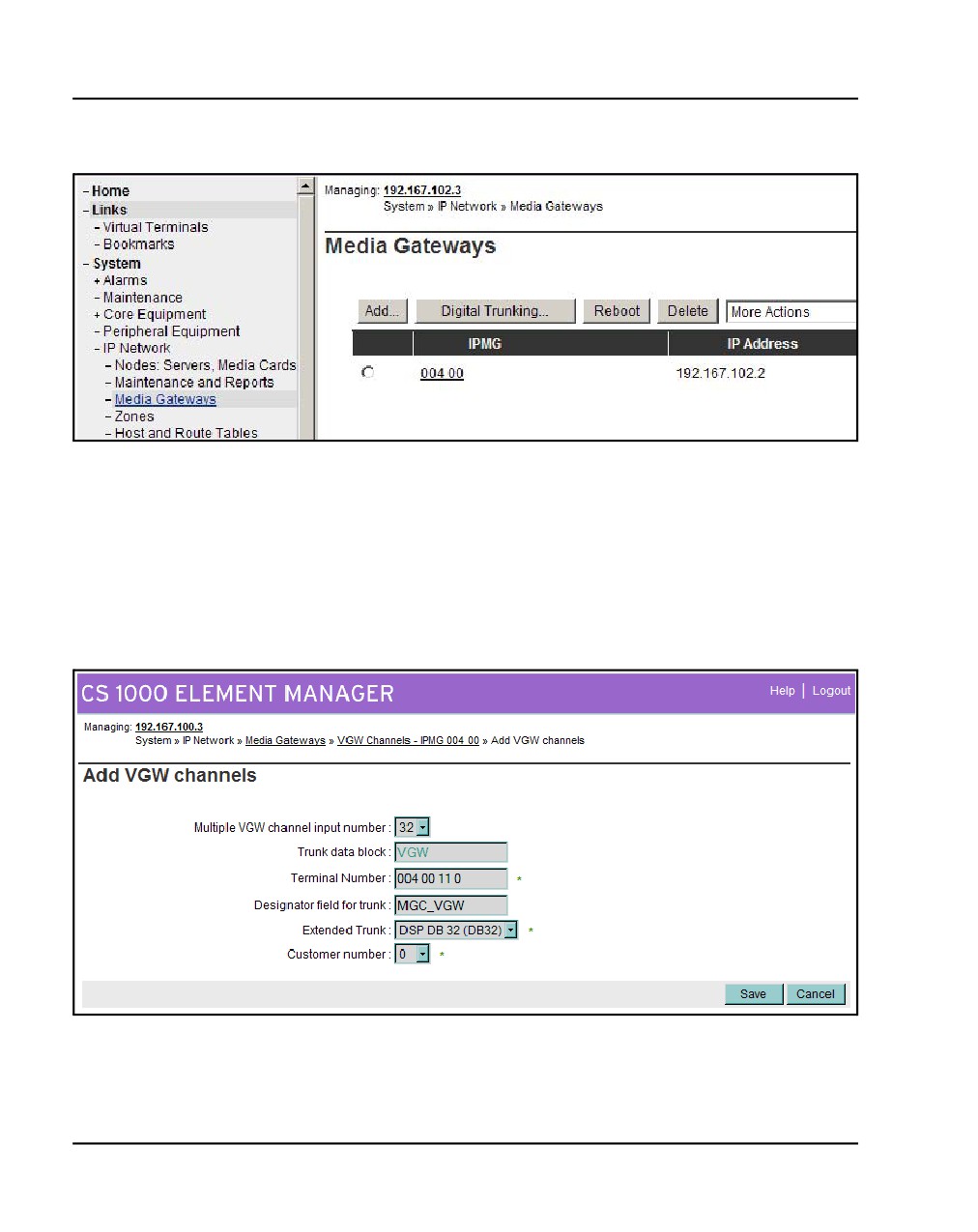
5
The Media Gateways screen lists the superloop and shelf numbers, IP
address, zone, and type of the recently configured MGC. Click the
radio-button next to the superloop. From the drop-down list select Add
VGW channels.
Communication Server 1000E Installation and Commissioning
Page 242 of 466
Configuring the IPMG
Figure 113
Media Gateways
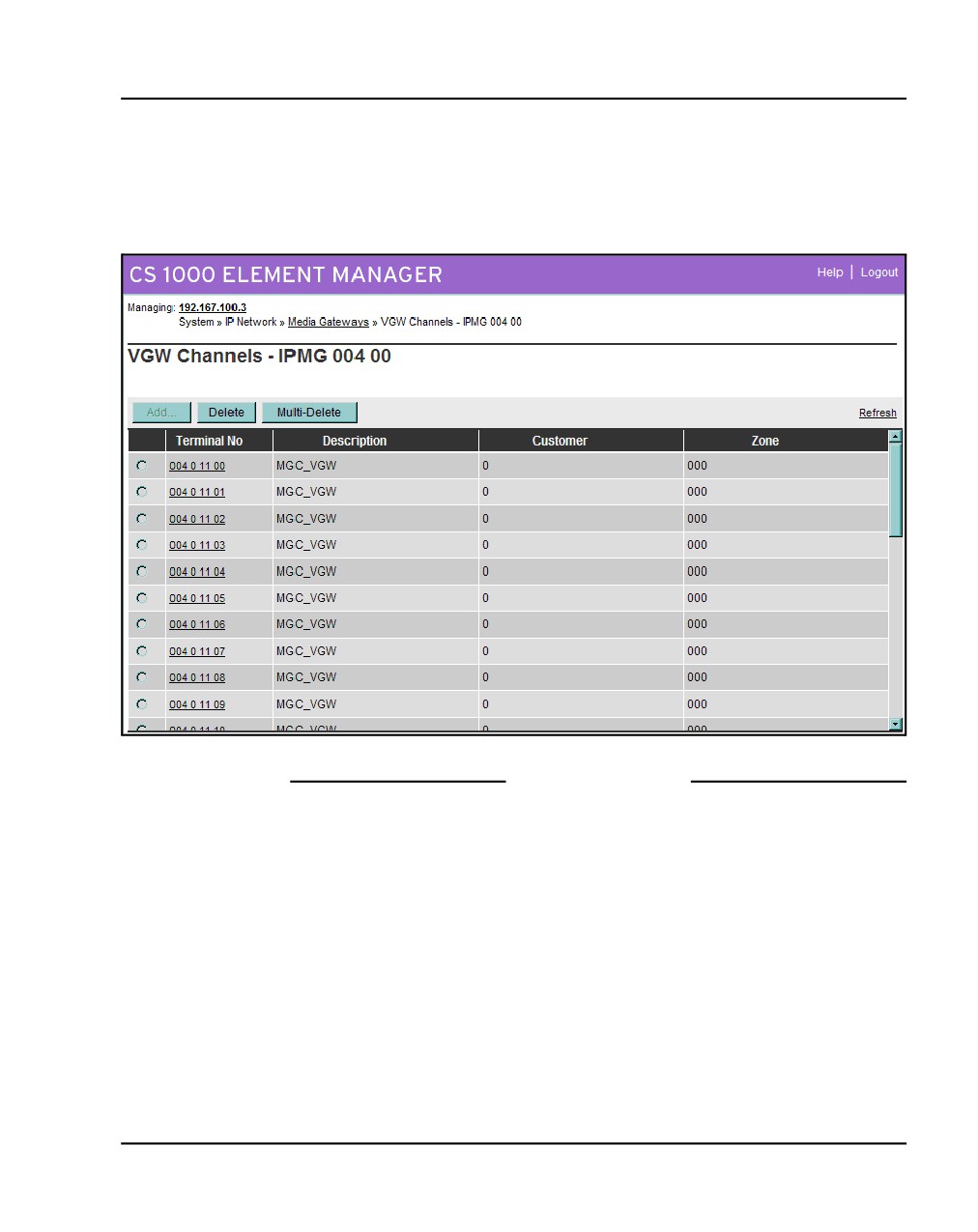
The following screen appears (see Figure 114):
6
In this screen, select the number of required channels, the Terminal
Number (the superloop and shelf numbers of the MGC, the card number,
and the unit). Provide a name and the daughterboard and customer type.
Click Save.
Figure 114
Add VGW channels
NN43041-310
Standard 01.11
October 2008
Configuring the IPMG Page 243 of 466
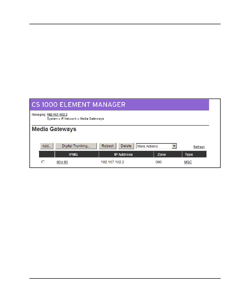
The following screen appears (Figure 115):
The MGC has been added to the list.
Figure 115
VGW Channels - IPMG
End of Procedure
Configuring conference TDS
Procedure 49 on page 244 describes how to configure conference TDS for an
IPMG using the CLI. To configure conference TDS for IPMG using Element
Manager see Procedure 50 on page 245.
Communication Server 1000E Installation and Commissioning
Page 244 of 466
Configuring the IPMG
Procedure 49
Configure conference TDS (CLI)
1
Enter LD 17.
>LD 17
CFN000
MEM AVAIL: (U/P): 99278047
USED U P: 4965412 26361
TOT: 104269820
DISK SPACE NEEDED: 20 KBYTES
DCH
AVAIL:
255
USED:
0
TOT:
255
AML
AVAIL:
16
USED:
0
TOT:
16
REQ chg
TYPE cequ7
MPED
TERM
REMO
TERD
REMD
TERQ
REMQ
DDCS
DTCS
XCT
MGTDS 126
IPMG x x
MGTDS
MGCONF 127
IPMG 0 0
MGCONF
MFSD
DTDT
DLOP
PRI2
APVL
DTI2
EXT0
EXT1
SYNM
MEM AVAIL: (U/P): 99277361
USED U P: 4966043 26416
TOT: 104269820
DISK SPACE NEEDED: 20 KBYTES
End of Procedure
NN43041-310
Standard 01.11
October 2008
Configuring the IPMG Page 245 of 466
Procedure 50 describes how to configure conference TDS for IPMG using
Element Manager.
Procedure 50
Configuring conference TDS (Element Manager)
1
In the Element Manager screen, select IP Network > Nodes: Media
Gateways. The Media Gateway Configuration page appears.
2
Select the IPMG superloop (see Figure 116). Click the Loops button.
Figure 116
Media Gateway configuration
The loop configuration page appears.
3
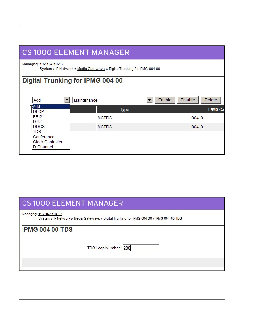
From the drop down menu (see Figure 117 on page 246), select TDS to
add a TDS loop.
Communication Server 1000E Installation and Commissioning
Page 246 of 466
Configuring the IPMG
Figure 117
Loop configuration
The TDS loop configuration page appears (see Figure 118).
4
Enter the TDS loop number (0 - 255).
Figure 118
TDS Loop configuration
NN43041-310
Standard 01.11
October 2008
Configuring the IPMG Page 247 of 466
5
Click Save. It does not become available until a loop number has been
entered and TAB has been used to move the cursor.
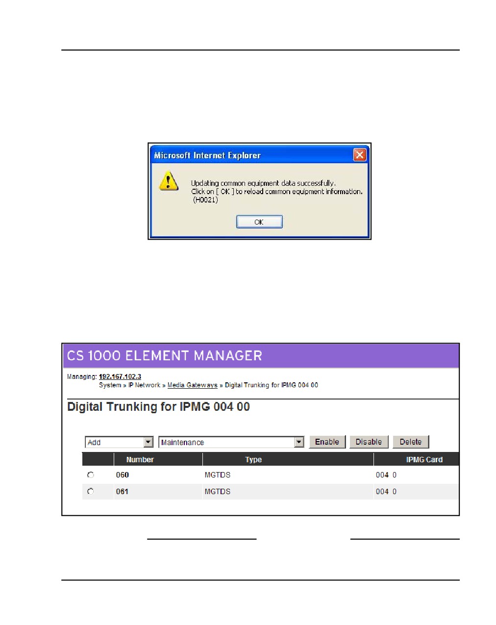
The following message box appears:
Figure 119
Confirmation
6
Click OK to complete the configuration.
The updated loop configuration page appears (see Figure 120). The new
Conference loop is displayed.
Figure 120
Loop configuration (updated)
End of Procedure
Communication Server 1000E Installation and Commissioning
Page 248 of 466
Configuring the IPMG
Configuring DSP Daughterboard Voice gateway channels
Procedure 51 describes how to configure DSP Daughterboard Voice gateway
channels using the CLI. To configure DSP Daughterboard Voice gateway
channels using Element Manager see Procedure 50 on page 245.
Procedure 51
Configure DSP Daughterboard Voice gateway channels (CLI)
1
Enter LD 14
>LD 14
REQ new 32
TYPE vgw
TN
4 0 0 0
DES db32
XTRK db32
CUST 0
NEW TRK
TN
004 0 00 00
RT
0
MB
0
MEM AVAIL: (U/P): 15721651
USED U P: 6241131 26590
TOT: 21989372
DISK SPACE NEEDED: 24 KBYTES
2MB BACKUP DISKETTE(S) NEEDED: 1
(PROJECTED LD43 - BKO)
TNS
AVAIL: 32751
USED:
16
TOT: 32767
>LD 20
REQ: prt
TYPE: vgw
TN
<enter>
CDEN <enter>
CUST <enter>
XTRK <enter>
DATE <enter>
PAGE <enter>
DES DB32
TN
004 0 00 00 VIRTUAL
TYPE VGW
CUST 0
XTRK DB32
NN43041-310
Standard 01.11
October 2008
Configuring the IPMG Page 249 of 466
ZONE 004
End of Procedure
Communication Server 1000E Installation and Commissioning
Page 250 of 466
Configuring the IPMG
NN43041-310
Standard 01.11
October 2008
264
Page 251 of 466
Connecting an IR-8020M-101
Terminal Server
Contents
This section contains information on the following topics:
Introduction
251
Configuring a Terminal Server
253
Telnet Terminal Server virtual management port
256
Telnet CS 1000E COM port from a PC
257
Configuring a transparent rlogin port
258
Accessing an MRV Console Port through the on-board modem
262
CS 1000E COM port types
263
Introduction
Many third-party applications require serial port interfaces to provide a
connection to a PBX. As well, support staff traditionally use serial ports to
connect maintenance terminals and modems to a system for maintenance. As
the CS 1000E Call Server provides only two local serial ports for these
purposes, an IP-based Terminal Server is required to provide the necessary
standard serial ports for applications.
The CS 1000E system currently supports 2 terminal servers, the
IR-8020M-101 (non-ROHS) and the MRV LX8020S-102AC-R (ROHS).
This chapter contains information on connecting the IR-8020M-101. For
Communication Server 1000E Installation and Commissioning
Page 252 of 466
Connecting an IR-8020M-101 Terminal Server
information on connecting the MRV LX8020S-102AC-R, see “Connecting
an MRV LX8020S-102AC-R Terminal Server” on page 265.
As the Terminal Server is configured to automatically log in to the active Call
Server upon start-up, only one Terminal Server is required for the system. It
can be located anywhere on the LAN. One connection from each Call Server
COM1 port is connected to the Terminal Server.
Up to 16 TTY ports can be configured with the CS 1000E Call Server. The
Terminal Server can be used as a central point to manage several devices
through their serial ports.
The MRV IR-8020M-101 Terminal Server is used with the CS 1000E system
to provide serial connections for accessing the CS 1000E COM ports. The
user can access each COM port from a local PC through telnet sessions or
from a remote PC by dialing the on-board modem.
The Terminal Server provides IP connections to each Pseudo TTY (PTY)
ports 0-15 for monitoring CDR and traffic reports.
The MRV IR-8020M-101 Terminal Server is supported by the CS 1000E
system. The IR-8020M-101 - In-Reach Standalone has 20 Console Ports and
a V.90 internal modem. A 19-inch rack-mount kit is provided with the unit.
On the MRV IR-8020M-101 Terminal Server, port 20 is the default
management port. It will be used for primary configuration of the IP address,
mask address and gateway address. Port 20 is reserved for configuring the
Terminal Server in a CS 1000E system. Port 1 to 19 can be configured for
Serial Data Interface for the CSE1000E system components.
IMPORTANT!
Before connecting the Terminal Server to another component of the
CS 1000E system, read and understand the documentation provided by
the Terminal Server’s manufacturer.
NN43041-310
Standard 01.11
October 2008
Connecting an IR-8020M-101 Terminal Server Page 253 of 466
This chapter contains the following procedures:
•
Procedure 52: "Connecting a Terminal Server to the system"
on page 254
•
Procedure 53: "Configure IP address for the Terminal Server"
on page 255
•
Procedure 54: "Run telnet from PC" on page 256
•
Procedure 55: "Accessing a CS 1000E from a PC through telnet
Terminal Server" on page 257
•
Procedure 56: "Configuring a transparent rlogin port" on page 258
•
Procedure 58: "Accessing an MRV Console Port through the
on-board modem" on page 262
Configuring a Terminal Server
Follow Procedure 52 to connect a Terminal Server with a CS 1000E system.
Table 16 lists the MRV cables required to install the IR-8020M-101 Terminal
Server in a CS 1000E system.
Table 16
Required MRV serial cables and connectors
Order Code
Description
NTDU6302
Connects MRV Terminal Server to any
standard DTE port or DCE port when a Null
modem is used
NTDU6303
Used for telnet, rlogin connections
P/N-151-3028
Male RJ-45 to Male RJ-45 with connectors,
10 feet
P/N-350-0308
Female RJ-45 to Female DB9
Communication Server 1000E Installation and Commissioning
Page 254 of 466
Connecting an IR-8020M-101 Terminal Server
Customer-made cables with the following pin out (as NTDU6302) can also
be used. See Table 17.
Table 17
Customer made cable pin out
Pins on DB9 Female
Pins on RJ45 Male (MRV Terminal Server)
1
DCD
2
DTR
6
DSR
2
RXD
3
TxD
3
TXD
6
RxD
4
DTR
7
DSR/DCD
5
S GND
4
TxD GND
5
RxD GND
7
RTS
1
CTS
8
CTS
8
RTS
9
N/C
Procedure 52
Connecting a Terminal Server to the system
1
Connect the MRV P/N-151-3028 serial cable from the Terminal Server
console port 20 to the PC COM port.
WARNING
Port 20 is the default console port. Do not change the
configuration for port 20.
2
Plug MRV PC Card (in MRV package) into Terminal Server faceplate
socket, and power on the Terminal Server.
3
Start the MRV HyperTerminal application. In Windows:
Start > Programs > Accessories > Communication >
HyperTerminal.exe
NN43041-310
Standard 01.11
October 2008
Connecting an IR-8020M-101 Terminal Server Page 255 of 466
4
Configure HyperTerminal to communicate with the Terminal Server’s
management port:
a. Set baud rate to 9600.
b. Set data bits to 8.
c. Set parity to none.
d. Set stop bit to 1.
e. Set flow control to “None”.
f.
Set Terminal Emulation to VT100.
g. Press <CR> until you receive a log-in prompt.
5
Log in to the Terminal Server. Enter:
ACCESS
6
Enter the user name. Enter:
ADMIN
7
Set privileged mode. Enter:
SET PRIV
8
Enter the password. Enter:
SYSTEM
End of Procedure
Configuring the Terminal Server IP address
Procedure 53
Configure IP address for the Terminal Server
Note: The IP address can be configured or changed only from local
management port 20.
1
Configure the Terminal Server’s IP address. At the In-Reach_Priv prompt.
Enter:
define server ip address [ip address]
2
Configure the Terminal Server’s IP subnet mask. Enter:
define server ip subnet mask [ip address]
Communication Server 1000E Installation and Commissioning
Page 256 of 466
Connecting an IR-8020M-101 Terminal Server
3
Configure the Terminal Server’s IP primary gateway address. Enter:
define server ip primary gateway address [ip address]
4
Check Terminal Server configuration. Enter:
list server ip
Example commands:
define server ip address 172.16.3.50
define server ip subnet mask 255.255.255.0
define server ip primary gateway address 172.16.3.1
End of Procedure
Telnet Terminal Server virtual management port
Connect the Terminal Server ethernet port to the ELAN using a CAT5
ethernet cable. The virtual management port 0 is accessible from an online PC
using a telnet session. The Terminal Server can now be configured from the
on-line PC.
Procedure 54
Run telnet from PC
1
Use Start > Run
Input telnet command: telnet ip-address port#
Where:
ip-address: Terminal Server IP address
Port#: The target port number on Terminal Server=2000+(xx x 100)
For Terminal Server virtual management port xx=0
Example: telnet 172.16.3.50 2000
2
Press <CR> until the MRV login prompt appears.
3
Input login password and username to log in to the virtual management
port. The default password is "access".
End of Procedure
NN43041-310
Standard 01.11
October 2008
Connecting an IR-8020M-101 Terminal Server Page 257 of 466
Telnet CS 1000E COM port from a PC
Connect port xx (xx = 1 - 19) of the Terminal Server to COM1 port of the
CS 1000E Call Server.
Follow Procedure 55 to establish access to a Call Server from a PC through
telnet Terminal Server. Use the same port number for each procedure step.
Procedure 55
Accessing a CS 1000E from a PC through telnet Terminal Server
1
Disable IP TCP Keepalive Timer so that the telnet session is always on
and LAN traffic is reduced. Enter:
DEFINE PORT xx IP TCP KEEPALIVE TIMER 0
Where: xx = 1-19
Note: Do not change the configuration for the default console (port 20).
2
Specify the character to be transferred for <CR> in telnet. Enter:
define port xx TELNET NEWLINE FILTERING CR
3
Define the port baud rate to equal the baud rate of the CS 1000E COM
port. Enter:
define port xx speed [BAUDRATE]
Where: xx = Port number from 1-19 and BAUDRATE = the baud rate of
the connected Call Server COM port.
4
Logout. Enter:
logout port xx
5
Check the configuration. Enter:
list port xx alternate chara
list port xx telnet chara
6
Run telnet on the PC.
a. In Windows:
Start > Run
Communication Server 1000E Installation and Commissioning
Page 258 of 466
Connecting an IR-8020M-101 Terminal Server
b. Enter the Input telnet command. Enter the command:
TELNET xxx.xx.x.xx xxxx
Where:
xxx.xx.x.xx = Terminal Server IP Address
xxxx = telnet port (for port 1 to 19)
Note: The value of the target telnet port, xxxx, is determined using the
following formula:
TELNET PORT = 2 000 + (port number × 100)
For example, if the telnet port is 7, then:
TELNET PORT = 2 000 + (port number x 100)
= 2 000 + (700)
= = 2700
If the Terminal Server IP Address is 172.16.3.50 and the telnet port is 7,
then TELNET command line is:
TELNET 172.16.3.50 2700
Example:
telnet 172.16.3.50 2000 (telnet to virtual management port)
telnet 172.16.3.50 2700 (telnet port 7)
End of Procedure
Configuring a transparent rlogin port
The CS 1000E system uses Pseudo TTY (PTY) ports as TTY ports. All serial
applications, such as CDR and Traffic, can be implemented through PTY
ports. PTY ports are configured in LD 17. An external device, such as a
printer, can access a Call Server PTY port through the Terminal Server by
using a remote login (rlogin) session. Using HyperTerminal, follow
Procedure 56 to configure a transparent rlogin port.
Procedure 56
Configuring a transparent rlogin port
1
Enable keepalive timer 1 for the port. Enter the command:
DEFINE PORT XX IP TCP KEEPALIVE TIMER 1
NN43041-310
Standard 01.11
October 2008
Connecting an IR-8020M-101 Terminal Server Page 259 of 466
Where:
xx = port number
2
Enable a dedicated service using rlogin. Enter the command:
DEFINE PORT XX RLOGIN DEDICATED SERVICE xx.xx.xx.xx
Where:
xx = port number
xx.xx.xx.xx = port IP address
3
Enable the port to be accessible only by local command and from a serial
connection only. Enter the command:
DEFINE PORT xx ACCESS LOCAL
Where:
xx = port number
4
Enable the In-Reach Element Manager to complete a ZMODEM transfer
using the rlogin feature. Enter the command:
DEFINE PORT xx RLOGIN TRANSPARENT MODE ENABLED
Where:
xx = port number
Note 1: When the rlogin transparent mode is enabled, characters are
passed raw (without interpretation) and transparently within an rlogin
session. This allows the ZMODEM transfer to complete. See Table 18 for
ZMODEM requirements.
Table 18
ZMODEM requirements
Feature
Setting
Typeahead
1024
TCP window size
1024
telnet CSI ES
Enabled
telnet NEW LINE FILTER
LF or Standard
Communication Server 1000E Installation and Commissioning
Page 260 of 466
Connecting an IR-8020M-101 Terminal Server
5
Enable autoconnect for the port. Enter the command:
DEFINE PORT xx AUTOCONNECT ENABLED
Where:
xx = port number
6
Enable autodedicate for the port. Enter the command:
DEFINE PORT xx AUTODEDICATED ENABLED
Where:
xx = port number
7
Define a user name for the port. Enter the command:
DEFINE PORT xx USERNAME “ptyxx”
Where:
xx = port number
ptyxx = User Name is the pty port set during Call Server configuration
for rlogin connection. The pty port is set using LD 17. For example, in LD
17, configure TTY 2 as pty. The port # username on Terminal Server
becomes "pty2", not "PTY2" or "pty02".
Note 1: Ignore the following MRV information message during using
DEFINE command. "In-Reach -729- Parameter cannot be modified by a
set command". This is informational only that you must use DEFINE and
not the more general SET command. It is not an error.
Note 2: The quotation marks (““) are also required around "PTYxx"
8
Log out of the port. Enter the command:
LOGOUT PORT xx
Where:
xx = port number
NN43041-310
Standard 01.11
October 2008
Connecting an IR-8020M-101 Terminal Server Page 261 of 466
9
Check port configuration. Enter the command:
LIST PORT xx
LIST PORT xx ALTERNATE CHARA
Where:
xx = port number
End of Procedure
Configuring a transparent rlogin port with sample data
Sample data has been incorporated into Procedure 57. This configuration
shows that a device connected to MRV Port 2 will rlogin 47.11.166.76
through pty 10.
Procedure 57
Configuring a transparent rlogin port
1
Enable keepalive timer 1 for the port. Enter the command:
DEFINE PORT 2 IP TCP KEEPALIVE TIMER 1
2
Enable a dedicated service using rlogin. Enter the command:
DEFINE PORT 2 RLOGIN DEDICATED SERVICE 47.11.166.76
3
Enable the port to be accessible only by local command and from a serial
connection only. Enter the command:
DEFINE PORT 2 ACCESS LOCAL
4
Enable the In-Reach Element Manager to complete a ZMODEM transfer
using the rlogin feature. Enter the command:
DEFINE PORT 2 RLOGIN TRANSPARENT MODE ENABLED
5
Enable autoconnect for the port. Enter the command:
DEFINE PORT 2 AUTOCONNECT ENABLED
6
Enable autodedicate for the port. Enter the command:
DEFINE PORT 2 AUTODEDICATED ENABLED
Communication Server 1000E Installation and Commissioning
Page 262 of 466
Connecting an IR-8020M-101 Terminal Server
7
Define a user name for the port. Enter the command:
DEFINE PORT 2 USERNAME “pty7”
Note: When typing the letters “pty”, they must be lower case letters. The
number must equal the pty number configured on the system.
8
Log out of the port. Enter the command:
LOGOUT PORT 2
End of Procedure
Accessing an MRV Console Port through the
on-board modem
The MRV IR-8020M Terminal Server is equipped with a V.90/K56flex 56
Kbps on-board modem. The modem port is 23. Follow Procedure 58 to access
an MRV Console Port through the on-board modem.
Procedure 58
Accessing an MRV Console Port through the on-board modem
1
Connect an analog telephone line to the MRV telephone line port.
2
Set up the remote PC connection.
3
Dial in to the MRV onboard modem from the PC.
4
From the PC, run HyperTerminal. Enter the command:
ATD [phone number]
Screen response:
CONNECT 9600/ARQ/V34/LAPM/V42BIS
Login
5
Log in to the In-Reach Element Manager using the default password, (see
steps 4,5,6,and 7 in Procedure 52 on page 254).
End of Procedure
Once logged in to the on-board modem, it is possible to telnet to ports 1-20.
It is also possible to rlogin to different IPs.
NN43041-310
Standard 01.11
October 2008
Connecting an IR-8020M-101 Terminal Server Page 263 of 466
CS 1000E COM port types
Table 19 lists various components of the CS 1000E system and their COM
port types.
Table 19
System components and COM port type
System component
COM port type
Baystack 460
9-pin DCE (male)
Baystack 470
9-pin DCE (male)
NTDU27 Signaling Server
9-pin DTE (male)
Note: Signaling Server comes
with a six-foot female-to-female
null modem cable.
NT4N64AA CPPII
9-pin DTE (male)
A0852632 Media Card L-adapter
9-pin DCE (female)
A0870611 MIRAN L-adapter
9-pin DCE (female)
P0609204 Media Card L-adapter
9-pin DTE (male)
P0609205 MIRAN L-adapter
9-pin DTE (male)
NTDU14 Gateway
9-pin DTE (male) (modified to
isolate pins 6, 7, and 8)
Use PORT 0 of NTBK48AA
3-port SDI cable.
Communication Server 1000E Installation and Commissioning
Page 264 of 466
Connecting an IR-8020M-101 Terminal Server
NN43041-310
Standard 01.11
October 2008
278
Page 265 of 466
Connecting an MRV LX8020S-102AC-R
Terminal Server
Contents
This section contains information on the following topics:
Introduction
265
Configuring a Terminal Server
268
Telnet Terminal Server virtual management port
271
Telnet to CS 1000E COM port from a PC
271
Configuring an rlogin port for various applications
273
Accessing an MRV Console Port through the on-board modem
276
CS 1000E COM port types
277
Introduction
Many third-party applications require serial port interfaces to provide a
connection to a PBX. As well, support staff traditionally use serial ports to
connect maintenance terminals and modems to a system for maintenance. As
the CS 1000E Call Server provides only two local serial ports for these
purposes, an IP-based Terminal Server is required to provide the necessary
standard serial ports for applications.
The CS 1000E system currently supports two Terminal Servers, the
MRV LX8020S-102AC-R (ROHS) and the IR-8020M-101 (non-ROHS).
This chapter contains information on connecting the LX8020S-102AC-R.
Communication Server 1000E Installation and Commissioning
Page 266 of 466
Connecting an MRV LX8020S-102AC-R Terminal Server
For information on connecting the IR-8020M-101, see “Connecting an
IR-8020M-101 Terminal Server” on page 251.
Differences between the two Terminal Servers include:
•
The IR-8020M-101 Management port is port 20. The
LX8020S-102AC-R contains a Diag Port at the front.
•
The IR-8020M-101 contains an external PC card slot; the
LX8020S-102AC-R does not.
•
Commands, command modes and command line interfaces are different
•
Default passwords are different for both
The Terminal Servers can be located anywhere on the LAN. One connection
from each Call Server COM1 port is connected to the Terminal Server.
Up to 16 TTY ports can be configured with the CS 1000E Call Server. The
Terminal Servers can be used as a central point to manage several devices
through their serial ports.
Both Terminal Servers are used with the CS 1000E system to provide serial
connections for accessing the CS 1000E COM ports. The user can access each
COM port from a local PC through telnet sessions or from a remote PC by
dialing the on-board modem.
The Terminal Servers provide IP connections to each Pseudo TTY (PTY)
ports 0-15 for monitoring CDR and traffic reports.
The LX8020S-102AC-R - LX Series Standalone has 20 Console Ports and a
V.90 internal modem. A 19-inch rack-mount kit is provided with the unit.
The DIAG port at the front end of the MRV LX8020S-102AC-R is the default
management port. It will be used for primary configuration of the IP address,
NN43041-310
Standard 01.11
October 2008
Connecting an MRV LX8020S-102AC-R Terminal Server Page 267 of 466
mask address and gateway address. The 20 Ports at the rear can be configured
for Serial Data Interface for CS 1000E system components.
IMPORTANT!
Before connecting the Terminal Server to another component of the
CS 1000E system, read and understand the documentation provided by
the Terminal Server’s manufacturer including the Quick Start Guide for
MRV server, LX Series Configuration Guide and MRV LX Series
Commands Reference Guide.
This chapter contains the following procedures:
•
Procedure 59: "Connecting a Terminal Server to the system"
on page 269
•
Procedure 60: "Configure IP address for the Terminal Server"
on page 270
•
Procedure 61: "Running telnet from PC" on page 271
•
Procedure 62: "Accessing a CS 1000E from a PC through telnet
Terminal Server" on page 272
•
Procedure 63: "Configuring an rlogin port for various applications"
on page 273
•
Procedure 64: "Accessing an MRV Console Port through the
on-board modem" on page 276
Communication Server 1000E Installation and Commissioning
Page 268 of 466
Connecting an MRV LX8020S-102AC-R Terminal Server
Configuring a Terminal Server
Follow Procedure 59 to connect a Terminal Server with a CS 1000E system.
Table 20 lists the MRV cables required to install the LX8020S-102AC-R
Terminal Server in a CS 1000E system.
Table 20
Required MRV serial cables and connectors
Order Code
Description
NTDU6302
Connects MRV Terminal Server to any standard
DTE port or DCE port when a Null modem is
used
NTDU6303
Used for telnet, rlogin connections
P/N-151-3028
Male RJ-45 to Male RJ-45 with connectors,
10 feet
P/N-350-0308
Female RJ-45 to Female DB9
Customer-made cables with the following pin out can also be used. See Table
21.
Table 21
Customer made cable pin out (same as NTDU6302)
Pins on DB9 Female
Pins on RJ-45 Male (MRV Terminal Server)
1
DCD
2
DTR
6
DSR
2
RXD
3
TxD
3
TXD
6
RxD
4
DTR
7
DSR/DCD
5
S GND
4
TxD GND
5
RxD GND
7
RTS
1
CTS
NN43041-310
Standard 01.11
October 2008
Connecting an MRV LX8020S-102AC-R Terminal Server Page 269 of 466
Table 21
Customer made cable pin out (same as NTDU6302)
Pins on DB9 Female
Pins on RJ-45 Male (MRV Terminal Server)
8
CTS
8
RTS
9
N/C
Procedure 59
Connecting a Terminal Server to the system
1
Connect the above mentioned MRV serial cable from the Terminal Server
Diag port at the front of the Terminal Server to the PC COM port.
2
Start the MRV HyperTerminal application. In Windows:
Start > Programs > Accessories > Communication >
HyperTerminal.exe
3
Configure HyperTerminal to communicate with the Terminal Server’s
management port:
a. Set baud rate to 9600.
b. Set data bits to 8.
c. Set parity to none.
d. Set stop bit to 1.
e. Set flow control to “None”.
f.
Set Terminal Emulation to VT100.
g. Press <CR> until you receive a log-in prompt.
4
Log in to the Terminal Server. Enter:
Log in: InReach <Enter>
Password access
5
To log into Superuser mode:
InReach: 0 >enable <enter>
6
Enter the default password. Enter:
Communication Server 1000E Installation and Commissioning
Page 270 of 466
Connecting an MRV LX8020S-102AC-R Terminal Server
System
End of Procedure
Configuring the Terminal Server IP address
Procedure 60
Configure IP address for the Terminal Server
Note: The IP address can be configured or changed only from the local
Management/ DIAG port.
1
Configure the Terminal Server’s IP address:
InReach:0 >>config interface 1 address <ip address>
2
Configure the Terminal Server’s IP subnet mask:
InReach:0 >>config interface 1 mask <subnet mask>
3
Configure the Terminal Server’s IP primary gateway address:
InReach:0 >>config gateway <gateway ip address>
4
Save the configuration and check it:
InReach:0 >>save config flash
InReach:0 >>show system chara
InReach:0 >>show interface1 chara
Example commands:
InReach:0 >>config interface 1 address 47.11.244.101
InReach:0 >>config interface 1 mask 255.255.255.0
InReach:0 >>config gateway 47.11.244.101
End of Procedure
NN43041-310
Standard 01.11
October 2008
Connecting an MRV LX8020S-102AC-R Terminal Server Page 271 of 466
Telnet Terminal Server virtual management port
Connect the Terminal Server ethernet port to the ELAN subnet using a CAT5
ethernet cable. The virtual management port 0 is accessible from an online PC
using a telnet session. The Terminal Server can now be configured from the
on-line PC.
Procedure 61
Running telnet from PC
1
In Windows, input the Telnet command
>Start > Run
telnet IP address port#
Where:
IP address = Terminal Server IP address
Port# = port no. (calculation of port shown below in Procedure 63 on
page 273
Example: telnet 47.11.244.101 2100 (if it is port 1)
Note: No port is used for the virtual management port.
2
Press <CR> until the MRV login prompt appears.
3
Input login password and username to log in to the virtual management
port.
End of Procedure
Telnet to CS 1000E COM port from a PC
Connect port xx (xx = 1 - 20) of the Terminal Server to COM1 port of the
CS 1000E Call Server.
Communication Server 1000E Installation and Commissioning
Page 272 of 466
Connecting an MRV LX8020S-102AC-R Terminal Server
Follow Procedure 62 to establish access to a Call Server from a PC through
telnet Terminal Server. Use the same port number for each procedure step.
Procedure 62
Accessing a CS 1000E from a PC through telnet Terminal Server
1
Connect to the management port or virtual management port as shown in
Procedure 61 on page 271 or Procedure 59 on page 269.
2
Define the port baud rate to equal the baud rate of the CS 1000E COM
port. Enter:
InReach:0 >>config port async <xx> speed <Baudrate>
InReach:0 >>config port async 1 speed 9600
Where: xx = Port number from 1-20 and BAUDRATE = the baudrate of
the connected Call Server com port.
3
To avoid autohangup:
InReach:0 >>config port async <xx> no autohangup
InReach:0 >>config port async 1 no autohangup
4
Turn off authentication.Then save the configuration and check it:
InReach:0 >> config port async <xx> no authentication
outbound
InReach:0 >>save config flash
InReach:0 >>show port async <xx> chara
InReach:0 >> config port async 1 no authentication
outbound
InReach:0 >>save config flash
InReach:0 >>show port async 1 chara
5
Run telnet on the PC.
a. In Windows:
Start > Run
b. Enter the Input telnet command.
TELNET xxx.xx.x.xx xxxx
Where:
NN43041-310
Standard 01.11
October 2008
Connecting an MRV LX8020S-102AC-R Terminal Server Page 273 of 466
xxx.xx.x.xx = Terminal Server IP Address
xxxx = telnet port (for port 1 to 20)
Note: The value of the target telnet port, xxxx, is determined using the
following formula:
TELNET PORT = 2 000 + (port number xx × 100)
For example, if the telnet port is 1, then:
TELNET PORT = 2 000 + (1 x 100)
= 2 000 + (100)
= = 2100
If the Terminal Server IP Address is 47.11.244.101 and the telnet port is
1, then TELNET command line is:
telnet 47.11.244.101 2100
Example:
telnet 47.11.244.101 (telnet to virtual management port)
End of Procedure
Configuring an rlogin port for various applications
The CS 1000E system uses Pseudo TTY (PTY) ports as TTY ports. All serial
applications, such as CDR and Traffic, can be implemented through PTY
ports. PTY ports are configured in LD 17. An external device, such as a
printer, can access a Call Server PTY port through the Terminal Server by
using a remote login (rlogin) session. Using HyperTerminal, follow
Procedure 63 to configure a transparent rlogin port.
Procedure 63
Configuring an rlogin port for various applications
1
Enable TCP keep alive timer.
TCP Keepalive feature allows to change polling intervals, number
retries, etc.The TCP keep alive timer is mainly required to check if the
link is up.
This procedure explains how to modify the sysctl.conf file, which
contains the TCP Keepalive settings.
2
To modify the sysctl.conf file:
Communication Server 1000E Installation and Commissioning
Page 274 of 466
Connecting an MRV LX8020S-102AC-R Terminal Server
a. Connect to the management port or virtual management port
b. At the InReach: 0>> prompt, type shell. The shell window opens.
InReach: 0 >>shell
BusyBox v1.1.3 (2006.10.20-12:27+0000) Built-in shell
(ash)
c. It will then go to the LX prompt as shown below. Type the below
command to start editing.
LX:/config# vi sysctl.conf.
d. Once the VI editor starts, start by pressing the letter “i” to enter the
insert mode. Using the arrow keys, the cursor can be moved to the
place where the settings of the keep alive timer are there so that they
can be changed if required.
e. Hit the “Esc” to exit insert mode followed by a “ZZ” to QUIT and
WRITE only if changes where made, to exit and not saving changes
type: q! After the “Esc”.
i.
The following command fixes a problem with zmodem. It limits
the size of the TCP window:
sysctl -w net.ipv4.tcp_rmem="128 256 512"
Note: The above command is typed in the sysctl.conf.
Similarly many other parameters of the keep alive timer can be
modified.
Use the command: sysctl -a
Examples are (the 3 numbers are the minimum, average and
maximum values):
net.ipv4.tcp_keepalive_intvl = 75 ; in seconds
net.ipv4.tcp_keepalive_probes = 9
net.ipv4.tcp_keepalive_time
= 180; in Seconds
Here the TCP keep alive timer has been changed to 3 min.
f.
After saving the changes using vi editor, exit to Inreach prompt and
reboot the LX server.
InReach:0 >>reboot.
3
Enable the RLOGIN daemon on the LX.
NN43041-310
Standard 01.11
October 2008
Connecting an MRV LX8020S-102AC-R Terminal Server Page 275 of 466
InReach:0>>configure rlogin enable.
4
Configure the rlogin port for various applications.
InReach: 0>> config port async xx connect command rlogin
-l user_name host_ip_address
InReach: 0 >>config port async 1 connect command rlogin -l
pty8 47.11.244.101
Here PTY8 is the user name.It is the port no. used while configuring the PTY.
It has to be configured in overlay 17 of the switch
5
To bring up a connection from the LX to some device on LAN
InReach: 0>> config port async xx access local
6
To build up the autoconnection to a specified IP client
InReach:0>>config port async n connect command telnet
n.n.n.n
where n = the port number you are configuring, and n.n.n.n = the IP
address of the host
7
Prevent authentication inbound or outbound. These commands disable
authentication on the LX port which would prevent the ability to make a
connection without intervention.
InReach:0>>config port async n no authentication outbound
InReach:0>>config port async n no authentication inbound
8
To avoid autohangup:
InReach:0 >>config port async <nn> no autohangup
Here are the commands you would perform on an IR to do the same thing;
Note: DEFINE/SET PORT port-list AUTOCONNECT ENABLED
DEFINE/SET PORT port-list AUTOHANGUP DISABLED
9
Enable the transparency mode and save the configuration information.
InReach:0>> config port async xx no telnet negotiation
InReach:0>> config port async xx transparency enable
InReach:0>> config port async xx flowcontrol cts
InReach:0 >>save config flash
Communication Server 1000E Installation and Commissioning
Page 276 of 466
Connecting an MRV LX8020S-102AC-R Terminal Server
Note 1: It is not advisable to use putty software while trying to do rlogin
Note 2: MRV definition of autoconnect: In Procedure 62 on page 272
and Procedure 63 on page 273 this feature of autoconnect is required.
This command is used to specify whether or not the port will automatically
connect to either a dedicated service or a preferred service when the user logs
onto a port. Autoconnect is automatically enabled for a port when a dedicated
or preferred service is defined for that port. However, it is not disabled when
service is disabled.Autoconnect also specifies whether or not the port should
attempt to re-connect a session when a connection failure occurs.
Re-connection attempts occur at intervals specified by the SERVER
KEEPALIVE TIMER command (between 10 and 180 seconds), and a status
message displays whenever ports that are not configured with a dedicated
service attempt to connect (no messages are given for ports that are
configured with a dedicated service). Re-connection attempts continue until a
connection is made or the user terminates further attempts by entering the
local command mode.
Finally, Autoconnect helps control In-Reach Element Manager activity when
the port uses modem control signals (for example, a port connected to a
dial-up line). Before you can enable Autoconnect, you must define the port for
LOCAL access, enable MODEM CONTROL, and define a dedicated service.
End of Procedure
Accessing an MRV Console Port through the
on-board modem
Procedure 64
Accessing an MRV Console Port through the on-board modem
1
Connect an analog phone line to the MRV phone line (Telco) port.
2
Set up the rlogin connection using Procedure 63 on page 273.
3
Dial in to the MRV onboard modem from the PC. This can be done after
configuring the modem port as Rlogin.
4
From the PC, run HyperTerminal. Enter the command:
ATD [phone no.]
Screen response:
CONNECT 9600/ARQ/V34/LAPM/V42BIS
NN43041-310
Standard 01.11
October 2008
Connecting an MRV LX8020S-102AC-R Terminal Server Page 277 of 466
Login
5
Log in to the LX-series Element Manager using the default password,
(see steps 4,5,6,and 7 in Procedure 59 on page 269).
Once logged into the onboard modem, it is possible to telnet to ports 1-20.It is
also possible to rlogin to different IPs.
IMPORTANT!
For this version of the LX series, always remember that the modem port
is 21.And this port can be configured as telnet or rlogin port.
End of Procedure
CS 1000E COM port types
Table 22 lists various components of the CS 1000E system and their COM
port types.
Table 22
System components and COM port type (Part 1 of 2)
System component
COM port type
Baystack 460
9-pin DCE (male)
Baystack 470
9-pin DCE (male)
NTDU27 Signaling Server
9-pin DTE (male)
Signaling Server comes with a
six-foot female-to-female null
modem cable.
NT4N64AA CP PII
9-pin DTE (male)
A0852632 Media Card L-adapter
9-pin DCE (female)
A0870611 MIRAN L-adapter
9-pin DCE (female)
P0609204 Media Card L-adapter
9-pin DTE (male)
Communication Server 1000E Installation and Commissioning
Page 278 of 466
Connecting an MRV LX8020S-102AC-R Terminal Server
Table 22
System components and COM port type (Part 2 of 2)
System component
COM port type
P0609205 MIRAN L-adapter
9-pin DTE (male)
NTDU14 Gateway
9-pin DTE (male) (modified to
isolate pins 6, 7, and 8)
Use PORT 0 of NTBK48AA 3-port
SDI cable.
NN43041-310
Standard 01.11
October 2008
286
Page 279 of 466
Configuring a terminal and SDI ports
Contents
This section contains information on the following topics:
Introduction
279
Setting the TTY terminal port
280
Traditional terminal SDI connection
280
CS 1000E CP PM Call Server COM Port connections
281
MG 1000E SDI connection
282
Controlling the baud rate
283
BayStack 470 SDI connection
285
BayStack 470 SDI connection
285
Media Card SDI connection
285
Introduction
In the CS 1000E system, each component (CP PM Call Server, MG 1000E,
Signaling Server, and Baystack switch) has a Serial Data Interface (SDI) port
to be used for software installation and maintenance access. The SDI port can
be accessed by running a Telnet session through the Terminal Server locally
or remotely. See “Configuring a Terminal Server” on page 253 for Terminal
Server Setup. The SDI port can also be accessed by a local terminal through
the SDI connection.
Communication Server 1000E Installation and Commissioning
Page 280 of 466
Configuring a terminal and SDI ports
Setting the TTY terminal port
A TTY terminal can be any standard PC running terminal software, (for
example, HyperTerminal). The TTY terminal port must be configured as:
•
Bits per second - Baud rate must be the same as the speed of SDI port.
•
Data bits - 8
•
Parity- None
•
Stop bit - 1
•
Flow control - None
•
Terminal Emulation- VT100
Traditional terminal SDI connection
Figure 121 shows the setup values for a traditional terminal setup.
NN43041-310
Standard 01.11
October 2008
Configuring a terminal and SDI ports
Page 281 of 466
Figure 121
VT220 setup values
Global Set-Up
On Line
Comm1=RS232
Sessions on Comm1
70Hz
CRT Saver
Printer Shared
Display Set-Up
80 Columns
Light Text, Dark Screen
Interpret Controls
Cursor
Auto Wrap
Block Style Cursor
Jump Scroll
General Set-up
VT200 Mode, 7-bit Controls
Application Keypad
User Defined Keys Unlocked
Normal Cursor Keys
User Features Unlocked
No New Line
Multinational
Communications Set-Up
Transmit=2400
No Local Echo
Receive=Transmit
Data Leads Only
Xoff at 64
Disconnect, 2 s Delay
8bits, No Parity
Limited Transmit
1 Stop Bit
Printer Set-Up
Speed=9600
Normal Print Mode
Print Full Page
8bits, No Parity,
Print National Only
1 Stop bit
No Terminator
Keyboard Set-up
Typewriter Keys
Warning Bell
Caps Lock
Break
Auto Repeat
Answerback=
Keyclick High
Not Concealed
Margin Bell
Tab Set-Up Screen
Leave this screen at the default values
CS 1000E CP PM Call Server COM Port connections
There are 2 serial ports on the CP PM Call Server, Port 0 and Port 1. They are
accessed through a special cable that attaches to the MDF port at the back of
the cabinet. Both ports are standard RS232 DTE ports. The supported TTY
settings for both ports are:
•
Baud rate - 9600
•
Data bit - 8
•
Stop bit - 1
Communication Server 1000E Installation and Commissioning
Page 282 of 466
Configuring a terminal and SDI ports
•
Parity - none
•
Flow control - none
The baudrate setting can be changed in Overlay 17, however changing this
setting is not recommended since it will only used when SL1 is loaded.
Note that only the Port 0 serial port displays the boot sequence from BIOS,
Bootrom & OS before the call server application is started. Port 1 will only
start displaying output when call server application is started (Sysload
Phase1).
MG
1000E SDI connection
SDI connection to the MG 1000E is made at the back. See Figure 122 on
page 284 for location of the 9-pin DTE (male) connector. It is modified to
isolate pins 6, 7, and 8. Use PORT0 of NTBK48AA 3-port SDI cable for
terminal connection.
Note: Connection must be made initially to each MG 1000E to set the
IP address.
MGC serial ports
Each MGC installed in a CS 1000E provides 3 remote SDIs. The maximum
number of TTYs does not change. Therefore, once the maximum TTYs are
configured, no additional TTYs are supported.
The MGC has three serial ports: SDI0, SDI1 and SDI2.
The serial ports can be used for local debug purposes or can be configured in
the CS 1000E Call Server as system terminals in Overlay 17 (see 4.3.1 MGC
TTY Configuration).
During initial configuration either SDI0 or SDI1 must be connected to access
the installation menu.
Note: Only SDI0 has full modem support, as SDI1 and SDI2 do not have
hardware flow control.
NN43041-310
Standard 01.11
October 2008
Configuring a terminal and SDI ports
Page 283 of 466
SDI2 is not available during the MGC bootup, it cannot be used to access the
installation menus.
All of the SDI ports on the MGC are configured via software. There are no
DIP switches on the MGC for configuring the baud rate of SDI0.
Controlling the baud rate
You can use a switch setting on the SSC’s faceplate to control the baud rate
for port 0. Use LD 17 to configure port 1 and port 2. Make sure the baud rate
and device option settings are set correctly.
•
Use Port 0 for software installation and upgrades. Port 0 is the only
system terminal (SDI) port that you can use for software installation and
upgrades.
•
You can use all three ports on the SSC to connect terminals or modems.
•
Use an NTBK48 3-port SDI cable with the SSC.
Table 23 shows the SDI port numbering.
Table 23
SDI port numbering
Port
Use
Baud rate
Data bits
Stop bits
Parity
0
MTC/SCH/BUG
Set by a DIP switch
8
1
None
1
MTC/SCH/BUG
1200
8
1
None
2
MTC/SCH/BUG
1200
8
1
None
Communication Server 1000E Installation and Commissioning
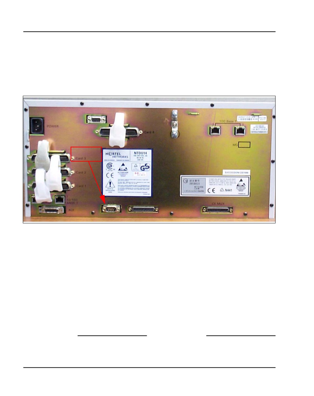
Page 284 of 466
Configuring a terminal and SDI ports
Procedure 65
Connecting SDI ports on the Media Gateways
1
Connect the NTBK48 3-port SDI cable to the 9-pin SDI port (RS-232) at
the rear of the Media Gateways (see Figure 122).
Figure 122
SDI port access to the Media Gateway SSC card
SDI
port
2
Connect the system terminal to the cable marked “port 0” on the NTBK48
3-port cable. You require a Modem Eliminator adapter to connect the
system to a TTY terminal. This adapter is included in the CS 1000E and
the Media Gateway cable kits.
3
If the system is accessed remotely, connect the system modem to the
cable marked “port 1” on the NTBK48 cable.
4
When instructed, connect the modem to an outside line.
5
When instructed, test the modem for correct operation when the system
is operating.
Note: You can use the remaining ports for other equipment, such as
CDR devices or TTYs.
End of Procedure
NN43041-310
Standard 01.11
October 2008
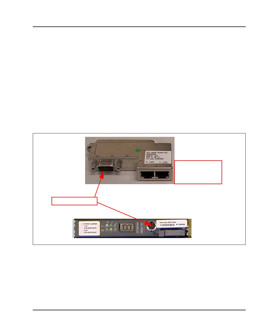
Configuring a terminal and SDI ports
Page 285 of 466
BayStack 470 SDI connection
The SDI port on the Bay Stack 470 can be used for basic configuration and
maintenance. The SDI port is located on the faceplate. It is a DCE port with
a default speed of 9600 bps.
Media Card SDI connection
The SDI ports on a Media Card can be used for basic configuration or
maintenance. Figure 123 shows the maintenance port location on the Media
Card and the Shielded 50-pin to Serial/ELAN/TLAN adapter.
Figure 123
Maintenance port location on the Media Card and the
Shielded 50-pin to Serial/ELAN/TLAN adapter
Shielded 50-pin to
Serial/ELAN/TLAN
adapter
Maintenance port
The Media Card faceplate provides a female 8-pin mini-DIN serial
maintenance port connection. The maintenance port on the Shielded 50-pin
Communication Server 1000E Installation and Commissioning
Page 286 of 466
Configuring a terminal and SDI ports
to Serial/ELAN/TLAN adapter provides an alternative to the faceplate
maintenance port. Both are DTE ports with a speed of 9600 bit/s.
CAUTION — Service Interruption
Do not connect maintenance terminals or modems to
the faceplate and I/O panel DB-9 male serial
maintenance port at the same time.
NN43041-310
Standard 01.11
October 2008
316
Page 287 of 466
Installing and cross-connecting a
trunk card
Contents
This section contains information on the following topics:
Introduction
287
Circuit card options
291
Digital trunk cards
291
Connecting a trunk
292
Universal Trunk card connections
293
E&M Trunk card connections
296
Trunk connections (Europe)
298
Trunk connections (UK)
308
Verifying trunk functionality
316
Introduction
The work order outlines the placement of circuit cards in the Media Gateway
and Media Gateway Expander. Analog trunks can be installed in both Media
Gateway and Media Gateway Expander. See Circuit Card: Description and
Installation (NN43001-311) for card placement into card slots.
Communication Server 1000E Installation and Commissioning
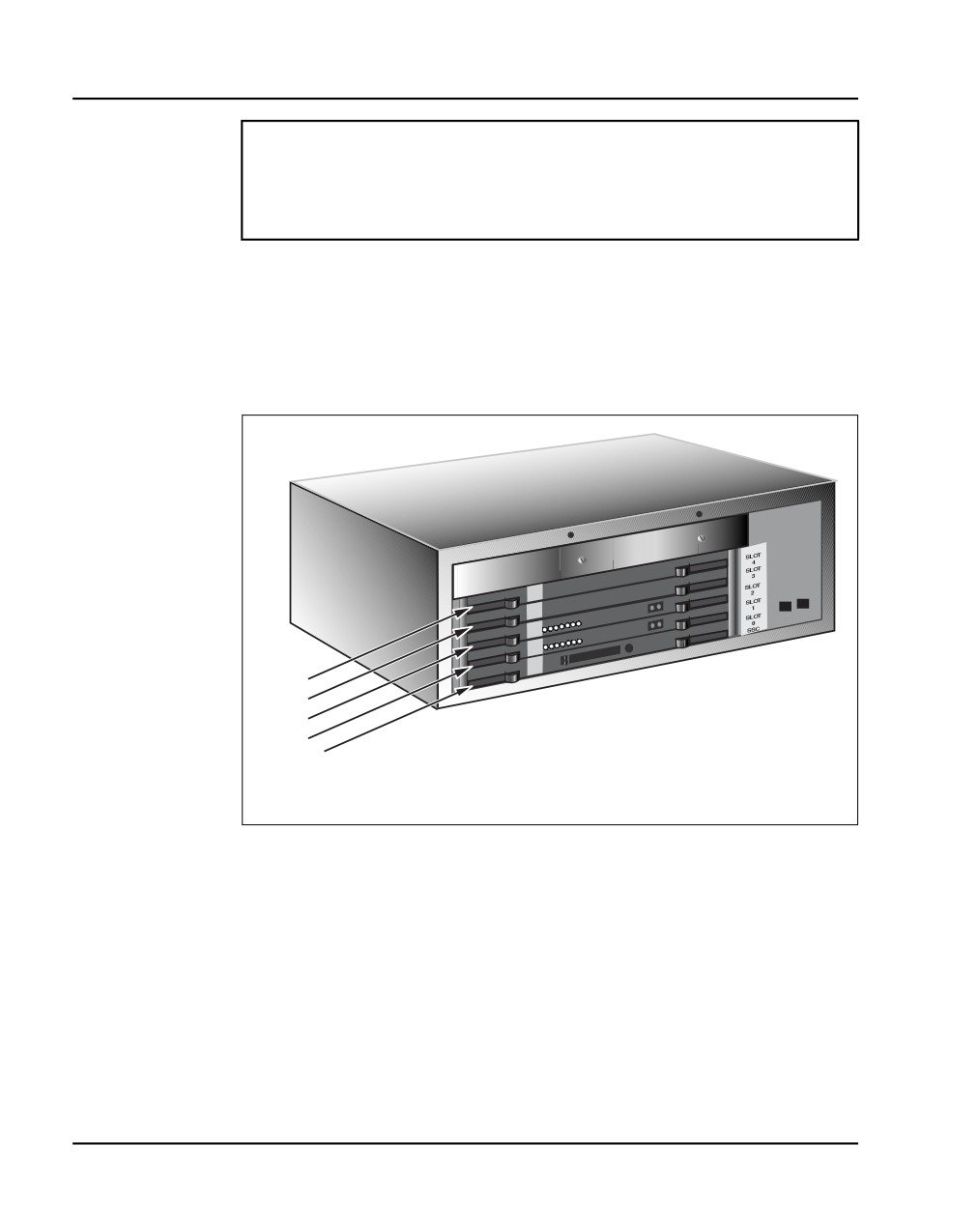
Page 288 of 466
Installing and cross-connecting a trunk card
IMPORTANT!
Digital Trunk cards can be installed only in slots 1 to 4 of the
Media Gateway.
Figure 124 shows the circuit card slots in a Media Gateway. To view the
circuit card slots available in a Media Gateway Expander, see Figure 125 on
page 289.
Figure 124
Circuit card assignments in the Media Gateway
Slot 4
Slot 3
Slot 2
Slot 1
Slot 0 - SSC
553-CSE9025
NN43041-310
Standard 01.11
October 2008
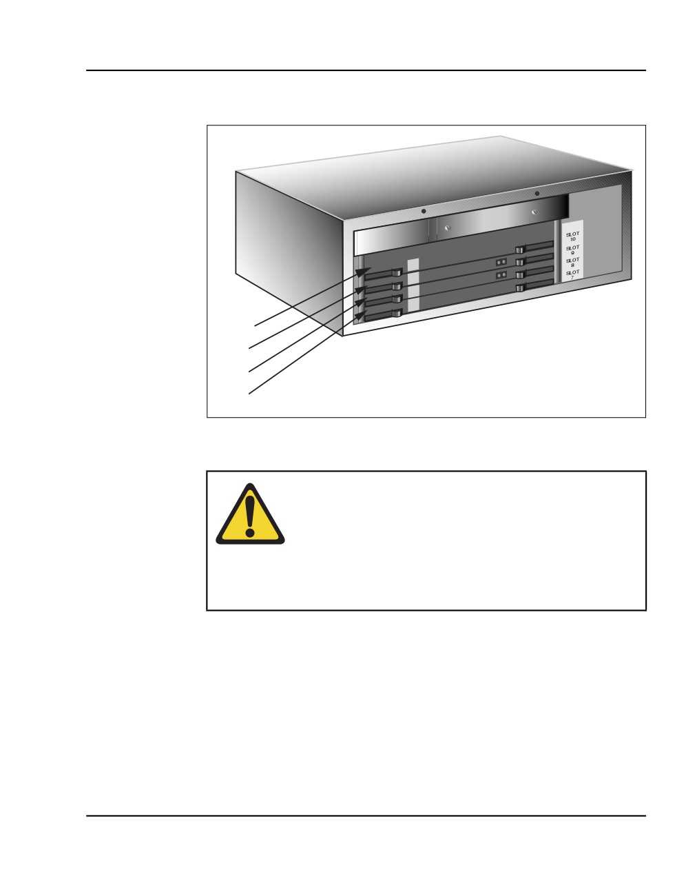
Installing and cross-connecting a trunk card
Page 289 of 466
Figure 125
Circuit card assignments in the Media Gateway Expander
Slot 10
Slot 9
Slot 8
Slot 7
553-CSE9032
WARNING
Use caution when installing or modifying telephone lines.
Avoid installing telephone wiring during a lightning storm.
Do not install telephone jacks in wet locations unless the
jacks are designed for wet locations. Never touch
uninsulated telephone wiring unless the line is
disconnected at the network interface.
Communication Server 1000E Installation and Commissioning
Page 290 of 466
Installing and cross-connecting a trunk card
Before you proceed, install the cable from the slot that contains the Line card
associated with the telephone being connected. Refer to “Installing the Main
Distribution Frame” on page 349, if you require additional cable installation.
DANGER OF ELECTRIC SHOCK
Always use caution when installing or modifying
telephone lines. Do not install telephone wiring during a
lightning storm. Do not install telephone jacks in wet
locations unless the jacks are designed for wet locations.
Never touch uninsulated telephone wiring unless the line
is disconnected at the network interface.
Refer to the Circuit Card: Description and Installation (NN43001-311) for
full descriptions of country-specific circuit cards and their installation
procedures.
CAUTION WITH ESDS DEVICES
Always handle circuit cards with caution to avoid
damage caused by static electricity. Always store circuit
cards that are not in use in an antistatic bag or the
original packaging
Wear an antistatic wrist strap, such as the one shown in
Figure 126 on page 291, when handling circuit cards.
Static electricity can damage circuit card components.
NN43041-310
Standard 01.11
October 2008
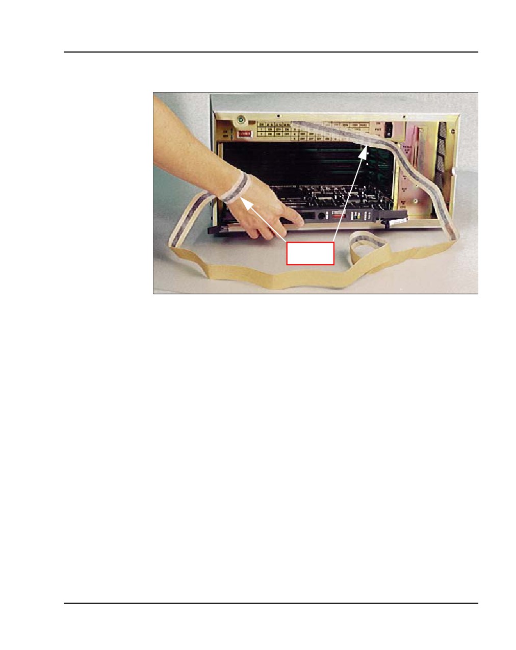
Installing and cross-connecting a trunk card
Page 291 of 466
Figure 126
Antistatic wrist strap
Antistatic
wrist strap
Circuit card options
A circuit card that has a switch symbol on its faceplate is equipped with
option switches, strapping plugs, or both. Ensure that the option switches or
strapping plugs are set correctly. Circuit cards can also have daughterboards
or other add-on devices installed on them.
Digital trunk cards
Digital trunk cards can be installed only in slots 1 to 4 in a Media Gateway.
The following Digital trunk cards can be installed:
•
NTAK09 1.5 Mbit DTI/PRI
•
NTAK10 2.0 Mbit DTI
•
NTAK79 2.0 Mbit PRI
•
NTBK22 MISP
•
NTBK50 2.0 Mbit PRI
Communication Server 1000E Installation and Commissioning
Page 292 of 466
Installing and cross-connecting a trunk card
•
NTRB21 TMDI 1.5 Mbit DTI/PRI
•
NT6D70 SILC
•
NT6D71 UILC
Note: Now NT6D70 SILC and NT6D71 UILC Digital trunk cards can
be installed in slots 7 to 10 in a Media Gateway Expander.
For additional information about installing Digital trunk cards, refer to the
following documents:
•
ISDN Primary Rate Interface: Installation and Configuration
(NN43001-301)
•
ISDN Basic Rate Interface: Installation and Configuration
(NN43001-318)
•
ISDN Primary Rate Interface: Maintenance (NN43001-717)
•
ISDN Basic Rate Interface: Maintenance (NN43001-718)
Connecting a trunk
Follow Procedure 66 to connect a trunk.
Procedure 66
Connecting a trunk
1
From the assignment record, determine the location of the trunk
connection and its associated Terminal Number (TN) at the
cross-connect terminal.
2
With cross-connect wire, connect the trunk to the TN.
Make sure that the wiring is not reversed and that it is on the correct
terminals.
•
Table 24 on page 293 to Table 26 on page 296 list the connections
for trunks.
•
For European trunk connections, see Table 27 on page 298 to
Table 35 on page 307.
•
For UK trunk connections, see Table 36 on page 309 to Table 42 on
page 316.
NN43041-310
Standard 01.11
October 2008

Installing and cross-connecting a trunk card
Page 293 of 466
Note: See “Installing and cross-connecting a Power Fail Transfer Unit”
on page 437 for connecting trunks with the PFTU.
End of Procedure
Universal Trunk card connections
The Universal Trunk card (NT8D14) provides eight Analog trunks that can
function in the modes identified in Table 24. Refer to Table 25 on page 294
for the connections to the Universal trunk at the cross-connect terminal.
Table 24
NT8D14 Universal Trunk card - modes and option settings
Modes
Location
Jumper strap
Central (CO)
J1, J2
OFF
2-way TIE trunk (loop Dial Repeat)
J1, J2
OFF
2-way TIE trunk (Outgoing Incoming
J1, J2
OFF
Dial)
Recorded Announcement (RAN)
J1, J2
OFF
Paging trunk
J1, J2
OFF
Japan CO/DID operation
J1, J2
OFF
DID operation
J1, J2
ON
Loop length>2000 ohms
DID operation
J1, J2
OFF
Loop length <2000 ohms
Note 1: OFF indicates that no strap is present.
Note 2: J1 and J2 locations apply to all eight trunks.
Communication Server 1000E Installation and Commissioning

Page 294 of 466
Installing and cross-connecting a trunk card
Table 25
NT8D14 Universal Trunk connections (Part 1 of 2)
RAN
Paging
All other
Cable from equipment
Unit
mode
mode
modes
Pair
Color
Designations
1T
W-BL
T0
T0
T0
1R
BL-W
R0
R0
R0
0
2T
W-O
CP
A
2R
O-W
MB
PG
3T
W-G
T1
T1
T1
3R
G-W
R1
R1
R1
1
4T
W-BR
CP
A
4R
BR-W
MB
PG
5T
W-S
T2
T2
T2
5R
S-W
R2
R2
R2
2
6T
R-BL
CP
A
6R
BL-R
MB
PG
7T
R-O
T3
T3
T3
7R
O-R
R3
R3
R3
3
8T
R-G
CP
A
8R
G-R
MB
PG
9T
R-BR
T4
T4
T4
9R
BR-R
R4
R4
R4
4
10T
R-S
CP
A
10R
S-R
MB
PG
11T
BK-BL
T5
T5
T5
11R
BL-BK
R5
R5
R5
5
12T
BK-O
CP
A
12R
O-BK
MB
PG
NN43041-310
Standard 01.11
October 2008

Installing and cross-connecting a trunk card
Page 295 of 466
Table 25
NT8D14 Universal Trunk connections (Part 2 of 2)
RAN
Paging
All other
Cable from equipment
Unit
mode
mode
modes
Pair
Color
Designations
13T
BK-G
T6
T6
T6
13R
G-BK
R6
R6
R6
6
14T
BK-BR
CP
A
14R
BR-BK
MB
PG
15T
BK-S
T7
T7
T7
15R
S-BK
R7
R7
R7
7
16T
Y-BL
CP
A
16R
BL-Y
MB
PG
Note: Remaining pairs are spare.
Communication Server 1000E Installation and Commissioning

Page 296 of 466
Installing and cross-connecting a trunk card
E&M Trunk card connections
Table 26 lists the connections required by the E&M Trunk card (NT8D15).
Table 26
NT8D15 E&M Trunk card (Part
1 of 2)
Cables
Card 1 through
2W
2W
4W
4W
Card 10 from
Paging
Type 1
Type 1
Type 2
equipment
Unit
mode
mode
mode
mode
Pair
Color
Designations
1T
W-BL
T0
T0
TA
TA
BL-W
R0
R0
TB
TB
1R
2T
W-O
RA
RA
2R
O-W
RB
RB
0
3T
W-G
E
E
EA
3R
G-W
M
M
EB
4T
W-BR
A
ESC
MA
4R
BR-W
PG
ESCG
MB
5T
W-S
T1
T1
TA
TA
5R
S-W
R1
R1
TB
TB
6T
R-BL
RA
RA
6R
BL-R
RB
RB
1
7T
R-O
E
E
EA
7R
O-R
M
M
EB
8T
R-G
A
ESC
MA
8R
G-R
PG
ESCG
MB
NN43041-310
Standard 01.11
October 2008

Installing and cross-connecting a trunk card
Page 297 of 466
Table 26
NT8D15 E&M Trunk card (Part
2 of 2)
Cables
Card 1 through
2W
2W
4W
4W
Card 10 from
Paging
Type 1
Type 1
Type 2
equipment
Unit
mode
mode
mode
mode
Pair
Color
Designations
9T
R-BR
T2
T2
TA
TA
9R
BR-R
R2
TB
TB
R2
10T
R-S
RA
RA
10R
S-R
RB
RB
2
11T
BK-BL
E
E
EA
11R
BL-BK
M
M
EB
12T
BK-O
A
ESC
MA
12R
O-BK
PG
ESCG
MB
13T
BK-G
T3
T3
TA
TA
13R
G-BK
R3
R3
TB
TB
14T
BK-BR
RA
RA
14R
BR-BK
RB
RB
3
15T
BK-S
E
E
EA
15R
S-BK
M
M
EB
16T
Y-BL
A
ESC
MA
16R
BL-Y
PG
ESCG
MB
Note:
A and B are the transmit and receive pairs, where:
TA = Transmit Tip, and RA = Receive Tip
TB = Transmit Ring, and RB = Receive Ring
Communication Server 1000E Installation and Commissioning

Page 298 of 466
Installing and cross-connecting a trunk card
Trunk connections (Europe)
Trunk connections for Europe are provided in the following tables:
•
Table 27: “E&M TIE trunk card (2-Wire)” on page 298
•
Table 28: “E&M 2-wire Type 2” on page 299
•
Table 29: “E&M TIE Trunk card (4-Wire)” on page 300
•
Table 30: “E&M TIE Trunk card” on page 302
•
Table 31: “E&M 2280 Hz TIE Trunk connections” on page 303
•
Table 32: “E&M 2-wire Recorded Announcement Trunk connections”
on page 304
•
Table 33: “E&M 2-wire Music Trunk connections” on page 305
•
Table 34: “Central Office & Direct Dial Inward Trunk connections” on
page 305
•
Table 35: “Central Office Trunk connections” on page 307
Table 27
E&M TIE trunk card (2-Wire) (Part 1 of 2)
Column 3
Cables Card 1 through Card 10
Column 1
Column 2
Type 5
from equipment
Paging
Paging
(BPO)
Pair
Color
Unit
Pins
Lead Designations
1T
W-O
27
T0
T0
T0
1R
O-W
2
R0
R0
R0
0
2T
W-BR
29
A
SIGB
E
2R
BR-W
4
PG
SIGA
M
3T
R-BL
31
T1
T1
T1
3R
BL-R
6
R1
R1
R1
1
4T
R-G
33
A
SIGB
E
4R
G-R
8
PG
SIGA
M
NN43041-310
Standard 01.11
October 2008

Installing and cross-connecting a trunk card
Page 299 of 466
Table 27
E&M TIE trunk card (2-Wire) (Part 2 of 2)
Column 3
Cables Card 1 through Card 10
Column 1
Column 2
Type 5
from equipment
Paging
Paging
(BPO)
5T
R-S
35
T2
T2
T2
5R
S-R
10
R2
R2
R2
2
6T
BK-O
37
A
SIGB
E
6R
O-BK
12
PG
SIGA
M
7T
BK-BR
39
T3
T3
T3
7R
BR-BK
14
R3
R3
R3
3
8T
Y-BL
41
A
SIGB
E
8R
BL-Y
16
PG
SIGA
M
Table 28
E&M 2-wire Type 2 (Part
1 of 2)
Lead
designations
Pins
Pair color
Unit number
T0
27
W-O
R0
2
O-W
E1
28
W-G
E2
3
G-W
0
M1
29
W-G
M2
4
G-W
T1
31
R-BL
R1
6
BL-R
E1
32
R-O
E2
7
O-R
1
M1
33
R-G
M2
8
G-R
Communication Server 1000E Installation and Commissioning

Page 300 of 466
Installing and cross-connecting a trunk card
Table 28
E&M 2-wire Type 2 (Part 2 of 2)
T2
35
R-S
R2
10
S-R
E1
36
BK-BL
E2
11
BL-BK
2
M1
37
BK-O
M2
12
O-BK
T3
39
BK-BR
R3
14
BR-BK
E1
40
BK-S
E2
15
S-BK
3
M1
41
Y-BL
M2
16
BL-Y
Table 29
E&M TIE Trunk card (4-Wire) (Part 1
of
2)
Cables Card 1 through
Column 1
Column 2
Card 10 from equipment
Type 1 & 5
Type 1 & 5
Unit
Pair
Color
#
Pins
Lead Designations
1T
W-BL
26
RA
TA
1R
BL-W
1
RB
TB
2T
W-O
27
TA
RA
2R
O-W
2
TB
RB
0
3T
W-G
28
E
E
3R
G-W
3
M
M
NN43041-310
Standard 01.11
October 2008