Nortel Communication Server 1000. Installation And Commissioning Manual (2008) - page 4

Installing and cross-connecting a trunk card
Page 301 of 466
Table 29
E&M TIE Trunk card (4-Wire) (Part 2 of
2)
Cables Card 1 through
Column 1
Column 2
Card
10 from equipment
Type 1 & 5
Type 1 & 5
4T
W-S
30
RA
TA
4R
S-W
5
RB
TB
5T
R-BL
31
TA
RA
5R
BL-R
6
TB
RB
1
6T
R-O
32
E
E
6R
O-R
7
M
M
7T
R-BR
34
RA
TA
7R
BR-R
9
RB
TB
8T
R-S
35
TA
RA
8R
S-R
10
TB
RB
2
9T
BK-BL
36
E
E
9R
BL-BK
11
M
M
10T
BK-G
38
RA
TA
10R
G-BK
13
RB
TB
11T
BK-BR-
39
TA
RA
11R
BR-BK
14
TB
RB
3
12T
BK-S
40
E
E
12R
S-BK
15
M
M
Note:
The cable pair designated TA, TB is the transmit pair. The pair
designated RA, RB is the receive pair.
Communication Server 1000E Installation and Commissioning

Page 302 of 466
Installing and cross-connecting a trunk card
Table 30
E&M TIE Trunk card (Part 1 of
2)
Cables Card 1 through
Column 1
Column 2
Card 10 from equipment
Type 2
Type 2
Unit
Pair
Color
#
Pins
Lead Designations
1T
W-BL
26
RA
RA
1R
BL-W
1
RB
RB
2T
W-O
27
TA
TA
2R
O-W
2
TB
TB
0
3T
W-G
28
E1
E
3R
G-W
3
E2
M
4T
W-BR
29
M1
SIG0A
4R
BR-W
4
M2
SIG0B
5T
W-S
30
RA
RA
5R
S-W
5
RB
RB
6T
R-BL
31
TA
TA
6R
BL-R
6
TB
TB
1
7T
R-O
32
E1
E
7R
O-R
7
E2
M
8T
R-G
33
M1
SIG1A
8R
G-R
8
M2
SIG1B
9T
R-BR
34
RA
RA
9R
BR-R
9
RB
RB
10T
R-S
35
TA
TA
10R
S-R
10
TB
TB
2
11T
BK-BL
36
E1
E
11R
BL-BK
11
E2
M
12T
BK-O
37
M1
SIG2A
12R
O-BK
12
M2
SIG2B
NN43041-310
Standard 01.11
October 2008

Installing and cross-connecting a trunk card
Page 303 of 466
Table 30
E&M TIE Trunk card (Part 2 of 2)
Cables Card 1 through
Column 1
Column 2
Card 10 from equipment
Type 2
Type 2
13T
BK-G
38
RA
RA
13R
G-BK
13
RB
RB
3
14T
BK-BR
39
TA
TA
14R
BR-BK
14
TB
TB
15T
BK-S
40
E1
E
15R
S-BK
15
E2
M
16T
Y-BL
41
M1
SIG3A
16R
BL-Y
16
M2
SIG3B
Note: The cable pair designated TA, TB is the transmit pair. The pair
designated RA, RB is the receive pair.
Table 31
E&M 2280 Hz TIE Trunk connections (Part 1 of 2)
Lead
designations
Pins
Pair color
Unit number
TA
26
W-BL
TB
1
BL-W
0
RA
27
W-O
RB
2
O-W
TA
30
W-S
TB
5
S-W
1
RA
31
R-BL
6
BL-R
RB
Communication Server 1000E Installation and Commissioning

Page 304 of 466
Installing and cross-connecting a trunk card
Table 31
E&M 2280 Hz TIE Trunk connections (Part 2 of 2)
TA
34
R-BR
TB
9
BR-R
2
RA
35
R-S
RB
10
S-R
TA
38
BK-G
TB
13
G-BK
3
RA
39
BK-BR
RB
14
BR-BK
Table 32
E&M 2-wire Recorded Announcement Trunk connections
Lead
designations
Pins
Pair color
Unit number
T0
26
W-BL
R0
1
BL-W
0
SIG B
29
W-BR
SIG A
4
BR-W
T1
30
W-S
R1
5
S-W
1
SIG B
33
R-G
SIG A
8
G-R
T2
34
R-BR
R2
9
BR-R
2
SIG B
37
BK-O
SIG A
12
O-BK
T3
38
BK-G
R3
13
G-BK
3
SIG B
41
Y-BL
SIG A
16
BL-Y
NN43041-310
Standard 01.11
October 2008

Installing and cross-connecting a trunk card
Page 305 of 466
Table 33
E&M 2-wire Music Trunk connections
Lead
designations
Pins
Pair color
Unit number
T0
26
W-BL
R0
1
BL-W
0
T1
30
W-S
R1
5
S-W
1
T2
34
R-BR
R2
9
BR-R
2
T3
38
BK-G
R3
13
G-BK
3
Table 34
Central Office & Direct Dial Inward Trunk connections (Part 1 of 2)
Cable from
equipment
Column 1
Column 2
Column 3
Pair
Color
Unit
Pins
Lead designations
1T
W-BL
26
T0
T0
A0
1R
BL-W
1
R0
R0
B0
0
2T
W-O
27
PPM0
C0
2R
O-W
2
—
Spare
3T
W-G
28
T1
T1
A1
3R
G-W
3
R1
R1
B1
1
4T
W-BR
29
PPM1
C1
4R
BR-W
4
—
Spare
5T
W-S
30
T2
T2
A2
5R
S-W
5
R2
R2
B2
2
6T
R-BL
31
PPM2
C2
6R
BL-R
6
—
Spare
Communication Server 1000E Installation and Commissioning

Page 306 of 466
Installing and cross-connecting a trunk card
Table 34
Central Office & Direct Dial Inward Trunk connections (Part 2 of 2)
Cable from
equipment
Column 1
Column 2
Column 3
Pair
Color
Unit
Pins
Lead designations
7T
R-O
32
T3
T3
A3
7R
O-R
7
R3
R3
B3
3
8T
R-G
33
PPM3
C3
8R
G-R
8
—
Spare
9T
R-BR
34
T4
T4
A4
9R
BR-R
9
R4
R4
B4
4
10T
R-S
35
PPM4
C4
10R
S-R
10
—
Spare
11T
BK-BL
36
T5
T5
A5
11R
BL-BK
11
R5
R5
B5
5
12T
BK-O
37
PPM5
C5
12R
O-BK
12
—
Spare
13T
BK-G
38
T6
T6
A6
13R
G-BK
13
R6
R6
B6
6
14T
BK-BR
39
PPM6
C6
14R
BR-BK
14
—
Spare
15T
BK-S
40
T7
T7
A7
15R
S-BK
15
R7
R7
B7
7
16T
Y-BL
41
PPM7
C7
16R
BL-Y
16
—
Spare
NN43041-310
Standard 01.11
October 2008

Installing and cross-connecting a trunk card
Page 307 of 466
Table 35
Central Office Trunk connections (Part
1 of 2)
Cable from
equipment
Pair
Color
Unit
Pins
Lead designations
1T
W-BL
26
T0
1R
BL-W
1
R0
2T
W-O
27
2R
O-W
2
0
3T
W-G
28
3R
G-W
3
4T
W-BR
29
4R
BR-W
4
5T
W-S
30
T1
5R
S-W
5
R1
6T
R-BL
31
6R
BL-R
6
1
7T
R-O
32
7R
O-R
7
8T
R-G
33
8R
G-R
8
9T
R-BR
34
T2
9R
BR-R
9
R2
10T
R-S
35
10R
S-R
10
2
11T
BK-BL
36
11R
BL-BK
11
12T
BK-O
37
12R
O-BK
12
Communication Server 1000E Installation and Commissioning
Page 308 of 466
Installing and cross-connecting a trunk card
Table 35
Central Office Trunk connections (Part 2 of 2)
Cable from
equipment
Pair
Color
Unit
Pins
Lead designations
13T
BK-G
38
T3
13R
G-BK
13
R3
14T
BK-BR
39
14R
BR-BK
14
3
15T
BK-S
40
15R
S-BK
15
16T
Y-BL
41
16R
BL-Y
16
Trunk connections (UK)
Trunk connections for the UK are provided in the following tables:
•
Table 36: “NT5K17 Direct Inward Dial card terminations” on page 309
•
Table 37: “NT5K18 Exchange line trunk card cross-connect
terminations” on page 310
•
Table 38: “NT5K19 2W paging mode terminations” on page 312
•
Table 39: “NT5K19 2W Type 1 mode terminations” on page 312
•
Table 40: “NT5K19 4W Type 1 mode terminations” on page 314
•
Table 41: “NT5K19 AC15 mode pair terminations” on page 315
•
Table 42: “NT5K19 Recorded Announcement mode pair terminations”
on page 316
NN43041-310
Standard 01.11
October 2008
Installing and cross-connecting a trunk card
Page 309 of 466
Table 36
NT5K17 Direct Inward Dial card terminations (Part 1 of 2)
Pair
Pins
Pair color
Unit
T0
26
W-BL
R0
1
BL-W
0
27
W-O
2
O-W
T1
28
W-G
R1
3
G-W
1
29
W-BR
4
BR-W
T2
30
W-S
R2
5
S-W
2
31
R-BL
6
BL-R
T3
32
R-O
R3
7
O-R
3
33
R-G
8
G-R
T4
34
R-BR
R4
9
BR-R
4
35
R-S
10
S-R
T5
36
BK-BL
R5
11
BL-BK
5
37
BK-O
12
O-BK
T6
38
BK-G
R6
13
G-BK
6
Communication Server 1000E Installation and Commissioning

Page 310 of 466
Installing and cross-connecting a trunk card
Table 36
NT5K17 Direct Inward Dial card terminations (Part 2 of 2)
Pair
Pins
Pair color
Unit
39
BK-BR
14
BR-BK
T7
40
BK-S
R7
15
S-BK
7
41
Y-BL
16
BL-Y
Note: The connections on the NT5K18 Exchange Line Trunk card are
polarity-sensitive. Make sure the ground side of the trunk is connected to
the A leg of the NT5K18 circuit. Make sure the -50 Volt side of the trunk
is connected to the B leg of the NT5K18 circuit.
Table 37
NT5K18 Exchange line trunk card cross-connect terminations
(Part 1 of 2)
Pair
Pins
Pair color
Unit
T0
26
W-BL
R0
1
BL-W
0
27
W-O
2
O-W
T1
28
W-G
R1
3
G-W
1
29
W-BR
4
BR-W
T2
30
W-S
R2
5
S-W
2
31
R-BL
6
BL-R
NN43041-310
Standard 01.11
October 2008
Installing and cross-connecting a trunk card
Page 311 of 466
Table 37
NT5K18 Exchange line trunk card cross-connect terminations
(Part 2
of
2)
Pair
Pins
Pair color
Unit
T3
32
R-O
R3
7
O-R
3
33
R-G
8
G-R
T4
34
R-BR
R4
9
BR-R
4
35
R-S
10
S-R
T5
36
BK-BL
R5
11
BL-BK
5
37
BK-O
12
O-BK
T6
38
BK-G
R6
13
G-BK
6
39
BK-BR
14
BR-BK
T7
40
BK-S
R7
15
S-BK
7
41
Y-BL
16
BL-Y
Communication Server 1000E Installation and Commissioning
Page 312 of 466
Installing and cross-connecting a trunk card
Note: The speech pairs on the NT5K19 card are polarity-insensitive.
The E&M signaling pairs, however, are polarity-sensitive. Make sure the
ground side of the trunk is connected to the A leg of the NT5K19 circuit.
Make sure the -50 Volt side of the trunk is connected to the B leg.
Table 38
NT5K19 2W paging mode terminations
Pair
Pins
Pair color
Unit
T0
27
W-O
R0
2
O-W
0
A
29
W-BR
PG
4
BR-W
T1
31
R-BL
R1
6
BL-R
1
A
33
R-G
PG
8
G-R
T2
35
R-S
R2
10
S-R
2
A
37
BK-O
PG
12
O-BK
T3
39
BK-BR
R3
14
BR-BK
3
A
41
Y-BL
PG
16
BL-Y
Table 39
NT5K19 2W Type 1 mode terminations (Part 1 of 2)
Pair
Pins
Pair color
Unit
T0
27
W-O
R0
2
O-W
0
E
28
W-G
M
3
G-W
NN43041-310
Standard 01.11
October 2008

Installing and cross-connecting a trunk card
Page 313 of 466
Table 39
NT5K19 2W Type 1 mode terminations (Part 2 of 2)
Pair
Pins
Pair color
Unit
T1
31
R-BL
R1
6
BL-R
1
E
32
R-O
M
&
O-R
T2
35
R-S
R2
10
S-R
2
E
36
BK-BL
M
11
BL-BK
T3
39
BK-BR
R3
14
BR-BK
3
E
40
BK-S
M
15
S-BK
Communication Server 1000E Installation and Commissioning
Page 314 of 466
Installing and cross-connecting a trunk card
Table 40
NT5K19 4W Type 1 mode terminations
Pair
Pins
Pair color
Unit
TA
26
W-BL
TB
1
BL-W
RA
27
W-O
RB
2
O-W
0
E
28
W-G
M
3
G-W
RA
30
W-S
RB
5
S-W
TA
31
R-BL
RB
6
BL-R
1
E
32
R-O
M
7
O-R
TA
34
R-BR
TB
9
BR-R
RA
35
R-S
RB
10
S-R
2
E
36
BK-BL
M
11
BL-BK
TA
38
BK-G
TB
13
G-BK
RA
39
BK-BR
TB
14
BR-BK
3
E
40
BK-S
M
15
S-BK
NN43041-310
Standard 01.11
October 2008

Installing and cross-connecting a trunk card
Page 315 of 466
Table 41
NT5K19 AC15 mode pair terminations
Pair
Pins
Pair color
Unit
TA
26
W-BL
TB
1
BL-W
0
RA
27
W-O
RB
2
O-W
TA
30
W-S
TB
5
S-W
1
RA
31
R-BL
RB
6
BL-R
TA
34
R-BR
TB
9
BR-R
2
RA
35
R-S
RB
10
S-R
TA
38
BK-G
TB
13
G-BK
3
RA
39
BK-BR
TB
14
BR-BK
Communication Server 1000E Installation and Commissioning

Page 316 of 466
Installing and cross-connecting a trunk card
Table 42
NT5K19 Recorded Announcement mode pair terminations
Pair
Pins
Pair color
Unit
T0
26
W-BL
R0
1
BL-W
0
SIG B
29
W-BR
SIG A
4
BR-W
T1
30
W-S
R1
5
S-W
1
SIG B
33
R-G
SIG A
8
G-R
T2
34
R-BR
R2
9
BR-R
2
SIG B
37
BK-O
SIG A
12
O-BK
T3
38
BK-G
R3
13
G-BK
3
SIG B
41
Y-BL
SIG A
16
BL-Y
Verifying trunk functionality
You can now use the trunks. To test the trunks, make trunk calls.
NN43041-310
Standard 01.11
October 2008
348
Page 317 of 466
Installing and configuring a
Voice Gateway Media Card
Contents
This section contains information on the following topics:
Introduction
318
Configuring a card
319
Adding a card to an IP telephony node
319
Configuring a card as a node Leader
322
Configuring voice gateway channels using Element Manager
323
Configuring voice gateway channels using LD 14
325
Saving configuration changes
327
Installing a CompactFlash
328
Installing a card in a Media Gateway
333
Verifying a card
336
Disabling a card
344
Disabling a card unit
345
Enabling a card
346
Enabling a card unit
347
Verifying functionality
348
Upgrading loadware
348
Communication Server 1000E Installation and Commissioning
Page 318 of 466
Installing and configuring a Voice Gateway Media Card
Introduction
The Voice Gateway Media Card provides access to the voice gateway and
functions as a Follower to the Signaling Server, which is the node Leader and
which, by default, acts as a Master for the node. In the absence of the
Signaling Server a Voice Gateway Media Card may be an active Leader, a
backup Leader, or a Follower. Each customer in a system has only one
Leader.
A Voice Gateway Media Card runs the IP Line 3.1 software. It provides voice
gateway channels (DSPs) to transcode voice data between IP and TDM
(analog/digital). The card’s node properties, as well as the voice gateway
channels, must be configured. The cards are installed in a Media Gateway or
a Media Gateway Expander.
The Voice Gateway Media Card is represented by a Media Card 32-Port IP
Line 3.1/Voice Gateway.
For details, see IP Line: Description, Installation, and Operation
(NN43100-500).
This chapter contains the following procedures:
•
Procedure 67: "Adding a Voice Gateway Media Card to an IP telephony
node" on page 319
•
Procedure 68: "Adding voice gateway channels using Element Manager"
on page 323
•
Procedure 69: "Configuring voice gateway channels using LD 14" on
page 326
•
Procedure 70: "Installing the CompactFlash" on page 330
•
Procedure 71: "Installing a Voice Gateway Media Card in a card slot" on
page 335
•
Procedure 72: "Displaying the Voice Gateway Media Card status" on
page 336
•
Procedure 73: "Displaying the Voice Gateway status
for all voice gateway channels" on page 338
NN43041-310
Standard 01.11
October 2008
Installing and configuring a Voice Gateway Media Card Page 319 of 466
•
Procedure 74: "Displaying the status of Voice Gateway Media Card
units" on page 341
•
Procedure 75: "Displaying the status of one unit on a Voice Gateway
Media Card" on page 344
•
Procedure 76: "Disabling a Voice Gateway Media Card using Element
Manager" on page 344
•
Procedure 77: "Disabling a Voice Gateway Media Card unit using
Element Manager" on page 345
•
Procedure 78: "Enabling a Voice Gateway Media Card using Element
Manager" on page 346
•
Procedure 79: "Enabling a Voice Gateway Media Card unit using
Element Manager" on page 347
Configuring a card
A Voice Gateway Media Card requires configuration of:
•
the IP telephony properties defined with Element Manager (the Voice
Gateway Media Cards are assigned to an IP telephony node). See
“Configuring an IP telephony node” on page 361.
•
the voice gateway channels defined on the CS 1000E. See “Configuring
voice gateway channels using Element Manager” on page 323.
Adding a card to an IP telephony node
The Voice Gateway Media Card is added to an IP telephony node using
Element Manager only. See Element Manager: System Administration
(NN43001-632) for details.
Procedure 67
Adding a Voice Gateway Media Card to an IP telephony node
1
Log in to Element Manager.
2
Select IP Network > Nodes: Servers, Media Cards from the navigator.
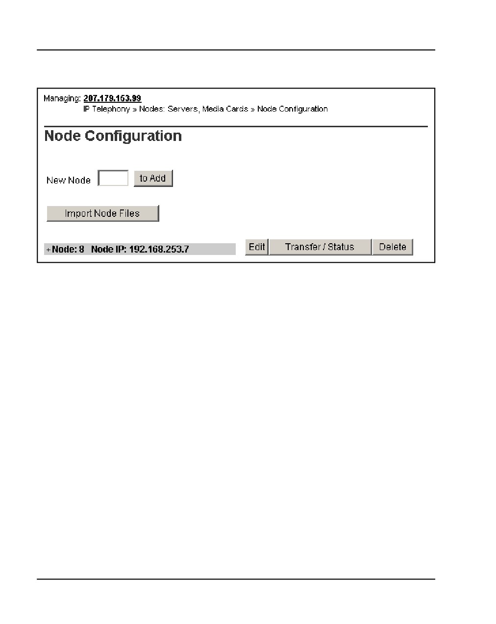
The Node Configuration web page opens, as shown in Figure 127.
Communication Server 1000E Installation and Commissioning
Page 320 of 466
Installing and configuring a Voice Gateway Media Card
Figure 127
Node Configuration web page
3
Click Edit next to the Node to which the Voice Gateway Media Card is to
be added.
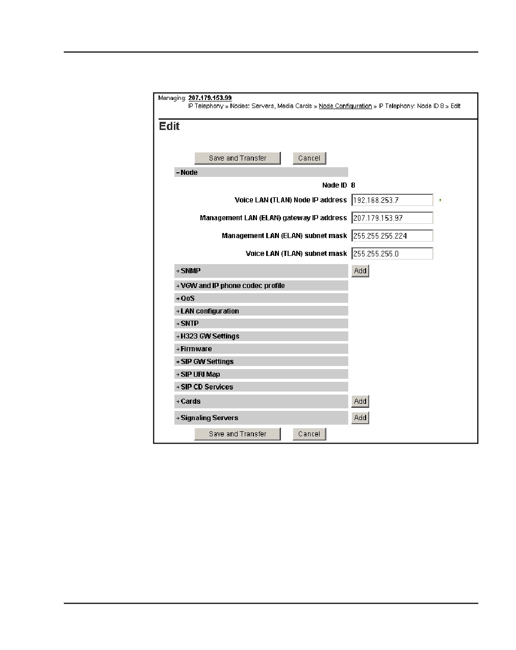
The Edit web page opens, as shown in Figure 128 on page 321.
NN43041-310
Standard 01.11
October 2008
Installing and configuring a Voice Gateway Media Card Page 321 of 466
Figure 128
Edit web page
4
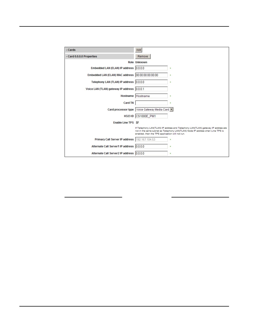
Click Add next to the Cards tab.
The Cards tab expands (see Figure 129 on page 322).
5
Enter your data for this Voice Gateway Media Card. The ELAN MAC
address is on a faceplate sticker. The TN is the Voice Gateway Media
Card logical card slot.
Note: For more detail on Voice Gateway Media Card properties, see
IP Line: Description, Installation, and Operation
(NN43100-500).
Communication Server 1000E Installation and Commissioning
Page 322 of 466
Installing and configuring a Voice Gateway Media Card
Figure 129
Cards
6
Save the node.
a. Click Save and Transfer at the bottom of the Edit web page
b. Click OK to save this node.
End of Procedure
Configuring a card as a node Leader
A Voice Gateway Media Card remains at the default “Follower” setting in a
CS 1000E system. A Signaling Server is the IP telephony node Leader.
In an IP telephony node without a Signaling Server, one of the Voice
Gateway Media Cards must be configured as a Leader. If this is your
configuration, see the IP Line: Description, Installation, and Operation
(NN43100-500) for a detailed configuration procedure.
Normally, Voice Gateway Media Cards default as Followers. If you need to
configure a Voice Gateway Media Card as a Follower, see the IP Line:
NN43041-310
Standard 01.11
October 2008
Installing and configuring a Voice Gateway Media Card Page 323 of 466
Description, Installation, and Operation (NN43100-500) for a detailed
configuration procedure.
Configuring voice gateway channels using
Element Manager
The voice gateway channels are also called “DSP channels” or the card’s
“physical TNs”. Follow Procedure 68 to configure the voice gateway
channels using Element Manager.
Note: The voice gateway channels can also be configured using LD 14.
To configure the voice gateway channels using LD 14, follow
Procedure 69 on page 326.
Procedure 68
Adding voice gateway channels using Element Manager
1
Select IP Network > Nodes: Servers, Media Cards from the navigator.
The Node Configuration web page opens, as shown in Figure 127 on
page 320.
2
Click the + next to the desired node to expand it.
3
Click VGW Channels next to the desired card.
If no VGW channels are configured yet, an alert box is displays. Click OK
to close the alert box.
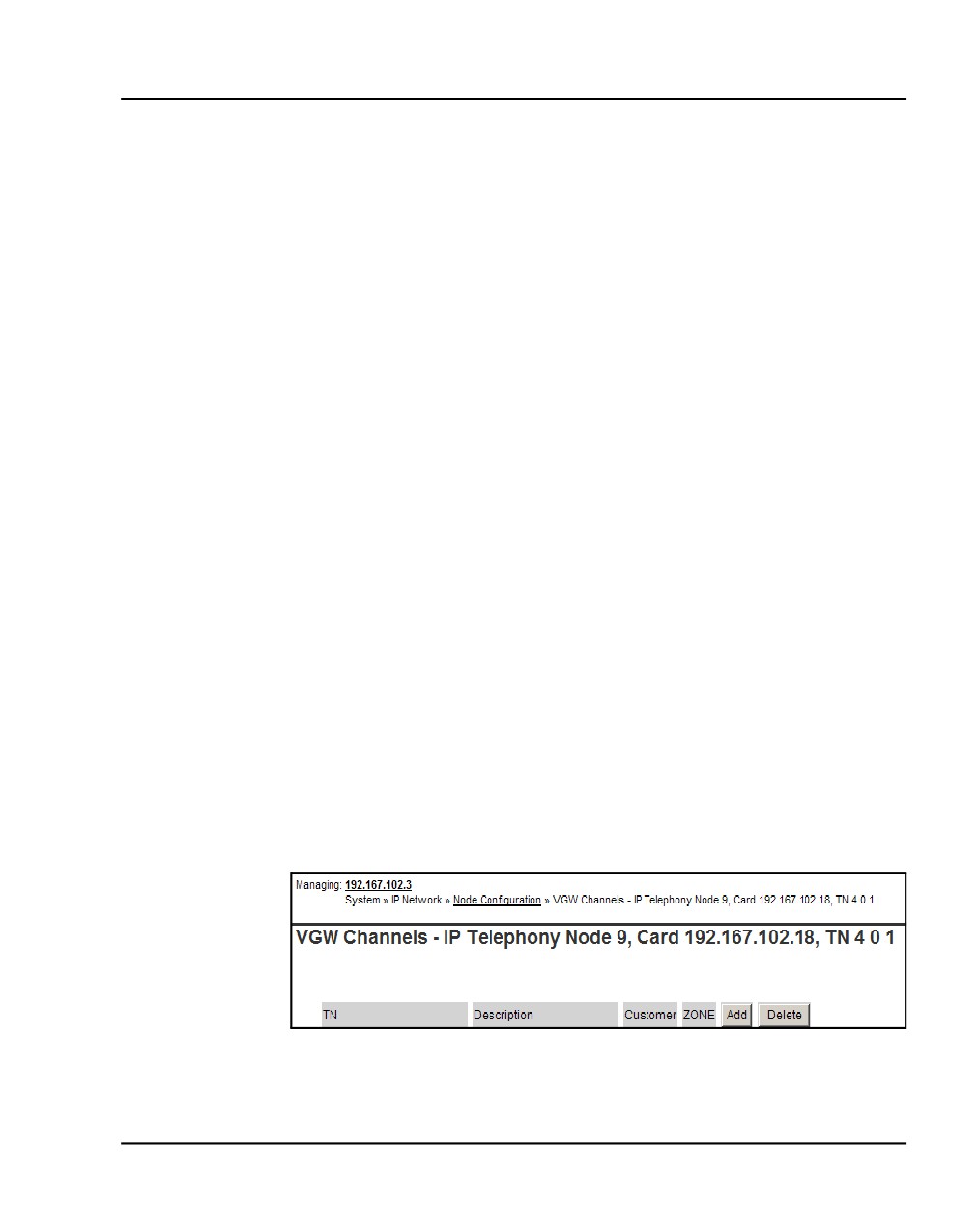
The VGW channels configuration for this card opens, as shown in
Figure 130.
Figure 130
VGW Channel web page
4
Click Add.
Communication Server 1000E Installation and Commissioning
Page 324 of 466
Installing and configuring a Voice Gateway Media Card
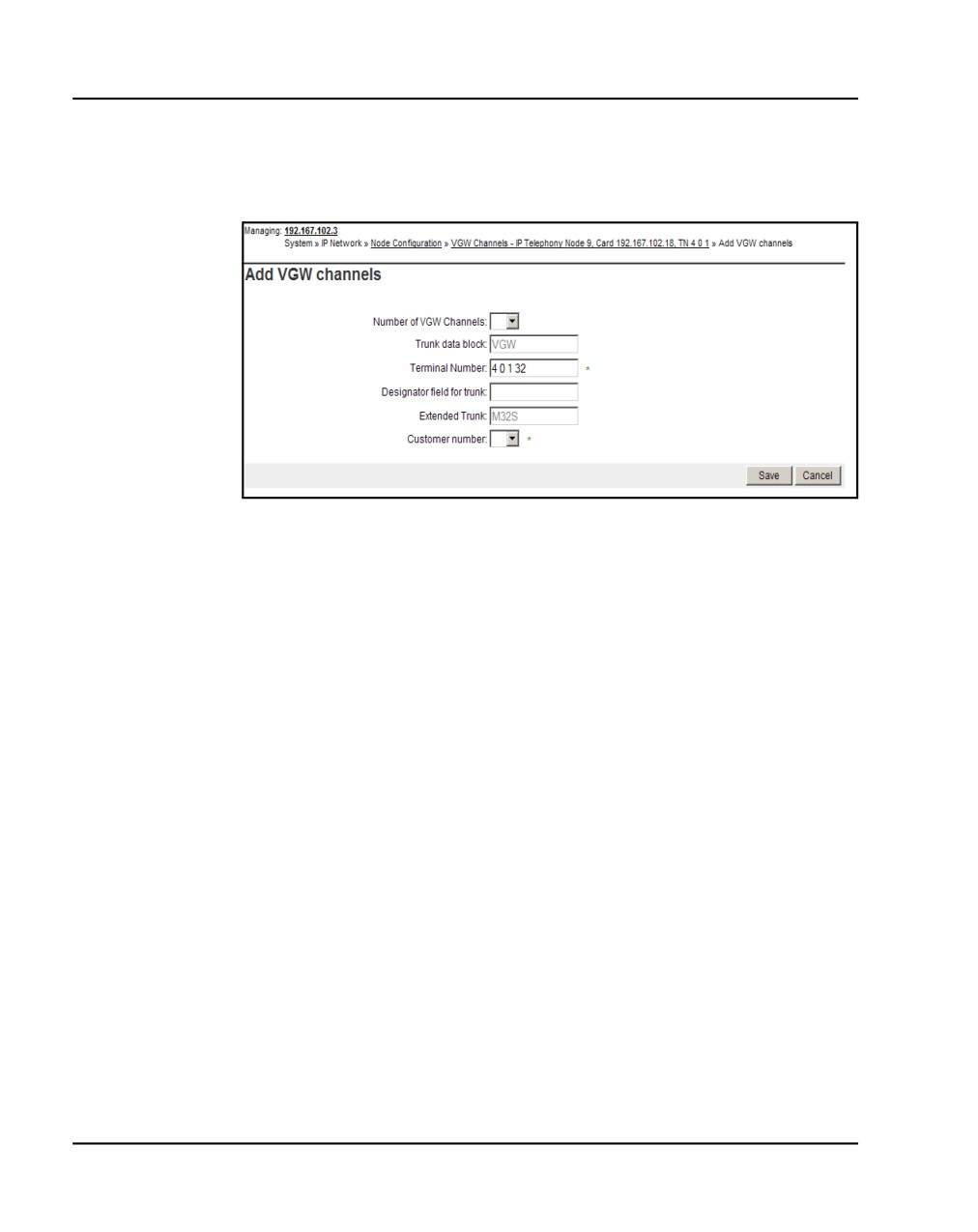
The Add VGW channels web page opens, as shown in Figure 131.
Figure 131
Add VGW channels
5
Enter the appropriate parameters to configure the VGW channels.
The TN is the logical TN of the first Voice Gateway Media Card unit.
Note: The Media Card has 8 or 32 channels. The ITG-P card has 24
channels.
6
Click Submit.
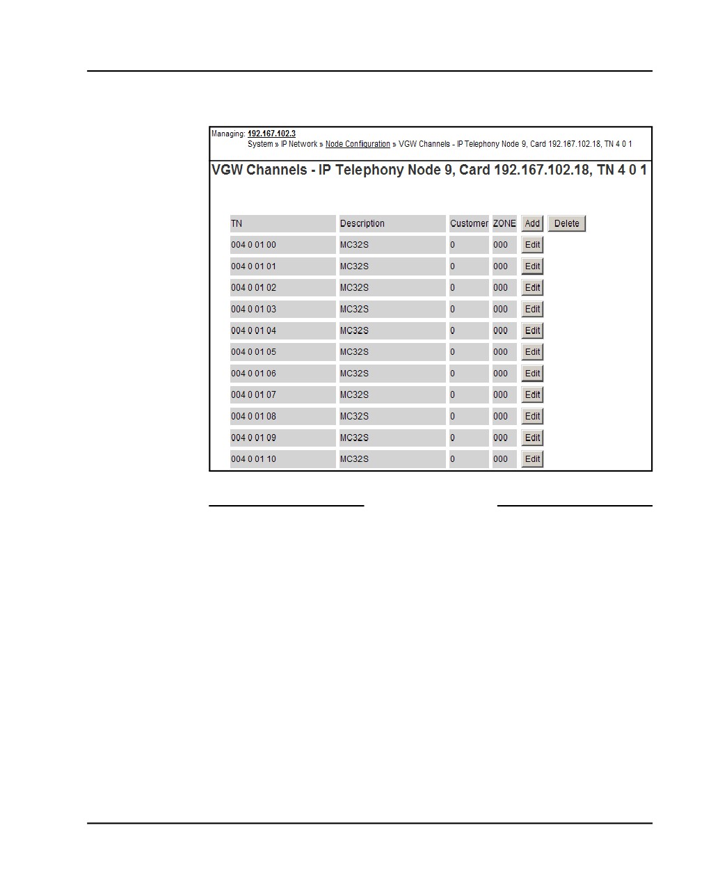
The VGW channels for this card are displayed. See Figure 132 on
page 325.
Note: If you receive an error that a pad category table does not exist for
this customer, go back to your DTI configuration step, (see “Basic system
telephony configuration” on page 457) and create a default DTI Data
Block (DDB), and then perform this procedure again.
NN43041-310
Standard 01.11
October 2008
Installing and configuring a Voice Gateway Media Card Page 325 of 466
Figure 132
VGW channels list
End of Procedure
Configuring voice gateway channels using LD 14
The voice gateway channels are also called “DSP channels” or the card’s
“physical TNs.” Follow Procedure 69 on page 326 to configure the voice
gateway channels using LD 14.
Note: The voice gateway channels can also be configured using Element
Manager. To configure the voice gateway channels using Element
Manager, follow Procedure 68 on page 323.
Communication Server 1000E Installation and Commissioning

Page 326 of 466
Installing and configuring a Voice Gateway Media Card
Procedure 69
Configuring voice gateway channels using LD 14
1
Log in to the CS 1000E.
a. Enter the command:
LOGI
System response:
PASS?
b. Enter the default password:
0000
2
Access LD 14. Enter the command:
LD 14
3
Enter responses shown in Table 43.
Table 43
LD 14 - Configure physical TNs (Part 1 of 2)
Prompt
Response
Description
REQ
NEW 24
Create 24 voice Media Gateway channels on an ITG-P Line card.
Not supported on MG 1000E.
NEW 32
Create 32 voice Media Gateway channels on a Media Card.
TYPE
VGW
Voice Gateway.
TN
l s c u
TN of the first Voice Gateway Media Card unit.
See Table 44 on page 335 for TN assignments.
DES
aa
a
Description for gateway channels.
Identify the channels using the card’s TLAN IP address or MAC
address.
XTRK
MC32
Media Card 32-port
NN43041-310
Standard 01.11
October 2008

Installing and configuring a Voice Gateway Media Card Page 327 of 466
Table 43
LD 14 - Configure physical TNs (Part 2 of 2)
Prompt
Response
Description
MAXU
32
32 is the maximum number of voice Media Gateway channels on
the Media Card.
24
24 is the maximum number of voice Media Gateway channels on
the ITG-P Line card.
IPTN
YES
ITG Physical TN.
ZONE
0-255
Zone number to which the Voice Gateway Media Card Physical
TNs belong.
Verify that the zone exists in LD 117.
The ZONE prompt is not available when configuring VGW in an
MG 1000E. The VGWs are assigned the same zone as the
MG 1000E.
Note: If the Zone of an MG 1000E is changed, all VGW in the
MG 1000E must be removed and reconfigured to assume the
new Zone of the MG 1000E.
CUST
xx
The customer to which the IPTN resources are assigned.
Note: This means that for multi-customer CS 1000E systems,
each customer must have a dedicated IP Telephony node for
IP Phones.
4
Exit from LD 14. Enter the command:
****
End of Procedure
Saving configuration changes
Perform a datadump to save configuration changes. Complete the steps in
Procedure 88: "Performing a datadump using Element Manager" on
page 376.
Communication Server 1000E Installation and Commissioning
Page 328 of 466
Installing and configuring a Voice Gateway Media Card
Installing a CompactFlash
The Voice Gateway Media Card requires a CompactFlash card to operate.
The CompactFlash card contains the IP Line 3.1 software.
CAUTION WITH ESDS DEVICES
Wear an antistatic device to avoid damage to the Voice
Gateway Media Card.
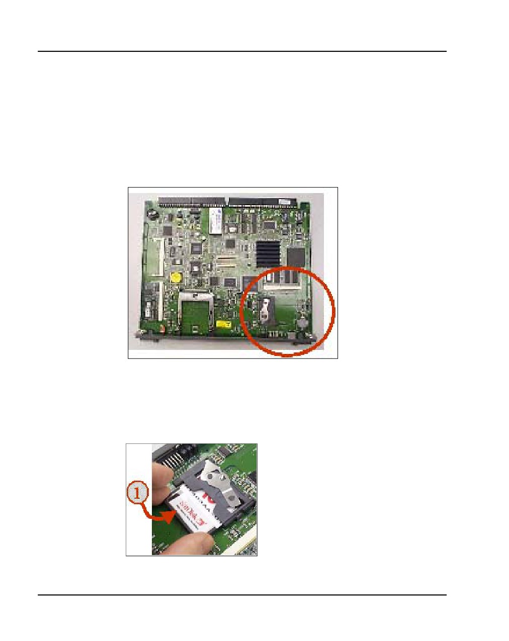
The Voice Gateway Media Card package includes the following:
•
Media Card
•
CompactFlash card and Retaining Pin (nylon pillar)
•
Shielded 50-pin to Serial/ELAN/TLAN adapter
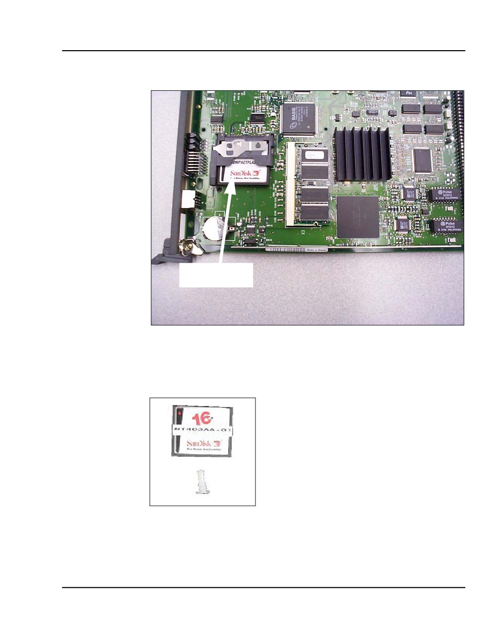
The CompactFlash card must be installed on the Voice Gateway Media Card
prior to installing the Voice Gateway Media Card in the system. Figure 133
on page 329 shows the CompactFlash card location on the Voice Gateway
Media Card.
NN43041-310
Standard 01.11
October 2008
Installing and configuring a Voice Gateway Media Card Page 329 of 466
Figure 133
CompactFlash card location
CompactFlash
card
Figure 134 shows the CompactFlash card and Retaining Pin.
Figure 134
CompactFlash card and Retaining Pin
Communication Server 1000E Installation and Commissioning
Page 330 of 466
Installing and configuring a Voice Gateway Media Card
Procedure 70
Installing the CompactFlash
1
Remove the Media Card, CompactFlash card, and Retaining Pin from the
packaging.
2
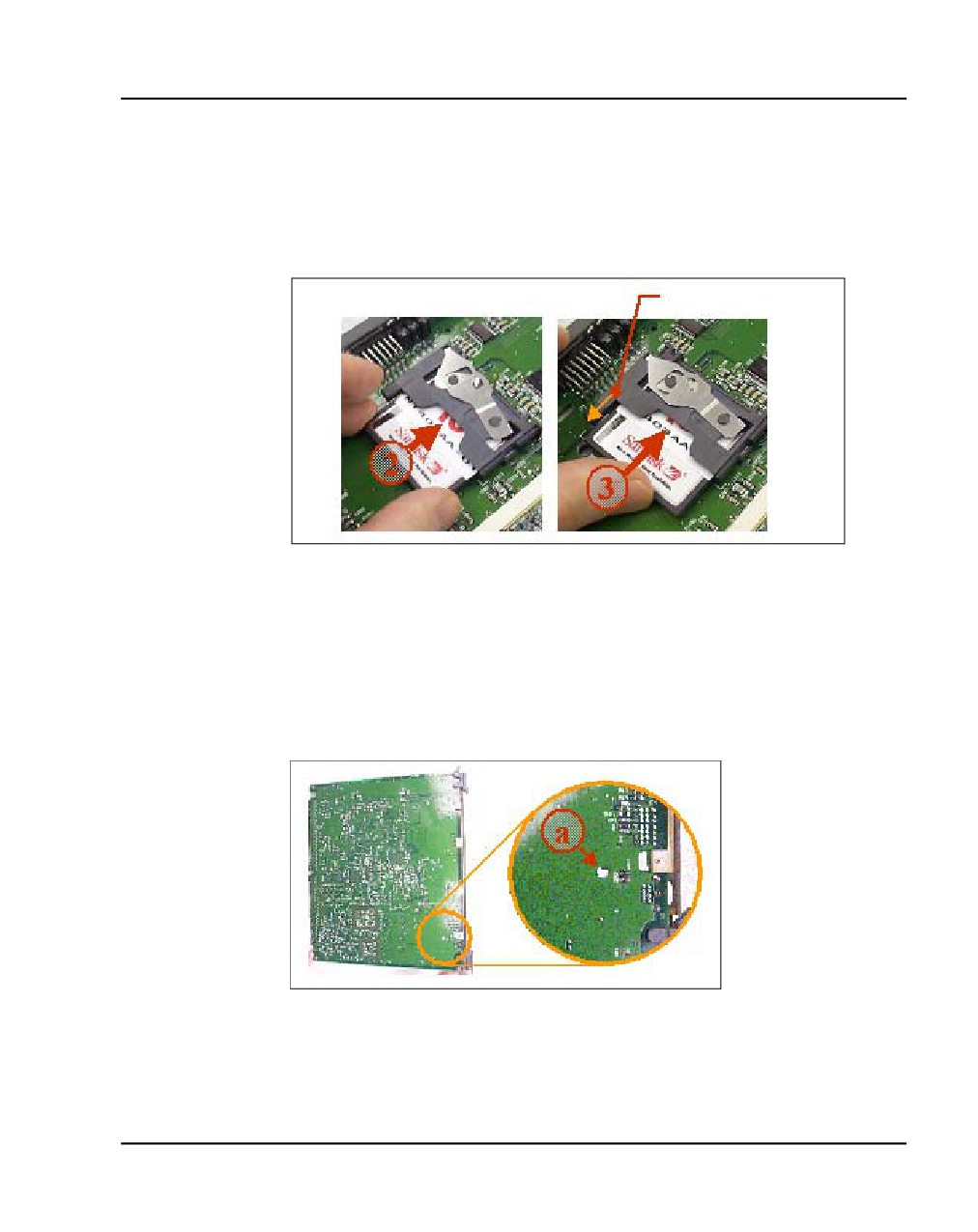
Locate the CompactFlash socket in the lower left-hand corner of the Voice
Gateway Media Card (see Figure 135).
Figure 135
CompactFlash socket on Voice Gateway Media Card
3
Position the CompactFlash card with the label facing up and contact pins
toward the socket, as shown in Figure 136.
Figure 136
Position the CompactFlash in socket
NN43041-310
Standard 01.11
October 2008
Installing and configuring a Voice Gateway Media Card Page 331 of 466
4
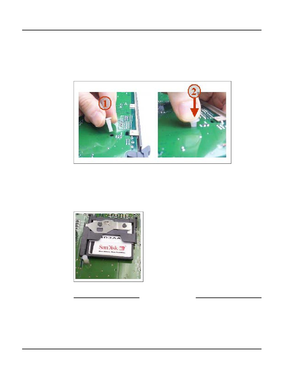
Insert the CompactFlash card in the socket.
Press firmly until it is fully seated and the Eject button extends (see
Figure 137).
Figure 137
Insert CompactFlash to extend Eject button
Eject button
5
Turn the Voice Gateway Media Card over to view the back of the card.
Identify the hole for the Retaining Pin. The hole (labeled a in Figure 138)
is located approximately 1 inch (2.5 cm) above the lower lock latch and
1 inch (2.5 cm) from the card’s faceplate.
Figure 138
Retaining Pin hole
6
Insert the Retaining Pin in this hole (labeled 1 in Figure 139).
Communication Server 1000E Installation and Commissioning
Page 332 of 466
Installing and configuring a Voice Gateway Media Card
Press the Retaining Pin into the hole until the pin clicks as it locks into
position (labeled 2 in Figure 139). The underside of the head of the
Retaining Pin should be flat against the card.
Figure 139
Inserting the Retaining Pin
7
Turn the card over to view the front of the card. Ensure the Retaining Pin
is in place, as shown Figure 140 on page 332.
Figure 140
Retaining Pin fully inserted
End of Procedure
NN43041-310
Standard 01.11
October 2008
Installing and configuring a Voice Gateway Media Card Page 333 of 466
Installing a card in a Media Gateway
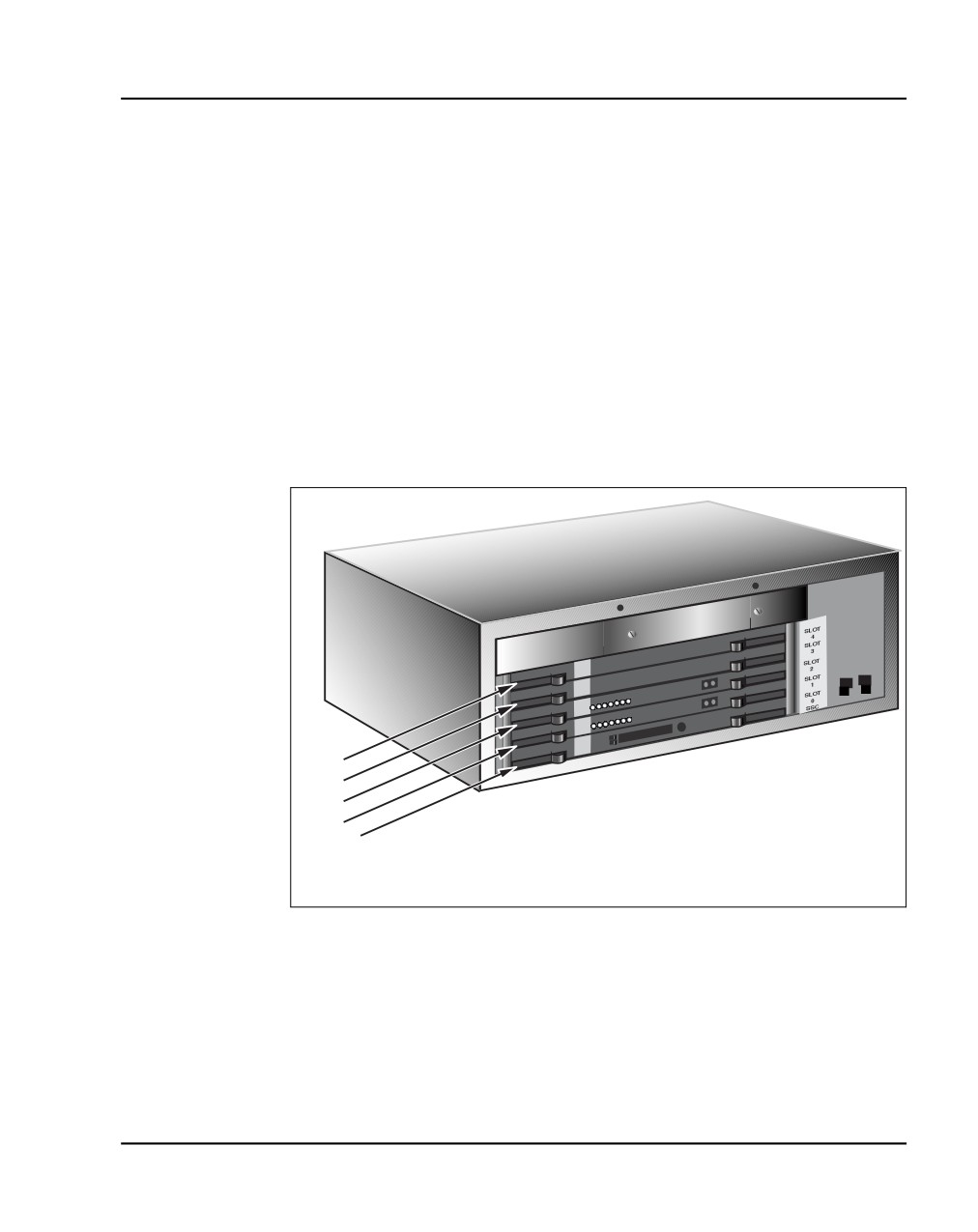
A Voice Gateway Media Card can be installed in a Media Gateway or a
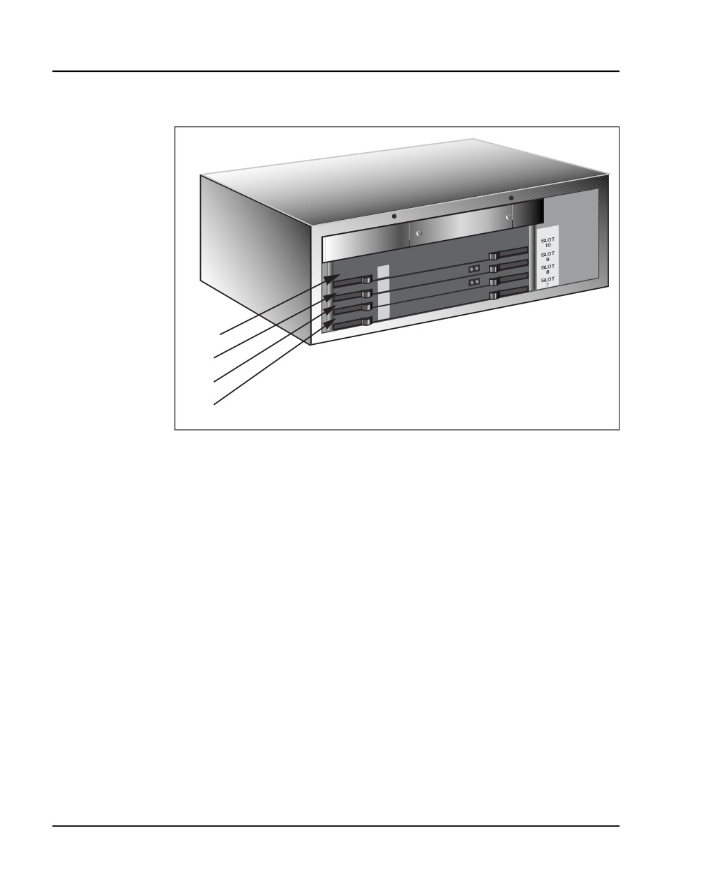
Media Gateway Expander slot. See Figure 141 on page 333 and Figure 142
on page 334 to make sure that you insert the Voice Gateway Media Card in
the correct slot.
Note: See your installation worksheet, provided by your Planning and
Engineering group for the correct slot for the Voice Gateway Media
Cards.
Figure 141 shows the circuit card assignments in the Media Gateway.
Figure 141
Media Gateway card slot location
Slot 4
Slot 3
Slot 2
Slot 1
Slot 0 - SSC
553-CSE9025
Figure 142 on page 334 shows the circuit card assignments in the Media
Gateway Expander.
Communication Server 1000E Installation and Commissioning
Page 334 of 466
Installing and configuring a Voice Gateway Media Card
Figure 142
Media Gateway Expander card slot location
Slot 10
Slot 9
Slot 8
Slot 7
553-CSE9032
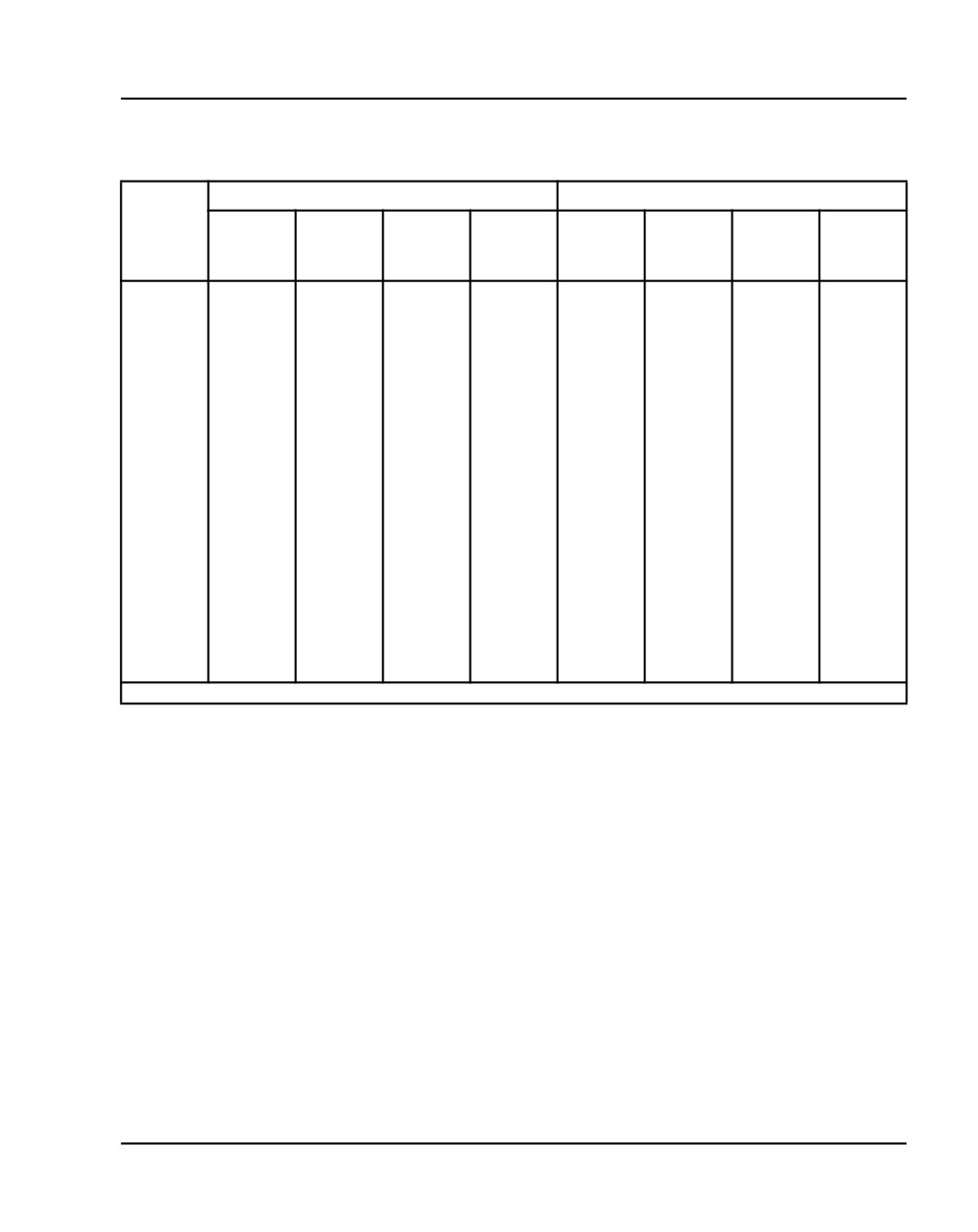
Table 44 on page 335 shows the TN assignments for the MG 1000E.
Communication Server 1000 Release 5.0 supports up to 30 MG 1000E.
NN43041-310
Standard 01.11
October 2008
Installing and configuring a Voice Gateway Media Card Page 335 of 466
Table 44
TN assignments for MG 1000E
MG 1000E
MG 1000E Expander
Slots
1
2
3
4
7
8
9
10
TN
l s c
l s c
l s c
l s c
l s c
l s c
l s c
l s c
MG 1000E
1
000 0 01
000 0 02
000 0 03
000 0 04
000 0 07
000 0 08
000 0 09
000 0 10
2
000 1 01
000 1 02
000 1 03
000 1 04
000 1 07
000 1 08
000 1 09
000 1 10
3
004 0 01
004 0 02
004 0 03
004 0 04
004 0 07
004 0 08
004 0 09
004 0 10
4
004 1 01
004 1 02
004 1 03
004 1 04
004 1 07
004 1 08
004 1 09
004 1 10
5
008 0 01
008 0 02
008 0 03
008 0 04
008 0 07
008 0 08
008 0 09
008 0 10
6
008 1 01
008 1 02
008 1 03
008 1 04
008 1 07
008 1 08
008 1 09
008 1 10
7
012 0 01
012 0 02
012 0 03
012 0 04
012 0 07
012 0 08
012 0 09
012 0 10
8
012 1 01
012 1 02
012 1 03
012 1 04
012 1 07
012 1 08
012 1 09
012 1 10
9
016 0 01
016 0 02
016 0 03
016 0 04
016 0 07
016 0 08
016 0 09
016 0 10
10
016 1 01
016 1 02
016 1 03
016 1 04
016 1 07
016 1 08
016 1 09
016 1 10
11
020 0 01
020 0 02
020 0 03
020 0 04
020 0 07
020 0 08
020 0 09
020 0 10
12
020 1 01
020 1 02
020 1 03
020 1 04
020 1 07
020 1 08
020 1 09
020 1 10
13
024 0 01
024 0 02
024 0 03
024 0 04
024 0 07
024 0 08
024 0 09
024 0 10
14
024 1 01
024 1 02
024 1 03
024 1 04
024 1 07
024 1 08
024 1 09
024 1 10
127
252 0 01
252 0 02
252 0 03
252 0 04
252 0 07
252 0 08
252 0 09
252 0 10
128
252 1 01
252 1 02
252 1 03
252 1 04
252 1 07
252 1 08
252 1 09
252 1 10
Note:
The bottom most card slot in the Media Gateway is reserved for the SSC card.
Procedure 71
Installing a Voice Gateway Media Card in a card slot
The ELAN subnet and TLAN subnet should already be connected on the back
of the Media Gateway. If not, refer back to “Installing and connecting
CS 1000E hardware” on page 101.
Optionally, you can connect a maintenance terminal to the maintenance port
on the Voice Gateway Media Card, to see the Voice Gateway Media Card’s
boot messages or to perform maintenance on it. See “Installing and
connecting CS 1000E hardware” on page 101 for more detail.
1
Install the Voice Gateway Media Card into the card slot.
a. Pull the top and bottom locking devices away from the card faceplate.
b. Insert the Voice Gateway Media Card into the card guides and gently
push it until it makes contact with the backplane connector.
Communication Server 1000E Installation and Commissioning
Page 336 of 466
Installing and configuring a Voice Gateway Media Card
c. Hook the locking devices.
Note: The Voice Gateway Media Card boots automatically. If the Voice
Gateway Media Card is a Follower, then it retrieves the node
configuration files from the IP telephony node Leader. If it is a Leader,
then you must configure it. See IP Line: Description, Installation, and
Operation (NN43100-500) for a detailed configuration procedure.
2
Observe the Voice Gateway Media Card faceplate display.
The red LED remains lit until the card is configured and enabled, at which
point it turns off. When the card has finished booting, the display is either
“Fxxx” or “Lxxx” (where xxx is the number of telephones registered to the
card), indicating that the card is a Follower or Leader.
3
If required, you can now perform maintenance on the card using Element
Manager, or through the card’s maintenance port if you connected a
maintenance terminal to it. See IP Line: Description, Installation, and
Operation (NN43100-500) for detailed maintenance procedures.
End of Procedure
Verifying a card
Verifying a card involves:
•
Procedure 72: "Displaying the Voice Gateway Media Card status" on
page 336
•
Procedure 73: "Displaying the Voice Gateway status
for all voice gateway channels" on page 338
•
Procedure 74: "Displaying the status of Voice Gateway Media Card
units" on page 341
•
Procedure 75: "Displaying the status of one unit on a Voice Gateway
Media Card" on page 344
Procedure 72
Displaying the Voice Gateway Media Card status
1
In Element Manager, select IP Network> Nodes: Servers, Media Cards
> Maintenance and Reports from the navigator.
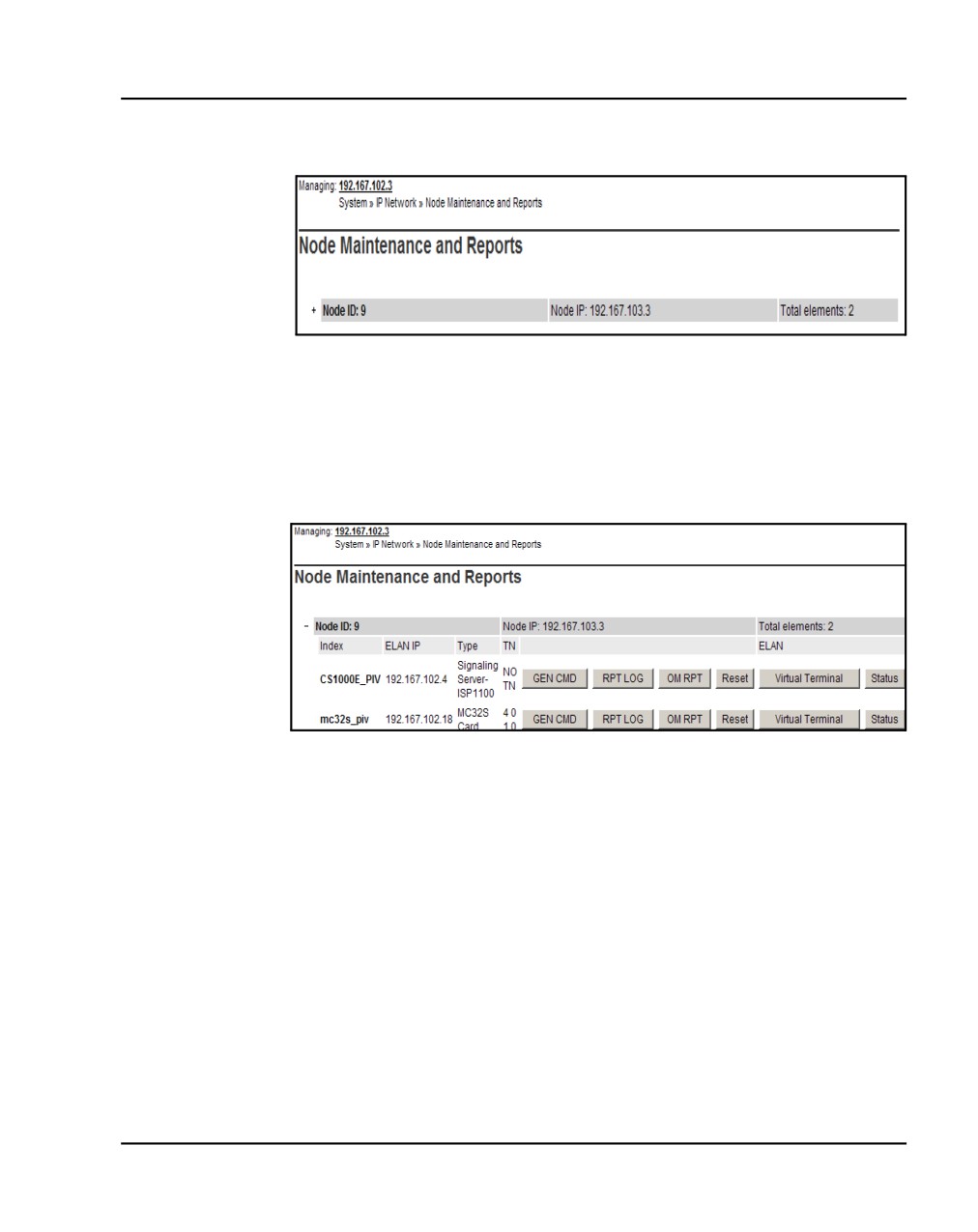
The Node Maintenance and Reports web page opens, as shown in
Figure 143.
NN43041-310
Standard 01.11
October 2008
Installing and configuring a Voice Gateway Media Card Page 337 of 466
Figure 143
Node Maintenance and Reports web page
2
Open the desired node by clicking on the + next to the Node ID.
This displays the Signaling Servers and Voice Gateway Media Cards
belonging to the node, as shown in Figure 144 on page 337.
Figure 144
Node Maintenance and Reports - expanded node
3
Click Status for the desired Voice Gateway Media Card.
The output from this command is displayed in the window pane
(result box).
The output can be one of the following:
xx.xxx.xxx.xxx : Disabled
xx.xxx.xxx.xxx : Enabled
xx.xxx.xxx.xxx : Unequipped
Communication Server 1000E Installation and Commissioning
Page 338 of 466
Installing and configuring a Voice Gateway Media Card
Where xx.xxx.xxx.xxx is the ELAN IP address of the Voice Gateway
Media Card and the meaning of the status is:
•
Disabled - The card is configured but out-of-service.
•
Enabled - The card is configured and operational.
•
Unequipped - The card is not configured in the Call Server.
End of Procedure
Procedure 73
Displaying the Voice Gateway status for all voice gateway channels
1
In Element Manager, select IP Network > Nodes: Servers, Media Cards
> Maintenance and Reports from the navigator.
The Node Maintenance and Reports web page opens, as shown in
Figure 143 on page 337.
2
Open the desired node by clicking on the + next to the Node ID.
This displays the Signaling Servers and Voice Gateway Media Cards
belonging to the node, as shown in Figure 144 on page 337.
3
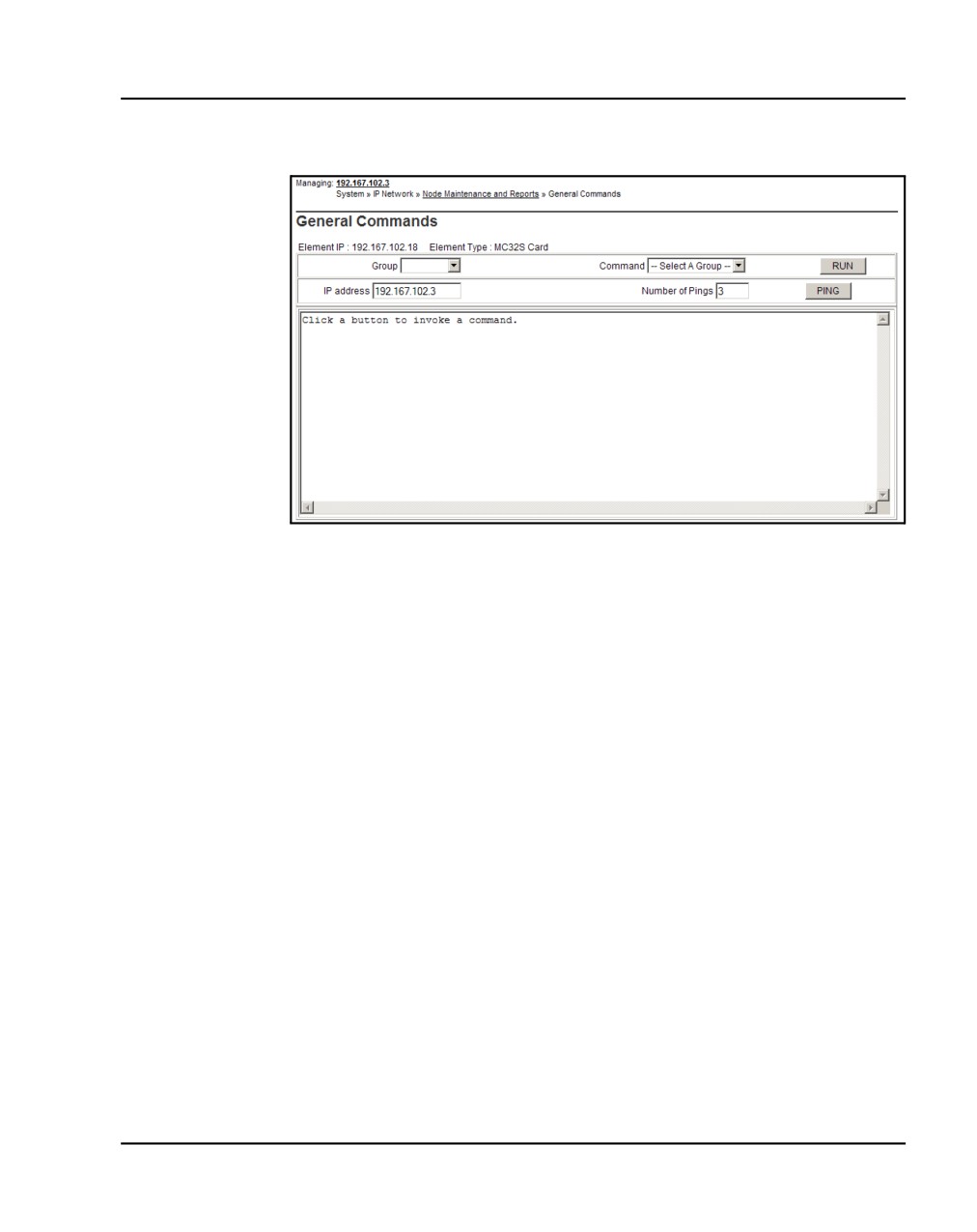
Click GEN CMD for the desired Voice Gateway Media Card.
The General Commands web page opens, as shown in Figure 145.
NN43041-310
Standard 01.11
October 2008
Installing and configuring a Voice Gateway Media Card Page 339 of 466
Figure 145
General Commands
4
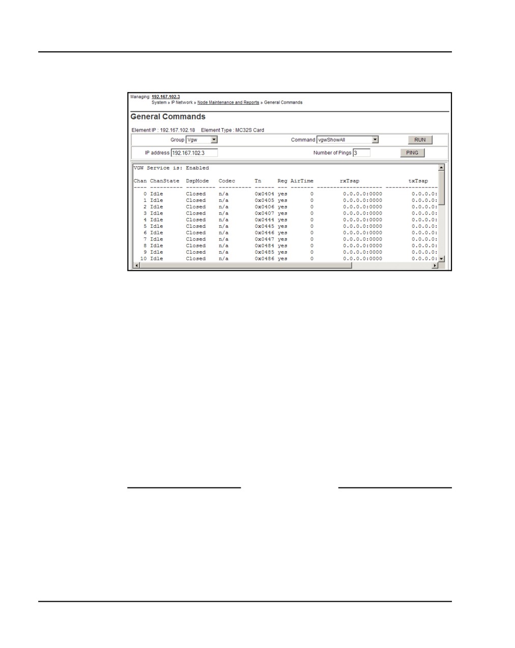
From the Group drop-down list, select Vgw.
5
From the Command drop-down list, select vgwShowAll.
6
Click RUN.
Figure 146 on page 340 shows the General Commands web page with
the output from the vgwShowAll command. The output shows
information about all the voice gateway channels.
Communication Server 1000E Installation and Commissioning
Page 340 of 466
Installing and configuring a Voice Gateway Media Card
Figure 146
vgwShowAll result
The following information is provided for each VGW channel:
•
Chan - Channel number
•
ChanState - State of channel (Idle/Busy/Disabled/Unequipped)
•
DspMode - Mode DSP is in (Voice/Closed)
•
Codec - Codec frame-size used for the call
•
Tn - Channel's physical TN in packed format
•
Reg - Status of channel's gateway registration
•
Air Time - Duration of audio stream connection in seconds. Zero
when the audio stream is closed.
•
txTsap - IP address and port the Voice Gateway Media Card is using
to send RTP packets.
End of Procedure
NN43041-310
Standard 01.11
October 2008
Installing and configuring a Voice Gateway Media Card Page 341 of 466
Procedure 74
Displaying the status of Voice Gateway Media Card units
1
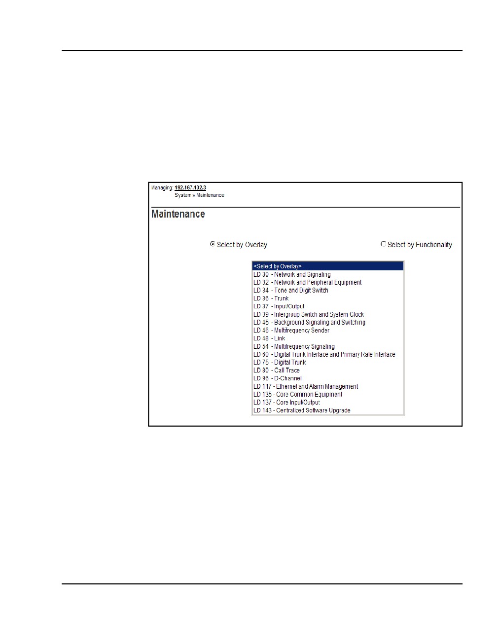
Select System > Maintenance from the navigator.
The Maintenance web page opens as shown in Figure 147. This page
allows you to perform maintenance using overlays or using a selected
functionality. The default is overlay, as shown in Figure 147.
Figure 147
Maintenance (by Overlay) web page
2
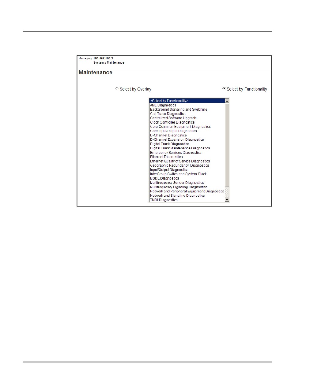
Select Select by Functionality.
The list in the web page changes to show a list of diagnostics you can use,
as shown in Figure 148 on page 342.
Communication Server 1000E Installation and Commissioning
Page 342 of 466
Installing and configuring a Voice Gateway Media Card
Figure 148
Maintenance (by functionality) web page
3
Select Network & Peripheral Equipment Diagnostics from the list in
Figure 148.
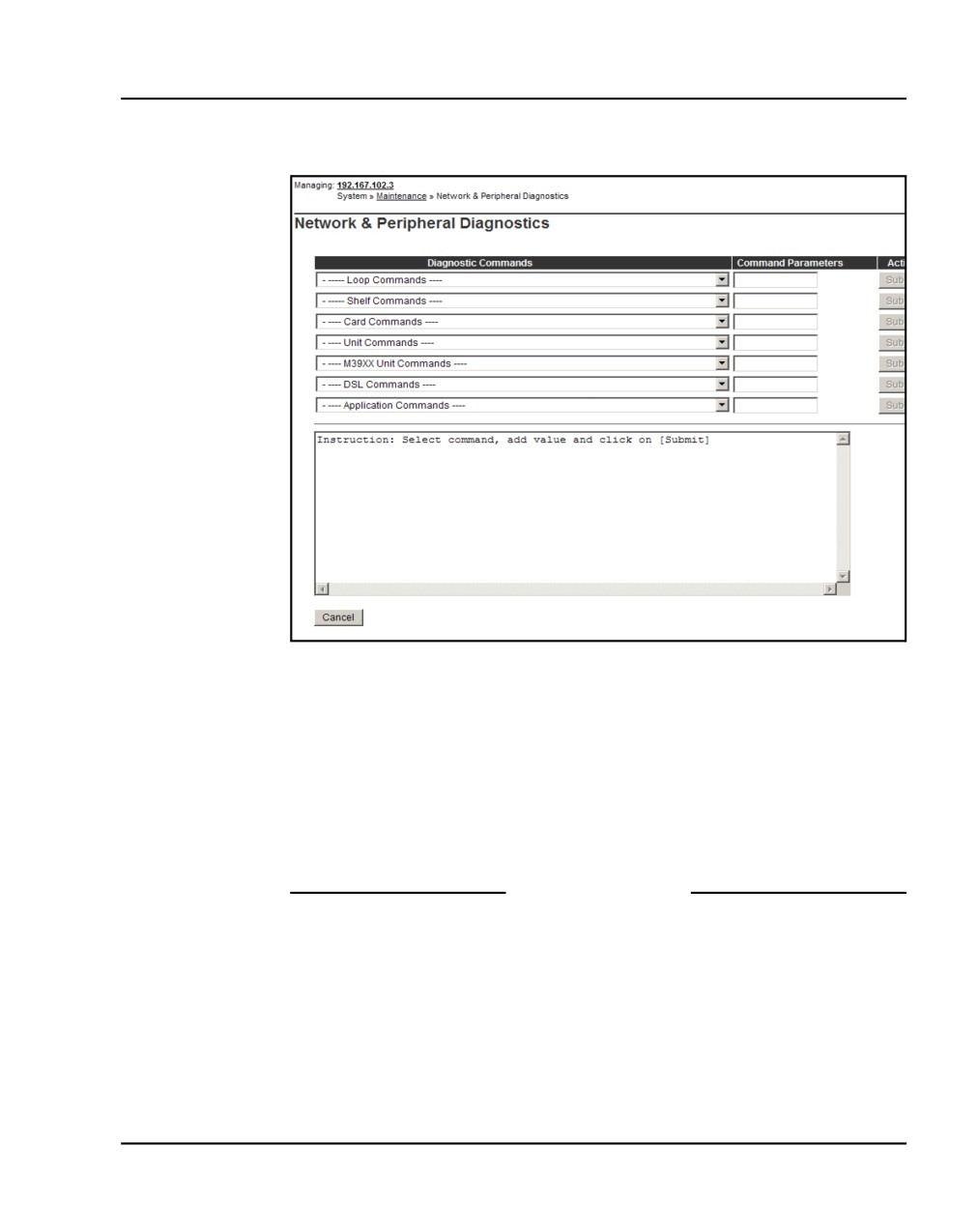
The Network and Peripheral Diagnostics web page opens, as shown in
Figure 149 on page 343.
NN43041-310
Standard 01.11
October 2008
Installing and configuring a Voice Gateway Media Card Page 343 of 466
Figure 149
Network & Peripheral Diagnostics web page
4
Choose the STAT — Get card status command from the Card
Commands drop-down list.
5
Enter the card number in the corresponding Command Parameter text
box.
6
Click Submit to the right of the text box.
The output from this command is shown in the text box in the lower half
of the web page.
End of Procedure
Communication Server 1000E Installation and Commissioning
Page 344 of 466
Installing and configuring a Voice Gateway Media Card
Procedure 75
Displaying the status of one unit on a Voice Gateway Media Card
1
Select System > Maintenance from the navigator.
The Maintenance web page opens as shown in Figure 147 on page 341.
This page allows you to perform maintenance using overlays or using a
selected functionality. The default is overlay, as shown in Figure 147.
2
Select Select by Functionality.
The list in the web page changes to show a list of diagnostics you can use,
as shown in Figure 148 on page 342.
3
Select Network & Peripheral Equipment Diagnostics from the list in
Figure 148 on page 342.
The Network and Peripheral Diagnostics web page opens, as shown in
Figure 149 on page 343.
4
Choose the STAT — Get unit status command from the Unit
Commands drop-down list.
5
Enter the card number and unit number in the corresponding Command
Parameter text box.
6
Click Submit to the right of the text box.
The output from this command is shown in the text box in the lower half
of the web page.
End of Procedure
Disabling a card
Follow Procedure 76 to disable a Voice Gateway Media Card using
Element Manager.
Procedure 76
Disabling a Voice Gateway Media Card using Element Manager
1
Select System > Maintenance from the navigator.
The Maintenance web page opens as shown in Figure 147 on page 341.
This page allows you to perform maintenance using overlays or using a
selected functionality. The default is overlay, as shown in Figure 147.
2
Select Select by Functionality.
NN43041-310
Standard 01.11
October 2008
Installing and configuring a Voice Gateway Media Card Page 345 of 466
The list in the web page changes to show a list of diagnostics you can use,
as shown in Figure 148 on page 342.
3
Select Network & Peripheral Equipment Diagnostics from the list in
Figure 148 on page 342.
The Network and Peripheral Diagnostics web page opens, as shown in
Figure 149 on page 343.
4
Select the DISC - Disable Peripheral card command from the Card
Commands drop-down list.
5
Enter the card number in the corresponding Command Parameter text
box.
6
Click Submit to the right of the text box.
The output from this command is shown in the text box in the lower half
of the web page.
End of Procedure
Note: For graceful disabling of the voice gateway channels refer to
“Graceful Disable” in IP Line: Description, Installation, and Operation
(NN43100-500).
Disabling a card unit
Follow Procedure 77 to disable a Voice Gateway Media Card unit in
Element Manager.
Procedure 77
Disabling a Voice Gateway Media Card unit using Element Manager
1
Select System > Maintenance from the navigator.
The Maintenance web page opens as shown in Figure 147 on page 341.
This page allows you to perform maintenance using overlays or using a
selected functionality. The default is overlay, as shown in Figure 147.
2
Select Select by Functionality.
The list in the web page changes to show a list of diagnostics you can use,
as shown in Figure 148 on page 342.
3
Select Network & Peripheral Equipment Diagnostics from the list in
Figure 148 on page 342.
Communication Server 1000E Installation and Commissioning
Page 346 of 466
Installing and configuring a Voice Gateway Media Card
The Network and Peripheral Diagnostics web page opens, as shown in
Figure 149 on page 343.
4
Select the DISU - Disable unit command from the Unit Commands
drop-down list.
5
Enter the card number and unit number in the corresponding Command
Parameter text box.
6
Click Submit to the right of the text box.
The output from this command is shown in the text box in the lower half
of the web page.
End of Procedure
Enabling a card
Follow Procedure 78 to enable a Voice Gateway Media Card using
Element Manager.
Procedure 78
Enabling a Voice Gateway Media Card using Element Manager
1
Select System > Maintenance from the navigator.
The Maintenance web page opens as shown in Figure 147 on page 341.
This page allows you to perform maintenance using overlays or using a
selected functionality. The default is overlay, as shown in Figure 147.
2
Select Select by Functionality.
The list in the web page changes to show a list of diagnostics you can use,
as shown in Figure 148 on page 342.
3
Select Network & Peripheral Equipment Diagnostics from the list in
Figure 148 on page 342.
The Network and Peripheral Diagnostics web page opens, as shown in
Figure 149 on page 343.
4
Select the ENLC - Enable and reset card command from the Card
Commands drop-down list.
5
Enter the card number in the corresponding Command Parameter text
box.
6
Click Submit to the right of the text box.
NN43041-310
Standard 01.11
October 2008
Installing and configuring a Voice Gateway Media Card Page 347 of 466
The output from this command is shown in the text box in the lower half
of the web page.
End of Procedure
Enabling a card unit
Follow Procedure 79 to enable a Voice Gateway Media Card unit using
Element Manager.
Procedure 79
Enabling a Voice Gateway Media Card unit using Element Manager
1
Select System > Maintenance from the navigator.
The Maintenance web page opens as shown in Figure 147 on page 341.
This page allows you to perform maintenance using overlays or using a
selected functionality. The default is overlay, as shown in Figure 147.
2
Select Select by Functionality.
The list in the web page changes to show a list of diagnostics you can use,
as shown in Figure 148 on page 342.
3
Select Network & Peripheral Equipment Diagnostics from the list in
Figure 148 on page 342.
The Network and Peripheral Diagnostics web page opens, as shown in
Figure 149 on page 343.
4
Select the ENLU - Enable unit command from the Unit Commands
drop-down list.
5
Enter the card number and unit number in the corresponding Command
Parameter text box.
6
Click Submit to the right of the text box.
The output from this command is shown in the text box in the lower half
of the web page.
End of Procedure
Communication Server 1000E Installation and Commissioning
Page 348 of 466
Installing and configuring a Voice Gateway Media Card
Verifying functionality
You can now use the Voice Gateway Media Card to transcode voice data
between IP and TDM. To test the voice gateway channels (DSPs), perform a
variety of analog or digital calls to IP Phones and vice-versa.
Note: You require analog or digital telephones or trunks to perform this
test.
Upgrading loadware
Refer to Communication Server 1000E: Upgrade Procedures
(NN43041-458) to check for the latest Voice Gateway Media Card loadware
version and how to upgrade to the latest Voice Gateway Media Card
loadware.
NN43041-310
Standard 01.11
October 2008
360
Page 349 of 466
Installing the Main Distribution Frame
Contents
This section contains information on the following topics:
Introduction
349
Terminal block requirements
350
Installing a BIX cross-connect terminal
350
Installing a Krone Test Jack Frame for the UK
352
Connecting the cables to the Media Gateways
356
Introduction
This chapter describes how to install and connect a CS 1000E system using
the BIX, or Krone Test Jack Frame (UK) cross-connect terminals.
This chapter contains the following procedures:
1
Procedure 80: “Installing a BIX cross-connect terminal” on page 350.
2
Procedure 81: “Installing the Krone Test Jack Frame (UK)” on page 354.
3
Procedure 82: “Connecting the cables to the Media Gateways” on
page 356.
Note: The use of the BIX system is not mandatory; however, it is the
recommended option.
Communication Server 1000E Installation and Commissioning
Page 350 of 466
Installing the Main Distribution Frame
Terminal block requirements
The cross-connect terminal requires enough connecting blocks to terminate
up to four 25 pair cables for each Media Gateway and each Media Gateway
Expander. When Ethernet connections are used instead of traditional cabling,
the Media Card Input/Output adapter is used:
•
For the 1.5 Mbit DTI/PRI circuit card NTRB21, use the NTBK04 cable.
•
For the 2.0 Mbit DTI circuit card NTAK10, 2.0 Mbit PRI circuit card
NTAK79, and 2.0 Mbit PRI circuit card NTBK50, use the NTBK05
cable.
•
Each IPE card slot equipped with a Line or Trunk card requires a 25-pair
cable from the host Media Gateway or Media Gateway Expander.
•
Four conductors for the AUX cable from the Media Gateway.
•
One 25-pair cable from each Power Fail Transfer Unit (PFTU) QUA6.
•
Wiring from telephones and trunks
DANGER
Do not install telephone wiring during a lightning storm.
Never touch uninsulated telephone wiring, unless the
line is disconnected at the network interface.
Installing a BIX cross-connect terminal
Procedure 80 describes how to install a BIX cross-connect terminal. For
detailed information, refer to the Nordex BIX documentation.
Procedure 80
Installing a BIX cross-connect terminal
1
Refer to the equipment layout plan to determine where to place the
cross-connect terminal.
2
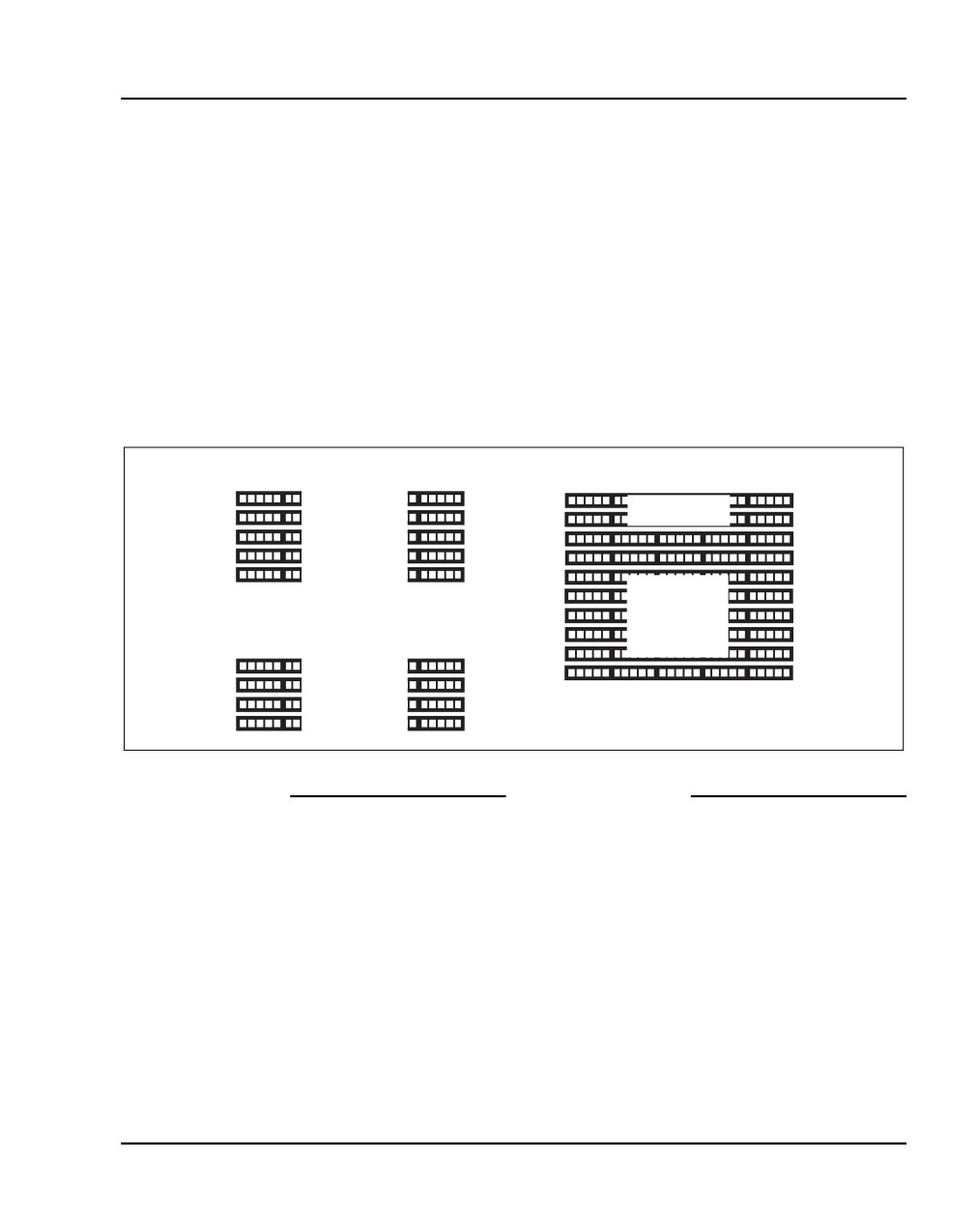
Lay out the terminal blocks as shown in Figure 150 on page 351.
NN43041-310
Standard 01.11
October 2008
Installing the Main Distribution Frame
Page 351 of 466
3
Attach labels on the cross-connect terminal to indicate the terminal blocks
assigned to the following:
•
25-pair cables from the system
•
AUX wiring
•
PFTUs
•
Telephones and consoles
•
Trunks
•
Miscellaneous equipment
Figure 150
Typical BIX cross-connect terminal layout
Media Gateway
Cable Card 1
AUX cable
Cable Card 2
PFTU
Cable Card 3
Cable Card 4
Telephones
Trunks
and
Media Gateway Expansion
Miscellaneous
Cable Card 7
Cable Card 8
Cable Card 9
Cable Card 10
553-CSE9026A
End of Procedure
Communication Server 1000E Installation and Commissioning
Page 352 of 466
Installing the Main Distribution Frame
Installing a Krone Test Jack Frame for the UK
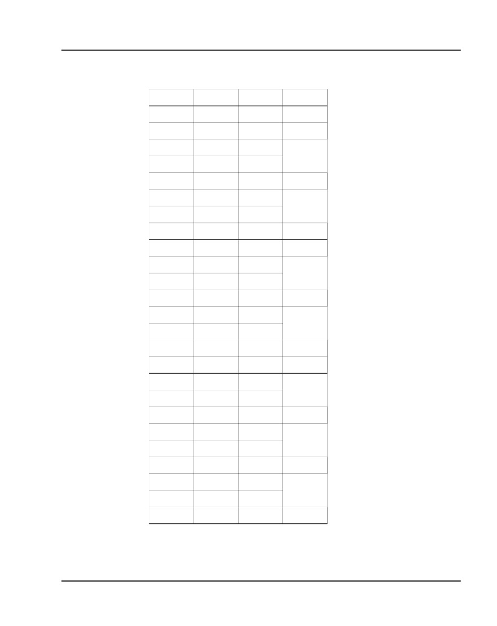
The Krone Test Jack Frame provides terminating strips that hold ten pairs of
cable. Generally, only eight of ten pairs are used. As a result, one 25-pair
cable requires three terminating strips (8 pairs/strip x 3 strips = 24 pairs).
Figure 151 on page 353 shows how one 25-pair cable is divided among three
terminating strips on the Krone Test Jack Frame.
NN43041-310
Standard 01.11
October 2008
Installing the Main Distribution Frame
Page 353 of 466
Figure 151
25-pair cable on three Krone strips
Pair
Pin Number
Wire Colour
Krone Strip
1T
26
W-BL
1R
1
BL-W
2T
27
W-O
2R
2
O-W
3T
28
W-G
3R
3
G-W
4T
29
W-BR
1
4R
4
BR-W
5T
30
W-S
5R
5
S-W
6T
31
R-BL
6R
6
BL-R
7T
32
R-O
7R
7
O-R
8T
33
R-G
8R
8
G-R
9T
34
R-BR
9R
9
BR-R
10T
35
R-S
10R
10
S-R
11T
36
BK-BL
11R
11
BL-BK
12T
37
BK-O
2
12R
12
O-BK
13T
38
BK-G
13R
13
G-BK
14T
39
BK-BR
14R
14
BR-BK
15T
40
BK-S
15R
15
S-BK
16T
41
Y-BL
16R
16
BL-Y
17T
42
Y-O
17R
17
O-Y
18T
43
Y-G
18R
18
G-Y
19T
44
Y-BR
19R
19
BR-Y
20T
45
Y-S
20R
20
S-Y
21T
46
V-BL
3
21R
21
BL-V
22T
47
V-O
22R
22
O-V
23T
48
V-G
23R
23
G-V
24T
49
V-BR
24R
24
BR-V
25T
50
V-S
25R
25
S-V
553-CSE0019
Communication Server 1000E Installation and Commissioning
Page 354 of 466
Installing the Main Distribution Frame
Procedure 81 describes how to install the Krone Test Jack Frame for the UK.
For detailed information, refer to the Krone documentation.
Procedure 81
Installing the Krone Test Jack Frame (UK)
1
Refer to the equipment layout plan to determine where to place the
cross-connect terminal.
2
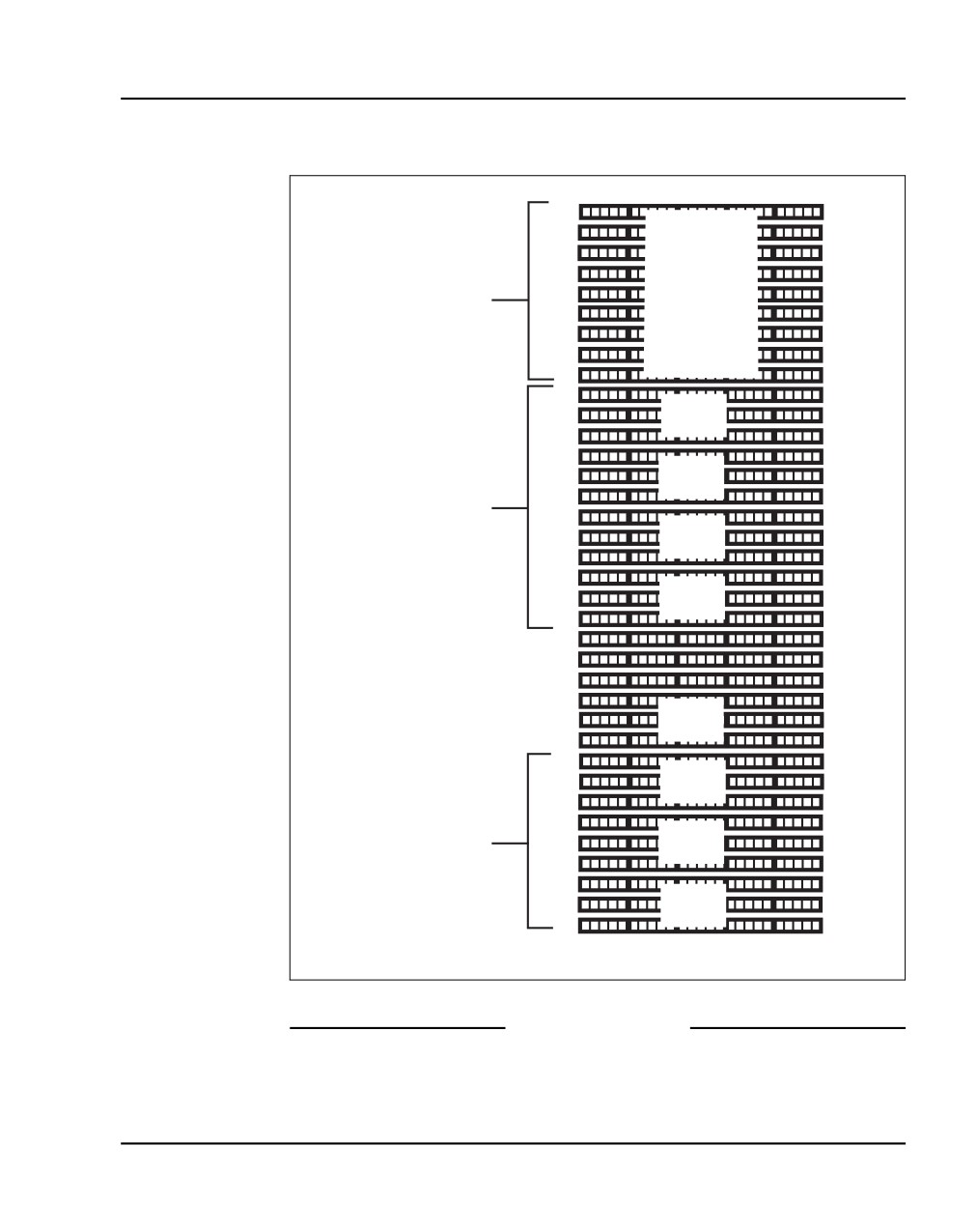
Lay out the terminal blocks as shown in Figure 152 on page 355.
3
Attach labels on the cross-connect terminal to indicate the terminal blocks
assigned to the following:
•
Analog Line cards
•
DC15/AC15/RAN/PAG cards
•
Data Access cards
•
AUX wiring
•
Power Fail Transfer Units
•
Digital Line cards
•
Telephones
•
Exchange Line Trunk cards
•
Direct Dialing Inward trunk cards
•
Miscellaneous equipment
NN43041-310
Standard 01.11
October 2008
Installing the Main Distribution Frame
Page 355 of 466
Figure 152
Typical Krone cross-connect terminal layout (UK)
Pair
Pair
Spare
17
24
PFTU
9
16
termination
1
8
Other
1
AUX cable
6
equipment
Grounding block
17
24
9
16
1
8
17
24
9
Card 10
16
1
8
17
24
9
Card 9
16
1
8
Media Gateway
Expansion
17
24
9
Card 8
16
1
8
17
24
9
Card 7
16
1
8
9
16
9
16
1
8
1
8
9
Card 4
16
1
8
17
24
9
Card 3
16
1
8
17
24
Media Gateway
9
Card 2
16
1
8
17
24
9
Card 1
16
1
8
553-CSE9033
End of Procedure
Communication Server 1000E Installation and Commissioning
Page 356 of 466
Installing the Main Distribution Frame
Connecting the cables to the Media Gateways
DANGER
Always use caution when installing or modifying
telephone lines. Do not install telephone wiring during a
lightning storm. Never touch uninsulated telephone
wiring unless the line is disconnected at the network
interface.
Each Media Gateway and each Media Gateway Expander requires up to four
25-pair cables. The CS 1000E requires an additional terminal block at the
cross-connect terminal to terminate the 9-pin conductor auxiliary cable for
the QUA6 Power Fail Transfer Unit (PFTU).
WARNING
Do not use the NE-A25B cable with the NTRB21,
NTAK10, NTBK50, or NTAK79 circuit cards.
Procedure 82
Connecting the cables to the Media Gateways
1
Loosen the velcro straps at each connector you plan to use.
2
Connect a 25-pair cable to each of the connectors that contains a line or
trunk card. Refer to the card slot assignment plan.
3
Tag both ends of each cable with the equipment and connector numbers.
See Figure 153 on page 357 and Figure 154 on page 357.
NN43041-310
Standard 01.11
October 2008

Installing the Main Distribution Frame
Page 357 of 466
Figure 153
Cable connectors at the back of the Media Gateway
25-pair
connectors
Figure 154
Cable connectors at the back of the Media Gateway Expander
25-pair
connectors
Communication Server 1000E Installation and Commissioning
Page 358 of 466
Installing the Main Distribution Frame
4
Tighten the velcro straps when you have connected each cable to the
system.
5
Terminate all the 25-pair cables installed at the cross-connect terminal.
6
Label all the cables at the cross-connect terminal blocks according to the
card slot assignment plan.
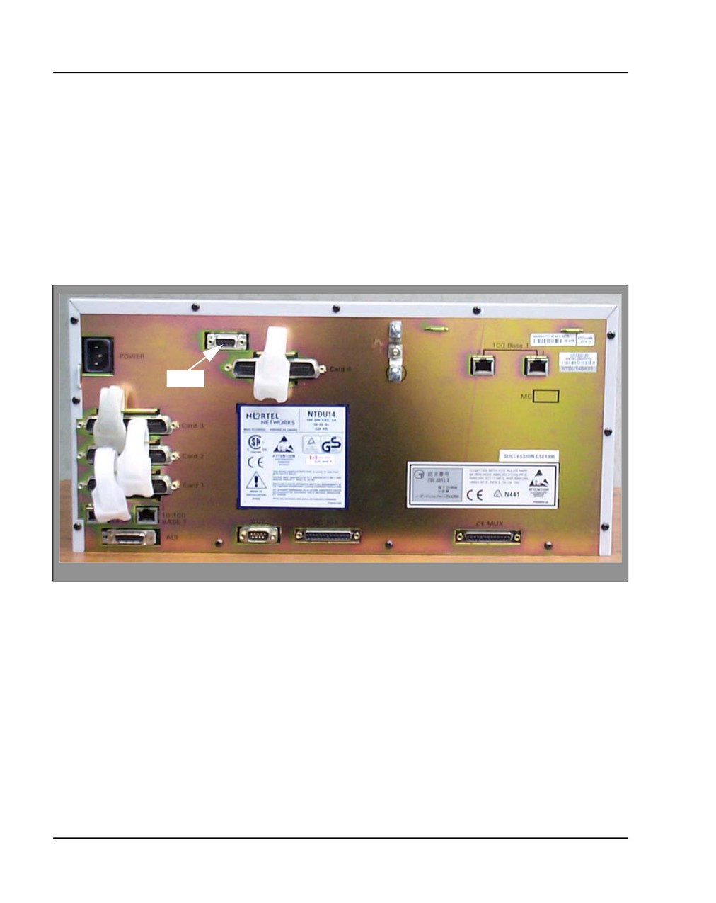
7
Connect the AUX cable in the upper 9-pin connector located on the top
left-hand side of the Media Gateway. See Figure 155 on page 358.
Figure 155
AUX cable connector
AUX
NN43041-310
Standard 01.11
October 2008

Installing the Main Distribution Frame
Page 359 of 466
8
When auxiliary power is required from the QUA6 PFTU, terminate the
AUX cable at the PFTU cross-connect terminal, according to Table 45.
Table 45
AUX cable termination information
Color
Wire number
Designation
Connection
W-BL
1
BRTN
to QUA6-J1 1R
BL-W
2
BRTN
to QUA6-J1 2R
O-W
3
-48V AUX
to QUA6-J1
(250mA)
25T, 25R
W-O
4
PFTS
to QUA6-J1 2T
G-W
5
Not used
Not used
W-G
6
Not used
Not used
End of Procedure
Communication Server 1000E Installation and Commissioning
Page 360 of 466
Installing the Main Distribution Frame
NN43041-310
Standard 01.11
October 2008
378
Page 361 of 466
Configuring an IP telephony node
Contents
This section contains information on the following topics:
Introduction
361
Before you begin
362
Configuring MS Internet Explorer
363
Logging in to Element Manager
366
Importing preconfigured IP telephony files
368
Reviewing and submitting IP telephony node configuration files
370
Adding a Follower Signaling Server to an IP telephony node
374
Performing a datadump
375
Introduction
An IP Telephony node is defined as a collection of Signaling Servers and
Voice Gateway Media Cards. Each network node has a unique Node ID,
which is an integer value. A node has only one Leader Signaling Server. All
other Signaling Servers and Voice Gateway Media Cards are defined as
Followers. An IP Telephony node must be configured to make a CS 1000
system operational. For more information about IP Telephony nodes and their
configuration, refer to IP Line: Description, Installation, and Operation
(553-3001-365).
The IP Telephony node database files are backed up, along with the customer
database, by using the EDD command in LD 43. Refer to Software Input/
Output: Maintenance (553-3001-511) for details about this command.
Communication Server 1000E Installation and Commissioning
Page 362 of 466
Configuring an IP telephony node
The preconfigured IP telephony configuration files from the leader Signaling
Server must be imported. These files are saved on the CS 1000E as:
•
c:/u/db/node/nodex.cfg where x is the node number
•
c:/u/db/node/nodex.btp where x is the node number
IMPORTANT!
Do not attempt to alter the configuration files either manually or with
OTM’s ITG or IP Phone management. Use Element Manager only.
This chapter contains the following procedures:
•
Procedure 83: "Turning off browser caching in Internet Explorer"
on page 363
•
Procedure 84: "Logging in to Element Manager" on page 366
•
Procedure 85: "Importing an existing node" on page 368
•
Procedure 86: "Reviewing and submitting IP telephony node
configuration" on page 370
•
Procedure 87: "Adding a Follower Signaling Server to the IP telephony
node in Element Manager" on page 374
•
Procedure 88: "Performing a datadump using Element Manager"
on page 376
Before you begin
Perform a datadump
Use Element Manager to perform a datadump before making any changes to
the IP telephony node. A datadump backs up both the IP telephony node
configuration files and the customer database files. The datadump procedure
using Element Manager is outlined in Procedure 88 on page 376.
Enable the multi-user option
Enable the multi-user option to access Command Line Interface (CLI)
overlays and Element Manager at the same time. For more information about
NN43041-310
Standard 01.11
October 2008
Configuring an IP telephony node Page 363 of 466
Limited Access to Overlays, see Features and Services (NN43001-106) and
Software Input/Output: Administration (NN43001-611).
Configuring MS Internet Explorer
Element Manager is available to configure IP telephony parameters on the
system. It is accessed by pointing MS Internet Explorer (version 6.0.2600 or
higher) to the ELAN subnet, TLAN subnet, or node IP address of the
Signaling Server.
Note: Element Manager requires Microsoft Internet Explorer 6.0.2600
or higher. The Netscape browser is not supported.
IMPORTANT!
Internet Explorer caching must be turned off. If Internet Explorer caching
is on, the user cannot see the changes in real-time.
Follow Procedure 83 to prevent caching of web pages by Internet Explorer.
Procedure 83
Turning off browser caching in Internet Explorer
1
Launch Internet Explorer.
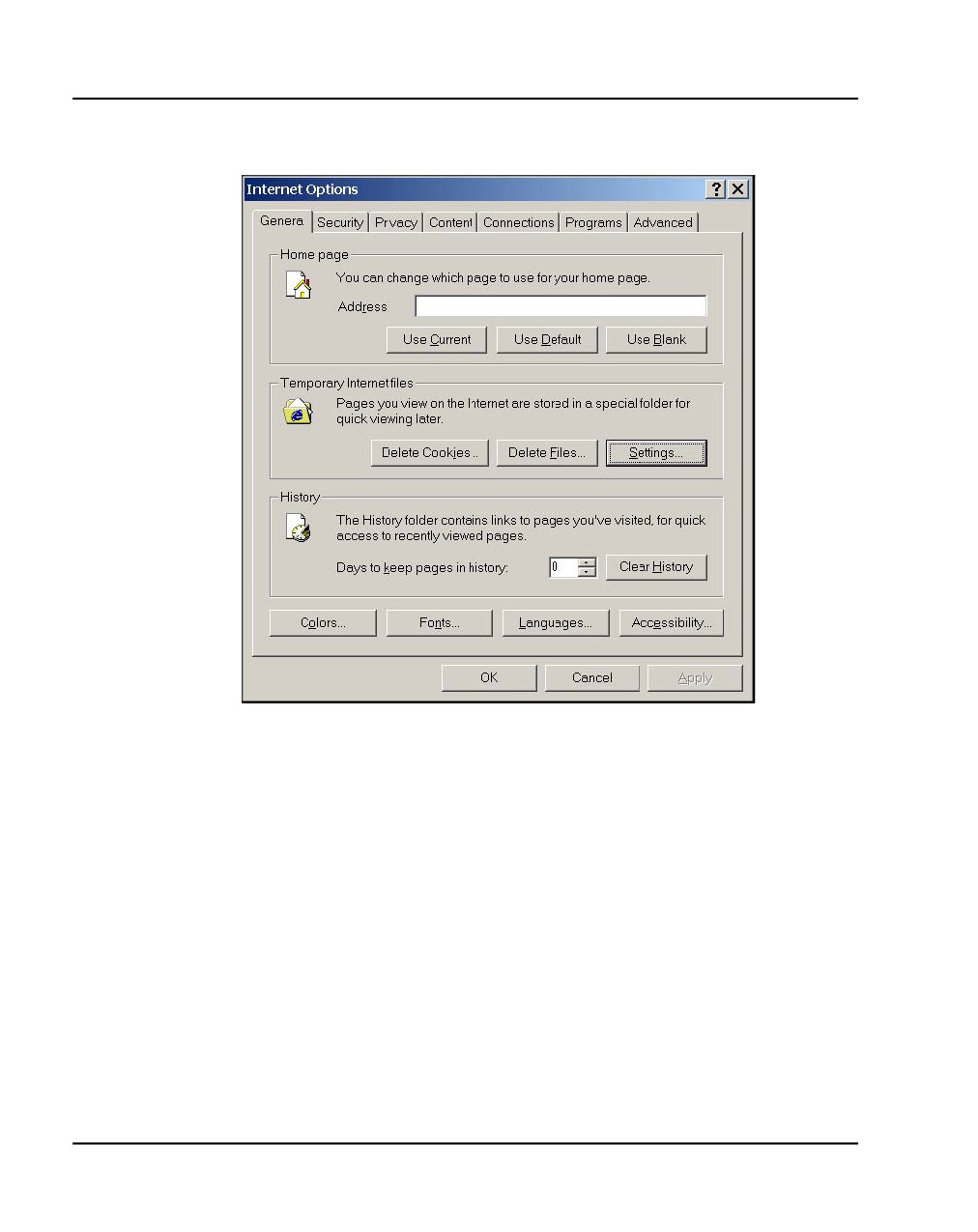
2
Click Tools > Internet Options. The Internet Options window opens
(see Figure 156 on page 364).
Communication Server 1000E Installation and Commissioning
Page 364 of 466
Configuring an IP telephony node
Figure 156
Internet Explorer - Internet Options
3
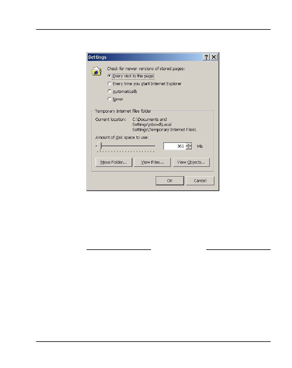
On the General tab, under the Temporary Internet files section, click
Settings. The Settings window opens (see Figure 157 on page 365).
NN43041-310
Standard 01.11
October 2008
Configuring an IP telephony node Page 365 of 466
Figure 157
Temporary Internet files - Settings window
4
Click Every visit to the page. This checks for new versions of stored
pages on every visit to the web page.
5
Click OK in the Settings window.
6
Click OK in the Internet Options window.
End of Procedure
Communication Server 1000E Installation and Commissioning
Page 366 of 466
Configuring an IP telephony node
Logging in to Element Manager
Follow Procedure 84 to log in to Element Manager.
Procedure 84
Logging in to Element Manager
1
Open the web browser.
2
Enter the Signaling Server Node IP address in the Address Bar of the
browser window, and press Enter on the keyboard.
Note: This address can be the ELAN IP, TLAN IP, or Node IP, depending
on the network in use. The ELAN IP address may be required, instead of
the Node IP address, to access to the Element Manager login web page
in secure environments.
3
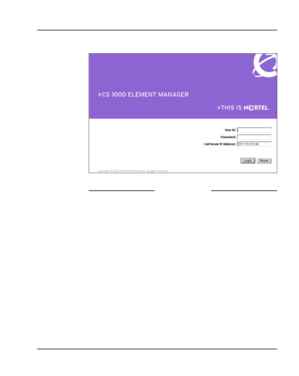
Element Manager opens and the Login web page appears (see
Figure 158 on page 367).
a. Enter the User ID and Password of the CS 1000E.
— User ID = admin1 or any LAPW
— Password = 0000
b. Enter the ELAN IP address of the CS 1000E in the CS IP Address
field.
c. Click Login.
NN43041-310
Standard 01.11
October 2008
Configuring an IP telephony node Page 367 of 466
Figure 158
Element Manager login
End of Procedure
Communication Server 1000E Installation and Commissioning
Page 368 of 466
Configuring an IP telephony node
Importing preconfigured IP telephony files
Follow Procedure 85 to import the preconfigured IP telephony files from the
Signaling Server.
Procedure 85
Importing an existing node
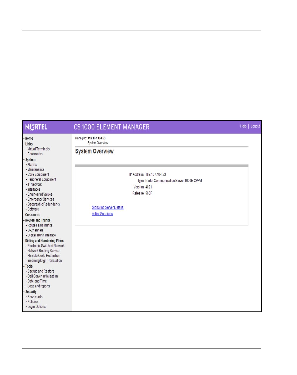
Figure 159 displays the Element Manager System Information home page.
Figure 159
Element Manager - System Overview web page
NN43041-310
Standard 01.11
October 2008
Configuring an IP telephony node Page 369 of 466
1
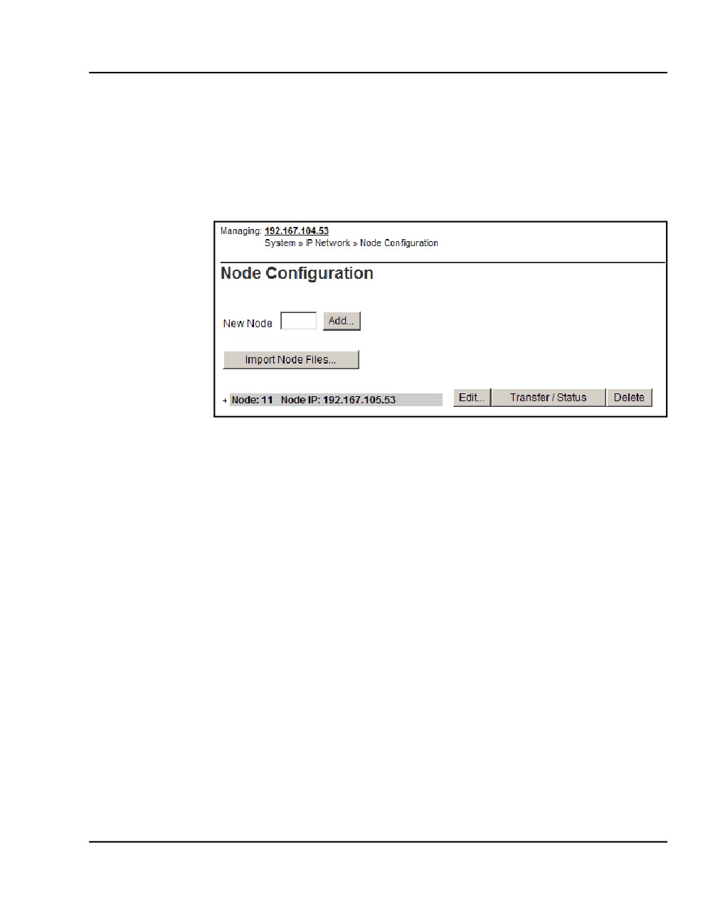
Select IP Network > Node: Servers, Media Cards from the navigator.
The Node Configuration web page opens, as shown in Figure 160. If this
is the first node to be added, the “No nodes are configured” message is
displayed.
Figure 160
Node Configuration web page
2
Import the Node files from the leader Signaling Server.
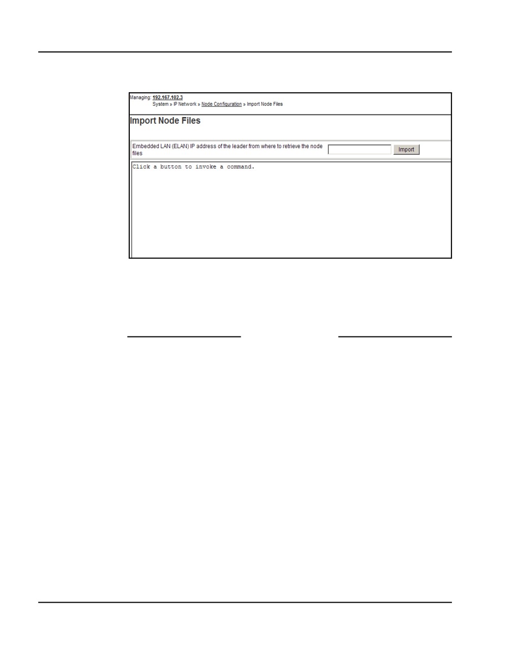
a. Click Import Node Files.
The Import Node Files screen as shown in Figure 161 on page 370
appears.
b. Enter the ELAN IP address of the leader Signaling Server in the input
box.
Communication Server 1000E Installation and Commissioning
Page 370 of 466
Configuring an IP telephony node
Figure 161
Import Node Files web page
3
Click Import.
Click OK in the dialog when the operation is complete. The Node
Summary web page is re-displayed showing the new node.
End of Procedure
Reviewing and submitting IP telephony node
configuration files
Follow Procedure 86 to review and submit IP telephony node configuration
files.
Procedure 86
Reviewing and submitting IP telephony node configuration
1
From the Node Summary web page (see Figure 127 on page 320), click
Edit to view the node parameters.
The Edit web page appears as shown in Figure 128 on page 321.
NN43041-310
Standard 01.11
October 2008
Configuring an IP telephony node Page 371 of 466
Note 1: Clicking Transfer / Status displays the Transfer / Status web
page (see Figure 165 on page 373). This sends the node configuration
files to all IP Telephony components in the node.
•
If any element within the node fails to transfer either BOOTP or
CONFIG files, Transfer / Status is highlighted in red.
•
Transfer / Status is highlighted in yellow if the transfer status of the
node elements is unavailable.
Note 2: Delete is used to delete the corresponding node. The node is not
automatically deleted. A message displays and asks if you are sure you
want to delete the node.
2
Review the node parameters by opening each tab.
Note: For detailed information on each of the node parameters, refer to
IP Line: Description, Installation, and Operation
(NN43100-500).
3
Click Save and Transfer.
4
Click OK to save the node configuration to the CS 1000E and transfer the
configuration to all elements.
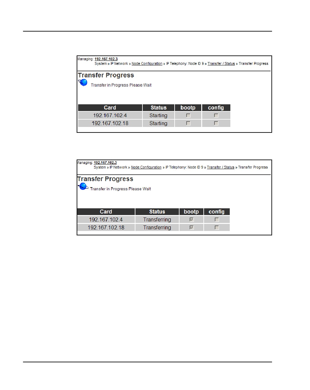
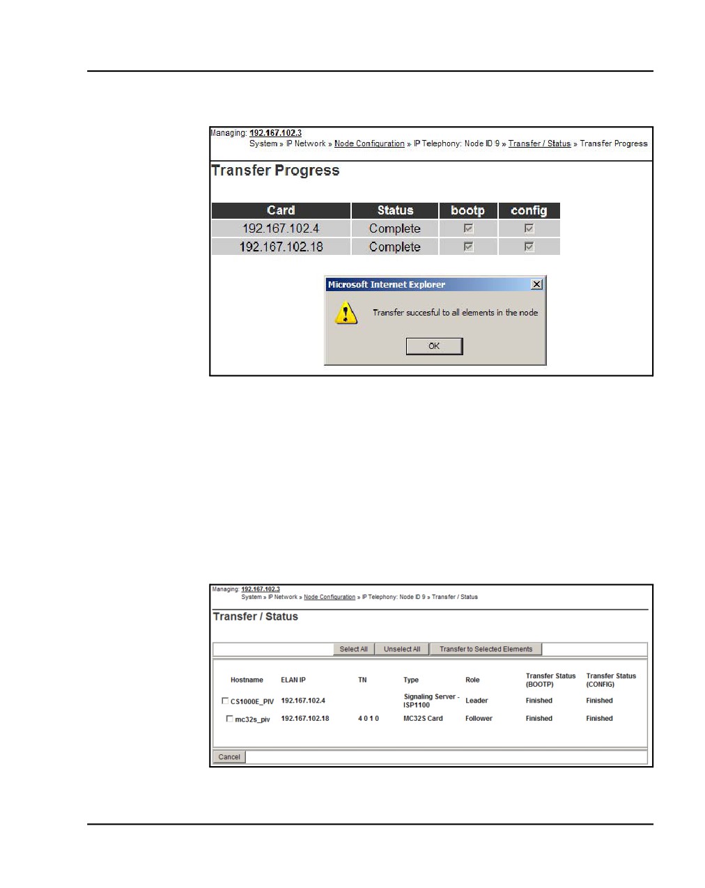
After a few seconds, the Transfer Progress web page opens and
displays each of the elements in the node (see Figure 162 on page 372).
The Voice Gateway Media Cards retrieve the CONFIG.INI and
BOOTP.TAB files from the CS 1000E. A check mark is added to each
field as the card receives its CONFIG.INI and BOOTP.TAB files.
The status column provides the progress of the transfer:
•
The Status column displays “Starting” as the transfer begins (see
Figure 162 on page 372).
•
The Status column displays “Transfer” as the node configuration is
transferred to the elements (see Figure 163 on page 372).
•
The Status column displays “Complete” if the transfer is successful
for an element (see Figure 164 on page 373).
•
The Status column displays “Fail” if the transfer is unsuccessful.
Communication Server 1000E Installation and Commissioning
Page 372 of 466
Configuring an IP telephony node
Figure 162
Transfer Progress - Starting
Figure 163
Transfer Progress - Transferring
When the file transfer is complete, the Transfer Progress web page
displays a status of complete (see Figure 164 on page 373).
NN43041-310
Standard 01.11
October 2008
Configuring an IP telephony node Page 373 of 466
Figure 164
Transfer Progress - Complete
5
Click OK in the dialog box.
The Transfer / Status web page displays.
Note: The Transfer / Status web page (see Figure 165) can also be
displayed from the Node Summary web page by clicking Transfer /
Status. This web page indicates if the transfer was successful or not. For
example, Figure 165 shows some elements as unreachable; you can
transfer to these elements again.
Figure 165
Transfer / Status web page
Communication Server 1000E Installation and Commissioning
Page 374 of 466
Configuring an IP telephony node
The previous status of the node displays, and the failure reason is
displayed for elements in nodes that failed to get configuration files
(BOOTP.TAB and CONFIG.INI) from the CS 1000E.
The Transfer / Status web page has five buttons:
•
Selected All. Selects all the elements in the node (that is, it adds a
check mark in each element’s check box).
•
Unselect All. Unselects all the elements in the node (that is, it
removes the check marks for all the selected elements).
•
Transfer to Selected Elements. Re-transfers node configuration
files only to selected elements, regardless of a “Transfer Failed”
state.
•
Transfer to Failed Elements. Transfers only node configuration files
to elements in a “Transfer Failed” state. The Transfer to Failed
Elements button is displayed only when at least one element on the
Node failed to transfer either a BOOTP.TAB or CONFIG.INI in the
previous operation.
•
Cancel. Closes the Transfer / Status pages without performing any
action, and displays the Node Summary web page.
6
If the Signaling Server configuration was changed on the Edit web page,
reboot the Signaling Server.
End of Procedure
Adding a Follower Signaling Server to an
IP telephony node
Follow Procedure 87 to add a Follower Signaling Server to the IP telephony
node in Element Manager.
Procedure 87
Adding a Follower Signaling Server to the IP telephony node in
Element Manager
Note: After software installation and reboot, the Follower Signaling
Server sends out BootP requests and waits for a response. Because the
Follower Signaling Server has not booted successfully before, it waits for
a non-existing BootP response. Do not wait for this response; proceed to
the next steps.
NN43041-310
Standard 01.11
October 2008
Configuring an IP telephony node Page 375 of 466
In Element Manager:
1
Click Edit on the Node Configuration web page (see Figure 160 on
page 369).
2
Click Add beside the Signaling Server row.
3
Enter the Follower Signaling Server data to an IP telephony node. Include
the ELAN MAC address (used to answer BootP requests).
4
Click Save and Transfer to save the changes and the Leader Signaling
Server then obtains a copy of the node files.
5
Click OK to save the node configuration to the CS 1000E and transfer the
configuration to all elements.
When the file transfer is complete, the Transfer/ Status web page
appears.
The Leader Signaling Server responds to the Follower Signaling Server's
BootP request.
The Follower Signaling Server initializes its network interfaces.
The Follower Signaling Server attempts to FTP the BOOTP.TAB file from
the node master (Leader Signaling Server).
Note: Since the Follower cannot obtain the system login and password,
the FTP fails (for first-time Follower Signaling Server installation only). It
does not have the current CONFIG.INI file that contains the CS 1000E IP
address. Subsequent FTPs succeed.
6
Transfer the node files again, so that the Follower Signaling Server
obtains a copy of CONFIG.INI.
7
Reboot the Follower Signaling Server so that all its applications can start
based on the new CONFIG.INI file.
The Signaling Server uses BootP to obtain its network data, and it then
FTPs the BOOTP.TAB file from the node master (Leader Signaling
Server).
End of Procedure
Performing a datadump
Follow Procedure 88 to perform a datadump using Element Manager. This
procedure is an alternative to using CLI to perform a datadump. The
Communication Server 1000E Installation and Commissioning
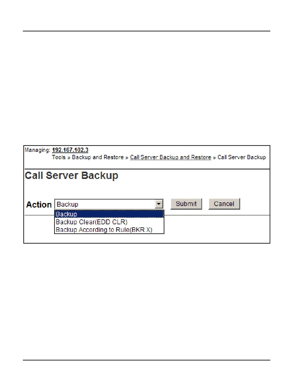
Page 376 of 466
Configuring an IP telephony node
datadump backs up new IP Telephony node files on the CS 1000E at the same
time that it backs up the customer database.
Procedure 88
Performing a datadump using Element Manager
From within Element Manager (see Figure 84 on page 366 for details on
logging in), do the following:
1
Choose Tools > Backup and Restore > Call Server from the navigator.
2
The Call Server Backup and Restore web page opens, as shown in
Figure 57 on page 172.
Figure 166
CS 1000E Backup
3
Select Backup.
The Call Server Backup web page appears (see Figure 166 on
page 376).
4
Select Backup from the Action drop-down list box.
5
Click Submit.
The message displays indicating “Backup in progress. Please wait...”
6
Click OK in the EDD complete dialog box.
The Backup function displays information in a tabular form indicating the
actions that were performed.
NN43041-310
Standard 01.11
October 2008
Configuring an IP telephony node Page 377 of 466
End of Procedure
Communication Server 1000E Installation and Commissioning
Page 378 of 466
Configuring an IP telephony node
NN43041-310
Standard 01.11
October 2008
390
Page 379 of 466
Installing Line cards and
cross-connecting telephones
Contents
This section contains information on the following topics:
Introduction
379
Card placement in a Media Gateway or a Media Gateway Expansion.
382
Cross-connecting telephones
382
Connecting a telephone without a PFTU
384
Connecting an off-premise telephone
385
Connecting an attendant console
387
Introduction
This chapter contains instructions for connecting telephone Line cards
located in the Media Gateway and Media Gateway Expander to the MDF
cross-connect terminal.
This chapter contains the following procedures:
•
Procedure 89: "Cross-connecting telephones" on page 382
•
Procedure 90: "Connecting a telephone without a PFTU" on page 385
•
Procedure 91: "Connecting an off-premise telephone" on page 386
•
Procedure 92: "Connecting an attendant console" on page 387
Communication Server 1000E Installation and Commissioning
Page 380 of 466
Installing Line cards and cross-connecting telephones
Before you proceed, install the cable from the slot that contains the Line card
associated with the telephone being connected. Refer to “Installing the Main
Distribution Frame” on page 349, if you require additional cable installation.
DANGER OF ELECTRIC SHOCK
Always use caution when installing or modifying
telephone lines. Do not install telephone wiring during a
lightning storm. Do not install telephone jacks in wet
locations unless the jacks are designed for wet locations.
Never touch uninsulated telephone wiring unless the line
is disconnected at the network interface.
Refer to the Circuit Card: Description and Installation (NN43001-311) for
full descriptions of country-specific IPE cards and their installation
procedures
Figure 167 and Figure 168 on page 381 show the circuit card assignments for
the Media Gateway and Media Gateway Expander. Refer to these figures to
make sure that you have all circuit cards inserted in the correct slots.
NN43041-310
Standard 01.11
October 2008
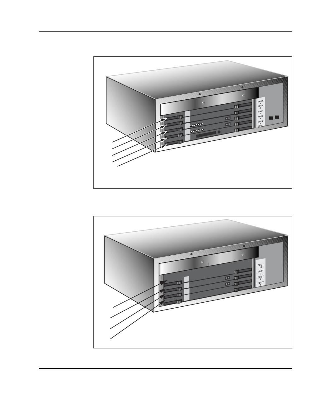
Installing Line cards and cross-connecting telephones
Page 381 of 466
Figure 167
Circuit card assignments in a Media Gateway
Slot 4
Slot 3
Slot 2
Slot 1
Slot 0 - SSC
553-CSE9025
Figure 168
Circuit card assignments in a Media Gateway Expander
Slot 10
Slot 9
Slot 8
Slot 7
553-CSE9032
Communication Server 1000E Installation and Commissioning
Page 382 of 466
Installing Line cards and cross-connecting telephones
Circuit cards features
If a circuit card has a switch symbol on its faceplate, it is equipped with option
switches, strapping plugs, or both. Make sure that the circuit cards with option
switches or strapping plugs are set correctly. Some circuit cards can have
daughterboards and other add-on devices installed on them.
Card placement in a Media Gateway or a Media Gateway
Expansion
The work order developed by the planning and engineering department
outlines the placement of peripheral cards in the Media Gateway and Media
Gateway Expander slots. See Circuit Card: Description and Installation
(NN43001-311) for card placement into card slots. The 48-port Digital Line
Card is not supported.
Cross-connecting telephones
Connect the telephones according to Figure 169 on page 383 and Figure 170
on page 384.
Procedure 89
Cross-connecting telephones
1
Locate the telephone terminations at the cross-connect terminal.
2
Connect the Z-type cross-connect wire to the leads of the telephone.
3
Locate line circuit card (TN) terminations at the cross-connect terminal.
4
Connect the other end of the cross-connect wire to the assigned TN
terminal block.
NN43041-310
Standard 01.11
October 2008
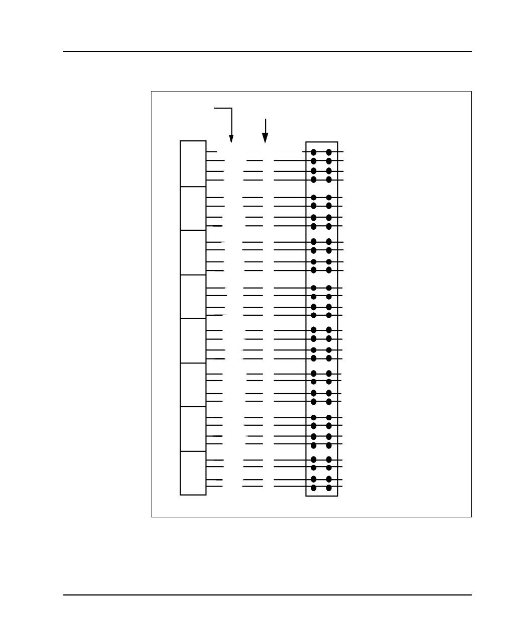
Installing Line cards and cross-connecting telephones
Page 383 of 466
Figure 169
NE-500/2500-type telephone cross connections
Lead
Cable pairs
designation
Line
Cross connect
Pack
terminal
Unit
W-BL
T
To 500/2500-type
0
BL-W
R
telephone
Unit
W-O
T
To 500/2500-type
1
O-W
R
telephone
Unit
W-G
T
To 500/2500-type
2
G-W
R
telephone
Unit
W-BR
T
To 500/2500-type
3
BR-W
R
telephone
Unit
W-S
T
To 500/2500-type
4
S-W
R
telephone
Unit
R-BL
T
To 500/2500-type
5
BL-R
R
telephone
Unit
6
R-O
T
To 500/2500-type
O-R
R
telephone
Unit
R-G
T
To 500/2500-type
7
telephone
G-R
R
Unit
R-BR
T
To 500/2500-type
8
BR-R
R
telephone
Unit
R-S
T
To 500/2500-type
9
S-R
R
telephone
Unit
BK-BL
T
To 500/2500-type
10
BL-BK
R
telephone
Unit
BK-O
T
To 500/2500-type
11
O-BK
R
telephone
Unit
BK-G
T
To 500/2500-type
12
G-BK
R
telephone
Unit
BK-BR
T
To 500/2500-type
13
BR-BK
R
telephone
Unit
BK-S
T
To 500/2500-type
14
S-BK
R
telephone
Unit
Y-BL
T
To 500/2500-type
15
BL-Y
R
telephone
553-8349.EPS
Communication Server 1000E Installation and Commissioning
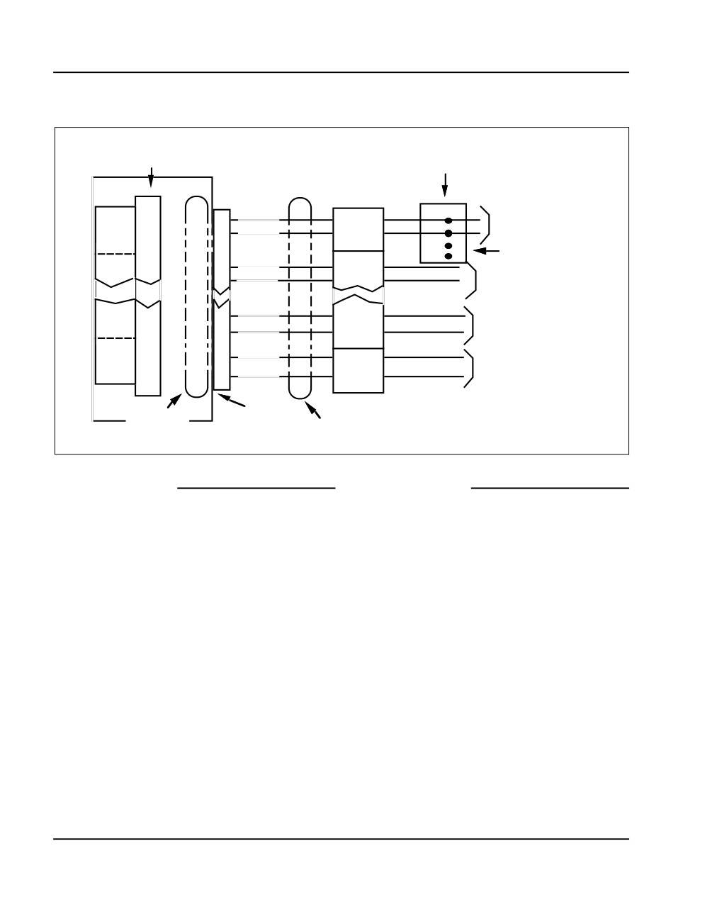
Page 384 of 466
Installing Line cards and cross-connecting telephones
Figure 170
Digital telephone cross connections
Pack
Telephone connecting
connector
block, or connector
PE shelf
Line
Cross connect
pack
block
T0
G
Line cord
26
W-BL
T0
Unit 0
R0
R
to telephone
1
BL-W
R0
W
For Power
T1
B
Supply leads
27
T1
Unit
1
R1
W-O
2
R1
O-W
to telephone
T14
Unit 14
40
BK-S
T14
R14
15
R14
to telephone
S-BK
Unit 15
T15
40
T15
Y-BL
R15
to telephone
16
BL-Y
R15
Part of
Shelf
Part of 25
25 pair cable
connector
pair cable
553-8350.EPS
End of Procedure
Connecting a telephone without a PFTU
See “Installing and cross-connecting a Power Fail Transfer Unit” on
page 437 for connecting telephones with the PFTU.
NN43041-310
Standard 01.11
October 2008
Installing Line cards and cross-connecting telephones
Page 385 of 466
Procedure 90
Connecting a telephone without a PFTU
1
Locate the telephone terminations on the cross-connect terminal.
2
Connect one end of the cross-connect wire to the leads of the telephone.
3
Locate the Line card terminations on the cross-connect terminal.
4
Connect the other end of the cross-connect wire to the assigned TN
terminal block.
5
Activate the telephone.
End of Procedure
Connecting an off-premise telephone
Connect off-premise analog (500/2500-type) telephones through an NT1R20
Off-premise Line card or NTAK92AA Off-Premise Protection Module. Each
NTAK92AA module can connect up to four analog (500/2500-type)
telephones and can interface with the NT8D09 Message Waiting Line card.
DANGER OF ELECTRIC SHOCK
The message-waiting Line card produces -150 volts,
which is considered hazardous on off-premise
telephones. Make sure that the -150 volts are disabled
on off-premise telephones.
The voltage is disabled when the telephone’s Class of
Service (CLS) is Message Waiting Lamp Denied (LPD)
and Message Waiting Denied (MWD) in LD 10.
Refer to the Software Input/Output: Administration
(NN43001-611) for information about LD 10.
Do not assign a Class of Service of LPA or MWA to an
off-premise telephone.
Communication Server 1000E Installation and Commissioning
Page 386 of 466
Installing Line cards and cross-connecting telephones
Procedure 91
Connecting an off-premise telephone
1
Install the NTAK92BA Off-Premise Protection Module on the wall using
four #10 1/2-in (minimum) screws.
2
Connect a #6 AWG from the grounding lug at the bottom of the
NTAK92AA Off-Premise Protection Module to the system ground. Refer
to Figure 171 on page 387.
DANGER OF ELECTRIC SHOCK
If connecting to a message-waiting Line card, unseat the
card from its assigned slot before continuing with the
next step.
3
Connect two NTAK9204 cables (one from connector J1 and one from
connector J2) from the protection module to the cross-connect terminal.
4
Terminate the cables as shown in Figure 169 on page 383.
5
Cross-connect the J1 cable to the Tip and Ring connections coming from
the Line card.
6
Cross-connect the J2 cable to the off-premise telephone.
7
Install the regulatory label provided with the Off-Premise Protection
Module on the inside right-hand wall of the Media Gateway.
8
Install the Line card in its assigned position.
9
Activate the telephone.
NN43041-310
Standard 01.11
October 2008
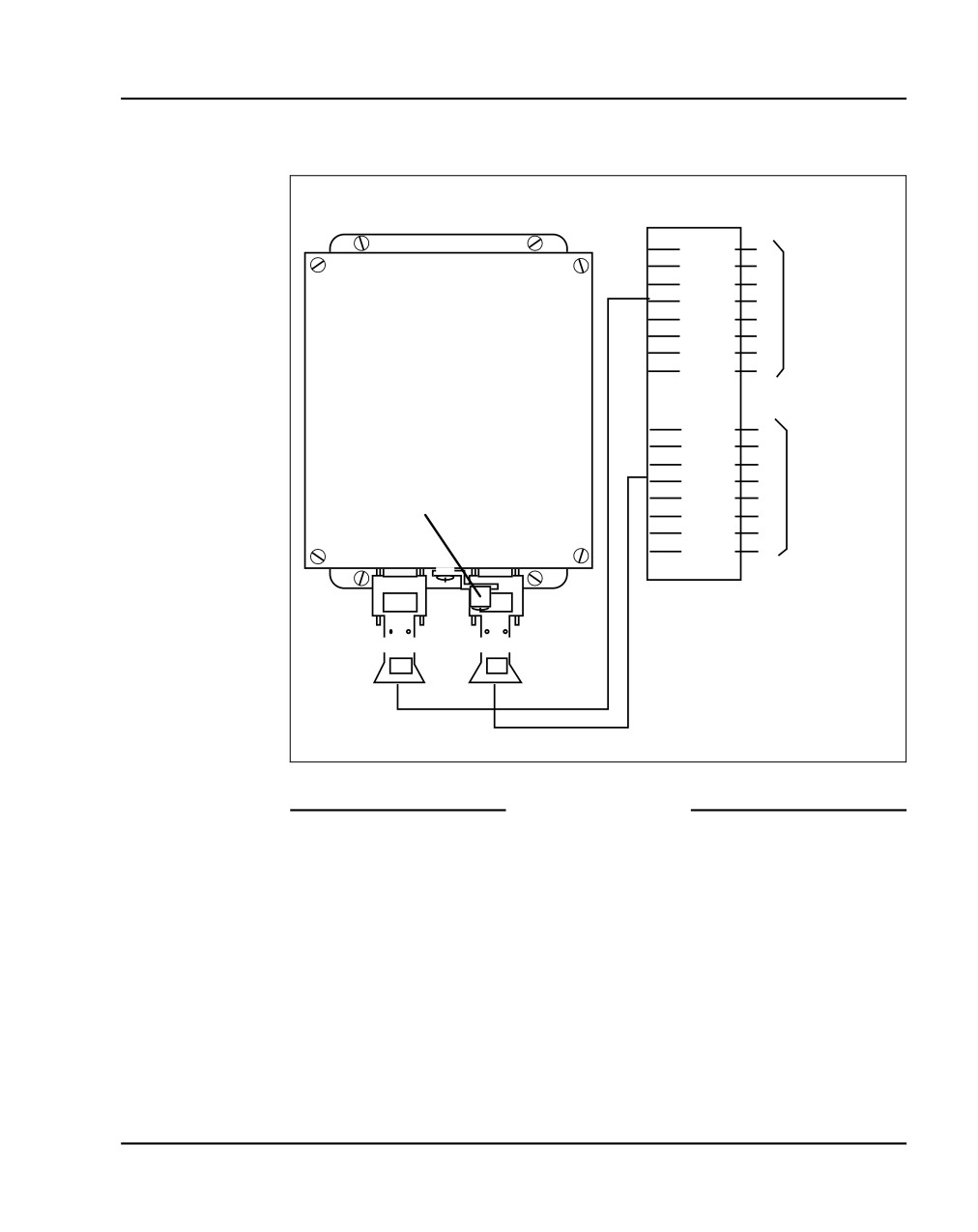
Installing Line cards and cross-connecting telephones
Page 387 of 466
Figure 171
NTAK92BA Off-Premise Protection Module connections
Cross-connect
terminal block
BL - 1W
T1
BL - 2W
R1
O - 1W
T2
J2
O - 2W
R2
To off-premise
G - 1W
T3
telephones
G - 2W
R3
BR - 1W
T4
BR - 2W
R4
NTAK92AA
Off-Premise
Protection
Module
BL - 1W
T1
BL - 2W
R1
O - 1W
T2
To analogue
J1
O - 2W
R2
line card in
G - 1W
T3
Option 11
Ground lug
G - 2W
R3
cabinet
BR - 1W
T4
BR - 2W
R4
Connector J2
Connector J1
NTAK9204
Cable
NTAK9204
Cable
553-8351.EPS
End of Procedure
Connecting an attendant console
Procedure 92
Connecting an attendant console
1
Locate the attendant console terminations at the cross-connect terminal.
2
Locate the Line card terminations at the cross-connect terminal.
3
With cross-connect wire, connect the Line card and other connections to
the console, as shown in Figure 172 on page 388.
Communication Server 1000E Installation and Commissioning
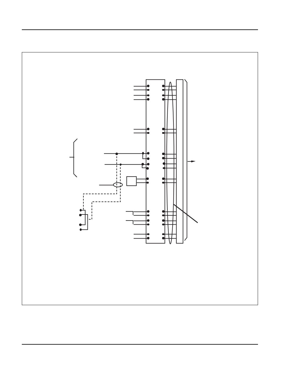
Page 388 of 466
Installing Line cards and cross-connecting telephones
Figure 172
Attendant console connections
Cross-connect
Console
block
connector
W-BL
26
To 1st TN
BL-W
1
W-O
27
To 2nd TN
O-W
2
ASM/
W-S
30
To 3rd TN
ADN
S-W
5
To +15 AUX
Console power
(W-G 1 dot wire)
+ AUX
R-O
32
from AUX
on AUX cable
Cable to
O-R
7
cable
To -15 AUX
- AUX
M2250
33
(one console
(G-W 1 dot wire)
R-G
Console
8
only)
on AUX cable
G-R
GND
BK-BL
36
Note: As an alternative, console
TC
BL-BK
11
power can be obtained from the
4 th and 5 th TNs on the circuit
card.
To 4th TN Tip
+VPS
Y-BL
41
To 4th TN Ring
(Note 2)
BL-Y
16
+VPS RTN
Y-O
42
To 5 th TN Tip
O-Y
17
Cable from
To 5 th TN Ring
console to
(Note 1)
Relay 2
V-S
50
cross-connect
Relay 1
S-V
25
terminal
Note 1: The M2250 is powered using the line circuits and if required from the AUX cable. In addition to
the primary TN, secondary TN and ASMTN, two TNs are for power from the AUX cable are cabled to
the M2250 through the + AUX and - AUX leads. Maximum loop length is 3000 ft (915 m) of 24 AWG
(5.0 Metric Wire Gauge).
Note 2: When additional options are used (BLF), an additional 16V DC power supply is
required. The 16V DC source is cabled through +VPS and +VPS RTN leads. The maximum
distance from the console to the power source is 120 ft (36 m) of 24 AWG (5.0 Metric Wire Gauge) wire.
553-8352.EPS
NN43041-310
Standard 01.11
October 2008

Installing Line cards and cross-connecting telephones
Page 389 of 466
Table 46
Color combinations of cable pairs
W-Bl
W-O
W-G
W-BR
W-S
R-BL
R-O
R-G
Color
Bl-W
O-W
G-W
BR-W
S-W
BL-R
O-R
G-R
Unit
0
1
2
3
4
5
6
7
R-BR
R-S
BK-BL
BK-O
BK-G
BK-BR
BK-S
Y-B
Color
BR-R
S-R
BL-BK
O-BK
G-BK
BR-BK
S-BK
B-Y
Unit
8
9
10
11
12
12
14
15
End of Procedure
Communication Server 1000E Installation and Commissioning
Page 390 of 466
Installing Line cards and cross-connecting telephones
NN43041-310
Standard 01.11
October 2008
436
Page 391 of 466
Installing and configuring
Nortel IP Phones
Contents
This section contains information on the following topics:
Introduction
392
Configuring VoIP bandwidth management zones
406
Configuring virtual superloops
408
Configuring a Nortel IP Phone using LD 11
408
Setting administrator and temporary IP Telephone Installer passwords
414
Installing Nortel IP Phone hardware components
417
Configuring the Nortel IP Phone boot parameters
421
Entering Nortel IP Phone boot parameters using manual configuration
422
Entering Nortel IP Phone boot parameters using full DHCP parameters
425
Entering boot parameters using partial DHCP parameters
427
Using Set-Based Installation
430
Installing the IP Softphone 2050
432
Verifying Nortel IP Phone functionality
436
Displaying registered IP Phones
436
Upgrading firmware
436
Communication Server 1000E Installation and Commissioning
Page 392 of 466
Installing and configuring Nortel IP Phones
Introduction
For detailed information on the various telephones supported on the
CS 1000E system, refer to Telephones and Consoles: Description,
Installation, and Operation (NN43001-567) and IP Phones: Description,
Installation, and Operation (NN43001-368).
The following Nortel IP Phones can be installed on a CS 1000E system:
•
Nortel IP Phone 2001, Nortel IP Phone 2002, Nortel IP Phone 2004 and
Nortel IP Phone 2007
•
Nortel IP Softphone 2050
•
Nortel IP Audio Conference Phone 2033
•
Nortel IP Phone 1120E, Nortel IP Phone 1140E and Nortel IP Phone
1150E
•
Nortel IP Phone 1110
•
Expansion Module for IP Phone 1100 Series
•
WLAN Handsets 2210/2211/2212
•
MVC 2050
The system must be configured before the Nortel IP Phones can be installed.
The configuration includes:
•
The Nortel IP Phone TN blocks must be defined on the Call Server (See
“Configuring VoIP bandwidth management zones” on page 406 or
“Using Set-Based Installation” on page 430).
•
The IP Phones are assigned to an IP telephony node, and use the IP
telephony node properties defined using Element Manager (see
“Configuring an IP telephony node” on page 361).
•
The IP Phones require local boot parameter configuration (see
“Configuring the Nortel IP Phone boot parameters” on page 421).
NN43041-310
Standard 01.11
October 2008
Installing and configuring Nortel IP Phones
Page 393 of 466
Package components for the Nortel IP Phones
Table 47 lists the Nortel IP Phone 2001 package components and product
codes.
Table 47
Nortel IP Phone 2001 components list (Part 1 of 2)
Nortel IP Phone 2001 package contents include:
• Nortel IP Phone 2001
• Handset
• Handset cord
• Footstand
•
7 ft. Cat5 Ethernet cable
• Getting Started card
Nortel IP Phone 2001(Ethergray) with Icon keycaps
NTDU90AA16/A0533387
Nortel IP Phone 2001 (Ethergray) with English text label
NTDU90BA16/A0533388
keycaps
Nortel IP Phone 2001 (Charcoal) with Icon keycaps
NTDU90AA70/A0053389
Nortel IP Phone 2001 (Charcoal) with English text label keycaps
NTDU90BA70/A0533390
Nortel IP Phone 2001 (Charcoal with Bezel) with Icon keycaps
NTDU90AB70
Nortel IP Phone 2001 (Charcoal with Bezel) with Icon keycaps
NTDU90AC70E6
(RoHS)
Nortel IP Phone 2001 (Charcoal with Bezel) with English text
NTDU90BB70
label keycaps
Nortel IP Phone 2001 (Charcoal with Bezel) with English text
NTDU90BC70E6
label keycaps (RoHS)
Replacement parts
7 ft. Cat5 Ethernet Cable
A0648375
Handset, Ethergray
A0788874
Communication Server 1000E Installation and Commissioning
Page 394 of 466
Installing and configuring Nortel IP Phones
Table 47
Nortel IP Phone 2001 components list (Part 2 of 2)
Handset, Charcoal
A0758634
Handset cord, Ethergray; for Nortel IP Phone 2004 and Nortel IP
A088682
Phone 2001
Handset cord, Charcoal; for Nortel IP Phone 2004 and Nortel IP
N0000764
Phone 2001
Nortel IP Phone 2001/2002/2004 Power Adapters
Power transformer (117/120 VAC 50/60 Hz) (North America)
A0619627
Power transformer 3 prong AC to AC, direct plug-in, 8W, 240
A0656598
VAC, 50Hz to 16 VAC at 500 mA (Ireland and UK)
Power transformer AC to AC, direct plug-in, 8W, 230 VAC, 50/
A0619635
60 Hz, to 16 VAC at 500 mA (Europe)
Power transformer 2 prong wall plug direct plug-in AC to AC,
A0647042
8W, 240 VAC, 50 Hz, to 16 VAC at 500 mA (Australia and New
Zealand)
Power transformer AC to AC, direct plug-in, 8W, 100 VAC, 50
A0828858
Hz, to 16 VAC at 500 mA
NN43041-310
Standard 01.11
October 2008
Installing and configuring Nortel IP Phones
Page 395 of 466
Table 48 lists the Nortel IP Phone 2002 package components and product
codes.
Table 48
Nortel IP Phone 2002 components list (Part 1 of 2)
Nortel IP Phone 2002 package contents include:
• Nortel IP Phone 2002
• Handset
• Handset cord
• Footstand
•
7ft Cat5 Ethernet cable
• Getting Started card
Nortel IP Phone 2002 (Ethergray) with Icon keycaps
NTDU91AA16/A0533404
Nortel IP Phone 2002 (Ethergray) with English text label
NTDU91BA16/A0533405
keycaps
Nortel IP Phone 2002 (Charcoal) with Icon keycaps
NTDU91AA70/A0533406
Nortel IP Phone 2002 (Charcoal) with English text label keycaps
NTDU91BA70/A0533407
Nortel IP Phone 2002 (Charcoal with Bezel) with Icon keycaps
NTDU91AB70
Nortel IP Phone 2002 (Charcoal with Bezel) with Icon keycaps
NTDU91AC70E6
(RoHS)
Nortel IP Phone 2002 (Charcoal with Bezel) with English text
NTDU91BB70
label keycaps
Nortel IP Phone 2002 (Charcoal with Bezel) with English text
NTDU91BC70E6
label keycaps (RoHS)
Replacement parts
7 ft. Cat5 Ethernet cable
A0648375
Handset, Ethergray
A0788874
Handset, Charcoal
A0758634
Communication Server 1000E Installation and Commissioning
Page 396 of 466
Installing and configuring Nortel IP Phones
Table 48
Nortel IP Phone 2002 components list (Part 2 of 2)
Handset cord, Ethergray
A0897725
Handset cord, Charcoal
N0000763
Footstand, Charcoal (used for Ethergray and Charcoal models)
A0891619
IP Phone 2001/2002/2004 Power Adaptors
Power transformer (117/120 VAC 50/60 Hz) (North America)
A0619627
Power transformer 3 prong AC to AC, direct plug-in, 8W, 240
A0656598
VAC, 50Hz to 16 VAC at 500 mA (Ireland and UK)
Power transformer AC to AC, direct plug-in, 8W, 230 VAC, 50/
A0619635
60 Hz, to 16 VAC at 500 mA (Europe)
Power transformer 2 prong wall plug direct plug-in AC to AC,
A0647042
8W, 240 VAC, 50 Hz, to 16 VAC at 500 mA (Australia and New
Zealand)
Power transformer AC to AC, direct plug-in, 8W, 100 VAC, 50
A0828858
Hz, to 16 VAC at 500 mA
NN43041-310
Standard 01.11
October 2008
Installing and configuring Nortel IP Phones
Page 397 of 466
Table 49 lists the Nortel IP Phone 2004 package components and product
codes.
Table 49
IP Phone 2004 component list (Part 1 of 2)
IP Phone 2004package contents includes
• IP Phone 2004
• Handset
• Handset cord
• Footstand
•
7 ft. Ethernet cable
• Getting Started card
Nortel IP Phone 2004 (Ethergray) with Icon keycaps
NTDU92AA16/
A0533408
Nortel IP Phone 2004 (Ethergray) with English text label keycaps
NTDU92BA16/
A0533409
Nortel IP Phone 2004 (Charcoal) with Icon keycaps
NTDU92AA70/
A0533410
Nortel IP Phone 2004 (Charcoal) with English text label keycaps
NTDU92BA70/
A0533411
Nortel IP Phone 2004 (Charcoal with Bezel) with Icon keycaps
NTDU92AB70
Nortel IP Phone 2004 (Charcoal with Bezel) with Icon keycaps
NTDU92AC70E6
(RoHS)
Nortel IP Phone 2004 (Charcoal with Bezel) with English text label
NTDU92BB70
keycaps
Nortel IP Phone 2004 (Charcoal with Bezel) with English text label
NTDU92BC70E6
keycaps (RoHS)
Nortel IP Phone 2004 wall mount kit (Charcoal), used with
NTMN15BA70/
Ethergray and Charcoal models
A0503076
Communication Server 1000E Installation and Commissioning
Page 398 of 466
Installing and configuring Nortel IP Phones
Table 49
IP Phone 2004 component list (Part 2 of 2)
Replacement parts
7 ft. Ethernet Cat5 cable
A0648375
Handset (Ethergray)
A0788874
Handset (Charcoal)
A0758634
Handset cord (Ethergray)
A0788682
Handset cord (Charcoal)
N0000764
Footstand (Charcoal), used for Ethergray and Charcoal models
A0538587
IP Phone 2004 Power Adaptors
Power transformer (117/120 VAC 50/60 Hz) (North America)
A0619627
Power transformer 3 prong AC to AC, direct plug-in, 8W, 240 VAC,
A0656598
50Hz to 16 VAC at 500 mA (Ireland and UK)
Power transformer AC to AC, direct plug-in, 8W, 230 VAC, 50/60
A0619635
Hz, to 16 VAC at 500 mA (Europe)
Power transformer 2 prong wall plug direct plug-in AC to AC, 8W,
A0647042
240 VAC, 50 Hz, to 16 VAC at 500 mA (Australia and New Zealand)
Power transformer AC to AC, direct plug-in, 8W, 100 VAC, 50 Hz, to
A0828858
16 VAC at 500 mA
NN43041-310
Standard 01.11
October 2008
Installing and configuring Nortel IP Phones
Page 399 of 466
Table 50 lists the Nortel IP Phone 2007 package components and product
codes.
Table 50
Nortel IP Phone 2007 component list (Part 1 of 2)
Nortel IP Phone 2007 package contents includes
NTDU96AB70
• Nortel IP Phone 2007(charcoal with metallic bezel)
• Handset
• Handset cord
• Footstand
•
7 ft. (2.3 m) CAT5 Ethernet cable
• Getting Started card
Replacement parts
7 ft. CAT5 Ethernet cable
A0648375
Handset (charcoal)
A0758634
Handset cord (charcoal)
N0000764
Footstand (charcoal)
A0538587
Nortel IP Phone 2007 power adapter
Global power adapter
N0014020
Nortel IP Phone 2007 power cords
Cord 9.9 ft. NA Power, NEMA, 125Vac 13a
NTTK14AB
NA, M.East, Taiwan, Indonesia, Philippines, Korea, Thailand,
Vietnam, Japan
Cord 8 ft., ANA Power AS-3, 240Vac 10A
NTTK15AA
Australia, New Zealand, PRC
Option 11C Standard European Power Cord 250Vac
NTTK16AB
Other EMEA, Kenya
Option 11C Swiss Power Cord, 9.9 ft. 125Vac
NTTK17AB
Switzerland
Communication Server 1000E Installation and Commissioning
Page 400 of 466
Installing and configuring Nortel IP Phones
Table 50
Nortel IP Phone 2007 component list (Part 2 of 2)
Option 11C UK Power Cord 240Vac
NTTK18AB
Hong Kong, Ireland, UK, Singapore, Malaysia, India, Bangladesh,
Pakistan, Brunei, Sri Lanka
Option 11C Denmark Power Cord Kit, 9.9 ft. 125Vac
NTTK22AB
Denmark
Table 51 lists the Nortel IP Phone ACP 2033 package components and
product codes.
Table 51
Nortel IP Audio Conference Phone 2033 components list
IP Audio Conference Phone 2033 package contents include:
• IP Audio Conference Phone 2033 (charcoal)
NTEX11AA70
•
7 ft. CAT5 Ethernet cable
• Power Interface Module (PIM) with 25 ft. console cable
• IP Audio Conference Phone 2033 Quick Reference Card
• Universal power supply
IP Audio Conference Phone 2033 package contents include:
NTEX11BA70
• IP Audio Conference Phone 2033 (charcoal)
•
7 ft. CAT5 Ethernet cable
• Power Interface Module (PIM) with 25 ft. console cable
• IP Audio Conference Phone 2033 Quick Reference Card
•
2 Extension microphones (charcoal)
• Universal power supply
Additional Extension microphones with 7 ft. cable
NTEX11DA70
Power accessory kit (PIM, Universal power supply, cabling)
NTEX11CA
Nortel IP Phone IP Audio Conference Phone 2033 Power cords
NN43041-310
Standard 01.11
October 2008