Nortel Communication Server 1000. Installation And Commissioning Manual (2008) - page 1
Title page
Nortel Communication Server 1000
Nortel Communication Server 1000 Release 5.0
Communication Server 1000E
Installation and Commissioning
Document Number: NN43041-310
Document Release: Standard 01.11
Date: October 2008
Year Publish FCC TM
12
Page 3 of 466
Contents
List of Procedures
13
Revision history
21
How to get help
23
Getting help from the Nortel Web site
23
Getting help over the telephone from a Nortel Solutions Center
23
Getting help from a specialist by using an Express Routing Code
24
Getting help through a Nortel distributor or reseller
24
Finding the latest updates
on the Nortel web site
25
System information
27
Subject
27
Applicable systems
28
Conventions
28
Related information
28
Safety instructions
31
Contents
31
Introduction
31
Lifting system equipment
32
Handling circuit cards
32
Installing telephones
33
Communication Server 1000E Installation and Commissioning
Page 4 of 466
Contents
Using telephones
33
Installation summary
35
Contents
35
Introduction
35
Installation tasks
36
System components
39
Contents
39
Introduction
40
CS 1000E Common Processor Pentium Mobile Call Server
43
Signaling Server
52
Media Gateway Controller
58
MC32S Media Card
59
Media Card
59
Media Gateway
61
Media Gateway Expander
67
19-inch Rack Mount Kit
70
BayStack 470 Switch
71
BayStack 460 Layer 2 switch
73
MRV Terminal Server
73
19-inch rack
75
System cables
75
Miscellaneous system components
78
Uninterruptible Power Supply
78
Rack-mounting the components
81
Contents
81
Introduction
81
Lifting system components
82
Guidelines for component placement in a rack
83
NN43041-310
Standard 01.11
October 2008
Contents
Page 5 of 466
Rack-mounting a Media Gateway or Media Gateway Expander
84
Rack-mounting a Terminal Server
90
Rack-mounting a BayStack 470 Switch
90
Rack-mounting a BayStack 460 Power over Ethernet unit
90
Installing system grounds
91
Contents
91
Introduction
91
Installing a ground bar
92
Grounding an ISP1100 Signaling Server
95
Grounding a Media Gateway powered by the same electrical panel . .
95
Grounding a Media Gateway powered by multiple electrical panels . .
97
Grounding a Media Gateway Expander
97
Grounding other rack-mounted components
98
Grounding equipment in the UK
100
Installing and connecting CS 1000E hardware . . .
101
Contents
101
Introduction
101
Connecting CP PM Call Server 0 to CP PM Call Server 1
102
Installing the cards
104
Cabling the cards
107
Inserting a Shielded 50-pin to Serial/ELAN/TLAN
adapter onto a Media Card
112
Connecting a Media Card to the ELAN subnet
114
Connecting a Media Card to the TLAN subnet
115
Connecting a Media Gateway to a Media Gateway Expansion
115
Installing software on the CS 1000E
117
Contents
117
Introduction
117
Installing the software
118
Communication Server 1000E Installation and Commissioning
Page 6 of 466
Contents
Configuring initial IP configuration data on MGC
143
Configuring the CS 1000E CP PM
Call Server
151
Contents
151
Introduction
152
Configuring login IDs and passwords
153
Enabling the multi-user option
156
Configuring pseudo-terminals (PTYs)
157
Checking PTY status
159
Configuring Virtual Tone and Conference Circuits
160
Configuring the MG 1000E Bandwidth Management Zones
161
Configuring the MG 1000E ports
163
Configuring Digitone Receivers
164
Configuring Tone Detectors
165
Logging in to Element Manager
165
Importing preconfigured IP telephony files
168
Reviewing and submitting IP telephony node configuration files
170
Adding a Follower Signaling Server to an IP telephony node
170
Performing a datadump
170
Installing a Signaling Server
173
Contents
173
Introduction
174
Readiness checklist
175
Installing the CP PM Signaling Server hardware
177
Connections
179
Installing the Signaling Server software
189
First boot of a new Nortel CP PM Signaling Server
216
Unpacking Help files for Virtual Terminal Emulator
235
Logging in to the Signaling Server
235
NN43041-310
Standard 01.11
October 2008
Contents
Page 7 of 466
Verifying a successful configuration
237
Testing the Leader Signaling Server
237
Configuring the IPMG
239
Contents
239
Configuring the IPMG in Element Manager
239
Configuring conference TDS
243
Configuring DSP Daughterboard Voice gateway channels
248
Connecting an IR-8020M-101
Terminal Server
251
Contents
251
Introduction
251
Configuring a Terminal Server
253
Telnet Terminal Server virtual management port
256
Telnet CS 1000E COM port from a PC
257
Configuring a transparent rlogin port
258
Accessing an MRV Console Port through the on-board modem
262
CS 1000E COM port types
263
Connecting an MRV LX8020S-102AC-R Terminal
Server
265
Contents
265
Introduction
265
Configuring a Terminal Server
268
Telnet Terminal Server virtual management port
271
Telnet to CS 1000E COM port from a PC
271
Configuring an rlogin port for various applications
273
Accessing an MRV Console Port through the on-board modem
276
CS 1000E COM port types
277
Communication Server 1000E Installation and Commissioning
Page 8 of 466
Contents
Configuring a terminal and SDI ports
279
Contents
279
Introduction
279
Setting the TTY terminal port
280
Traditional terminal SDI connection
280
CS 1000E CP PM Call Server COM Port connections
281
MG 1000E SDI connection
282
BayStack 470 SDI connection
285
Media Card SDI connection
285
Installing and cross-connecting a trunk card . . .
287
Contents
287
Introduction
287
Circuit card options
291
Digital trunk cards
291
Connecting a trunk
292
Universal Trunk card connections
293
E&M Trunk card connections
296
Trunk connections (Europe)
298
Trunk connections (UK)
308
Verifying trunk functionality
316
Installing and configuring a
Voice Gateway Media Card
317
Contents
317
Introduction
318
Configuring a card
319
Adding a card to an IP telephony node
319
Configuring a card as a node Leader
322
Configuring voice gateway channels using Element Manager
323
Configuring voice gateway channels using LD 14
325
NN43041-310
Standard 01.11
October 2008
Contents
Page 9 of 466
Saving configuration changes
327
Installing a CompactFlash
328
Installing a card in a Media Gateway
333
Verifying a card
336
Disabling a card
344
Disabling a card unit
345
Enabling a card
346
Enabling a card unit
347
Verifying functionality
348
Upgrading loadware
348
Installing the Main Distribution Frame
349
Contents
349
Introduction
349
Terminal block requirements
350
Installing a BIX cross-connect terminal
350
Installing a Krone Test Jack Frame for the UK
352
Connecting the cables to the Media Gateways
356
Configuring an IP telephony node
361
Contents
361
Introduction
361
Before you begin
362
Configuring MS Internet Explorer
363
Logging in to Element Manager
366
Importing preconfigured IP telephony files
368
Reviewing and submitting IP telephony node configuration files
370
Adding a Follower Signaling Server to an IP telephony node
374
Performing a datadump
375
Communication Server 1000E Installation and Commissioning
Page 10 of 466
Contents
Installing Line cards and
cross-connecting telephones
379
Contents
379
Introduction
379
Card placement in a Media Gateway or a Media Gateway Expansion .
382
Cross-connecting telephones
382
Connecting a telephone without a PFTU
384
Connecting an off-premise telephone
385
Connecting an attendant console
387
Installing and configuring Nortel IP Phones
391
Contents
391
Introduction
392
Package components for the Nortel IP Phones
393
Configuring VoIP bandwidth management zones
406
Configuring virtual superloops
408
Configuring a Nortel IP Phone using LD 11
408
Setting administrator and temporary IP Telephone
Installer passwords
414
Installing Nortel IP Phone hardware components
417
Configuring the Nortel IP Phone boot parameters
421
Entering Nortel IP Phone boot parameters using manual configuration .
422
Entering Nortel IP Phone boot parameters using full DHCP parameters . 425
Entering boot parameters using partial DHCP parameters
427
Using Set-Based Installation
430
Installing the IP Softphone 2050
432
Verifying Nortel IP Phone functionality
436
Displaying registered IP Phones
436
Upgrading firmware
436
NN43041-310
Standard 01.11
October 2008
Contents
Page 11 of 466
Installing and cross-connecting a
Power Fail Transfer Unit
437
Contents
437
Introduction
437
Installing and connecting a QUA6 PFTU
438
Installing and connecting a third-party PFTU
443
Connecting an analog (500/2500-type) telephone to a PFTU
444
Connecting a trunk to a PFTU
448
Installing and cross-connecting
an external alarm from a PFTU
451
Contents
451
Introduction
451
Installing an alarm using an alarm port assigned in LD 15
452
Installing an alarm through QUA6 PFTU connections
453
Basic system telephony configuration
457
Contents
457
Introduction
457
Basic system configuration
457
TN assignment
462
Configuring IP Peer Networking and
managing the Gatekeeper database
463
Contents
463
Introduction
463
Implementation summary
463
Communication Server 1000E Installation and Commissioning
Page 12 of 466
Contents
NN43041-310
Standard 01.11
October 2008
20
Page 13 of 466
List of Procedures
Procedure 1
Removing the cover
84
Procedure 2
Rack-mounting a Media Gateway or Media Gateway Expander
86
Procedure 3
Installing an NTBK80 Ground Bar
93
Procedure 4
Installing an NTDU6201 Ground Bar
94
Procedure 5
Grounding Media Gateways powered by the same electrical panel . . . 96
Procedure 6
Grounding Media Gateways powered by multiple electrical panels . . 97
Procedure 7
Grounding a Media Gateway Expander
98
Procedure 8
Grounding equipment in the UK
100
Procedure 9
Connecting co-located CP PM Call Servers
103
Procedure 10
Connecting Campus Redundant CP PM Call Servers
104
Procedure 11
Installing a DSP Daughterboard
105
Procedure 12
Installing the MGC card
105
Procedure 13
Installing the CP PM card
106
Communication Server 1000E Installation and Commissioning
Page 14 of 466
List of Procedures
Procedure 14
Inserting a Shielded 50-pin to Serial/ELAN/TLAN adapter
113
Procedure 15
Connecting a Media Card to the ELAN subnet
114
Procedure 16
Connecting a Media Card to the TLAN subnet
115
Procedure 17
Connecting a Media Gateway to a Media Gateway Expansion
115
Procedure 18
Installing the software on the CP PM Call Server
118
Procedure 19
Reconfiguring I/O ports and call registers
132
Procedure 20
Switching call processing to the CP PM Call Server
132
Procedure 21
Testing the CP PM Call Server
133
Procedure 22
Installing the software on the second CP PM Call Server
133
Procedure 23
Making the system redundant
134
Procedure 24
Testing CP PM Call Server 0
139
Procedure 25
Switching call processing
140
Procedure 26
Testing CP PM Call Server 1
141
Procedure 27
Switching call processing
142
Procedure 28
Performing a data dump to backup the customer database:
143
Procedure 29
Configuring the MGC on the Call Server
144
Procedure 30
Configuring login IDs and passwords
153
Procedure 31
Enabling the multi-user option
156
NN43041-310
Standard 01.11
October 2008
List of Procedures
Page 15 of 466
Procedure 32
Configuring pseudo-terminals (PTYs)
157
Procedure 33
Checking PTY status
159
Procedure 34
Configuring MG 1000E Bandwidth Management Zone
161
Procedure 35
Launching Element Manager
166
Procedure 36
Importing an existing node
168
Procedure 37
Performing a datadump using Element Manager
170
Procedure 38
Connecting a Nortel CP PM Signaling Server
182
Procedure 39
Connecting a CP PM Signaling Server to the ELAN and TLAN subnets of a CS
1000E system
183
Procedure 40
Connecting a CP PM Signaling Server to the ELAN and TLAN subnets of a CS
1000M system
185
Procedure 41
Connecting an IBM X306m Signaling Server
186
Procedure 42
Connecting an HP DL320-G4 Signaling Server
188
Procedure 43
Installing Signaling Server software
190
Procedure 44
Entering basic system configuration parameters
217
Procedure 45
Adding a Follower Signaling Server to an IP Telephony node
231
Procedure 46
Logging in to the Signaling Server
236
Procedure 47
Verifying the Signaling Server Ethernet connection
237
Procedure 48
Configuring the IPMG (Element Manager)
240
Communication Server 1000E Installation and Commissioning
Page 16 of 466
List of Procedures
Procedure 49
Configure conference TDS (CLI)
244
Procedure 50
Configuring conference TDS (Element Manager)
245
Procedure 51
Configure DSP Daughterboard Voice gateway channels (CLI)
248
Procedure 52
Connecting a Terminal Server to the system
254
Procedure 53
Configure IP address for the Terminal Server
255
Procedure 54
Run telnet from PC
256
Procedure 55
Accessing a CS 1000E from a PC through telnet Terminal Server
257
Procedure 56
Configuring a transparent rlogin port
258
Procedure 57
Configuring a transparent rlogin port
261
Procedure 58
Accessing an MRV Console Port through the on-board modem
262
Procedure 59
Connecting a Terminal Server to the system
269
Procedure 60
Configure IP address for the Terminal Server
270
Procedure 61
Running telnet from PC
271
Procedure 62
Accessing a CS 1000E from a PC through telnet Terminal Server
272
Procedure 63
Configuring an rlogin port for various applications
273
Procedure 64
Accessing an MRV Console Port through the on-board modem
276
Procedure 65
Connecting SDI ports on the Media Gateways
284
Procedure 66
Connecting a trunk
292
NN43041-310
Standard 01.11
October 2008
List of Procedures
Page 17 of 466
Procedure 67
Adding a Voice Gateway Media Card to an IP telephony node
319
Procedure 68
Adding voice gateway channels using Element Manager
323
Procedure 69
Configuring voice gateway channels using LD 14
326
Procedure 70
Installing the CompactFlash
330
Procedure 71
Installing a Voice Gateway Media Card in a card slot
335
Procedure 72
Displaying the Voice Gateway Media Card status
336
Procedure 73
Displaying the Voice Gateway status for all voice gateway channels . 338
Procedure 74
Displaying the status of Voice Gateway Media Card units
341
Procedure 75
Displaying the status of one unit on a Voice Gateway Media Card . . . 344
Procedure 76
Disabling a Voice Gateway Media Card using Element Manager
344
Procedure 77
Disabling a Voice Gateway Media Card unit using Element Manager . 345
Procedure 78
Enabling a Voice Gateway Media Card using Element Manager
346
Procedure 79
Enabling a Voice Gateway Media Card unit using Element Manager . . 347
Procedure 80
Installing a BIX cross-connect terminal
350
Procedure 81
Installing the Krone Test Jack Frame (UK)
354
Procedure 82
Connecting the cables to the Media Gateways
356
Procedure 83
Turning off browser caching in Internet Explorer
363
Procedure 84
Logging in to Element Manager
366
Communication Server 1000E Installation and Commissioning
Page 18 of 466
List of Procedures
Procedure 85
Importing an existing node
368
Procedure 86
Reviewing and submitting IP telephony node configuration
370
Procedure 87
Adding a Follower Signaling Server to the IP telephony node in
Element Manager
374
Procedure 88
Performing a datadump using Element Manager
376
Procedure 89
Cross-connecting telephones
382
Procedure 90
Connecting a telephone without a PFTU
385
Procedure 91
Connecting an off-premise telephone
386
Procedure 92
Connecting an attendant console
387
Procedure 93
Configuring VoIP bandwidth management zones using the CLI
406
Procedure 94
Configuring virtual superloops
408
Procedure 95
Configuring the IP Phones
409
Procedure 96
Setting passwords for the administrator and temporary
IP Telephone Installer
414
Procedure 97
Installing Nortel IP Phone hardware components
417
Procedure 98
Entering IP Telephone boot parameters using manual configuration . 422
Procedure 99
Entering Nortel IP Phone boot parameters using full DHCP parameters 425
Procedure 100
Entering boot parameters using partial DHCP parameters
427
Procedure 101
Using Set-Based Installation
430
NN43041-310
Standard 01.11
October 2008
List of Procedures
Page 19 of 466
Procedure 102
Configuring the IP Softphone 2050
433
Procedure 103
Installing the USB Headset Kit
434
Procedure 104
Installing the IP Softphone 2050 on your PC
434
Procedure 105
Displaying registered IP Phones in Element Manager
436
Procedure 106
Installing and connecting a QUA6 PFTU
438
Procedure 107
Connecting an analog (500/2500-type) telephone to a PFTU
446
Procedure 108
Connecting a Trunk to a PFTU
448
Procedure 109
Installing an alarm using an alarm port assigned in LD 15
452
Procedure 110
Configuring the basic system
458
Communication Server 1000E Installation and Commissioning
Page 20 of 466
List of Procedures
NN43041-310
Standard 01.11
October 2008
22
Page 21 of 466
Revision history
October 2008
Standard 01.11. This document is up-issued to reflect changes in technical
content for CR Q01945162.
October 2008
Standard 01.10. This document is up-issued to reflect changes in digital trunk
cards and system components sections.
October 2008
Standard 01.09. This document is up-issued to reflect changes in technical
content.
September 2008
Standard 01.08. This document is up-issued to reflect changes in technical
content.
August 2008
Standard 01.06. This document is up-issued to reflect changes in technical
content for CR Q01765249-04.
January 2008
Standard 01.05. This document is up-issued to reflect changes in technical
content.
June 2007
Standard 01.04. This document is up-issued with corrections from CR
Q001650800 and Q001662089-01.
Communication Server 1000E Installation and Commissioning
Page 22 of 466
Revision history
June 2007
Standard 01.03. This document is up-issued with corrections from CR
Q001646756.
May 2007
Standard 01.02. This document is up-issued with corrections from CR
Q001646756.
May 2007
Standard 01.01. This document is up-issued for Communication Server 1000
Release 5.0. This document contains information previously contained in the
following legacy document, now retired: Communication Server 1000E:
Installation and Configuration (553-3041-210).
July 2006
Standard 3.00. This document is up-issued with corrections from CR
Q001324850.
August 2005
Standard 2.00. This document is issued for Communication Server 1000
Release 4.5.
September 2004
Standard 1.00. This document is issued for Communication Server 1000
Release 4.5.
NN43041-310
Standard 01.11
October 2008
24
Page 23 of 466
How to get help
This section explains how to get help for Nortel products and services.
Getting help from the Nortel Web site
The best way to get technical support for Nortel products is from the Nortel
Technical Support Web site:
This site provides quick access to software, documentation, bulletins, and
tools to address issues with Nortel products. More specifically, the site
enables you to:
•
download software, documentation, and product bulletins
•
search the Technical Support Web site and the Nortel Knowledge Base
for answers to technical issues
•
sign up for automatic notification of new software and documentation for
Nortel equipment
•
open and manage technical support cases
Getting help over the telephone from a Nortel Solutions
Center
If you don’t find the information you require on the Nortel Technical Support
Web site, and have a Nortel support contract, you can also get help over the
phone from a Nortel Solutions Center.
In North America, call 1-800-4NORTEL (1-800-466-7835).
Communication Server 1000E Installation and Commissioning
Page 24 of 466
How to get help
Outside North America, go to the following Web site to obtain the phone
number for your region:
Getting help from a specialist by using an Express Routing
Code
To access some Nortel Technical Solutions Centers, you can use an Express
Routing Code (ERC) to quickly route your call to a specialist in your Nortel
product or service. To locate the ERC for your product or service, go to:
Getting help through a Nortel distributor or reseller
If you purchased a service contract for your Nortel product from a distributor
or authorized reseller, contact the technical support staff for that distributor
or reseller.
NN43041-310
Standard 01.11
October 2008
26
Page 25 of 466
Finding the latest updates
on the Nortel web site
The content of this documentation was current at the time the product was
released. To check for updates to the latest documentation and software for
CS 1000 Release 5.0, click one of the links below.
Latest Software
Takes you directly to the Nortel
page for CS 1000 Release 5.0
software.
Latest Documentation
Takes you directly to the Nortel
page for CS 1000 Release 5.0
documentation.
Communication Server 1000E Installation and Commissioning
Page 26 of 466
Finding the latest updates on the Nortel web site
NN43041-310
Standard 01.11
October 2008
30
Page 27 of 466
System information
This document is a global document. Contact your system supplier or your
Nortel representative to verify that the hardware and software described are
supported in your area.
Subject
This document provides the information necessary to install and configure a
Nortel Networks Communication Server 1000E system.
WARNING
Before a CS 1000E system can be installed, a network
assessment must be performed and the network must be
VoIP-ready.
If the minimum VoIP network requirements are not met,
the system will not operate properly.
For information on the minimum VoIP network
requirements and converging a data network with VoIP,
refer to Converging the Data Network with VoIP
(NN43001-260).
Note on legacy products and releases
This NTP contains information about systems, components, and features that
are compatible with Nortel Communication Server 1000 Release 5.0
software. For more information on legacy products and releases, click the
Communication Server 1000E Installation and Commissioning
Page 28 of 466
System information
Technical Documentation link under Support & Training on the Nortel
home page:
Applicable systems
This document applies to the Communication Server 1000E (CS 1000E)
system.
Note: When upgrading software, memory upgrades may be required on
the Signaling Server, the Call Server, or both.
Conventions
In this document, the CS 1000E system is referred to generically as “system.”
Related information
This section lists information sources that relate to this document.
NTPs
The following NTPs are referenced in this document:
•
Converging the Data Network with VoIP (NN43001-260)
•
ISDN Primary Rate Interface: Installation and Configuration
(NN43001-301)
•
Circuit Card: Description and Installation (NN43001-311)
•
IP Peer Networking: Installation and Commissioning (NN43001-313)
•
Signaling Server: Installation and Commissioning (NN43001-312)
•
IP Peer Networking: Installation and Commissioning (NN43001-313)
•
ISDN Basic Rate Interface: Installation and Configuration
(NN43001-318)
•
Features and Services (NN43001-106)
•
Software Input/Output: Administration (NN43001-611)
NN43041-310
Standard 01.11
October 2008
System information Page 29 of 466
•
Element Manager: System Administration (NN43001-632)
•
IP Line: Description, Installation, and Operation (NN43100-500)
•
Telephones and Consoles: Description, Installation, and Operation
(NN43001-567)
•
IP Phones: Description, Installation, and Operation (NN43001-368)
•
Software Input/Output: Maintenance (NN43001-711)
•
ISDN Primary Rate Interface: Maintenance (NN43001-717)
•
ISDN Basic Rate Interface: Maintenance (NN43001-718)
•
Communication Server 1000M and Meridian 1 Large System Upgrade
NTPs (NN43021-458 - NN43021-475)
Other documentation
The following documentation is referenced in this document:
•
Nordex BIX documentation
•
Krone documentation
Online
To access Nortel documentation online, click the Technical Documentation
link under Support & Training on the Nortel home page:
CD-ROM
To obtain Nortel documentation on CD-ROM, contact your Nortel customer
representative.
Communication Server 1000E Installation and Commissioning
Page 30 of 466
System information
NN43041-310
Standard 01.11
October 2008
34
Page 31 of 466
Safety instructions
Contents
This section contains information on the following topics:
Introduction
31
Lifting system equipment
32
Handling circuit cards
32
Installing telephones
33
Using telephones
33
Introduction
Safety issues associated with the installation of a CS 1000E are identified in
this section. To avoid personal injury and equipment damage, review the
safety instructions before handling the equipment.
WARNING
Failure to follow the safety instructions in this chapter
could result in personal injury.
CAUTION — Damage to Equipment
Failure to follow the safety instructions in this chapter
could result in damage to equipment.
Communication Server 1000E Installation and Commissioning
Page 32 of 466
Safety instructions
Lifting system equipment
Care should be exercised when lifting system components. If necessary, get
assistance to lift a component or install a component in a rack. The weight of
the system component can be found in the component profiles in “System
components” on page 39.
Before lifting or installing a component:
•
Ensure that the planned location and the route to that location are free of
obstacles and debris.
•
Determine the weight of the components (see component profiles in
“System components” on page 39).
•
Get help with heavy components or components that are to be placed in
the upper section of a rack.
Handling circuit cards
CAUTION WITH ESDS DEVICES
Static electricity can damage circuit cards. Wear an
antistatic wrist strap when handling circuit cards or their
components.
Follow these precautions when handling circuit cards:
1
Unpack or handle cards away from electric motors, transformers, or
similar machinery.
2
Handle cards by the edges only. Do not touch the contacts or
components.
3
Set cards on a protective antistatic bag. If an antistatic bag is not
available, hold the card or set it in a card slot unseated.
4
Store cards in protective packing.
5
Do not stack cards on top of each other unless they are packaged.
6
Wear a properly connected antistatic wrist strap when you work on the
equipment.
NN43041-310
Standard 01.11
October 2008
Safety instructions
Page 33 of 466
Installing telephones
Follow these safety instructions when installing telephone equipment:
•
Never install telephone wiring during a lightning storm.
•
Never install a telephone jack in wet locations unless the jack is designed
for wet locations.
•
Never touch an uninsulated telephone wire or terminal unless the
telephone line is disconnected at the network interface.
•
Use caution when installing or modifying telephone lines.
Using telephones
These safety precautions are intended to reduce the risk of fire, electric shock,
and personal injury. Always follow these basic safety precautions when using
telephone equipment:
•
Follow all warnings and instructions marked on the product.
•
Before you clean a telephone, remove the plug from the wall outlet. Use
a damp cloth for cleaning. Do not use liquid cleaners or aerosol cleaners.
•
Do not use the telephone near water (for example, near a tub or sink).
•
Do not place the telephone on a piece of furniture that is unstable. The
telephone can fall, causing serious damage to the telephone.
•
Slots in the Media Gateway and the telephone are for ventilation. These
slots protect the equipment from overheating. Never block or cover these
slots.
•
Never block the openings on a telephone by placing it on a surface like a
bed, sofa, or rug. Never place a telephone near or over a radiator or heat
register. Do not place it in a built-in installation, unless there is correct
ventilation.
•
Only operate a telephone from the type of power source indicated on the
marking label. If you are not sure of the type of power supply, check with
your distributor.
Communication Server 1000E Installation and Commissioning
Page 34 of 466
Safety instructions
•
Some equipment has a three-wire grounding plug. This type of plug has
a third grounding pin. As a safety feature, the plug only fits into an
isolated ground outlet. If you cannot insert the plug completely into the
outlet, contact your electrician to replace the outlet.
•
Some equipment has a polarized line plug. This type of plug has one
blade wider than the other. As a safety feature, this plug fits into the
power outlet one way. If you cannot insert the plug completely into the
outlet, try reversing the plug. If the plug still does not fit, contact your
electrician to replace the outlet.
•
Do not place objects on the power cord. Do not locate the product where
persons can walk on the plug.
•
Do not overload wall outlets and extension cords, as fire or electrical
shock can result.
•
Never push objects of any kind into the telephone through the slots. The
objects can come in contact with dangerous voltage points. Also, parts
can short out, causing the risk of fire or electrical shock.
•
Never spill liquid of any kind on the product.
•
To reduce the risk of electrical shock, do not disassemble a telephone
product.
•
Remove the telephone plug from the wall outlet and refer servicing to
qualified personnel if:
— the power supply cord or plug is damaged or worn
— liquid has spilled into the telephone
— the telephone has been exposed to rain or water
— the telephone has been dropped or damaged
— the product shows a distinct change in performance
— the telephone does not function correctly under normal
operating conditions
•
Avoid using a telephone (except a type without a cord) during an
electrical storm. There is a remote risk of electric shock from lightning.
•
Do not use the telephone to report a gas leak in the area of the leak.
NN43041-310
Standard 01.11
October 2008
38
Page 35 of 466
Installation summary
Contents
This section contains information on the following topics:
Introduction
35
Installation tasks
36
Introduction
WARNING
Before a CS 1000E system can be installed, a network
assessment must be performed and the network must be
VoIP-ready.
If the minimum VoIP network requirements are not met,
the system will not operate properly.
For information on the minimum VoIP network
requirements and converging a data network with VoIP,
refer to Converging the Data Network with VoIP
(NN43001-260).
Before undertaking the installation, review the chapter entitled “Safety
instructions” on page 31.
See “System components” on page 39 to review the profiles of the key system
components. For information on the models of telephones compatible with
Communication Server 1000E Installation and Commissioning
Page 36 of 466
Installation summary
the CS 1000E system, see “Installing and configuring Nortel IP Phones” on
page 391.
Installation tasks
Table 1 lists the tasks involved with the installation of a CS 1000E system.
Table 1
List of required installation tasks (Part 1 of 2)
Task
Go to page
Rack-mounting the components
81
Installing system grounds
91
Installing and connecting CS 1000E hardware
101
Installing software on the CS 1000E
117
Installing the Signaling Server software
189
Configuring a terminal and SDI ports
279
Connecting an IR-8020M-101 Terminal Server
251
Connecting an MRV LX8020S-102AC-R Terminal
265
Server
Configuring the MG 1000E ports
163
Installing and configuring a
317
Voice Gateway Media Card
Installing the Main Distribution Frame
349
Configuring an IP telephony node
361
Installing Line cards and cross-connecting
379
telephones
Installing and configuring Nortel IP Phones
391
Installing and cross-connecting a trunk card
287
NN43041-310
Standard 01.11
October 2008
Installation summary
Page 37 of 466
Table 1
List of required installation tasks (Part 2 of 2)
Task
Go to page
Installing and cross-connecting a
437
Power Fail Transfer Unit
Installing and cross-connecting
451
an external alarm from a PFTU
Basic system telephony configuration
457
Configuring IP Peer Networking and
463
managing the Gatekeeper database
Communication Server 1000E Installation and Commissioning
Page 38 of 466
Installation summary
NN43041-310
Standard 01.11
October 2008
80
Page 39 of 466
System components
Contents
This section contains information on the following topics:
Introduction
40
CS 1000E Common Processor Pentium Mobile Call Server
43
Signaling Server
52
Media Gateway Controller
58
MC32S Media Card
59
Media Gateway
61
Media Gateway Expander
67
19-inch Rack Mount Kit
70
BayStack 470 Switch
71
BayStack 460 Layer 2 switch
73
MRV Terminal Server
73
19-inch rack
75
System cables
75
Miscellaneous system components
78
Uninterruptible Power Supply
78
Communication Server 1000E Installation and Commissioning
Page 40 of 466
System components
Introduction
Supported configurations
The following CS 1000E system configurations for CS 1000 Release 5.0 are
supported:
•
CS 1000E Standard Availability (non redundant)
•
CS 1000E High Availability (redundant)
•
CS 1000E CP PIV processor option
•
CS 1000E Cabinet option
CS 1000E Standard Availability (non redundant)
The CS 1000E Standard Availability system consists of the following
components:
•
CP PM Call Server
•
Signaling Server
•
MC32S Media Card
•
Media Gateway Controller
•
DSP Daughterboard
•
Media Gateway
•
Media Gateway Expander
•
BayStack 470 Switch
•
MRV Terminal Server
•
System cables
Note: You must order the power cord specified for your region.
The system uses the following customer-supplied components:
•
BayStack 460 Layer 2 switch
NN43041-310
Standard 01.11
October 2008
System components Page 41 of 466
•
19-inch rack
•
Uninterruptible Power Supply (UPS)
CS 1000E High Availability (redundant)
The CS 1000E High Availability system consists of the following
components:
•
Dual CP PM Call Servers
•
Dual CP PM Signaling Servers
•
MC32S Media Card
•
Media Gateway Controller
•
DSP Daughterboard
•
Media Gateway
•
Media Gateway Expander
•
BayStack 470 Switch
•
MRV Terminal Server
•
System cables
Note: You must order the power cord specified for your region
The system uses the following customer-supplied components:
•
BayStack 460 Layer 2 switch
•
19-inch rack
•
Uninterruptible Power Supply (UPS)
CS 1000E CP PIV processor option
The CS 1000E CP PIV system consists of the following components:
•
Call Server
•
Signaling Server
•
Media Card
•
Media Gateway
Communication Server 1000E Installation and Commissioning
Page 42 of 466
System components
•
Media Gateway Expander
•
BayStack 470 Switch
•
MRV Terminal Server
•
System cables
The system uses the following customer-supplied components:
•
BayStack 460 Layer 2 switch
•
19-inch rack
•
Uninterruptible Power Supply (UPS)
Note: You must order the power cord specified for your region
CS 1000E Cabinet option
The CS 1000E Cabinet system consists of the following components:
•
Single or Dual CP PM Call Servers
•
Single or Dual CP PM Signaling Servers
•
MC32S Media Card
•
Media Gateway Controller (DSP Daughterboards)
•
Media Gateway
•
Media Gateway Expander
•
BayStack 470 Switch
•
MRV Terminal Server
•
System cables
Note: You must order the power cord specified for your region
The system uses the following customer-supplied components:
•
BayStack 460 Layer 2 switch
•
19-inch rack
•
Uninterruptible Power Supply (UPS)
NN43041-310
Standard 01.11
October 2008
System components Page 43 of 466
Note: For all configurations, a COTS Signaling Server may be an
option.
CS
1000E Common Processor Pentium Mobile Call Server
The Common Processor Pentium Mobile (CP PM) is a high performance
server that can act as either a Call Server or a Signaling Server in a CS 1000E
system.
There are two CP PM types available for CS 1000 Release 5.0: NTDW61BA
and NTDW66AAE5. The NTDW61BA is used in the MG 1000E as either a
Call Server or a Signaling Server, while the NTDW66AAE5 is used strictly
as a Signaling Server in the CS 1000M SG or CS 1000M MG.
The CP PM Call Server delivers capacity improvements by providing flexible
scaling of the CS 1000E from 0 to 22,500 sets. Release 5.0 also introduces a
modification to the CS 1000E architecture that allows for single and
redundant processors, an option for the processor type, and customer choice
in form factor for the Media Gateway.
Customers may now deploy an existing or new Cabinet or Chassis as a MG
1000E. The CP PM may be deployed as a single call processor (Standard
Availability CS 1000E) or in a redundant processor configuration (High
Availability CS 1000E).
For more information about the CP PM Call Server, refer to Circuit Card:
Description and Installation (NN43001-311).
Communication Server 1000E Installation and Commissioning
Page 44 of 466
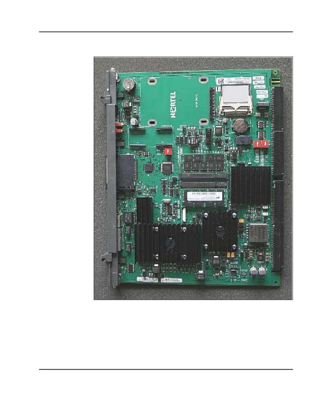
System components
Figure 1
CS 1000E CP PM Call Server
NN43041-310
Standard 01.11
October 2008
System components Page 45 of 466
Figure 2
CS 1000E CP PM Call Server (side view)
Choosing the cabinet and slot location for the CP PM card
An MG 1000E performs functions under the control of the CS 1000E Core
CP PM Call Server. Traditionally, in CS 1000 Release 4.5, this core CP PM
Call Server was a CP PII or CP PIV processor in its own Call Server chassis.
Communication Server 1000E Installation and Commissioning
Page 46 of 466
System components
For CS 1000 Release 5.0, the CP PM call server processor sits in one of the
slots in the MG1000E chassis.
The CP PM Call Server processor connects to the MG 1000E Media Gateway
Controllers via Ethernet and therefore does not require backplane
connectivity (other than power and slot ID). The following rules apply to the
preferential placement of the CP PM call server in the MG 1000E:
•
The CP PM call server processor must not be installed in slot 0 of any
MG 1000E. This slot is reserved for the MG 1000E shelf controller card
(the MGC or the SSC).
•
To allow for ease of cabling, the CP PM call server processor can be
installed in slot 1 next to the MGC or the SSC. The CP PM signaling
server can be placed in slot 2.
•
If utilizing the Campus Redundancy call server redundancy option, place
the two CP PM call servers in separate MG 1000E cabinets to allow for
increased survivability.
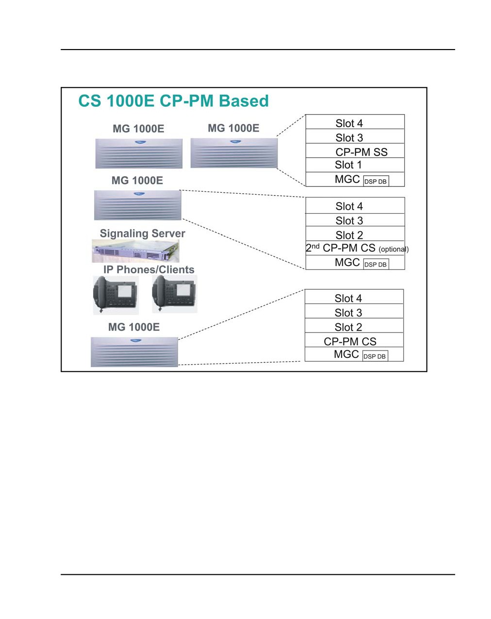
Figure 3 on page 47 shows a CS 1000E CP PM Call Server system overview.
NN43041-310
Standard 01.11
October 2008
System components Page 47 of 466
Figure 3
CS 1000E CP PM Call Server system overview
CP-PM Faceplate Components
The following section details the CP PM faceplate. Refer to Figure 4 on
page 50.
Status LED
•
Red: Hardware /BIOS
•
Flashing Red: Bootrom and OS (before Sysload Phase1)
•
Yellow: During Sysload Phase1
•
Flashing Yellow: During Sysload Phase2
Communication Server 1000E Installation and Commissioning
Page 48 of 466
System components
•
Green: Normal Operation
•
Flashing Green: SL1 Loading (on Active Core only)
•
Off No Power
Call Server Redundancy LED
•
Green: Redundant Mode, Active
•
Flashing Green: Split Mode, Active
•
Yellow: Redundant Mode, Standby
•
Flashing Yellow: Split Mode, Standby
•
Red: Single Mode
•
Off Not implemented
Ethernet Interface LEDs
ELAN RJ45 left:
•
Green: Link Up
•
Blink Green: Link Up & Activity
•
Off: No Link
ELAN RJ45 right:
•
Off: 10 Mbps
•
Yellow: 100 Mbps
HSP RJ45 left
•
Green: Link Up
•
Blink Green: Link Up & Activity
•
Off: No Link
NN43041-310
Standard 01.11
October 2008
System components Page 49 of 466
HSP RJ45 right
•
Off: 10 Mbps
•
Yellow: 100 Mbps
•
Green: 1000 Mbps
Compact Flash/ Hard Disk LEDs
•
CF - Flashing Green shows activity on RMD
•
HD/CF - Flashing Green shows activity on FMD (or HD for CP PM
Signaling Server)
Faceplate Push Buttons
•
RST: Cold Start / SysLoad
•
INI: Warm Start / INI
Communication Server 1000E Installation and Commissioning
Page 50 of 466
System components
Figure 4
CS 1000E CP PM Call Server
CP PM CS Serial Data Interface (SDI)
The CP PM Call Server features two standard RS232 DTE serial ports, port 0
and port 1. These ports are accessible through a cable that attaches to the
chassis or cabinet MDF port.
NN43041-310
Standard 01.11
October 2008
System components Page 51 of 466
The TTY Settings are:
•
Baud Rate: 9600
•
Data bit: 8
•
Stop bit: 1
•
Parity: None
•
Flow Control: None
CP PM Call Server Switch Settings
The CP PM Call Server switch S5 must be set to position 1 to indicate that a
CF card is used for the FMD.
The CP-PM Signaling Server switch S5 must be set to position 2 to indicate
that a hard disk is used for the FMD.
CP PM Call Server software
The CP PM Call Server software features the following enhancements for
CS 1000 Release 5.0:
•
software is large-system based
•
uses the same machine type (711) as CP PII and CP PIV
•
new system type (4021)
•
new High Availability package (410)
•
new menus for setting the Side, Loop and Shelf information. The Loop
and Shelf refer to the IPMG Loop and Shelf where the CP PM CS is
located.
Communication Server 1000E Installation and Commissioning
Page 52 of 466
System components
IMPORTANT!
The RMD used for installation must be created
specifically for CP PM using the mkbootrmd utility
provided in the CP PM Call Server install zip file. An RMD
created using the CP PIV mkbootrmd utility will not work
on a CP PM Call Server installation. CP PM hardware
requires different bootrom.sys and nvram.sys files than
CP PIV due to the differences in the processor chipset
used on the two platforms.
CP PM Call Server Customer Database Transfer
All CP PII databases must be copied from floppy disk to CF card using the
existing Database Media Converter tool.
CP PM Call Server Keycode
Keycode files reside in /keycode directory and have different names but must
have the same extension ‘.kcd’. The maximum keycode file name length
including the extension is 25 characters. The following feature packages are
required:
•
368 CPP_CNI CP Pentium Backplane for Intel Machine
•
402 SOFT_SWITCH
•
403 IPMG
•
390 SBO Branch Office
•
410 HIGH_AVAIL High Availability
Signaling Server
Multiple hardware versions of the Signaling Server are introduced for
Release 5.0:
•
1U signaling servers
•
CP PM Signaling Server
The existing ISP1100 Signaling Server is also supported for Release 5.0.
NN43041-310
Standard 01.11
October 2008
System components Page 53 of 466
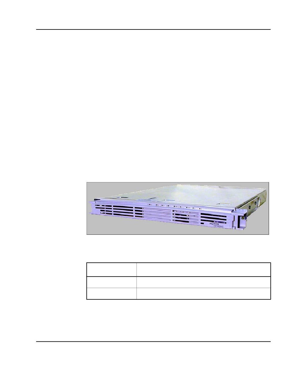
The ISP1100 Signaling Server, as shown in Figure 5 and described in Table
2, provides signaling interfaces to the network using software components
that run on a real-time operating system. You can install ISP1100 Signaling
Servers in a load-sharing redundant configuration for higher scalability and
reliability.
The ISP1100 Signaling Server is equipped with several software
components:
•
IP Phone Terminal Proxy Server (TPS)
•
H.323 Signaling Gateway (virtual trunk)
•
H.323 Gatekeeper
•
SIP
•
Network Routing Service
•
Element Manager web server
Figure 5
ISP1100 Signaling Server
Table 2
ISP1100 Signaling Server profile (Part 1 of 3)
Property
Description
Order Code
• NTDU27
Height
•
1 U (1 U = 1 3/4 inch or 4.4 cm)
Communication Server 1000E Installation and Commissioning
Page 54 of 466
System components
Table 2
ISP1100 Signaling Server profile (Part 2 of 3)
Property
Description
Power
• Power status indicator (green LED) is located on
the unit’s faceplate.
• Power cord connector is located on the left-hand
corner on the back of the unit.
• Power On/Off switch is on the faceplate.
• Power supplies are factory installed and not
customer replaceable.
• Unit is AC powered (100-240 VAC); DC input is
not supported.
Cooling
• Forced air cooling with front-to-back air flow.
• The fan runs whenever the unit is on.
Card slots
• None
NN43041-310
Standard 01.11
October 2008
System components Page 55 of 466
Table 2
ISP1100 Signaling Server profile (Part 3 of 3)
Property
Description
Connectors
•
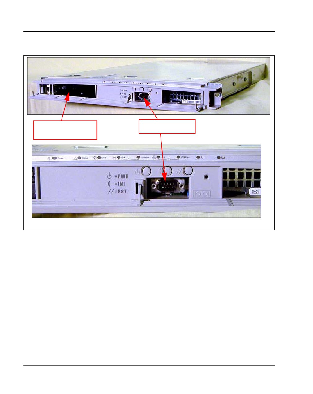
The DB-9 serial port, the CD-ROM and floppy
(front)
drives are located on the unit’s faceplate.
•
The DB-9 serial port can support a login session
for Command Line Interface (CLI) management.
•
See Figure 6 on page 56.
Connectors
•
The TLAN network interface (P2) connects the
(rear)
unit to a TLAN network interface on a Layer 2
Switch.
•
The ELAN network interface (P1) connects the
unit to an ELAN network interface on a Layer 2
Switch.
•
The DB-9 serial port can support a login session
for Command Line Interface (CLI) management.
•
There are three ports not used for any CS 1000E
system function. Do not plug any device into these
ports.
•
See Figure 7 on page 57.
CAUTION — Service Interruption
Do not connect maintenance terminals or modems to
the faceplate and I/O panel DB-9 male serial
maintenance port at the same time.
For detailed information about the ISP1100 Signaling Server, refer to
Signaling Server: Installation and Commissioning (NN43001-312).
Communication Server 1000E Installation and Commissioning
Page 56 of 466
System components
Figure 6
Connectors on the front of the ISP1100 Signaling Server
CD-ROM and floppy
Maintenance port
drives
NN43041-310
Standard 01.11
October 2008
System components Page 57 of 466
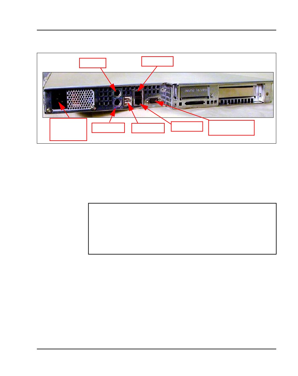
Figure 7
Connectors at the back of the ISP1100 Signaling Server
TLAN (P2)
not used
Universal AC
Maintenance/
power cord
not used
not used
ELAN (P1)
Admin port
connector
CP PM Signaling Server
The CP PM Signaling Server is in the form of a circuit card and comes in two
distinct models, NTDW61 and NTDW66. The NTDW61 model is designed
for use in a CS 1000E system and the NTDW66 model is designed for use in
a CS 1000M system.
IMPORTANT!
There are several switches on CP PM circuit cards. All switch settings
must be factory defaults except for the switch labelled “S5”. Switch S5
must be set to position 2 to support the internal hard drive used on the
CP PM Signaling Server circuit cards only.
Installation in a CS 1000E system
The NTDW61 model of the CP PM Signaling Server circuit card can be
inserted into any slot of an IPMG (MG 1000E or MG 1000B) or 11C cabinet
in a CS 1000E system, except slot 0. Slot 0 is reserved for an SSC or an MGC.
Communication Server 1000E Installation and Commissioning
Page 58 of 466
System components
Keying will prevent the NTDW61 circuit card from being inserted into this
slot.
CAUTION — Equipment Damage
Do not insert the NTDW61 model of the
CP PM Signaling Server circuit card into any
slot of an IPE cube. Doing so may cause
electrical shorts on adjacent circuit cards.
For detailed Signaling Server information, see “Installing a Signaling Server”
on page 173.
Media Gateway Controller
The Media Gateway Controller (MGC) Card is designed to replace the
gateway functionality of the SSC. It does not function as a Call Server,
requiring a separate Pentium based Call Server to handle call processing
requests. The MGC Card replaces the SSC in the CPU card position of an
Option 11C cabinet or an MG 1000E chassis, both for upgrades and new
installations. The MGC Card Supports legacy backplane interfaces (DS30x,
CEMUX). Key features include:
•
Increased Processing Power (10x over SSC)
•
Increased memory capacity (128Meg vs SSC 32Meg)
•
Standard Compact Flash used for permanent storage
•
2 PMC/PTMC Expansion Daughter board sites available
•
Embedded L2 Switch supports enhanced dual homing
•
Enables co-resident applications (Voice Gateway and Media Gateway
Controller)
DSP Daughterboards (optional)
Two optional DSP Daughterboards are introduced for the MGC Card, the
NTDW62AA 32-port DSP daughterboard and the NTDW64AA 96-port DSP
NN43041-310
Standard 01.11
October 2008
System components Page 59 of 466
daughterboard. These daughterboards provide DSP resources for connecting
IP and TDM devices, eliminating the need for installing Voice Gateway
Media Cards on the CS 1000E Media Gateways. However, Voice Gateway
Media Cards are still supported in CS 1000E.
MC32S Media Card
The MC32S is a 32-channel Voice Gateway Media Card that provides 32
Digital Signal Processor (DSP) ports to facilitate connectivity between IP and
TDM devices.
This media card replaces the existing 32-port Voice Gateway Media Card and
enables Secure Real Time Protocol (SRTP) to encrypt the IP media path to
and from all DSP channels on the MC32S. The MC32S also provides
improved echo performance over the existing media card.
Media Card
The Media Card, described in Table 3 and shown in Figure 8, connects an IP
and circuit-switched device using Digital Signal Processors (DSPs) for either
line or trunk applications. The DSPs, enabled by a Voice Gateway
application, performs media transcoding between IP voice packets and
circuit-switched devices.
The Media Card also provides echo cancellation and compression/
decompression of voice streams.
Table 3
Media Card profile (Part 1 of 2)
Property
Description
Product Code
• NTDU41DA
Media Card 32 Port IP Line 3.1/Voice Gateway
• NTDU41DB
Media Card 8 Port IP Line 3.1/Voice Gateway
Power
• Powered through a Media Gateway or a Media
Gateway Expander.
Communication Server 1000E Installation and Commissioning
Page 60 of 466
System components
Table 3
Media Card profile (Part 2 of 2)
Property
Description
Cooling
•
Provided by the Media Gateway or Media
Gateway Expander.
Connectors
•
The PC Card slot can be used to deliver software
(front)
or for additional storage.
•
The maintenance port provides access to the card
for OA&M purposes.
•
This port cannot be used for installation.
•
This port does not display bootup messages and
the user cannot change boot parameters using
this port.
Connectors
•
The Shielded 50-pin to Serial/ELAN/TLAN
(back)
adapter provides connections to the card through
the connector labelled Card 1, Card 2, Card 3, or
Card 4 that corresponds to the card location.
•
See Figure 28 on page 113.
•
Only this port can be used for installation.
•
The user can change boot parameters at the time
of bootup using this port.
NN43041-310
Standard 01.11
October 2008
System components Page 61 of 466
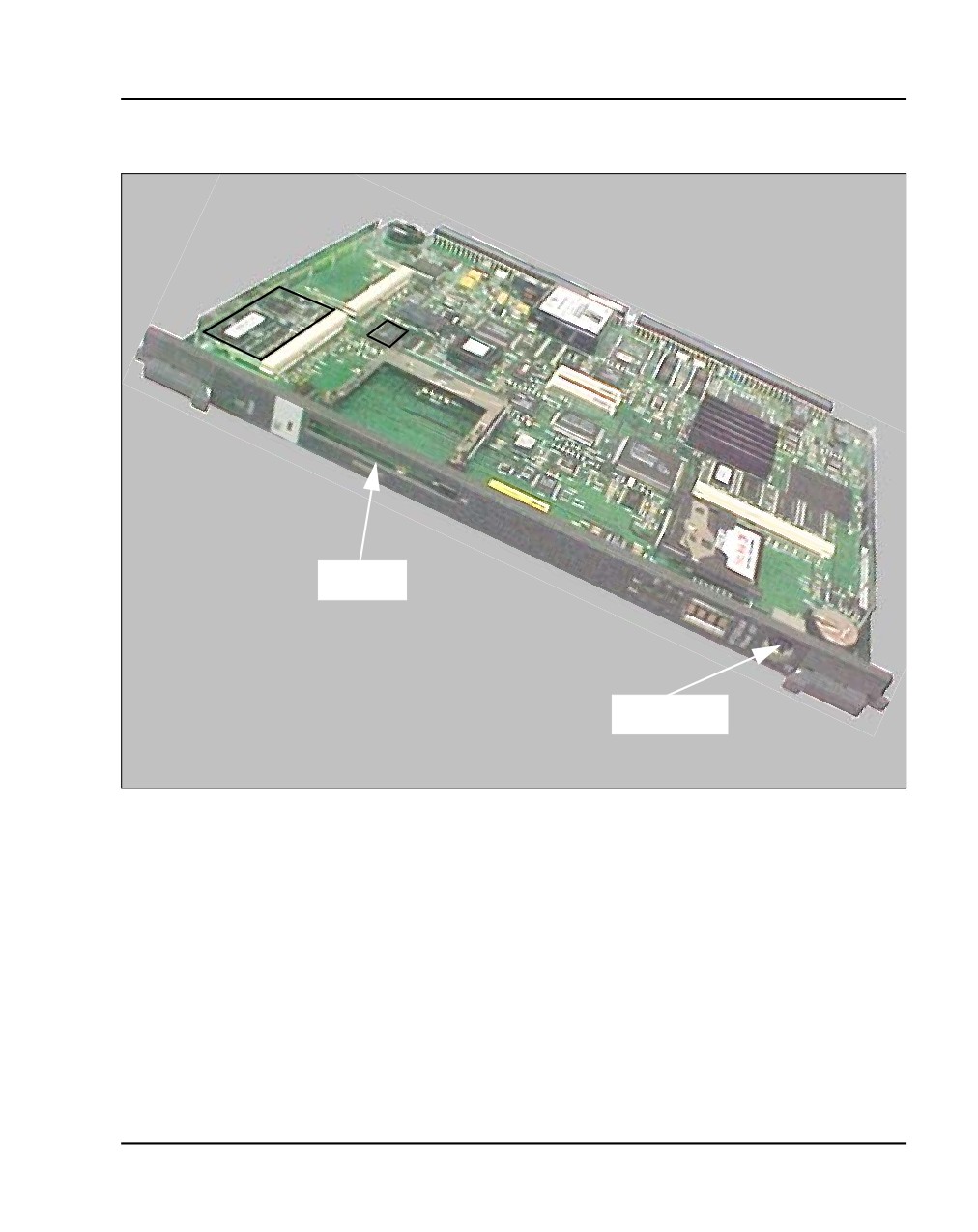
Figure 8
Media Card
PC Card
slot
Maintenance
port
Media Gateway
The media gateway is shown in Figure 9 on page 62 and described Table 4 on
page 62.
Communication Server 1000E Installation and Commissioning
Page 62 of 466
System components
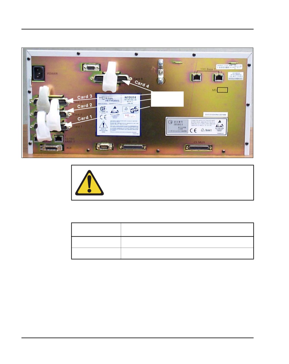
Figure 9
5-pair Cable Connectors on the Media Gateway
25-pair
connectors
CAUTION — Damage to Equipment
Do not block equipment ventilation openings.
Table 4
Media Gateway profile (Part 1 of 3)
Property
Description
Product Code
• NTDU14
Height
• less than 5 U (1 U = 1 3/4 inch or 4.4 cm)
NN43041-310
Standard 01.11
October 2008
System components Page 63 of 466
Table 4
Media Gateway profile (Part 2 of 3)
Property
Description
Power
•
Power status indicator (Nortel logo) is located on
the unit faceplate.
•
Power cord connector is located on the right rear
when viewed from the front.
•
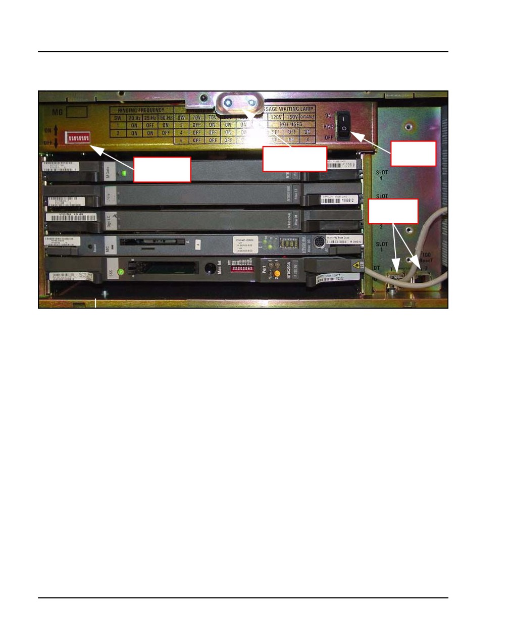
Power On/Off switch is located behind the
faceplate. See Figure 10 on page 66.
•
Power supplies are factory installed and not
customer replaceable.
•
Unit is AC powered (100-240 VAC); DC is not
supported.
Cooling
•
Forced air cooling with side-to-side air flow.
•
The fans are temperature controlled. The fans run
at a reduced speed at room temperature.
•
Ensure that equipment ventilation openings are
not blocked.
Card slots
•
Four usable universal card slots: 1 to 4.
•
Slot 0 is dedicated to the NTDK20FA or later SSC.
•
Slots 1 to 4 support:
— Digital Line cards (maximum four)
— Analog Line cards (maximum four)
— Analog Trunk cards (maximum four)
— Digital Trunk cards (maximum four)
— Media Cards (maximum four)
— Application cards (maximum four)
Communication Server 1000E Installation and Commissioning
Page 64 of 466
System components
Table 4
Media Gateway profile (Part 3 of 3)
Property
Description
Connectors
•
The 25-pair cable connectors at the back panel
(rear)
(see Figure 9 on page 62) provide access to the
cross-connect terminal (Main Distribution Frame).
•
The AUX port connects a Power Failure Transfer
Unit (PFTU) to the Media Gateway.
•
The Attachment Unit Interface (AUI) is used with
earlier version SSC which require a Media Access
Unit (MAU).
•
The SDI connector in the Media Gateway
provides an interface for a three-port SDI cable.
For MG 1000E this cable is not used unless
maintenance access using TTY0 is desired.
•
The DS-30X and CE-MUX cables connect the
Media Gateway to the Media Gateway Expander.
DIP switches
•
DIP switches are available to set the ringing
voltages, ringing frequencies, and message
waiting voltages. See Figure 10 on page 66.
NN43041-310
Standard 01.11
October 2008
System components Page 65 of 466
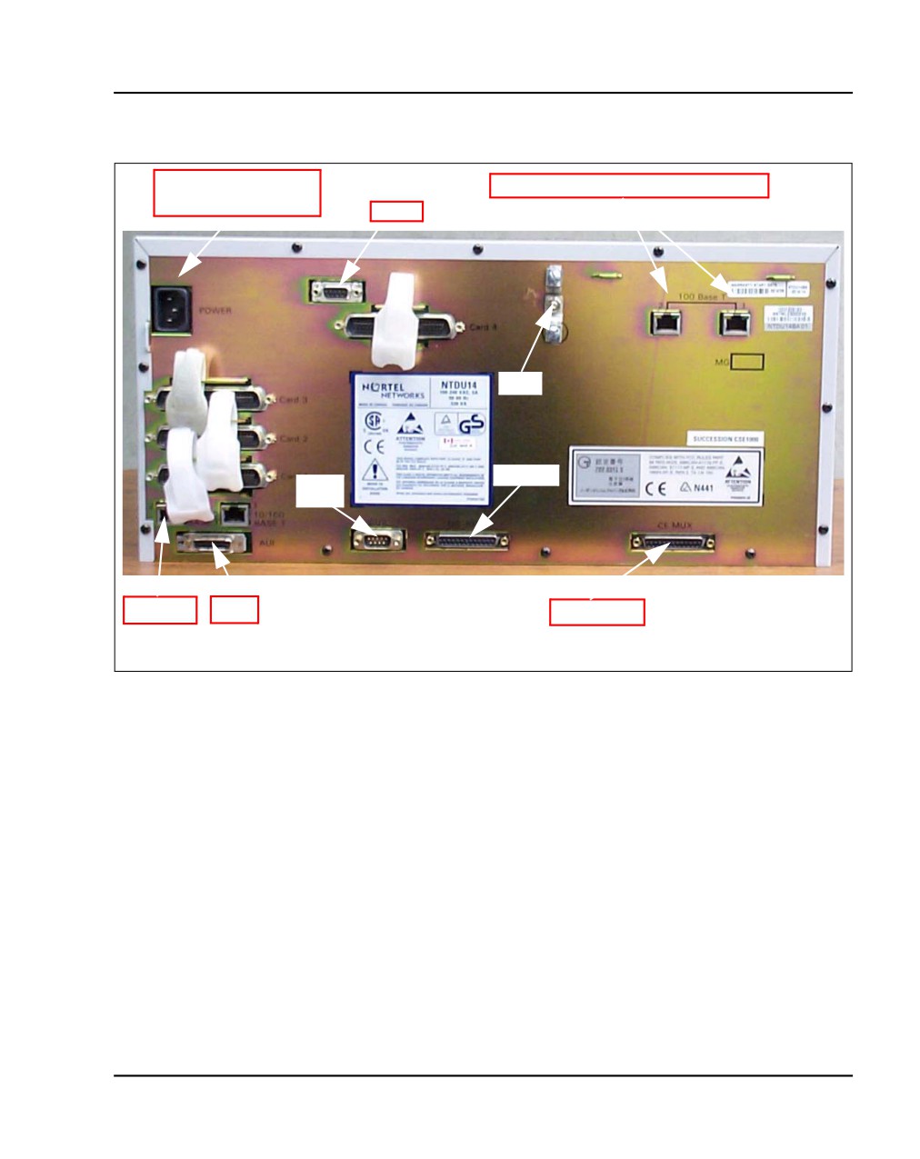
Figure 7
Connectors at the back of the Media Gateway
Universal AC power
Call Server to Media Gateway link
cord connector
AUX
2
1
GND
DS-30X
SDI
Port
Port 2
AUI
CE-MUX
Communication Server 1000E Installation and Commissioning
Page 66 of 466
System components
Figure 10
Front of the Media Gateway
Power
Power status
switch
DIP switch
indicators
settings
Bulkhead
connectors
NN43041-310
Standard 01.11
October 2008
System components Page 67 of 466
Media Gateway Expander
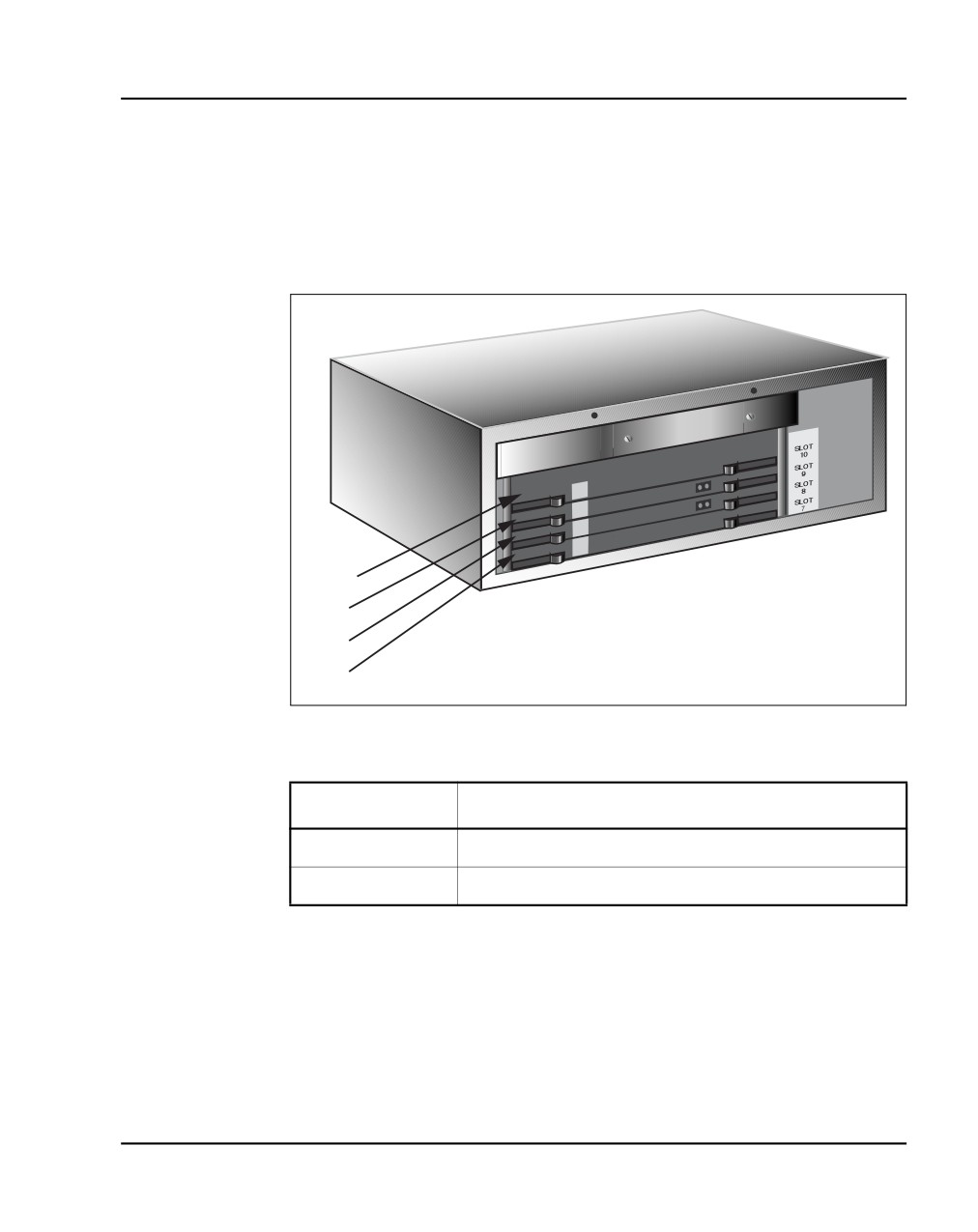
Figure 11 on page 67 shows the Media Gateway Expander and Table 5 on
page 67 describes the expander.
Figure 11
Media Gateway Expander
Slot 10
Slot 9
Slot 8
Slot 7
553-CSE9032
Table 5
Media Gateway Expander profile (Part 1 of 3)
Property
Description
Order Code
• NTDU15
Height
• less than 5 U (1 U = 1 3/4 inch or 4.4 cm)
Communication Server 1000E Installation and Commissioning
Page 68 of 466
System components
Table 5
Media Gateway Expander profile (Part 2 of 3)
Property
Description
Power
• Power status indicator (Nortel logo) is located on
the unit’s faceplate.
• Power cord connector is located on the right rear
when viewed from the front.
• Power On/Off switch is located behind the
faceplate. See Figure 10 on page 66.
• Power supplies are factory installed and not
customer replaceable.
• Unit is AC powered (100-240 VAC); DC is not
supported.
Cooling
• Forced air cooling with side-to-side air flow.
• The fans are temperature controlled. The fans run
at a reduced speed at room temperature.
• Ensure that equipment ventilation openings are
not blocked.
NN43041-310
Standard 01.11
October 2008
System components Page 69 of 466
Table 5
Media Gateway Expander profile (Part 3 of 3)
Property
Description
Card slots
•
Four usable universal card slots: 7 to 10. See
Figure 11 on page 67.
•
Logical slots 5 and 6 are not supported.
•
Slots 7 to 10 support:
— Analog Trunk cards (maximum four)
— Analog Line cards (maximum four)
— Digital Line cards (maximum four)
— Media Cards (maximum four)
— Application cards (maximum four)
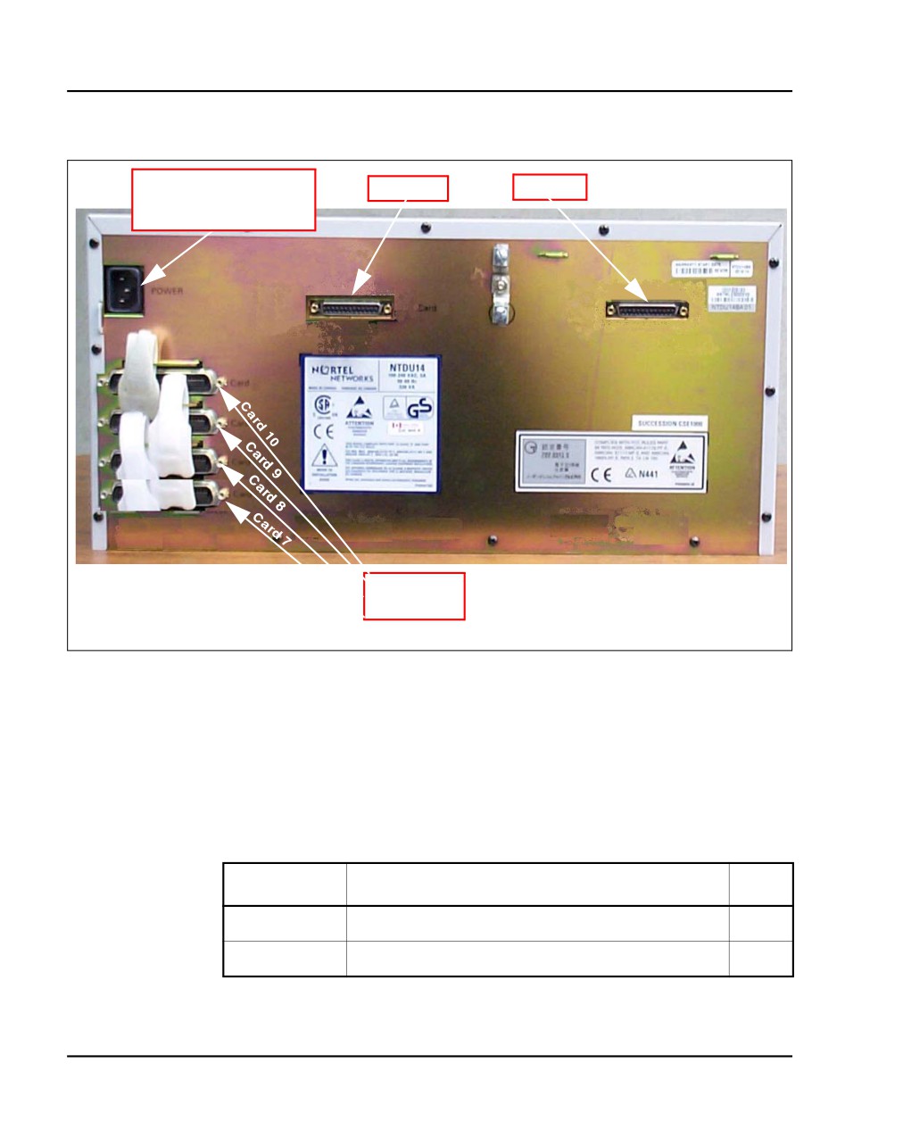
Connectors
•
The 25-pair cable connectors at the back of the
(rear)
unit (see Figure 12 on page 70) provide access to
the cross-connect terminal (Main Distribution
Frame). A Shielded 50-pin to Serial/ELAN/TLAN
adapter can also be used.
•
The AUX port connects a Power Failure Transfer
Unit (PFTU).
•
The DS-30X and CE-MUX cables connect the
Media Gateway to the Media Gateway Expander.
Communication Server 1000E Installation and Commissioning
Page 70 of 466
System components
Figure 12
Connectors at the back of the Media Gateway Expander
Universal AC power
DS-30X
CE-MUX
cord connector
25-pair
connectors
19-inch Rack Mount Kit
A 19-inch Rack Mount Kit (NTTK09AA) is available for mounting a Media
Gateway and Media Gateway Expander in a 19-inch rack. It is described in
Table 6 on page 70
Table 6
NTTK09AA installation
Order Code
Description
Qty
P0904844
Left Rack Mount Bracket
1
P0904845
Right Rack Mount Bracket
1
NN43041-310
Standard 01.11
October 2008
System components Page 71 of 466
Table 6
NTTK09AA installation
Order Code
Description
Qty
P0906672
Left Shelf Mounting Bracket U/O
1
P097F813
Screw, .216- 24 X .500 STL 289A
8
P0719943
Sems, Ext Tooth Washer Pan Head, CR
4
Type1A, 0.164- 32 X
P0906671
Right Shelf Mounting Bracket U/O
1
P0719587
Sems, Ext Tooth Washer Pan Head, CR Type
4
1A, 0.138- 3
BayStack 470 Switch
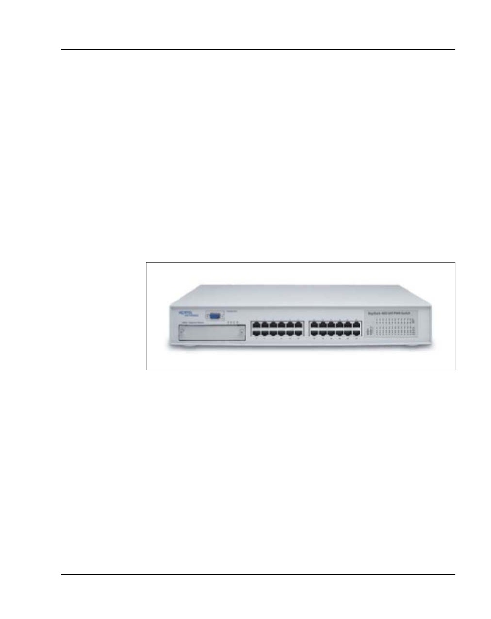
The BayStack 470 Switch, described in Table 7 on page 71, provides
policy-enabled networking features to optimize consistent performance and
behavior of network traffic. The Differentiated Services (DiffServ) network
architecture offers varied levels of service for different types of data traffic.
DiffServ lets you designate a specific level of performance on a per-packet
basis.
Table 7
BayStack 470 Switch profile (Part 1 of 2)
Property
Description
Height
•
1 U (1 U = 1 3/4 inch or 4.4 cm)
Power
• Power status LED indicator on the left side of the
unit’s faceplate.
• Power cord connector is located at the left rear of
the unit.
• Power supplies are factory installed and not
customer replaceable.
• Unit does not support DC input.
Communication Server 1000E Installation and Commissioning
Page 72 of 466
System components
Table 7
BayStack 470 Switch profile (Part 2 of 2)
Property
Description
Cooling
• Forced air cooling with side-to-side air flow.
• The three fans run whenever the unit is on.
Card slots
• None
Connectors
• Unit is DCE for serial port connection to PC;
(front)
requires null modem for Terminal Server
connection.
• Console port default settings: 9600 baud with 8
data bits, 1 stop bit, and no parity as the
communications format, with flow control set to
enabled.
•
10BaseT/100BaseTX RJ-45 (8-pin modular) port
connectors.
For additional information, refer to Using the BayStack 470 Switch.
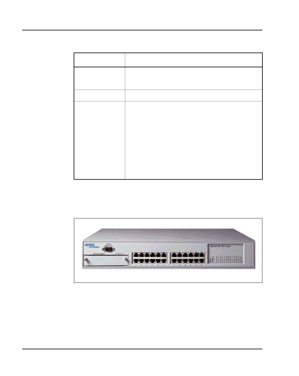
Figure 13
Ethernet switch
NN43041-310
Standard 01.11
October 2008
System components Page 73 of 466
A third-party data network switch can be used with the system. For more
information, refer to Converging the Data Network with VoIP
(NN43001-260).
BayStack 460 Layer 2 switch
The BayStack 460 Layer 2 switch, shown in Figure 14 on page 73, adds
power in addition to data communications over standard Category 5 LAN
drops for powering the IP Phones. The LAN power system eliminates the
need to connect each telephone to an AC power outlet saving in desktop
wiring and also allowing centralized UPSs for power backups. Using a Power
over LAN unit eliminates the need to use separate power transformers for
each IP Phone.
Figure 14
Power over LAN unit
MRV Terminal Server
The Terminal Server, described in Table 8 on page 74, provides the dedicated
rlogin service used to establish serial connection between a CS 1000E and
various serial devices. The IP-based Terminal Server provides standard serial
ports for applications that use a serial port interface. These applications
include billing systems that analyze Call Detail Recording (CDR) records,
Site Event Buffers (SEB) that track fault conditions, and various legacy
applications such as Property Management System (PMS) interface and
intercept Computer applications. In addition, serial ports are used to connect
maintenance terminals and modems for support staff.
Communication Server 1000E Installation and Commissioning
Page 74 of 466
System components
The Terminal Server is configured to automatically log in to the active Core
CP PM Call Server upon start-up. It always connects to the Active CPU IP
address.
The CS 1000E can configure up to 16 serial ports for applications within the
configuration Data Block. Ports can be configured by using:
•
login userid of "PTYnn" - TTY ports are specified where nn is the PTY
port number configured for a particular TTY within LD 17. If a "PTYnn"
userid is specified and that port is busy because of another login, an error
message will be produced (on the maintenance consoles, in the report
log, or as SNMP alarms).
•
no userid or the OTM userid - the highest available PTY port number is
selected
The Terminal Server has the following attributes:
•
support “rlogin” protocol on local access mode
•
support transparent, or binary mode, on “rlogin” connection
•
support port speed up to 115kbps
•
support auto rlogin connection and auto-retry after being disconnected
•
support BOOTP
•
support DHCP
•
rack mounted to a 19-inch rack
•
provide configurable username for each port
Table 8
MRV IR-8020M Terminal Server profile (Part 1 of 2)
Property
Description
Product Code
NTVW00AB
Height
•
1 U (1 U = 1 3/4 inch or 4.4 cm)
NN43041-310
Standard 01.11
October 2008
System components Page 75 of 466
Table 8
MRV IR-8020M Terminal Server profile (Part 2 of 2)
Property
Description
Power
• Power cord connector is located on the left-hand
corner on the unit’s backplane.
• Power supplies are factory installed and not
customer replaceable.
• Unit is AC powered (120 V AV @ 1.58 amps).
Cooling
• Forced air cooling with side-to-side air flow.
• The fans run at a single speed.
• Ensure that equipment ventilation openings are
not blocked.
Card slots
• None
Connectors
• Twenty console ports for modular RJ-45
connectors
• One RJ-45 (10BaseT) network interface
19-inch rack
All CS 1000E system components are mounted in a customer-supplied
19-inch rack. Ground the rack and equipment to the NTDU6201 Ground Bar.
System cables
Table 9 on page 76 lists the cables required with the CS 1000E system.
The base marketing package NTHU53AA provides an NTRC17 crossover
cable to connect the LAN2 ports of the two core CP PM Call Servers. It also
contains two MRV Terminal Server cables (NTDU6302) to connect from
COM port 1 of both core CP PM Call Servers to the MRV Terminal Server.
Note: Order the proper power cord for your region.
Communication Server 1000E Installation and Commissioning
Page 76 of 466
System components
Table 9
CS 1000E cables (Part 1 of 2)
Cables &
Component Descriptions
Cable Kits
Accessories
Quantity
Qty of 2 MRV Terminal Server cables for connecting
NTDU6302
2
COM port 1 of the CP PM Call Server to the Terminal
Server
HS cross-over cable used to connect the two call
NTRC17BA
1
processors for redundancy.
Media Gateway/Media Gateway Expander
Media Gateway cable kit
NTDU25BA
PC Maintenance Cable for accessing media card from
NTAG81CA
1
the faceplate
AUX cable for Power Failure Transfer if required
NTAK1104
1
25 pin M-F adapter, can be used with the NTBK48AA
A0601396
1
cable for interconnecting to TTY ports
25 pin F-F adapter, can be used with the NTBK48AA
A0601397
1
cable for interconnecting to TTY ports
Wrist strap
A0783105
1
25 pin F-F Null modem adapter, can be used with the
A0378652
NTBK48AA cable for interconnecting to TTY ports
25 pin M-F Null modem adapter, can be used with the
A0381016
NTBK48AA cable for interconnecting to TTY ports
RJ45 ethernet cable, used to connect dual and single
NTDU0606
port 100BT daughter cards from the SSC to the Media
Gateway bulk head
Expansion cable kit
NTDK89AA
Expansion cable to connect the Media Gateway
NTDK95BB
2
DS-30 and CE-MUX to the Media Gateway Expander.
Disposable wrist strap
A0783105
1
NN43041-310
Standard 01.11
October 2008
System components Page 77 of 466
Table 9
CS 1000E cables (Part 2 of 2)
Cables &
Component Descriptions
Cable Kits
Accessories
Quantity
100BaseT Connection
Signaling Servers, Layer two switch (BS 470), Carrier
CAT5 Cables
Cards, ELAN on Gateways
MRV Terminal Server
RJ45 to 9-pin female RS232, 25 feet long, for
NTVW01iX
connecting terminal equipment to the MRV Terminal
Server
Terminal server cable kit for interfacing with various
NTDU6303
terminal ports (that is, Signaling Server, Baystack or
Gateway using BK48 cable)
MRV Terminal Server cable for connecting various
NTDU6302
1
Terminal Equipment to the Terminal Server
9-pin male to 9-pin female Null Modem adapter for use
N0007485
1
where connecting to DCE connections
25 to 9-pin male adapter to interface with NTBK48AA
N0007488
1
cable if desired
Power cords
North American power Cord
NTTK14AB
UK power cord
NTTK18AB
Euro power cord
NTTK16AB
ANZ power cord
NTTK15AA
Swiss power cord
NTTK17AB
Denmark power cord
NTTK22AB
Communication Server 1000E Installation and Commissioning
Page 78 of 466
System components
Miscellaneous system components
Table 10 contains a list of miscellaneous items that can be used with the
CS 1000E system installation.
Table 10
Miscellaneous components
Order Code
Description
Purpose
QUA6A
Power Failure
To transfer trunk lines during a power failure
Transfer Unit
NTBK80BA
Ground bar
Ground Bar Option 11C for same room AC
Cabinets (1 per system and 2 or more cabinets)
NTDU6201
Ground bar
Ground Bar/LRE - Large
NT6D5304
Ground bar
Ground Bar/LRE - Small
NTAK92BA
External Protection
Protects up to four off-premises analog
Device
(500/2500-type) telephones
NT1R20BA
Extended Line card
Connects up to eight off-premises analog
Off-Premises
(500/2500-type) telephones
Uninterruptible Power Supply
Use an Uninterruptible Power Supply (UPS) to provide a backup power
supply for:
•
CS 1000E (Core CP PM Call Server 0 and Core CP PM Call Server 1)
•
Media Gateway
•
Media Gateway Expander
•
Signaling Server
•
MRV Terminal Server
•
BayStack 470-24T
•
BayStack 470-48T
•
BayStack 460 with Power over LAN
NN43041-310
Standard 01.11
October 2008
System components Page 79 of 466
A UPS provides a continuous AC power supply. Refer to Communication
Server 1000E: Planning and Engineering (NN43041-220) for calculating
power consumption requirements.
Install the UPS unit according to the manufacturer’s instructions.
Communication Server 1000E Installation and Commissioning
Page 80 of 466
System components
NN43041-310
Standard 01.11
October 2008
90
Page 81 of 466
Rack-mounting the components
Contents
This section contains information on the following topics:
Introduction
81
Lifting system components
82
Guidelines for component placement in a rack
83
Rack-mounting a Media Gateway or Media Gateway Expander
84
Rack-mounting a Terminal Server
90
Rack-mounting a BayStack 470 Switch
90
Rack-mounting a BayStack 460 Power over Ethernet unit
90
Introduction
All CS 1000E system components are installed in a customer-supplied,
19-inch rack. Also refer to the equipment layout plan and card slot assignment
plan for additional information.
Component air circulation is either from front to back or from side to side.
Therefore, components can be mounted immediately above or below an
installed component. The rack’s u pattern provides adequate clearance
between components. For example, a Media Gateway Expander could be
installed in the next 5u pattern of mounting holes below an already installed
Media Gateway. The Media Gateway Expander would be approximately
1/4 in from the Media Gateway.
Communication Server 1000E Installation and Commissioning
Page 82 of 466
Rack-mounting the components
Note: In the 5u pattern, a “u” is equal to 1.75 in. and includes three holes
spaced at 5/8 in. + 5/8 in. + 1/2 in.
Other data communications equipment can be installed in a rack with
CS 1000E system components.
IMPORTANT!
Ensure that the unit’s power cord is appropriate for the area’s electrical
service. Do not modify or use the supplied AC power cord if it is not the
correct type.
This chapter contains the following procedures:
•
Procedure 1: "Removing the cover" on page 84
•
Procedure 2: "Rack-mounting a Media Gateway or Media Gateway
Expander" on page 86
Lifting system components
Exercise care when lifting system components. If necessary, get assistance to
lift a component or install components in a rack. Table 11 on page 82 lists the
CS 1000E system components provided by Nortel and the weight of each
component. Consult the manufacturer’s documentation for the weight of
other components installed during the CS 1000E system installation.
Table 11
Weight of CS 1000E system components (Part 1 of 2)
Component
Lbs
Kg
ISP1100 Signaling Server
23
10.5
Media Gateway without cards
— with 4 cards
26
12
30
13.5
NN43041-310
Standard 01.11
October 2008
Rack-mounting the components Page 83 of 466
Table 11
Weight of CS 1000E system components (Part 2 of 2)
Component
Lbs
Kg
Media Gateway Expander
— without cards
26
12
— with 4 cards
30
13.5
BayStack 470 Switch
14.7
6.7
BayStack 460 Power over Ethernet Switch
12.76
5.8
MRV Terminal Server
11
5
Guidelines for component placement in a rack
When installing equipment, the Layer two switches should be in a central
location to allow for easy access of all LAN cabling. The Media Gateways
and Media Gateway Expanders must be mounted together vertically, and they
must be powered from the same power rail. Typical vertical power bars in
equipment racks are rated at 15/20 amps @ 120 volts. Ensure that the
equipment load does not exceed the power bar rating. Refer to
Communication Server 1000E: Planning and Engineering (NN43041-220)
for information on power consumption. Do not place redundant equipment on
the same electrical circuit.
There are no thermal concerns about equipment placement.
Note 1: Leave wall space for the cross-connect terminal.
Note 2: Position the rack so that you have access to both the front and
rear.
Communication Server 1000E Installation and Commissioning
Page 84 of 466
Rack-mounting the components
Rack-mounting a Media Gateway or
Media Gateway Expander
References to the Media Gateway in this section also apply to the Media
Gateway Expander. The Media Gateway Expander can be mounted either
above or below the Media Gateway.
The following items are required to mount each Media Gateway or Media
Gateway Expander in a 19-inch rack:
•
equipment layout plan
•
8 - #10-32 machine screws
•
19-Inch Rack Mount Kit (NTTK09)
The 19 Inch Rack Mount Kit (NTTK09) contains the following accessories:
•
1 - left guide bracket
•
1 - right guide bracket
•
1 - left ear bracket
•
1 - right ear bracket
•
4 - #8-32 machine screws
Follow Procedure 1 on page 84 to remove the cover on a Media Gateway or
a Media Gateway Expander.
Procedure 1
Removing the cover
1
If the cover lock latches are in their locked position:
a. Use a flat screwdriver to slide the icon away from the latch. Refer to
Figure 15 on page 85.
b. Slide both spring-loaded latches simultaneously down toward the
bottom of the Media Gateway, and pull forward. Then lift the cover
NN43041-310
Standard 01.11
October 2008
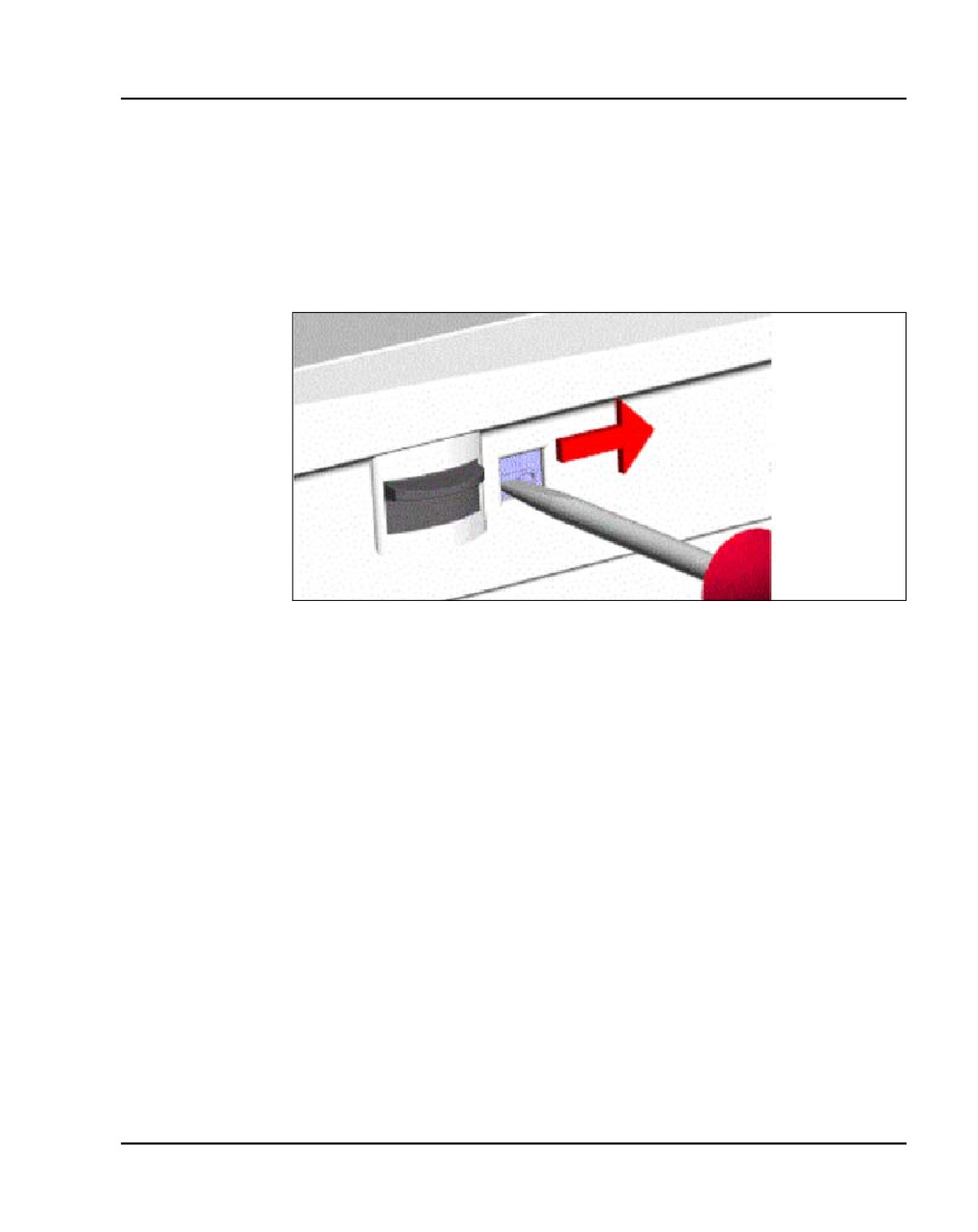
Rack-mounting the components Page 85 of 466
upward to remove it from the Media Gateway. Refer to Figure 16 on
page 86.
Note: The bottom of the front cover is supported by, but not secured to,
the Media Gateway. Do not drop it.
Figure 15
Unlock the latches
Communication Server 1000E Installation and Commissioning
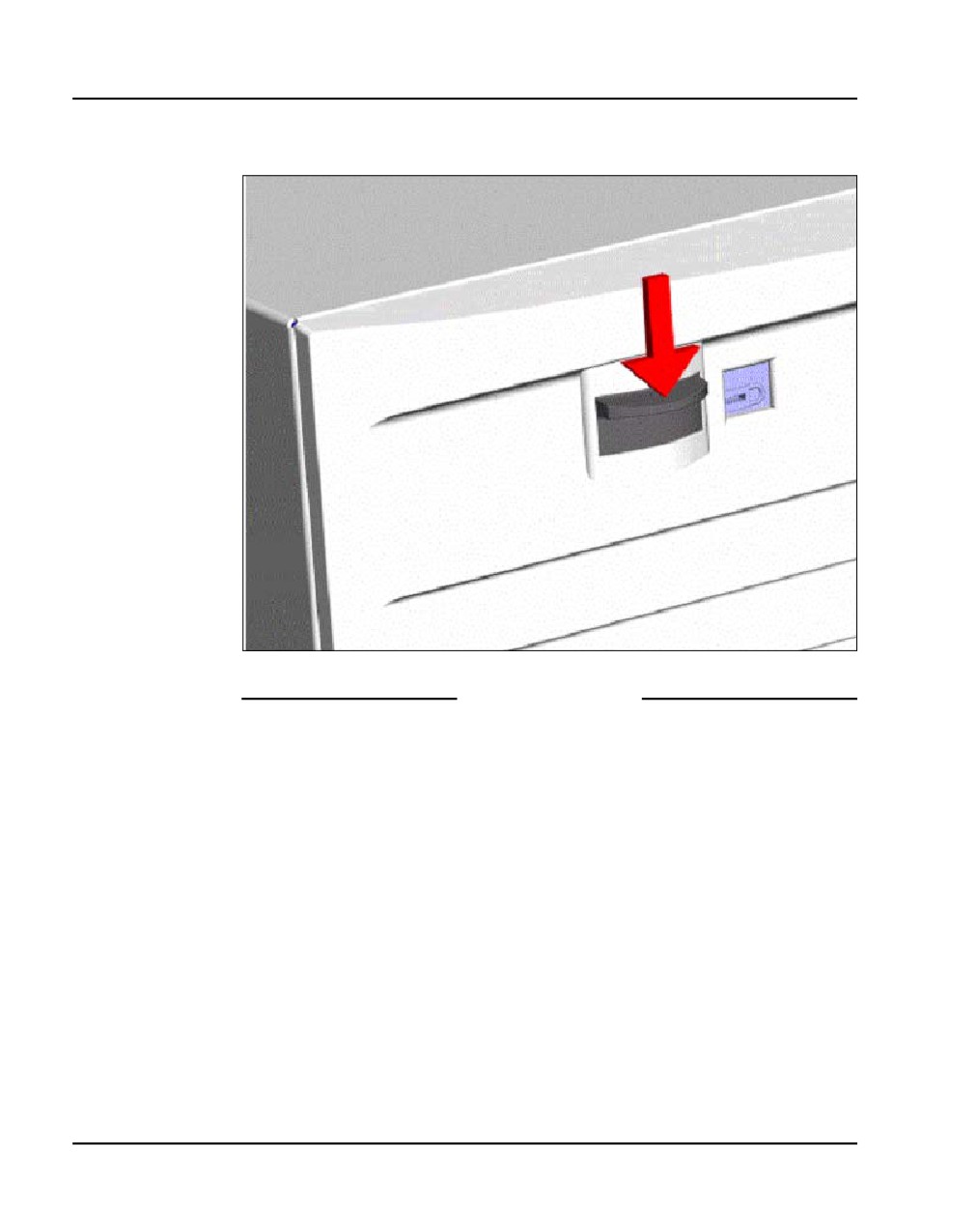
Page 86 of 466
Rack-mounting the components
Figure 16
Unlock the cover
End of Procedure
Procedure 2
Rack-mounting a Media Gateway or Media Gateway Expander
1
Fasten the right guide bracket to the right rack support.
a. Insert two #10-32 machine screws into the two middle slots in the
guide bracket and into the respective holes in the right rack support.
See Figure 17.
b. Fasten the screws.
NN43041-310
Standard 01.11
October 2008
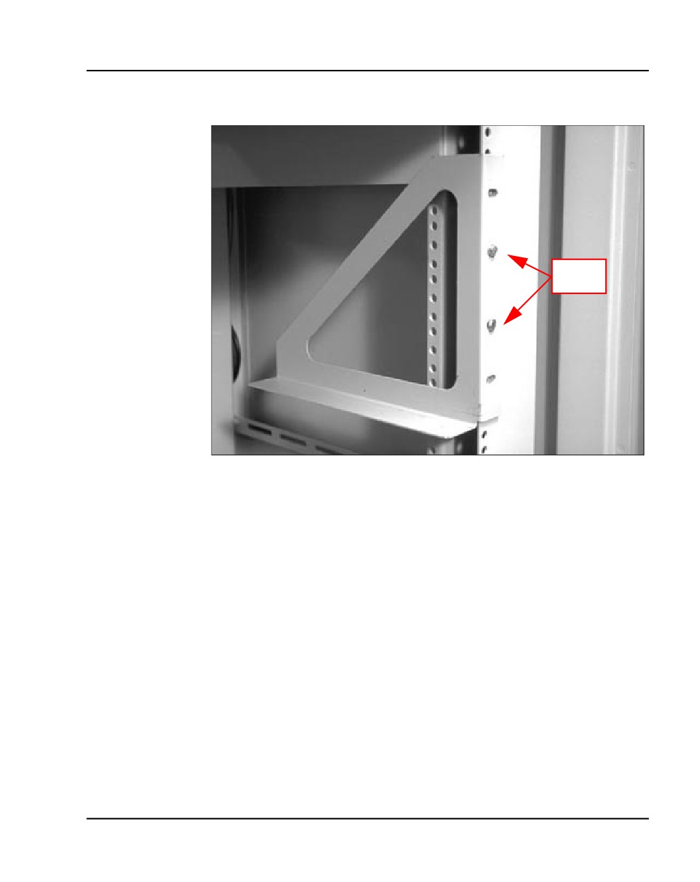
Rack-mounting the components Page 87 of 466
Figure 17
Guide bracket installed in a rack
#10-32
2
Fasten the left guide bracket to the left rack support.
a. Insert two #10-32 machine screws into the two middle slots in the
bracket and into the respective holes in the left rack support.
b. Fasten the screws.
3
Attach the right ear bracket (marked with an “R”) to the holes on the right
side of the Media Gateway.
a. Use two #8-32 machine screws. Position the ear bracket so that the
four holes on the bracket flange are nearer to the rear of the Media
Gateway.
Note: To determine the front of the bracket, locate the “R” on the bracket.
The “R” must be at the top of the bracket and face the front of the Media
Gateway (see Figure 18).
Communication Server 1000E Installation and Commissioning
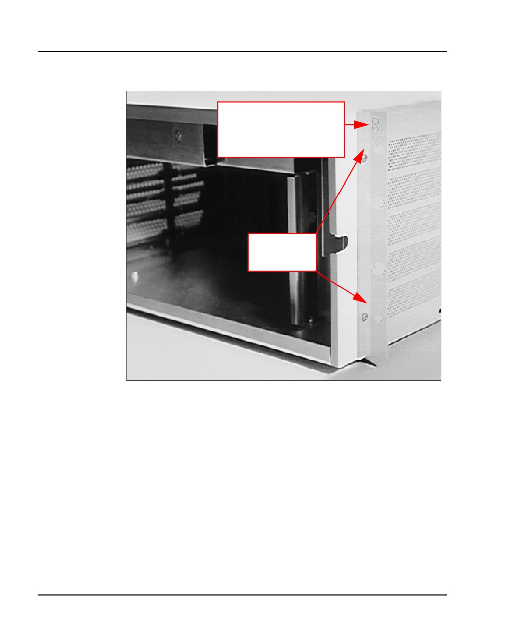
Page 88 of 466
Rack-mounting the components
Figure 18
Right ear bracket on a Media Gateway
Bracket flange marked
with an “R”. Attach this
ear bracket to the right-
hand side of the
Media Gateway.
Attach the
ear bracket to
these holes.
4
Attach the left ear bracket (marked with an “L”) to the holes on the left side
of the Media Gateway (near the front).
NN43041-310
Standard 01.11
October 2008
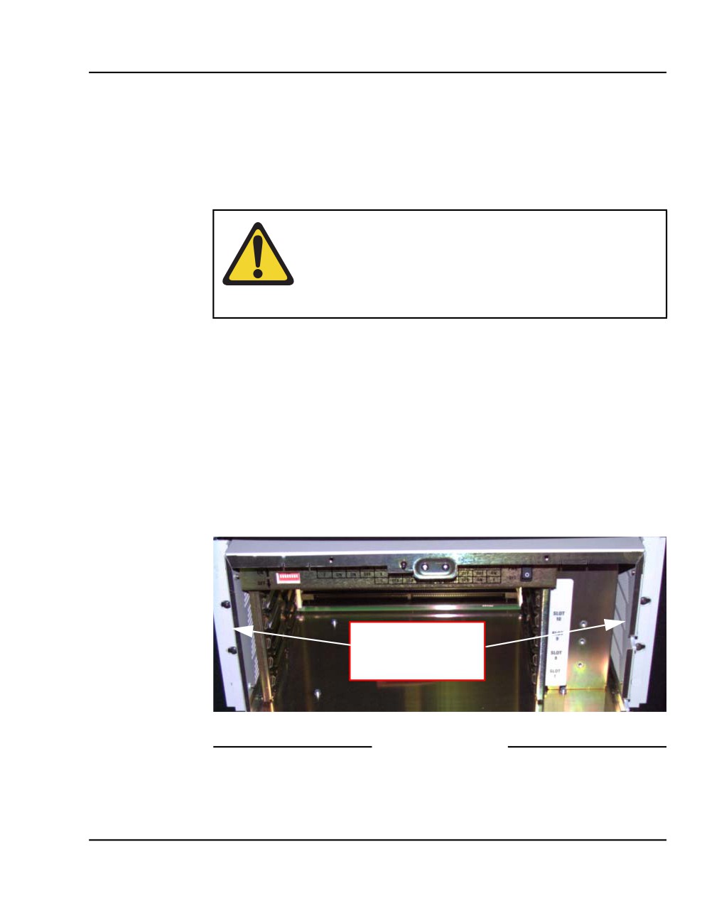
Rack-mounting the components Page 89 of 466
a. Use two #8-32 machine screws. Position the ear bracket so the four
holes on the bracket flange are closer to the rear of the Media
Gateway.
Note: To determine the front of the bracket, locate the “L” on the bracket.
The “L” must be at the top of the bracket and face the front of the Media
Gateway.
WARNING
A Media Gateway or a Media Gateway Expander each
weighs approximately 30 lb. (13.5 kg) with circuit cards
installed and 26 lb. (12 kg) without circuit cards installed.
If necessary, get assistance when lifting the equipment.
5
Place the Media Gateway on the guide brackets.
a. Carefully slide the Media Gateway into the rack until the ear brackets
come to rest against the rack support.
Note: Make sure that the rear of the Media Gateway is on the guide
brackets. See Figure 19 on page 89.
6
Use the four remaining #10-32 machine screws to fasten the Media
Gateway to the rack supports (two screws on each side).
Figure 19
Media Gateway installed in a rack
Use two screws on
each side to fasten
the Media Gateway
End of Procedure
Communication Server 1000E Installation and Commissioning
Page 90 of 466
Rack-mounting the components
Rack-mounting a Terminal Server
Follow the manufacturer’s instructions to rack-mount this equipment.
Rack-mounting a BayStack 470 Switch
Follow the manufacturer’s instructions to rack-mount this equipment.
Rack-mounting a BayStack 460 Power over Ethernet unit
Follow the manufacturer’s instructions to rack-mount this equipment.
NN43041-310
Standard 01.11
October 2008
100
Page 91 of 466
Installing system grounds
Contents
This section contains information on the following topics:
Introduction
91
Installing a ground bar
92
Grounding an ISP1100 Signaling Server
95
Grounding a Media Gateway powered by the same electrical panel . .
95
Grounding a Media Gateway powered by multiple electrical panels . .
97
Grounding a Media Gateway Expander
97
Grounding other rack-mounted components
98
Grounding equipment in the UK
100
Introduction
This chapter contains the following procedures:
•
Procedure 3: "Installing an NTBK80 Ground Bar" on page 93
•
Procedure 4: "Installing an NTDU6201 Ground Bar" on page 94
•
Procedure 5: "Grounding Media Gateways powered by the same
electrical panel" on page 96.
•
Procedure 6: "Grounding Media Gateways powered by multiple
electrical panels" on page 97
•
Procedure 7: "Grounding a Media Gateway Expander" on page 98
•
Procedure 8: "Grounding equipment in the UK" on page 100
Communication Server 1000E Installation and Commissioning
Page 92 of 466
Installing system grounds
Refer to your grounding plan for additional information.
WARNING
Correct grounding is very important. Failure to complete
the grounding procedures could result in a system that is
unsafe for the personnel using the equipment.
CAUTION — Service Interruption
If your system is not grounded correctly, it cannot be
protected from lightning or power surges, and it could be
subject to service interruptions. You must use insulated
ground wire for system grounding.
CAUTION — Service Interruption
To prevent ground loops, power all equipment from the
same dedicated electrical panel.
WARNING
For rack configurations, equipment must be powered
from the same electrical panel.
Installing a ground bar
Install the NTBK80 Ground Bar for up to six Media Gateways with their
Expander. Install the NTDU6201 Ground Bar for up to 35 ground
connections. Reference to ground bar in this NTP refers to either the NTBK80
or the NTDU6201 Ground Bar.
NN43041-310
Standard 01.11
October 2008
Installing system grounds
Page 93 of 466
Follow Procedure 3 to install a ground bar.
Procedure 3
Installing an NTBK80 Ground Bar
1
Place the ground bar near the equipment.
Note: The ground bar is a bridging point for ground wires from up to
six components.
2
Connect the ground bar to the ground bus in the AC electrical panel using
#6 AWG wire. See Table 12 on page 93 for region-specific grounding
requirements.
WARNING
A qualified technician or electrician must make the
connection in the AC electrical panel.
3
Place a tag marked DO NOT DISCONNECT on the ground wire at the
electrical panel.
4
Test the ground
Refer to Figure 20 on page 94 for the NTBK80 Ground Bar
Table 12
Region-specific grounding wire requirements
Region
Grounding wire requirements
Germany
#8 AWG (8.36 mm2) green/yellow
wire
Other regions in Europe
not smaller than #6 AWG
(13.3 mm2) at any point
UK
two green/yellow wires no thinner
than two 10 mm2
Communication Server 1000E Installation and Commissioning
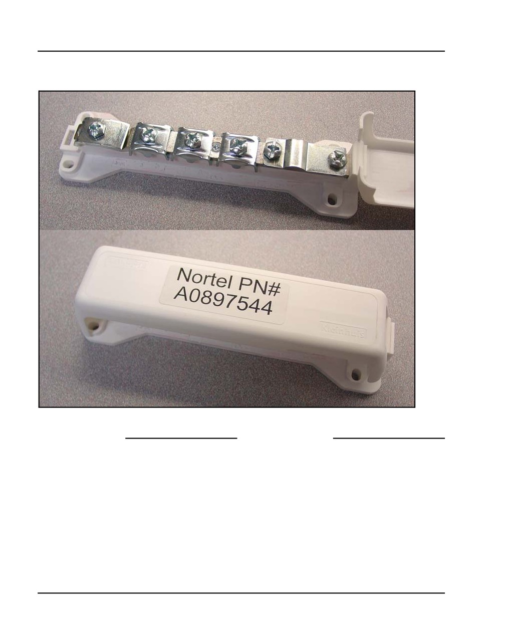
Page 94 of 466
Installing system grounds
Figure 20
NTBK80 Ground Bar
End of Procedure
Follow Procedure 4 to install an NTDU6201 Ground Bar.
Procedure 4
Installing an NTDU6201 Ground Bar
1
Place the NTDU6201 Ground Bar near the equipment.
Note: The ground bar is a bridging point for ground wires from up to
48 components.
NN43041-310
Standard 01.11
October 2008
Installing system grounds
Page 95 of 466
2
Connect the NTDU6201 Ground Bar to the ground bus in the AC electrical
panel, or to TGB for an ANSI/EIA/TIA 607 installation using #6 AWG wire.
See Table 12 on page 93 for region-specific grounding requirements.
WARNING
A qualified technician or electrician must make the
connection in the AC electrical panel.
3
Place a tag marked DO NOT DISCONNECT on the ground wire at the
electrical panel.
4
Test the ground.
End of Procedure
Grounding an ISP1100 Signaling Server
The ISP1100 Signaling Server is not connected to a ground bar. It is properly
grounded when:
•
the ISP1100 Signaling Server power cord is plugged into the rack’s AC
outlet. The rack’s AC outlet must be grounded to its dedicated electrical
panel. This is the preferred method.
•
the ISP1100 Signaling Server power cord is plugged into a wall AC
outlet. The ISP1100 Signaling Server is grounded outside of the rack
using the safety grounding conductor in the power cord. This method
ensures proper grounding only of the ISP1100 Signaling Server itself. It
does not provide grounding protection for other rack-mounted pieces of
equipment. Therefore, ensure that other devices in the rack are properly
grounded as required.
Grounding a Media Gateway powered by the
same electrical panel
Follow Procedure 5 to ground one or more Media Gateway powered by the
same electrical panel.
Communication Server 1000E Installation and Commissioning
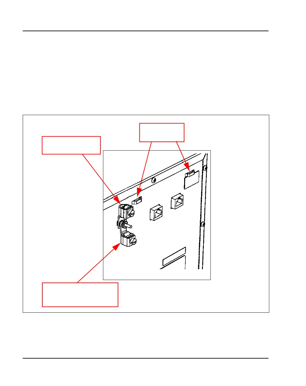
Page 96 of 466
Installing system grounds
Procedure 5
Grounding Media Gateways powered by the same electrical panel
1
Disconnect the AC power cord from the power outlet.
2
Install a #6 AWG ground wire from the ground lug, as shown in Figure 21
on page 96, at the back of the Media Gateway to the ground bar.
3
Place a DO NOT DISCONNECT tag on the ground wire.
Figure 21
Media Gateway and Media Gateway Expander ground lug location
Ground wire
tie wrap lug
Ground wire to
ground bar
Media Gateway to
Media Gateway Expander
ground lugs
NN43041-310
Standard 01.11
October 2008
Installing system grounds
Page 97 of 466
4
Test the ground.
End of Procedure
Grounding a Media Gateway powered by
multiple electrical panels
Follow Procedure 6 on page 97 to ground multiple Media Gateway that are
powered by multiple electrical panels.
Procedure 6
Grounding Media Gateways powered by multiple electrical panels
1
Disconnect the AC power cord from the power outlet.
2
Identify the electrical panel powering each component.
3
Install a ground bar for each electrical panel identified above.
Note: Each component must be grounded to the electrical panel that
provides the power to that component.
4
Install a #6 AWG ground wire from the ground lug on the rear of the Media
Gateway to the ground bar identified for that component’s power source.
5
Place a DO NOT DISCONNECT tag on the ground wire.
6
Test the ground.
End of Procedure
Grounding a Media Gateway Expander
The Media Gateway Expander and the Media Gateway are considered as the
same ground.
IMPORTANT!
Ground the Media Gateway Expander to the Media Gateway.
Communication Server 1000E Installation and Commissioning
Page 98 of 466
Installing system grounds
IMPORTANT!
Power each Media Gateway and Media Gateway Expander pair from
the same electrical panel.
Follow Procedure 7 to ground a Media Gateway Expander.
Procedure 7
Grounding a Media Gateway Expander
1
Disconnect the AC power cord from the power outlet.
2
Install a #6 AWG ground wire from the ground lug on the rear of the Media
Gateway Expander to the Media Gateway. See Figure 21 on page 96.
3
Place a DO NOT DISCONNECT tag on the ground wire.
4
Test the ground.
End of Procedure
Grounding other rack-mounted components
To ground multiple pieces of equipment in a rack, use a separate ground
connection from each piece of equipment to the ground bar. If a piece of data
communications equipment in a rack does not have a grounding lug then
ground the rack to the ground bar.
When the rack is grounded to the ground bar, the equipment is grounded
using the Single Point Grounding method, as shown in Figure 22 on page 99.
NN43041-310
Standard 01.11
October 2008
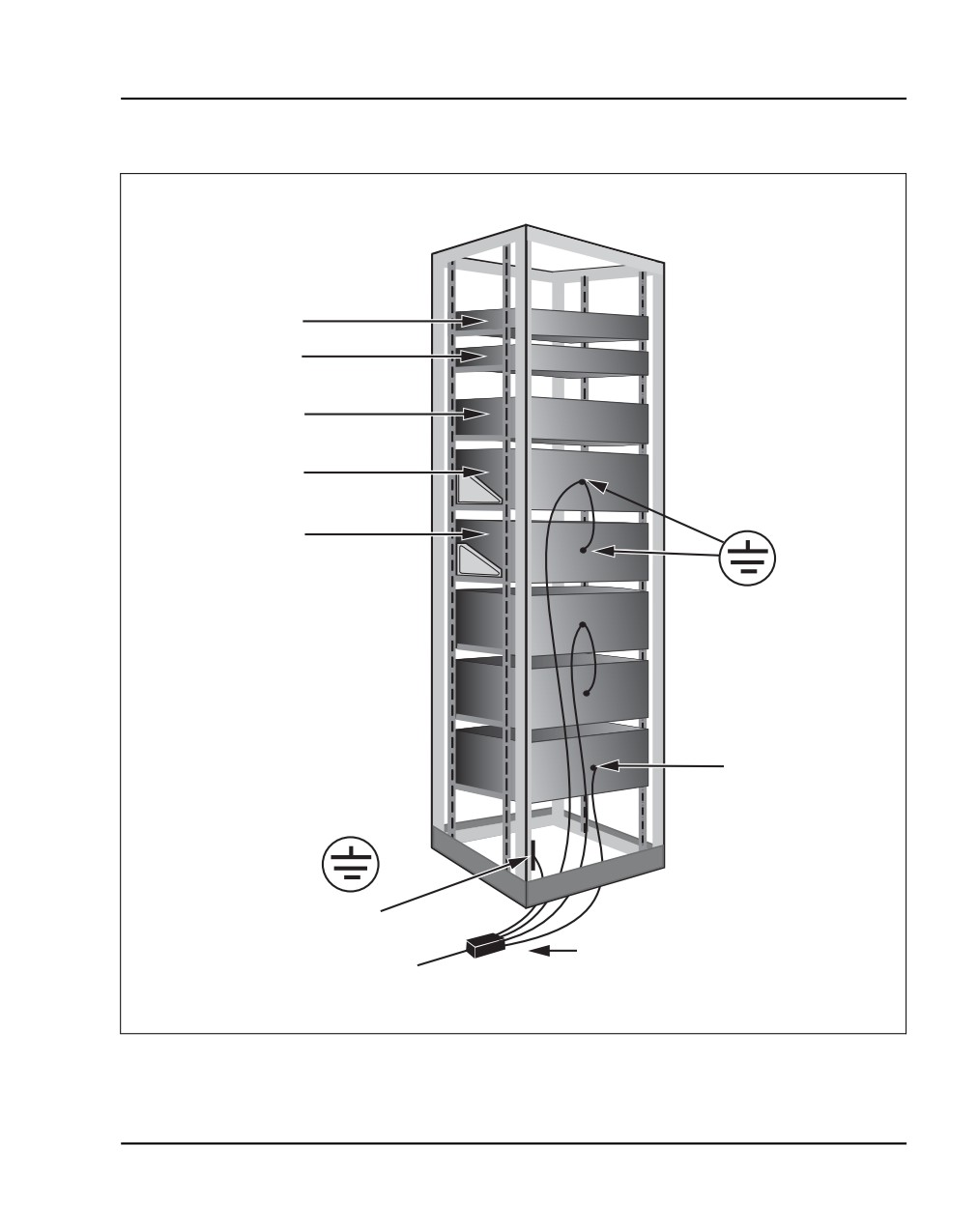
Installing system grounds
Page 99 of 466
Figure 22
Grounding multiple pieces of equipment in a rack
Terminal Server
Signaling Server
CS 1000E
Call Server
Media Gateway
Chassis
Grounding lug on
Media Gateway
back of chassis
Chassis Expansion
Other data
communications
equipment with
grounding lug
Rack
grounding
block
NTBK80 or NTDU6201 Ground Bar
553-CSE9027C
Communication Server 1000E Installation and Commissioning
Page 100 of 466
Installing system grounds
Grounding equipment in the UK
Follow Procedure 8 to ground equipment in the UK.
Procedure 8
Grounding equipment in the UK
1
Connect a protective and functional ground wire from the grounding strip
on the Krone Test Jack Frame to the ground at the building entry point.
Use a green/yellow wire no thinner than 10 mm2.
Consider each Media Gateway and Media Gateway Expander pair as one
ground.
2
Jumper the Media Gateway Expander ground to the Media Gateway
ground. See Figure 21 on page 96.
3
In each Media Gateway:
a. Connect a ground wire from the ground lug in the equipment to the
ground connection at the Test Jack Frame. Use a green/yellow wire
no thinner than 10 mm2.
b. Place a DO NOT DISCONNECT tag on the grounding wire.
c. Measure the resistance of the ground between the Krone Test Jack
Frame and the Media Gateway frame ground. The resistance must
not be more than 0.25 Ohm.
End of Procedure
NN43041-310
Standard 01.11
October 2008
//////////////////////////////////////////