F18. FLIGHT MANUAL (2008) - page 34
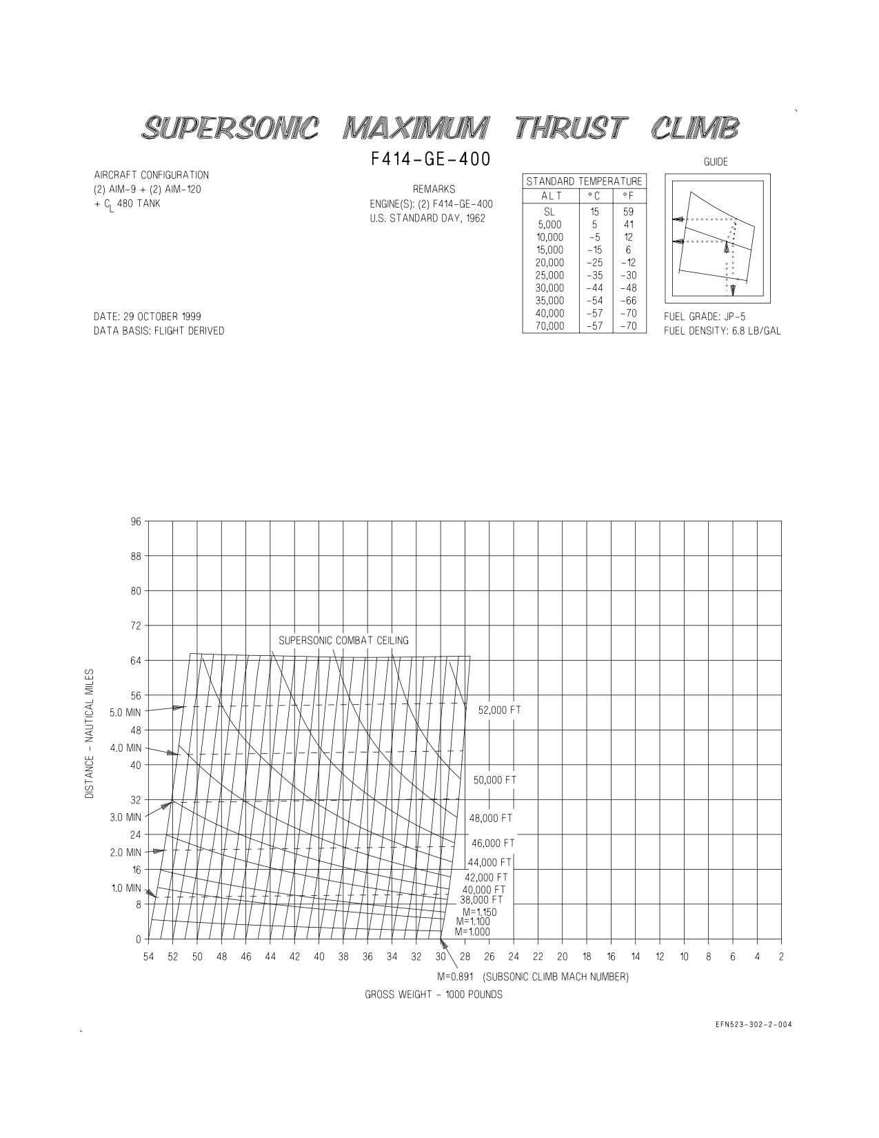
A1-F18EA-NFM-200
Figure 4-11. Supersonic Maximum Thrust Climb (Sheet 2 of 4)
XI-4-40
ORIGINAL
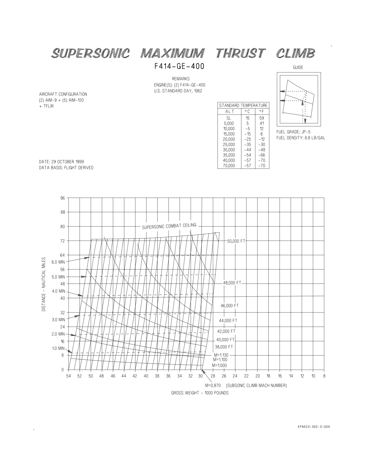
A1-F18EA-NFM-200
Figure 4-11. Supersonic Maximum Thrust Climb (Sheet 3 of 4)
XI-4-41
ORIGINAL
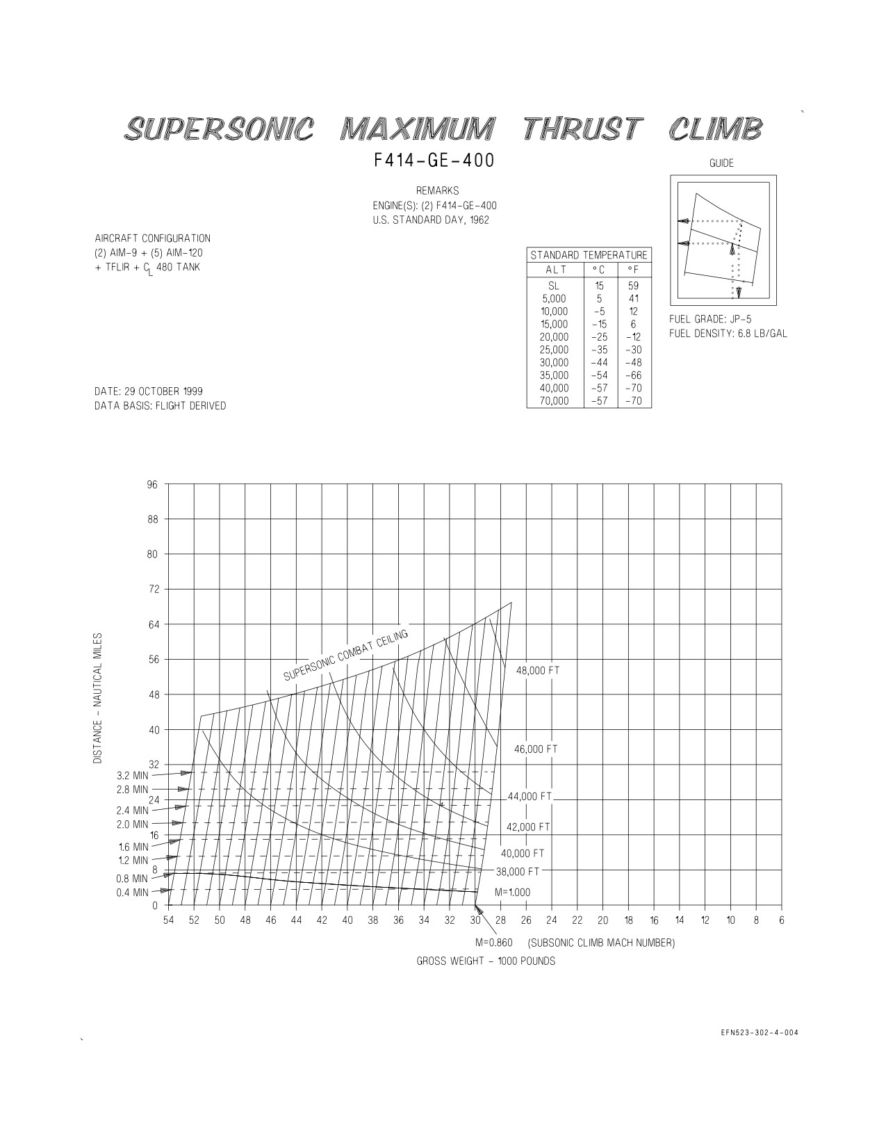
A1-F18EA-NFM-200
Figure 4-11. Supersonic Maximum Thrust Climb (Sheet 4 of 4)
XI-4-42
ORIGINAL
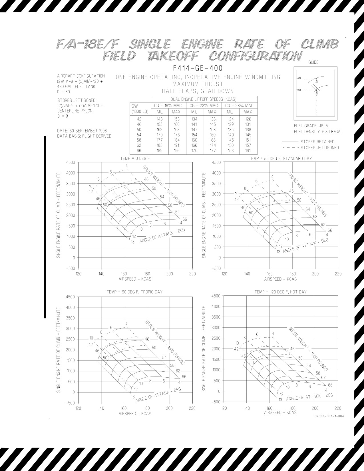
A1-F18EA-NFM-200
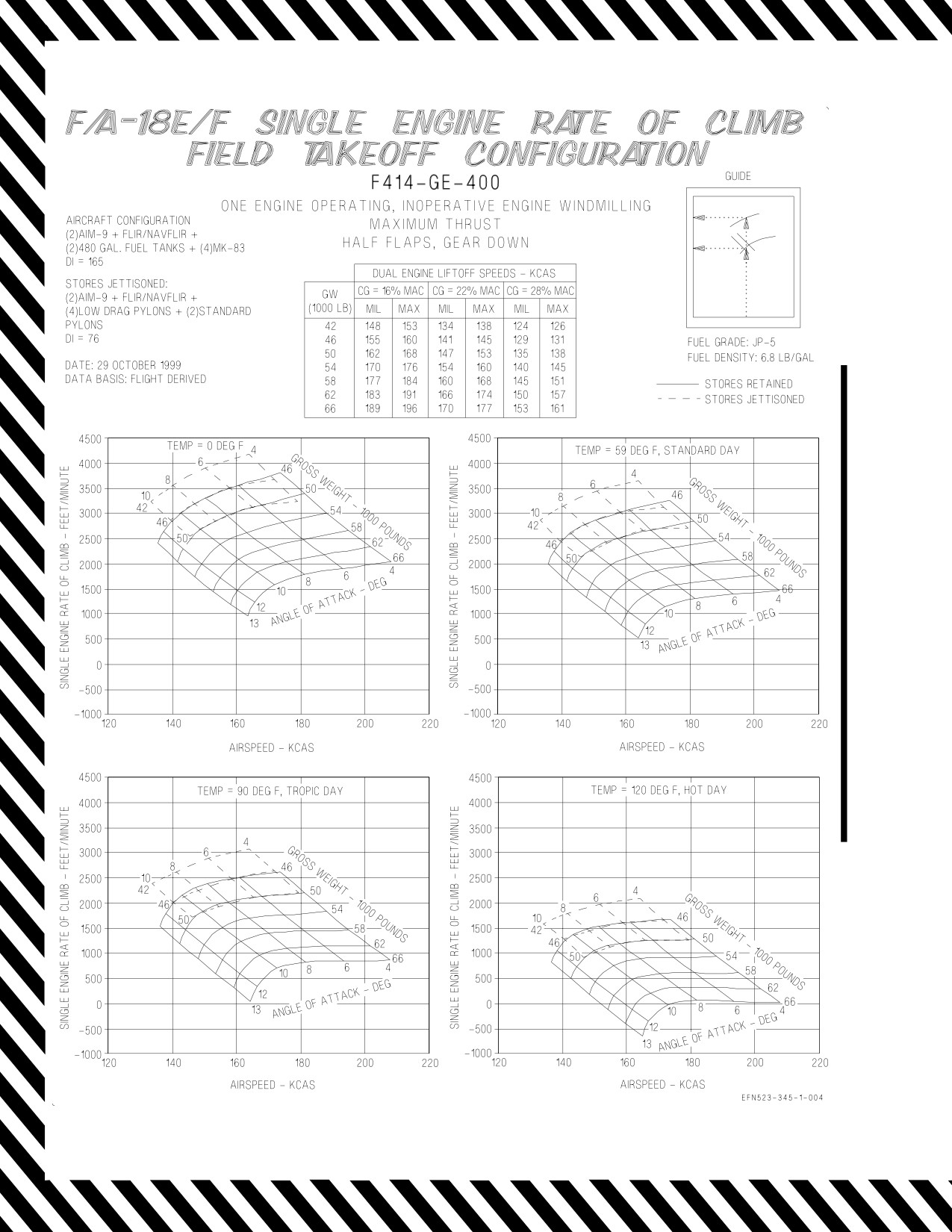
Figure 4-12. Single Engine Rate of Climb - Field Takeoff Configuration (Sheet 1 of 3)
XI-4-43
CHANGE 1
A1-F18EA-NFM-200
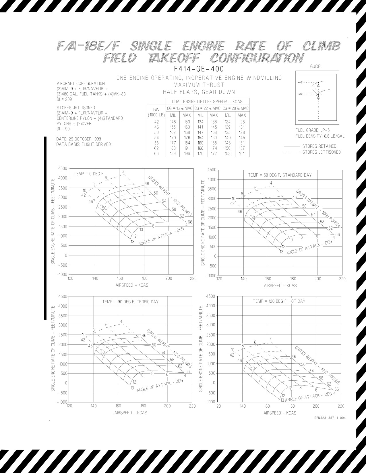
Figure 4-12. Single Engine Rate of Climb - Field Takeoff Configuration (Sheet 2 of 3)
XI-4-44
CHANGE 1
A1-F18EA-NFM-200
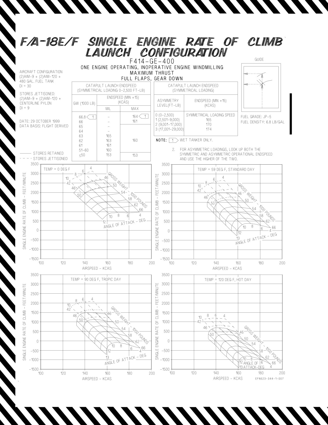
Figure 4-12. Single Engine Rate of Climb - Field Takeoff Configuration (Sheet 3 of 3)
XI-4-45
CHANGE 1
A1-F18EA-NFM-200
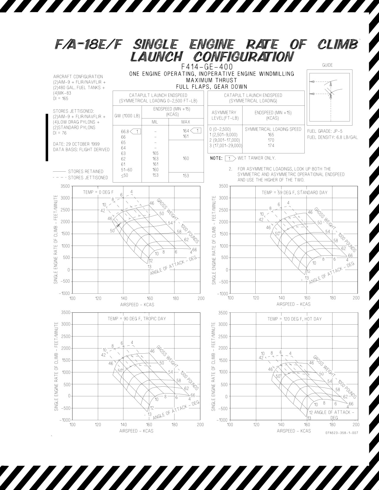
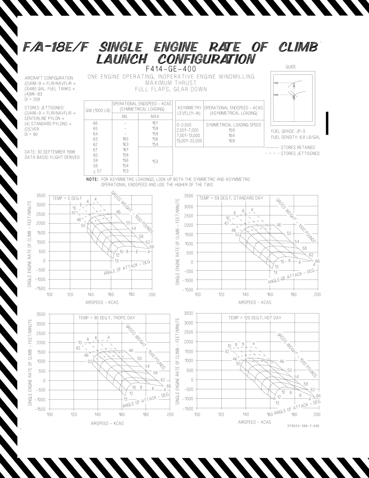
Figure 4-13. Single Engine Rate of Climb - Launch Configuration (Sheet 1 of 3)
XI-4-46
CHANGE 3
A1-F18EA-NFM-200
Figure 4-13. Single Engine Rate of Climb - Launch Configuration (Sheet 2 of 3)
XI-4-47
CHANGE 3
A1-F18EA-NFM-200
Figure 4-13. Single Engine Rate of Climb - Launch Configuration (Sheet 3 of 3)
XI-4-48
CHANGE 2
A1-F18EA-NFM-200
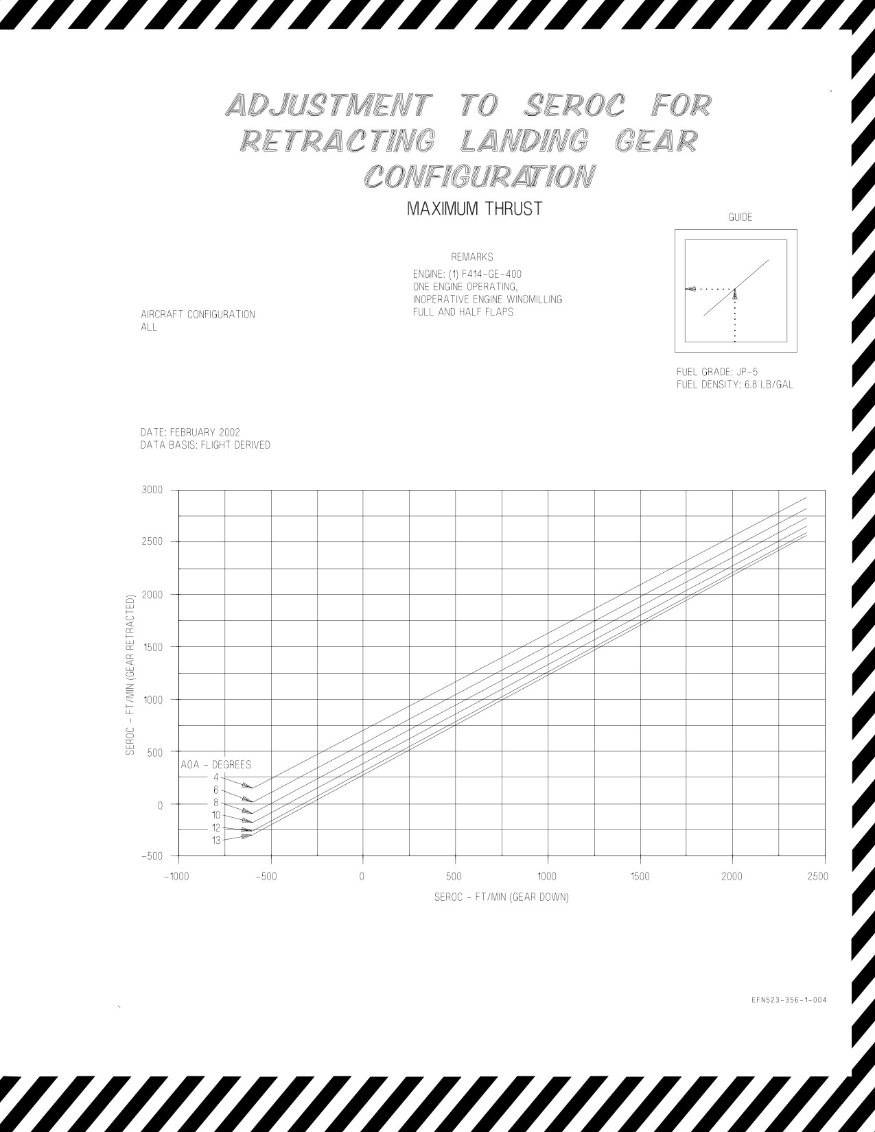
Figure 4-14. Adjustment to SEROC for Retracting Landing Gear Configuration
XI-4-49 (Reverse Blank)
ORIGINAL
A1-F18EA-NFM-200
CHAPTER 5
Range
F414-GE-400
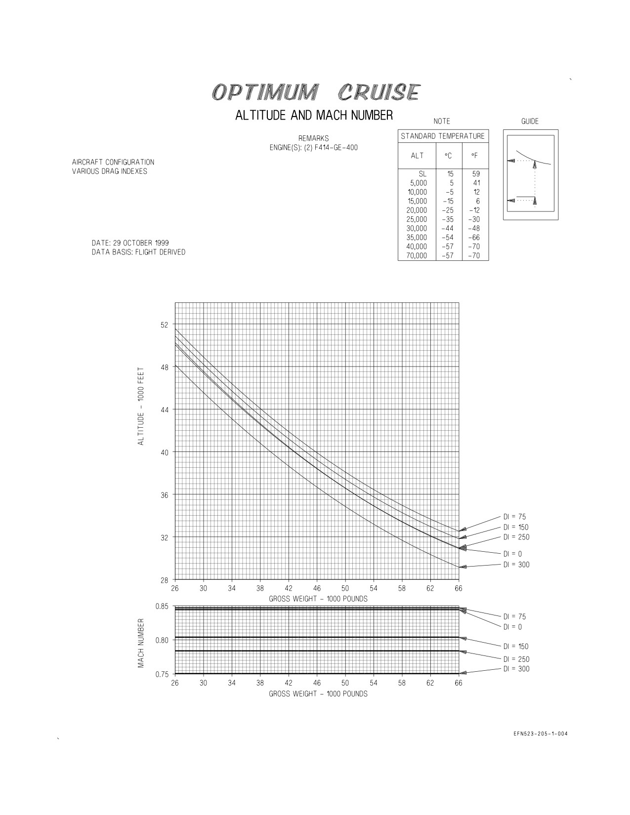
5.1 OPTIMUM CRUISE CHARTS
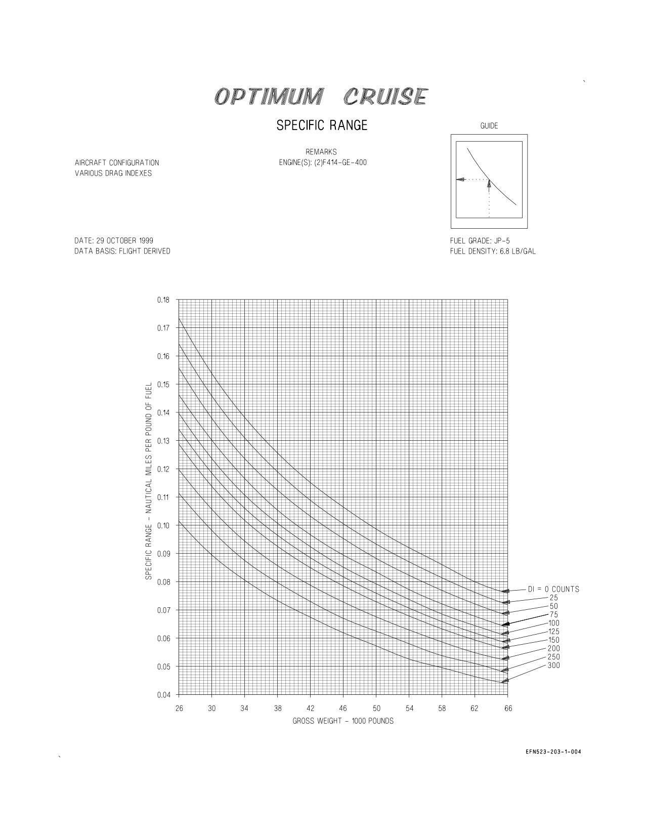
These charts (figure 5-1, sheets 1 and 2) present cruise data for two-engine operation. Sheet 1 depicts
cruise altitude and cruise Mach number for various gross weights and drag indexes. Sheet 2 depicts
specific range (nautical miles per pound of fuel (NMPP)) for various gross weights and drag indexes.
5.1.1 Use. To determine cruise altitude and Mach number, based on drag index and gross weight,
enter the chart with the applicable gross weight and project vertically up to intersect the appropriate
drag index curve. From the intersection of the drag index curve, project horizontally left and read Mach
number and specific range in nautical miles per pound.
To determine specific range based on drag index and gross weight, enter the chart with the
applicable gross weight and project vertically up to intersect the appropriate drag index curve. From
the intersection of the drag index curve, project horizontally left and read the specific range.
XI-5-1
ORIGINAL

A1-F18EA-NFM-200
5.1.2 Sample Problem. Two Engines Operating.
A. Gross weight
46,000 Lb.
B. Drag index
75
C. Mach number
0.847
D. Optimum cruise altitude
39,800 Ft.
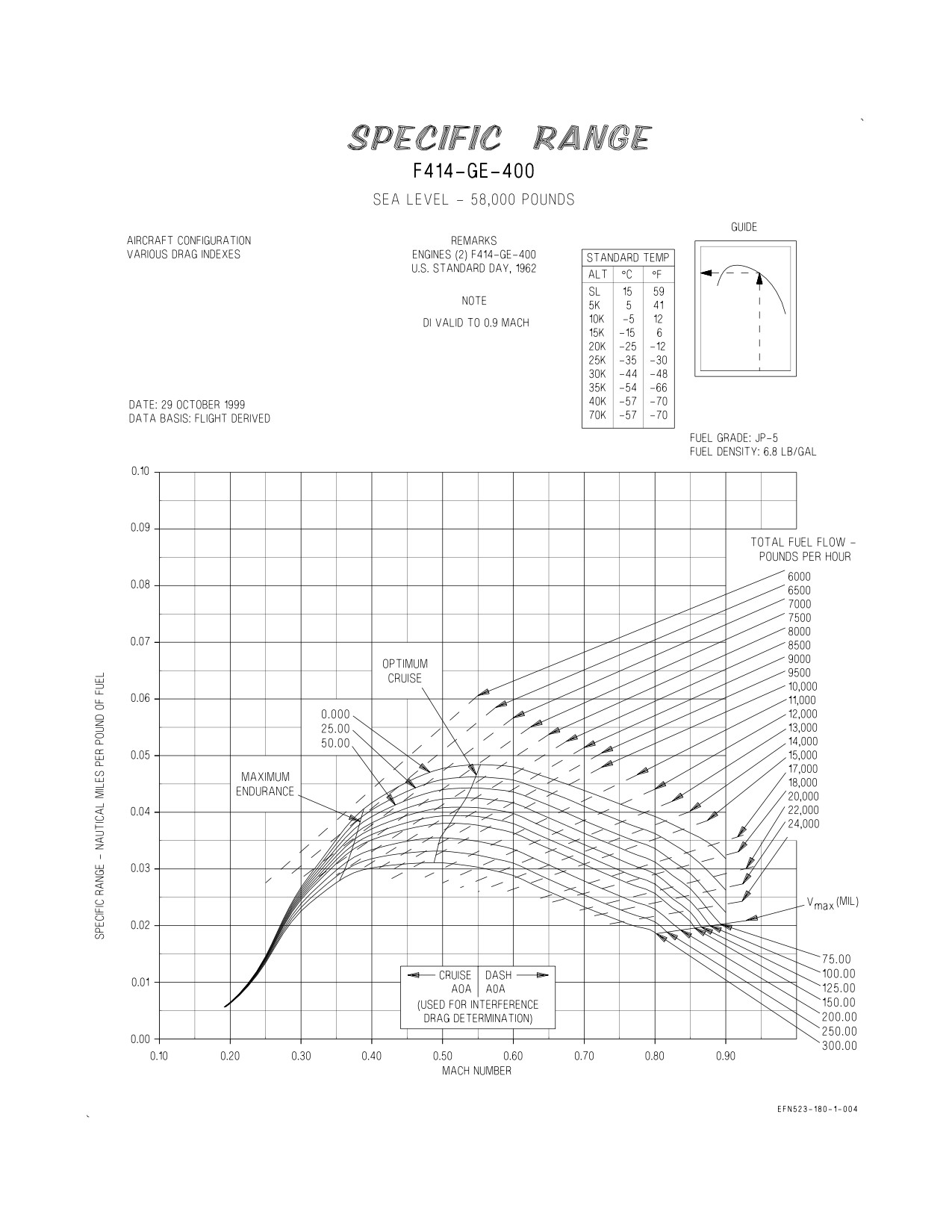
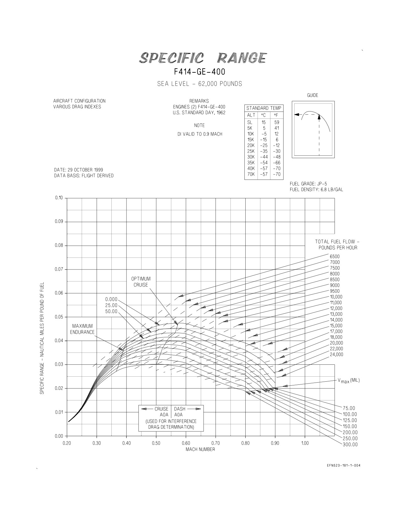
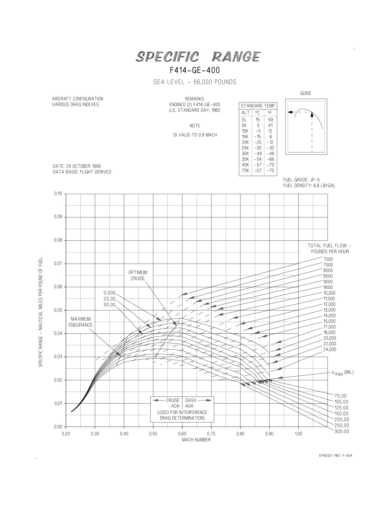
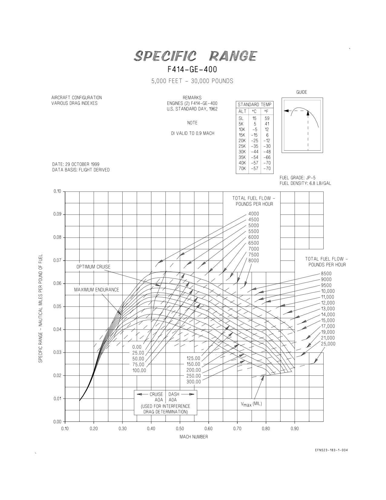
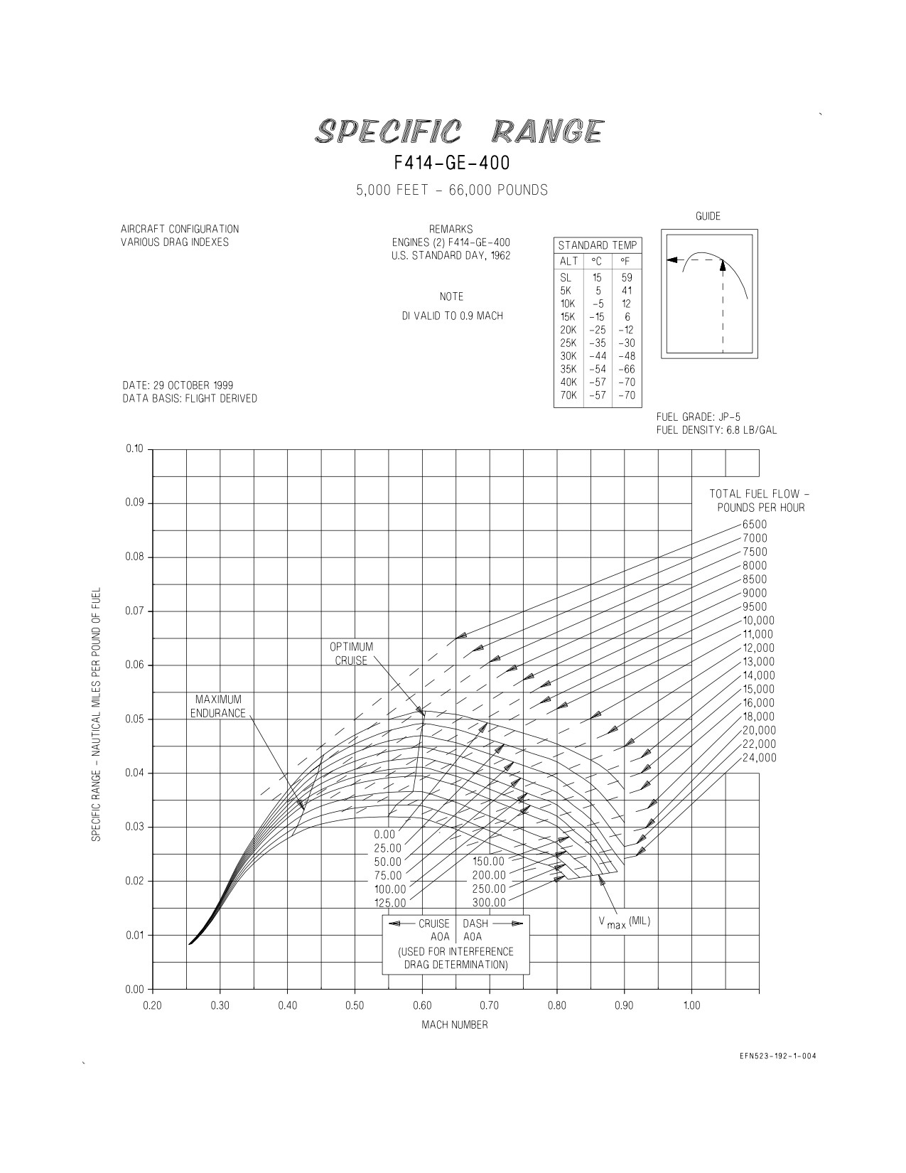
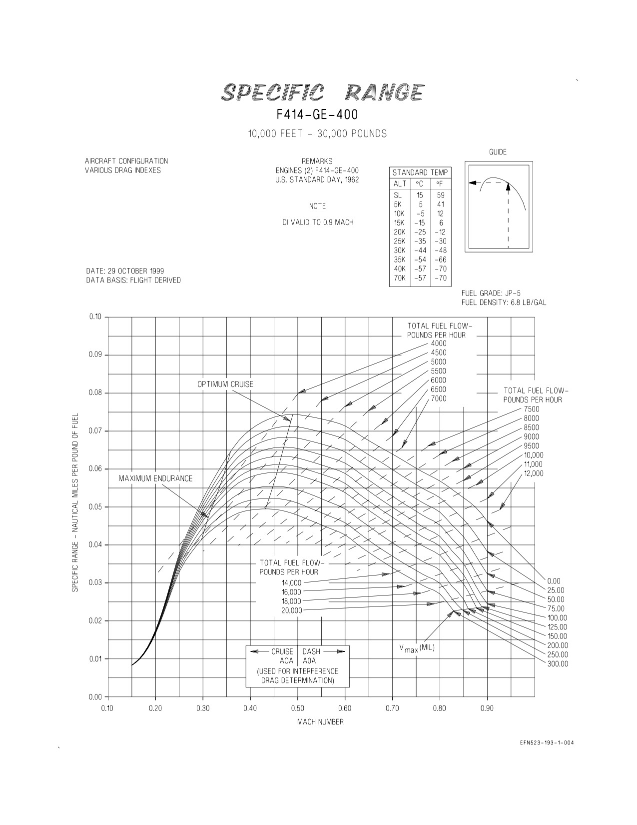
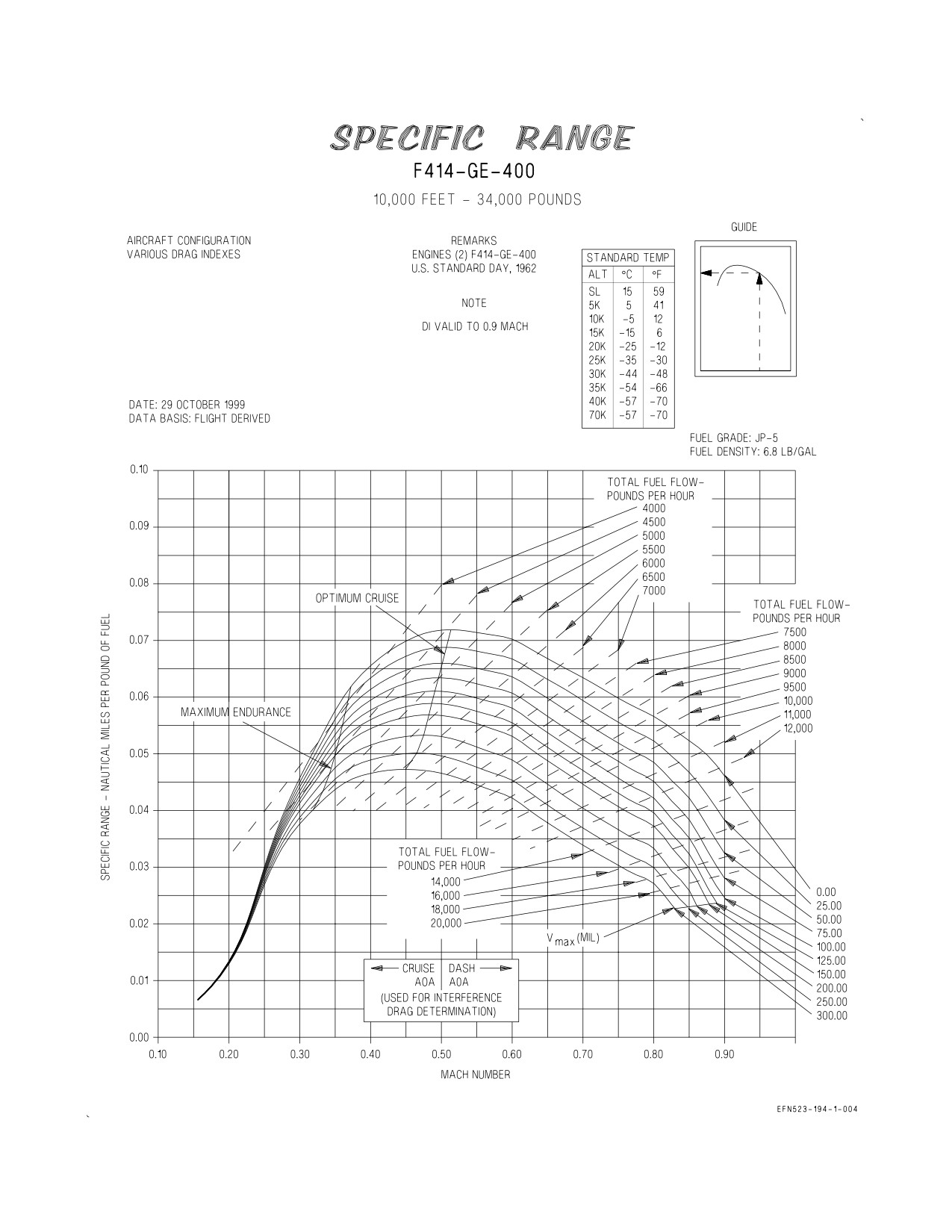
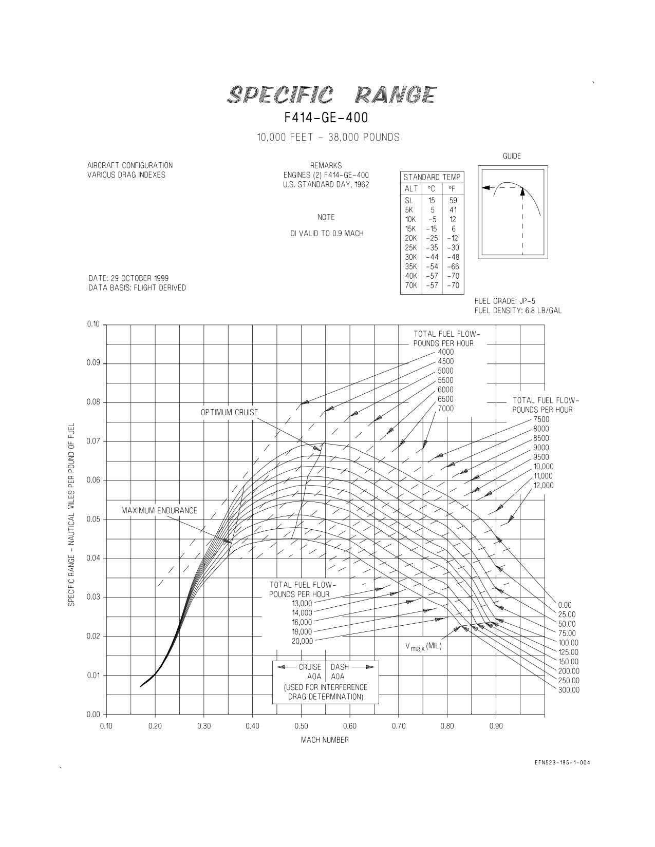
5.2 SPECIFIC RANGE CHARTS
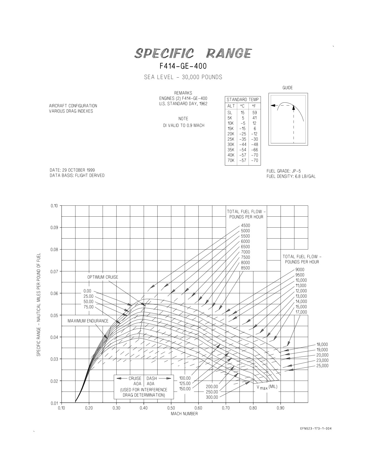
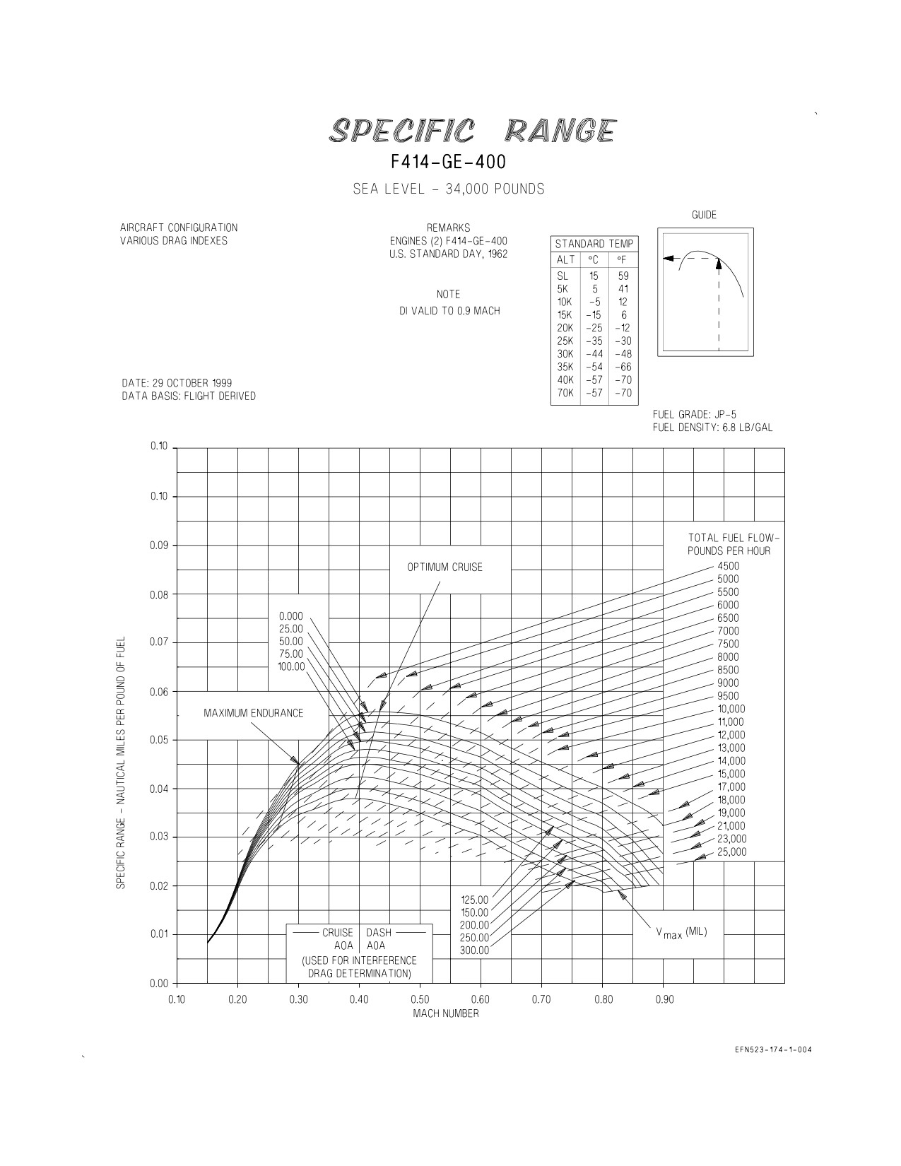
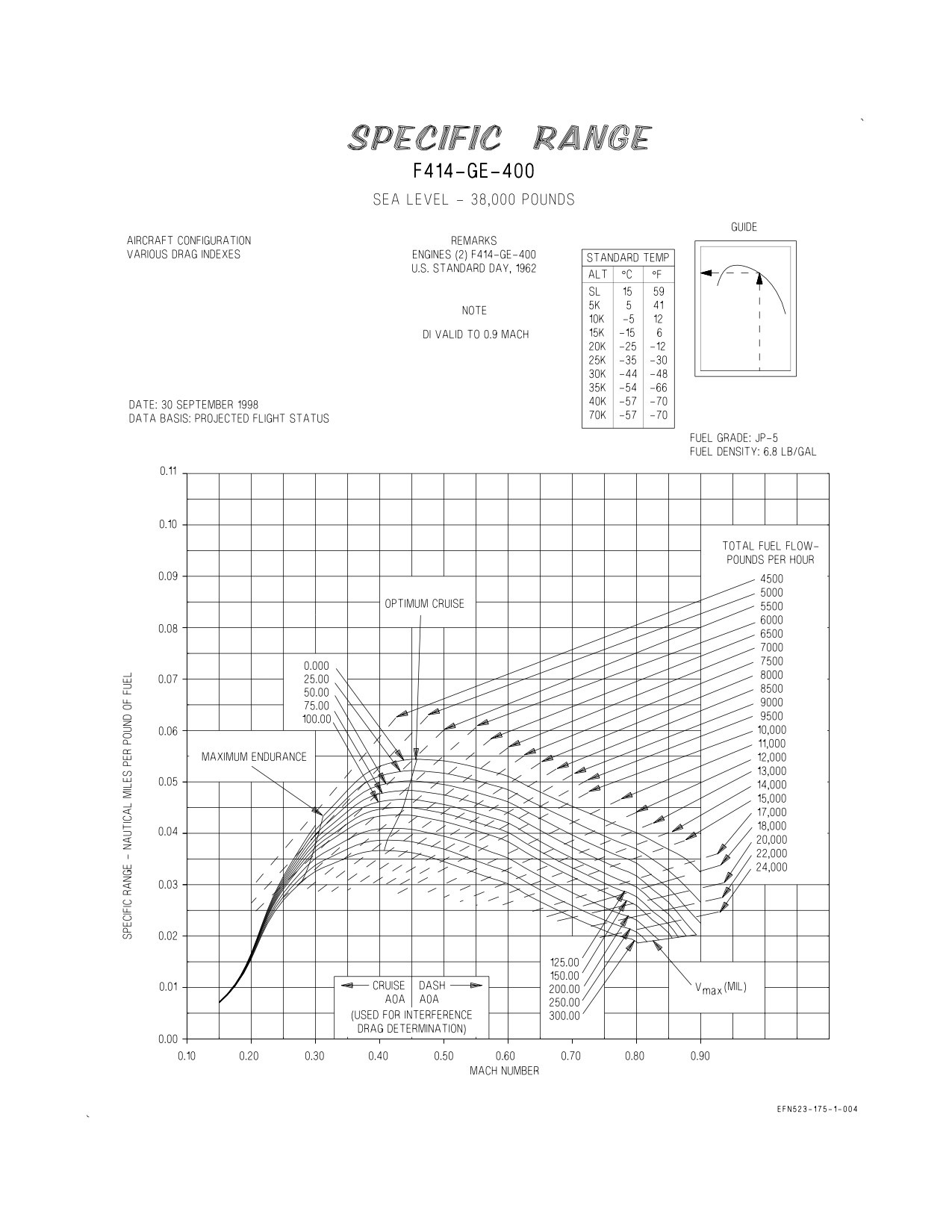
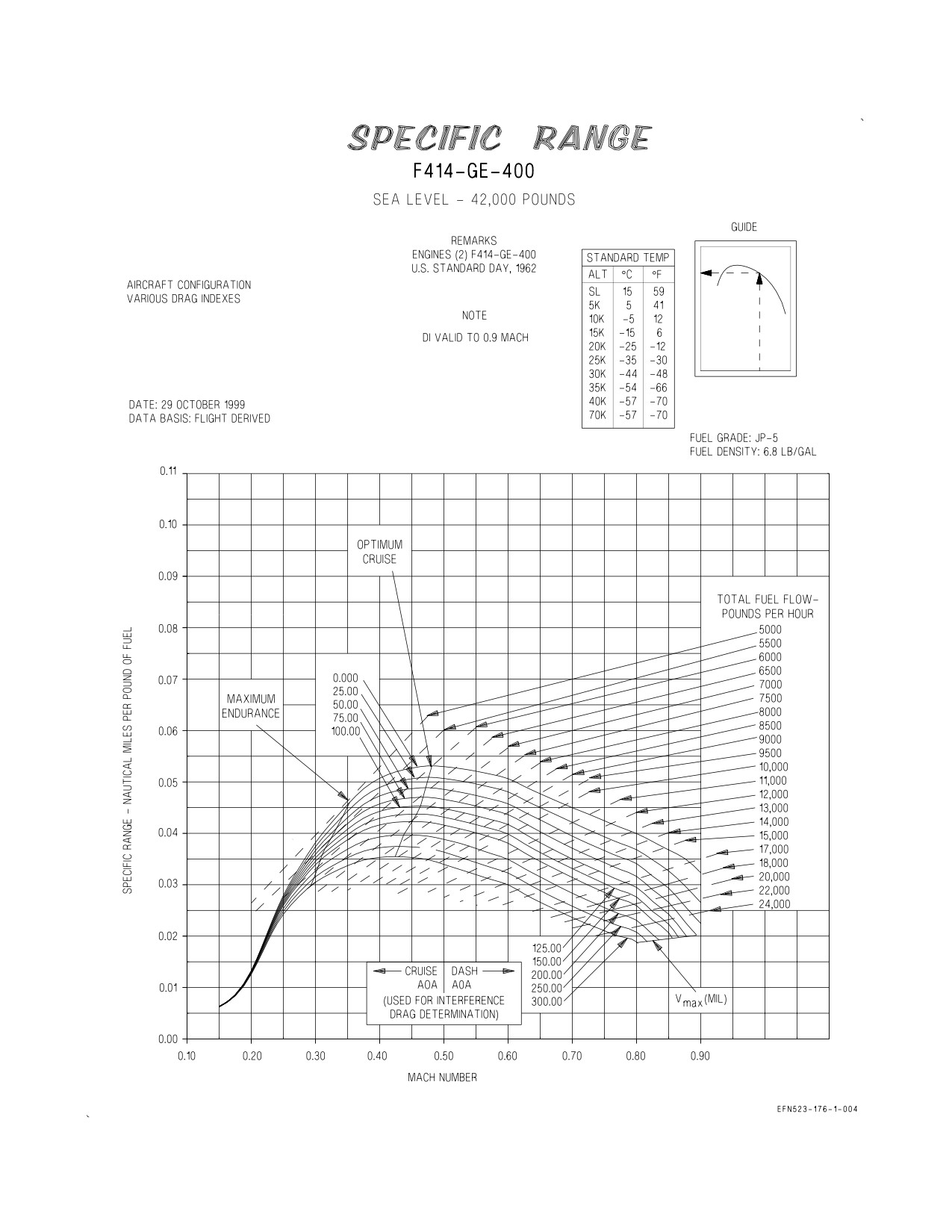
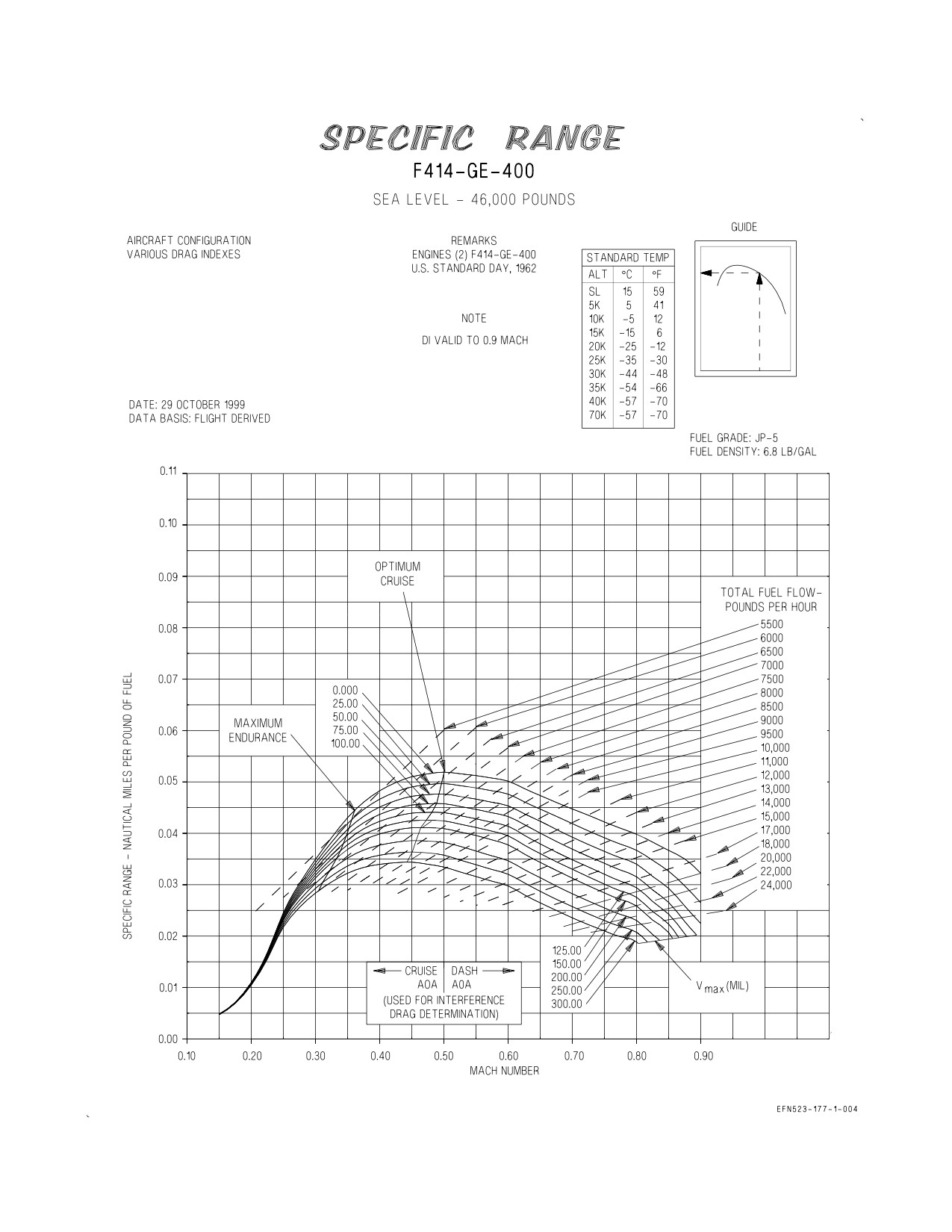
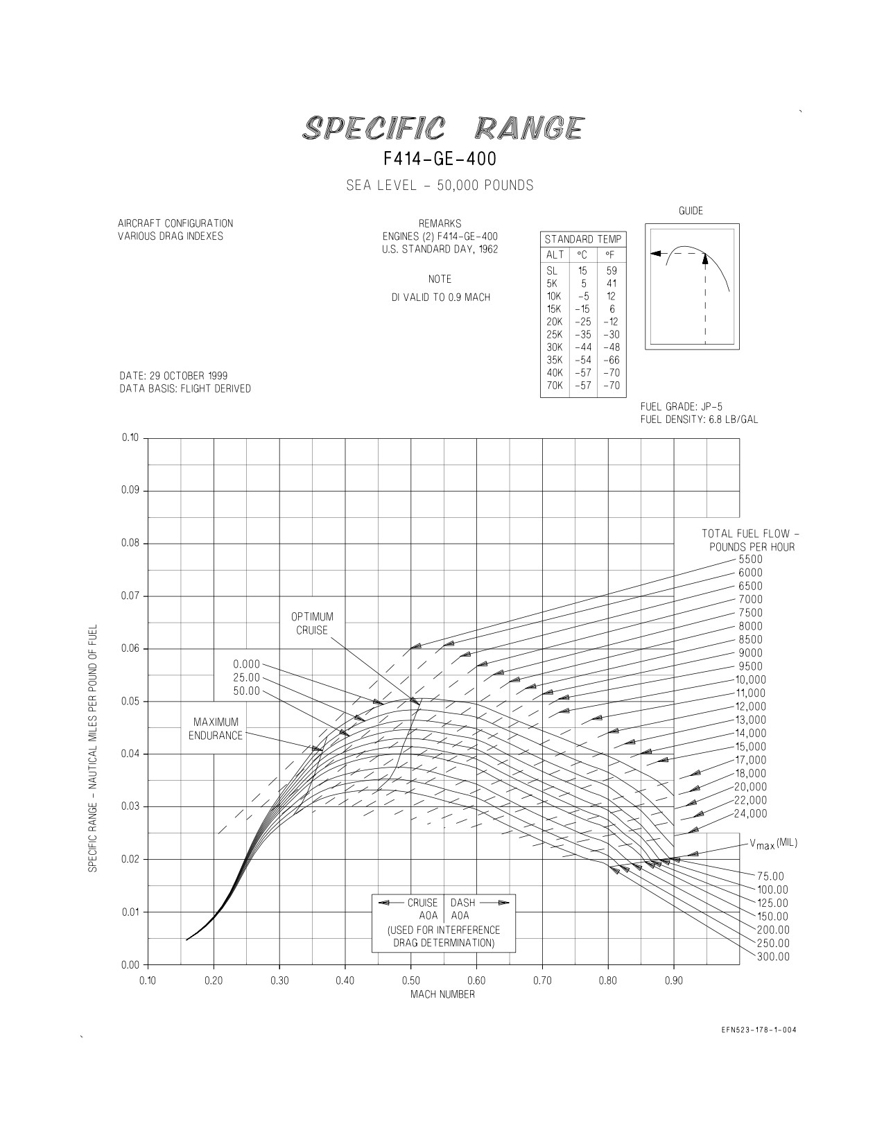
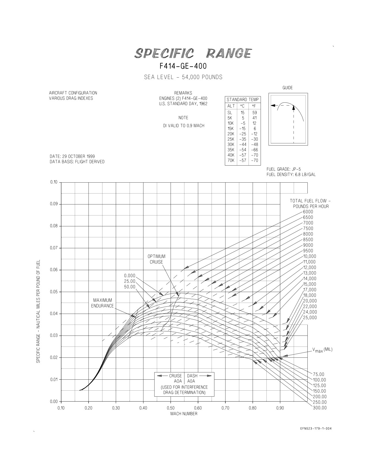
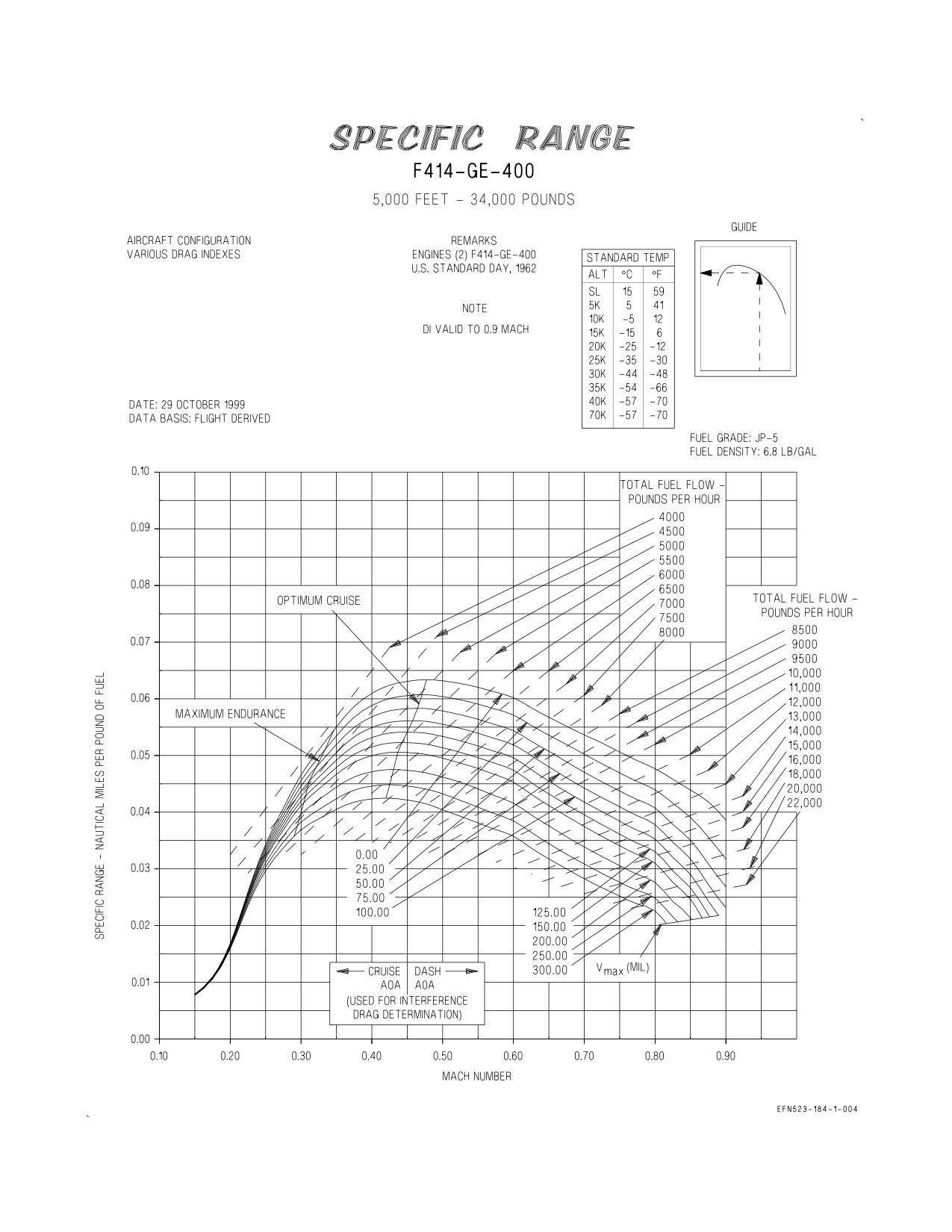
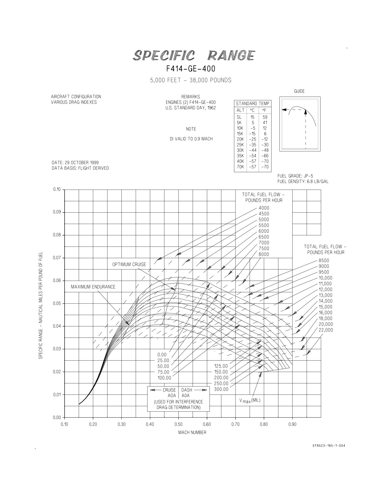
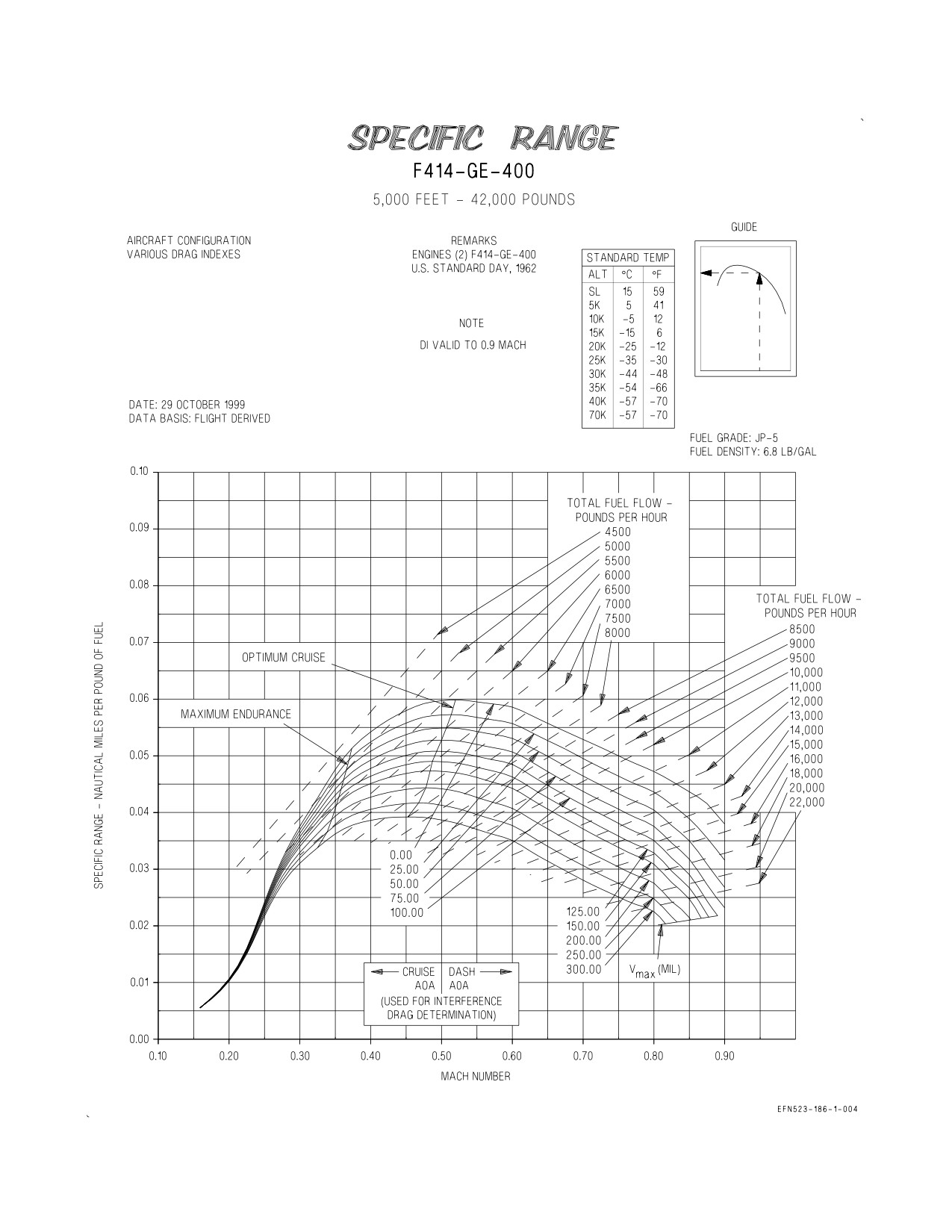
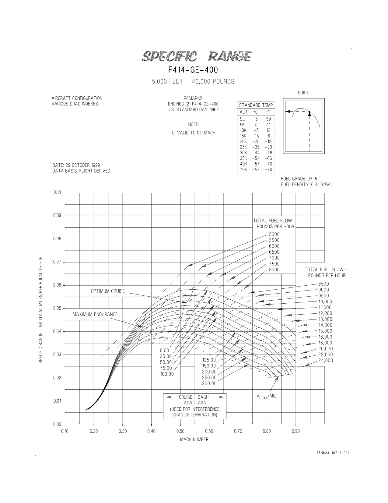
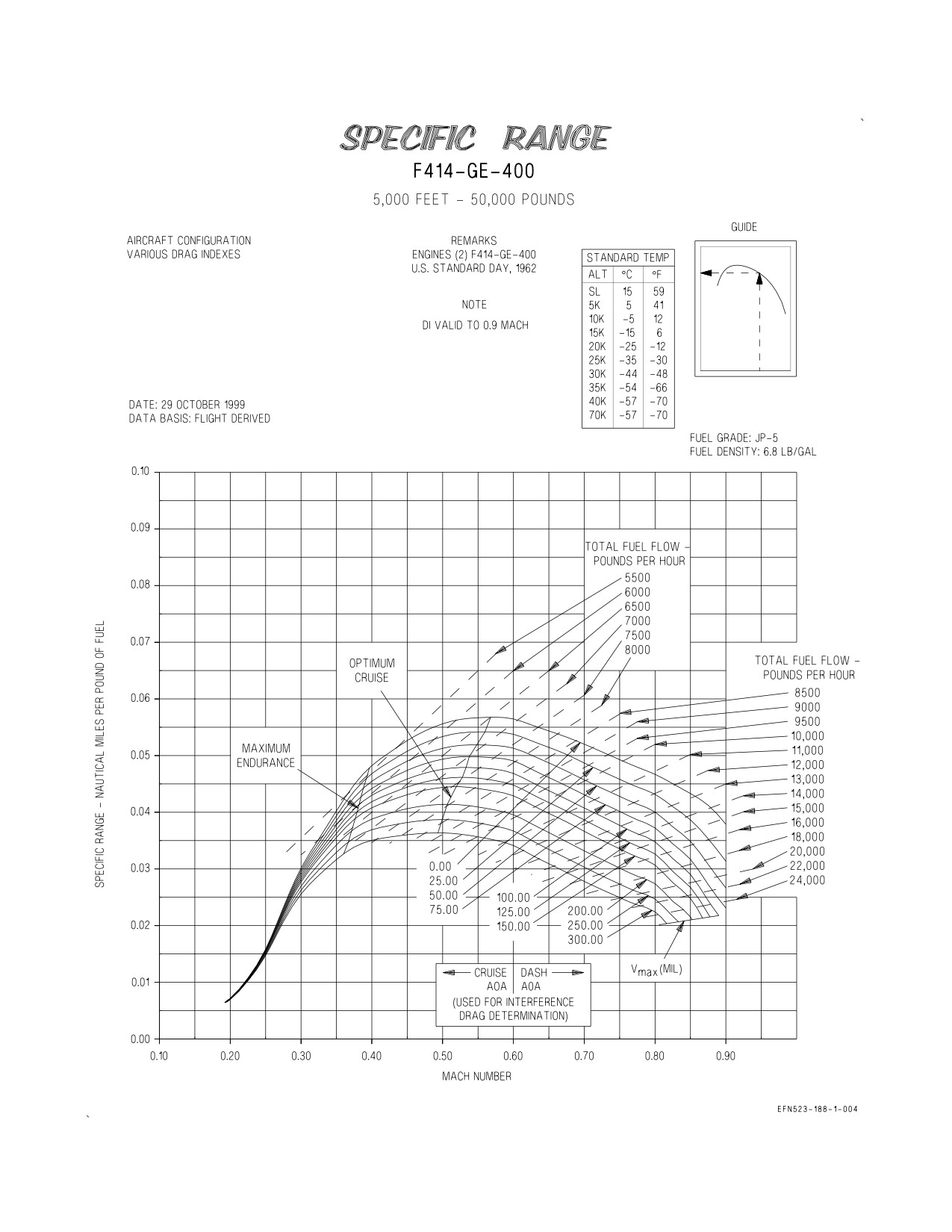
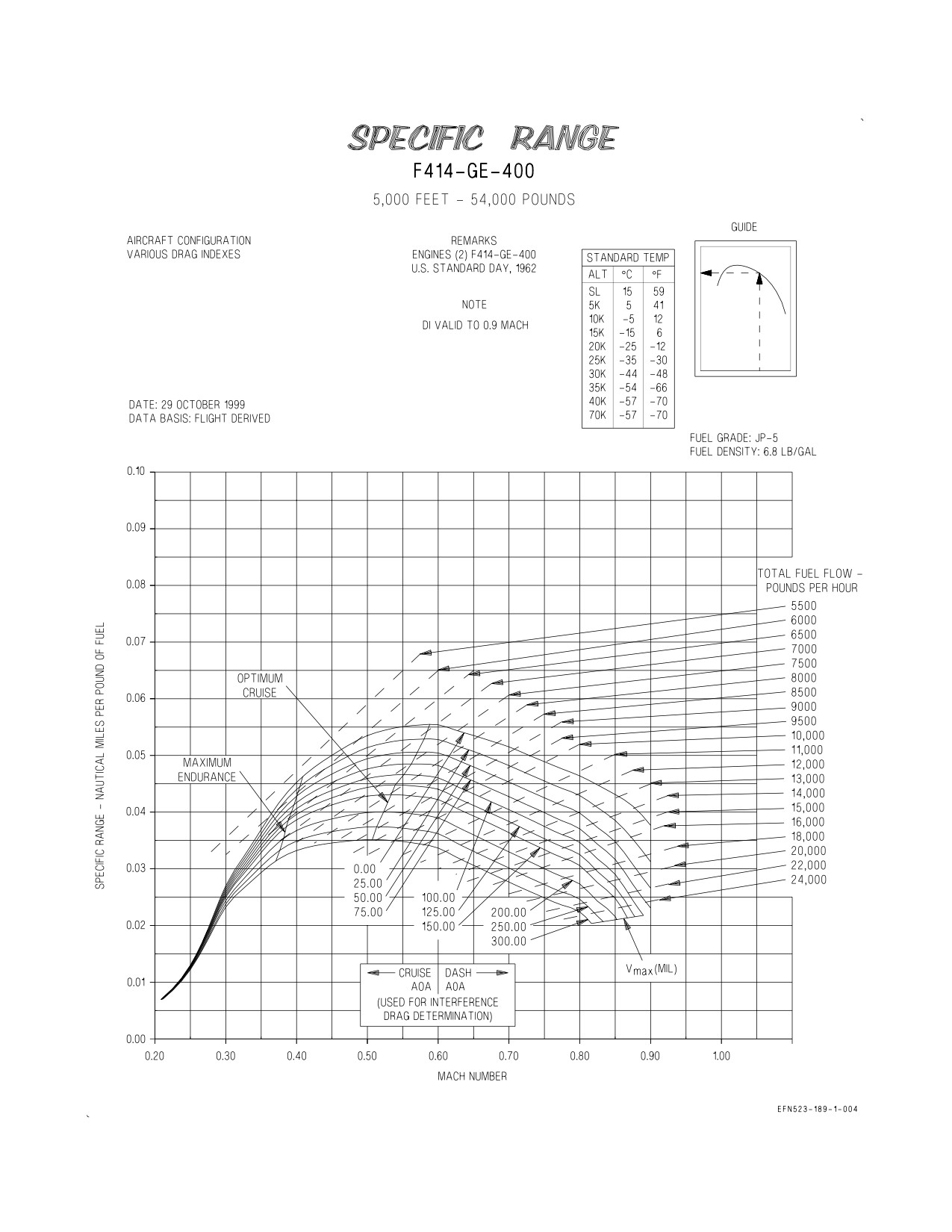
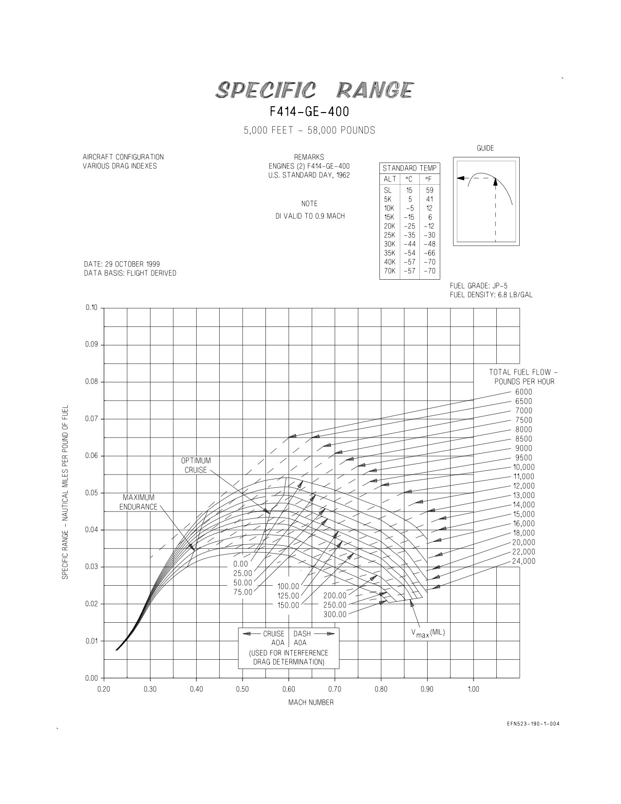
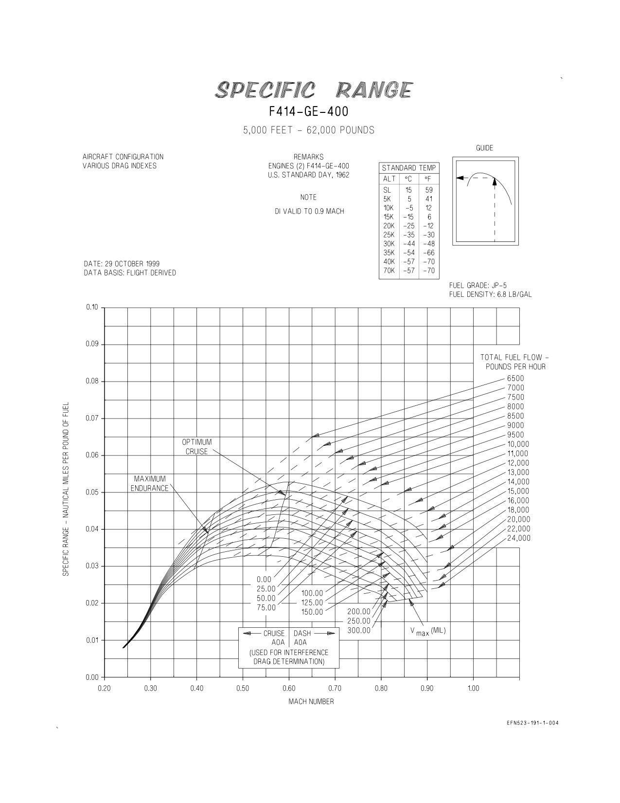
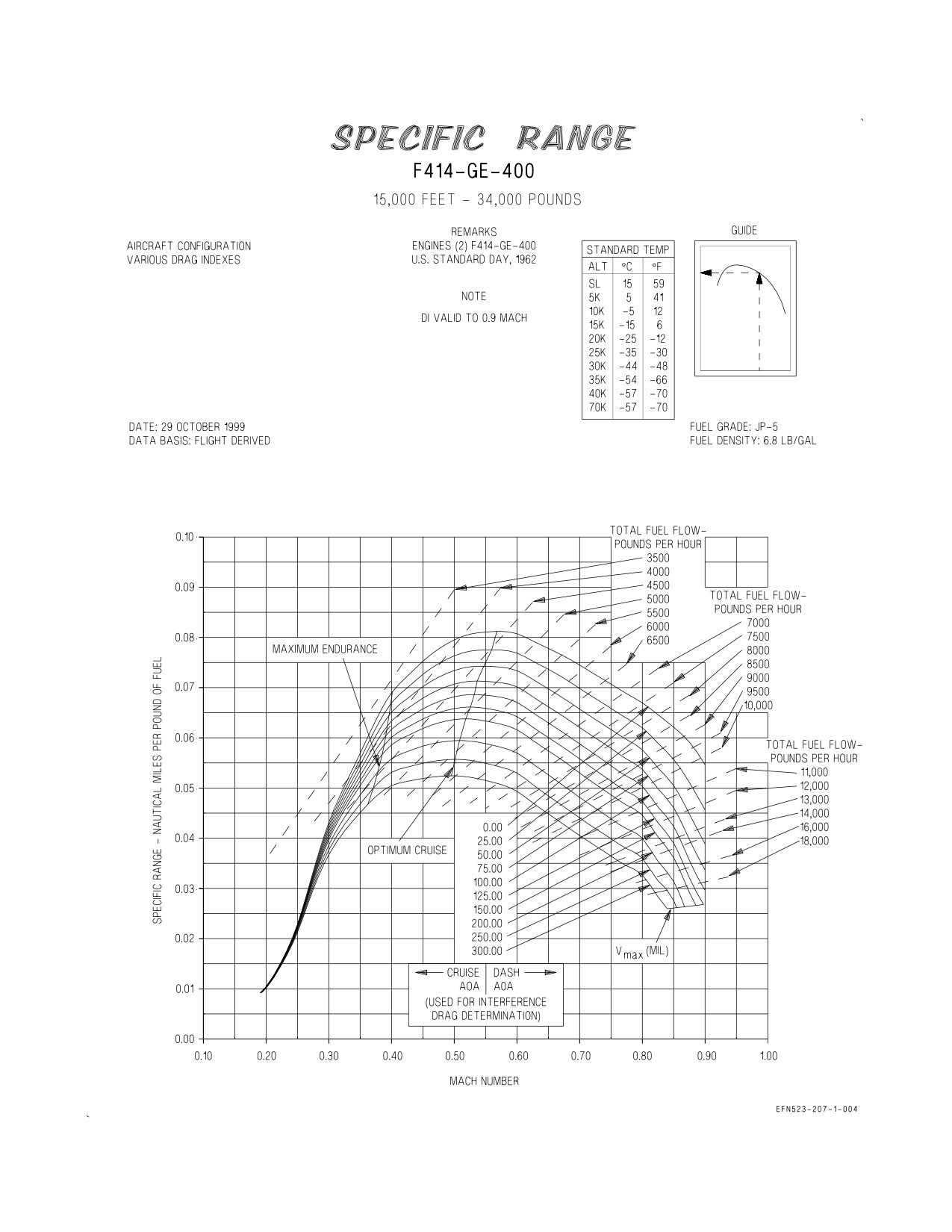
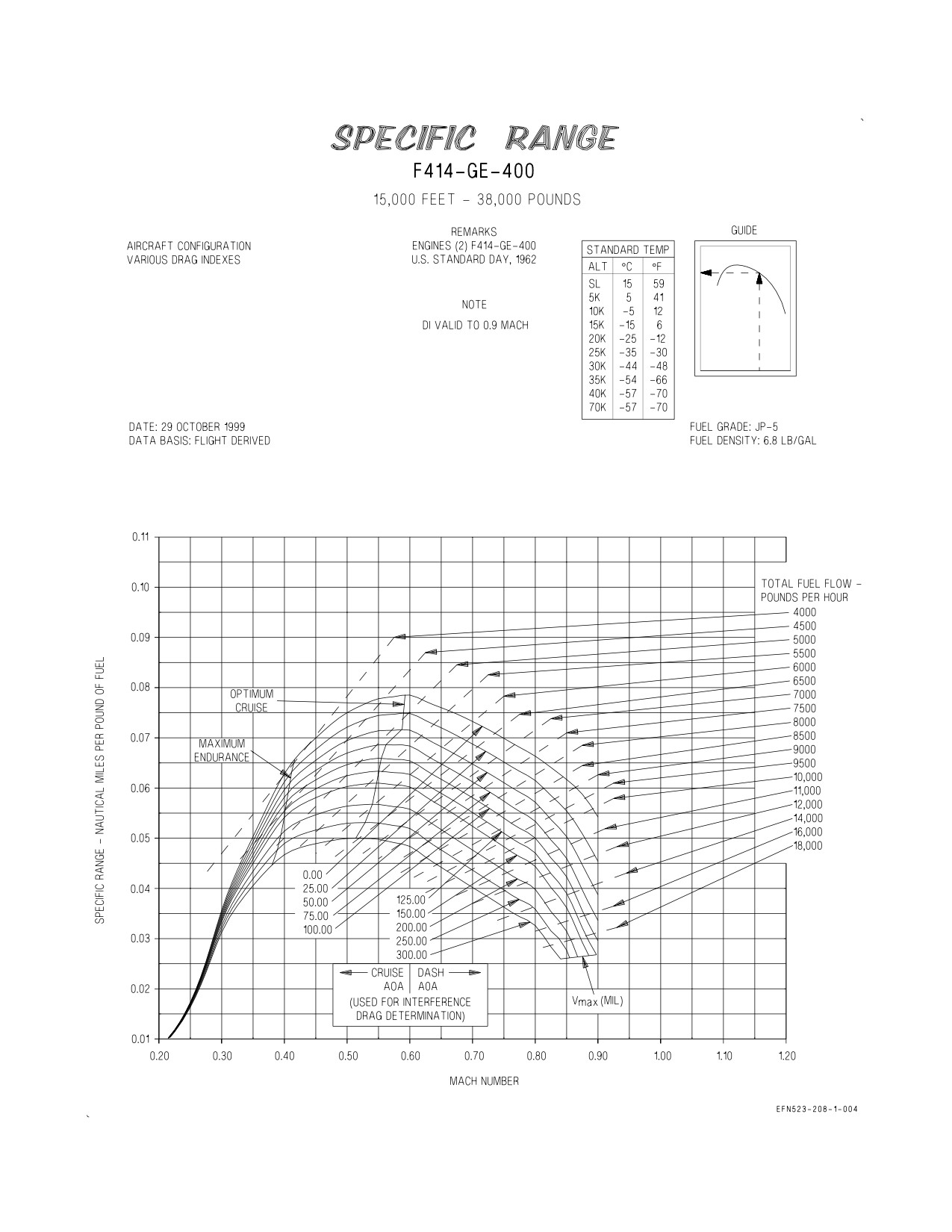
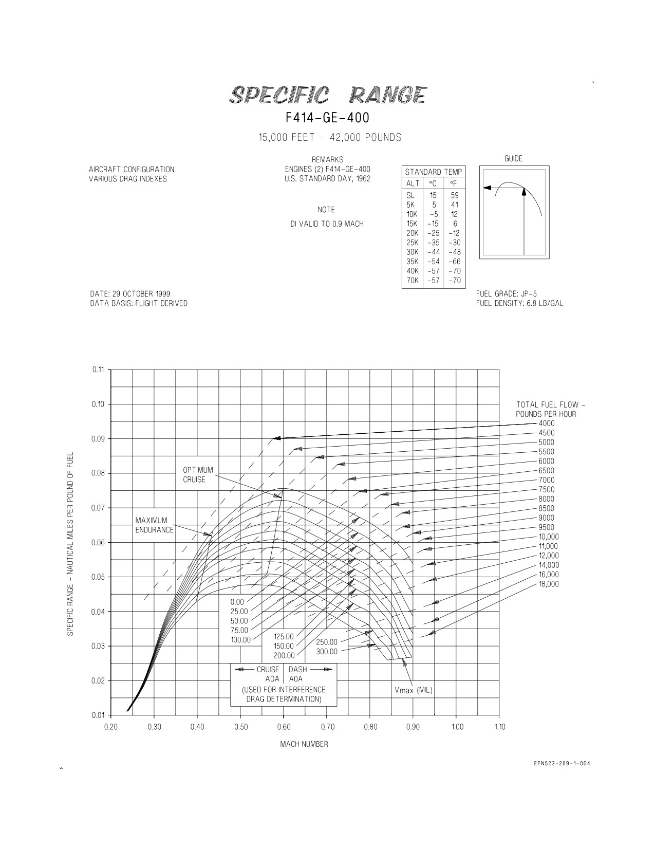
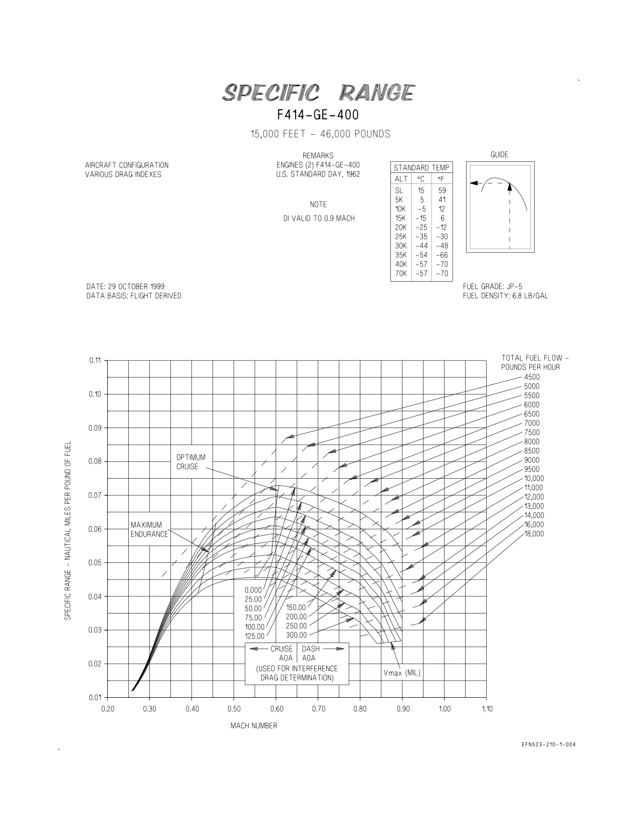
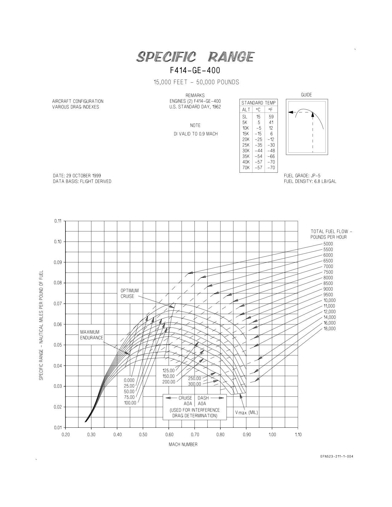
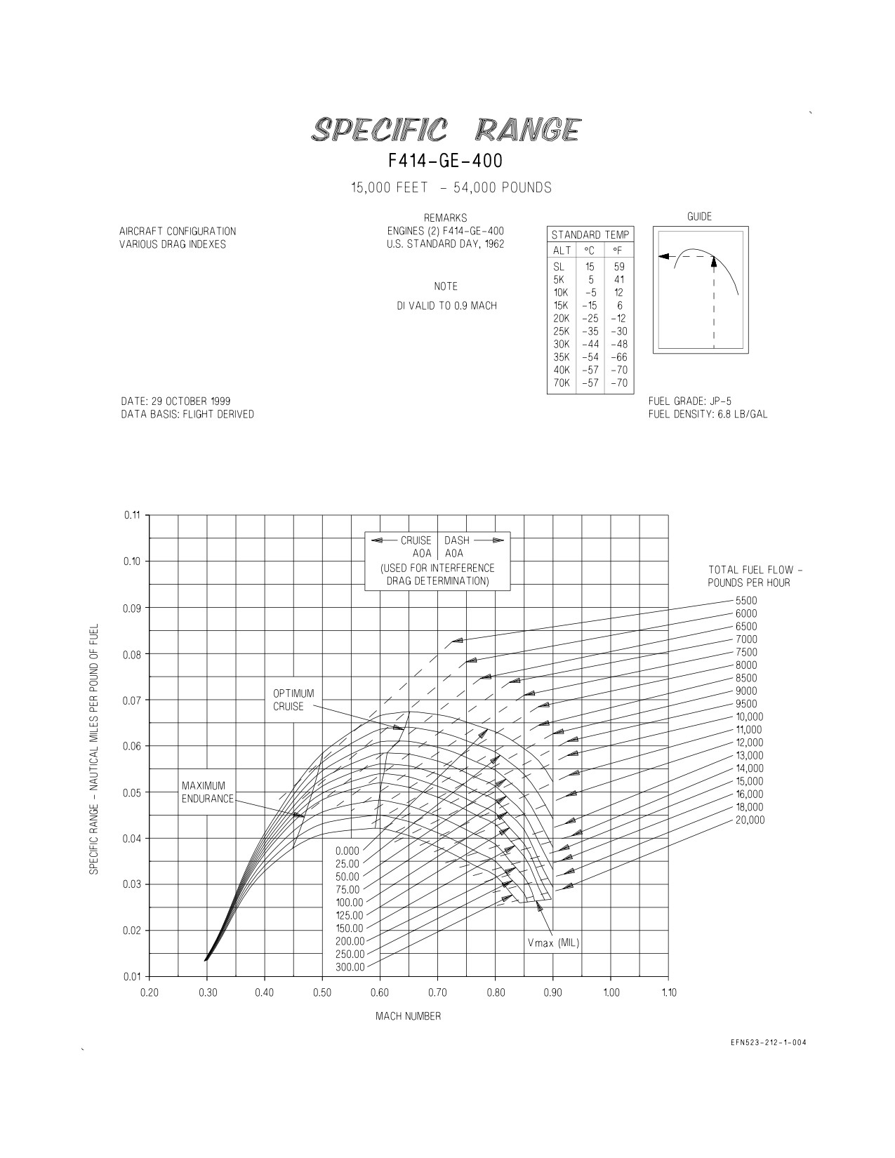
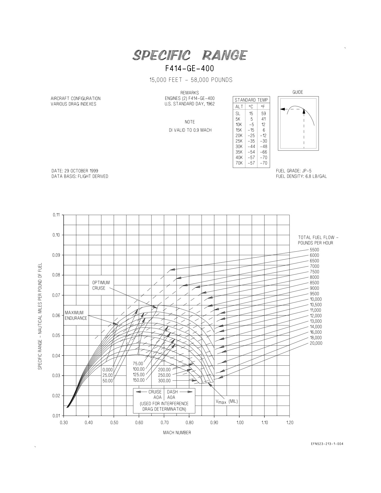
These charts (figures 5-2 thru 5-96 for two engines, figures 5-97 thru 5-160 for 1 engine) present
planning data for constant altitude cruise with various drag indexes at altitudes of sea level, 5,000,
10,000, 15,000, 20,000, 25,000, 30,000, 35,000, 40,000, 45,000, and 50,000 feet and gross weights of 30,000
thru 66,000 pounds in 4,000-pound increments. The charts depict specific range (nautical miles per
pound of fuel (NMPP)) and total fuel flow in pounds per hour for various Mach numbers at cruise AOA
(greater than approximately 2.5°) and dash AOA (approximately 2.5° or lower). Also depicted on the
charts are lines for optimum cruise and maximum endurance.
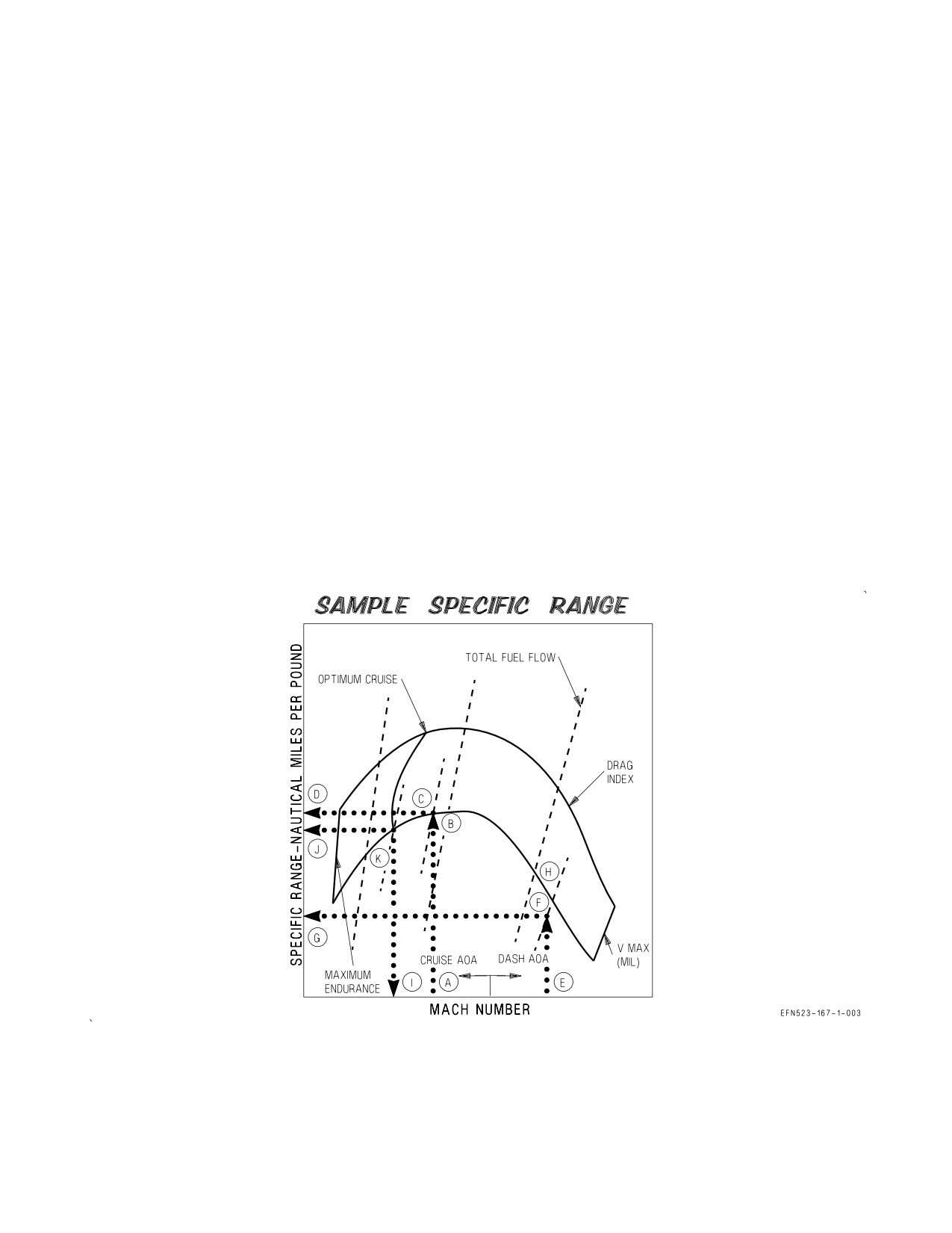
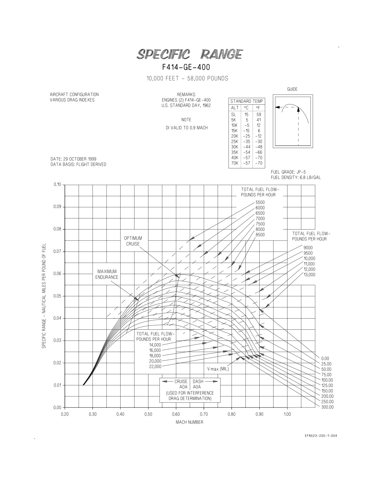
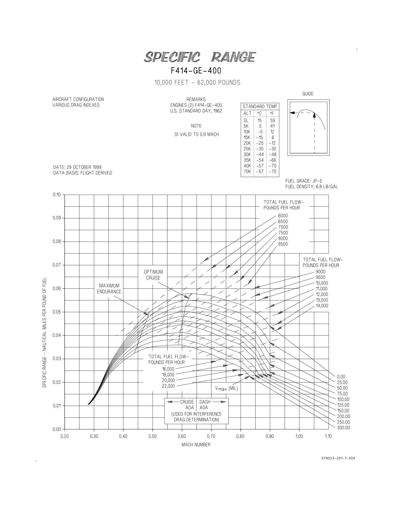
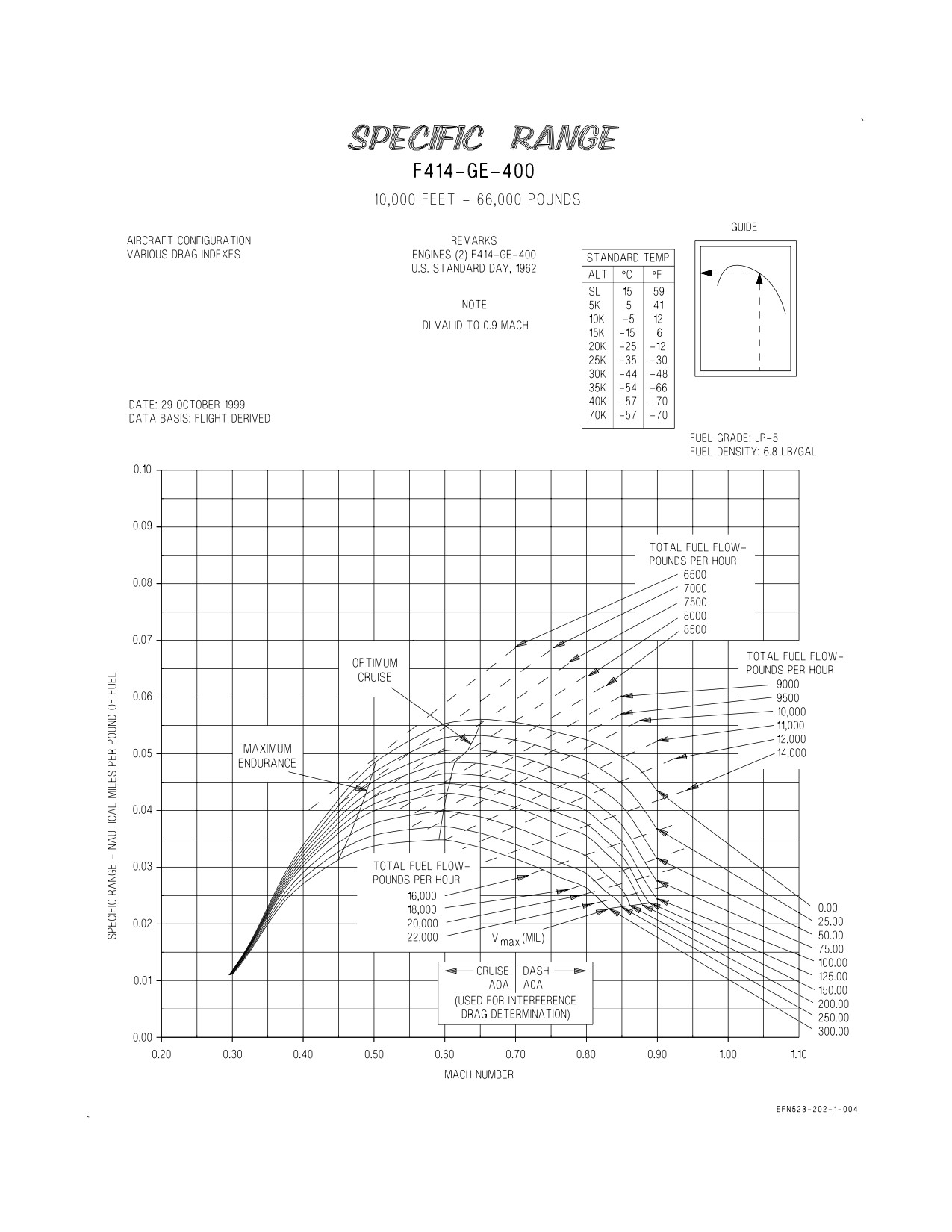
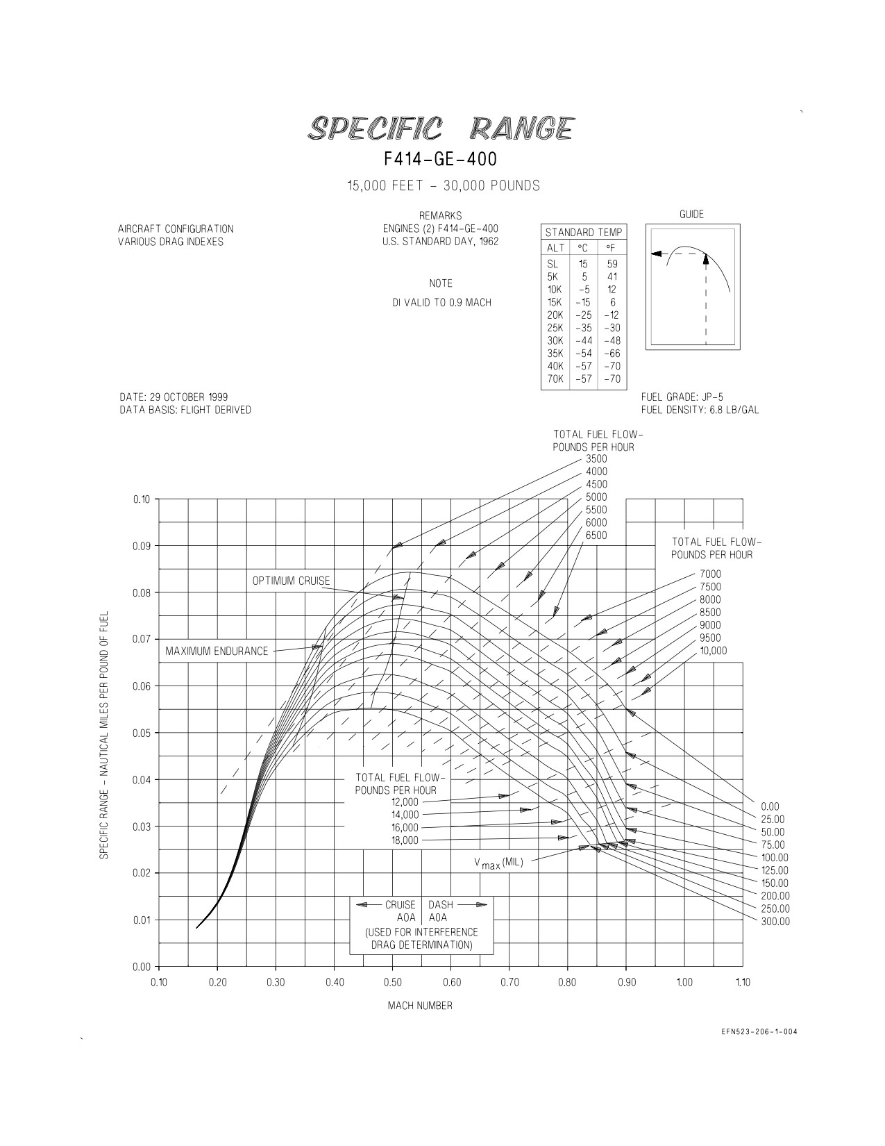
5.2.1 Use. Enter the appropriate chart for desired cruise altitude and gross weight with the desired
Mach number for cruise AOA and project vertically up to the computed drag index. From this point
read total fuel flow, then project horizontally left to read specific range in nautical miles per pound of
fuel. Repeat this process to obtain like data for desired Mach number at dash AOA. Total fuel flow for
any combination of Mach number and drag index can be obtained by interpolating between the total
fuel flow lines provided on the charts. Mach number, total fuel flow and specific range for optimum
cruise can be obtained by entering the chart on the optimum cruise line at the appropriate drag index
XI-5-2
CHANGE 1
A1-F18EA-NFM-200
and projecting vertically down and horizontally left to read Mach number and specific range
respectively. Maximum endurance data is obtained in an identical manner entering the chart on the
line labeled maximum endurance. Maximum Mach number at a particular drag index and military
power setting can be obtained by reading the VMAX curve at that drag index.
5.2.2 Sample Problem. Chart: 5000 Feet - 42,000 Pounds (figure 5-15) Problem based on loading in
figure 2-1.
A. Mach number
0.6
(cruise AOA)
B. Drag index (total)
163.3
C. Total fuel flow
9000 PPH
D. Specific range
0.044 NMPP
E. Mach number
0.8
(dash AOA)
F. Drag index (total)
179.3
G. Specific range
0.029 NMPP
H. Total fuel flow
18,000 PPH
I. Mach number
0.485
(optimum cruise)
J. Specific range
0.046 NMPP
K. Total fuel flow
6800 PPH
XI-5-3
ORIGINAL
A1-F18EA-NFM-200
5.3 COMBAT SPECIFIC RANGE CHARTS
These charts (figure 5-161) present the specific range and the general thrust settings required to
maintain a constant Mach number for a U.S. standard day and standard day +10°C at all altitudes
from sea level to 45,000 feet. The specific range values are based on a stabilized level flight condition
and do not represent the fuel flow required to accelerate to a given Mach number.
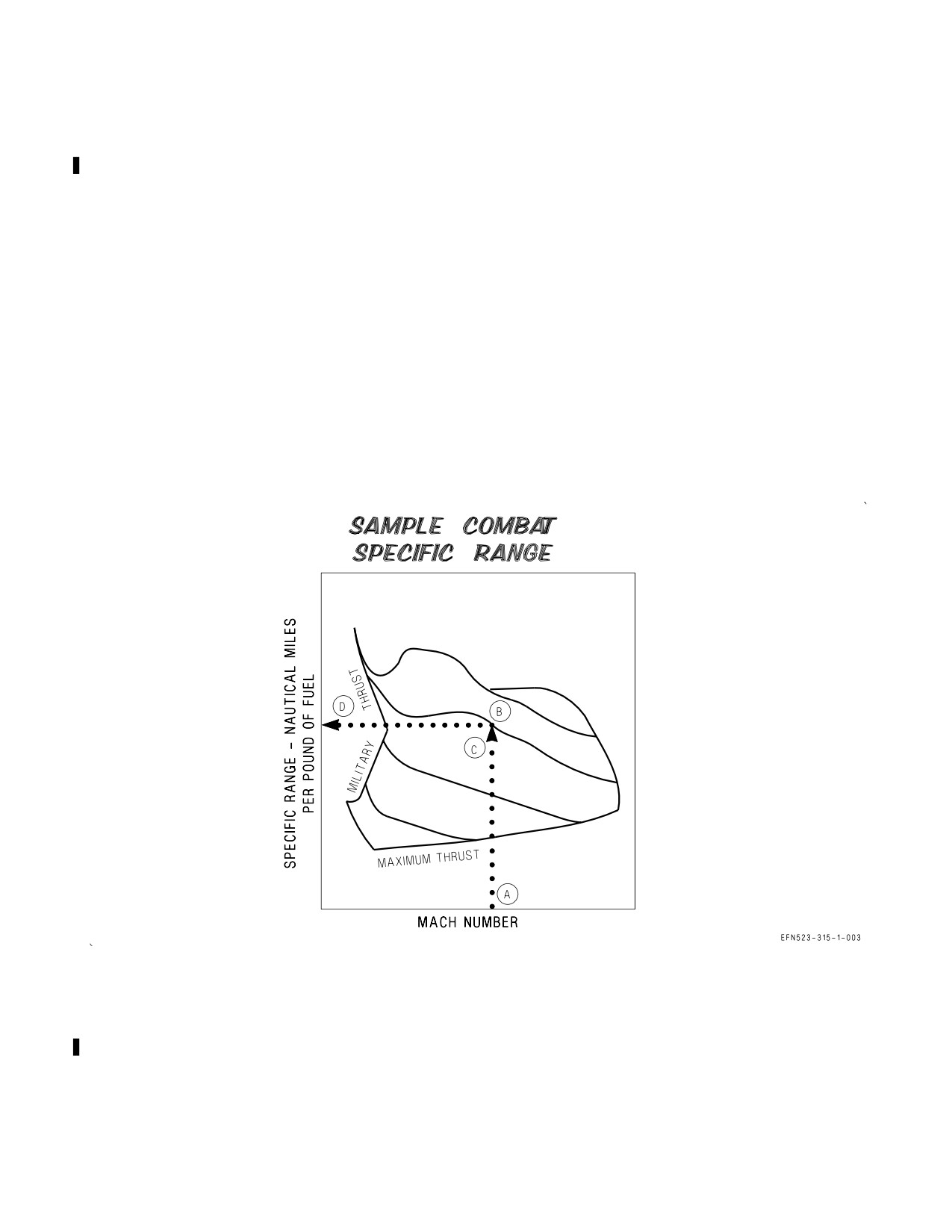
5.3.1 Use. Enter the chart corresponding to the aircraft configuration with the desired Mach number
for stabilized level flight. Proceed vertically upward to the selected flight altitude. Note the general
thrust setting required, and then project horizontally left to obtain the specific range.
5.3.2 Sample Problem. Configuration - (2)AIM-9 +(2)AIM-120.
A. Desired Mach number
1.2
B. Altitude (Standard Day)
30,000 Ft.
C. Thrust setting required
Mod. Afterburners
D. Specific range
0.022 NMPP
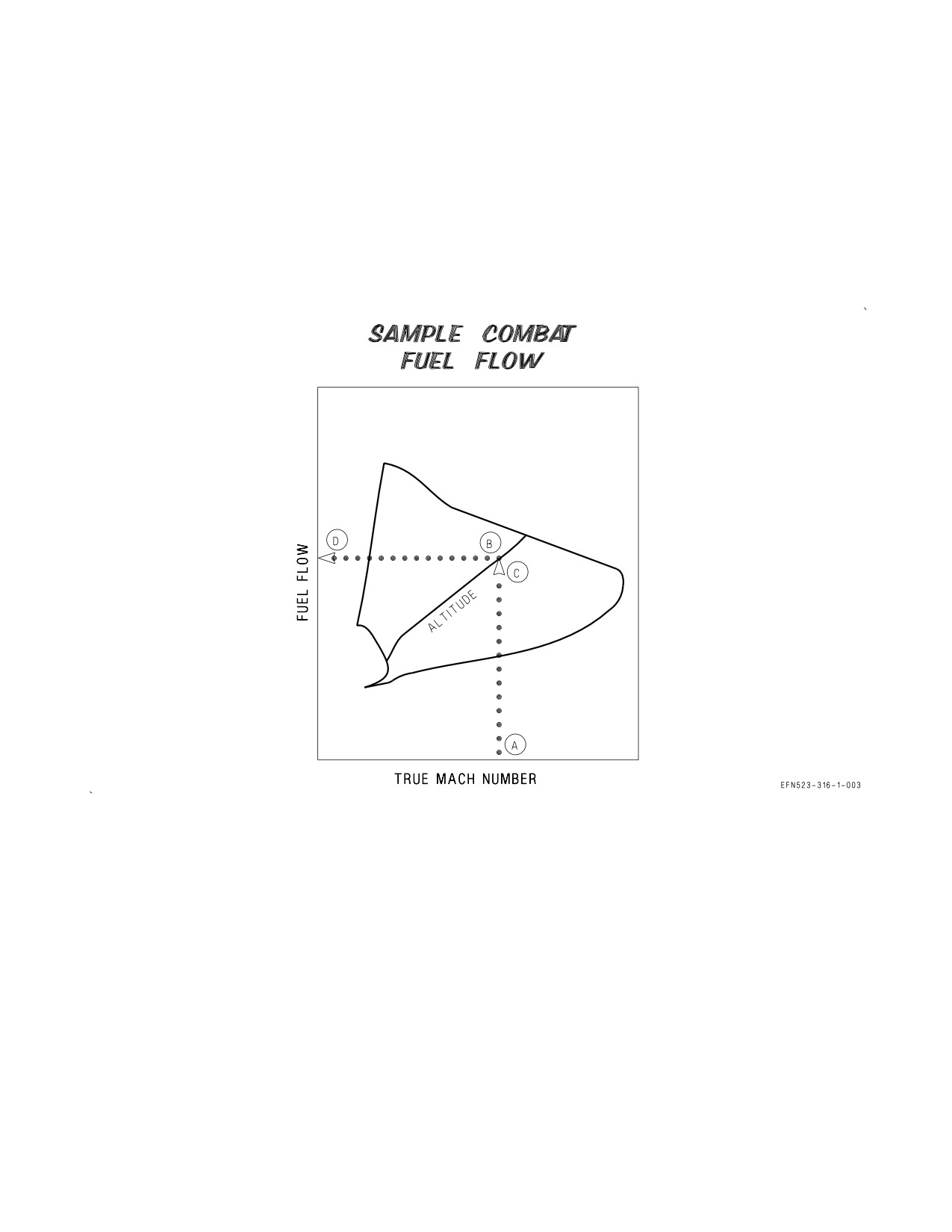
5.4 COMBAT FUEL FLOW CHARTS
These charts (figure 5-162) present the specific fuel flow and general thrust setting to maintain a
constant Mach number for a U.S. standard day and standard day +10°C at all altitudes between sea
level and 45,000 feet. Each chart is plotted for a specific configuration. The fuel flow values are based
on a stabilized level flight condition and do not represent the fuel flow required to accelerate to a given
Mach number.
XI-5-4
CHANGE 1
A1-F18EA-NFM-200
5.4.1 Use. Enter the chart corresponding to the aircraft configuration with the desired Mach number
for stabilized level flight. Proceed vertically upward to the selected flight altitude. Note the general
thrust setting required, and then project horizontally to the left to read specific fuel flow.
5.4.2 Sample Problem. Configuration - (2) AIM-9 + (2)AIM-120.
A. Desired Mach number
1.2
B. Altitude (Standard Day)
20,000 Ft.
C. Thrust setting required
Mod. Afterburners
D. Specific fuel flow
970 Lb/Min.
XI-5-5
ORIGINAL
A1-F18EA-NFM-200
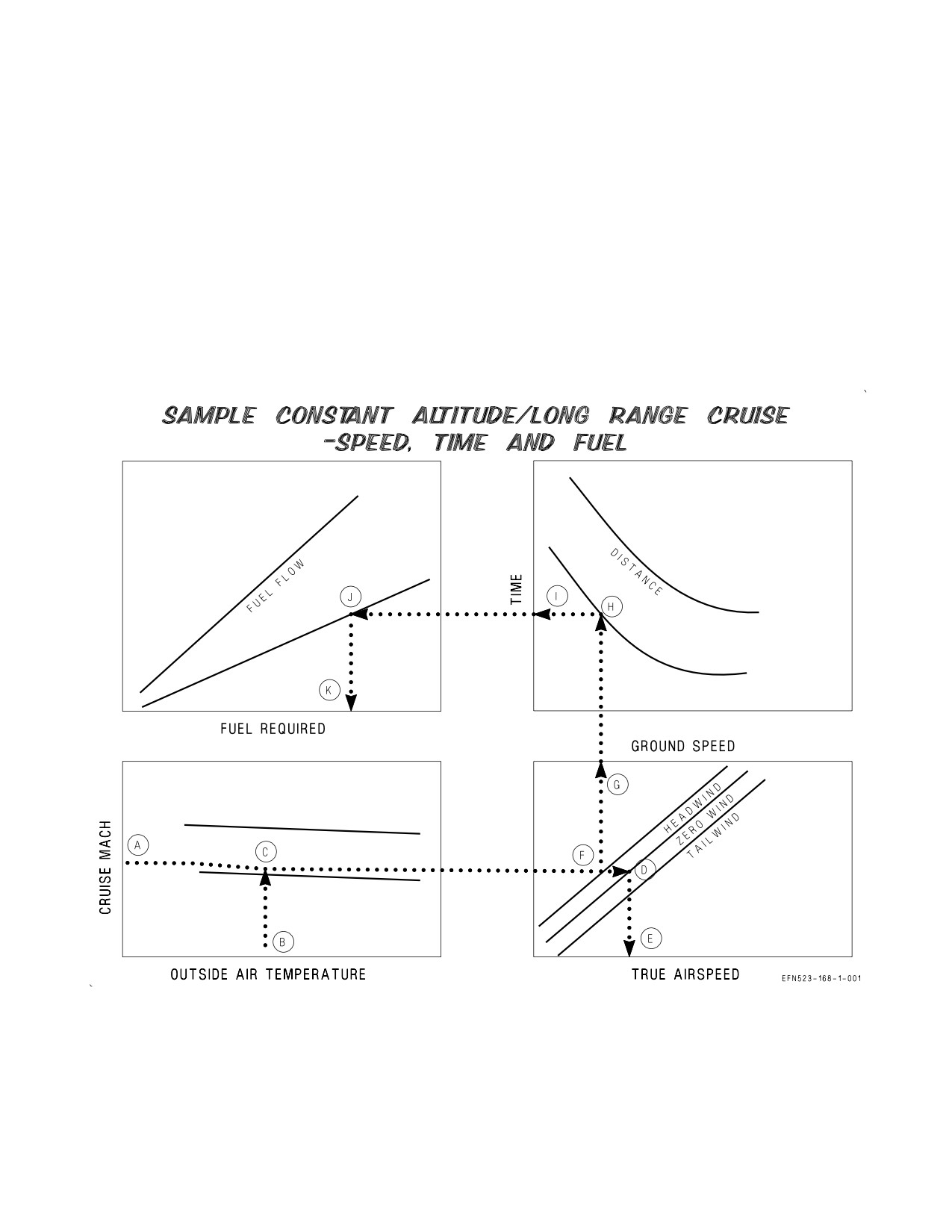
5.5 CONSTANT ALTITUDE/LONG RANGE CRUISE (SPEED-TIME-FUEL) CHART
This chart (figure 5-163, sheet 1) is used to determine the airspeed, time, and fuel required to travel
a given distance when the cruise Mach number, outside air temperature (OAT), wind component at
altitude, and fuel flow are known. The chart may be used for single engine or two-engine operation.
5.5.1 Use. Enter the chart with the desired cruise Mach number and parallel the guidelines to
intersect a vertical line projected up from the outside air temperature scale. From this point, project
horizontally to the zero wind component line, then vertically down to read true airspeed. If winds are
expected at the cruise altitude, trace back to the zero wind line and project horizontally to the
appropriate headwind or tailwind line, then vertically up to read groundspeed. From this point,
continue to project vertically up to the selected distance curve, then horizontally left to read time
required. Continue to project horizontally left to the appropriate fuel flow line, then vertically down to
read fuel required.
XI-5-6
CHANGE 1
A1-F18EA-NFM-200
5.5.2 Sample Problem.
A. Cruise Mach
0.65
B. OAT
20°F
C. Intersect OAT
D. Wind component
0
E. True airspeed
410 Kt.
F. Headwind
50 Kt.
G. Groundspeed
360 Kt.
H. Selected distance
600 NM
I. Time required
100 Min.
J. Fuel flow
4000 PPH
K. Fuel required
6667 Lb.
XI-5-7
ORIGINAL
A1-F18EA-NFM-200
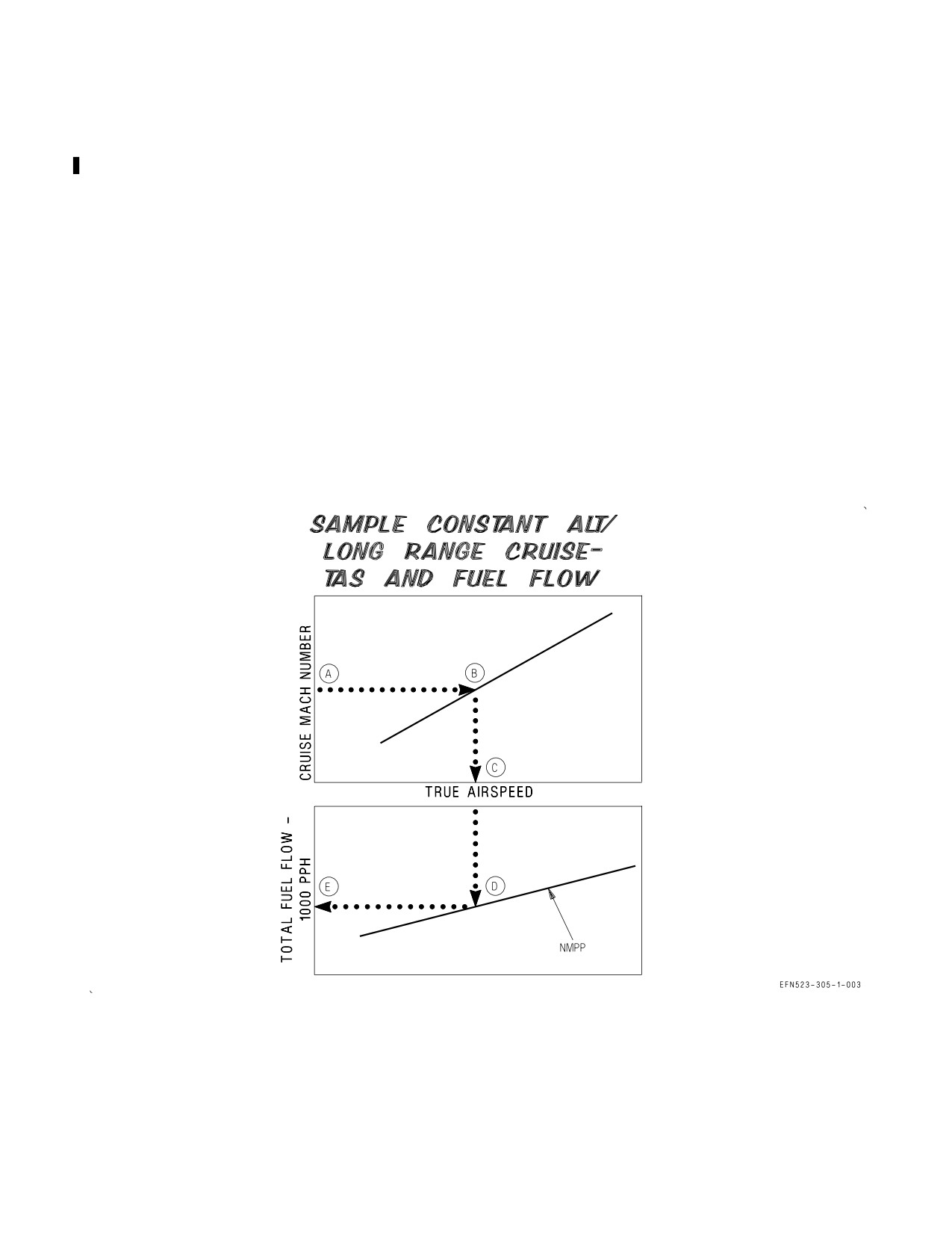
5.6 CONSTANT ALTITUDE/LONG RANGE CRUISE (TRUE AIRSPEED AND FUEL FLOW) CHART
This chart (figure 5-163, sheet 2) is used to determine the true airspeed and total fuel flow when the
cruise Mach number, outside air temperature (OAT), and specific range are known at a particular
cruise condition. The chart may be used for single engine or two-engine operation.
5.6.1 Use. Enter the chart with the desired cruise Mach number and project horizontally right to the
outside air temperature curve. Project horizontally down to read true airspeed and continue projection
down to the specific range (nautical miles per pound) curve as determined from the specific range
charts at the gross weight, altitude and drag index of interest. From the intersection of the nautical
miles per pound curve project horizontally left to read total fuel flow.
5.6.2 Sample Problem.
A. Cruise Mach
0.52
B. OAT
-20°C
C. True Airspeed
320 Kt.
D. Specific Range
0.0400 NMPP
E. Total Fuel Flow
8100 PPH
XI-5-8
CHANGE 1
A1-F18EA-NFM-200
5.7 BINGO CHARTS
These charts (figures 5-164 thru 5-171) show altitude, fuel, and airspeed required to travel a given
distance based on various headwinds. Charts are provided for two-engine and single engine operation
at various combinations of drag index, weight, and gear up and gear down configurations. Fuel required
values include a 1,800 pound reserve. Data are provided for cruise at both optimum cruise altitude and
at sea level.
5.8 MAXIMUM RANGE AOA/MAXIMUM ENDURANCE AOA CHART
The Maximum Range AOA/Maximum Endurance AOA chart (figure 5-172) shows the AOA required
to achieve maximum range or maximum endurance based on the aircraft drag index configuration.
XI-5-9
CHANGE 1
A1-F18EA-NFM-200
Figure 5-1. Optimum Cruise (Sheet 1 of 2)
XI-5-10
ORIGINAL
A1-F18EA-NFM-200
Figure 5-1. Optimum Cruise (Sheet 2 of 2)
XI-5-11
ORIGINAL
A1-F18EA-NFM-200
Figure 5-2. Specific Range - Sea Level - 30,000 Pounds
XI-5-12
ORIGINAL
A1-F18EA-NFM-200
Figure 5-3. Specific Range - Sea Level - 34,000 Pounds
XI-5-13
ORIGINAL
A1-F18EA-NFM-200
Figure 5-4. Specific Range - Sea Level - 38,000 Pounds
XI-5-14
ORIGINAL
A1-F18EA-NFM-200
Figure 5-5. Specific Range - Sea Level - 42,000 Pounds
XI-5-15
ORIGINAL
A1-F18EA-NFM-200
Figure 5-6. Specific Range - Sea Level - 46,000 Pounds
XI-5-16
ORIGINAL
A1-F18EA-NFM-200
Figure 5-7. Specific Range - Sea Level - 50,000 Pounds
XI-5-17
ORIGINAL
A1-F18EA-NFM-200
Figure 5-8. Specific Range - Sea Level - 54,000 Pounds
XI-5-18
ORIGINAL
A1-F18EA-NFM-200
Figure 5-9. Specific Range - Sea Level - 58,000 Pounds
XI-5-19
ORIGINAL
A1-F18EA-NFM-200
Figure 5-10. Specific Range - Sea Level - 62,000 Pounds
XI-5-20
ORIGINAL
A1-F18EA-NFM-200
Figure 5-11. Specific Range - Sea Level - 66,000 Pounds
XI-5-21
ORIGINAL
A1-F18EA-NFM-200
Figure 5-12. Specific Range - 5000 Feet - 30,000 Pounds
XI-5-22
ORIGINAL
A1-F18EA-NFM-200
Figure 5-13. Specific Range - 5000 Feet - 34,000 Pounds
XI-5-23
ORIGINAL
A1-F18EA-NFM-200
Figure 5-14. Specific Range - 5000 Feet - 38,000 Pounds
XI-5-24
ORIGINAL
A1-F18EA-NFM-200
Figure 5-15. Specific Range - 5000 Feet - 42,000 Pounds
XI-5-25
ORIGINAL
A1-F18EA-NFM-200
Figure 5-16. Specific Range - 5000 Feet - 46,000 Pounds
XI-5-26
ORIGINAL
A1-F18EA-NFM-200
Figure 5-17. Specific Range - 5000 Feet - 50,000 Pounds
XI-5-27
ORIGINAL
A1-F18EA-NFM-200
Figure 5-18. Specific Range - 5000 Feet - 54,000 Pounds
XI-5-28
ORIGINAL
A1-F18EA-NFM-200
Figure 5-19. Specific Range - 5000 Feet - 58,000 Pounds
XI-5-29
ORIGINAL
A1-F18EA-NFM-200
Figure 5-20. Specific Range - 5000 Feet - 62,000 Pounds
XI-5-30
ORIGINAL
A1-F18EA-NFM-200
Figure 5-21. Specific Range - 5000 Feet - 66,000 Pounds
XI-5-31
ORIGINAL
A1-F18EA-NFM-200
Figure 5-22. Specific Range - 10,000 Feet - 30,000 Pounds
XI-5-32
ORIGINAL
A1-F18EA-NFM-200
Figure 5-23. Specific Range - 10,000 Feet - 34,000 Pounds
XI-5-33
ORIGINAL
A1-F18EA-NFM-200
Figure 5-24. Specific Range - 10,000 Feet - 38,000 Pounds
XI-5-34
ORIGINAL
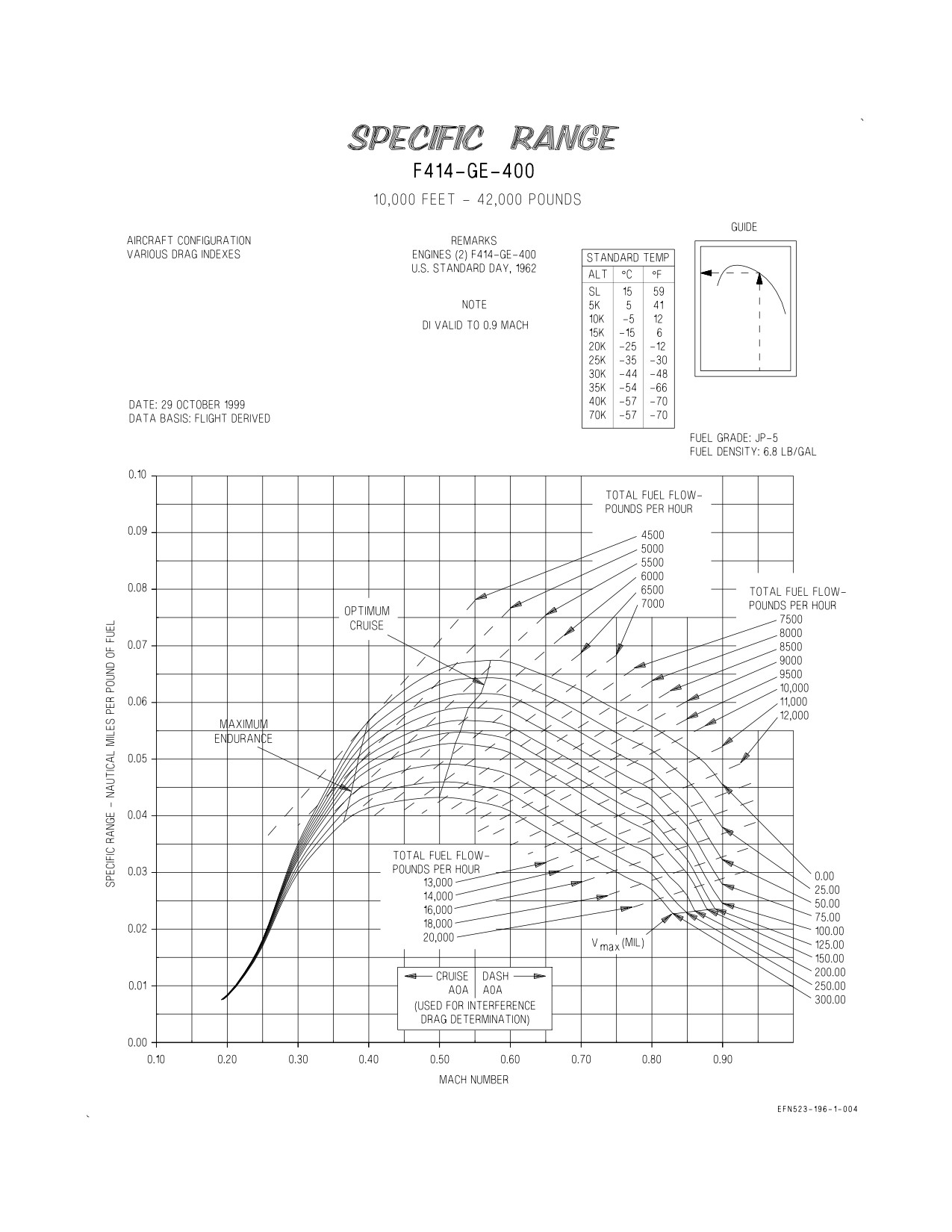
A1-F18EA-NFM-200
Figure 5-25. Specific Range - 10,000 Feet - 42,000 Pounds
XI-5-35
ORIGINAL
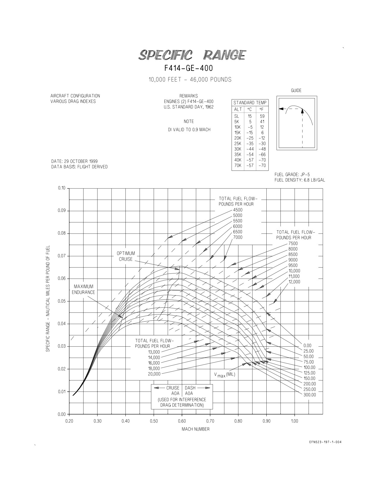
A1-F18EA-NFM-200
Figure 5-26. Specific Range - 10,000 Feet - 46,000 Pounds
XI-5-36
ORIGINAL
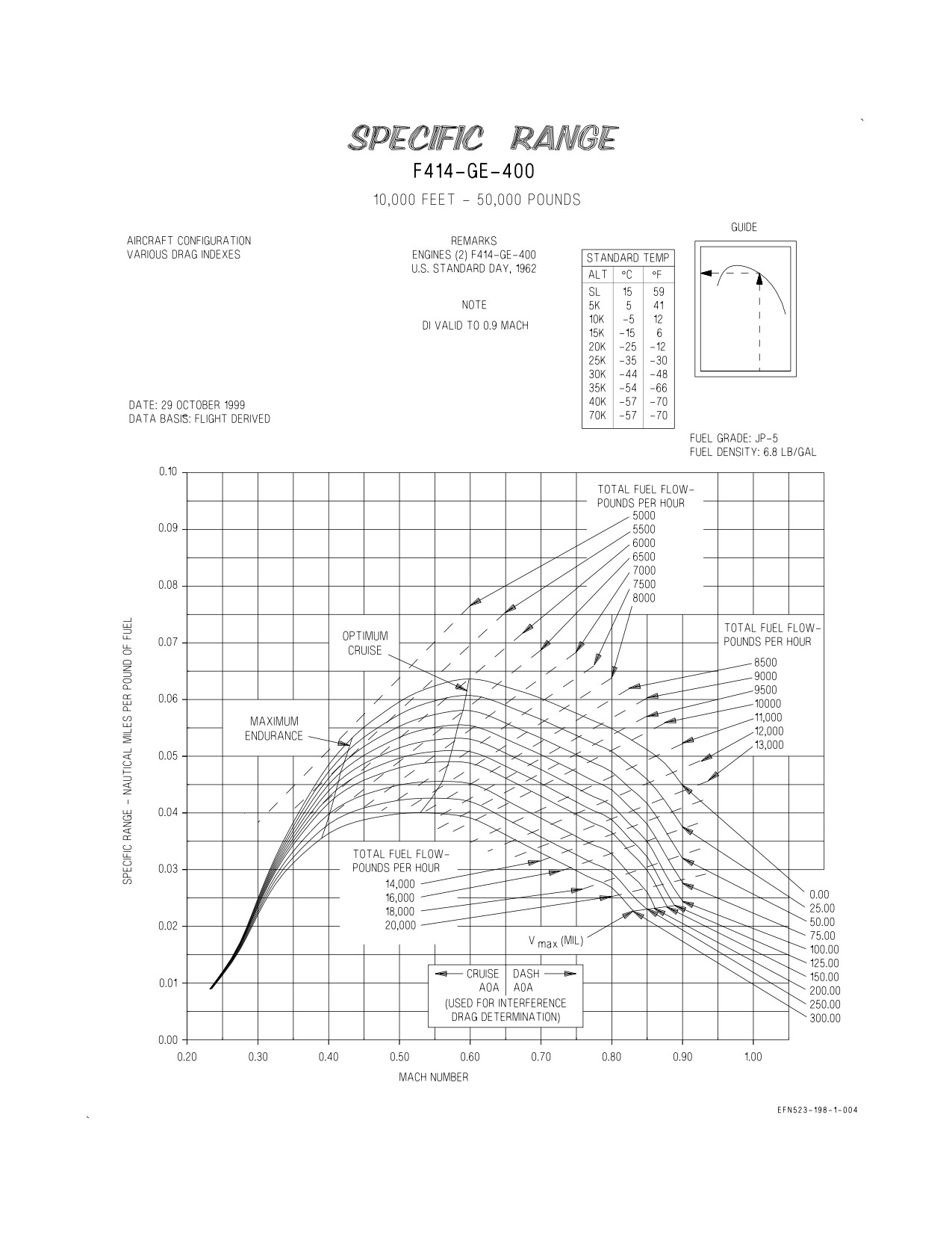
A1-F18EA-NFM-200
Figure 5-27. Specific Range - 10,000 Feet - 50,000 Pounds
XI-5-37
ORIGINAL
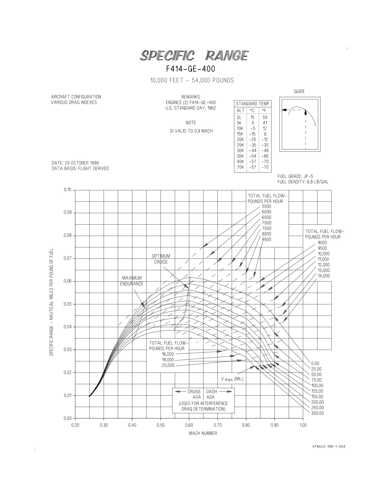
A1-F18EA-NFM-200
Figure 5-28. Specific Range - 10,000 Feet - 54,000 Pounds
XI-5-38
ORIGINAL
A1-F18EA-NFM-200
Figure 5-29. Specific Range - 10,000 Feet - 58,000 Pounds
XI-5-39
ORIGINAL
A1-F18EA-NFM-200
Figure 5-30. Specific Range - 10,000 Feet - 62,000 Pounds
XI-5-40
ORIGINAL
A1-F18EA-NFM-200
Figure 5-31. Specific Range - 10,000 Feet - 66,000 Pounds
XI-5-41
ORIGINAL
A1-F18EA-NFM-200
Figure 5-32. Specific Range - 15,000 Feet - 30,000 Pounds
XI-5-42
ORIGINAL
A1-F18EA-NFM-200
Figure 5-33. Specific Range - 15,000 Feet - 34,000 Pounds
XI-5-43
ORIGINAL
A1-F18EA-NFM-200
Figure 5-34. Specific Range - 15,000 Feet - 38,000 Pounds
XI-5-44
ORIGINAL
A1-F18EA-NFM-200
Figure 5-35. Specific Range - 15,000 Feet - 42,000 Pounds
XI-5-45
ORIGINAL
A1-F18EA-NFM-200
Figure 5-36. Specific Range - 15,000 Feet - 46,000 Pounds
XI-5-46
ORIGINAL
A1-F18EA-NFM-200
Figure 5-37. Specific Range - 15,000 Feet - 50,000 Pounds
XI-5-47
ORIGINAL
A1-F18EA-NFM-200
Figure 5-38. Specific Range - 15,000 Feet - 54,000 Pounds
XI-5-48
ORIGINAL
A1-F18EA-NFM-200
Figure 5-39. Specific Range - 15,000 Feet - 58,000 Pounds
XI-5-49
ORIGINAL