F18. FLIGHT MANUAL (2008) - page 22
A1-F18EA-NFM-000
29. HMD - ALIGN (both cockpits)
NOTE
Canopy must be down and locked to align HMD/AHMD.
(CVRS record HMD if desired)
a. SUPT/HMD/ALIGN page - SELECT
b. Superimpose the HMD alignment cross on the HUD/BRU alignment cross.
c. Cage/Uncage button - PRESS and HOLD until ALIGNING turns to ALIGN OK or ALIGN
FAIL
If ALIGN FAIL -
d. Repeat steps b and c.
If ALIGN OK and HMD alignment crosses are not coincident with HUD/BRU alignment cross -
d. Perform FINE ALIGN.
(1) With FA DXDY displayed, use TDC to align azimuth and elevation HMD alignment
crosses with the HUD/BRU alignment cross.
(2) Cage/Uncage button - PRESS and RELEASE
(3) With FA DROLL displayed, use TDC to align the roll axis HMD alignment crosses with the
HUD/BRU alignment cross.
(4) Cage/Uncage button - PRESS and RELEASE
If satisfied with alignment -
e. ALIGN - UNBOX
30. Standby attitude data - CHECK
a. ATT switch - STBY
b. Verify INS attitude data is replaced by standby
attitude data on the HUD and check
agreement of standby and INS data.
c. ATT switch - AUTO
31. OBOGS system - CHECK
a. OBOGS control switch - ON
b. OXY FLOW knob - ON/MASK ON (both cockpits)
c. OBOGS flow - CHECK
III-7-29
ORIGINAL
A1-F18EA-NFM-000
d. OBOGS monitor electronic BIT pushbutton - PRESS AND RELEASE
e. Verify OBOGS DEGD caution set and removed (within 15 seconds).
f. OXY FLOW knob - OFF/MASK OFF (both cockpits)
Continued operation and use of the OBOGS system with an OBOGS
DEGD caution may result in hypoxia.
7.4 TAXI CHECKS
1. Canopy - EITHER FULL UP OR FULL DOWN FOR TAXI
Taxiing with the canopy at an intermediate position can result in canopy
attach point damage and failure.
2. Normal brakes - CHECK
3. Nosewheel steering - CHECK IN HIGH MODE L/R
NOTE
When using brakes, apply firm, steady brake pedal pressure. Use
nosewheel steering whenever possible, minimizing differential braking.
Avoid dragging brakes or light brake applications except as necessary
for drying wet brakes. Wet brakes can degrade brake effectiveness by
as much as 50%. Hard momentary braking with wet brakes during taxi
can reduce drying time. At heavy gross weight, make all turns at
minimum speed and maximum practical radius.
7.5 TAKEOFF
7.5.1 Before Takeoff Checks.
For MAX power catapult launches -
1. ABLIM option - BOX
2. ABLIM advisory - VERIFY DISPLAYED
For all takeoffs -
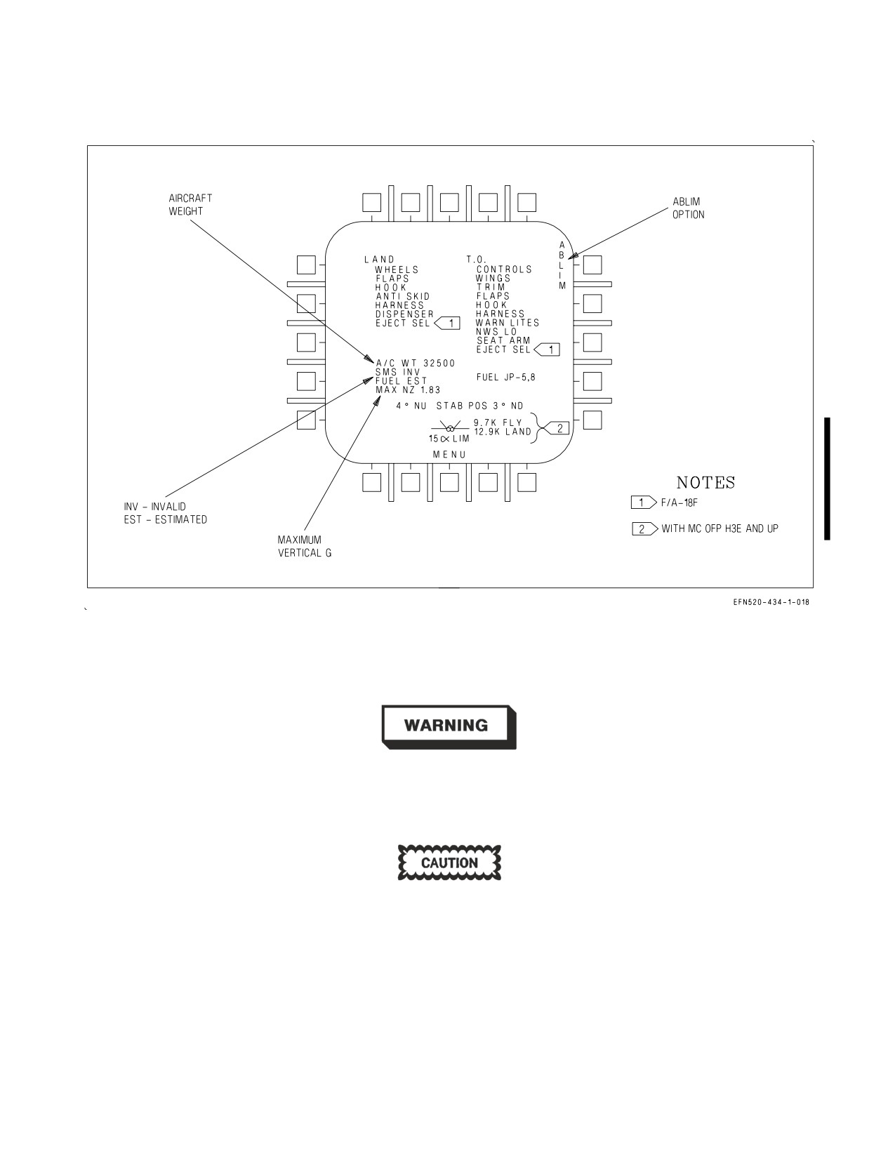
3. CHKLST page (figure 7-2)
a. FUEL TYPE - VERIFY
III-7-30
ORIGINAL
A1-F18EA-NFM-000
Figure 7-2. Checklist Display
b. T.O. checklist - COMPLETE
Ensure the WINGFOLD switch is lever-locked in the SPREAD position.
If the wings are commanded to unlock or fold during a catapult shot, the
wings will unlock, the ailerons will fair, the wings may fold partially, and
the aircraft will settle.
WSO must make sure the EJECTION MODE handle is in AFT INI-
TIATE (NORM) and, in Lot 21-24, aircraft the EMERG LDG GEAR and
EMERG BRK handles are fully stowed.
NOTE
EJECT SEL is displayed in the F/A-18F only.
III-7-31
ORIGINAL
A1-F18EA-NFM-000
NOTE
Rear cockpit command eject is enabled when the EJECTION MODE
handle is in the AFT INITIATE position. When a passenger unfamiliar
with the F/A-18F occupies the aft cockpit, the NORM position may be
utilized.
4. Canopy - CHECK CLEAR/CLOSED
Prior to operating the canopy switch, confirm aircrew are clear to reduce
the potential for injury.
5. OXY FLOW knob - ON/MASK ON (both cockpits)
It is possible to place the OXY FLOW knob in an intermediate position
between the ON and OFF detents, which may result in a reduced flow of
oxygen. The OXY FLOW knob should always be fully rotated to the ON
or OFF detent position.
6. IFF sublevel - BOX REQUIRED MODES
7. PARK BRK handle - FULLY STOWED
8. ENG page - CHECK ENGINES AT MIL (if desired)
N1 RPM
86 to 98%
N2 RPM
88 to 100%
EGT
720 to 932°C
FF
11,000 pph max
NOZ POS
0 to 45% open
OIL PRESS
80 to 150 psi
7.5.2
Normal Takeoff. Predictions for takeoff performance (nosewheel liftoff speed, takeoff speed,
takeoff distance, and abort speed) should be calculated in the preflight brief based on aircraft
configuration and expected ambient conditions. These predictions are based on the following
technique: both engines stabilized at 80%N2 rpm, simultaneous brake release and throttle advance to
MIL or MAX, ½-aft (2.5 inches) stick rotation at the predicted nosewheel liftoff speed. This technique
should be used when ambient conditions and performance predictions warrant minimizing takeoff roll.
Review these numbers prior to takeoff.
The takeoff checklist should be completed prior to taking the duty runway. For single-ship takeoffs,
taxi to runway centerline and allow the aircraft to roll forward slightly to center the nosewheel. Begin
the takeoff roll by releasing the brakes, advancing the throttles from IDLE to MIL, and checking EGT
and RPM. If an afterburner takeoff is desired, further advance the throttles to MAX (full forward).
Check for proper afterburner light-off as indicated by both nozzles opening. As the aircraft accelerates
during the takeoff roll, track runway centerline using small rudder pedal inputs
(e.g., NWS
commands). NWS is the most effective means of directional control during takeoff. Differential
III-7-32
ORIGINAL
A1-F18EA-NFM-000
braking is much less effective and should therefore be avoided. The NWS system (low gain)
incorporates a yaw rate feedback input from the FCCs, which is designed to suppress directional PIO
tendencies by increasing directional damping during takeoff.
At nominal takeoff CG, aft stick will be required to rotate the aircraft. Approaching the predicted
nosewheel liftoff speed, ease the stick back to approximately 1/3 to 1/2 aft stick (1-1/2 to 2-1/2 inches).
Hold this input until the velocity vector rises to approximately 3 to 5°. Capture and climb/accelerate
at the desired flight path angle.
When clear of the ground with a positive rate of climb, raise the LDG GEAR handle and place the
FLAP switch to AUTO. In a flat takeoff attitude with MAX power selected, the aircraft will accelerate
rapidly towards gear speed. If required, reduce power to MIL or below to ensure the landing gear is up
and locked (light in the LDG GEAR handle is out) before passing 250 KCAS.
Takeoff performance is greatly affected by gross weight, center of gravity,
power setting, stabilator position, and ambient conditions. Under adverse
conditions (e.g., hot, heavy, and forward CG), takeoff speeds may be
significantly higher than those routinely seen at nominal conditions.
Knowing the aircraft’s predicted takeoff performance should prevent a
high speed abort in what is a normally functioning aircraft.
III-7-33
ORIGINAL
A1-F18EA-NFM-000
• Under the most extreme conditions (e.g., hot, heavy, and forward CG),
nosewheel liftoff speed may exceed the nose tire limitation (195 KGS).
The takeoff technique and/or the aircraft configuration may need to
be adjusted to remain within limitations.
• Large aft stick inputs, particularly with CG near the aft limit, can
result in significant over-rotation. With pitch attitude above 10°, the
trailing edge of the stabilators can impact the ground if a large forward
stick input is used to check the over-rotation. Above
14° pitch
attitude, the engine exhaust nozzles may contact the ground. There-
fore, pitch attitude shall not exceed 10° on takeoff.
• Takeoff with significant standing water (greater than 1/4 inch) on the
runway may cause water ingestion, which in extreme cases can cause
engine stalls, flameouts, AB blowouts, and/or engine FOD.
7.5.3 Crosswind Takeoff. Crosswind takeoffs should be performed using the normal takeoff tech-
nique. However, the pilot should expect to make slightly larger and more frequent rudder pedal inputs
to track runway centerline. As the aircraft accelerates and the ailerons become effective, lateral stick
into the wind may be desired to maintain wings level throughout the remainder of the takeoff roll and
rotation. As the aircraft becomes light on the main wheels, the aircraft will tend to yaw into the wind.
Slight main tire scrubbing can be expected. Allow the aircraft to crab into the wind at takeoff, while
continuing to maintain runway centerline during the gear transition and early climbout.
When calculating crosswind component for takeoff or landing, use the full
value of any reported gusts in your calculations.
7.5.4 After Takeoff Checks.
When definitely airborne -
1. LDG GEAR handle - UP
2. FLAP switch - AUTO
7.6 AIRBORNE CHECKS
7.6.1 Climb. For safe maneuverability of the aircraft, up to 350 KCAS may be required up to 10,000
feet. For optimum climb performance, refer to A1-F18EA-NFM-200.
7.6.2 10,000 Foot Checks.
1. Cabin altimeter - VERIFY 8,000 FEET
2. Fuel transfer - CHECK INTERNAL and EXTERNAL
III-7-34
ORIGINAL
A1-F18EA-NFM-000
3. RALT - CHECK/SET to 5,000 FEET
7.6.3 Cruise. Maximum range and maximum endurance data can be found in the performance charts
contained in A1-F18EA-NFM-200. Maximum range cruise is approximated by establishing 3.0° AOA,
but no faster than Mach 0.85. Maximum endurance cruise is approximated by establishing 3.7° AOA.
7.6.3.1
Cruise Check.
1. Cabin altimeter - MONITOR
Aircraft Altitude
Cabin Altitude
Less than 8,000 feet
Ambient
8,000 to 24,500 feet
8,000 feet
Greater than 24,500 feet
Alt x 0.4 (rule of thumb)
A slowly increasing cabin pressure altimeter may be the first or only
warning of a gradual loss of cabin pressurization.
7.6.3.2
RVSM Checks
When at assigned altitude on HUD -
1. AOA Crosscheck (REQUIRED ONCE)
a. Compare L and R AOA values on FCS page.
b. If L and R AOA values differ by more than 2°, notify ATC that the aircraft is no longer RVSM
compliant.
2. Altitude Crosscheck (REQUIRED PERIODICALLY)
With MC OFP H5E AND UP -
a. Compare STBY CHK value (HSI/DATA/(A/C)) to standby altimeter. These are uncorrected
altitudes.
Otherwise -
a. Add standby altimeter error (Standby Altimeter Error table below) to standby altimeter and
compare to HUD altitude.
All aircraft -
b. If altitudes differ by more than 250 feet, notify ATC that the aircraft is no longer RVSM
compliant.
c. If an ″X″ appears to the right of the HUD baro altitude box, notify ATC that the aircraft is no
longer RVSM compliant.
III-7-35
ORIGINAL
A1-F18EA-NFM-000
Standby Altimeter Error
Mach Number
Standby Altimeter Error (Feet)
0.50
120
0.60
150
0.65
175
0.70
200
0.75
220
0.80
280
0.85
260
0.90
330
0.92
380
7.7 LANDING CHECKS
7.7.1 Descent/Penetration. The windshield may fog rapidly under conditions of very high aircraft
descent rates and high humidity. In such conditions, consider preheating the windshield by placing the
DEFOG handle to HIGH and, if necessary, by placing the WINDSHIELD switch to either ANTI ICE
or RAIN. The maximum comfortable cockpit temperature should be maintained to aid in windshield
defog.
Normal instrument penetration is 250 KCAS with a 4,000 to 6,000 feet per minute descent rate. For
safe maneuverability of the aircraft, up to 350 KCAS may be required below 10,000 feet. Refer to
A1-F18EA-NFM-200, for optimum descent profiles. Before starting descent, perform the following:
7.7.1.1
Descent/Penetration Checks.
1. HOOK handle/HOOK BYPASS switch - AS REQUIRED/DESIRED
2. Exterior lights - SET FOR LANDING
3. Visual ID IDENT knob - NORM
4. ENG ANTI ICE switch - AS REQUIRED
5. PITOT ANTI ICE switch - AUTO
6. DEFOG handle - HIGH (if required)
7. WINDSHIELD switch - AS REQUIRED
8. Altimeter setting - CHECK
III-7-36
ORIGINAL
A1-F18EA-NFM-000
9. RALT - CHECK/SET
10. NAV master mode - SELECT (compare HUD with standby flight instruments and standby
compass).
11. Navaids/MAG VAR - CROSSCHECK
12. ILS - ON/CHANNEL SET (if required)
13. IFF - AS DIRECTED
III-7-37
ORIGINAL
A1-F18EA-NFM-000
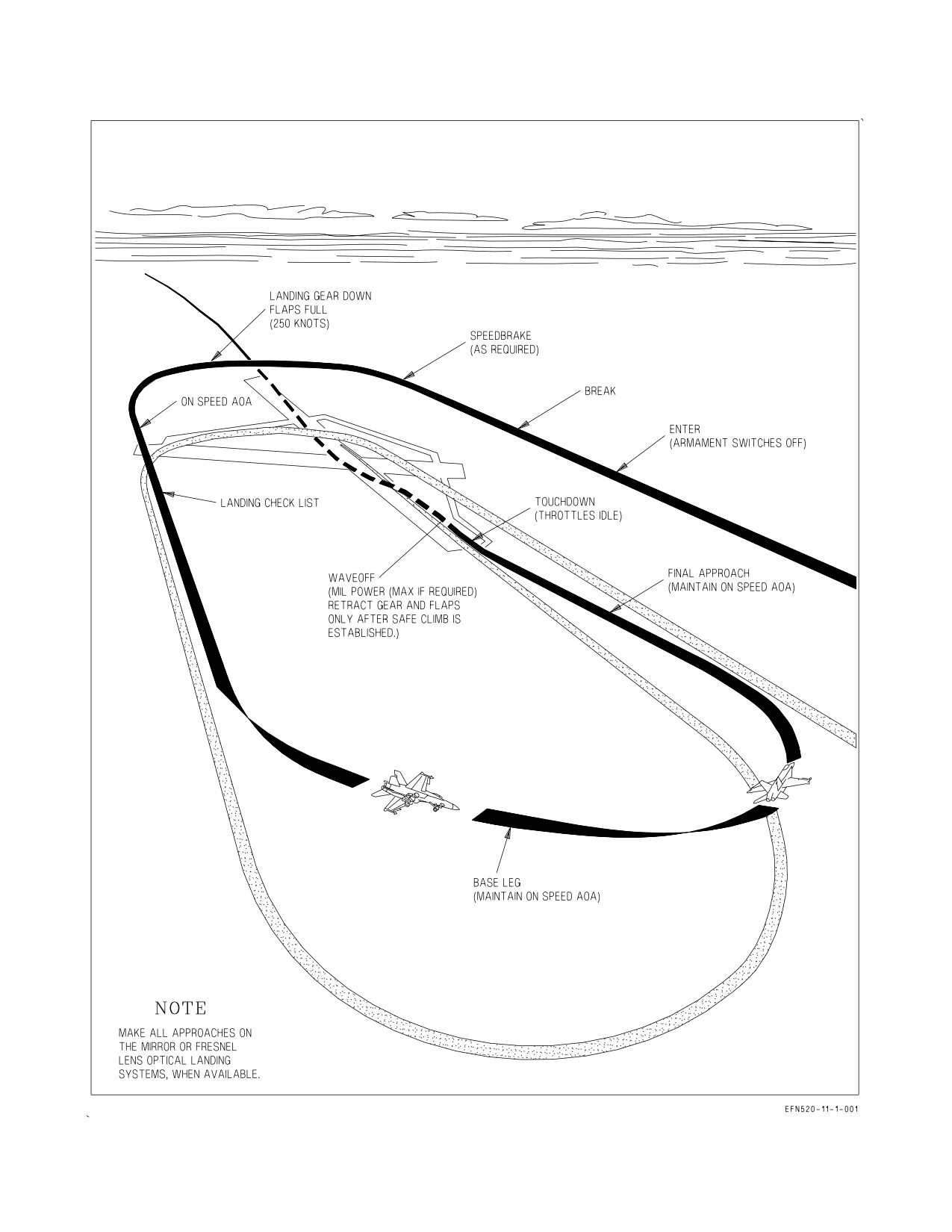
Figure 7-3. Typical Field Landing Pattern
III-7-38
ORIGINAL
A1-F18EA-NFM-000
14. Weapons/sensors - OFF AS REQUIRED
7.7.2 VFR Landing Pattern Entry. See figure 7-3. Typically, the VFR landing pattern can be entered through
several methods: the break, downwind entry, VFR straight-in, or low approach/touch-and-go from a GCA.
Regardless of the entry method, enter the pattern at the altitudes and airspeeds prescribed by local course rules.
A normal break is performed by executing a level turn to downwind with the throttles reduced to IDLE and the
speedbrake function enabled (if required to reduce airspeed). The desired abeam distance is 1.0 to 1.3 nm. The
g-level required to achieve the desired abeam distance will be a fallout of break airspeed.
As airspeed decelerates below 250 KCAS, lower the LDG GEAR handle and place the FLAP switch to FULL.
If enabled, the speedbrake function will retract automatically when the FLAP switch is moved from the AUTO
position. Continue to decelerate to on-speed AOA (8.1 deg). Longitudinal trim inputs are required with the flaps
in HALF or FULL. The MI code for on-speed AOA is unit 14, address 15743, data 3300.
In-flight Memory Inspect (MI) of FCC (UNIT 14 or 15) addresses (ADDR)
greater than six digits long is prohibited since it may cause all four FCC channels
to shut down which will result in loss of aircraft control.
With MC OFP H3E AND UP, the pitch trim AOA value is displayed on the HUD while trimming and for two
seconds after trimming, and continuously on the FCS page with WoffW and flaps in HALF or FULL. The HUD
value is displayed with or without ATC engaged but will not be displayed with autopilot engaged. If the autopilot
is ″paddled off″ and AOA is greater than or equal to 6°, pitch trim is automatically set to on-speed. Trim the
aircraft hands-off and on-speed. Compare airspeed and AOA. Onspeed AOA is approximately 136 KCAS at
44,000 lb gross weight (max trap). Subtract (add) 1½ KCAS for each 1,000 lb decrease (increase) in gross weight.
Complete the landing checklist. When wings level on downwind, descend to pattern altitude (600 ft AGL for the
low pattern). Ensure the ground track pointer is on the exact reciprocal of runway heading.
7.7.2.1
Landing Checks.
1. Landing checklist - COMPLETE:
WHEELS
FLAPS
HOOK
ANTI SKID
HARNESS
DISPENSER
EJECT SEL
AOA
2. Report - AFT INITIATE, 3 DOWN AND LOCKED, FLAPS FULL (HALF), AOA CROSS-
CHECKED
7.7.3 VFR Landing Pattern and Approach. At the abeam position, pick a spot on the ground as a reference
point. (At the ship, TACAN will be used to adjust abeam distance). Remember this abeam position, as all abeam
distance corrections will use it as a reference. From the abeam position, time 20 seconds to arrive at a no-wind
180° position. To compensate for winds, subtract one second for each knot of final approach headwind
component. At the 180, roll into 27 - 30° AOB, add power, and adjust rate of descent to 300 to 400 fpm. Maintain
on-speed AOA. This should place the velocity vector about 1° below the horizon with its wingtip below the
horizon bar. If required, adjust rate of descent to arrive at the 90° position at 450 ft AGL. Develop an instrument
scan for the turn from the 180 to the 90, because an instrument scan will be required at the ship.
At the 90, glance at runway centerline and the lens and adjust AOB to arrive on extended centerline.
From the 90, rate of descent must be increased by reducing power and adjusting the velocity vector to
1½ to 2° below the horizon, on-speed. This will produce a rate of descent of 400 to 500 fpm to arrive
III-7-39
ORIGINAL W/IC 34
A1-F18EA-NFM-000
at the 45° position at 320-370 feet AGL. From the 45, continue to increase rate of descent to
approximately 500-600 fpm with a power reduction to arrive at ″the start″ on centerline, at 220 to 250
feet AGL, with 650 to 750 fpm rate of descent, on-speed. The optimum rate of descent will vary with
glideslope angle, approach speed, and headwind component.
The approach turn from a pattern altitude greater than 600 ft AGL is slightly different. At the 180,
adjust rate of descent between 400 - 700 fpm to arrive at the 90 at approximately 500 ft AGL. This
requires a power reduction at the 180 rather than a power addition. Power will need to be added at the
90 to break the rate of descent to 400 to 500 fpm in order to arrive at the 45 at the same flight conditions
as the low pattern.
7.7.4 Pattern Adjustments. Deviations to the standard no-wind pattern will be required based on
headwind, crosswind, approach speed, and starts by adjusting abeam distance. Adjust the ground
reference point and fly exactly the same AOB as the previous pass. Correct for long-in-the-groove or
not-enough-straight-away starts by adjusting the timing from the abeam to 180° positions. Correct for
high or low starts by adding or subtracting 20 to 50 feet from the target altitudes at and inside of the
90. The purpose of pattern adjustments is to determine a repeatable pattern technique which will
produce consistent starts.
7.7.5 Final Approach. The desired final approach is flown by maintaining a centered ball to
touchdown on runway centerline and on-speed. Timely, well-controlled power corrections will be
required to capture and/or maintain the desired glideslope. A complete discussion of glideslope
geometry and glideslope corrections will be covered during the FRS training syllabus and/or by
squadron LSOs.
7.7.6 ATC Approaches. If an ATC approach is desired, engage ATC when wings level on downwind
at or near on-speed AOA. With ATC engaged, the aircraft must still be manually trimmed to on-speed
AOA. Unlike a manual throttles approach, nose position (i.e., velocity vector placement) now controls
power. Fly the same pattern as a manual approach. Coming off the 180, roll into 27 to 30° AOB and
lower the velocity vector approximately 1 to 2° below the horizon. ATC will add power as the aircraft
rolls into the turn. Reposition the velocity vector to maintain 300 to 400 fpm rate of descent. Passing
through the 90, lower the velocity vector slightly to pick up a 400 to 500 fpm rate of descent. Rolling
wings level in the groove, lower the velocity vector further to about 3°. Power corrections required to
adjust glideslope are made by repositioning the velocity vector with forward or aft stick inputs. For best
results, make small corrections in velocity vector placement and be smooth. Avoid large, rapid, cyclic
stick motion or ″stick pumping″ as these inputs can produce a PIO with the autothrottles.
Although ATC is capable of handling almost all glideslope corrections, the stick inputs required to
successfully correct large deviations can be difficult to make. In general, if the ball is more than 1 ball
from the center, consider disengaging ATC and executing a manual pass.
7.7.7 FPAH/ROLL - ATC Approaches. The FPAH/ROLL autopilot mode, when utilized with ATC,
provides an alternative method for landing the aircraft. The FPAH/ROLL mode is designed to reduce
pilot workload by maintaining flight path angle (FPA) and roll attitude. When the velocity vector is
positioned as desired and the stick is neutralized, the autopilot maintains the current FPA and roll
attitude, making corrections for wind gusts or disturbances as required. Repositioning the velocity
vector with longitudinal or lateral stick inputs changes the reference FPA and/or roll attitude that the
autopilot holds when the stick is released. In FPAH/ROLL, aircraft response to longitudinal stick
inputs is slightly sluggish compared to CAS while response to lateral stick inputs is essentially the
same.
III-7-40
ORIGINAL
A1-F18EA-NFM-000
Once the velocity vector is placed in the desired position, the stick is neutralized, and the pilot
essentially monitors autopilot progress. Corrections should be small and applied only when required.
Learning to make appropriate corrections and to stay out-of-the-loop when corrections are not
required takes practice to achieve good results. With practice, smooth, consistent landings can be
achieved even in gusty wind conditions.
NOTE
Use of FPAH/ROLL without ATC may result in more difficult AOA
control and is not recommended.
7.7.7.1
FPAH/ROLL - ATC Approach Technique (field only). If an FPAH/ROLL - ATC approach is
desired, engage ATC when wings level on downwind and trim for on-speed AOA. Select FPAH/ROLL
from the A/P sublevel on the UFCD, and ensure both modes are boxed.
Fly the standard landing pattern utilizing the numbers and velocity vector positioning described in
the ATC Approaches paragraph. A push and roll is required to establish the approach turn. Once the
velocity vector is positioned, neutralize the stick and monitor autopilot progress. No back stick should
be required in the turn. Passing through the 90 and approaching the start, push forward stick to lower
the velocity vector and establish the desired rate of descent and then neutralize the stick. If on
glideslope, roll wings level in the groove using only lateral stick inputs. Longitudinal stick inputs should
not be required, as the autopilot compensates automatically to maintain FPA. Similarly, if on
glideslope, make lineup corrections solely with lateral stick.
If the ball is not centered, adjust the velocity vector (i.e., reference FPA) up or down accordingly and
allow the autopilot to fly the aircraft back to glideslope. Approaching a centered ball, adjust the
velocity vector to the desired flightpath and neutralize the stick. The autopilot should then maintain
FPA (ideally a centered ball) and compensate automatically for gusts. Make corrections with small,
discrete longitudinal stick inputs and evaluate the correction before applying another. If the ball is
centered and stable, the system works best if longitudinal inputs are minimized. There may be
noticeable pitch motion, similar to what is seen on a Mode-1 ACLS approach, as the airplane responds
to gusts, but FPA should be stable.
FPAH/ROLL is less capable at handling large deviations than CAS - ATC. In general, if the ball is
more than 1 ball from the center, consider disengaging FPAH/ROLL with the paddle switch and
executing an ATC or manual pass.
7.7.8 Full Stop Landings. Maintain approach rate of descent and power setting by flying a centered
ball to touchdown or by placing the velocity vector at least 500 feet past the runway threshold. After
touchdown, place the throttles to IDLE and track runway centerline using small rudder pedal inputs.
The engines will not select ground idle until the aircraft has decelerated below 80 KCAS. While the
rudders are effective above 100 KCAS, NWS is the most effective means of directionally controlling the
aircraft during landing rollout. Low gain NWS is activated automatically at touchdown with weight on
III-7-41
ORIGINAL
A1-F18EA-NFM-000
the nose landing gear and at least one main landing gear. Differential braking to maintain directional
control is not as effective and should normally be avoided.
Use of NWS HI during landing rollout is not recommended, as it may
lead to directional PIO due to the increased sensitivity of the NWS
system to rudder pedal inputs.
Engaging NWS HI while maintaining a rudder pedal input will greatly
increase nosewheel deflection and may cause loss of directional control.
7.7.9 Braking Technique. Under normal circumstances, the best results are attained by applying
moderate to heavy braking with one smooth application of increasing braking pressure as airspeed
decelerates towards taxi speed. Anti-skid is effective down to approximately 40 KGS. Below 40 KGS,
heavy brake pedal pressure should be relaxed to prevent tire skid. Below 35 KGS, steady but firm
brake pedal pressure should be applied. Steady, light brake applications should be avoided, as they
increase brake heating, do not significantly contribute to deceleration, and ultimately reduce braking
effectiveness. If desired, selecting aft stick (up to full) below 100 KCAS will increase TEU stabilator
deflection and aid in deceleration. Full aft stick increases down force on the main landing gear, as well
as significantly increasing drag due to large stabilator size.
Recommended braking speeds are based on tests conducted at sea level.
Ground speed may be significantly higher than calibrated airspeed at
airfields above sea level. Aircrew should consider available runway length
and field elevation to evaluate wheel brake usage and landing rollout
distance to avoid excessive brake heat build up and subsequent tire
deflation or wheel assembly fire when landing at airfields above sea level.
Maximum braking performance is attained by applying full brake pedal pressure (approximately 125
lb) immediately after touchdown. Anti-skid must be on to attain maximum braking performance and
to reduce the risk of a blown tire. Longitudinal pulsing may be felt as the anti-skid cycles. Approaching
40 KCAS, full brake pedal pressure should be relaxed to prevent tire skid.
7.7.9.1
Aerobraking Technique. Aerobraking is not required under most circumstances. However,
aerobraking is an effective method to slow heavy gross weight aircraft with a reduced risk of hot brakes
and fire, or to slow aircraft on wet runways. Aerobraking is authorized under the following conditions:
a. Crosswind 5 knots or less
b. Pitch attitude 10° or less
c. Greater than 80 KCAS
d. GAIN ORIDE not selected
e. No FCS AIR DAT or FLAP SCHED cautions
III-7-42
ORIGINAL
A1-F18EA-NFM-000
f. Flap position not changed during aerobraking
After main landing gear touchdown, smoothly apply aft stick to capture a positive pitch attitude
with the waterline, not to exceed 10°. Directional control can be maintained with rudder pedal inputs
and wings can be leveled with lateral stick. At approximately 100 KCAS, center rudder pedals and
smoothly relax aft stick to allow the nose of the aircraft to fall. Avoid abrupt forward stick inputs to
derotate. Once the nosewheel is on the ground, proceed with normal braking technique. Stopping
distance using aerobraking should be approximately that experienced during normal braking.
Large, abrupt aft stick inputs, particularly with CG near the aft limit, can
result in significant over−rotation. With pitch attitude over 10°, the
trailing edge of the stabilators can impact the ground if a full forward
stick input is used to check the over-rotation. Above 14° pitch attitude,
the raised hook point or engine exhaust nozzles may contact the ground.
Therefore, pitch attitude shall not exceed 10° during aerobraking and
abrupt forward stick inputs to derotate should be avoided.
NOTE
Landing distance data in Chapter XI and the PCL are calculated on
maximum braking performance technique listed above. The effect of
aerobraking is not accounted for in the braking distance performance
charts.
7.7.10 Heavy Gross Weight Landings. The aircraft’s 50,600 lb GW field landing limitation provides
the capability to land with a significant amount of fuel and/or stores (approximately 16,000 lb of
bringback). Landing at heavy gross weight, however, requires that the pilot pay particular attention to
braking technique and overall brake usage to avoid excessive brake and wheel assembly heating, melted
fuse plugs, and deflated tires. The wheel assembly fuse plugs are designed to melt and deflate the tires
at temperatures below those which would result in catastrophic tire blowouts. Wheel assembly
temperatures do not, however, reach their peak until approximately 20 minutes after landing, e.g., it
takes 20 minutes for the heat (energy) imparted to the brake assembly at landing to transfer into the
wheel assembly. Due to this slow transfer of heat, it is not uncommon for an aircraft to pass a post flight
hot brakes check yet still melt a fuse plug in the line.
In general, the aircraft’s braking system is designed for landing under the following circumstances
without melting a fuse plug: land at 50,600 lb GW, maximum anti-skid braking at 115 KCAS, three taxi
stops from 30 KGS, park for 15 minutes, three more taxi stops from 30 KGS. If overall brake usage
exceeds these criteria, melted fuse plugs and deflated tires may result. Below approximately 46,000 lb
GW, brake usage following a maximum anti-skid landing (at or below 90%of approach speed) should
be unlimited. Therefore, any landing above 46,000 lb GW should be considered a heavy gross weight
landing.
7.7.10.1 Heavy Gross Weight Braking Technique. Above 46,000 lb GW, delay the initial brake
application to 115 KCAS or lower, if possible. Utilize aerobraking if desired and runway length is not
a factor, otherwise normal braking technique or maximum anti-skid braking is acceptable. Release the
brakes when desired taxi speed is reached. When clear of the runway, make a conscious effort to limit
taxi speed and minimize brake applications, particularly if maximum anti-skid braking was utilized. If
III-7-43
ORIGINAL
A1-F18EA-NFM-000
overall brake usage is extensive, consider chocking the wheels and leaving the parking brake off to aid
in brake cooling and to limit the amount of heat transferred to the wheel assembly.
Recommended braking speeds are based on tests conducted at sea level.
Ground speed may be significantly higher than calibrated airspeed at
airfields above sea level. Aircrew should consider field elevation when
determining the calibrated airspeed at which brakes will be applied to
avoid excessive brake heat build up and subsequent tire delflation or
wheel assembly fire.
7.7.11 Crosswind Landings. During flight test, three crosswind landing techniques were evaluated:
full-crab-to-touchdown, half-crab-kickout, and wing-down-top-rudder. In general, the half-crab-
kickout technique works best and is recommended for all crosswinds up to 30 knots; the full-crab-to-
touchdown technique is acceptable for moderate crosswinds only; and the wing-down-top-rudder
technique is not recommended.
When calculating crosswind component for takeoff or landing, use the full
value of any reported gusts in your calculations.
7.7.11.1 Half-Crab Kickout Technique. In crosswinds up to 30 knots, best crosswind landing results
are attained by performing a half-crab-kickout technique. This technique reduces lateral and
directional oscillations after touchdown and minimizes landing gear side loads.
Fly a full crab approach (wings level, neutral pedals) to approximately 50 feet AGL. Immediately
prior to touchdown, apply one smooth rudder pedal input to ″kick out″ half of the crab angle. Maintain
wings level. Allow the initial directional oscillations to subside, then utilize the normal braking
technique. Stabilator braking with up to full aft stick does not degrade directional control and may be
used to aid deceleration. Lateral stick into the wind will be required and is recommended to maintain
wings level during landing rollout.
Avoid removing half the crab angle too early or removing more than half of the crab angle. This may
cause the aircraft to drift downwind prior to touchdown and increases directional transients after
landing.
7.7.11.2 Full-Crab-to-Touchdown Technique. The landing gear is capable of absorbing the sideloads
imparted during a full-crab-to-touchdown landing in crosswinds up to
30 knots. However, in
crosswinds above approximately 15 knots, the aircraft response produced by this technique can be
uncomfortable. When the main gear contact the ground, the aircraft swerves downwind to align with
the runway and rolls away from the crosswind and into the runway. This roll excursion can be as much
as 8°. Two to three directional oscillations can be expected before the aircraft settles out and tracks
straight. While this motion is controllable, lateral stick inputs to level the wings must be timely, and
rudder pedal inputs must be judicious to control the directional transients. For this reason, a
full-crab-to-touchdown technique is not recommended in crosswinds over 15 knots.
In crosswinds below 15 knots, the roll into the runway and ensuing directional oscillations are small,
and the aircraft tends to track straight soon after touchdown. Fly a full-crab approach (wings level,
III-7-44
ORIGINAL
A1-F18EA-NFM-000
neutral pedals) all the way to touchdown. Apply lateral stick to keep the wings level, allow the small,
initial directional oscillations to subside, and then utilize the normal braking technique.
7.7.11.3 Wing-Down-Top-Rudder Technique. Even in light to moderate crosswinds, a wing-down-
top-rudder approach requires up to full rudder pedal displacement and an excessive bank angle (as
much as 10°) to balance the aircraft with no drift. Landing in this attitude is uncomfortable and should
be avoided. Additionally, any rudder pedal input applied at touchdown produces a large directional
excursion when NWS automatically engages. For these reasons, a wing-down-top-rudder technique is
not recommended.
7.7.12 Wet Runway Landings. Wet runway conditions can induce hydroplaning during landing
rollout. The minimum total hydroplaning speeds of the main landing gear tires (280 psi) and the nose
landing gear tires (150 psi) are 150 KGS and 110 KGS, respectively. Depending on runway conditions,
partial hydroplaning can occur at much lower speeds. If the nose tires are hydroplaning, the aircraft
may respond sluggishly to initial NWS commands. Under such circumstances, increasing rudder pedal
inputs may cause directional excursions when nose tire contact is established. If hydroplaning is
suspected, rudder pedal inputs should be kept as small as practicable.
For wet (standing water) runway conditions, reduce gross weight to the minimum practical. Land
on-speed or slightly slow with the power reduced to idle as soon as possible. Maintaining a constant
attitude and sink rate will help dissipate aircraft energy at touchdown. If directional control is
questionable, do not hesitate to add power, go around, and set up for an arrested landing. If directional
control is comfortable, use maximum anti-skid braking to minimize landing distance.
7.7.13 Asymmetric Stores Landings. The maximum lateral stores asymmetry for field landings is
29,000 ft-lb. For non-crosswind landings, the aircraft handles very much like a symmetrically loaded
aircraft. Trim the aircraft for wings level flight and fly a normal on-speed approach to touchdown.
During periods of moderate to heavy braking, expect the heavy wing to yaw forward. While easily
controlled with small rudder pedal inputs, this motion should be anticipated and countered quickly to
prevent a build up in yaw rate. Best results are attained by judiciously tracking runway centerline with
timely rudder pedal inputs.
For crosswind landings, use the half-crab kickout technique recommended for normal crosswind
landings. At touchdown, expect a slightly larger roll away from the crosswind and into the runway only
if the wind is into the light wing. Lateral stick into the wind will be required and is recommended to
maintain wings level during crosswind landing rollout, particularly when the wind is into the light wing.
Using this technique, asymmetric landings up to 29,000 ft-lb can be safely executed on a normal
3.25° glideslope up to 50,600 lb gross weight and in a 30 knot crosswind.
7.8
POST-FLIGHT CHECKS
7.8.1
After Landing. Do not taxi with the right engine shut down, as normal brakes and NWS are not
available.
7.8.1.1
After Landing Checks.
When clear of active runway -
1. Ejection seat SAFE/ARMED handle(s) - SAFE (confirm status in both cockpits)
III-7-45
ORIGINAL
A1-F18EA-NFM-000
2. EJECTION MODE handle - NORM
Make sure the ejection seat SAFE/ARMED handle is locked in the SAFE
position detent and that the word SAFE is completely visible on the
inboard side of the handle. If the handle will not lock in the detent or the
word SAFE is not completely visible, check to ensure that the ejection
control handle is fully stowed and attempt to resafe the seat. If unable to
properly safe the ejection seat, instruct line personnel to remain clear of
the cockpit until the seat is checked by qualified maintenance personnel.
3. Landing gear handle mechanical stop - CHECK FULLY ENGAGED
If the DOWNLOCK ORIDE button is pressed or the mechanical stop is
not fully engaged, the LDG GEAR handle can be raised on the ground,
and the main landing gear will retract.
4. FLAP switch - AUTO
5. T/O TRIM button - PRESS UNTIL TRIM ADVISORY DISPLAYED
6. Mask - OFF (confirm status both cockpits)
7. OBOGS system - SECURE
a. OXY FLOW knob - OFF (both cockpits)
b. OBOGS control switch - OFF
8. Canopy - EITHER FULL UP OR FULL DOWN FOR TAXI
• Taxiing with canopy at an intermediate position can result in canopy
attach point damage and failure.
• Prior to operating the canopy switch, confirm aircrew are clear and all
loose equipment is stowed to reduce the potential for injury and/or
III-7-46
ORIGINAL
A1-F18EA-NFM-000
engine FOD.
NOTE
Once the ejection seat(s) are confirmed SAFE and the EJECTION
MODE handle is in the NORM position, it is safe to unstrap.
Adjusting seat height after the upper Koch fittings are removed may
damage the ejection seat trombone fittings.
7.8.2 Hot Refueling. When hot refueling for a subsequent flight, the RADAR switch may be left in
OPR or STBY. However, if feed tank fuel temperatures are approaching their 79°C limit, consider
turning off the radar to aid in RLCS/fuel cooling.
Hot refueling must be performed with the canopy closed. Expect the REFUEL DR caution to be
displayed when ground crew open door 8R to expose the single point refueling receptacle. If refueling
of external tanks is not desired, the appropriate EXT TANKS switches must be placed to STOP.
Otherwise, hot refueling through the single point receptacle will fill all internal and external tanks.
NOTE
When hot refueling in Lots
21
thru
25, the IFR probe must be
extended to refuel any external fuel tanks loaded on the inboard
stations (4 and 8) when external fuel tanks are loaded on the midboard
stations (3 and 9).
The EFD and/or FUEL display can be referenced to monitor refueling progress. Expect external
tanks to refuel slowly until the internal tanks are full.
If an internal tank refuel valve has failed or is leaking, that tank will overfill and direct fuel into the
aircraft vent system. If the aircraft vent tanks overflow, fuel will spill from the vertical tail vent outlets.
When hot refueling is complete, ensure that the fuel cap is properly installed and door 8R is closed:
the REFUEL DR caution should be out and the plane captain/final checker shall give the confirmation
signal. This signal is a cupped, open hand rotated counterclockwise then clockwise followed by a
thumbs up.
For a subsequent flight, expect final checks prior to taxi for takeoff. If placed to OFF prior to
refueling, the RADAR switch may be reselected to OPR when refueling is complete.
A failed or leaking refuel valve can cause rapid overfilling of the aircraft
vent system, fuel spillage from the vent outlet(s), and possible fire if fuel
spills on hot engine components. If this occurs, discontinue hot refueling
immediately.
7.8.3 Before Engine Shutdown Checks.
1. PARK BRK handle - SET
2. BIT display - RECORD DEGD/FAIL INDICATIONS
III-7-47
ORIGINAL
A1-F18EA-NFM-000
3. Radar maintenance (BOA) codes - RECORD IF PRESENT
4. RADAR knob - OFF
5. FCS display - RECORD BLIN CODES
6. EFD - RECORD MSP CODES
7. INS - PERFORM POST FLIGHT UPDATE (if desired)
8. INS knob - OFF
9. Standby attitude reference indicator - CAGE (both cockpits)
10. HMD switch - OFF (both cockpits)
11. CRYPTO switch - AS REQUIRED
NOTE
Ensure the MIDS terminal is on, by ensuring L16 or TACAN is ON,
prior to any attempt to zeroize IFF Mode 4 Crypto Keys via the
CRYPTO switch.
12. Sensors, avionics, and CVRS - OFF
NOTE
The aircraft incorporates an avionics auto-shutdown feature which
powers down all UFCD controlled avionics when both throttles are
secured (ac power removed). Therefore, UFCD controlled avionics do
not need to be secured prior to shutdown.
13. EXT and INTR LT knobs - OFF (both cockpits)
14. Canopy - CHECK CLEAR/OPEN
III-7-48
ORIGINAL
A1-F18EA-NFM-000
A high voltage (100,000 volt) static electrical charge may build up inflight
and be stored in the windscreen and canopy. If possible, ensure that
ground crew discharge the static electricity prior to egress. Otherwise,
avoid direct contact with the outside of the windscreen and canopy to
prevent electrical shock.
15. QDC - DISCONNECTED AND STOWED
Failure to disconnect QDC prior to pilot egress will damage the lower IRC
connection.
7.8.4 Engine Shutdown Checks.
1. Brake accumulator gauge - CONFIRM 3,000 PSI
2. Paddle switch - PRESS (disengage NWS)
3. Confirm 5 minute engine cool down.
NOTE
Before engine shutdown, both engines should be operated at ground
idle
(75%N2 or less) for 5 minutes to allow engine temperatures to
stabilize and to prevent engine seizure and rotor damage.
4. BLEED AIR knob - OFF
NOTE
If an engine is shutdown before placing the BLEED AIR knob to OFF,
the corresponding primary bleed air shutoff valve may not fully close,
resulting in residual engine fumes in the cockpit on subsequent start of
that engine.
5. Throttle - OFF (alternate sides)
6. Verify proper switching valve operation.
After hydraulic pressure decays through 500 psi -
a. FLAP switch - FULL
b. If aileron, rudder, or LEF surfaces X and the Xs do not clear after one FCS reset attempt,
maintenance action is required.
III-7-49
ORIGINAL
A1-F18EA-NFM-000
c. If one FCS reset attempt was required to reset surface Xs, cycle FLAP switch to AUTO then
back to FULL. If Xs reappear, maintenance action is required.
7. FCS page - Verify no channel is completely Xd out.
NOTE
If an FCS channel is completely Xd out with one engine shutdown,
that channel is not being powered by essential bus backup, and
maintenance action is required.
8. COMM 1 and 2 knobs - OFF (both cockpits)
9. L (R) DDI, HUD, and MPCD knobs - OFF (In the F/A-18F, confirm all COMM and display
knobs OFF in both cockpits).
10. Other throttle - OFF
III-7-50
ORIGINAL
A1-F18EA-NFM-000
When amber FLAPS light illuminates -
11. BATT switch - OFF
Due to FCS keep alive circuitry, uncommanded flight control movement
may occur for up to 10 seconds after the BATT switch is placed to OFF
if residual hydraulic pressure is still present.
III-7-51
(Reverse Blank)
ORIGINAL
A1-F18EA-NFM-000
CHAPTER 8
Carrier-Based Procedures
8.1 GENERAL
The CV and LSO NATOPS Manuals are the governing publications for carrier-based operations and
procedures. All flight crewmembers shall be familiar with CV NATOPS procedures prior to carrier
operations.
8.2 DAY OPERATIONS
8.2.1 Preflight Checks.
1. Exterior Inspection - Perform IAW NATOPS
Conduct a normal preflight inspection with particular attention given to the landing gear, day ID
light, struts, tires, and arresting hook. Check the underside of the fuselage and stabilators for
possible arresting cable damage. Note the relationship of the APU exhaust port and the arresting
hook to the deck edge and, for example, catwalk fire extinguishers. If APU exhaust is a factor, the
aircraft may need to be respotted prior to start. Do not lower the hook during poststart checks
unless the hook point will drop onto the flight deck. A hook check may have to be delayed until
the aircraft is taxiied forward. Make sure sufficient clearance exists for cycling ALL control
surfaces.
The maximum wind allowed for canopy opening is 60 kt. Opening the
canopy in headwinds of more than 60 kt or in gusty or variable wind
conditions may result in damage to or loss of the canopy.
2. Interior Checks - Perform IAW NATOPS with two exceptions:
a. External lights master switch - OFF (Required for proper operation of the Day ID strobe light
on the nose landing gear)
b. ANTI SKID switch - OFF
Ensure the ANTI SKID switch is OFF for all carrier operations to ensure
that full brake authority is available (including locking a tire).
8.2.2 Hangar Deck Operation. Occasionally the aircraft may be manned on the hangar deck. Follow
the same procedures as those concerning flight deck operations.
III-8-1
ORIGINAL
A1-F18EA-NFM-000
Tiedowns shall not be removed from the aircraft unless the emergency brake accumulator pressure
gauge indicates at least 2,600 psi. Emergency brakes shall be used for stopping the aircraft anytime it
is being moved while the engines are not running. The signal to stop an aircraft that is being towed is
either a hand signal or a whistle blast. The whistle signifies an immediate or emergency stop. Once in
the cockpit, leave the canopy open and helmet off to ensure hearing the whistle. Keep the taxi director
in sight at all times. If unable to see the taxi director, or if in doubt of safe aircraft movement, stop the
aircraft immediately.
If the aircraft is not already on the elevator, it will be towed or pushed (with the pilot in the cockpit)
into position to be raised to the flight deck. Ensure tiedowns are in place; set the parking brake; and
close the canopy. Ensure the parking brake is set anytime the aircraft is stopped on the elevator.
8.2.3 Engine Start. Do not start the engines until directed to do so by the tower/Air Boss, typically
30 minutes prior to the stated launch time. APU starts should be made whenever possible. Crossbleed
starts must be approved by the Air Boss due to the relatively high power setting required, and the
potential for injury from jet blast.
8.2.3.1
Before Taxi Checks.
1.
Before Taxi Checks - Perform IAW NATOPS and ensure:
a.
FLAP switch - FULL
b.
TRIM - SET FOR CATAPULT LAUNCH
Ensure the T/O TRIM button is pressed until the TRIM advisory is displayed (stabilators 4°
TEU). Horizontal stabilator trim should be manually set for catapult launch IAW figure 8-1
Tables A thru G. Launches with less than 15 knot excess endspeed require additional trim to
compensate for the reduced launch speed. If the aircraft is loaded asymmetrically, lateral trim
(differential stabilator with WonW) should also be manually set IAW figure 8-1 Table G. Trim
laterally into the light wing (unloaded wing down). The trim settings are designed to keep roll
off less than
5° for 3 seconds after WoffW. Obviously, not all possible external store
configurations could be evaluated. Therefore, some external store configurations may exhibit
more or less roll off at the Table G trim setting. Launches above 15 knots excess would require
less lateral trim. Higher excess endspeeds, mis-set trim conditions were tested and the aircraft
is easily controlled with lateral stick. The key is to trim in the correct direction, which is
unloaded wing down.
Correct stabilator trim is critical to aircraft fly-away performance (hands-off). The stabilator
trim setting determines the aircraft’s initial pitch rate and sets the reference AOA that the FCS
attempts to hold after launch. Reference AOA is set to 12° when the stabilators are trimmed
to 6° TEU or higher. Between 4° and 6° TEU stabilator, reference AOA is steeply changed
from 4° to 12°. The recommended launch trim settings are designed to provide the aircraft
with a consistent 10° to 12°/sec pitch rate regardless of gross weight, CG, or catapult endspeed.
Trim settings above those recommended in tables D and E or launches with greater than 15
knot excess endspeed will maintain the 12° reference AOA but will be characterized by
increased pitch rates. Normal catapult launches are characterized by an initial rotation as high
as 13° AOA before AOA and pitch rate feedbacks reduce AOA to the reference value. For light
gross weight launches, peak pitch rates will be higher and peak AOA’s will be lower due to the
Vmc based launch speed. At heavier gross weights, a range of 10° thru 14° AOA can be
expected during launch and is the best compromise between minimizing sink-off-bow and
III-8-2
ORIGINAL
A1-F18EA-NFM-000
ensuring controllability in the event of an engine failure. If stabilator trim is less than 6.5°, the
CK TRIM caution will be set when the throttles are advanced above 27° THA (FLAP switch
FULL).
c. External fuel tank quantities - CHECK
Do not catapult with partially full external fuel tank(s) (≤2,700 lbs). Fuel
sloshing may cause structural damage to the tanks, pylons, and/or
airframe.
8.2.4 Catapult Trim. See figure 8-1.
III-8-3
ORIGINAL
A1-F18EA-NFM-000
CATAPULT TRIM CALCULATIONS
1. Enter with:
Example
Gross Weight
_______ (60K)
CG from Form-F
_______ (19%)
Lateral Weight Asymmetry
_______ (9,000 ft-lb)
2. Using Gross Weight and Table A, determine type power setting for launch (MIL or MAX)
Catapult Power Setting Requirements
Weight Board
Power Setting
(1,000 lb)
64 to 66 (66.8*)
MAX only
MAX (MIL optional if density
58 to 63
altitude is ≤ 3,000 ft)
46 to 57
MIL (MAX optional)
32 to 45
MIL only
Table A
* 5 Wet Tanker only
Example
Type Launch 60,000 lb with 3,500 ft DA
______ (MAX)
To reduce engine susceptibility to steam ingestion and compressor
stalls, transition from MIL to MAX during the catapult stroke shall
not be performed except in an emergency.
Figure 8-1. Launch Trim (Sheet 1 of 5)
III-8-4
ORIGINAL
A1-F18EA-NFM-000
3.
Using Gross Weight and Lateral Asymmetry, determine expected endspeed. Use Table B if
symmetric or the higher endspeed of Tables B and C if asymmetric.
Catapult Launch Endspeed
(Symmetrical Loading 0-2,500 ft-lb)
Endspeed (MIN +15)
GW
(KCAS)
(1,000)
MIL
MAX
66.8*
-
164*
66
-
161
65
-
64
-
63
165
160
62
163
61
161
51-60
160
≤50
153
153
Table B
* 5 Wet Tanker only
Catapult Launch Endspeed
(Station 2 -10 Asymmetric Loading)
Weight Board
Station
2-10
Asymmetry
Endspeed (Min +15)
Designation
Level (ft-lb)
(KCAS)
(xx,Xxx)
Sym Level 0 (0-2,500)
Table B
0
Asym Level 1 (2,501-9,000)
165
1
Asym Level 2 (9,001-17,000)
170
2
Asym Level 3 (17,001-29,000)
174
3
Table C
Example:
Expected Endspeed: 60 Klb, 9,000 ft-lb asymmetry, MAX Power_______ (165 KCAS)
Figure 8-1. Launch Trim (Sheet 2 of 5)
4. Determine required baseline longitudinal trim using Table D (MIL Power) and Table E (MAX
Power). Enter with launch endspeed from Table B or C and Form-F CG. Determine longitudinal trim
setting, interpolating between CG columns if required. The trim settings contained in Tables D and E
III-8-5
ORIGINAL

A1-F18EA-NFM-000
are set up for 15 knot excess endspeed launches. Launches with greater than 15 knots excess will have
higher pitch rates but will maintain the same capture AOA target.
Longitudinal Trim - MIL Power
Form - F CG (%MAC)
Endspeed
(KCAS)
18
19
20
21
22
≥23
153
20
18
15
12
10
160
16
13
11
8
161
15
12
10
163
14
11
8
7
164
13
10
8
7
7
165
12
9
170
8
7
7
174
7
Catapult Launch Trim MIL Power - Table D
Note: A 10 knot excess endspeed launch would require 4° additional nose up trim from the nominal
settings.
Longitudinal Trim - MAX Power
Form - F CG (%MAC)
Endspeed
(KCAS)
18
19
20
21
22
23
≥24
153
22
20
17
14
12
9
160
19
16
13
11
8
161
18
15
13
10
163
17
14
11
8
7
164
16
13
10
8
7
7
165
15
12
10
170
11
9
7
7
174
8
7
Catapult Launch Trim MAX Power - Table E
Note: A 10 knot excess endspeed launch would require 4° additional nose up trim from the nominal
settings.
Example:
Baseline Longitudinal Trim: 165 KCAS, 19% CG_______ (12°)
Figure 8-1. Launch Trim (Sheet 3 of 5)
III-8-6
ORIGINAL

A1-F18EA-NFM-000
5. Longitudinal trim MUST be adjusted for the aft CG shift that occurs during normal fuel burn.
The CG can shift as much as 3% MAC (F/A-18E) or 1% MAC (F/A-18F) when Tank 2 fuel drops to
approximately 2,200 lb and Tank 1 fuel drops to approximately 1,000 lb. This CG shift can affect
longitudinal trim by as much as 7° and must be accounted for to prevent catapult launch with a
significant over-trim. Once Tank 1 has dropped to approximately 1,000 lb, fuel scheduling maintains
the CG at an essentially neutral position. Table F is a rule-of-thumb for decreasing longitudinal trim
based solely on Tank 1 fuel quantity. Decrease baseline longitudinal trim by the ‘‘Trim Delta’’ value
down to but in no case less than 7° TEU stabilator.
Trim Adjustments for Normal Fuel Burn
Trim Delta - (°)
Tank 1 Fuel
Quantity (lb)
F/A-18E
F/A-18F
2,100
-3
-
1,500
-5
-
1,000
-7
-2
Table F
Example
Baseline Longitudinal Trim from Step 4: _______ (12°)
Adjusted Longitudinal trim: Tank 1 fuel 2,000 lb _______(9°)
Failure to make Tank 1 fuel quantity trim adjustment will result in an
over trimmed condition, which may aggravate aircraft controllability,
particularly following a single engine failure.
NOTE
If longitudinal trim must be adjusted after differential stabilator has
been input for a lateral weight asymmetry, push the T/O TRIM
button, adjust longitudinal trim and re-input differential stabilator.
Figure 8-1. Launch Trim (Sheet 4 of 5)
III-8-7
ORIGINAL

A1-F18EA-NFM-000
6. If asymmetric, determine required differential stabilator (lateral trim) from Table G. Input
differential stabilator after longitudinal trim has been set, trimming into the light wing (unloaded
wing down).
CATAPULT LAUNCH LATERAL TRIM
Station 2-10 Lateral Weight
Differential Stabilator -
Asymmetry (ft-lb)
Unloaded Wing Down (°)
0 - 2,500
0
2,501 - 5,500
1
5,501 - 9,500
2
9,501 - 13,500
3
13,501 - 16,500
4
16,501 - 19,500
5
19,501 - 25,500
6
25,501 - 29,000
7
Table G
Example:
Lateral weight asymmetry: _______________(9,000 ft-lb)
Differential Stabilator (unloaded wing down):_____________(2°)
Therefore, if you set longitudinal trim of 9° nose up, a 2° differential stabilator trim would result in
an 8/10 or 10/8 nose up stabilator trim (depending on asymmetric loading) setting on the DDI FCS
page.
Failure to input differential stabilator trim for catapult launches with
asymmetric stores can aggravate aircraft controllability, particularly
following a single engine failure.
Figure 8-1. Launch Trim (Sheet 5 of 5)
III-8-8
ORIGINAL
A1-F18EA-NFM-000
8.2.5 Taxi. The canopy should be down with oxygen mask on and the ejection seat armed prior to
aircraft breakdown and during taxi. Taxiing aboard ship is similar to confined area taxiing ashore.
However, be aware of jet exhaust from other aircraft and the relative position of own nozzles. Typically,
the wings are folded until the aircraft is positioned behind the jet blast deflector (JBD), so full-time
NWS HI should normally be available. NWS HI is recommended for carrier operations and should
provide excellent turning capability for directional control aboard ship. Taxi speed should be kept
under control at all times, especially on wet decks, in the landing area, and approaching the catapult.
Taxi signals from the flight deck directors (yellow shirts) are mandatory.
Be prepared to use the emergency brakes should normal braking fail. In the event of loss of brakes,
inform the tower and lower the tailhook immediately to indicate brake loss to deck personnel.
8.2.6 Takeoff Checks.
For MAX power catapult launches -
1. ABLIM option - BOX
2. ABLIM advisory - VERIFY DISPLAYED
All catapult launches -
3. T.O. checklist - COMPLETE (from bottom to top - EJECT SEL thru TRIM)
8.2.6.1
Catapult Hook-Up. The aircraft will be taxiied over the JBD and aligned with the catapult
track. Approach the catapult track slowly, lightly riding the brakes with NWS engaged. Use the
minimum power required to keep the aircraft rolling. Close attention to taxi director signals is required
to properly align the aircraft with the catapult track entry wye. If the taxi director is obscured by steam
from the catapult, stop the aircraft.
Prior to taxi past the shuttle -
4. Weight board - ″Roger″ gross weight and asymmetry level (if in accordance with figure 8.1, Tables
B and C). The hundreds place on the weight board designates the asymmetry level (see figure 8-1
Table C) in order to set the proper catapult settings for launch. For example, if the aircraft’s gross
weight is 60,000 lb with 9,000 ft-lb of asymmetry, the 9,000 ft-lb falls within asymmetry level 1,
and the aircrew will ″Roger″ a weight board that reads 60,100.
III-8-9
ORIGINAL
A1-F18EA-NFM-000
5. WINGFOLD switch - SPREAD and report: SPREAD and LOCKED, BEER CANS DOWN,
CAUTION OUT, SWITCH LEVER-LOCKED
Ensure the WINGFOLD switch is lever-locked in the SPREAD position.
If the wings are commanded to unlock or fold during a catapult shot, the
wings will unlock, the ailerons will fair, the wings may fold partially, and
the aircraft will settle.
6. Missile arming - COMPLETE (if required)
When directed -
7. L BAR switch - EXTEND (green LBAR light on)
8. NWS button - PRESS and HOLD (if required to position launch bar)
Once the launch bar has been lowered, do not engage NWS unless directed to do so, since catapult
personnel may be in close proximity to the launch bar. Once the launch bar enters the catapult track,
do not use NWS. The catapult crew will install the holdback bar as the aircraft taxis forward. Taxi
forward slowly, following the signals of the taxi director or Catapult Officer. When the launch bar
drops over the shuttle spreader, the aircraft will be stopped by the holdback bar engaging the
catapult buffer.
8.2.7 Catapult Launch.
When ″Take Tension″ and ″Launch Bar Up″ signals received -
9. Throttles - MIL
10. L BAR switch - RETRACT (green LBAR light out)
Due to the close proximity of the FLAP and LAUNCH BAR switches,
ensure that the FLAP switch is not inadvertently placed to AUTO.
Launching with the flaps in AUTO will result in an excessive settle.
Failure to place the LAUNCH BAR switch to RETRACT prior to
catapult launch may result in hydraulic seal failure and possible loss of
HYD 2A.
11. Controls - CYCLE and report FREE and CLEAR (Takeoff Checks complete)
Wait 5 seconds and ensure all warning and caution lights are out.
12. Engine instruments - CHECK
III-8-10
ORIGINAL
A1-F18EA-NFM-000
When ″Select AB″ signal received (MAX power launches only) -
13. Throttles - MAX
When ready for launch -
14. Salute with right hand. Hold throttles firmly against the detent and place head against the
headrest.
Throttle friction may be used to help prevent inadvertent retraction of the throttles during the
catapult stroke. If required, it can be overridden if afterburner is needed due to aircraft/catapult
malfunction. Immediately after the end of the catapult stroke, the aircraft will rotate to capture the
12° reference AOA (hands-off). To avoid PIO with the FCS, do not restrain the stick during catapult
launch or make stick inputs immediately after catapult launch. The pilot should attempt to remain
out of the loop but should closely monitor the catapult sequence.
To reduce engine susceptibility to hot gas reingestion and compressor
stalls, transition from MIL to MAX during the catapult stroke shall not
be performed except in an emergency.
Once safely airborne -
15. LDG GEAR handle - UP
16. Clearing turn - PERFORM (if required)
With positive rate of climb and clearing turn complete -
17. FLAP switch - AUTO
NOTE
During catapult launches performed at heavy gross weight, the TEFs
may begin to retract prior to FLAP switch actuation (at approximately
190 KCAS) in order to follow the loads alleviation schedule.
8.2.7.1
Catapult Suspend. To stop the launch while in tension on the catapult, signal by shaking the
head negatively and transmitting “SUSPEND, SUSPEND” on land/launch frequency. Do not use a
thumbs down signal or any hand signal that might be mistaken for a salute. The Catapult Officer will
reply with a “SUSPEND” signal followed by an “UNTENSION AIRPLANE ON CATAPULT” signal.
The shuttle spreader will be moved aft and the launch bar will automatically raise clear of the shuttle
spreader. Maintain power at MIL or MAX until the Catapult Officer steps in front of the aircraft and
gives the “throttle-back”. The same signals will be used when a catapult malfunction exists.
8.2.7.2
Catapult Endspeed Requirements. Catapult endspeeds are established to provide safe
flyaway during normal launch conditions and to allow the pilot to maintain aircraft control in the event
of a single engine failure. The catapult endspeeds are not based on single engine rate of climb (SEROC)
capability, nor do they guarantee single engine flyaway performance. The minimum endspeed
III-8-11
ORIGINAL
A1-F18EA-NFM-000
requirement is calculated to provide sufficient airspeed and altitude to maintain aircraft control while
executing emergency catapult flyaway procedures.
F/A-18E/F minimum catapult launch endspeeds are governed by three limiting factors: Flaps FULL
minimum single engine control speed (Vmc), maximum longitudinal acceleration capability, and
sink-off-bow. Vmc is the airspeed below which the aircraft is not controllable with a single engine
failure. The Vmc airspeed governs the endspeed for most of the gross weight range in both MIL and
MAX power (up to 60K MIL and 65K MAX, see figure 8-1, Table B). Vmc is also a function of lateral
weight asymmetry; therefore, endspeed must be increased for asymmetric loadings (see figure 8-1,
Table C). The catapult endspeed above 60K in MIL is governed by aircraft longitudinal acceleration
capability which limits maximum gross weight for MIL power launches (see figure 8-1, Table A).
Endspeeds above 65K in MAX are governed by the aircraft CG 10 foot sink-off-bow limit. Actual
catapult endspeeds in the Aircraft Launching Bulletins are computed to launch at the minimum
endspeed plus 15 knots (Vmin +15) (figure 8-1, Table B and C). FULL flap launches are required to
meet wind-over-deck requirements at heavy gross weights. HALF flap launches have not been tested,
and would increase launch wind-over-deck by approximately 10 knots.
8.2.7.3
Catapult Launch Flyaway Characteristics. Launches at light gross weights are characterized
by higher pitch rate and attitude, higher rate of climb, and lower peak AOA when compared to heavy
gross weight launches. Forward stick may be required following the rotation to control pitch attitude
as the aircraft accelerates.
There is a noticeable difference in aircraft flyaway characteristics from light to heavy weights due to
the transition from the Vmc based launch speeds to either the longitudinal acceleration or sink-off-bow
based airspeeds. Heavy weight launches will be characterized by reduced pitch rates and attitudes, and
higher peak AOA when compared to the light weight launches. Light buffet may be felt as the aircraft
rotates through 11° AOA during launch at heavier gross weights. The longitudinal trim settings will
provide the required 10-12°/sec pitch rate and capture a target AOA of 12°; however, peak AOA may
reach 15° momentarily. Maintaining hands off the stick during rotation is crucial to optimizing launch
performance and reduces the tendency for pilot induced oscillations during rotation and initial
flyaway. With normal endspeed and steady deck conditions, the aircraft CG settles up to 3 feet. The
pilot perceives the catapult launch to be level, as rotation keeps the pilot’s eye approximately level even
though the aircraft CG sinks. With less than 15 knots of excess endspeed, more settle will occur up to
a maximum of 10 feet of settle with zero excess endspeed. Launches anticipated with less than the
normal 15 knot excess endspeed require additional longitudinal trim to compensate for the reduced
launch speed. A 10 knot excess endspeed launch would require 4° additional nose up trim from the
nominal settings in figure 8-1, Tables D and E.
8.2.8 Landing Pattern. Refer to Chapter 4, for carrier operating limitations. While maneuvering to
enter the traffic pattern, attempt to determine the sea state. This information will be of value in
predicting problems that may be encountered during the approach and landing.
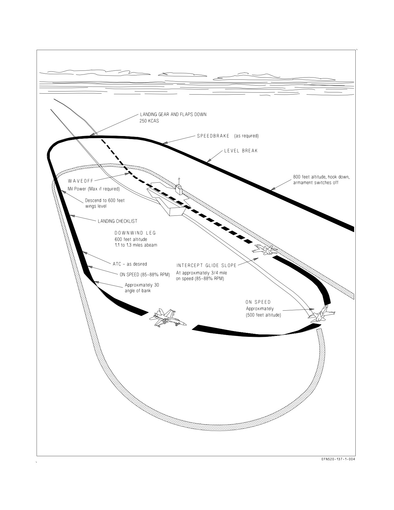
Enter the carrier landing pattern at 800 feet AGL (figure 8-2) with the hook down. Make a level
break from a course parallel to the Base Recovery Course (BRC), close aboard to the starboard side of
the ship. Below 250 KCAS lower the gear and flaps. The speedbrake function automatically retracts
when the FLAP switch is moved to HALF or FULL. Descend to 600 feet AGL when established
III-8-12
ORIGINAL
A1-F18EA-NFM-000
Figure 8-2. Carrier Landing Pattern
III-8-13
ORIGINAL
A1-F18EA-NFM-000
downwind and prior to the 180° position. Complete the landing checklist and crosscheck AOA and
airspeed (136 KCAS at 44,000 lb GW minus 1.5 KCAS for each 1,000 lb decrease in GW).
NOTE
Flaps HALF or FULL may be used for landing provided the minimum
wind-over-deck (WOD) requirements of the Aircraft Recovery Bulletin
(ARB) are met. As WOD increases above 30 kt, handling qualities in
flaps HALF are slightly improved over flaps FULL and are
recommended to avoid ″settle at the ramp″ situations.
To assist in achieving the desired abeam distance of 1.1 to 1.3 nm: select the 10 nm scale on the HSI
display, select ship’s TCN, and adjust the course line to the BRC. On downwind fly to place the wingtip
of the HSI airplane symbol on the course line. Ensure the ground track pointer is on the exact
reciprocal of the BRC. Select ILS if desired and available.
With 25-30 kt winds over deck begin the 180° turn to the final approach when approximately abeam
the LSO platform or when the ″white″ of the round down becomes visible. Use an instrument scan from
the 180 to the 90. Fly the pattern as described in the VFR Pattern and Approach section of Chapter
7. Adjust the 90 altitude up slightly to account for the height of the ship’s deck, usually 500 feet AGL
versus 450 feet AGL. Target 360 feet crossing the wake. The rate of descent required to maintain
glideslope may be slightly less than on FCLP approaches due to wind over deck. Expect slightly higher
throttle settings. When the meatball is acquired, transmit “SIDE NUMBER, RHINO, BALL, (fuel
state in thousands of pounds to the nearest 100 pound), AUTO” (if using ATC for approach) e.g. ″206,
RHINO, BALL, 7.5, Auto″. If unable to see any or all of the following: the meatball, datums, or
centerline, transmit
(SIDE NUMBER, CLARA/CLARA datums/CLARA lineup.″
(e.g.
″206,
CLARA″). See figure 8-3 for a typical Carrier Controlled Approach.
8.2.8.1
ATC Approach Mode Technique. Refer to the ATC Approaches section of Chapter 7 for
basics on ATC operations. ATC stick-to-throttle gains are designed to allow correction of settles or
updrafts with small, rapid stick movements. Close-in corrections are very critical. If a large attitude
correction for a high-in-close situation develops, the recommended procedure is to stop ball motion,
making no attempt to recenter the ball. A low-in-close condition is difficult to correct with ATC and
may result in an over-the-top bolter. It may be necessary to downgrade from ATC and fly manually to
safely recover from a low-in-close condition. The force required to manually disengage ATC is
significant and may prevent salvaging the pass. Large deviations from glideslope may be difficult to
correct with ATC. Typically, ATC should be disengaged if more than one ball from center (or upon
LSO direction) and the approach continued manually.
8.2.8.2
Glideslope. The technique for maintaining glideslope is basically the same as FCLP except
that more power may be required. Maintaining centerline will most likely require more line-up
corrections due to the angled deck. With rough seas and a pitching deck, some erratic ball movement
may be encountered. If this is the case, listen to LSO calls and attempt to average out ball movement
to maintain a safe, controlled approach.
8.2.8.3
Waveoff. When the waveoff signal is received, select MIL (MAX if required) and maintain
on-speed AOA with the E-bracket until rate of descent is arrested and 10° pitch attitude is captured
for climb to pattern altitude. Best rate of climb occurs at on-speed AOA regardless of loading or
configuration. This requires slight back stick pressure as the aircraft accelerates. If ATC is engaged,
III-8-14
ORIGINAL
A1-F18EA-NFM-000
immediately disengage ATC or apply enough force to override ATC while advancing the throttles to
MIL or MAX. Do not over-rotate.
An in-close or late waveoff, coupled with an over-rotation can lead to an
in-flight engagement, which can severely damage the aircraft and/or
arresting gear.
8.3 ACL MODE 1 AND 1A APPROACHES
A typical Mode 1 and 1A approach is shown in figure 8-4. The Mode 1/1A approach does not require
ATC, but ATC should normally be used. The following procedure is typical for a Mode 1 (1A) approach
from marshal to touchdown (or 0.5 mile).
1. Request a Mode 1 or Mode 1A approach from Marshal.
2. HSI format - SELECT (box) ACL
When the ACL option is boxed, the LINK 4 format automatically appears on the LDDI, and the
ACL mode automatically starts its self test. At this time, the ILS, data link, and radar beacon are
automatically turned on (if not previously on), and IBIT is run on the data link and radar beacon
systems. Also, the uplinked universal test message is monitored for valid receipt.
3. Onboard ACL Capability - CHECK
a. LINK 4 format - CHECK FOR ACL 1
Mode 1/1A capability is not available if ACL 1 is not displayed.
b. BIT page, NAV Sublevel - Verify AUG GO/PBIT GO
An augmentor degrade does not inhibit ACL coupling. A degraded
augmenter may lead to a significant lineup error, most often tending
right-of-centerline.
4. Report departing marshal - ″SIDE NUMBER, COMMENCING″
5. Normal CCA - PERFORM
Descend at 250 KCAS and 4,000 fpm to 5,000 feet, (platform) then reduce rate of descent to 2,000
fpm. When selected, ILS steering is automatically displayed on the HUD once valid signals are
received and must be manually deselected, if the symbology is not desired.
a. At 5,000 ft MSL, report - ″SIDE NUMBER, PLATFORM″
b. Continue descent to 1,200 ft MSL.
c. At 10 nm, report - ″SIDE NUMBER, 10 MILES″
III-8-15
ORIGINAL
A1-F18EA-NFM-000
6. LDG GEAR handle - DN (at 10 nm but NLT 8 nm)
7. FLAP switch - FULL or HALF
NOTE
• Flaps may be switched between FULL and HALF while remaining
coupled outside of one nautical mile from touchdown.
• When coupled, changing flap position inside one nautical mile from
touchdown is prohibited.
8. Landing checklist - COMPLETE
a. Check the LDDI for ID LT indication.
9. Slow to approach speed at 6 nm.
10. ATC - ENGAGE
11. RALT hold mode - ENGAGE (if desired)
ACL acquisition occurs at approximately 3.5 to 8 nm and is indicated by ACL RDY on the LINK 4
format and the data link steering (TADPOLE) on the HUD. It is desired but not required, to have
ACL coupled at least 30 seconds before tipover. T/C is replaced by MODE 1 on the LINK 4 format.
After ACL Acquisition -
12. Report needle position - e.g., ″UP AND ON″ or ″UP AND RIGHT″.
For Mode 1, when directed -
13. CPL option - SELECT on UFCD
If T/C is engaged, press CPL once to uncouple T/C then press CPL again to couple ACL. When
the aircraft is not coupled, ACL RDY is displayed on the HUD. ACL couple is indicated by CMD
CNT and MODE 1 on the LINK 4 format and CPLD P/R on the UFCD and HUD. At this time,
the uplinked command displays of heading, airspeed, altitude, and rate of descent are removed
from the LINK 4 format and the HUD.
14. When coupled, report - ″COUPLED″
15. When aircraft responds to automatic commands, report - ″COMMAND CONTROL″
For Mode 1A Approach -
16. Downgrade to Mode 2 at 0.5 mile by
a. Paddle switch - PRESS
b. ATC button - DISENGAGE (if desired)
III-8-16
ORIGINAL
A1-F18EA-NFM-000
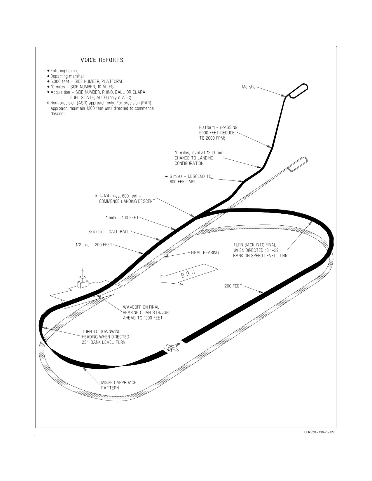
Figure 8-3. Carrier Controlled Approach
III-8-17
ORIGINAL
A1-F18EA-NFM-000
17. Report - ″SIDE NUMBER, RHINO, BALL or CLARA, FUEL STATE, AUTO″ (if ATC
engaged).
For Mode 1 Approach -
11. Report - ″SIDE NUMBER, RHINO, BALL or CLARA, FUEL STATE, COUPLED″.
12. At approximately 12.5 seconds before touchdown, the uplinked 10 SEC cue is displayed on the
LINK 4 format and the HUD.
13. After touchdown, ACL and ATC should be automatically disengaged.
NOTE
After Mode 1 or 1A downgrade or touch-and-go, actuate the paddle
switch to ensure complete autopilot disengagement.
8.4 ACL MODE 2 APPROACH
A typical ACL Mode 2 approach is shown in figure 8-5. For a Mode 2 approach, the HUD data link
steering is used to fly a manual approach.
1.
HSI format - SELECT (box) ACL
When the ACL option is boxed, the LINK 4 format automatically appears on the LDDI, and the
ACL mode automatically starts its self test. At this time, the ILS, data link, and radar beacon are
automatically turned on (if not previously on), and IBIT is run on the data link and radar beacon
systems. Also, the uplinked universal test message is monitored for valid receipt.
2.
LINK 4 format - CHECK FOR ACL 1 or ACL 2
Mode 2 capability is not available if ACL 1 or ACL 2 is not displayed.
3.
Report departing marshal - ″SIDE NUMBER, COMMENCING″
4.
Normal CCA - PERFORM
Descend at 250 KCAS and 4,000 fpm to 5,000 feet, (platform) then reduce rate of descent to 2,000
fpm. When selected, ILS steering is automatically displayed on the HUD once valid signals are
received and must be manually deselected, if the symbology is not desired.
a. At 5,000 ft MSL, report - ″SIDE NUMBER, PLATFORM″
b. Continue descent to 1,200 ft MSL.
c. At 10 nm, report - ″SIDE NUMBER, 10 MILES″
5.
LDG GEAR handle - DN (at 10 nm but NLT 8 nm)
6.
FLAP switch - FULL (HALF if required)
7.
Landing checklist - COMPLETE
III-8-18
ORIGINAL
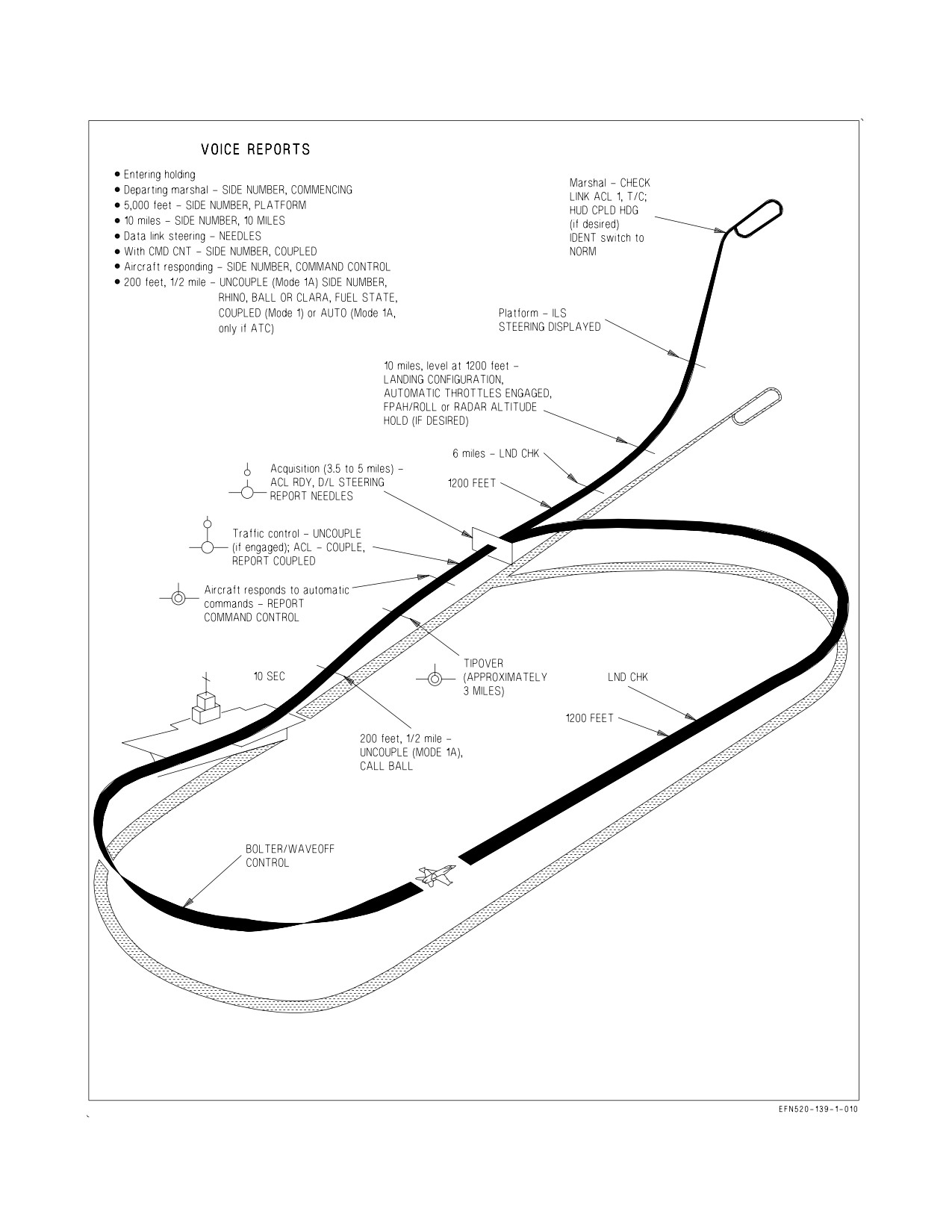
A1-F18EA-NFM-000
Figure 8-4. ACL Mode 1 and 1A Approaches
III-8-19
ORIGINAL
A1-F18EA-NFM-000
a. Check the LDDI for ID LT indication.
8. Slow to approach speed at 6 nm.
9. ATC - ENGAGE (if desired)
10. RALT hold mode - ENGAGE (if desired)
ACL acquisition occurs at approximately 3.5 to 8 nm and is indicated by ACL RDY on the LINK 4
format and the data link steering (TADPOLE) on the HUD.
After ACL Acquisition -
11. Report needle position - e.g., ″UP AND ON″ or ″UP AND RIGHT″.
12. Report - ″SIDE NUMBER, RHINO, BALL or CLARA, FUEL STATE, AUTO″ (if ATC
engaged).
8.5 ARRESTED LANDING AND EXIT FROM THE LANDING AREA
1. Fly an on-speed, on centerline, centered-ball approach all the way to touchdown.
At touchdown -
2. Throttles - MIL
To reduce aircraft and arresting gear loads and required recovery wind-
over-deck, selection of MAX power at touchdown shall not be performed
except in an emergency.
When forward motion ceases -
3. Throttles - IDLE and allow the aircraft to roll aft.
When directed -
4. Brakes - APPLY
5. HOOK handle - UP
If the wire does not clear the hook, the taxi director will signal to lower the hook for aircraft
pullback.
6. FLAP switch - AUTO
7. WINGFOLD switch - HOLD or FOLD (HOLD if wingtip missile dearming required)
8. NWS button - ENGAGE NWS HI
III-8-20
ORIGINAL
A1-F18EA-NFM-000
When the come ahead signal is received, add power, release brakes, and exit the landing area
cautiously and expeditiously. Taxi the aircraft as directed. Do not use excessive power. If one or both
brakes fail, utilize the emergency brakes; advise the tower; and drop the arresting hook.
Once spotted, keep the engines running until the taxi director signals engine shutdown and the
aircraft is properly chocked and chained.
8.6 SECTION CCA
A section CCA may be necessary when a failure occurs which affects navigation aids, communica-
tions equipment, or other aircraft systems. Normally, the aircraft experiencing the difficulty flies the
parade position on the starboard side during the approach. When the meatball is sighted, but no lower
than 300 feet AGL, the section leader breaks away from the wingman in a climbing left turn. The
section leader should climb to 1,200 feet AGL, or below an overcast, in the bolter configuration, and
position himself at the wingman’s 11:00 o’clock position. If the wingman bolters or waves-off, he should
rendezvous in the bolter configuration on the section leader. If a wave-off is required prior to flight
break-up, the flight leader executes a climbing right turn to 1,200 feet AGL and follows the directions
of CATCC. Necessary lighting signals between aircraft are contained in Chapter 26.
NOTE
A section penetration should not be made to the ship with less than
non-precision minimums.
8.7 NIGHT OPERATIONS
8.7.1 General. Night carrier operations have a much slower tempo than day operations and it is the
pilot’s responsibility to maintain this tempo. Standard daytime hand signals from deck crew to pilot
are executed with light wands. The procedures outlined here are different from, or in addition to,
normal day carrier operations.
8.7.2 Preflight. Conduct the exterior preflight using a white-lensed flashlight. Ensure that the
exterior lights are properly set for night launch and the external lights master switch is OFF before
engine start. Ensure that instrument and console light knobs are on. This will reduce the brilliance of
the warning and advisory lights when the generators come online.
8.7.3 Before Taxi. Adjust cockpit lighting as desired and perform Before Taxi Checks.
8.7.4 Taxi. Slow and careful handling by taxi directors and pilots is mandatory. If any doubt exists
as to taxi director signals, stop the aircraft. At night it is very difficult to determine speed and motion
over the deck, so the pilot must rely on the taxi director signals, following them closely.
8.7.5 Catapult Hook-Up. Maneuvering the aircraft for catapult hook-up at night is identical to that
used in day operations; however, it is difficult to determine speed or degree of motion over the deck.
If the taxi director is obscured by steam from the catapult, stop the aircraft.
8.7.6 Catapult Launch. At night, catapult procedures are the same as daytime, except signals are
provided by lights instead of hand signals. The exterior lights are utilized to signal that the pilot is
ready for launch. After the control wipeout, select the ADI for display on a DDI or the UFCD in case
the HUD should be lost during or immediately after launch. When ready for launch, place external
lights master switch to ON.
III-8-21
ORIGINAL
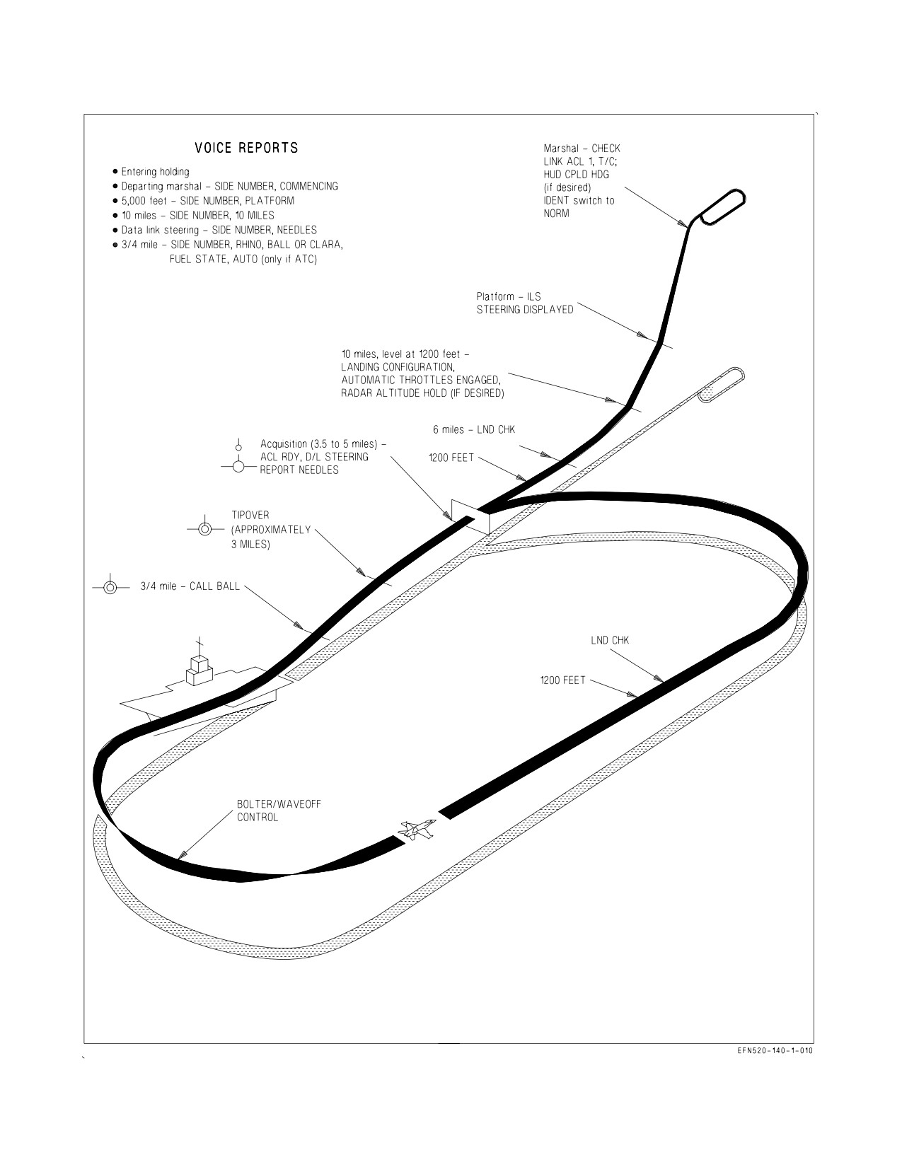
A1-F18EA-NFM-000
Figure 8-5. ACL Mode 2 Approach
III-8-22
ORIGINAL
A1-F18EA-NFM-000
All exterior lights (position, formation, and strobes) should be on. If instrument meteorological
conditions are expected shortly after launch, the strobes may be left off at the discretion of the pilot.
After launch, monitor rotation of the aircraft to 12° AOA, crosschecking all instruments to ensure
a positive rate of climb. When comfortably climbing, retract the landing gear and flaps and proceed on
the departure IAW CV NATOPS.
8.7.7 Catapult Suspend. To stop the launch while in tension on the catapult, do not turn on the
exterior lights and transmit “SUSPEND, SUSPEND”. Maintain MIL/MAX power until the catapult
officer walks in front of the wing and gives the throttle-back signal. If the external lights master switch
has been placed on prior to ascertaining that the aircraft is down, transmit “SUSPEND, SUSPEND”
and turn off the exterior lights and leave the throttles at MIL until signaled to reduce power.
8.7.8 Night Landings. Night and instrument recoveries will normally be made using case III
procedures IAW CV NATOPS. Prior to departing marshal, change the IDENT switch on the exterior
lights panel to the NORM position. Make sure the strobe lights are flashing a 3 flash, pause, repeat
pattern.
8.7.9 AN/APG-79 AESA Considerations. Aircrew operating AN/APG-79 AESA equipped aircraft
shall be aware that directing AN/APG-79 AESA transmissions toward the ship while on approach may
cause strong electromagnetic interference (EMI) affecting the safety of aircraft on approach. Unless
specifically authorized for operational necessity or required for safety of flight, aircrew shall cease
AN/APG-79 AESA radar transmissions whenever operating within 10 nm of the ship while on
approach during IMC/Case III conditions. Reference Chapter 4.4 for AN/APG-79 AESA radar
limitations.
8.7.10 Arrestment and Exit From the Landing Area. During the approach, all exterior lights should
be on with the exception of the landing/taxi light. Following arrestment, immediately turn the external
lights master switch off. Taxi clear of the landing area following taxi director signals. If brakes are lost,
signal by lowering the hook, turning on exterior lights, and transmitting on land/launch frequency.
III-8-23
(Reverse Blank)
ORIGINAL W/IC 33
A1-F18EA-NFM-000
CHAPTER 9
Special Procedures
9.1 FORMATION FLIGHT
9.1.1 Formation Taxi/Takeoff. During section taxi, ensure adequate clearance between flight lead’s
stabilator and wingman’s wing/missile rail is maintained. The leader will take position on the
downwind side of the runway with other aircraft in tactical order, maintaining normal parade bearing.
See figure 9-1. For three aircraft formations, line up with the lead on the downwind side, number 2 on
the centerline, and number 3 on the upwind side. Wingtip/launch rail overlap should not be required
but is permitted if necessary. For four plane formations, line up with the lead’s section on the
downwind half of the runway and other section on the upwind half. When Before Takeoff checks are
completed and the flight is in position, each pilot looks over the next aircraft to ensure the speed brake
is retracted (spoilers down), the flaps are set for takeoff, all panels are closed, no fluids are leaking,
safety pins are removed, rudders are toed-in, nosewheel is straight, and the launch bar is up. Beginning
with the last aircraft in the flight, a “thumb up” is passed toward the lead to indicate “ready for
takeoff”.
9.1.1.1
Section Takeoff. For section takeoff, all aspects of the takeoff must be prebriefed by the
flight leader, to include flap settings; use of nosewheel steering; power changes; power settings; and
signals for actuation of landing gear, flaps, and afterburner. Engines are run up to approximately 80%,
instruments checked, and nosewheel steering low gain ensured. On signal from the leader, brakes are
released and throttles are advanced to military power minus 2% rpm. If afterburner is desired, the
leader may go into mid range burner immediately without stopping at military power. Normal takeoff
techniques should be used by the leader, with the wingman striving to match the lead aircraft attitude
as well as maintain a position in parade bearing with wingtip separation. The gear and flaps are
retracted on signal. Turns into the wingman shall not be made at altitudes less than 500 feet above
ground level.
9.1.2 Aborted Takeoff. In the event of an aborted takeoff, the aircraft aborting must immediately
notify the other aircraft. The aircraft not aborting should add max power and accelerate ahead and out
of the way of the aborting aircraft. This allows the aborting aircraft to steer to the center of the runway
and engage the arresting gear, if required.
9.1.3 Parade. The parade position is established by superimposing the front of the wingtip missile
rail over the pilot’s headbox. Superimposing the two establishes a bearing line and step down. Proper
wingtip clearance is set by reference to the exhaust nozzles. When the left and right nozzles are aligned
so that there is no detectable curve to the nozzles, the reference line is correct. The intersection of the
reference line with the bearing line is the proper parade position. See figure 9-2.
Parade turns are either standard (VFR) or instrument turns. During day VFR conditions, turns
away from the wingman are standard turns. To execute, when lead turns away, the wingmen roll the
aircraft about its own axis and increase power slightly to maintain rate of turn with the leader. Lateral
separation is maintained by increasing g. Proper step down is maintained by keeping the lead’s fuselage
on the horizon.
Turns into the wingmen and all IFR or night turns in a parade formation are instrument turns.
During instrument turns maintain a parade position relative to the lead throughout the turn.
III-9-1
ORIGINAL
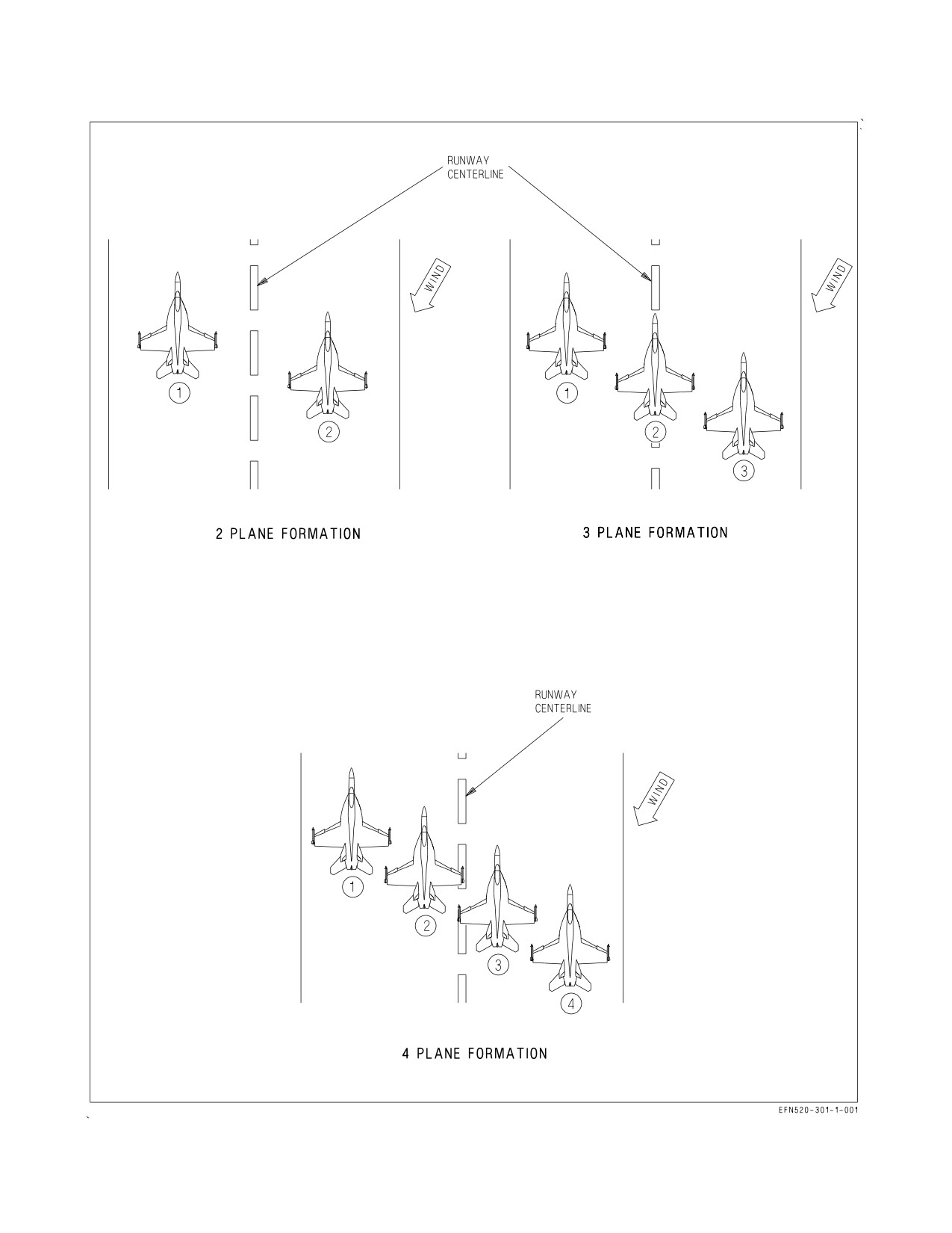
A1-F18EA-NFM-000
Figure 9-1. Formation Takeoff Runway Alignments
III-9-2
ORIGINAL
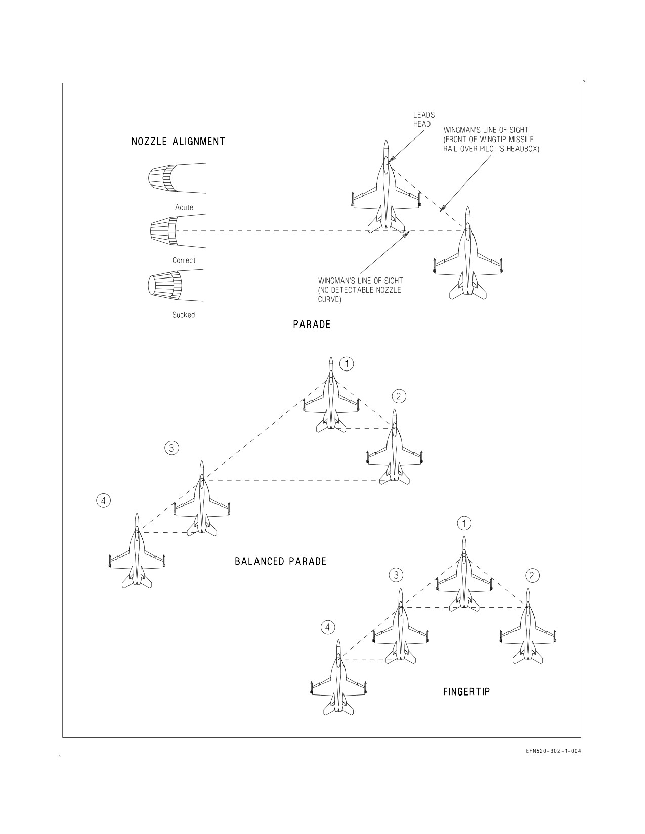
A1-F18EA-NFM-000
Figure 9-2. Formations (Sheet 1 of 2)
III-9-3
ORIGINAL
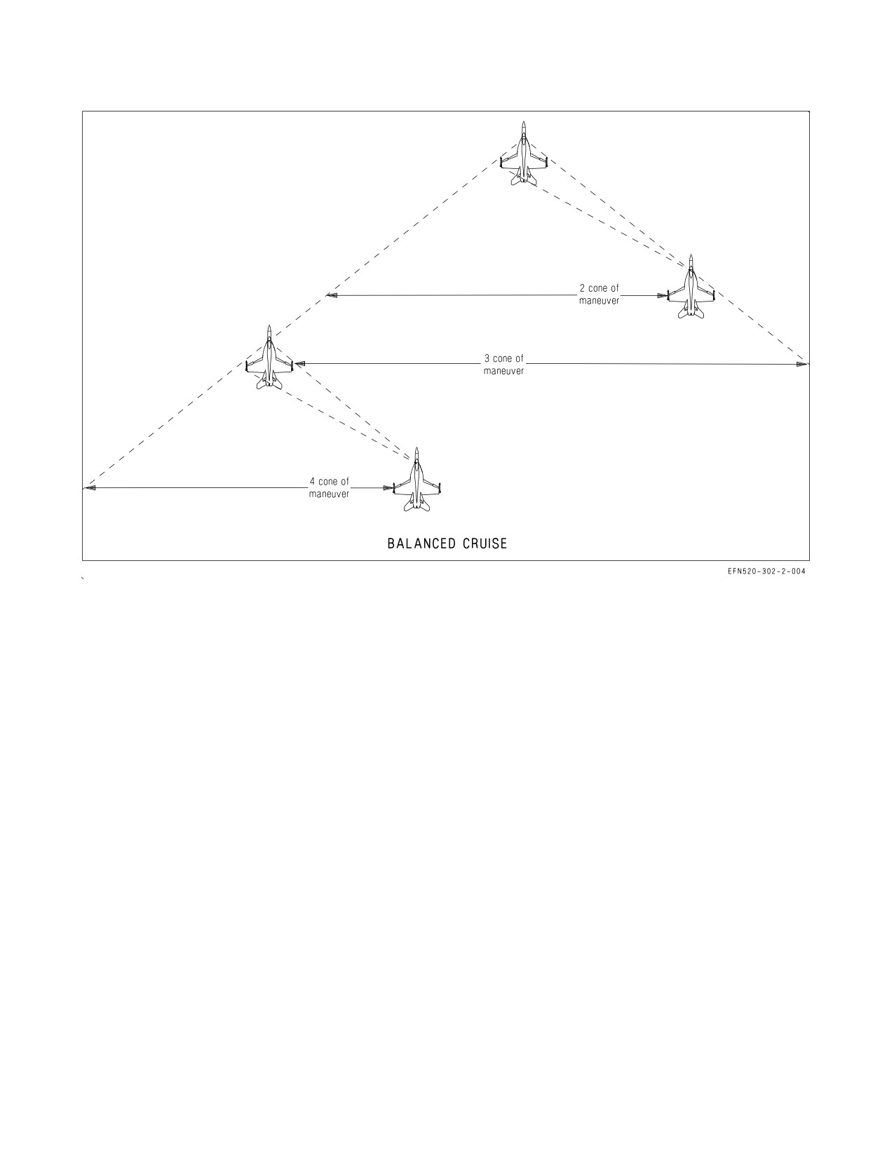
A1-F18EA-NFM-000
Figure 9-2. Formations (Sheet 2 of 2)
After initially joining up in echelon, three and four plane formations normally use balanced parade
formation. In balanced parade number 3 steps out until the exhaust nozzles on number 2 are flush. This
leaves enough space between number 3 and lead for number 2 to cross under into echelon.
When it is necessary to enter IFR conditions with a three or four plane formation, the lead directs
the flight to assume fingertip formation. In this formation number 3 moves up into close parade on the
lead. All turns are instrument turns.
9.1.4 Balanced Cruise Formation. The balanced cruise position is a looser formation which allows
the wingmen more time for visual lookout. Balanced cruise provides the wingmen with a cone of
maneuver behind the leader which allows the wingman to make turns by pulling inside the leader, and
requires little throttle change.
The balanced cruise position is defined by the wingman aligning his headbox with the front of lead’s
wingtip missile rail and headbox, and lead’s arresting hook fairing with the opposite wing formation
light. The wingmen are free to maneuver within the cone established by that bearing line on either
wing. In a division formation, number 3 should fly the bearing line but always leave adequate room for
number 2 and lead. Number 4 flies balanced cruise about number 3.
9.1.5 Section Approaches/Landing. The aircraft is comfortable to fly in formation, even at the low
airspeeds associated with an approach and landing. The rapid power response enhances position
keeping ability. The formation strip lighting provides a ready visual reference at night and the dual
radios generally ensure that intra-flight comm is available.
III-9-4
ORIGINAL
A1-F18EA-NFM-000
During section approaches all turns are “instrument” turns about the leader. When a penetration is
commenced the leader retards power to 75% rpm and descends at 250 KIAS. If a greater descent rate
is required the speed brake may be used. Approximately 5 miles from the final approach fix or GCA
pickup the lead gives the signal for landing gear.
9.1.5.1
Section Landing. If a section landing is to be made, lead continues to maintain ON-SPEED
for the heaviest aircraft and flies a centered ball pass to touchdown on the center of one side of the
runway. Wingman flies the normal parade position, taking care not to be stepped up.
When “in-close”, wingman adds the runway to his scan and takes a small cut away from the lead to
land on the center of the opposite side of the runway while maintaining parade bearing. Use care to
ensure that drift away from the lead does not become excessive for the runway width. Remember,
flying a pure parade position allows 4 feet of wingtip clearance.
The wingman touches down first and decelerates on that half of the runway as an individual. Do not
attempt to brake in section. If lead must cross the wingman’s nose to clear the duty, the wingman calls
“clear” on comm 2 when at taxi speed and with at least 800 feet between aircraft. The lead stops after
clearing the runway and waits for the wingman to join for section taxi.
9.2 AIR REFUELING (RECEIVER)
Air refueling shall be conducted in accordance with NATO publication ATP-56, Air-to-Air Refueling
Procedures.
NOTE
The KC-10, KC-130, KC-135 tankers, F/A-18E/F and S-3 aircraft with
a
31-301
(A/A42R-1) buddy store are authorized tankers for air
refueling. Maximum refueling pressure is 55 psi.
9.2.1 Air Refueling Checklist. The air refueling checklist should be complete prior to plug-in.
1. RADAR - STBY/SILENT/EMCOM (″nose cold″)
2. MASTER ARM switch - SAFE (″switches safe″)
3. ALE-50 transmit power - OFF (if decoy deployed)
4. INTR WING switch - NORM (or as required)
5. EXT TANK switch(es) - AS DESIRED
If feed tank fuel level is critical, selecting STOP ensures the fastest transfer of fuel to the feed
tanks.
NOTE
For ARS configured aircraft: If fueling of the ARS is not desired
during aerial refueling, as the receiver, CTR ORIDE must be selected
since CTR STOP will not prevent fuel from entering the ARS.
Selecting CTR ORIDE will pressurize all external fuel tanks and
significantly reduce refueling rate.
III-9-5
ORIGINAL
A1-F18EA-NFM-000
6. PROBE switch - EXTEND
7. Visor - DOWN (recommended)
For night air refueling -
8. Exterior lights - SET FOR REFUELING
9. Tanker lights - REQUEST AS DESIRED
9.2.2 Refueling Technique. The following procedures, as applied to tanker operations, refer to single
drogue refueling from the F/A-18E/F and the aerial refueling store. All other tanking evolutions are
dependent on the type of tanker being utilized. Refer to Chapter 26, Visual Communications, for
proper hand signals during air refueling operations.
A sharp lookout doctrine must be maintained due to the precise flying imposed on both the tanker
and receiver pilots. Other aircraft in the formation may assist the tanker in maintaining a sharp
lookout. Refueling altitudes and airspeeds are dictated by receiver and/or tanker characteristics
balanced with operational needs. This typically covers a practical envelope from the surface to 40,000
feet and 180 to 300 KCAS (while engaged), depending on the buddy store part number. (See figure
4-13).
9.2.2.1
Approach. When cleared to commence an approach and the refueling checklist is complete,
assume a ready position 10 to 15 feet in trail of the drogue with the refueling probe in line both
horizontally and vertically. Once in a stabilized position, trim the aircraft and make sure the tanker
ready light (amber) is on. Referencing the probe and drogue for alignment, increase power to establish
a 3 to 5 knot closure rate.
• If the tanker ready light is not on, do not engage drogue until signaled
by tanker aircraft as hose-reel response may be inoperative, causing
damage to tanker and receiver aircraft.
• Avoid damage to the right AOA probe by contact with the basket as a
4 channel AOA failure may result.
• An excessive closure rate may cause a violent hose whip following
contact and/or increase the danger of structural damage to the aircraft
in the event of misalignment.
NOTE
An insufficient closure rate results in the pilot fencing with the drogue
as it oscillates in close proximity to the aircraft nose.
Make small corrections during the approach phase using the rudder pedals for lateral misalignment
and longitudinal stick for vertical misalignment. Avoid lateral stick inputs as they cause both vertical
and lateral probe displacement. During the final phase of the approach, the drogue has a tendency to
move up and to the right as it passes the nose of the receiver aircraft due to the aircraft-to-drogue air
stream interaction.
III-9-6
ORIGINAL
A1-F18EA-NFM-000
9.2.2.2
Missed Approach. A missed approach is executed by reducing power and backing to the rear
with a 3 to 5 knot opening rate. Execute a missed approach if:
1. The receiver probe and the drogue basket cannot be properly aligned during the final phase of the
approach.
2. The receiver probe passes forward of the drogue basket.
3. The receiver probe impinges on the rim of the drogue basket.
4. Any unsafe condition develops.
Analyze alignment problems prior to commencing another approach.
9.2.2.3
Contact. When the receiver probe engages the basket, it seats itself into the reception
coupling and a slight ripple is evident in the refueling hose. The drogue and hose must be pushed
forward 5 feet by the receiver aircraft before fuel transfer can be started. This position is evident by
the tanker ready light (amber) going out and the (green) fuel transfer light (green) coming on. During
refueling, maintain a position directly behind and slightly below tanker aircraft.
NOTE
If streaming fuel is observed around the refueling probe, the probe is
not properly seated in the drogue. Disengage, stabilize in the ready
position, and then reengage the drogue.
9.2.2.4
Disengagement. The receiver aircraft disengages by reducing power in order to open from
the tanker at 3 to 5 knots. Back straight away and down, following the flight path of the tanker. The
receiver probe separates from the reception coupling when the hose reaches full extension. When clear
of the drogue, place the PROBE switch in the RETRACT position. Make sure that the PROBE UNLK
caution display is out before resuming normal flight operations.
• Disengagement must be made straight back, parallel to the tanker
flight path, and descending along the natural trail angle of the hose to
prevent damage to the tanker and/or refueling aircraft.
• When installed on the F/A-18 E/F tanker, the ARS hose/drogue/
coupling exhibits a strong tendency to re-center in its natural trail
position. Off-center disconnects may result in drogue contact and
damage to the aircraft. Avoid off-center disconnects and maintain a
constant separation rate until clear.
9.2.2.5
KC-10 Refueling Operations. The KC-10 tanker is equipped with a centerline hose reel
system and/or two Wing Aerial Refueling Pods (WARP). Maximum in-flight refueling airspeed and
altitude for the F/A-18E/F when refueling from the KC-10 is 275 KCAS and 25,000 feet with an
optimum airspeed of 220 KCAS. At airspeeds above 250 KCAS, tanker induced light turbulence causes
III-9-7
ORIGINAL
A1-F18EA-NFM-000
random drogue movement of 2 to 3 feet while 1 foot of movement will be encountered at airspeeds less
than 250 KCAS. The recommended closure rate is 2 to 3 knots.
When joining a flight of receiver aircraft, do not close astern of the KC-10
within 1 to 3 miles from co-altitude to 500 feet below. Loss of aircraft
control can occur if wake turbulence is encountered.
Excessive closure rates may exceed the capabilities of the take-up reel. If
this should happen, a sine wave develops in the hose. Immediate
disengagement is required to prevent damage to the aircraft.
9.2.2.6
KC-135 Refueling Operations. The KC-135 may be configured with a Multi-Point Refueling
System (MPRS) and/or a Boom to Drogue Adapter (BDA) kit.
9.2.2.6.1
KC-135 BDA Refueling. The KC-135 hose has a fixed length of 9 feet attached by a
swiveling coupling to the end of a telescoping boom. The hose terminates in a hard, non-collapsible
drogue and has no reel retraction capability. The following refueling parameters are recommended:
• Airspeed of 200 to 275 KCAS or Mach 0.8 (whichever is less).
• Closure rate of 2 knots or less.
Aerial refueling from the KC-135 is fundamentally different from the standard Navy hose-drogue
systems. After assuming a standard ready position, add power to create a closure rate of 2 knots or less.
Due to the short length of hose and the weight of the drogue, the aircraft-to-drogue air stream
interaction is minimized.
Excessive closure rates (greater than 2 knots) may result in damage to the
aircraft or the refueling drogue.
Once contact has been made, the drogue must be pushed in approximately 4 feet and held in that
position within ±2 feet fore and aft for fuel to flow (the hose forms a U-shape when in the correct
position). If the F/A-18E/F is positioned too far aft with the hose near the trail position, slight aft or
radial movement results in disconnect. The potentially more hazardous situation occurs when the
drogue is pushed too far forward, such that the hose could be looped around the drogue on the probe.
III-9-8
ORIGINAL
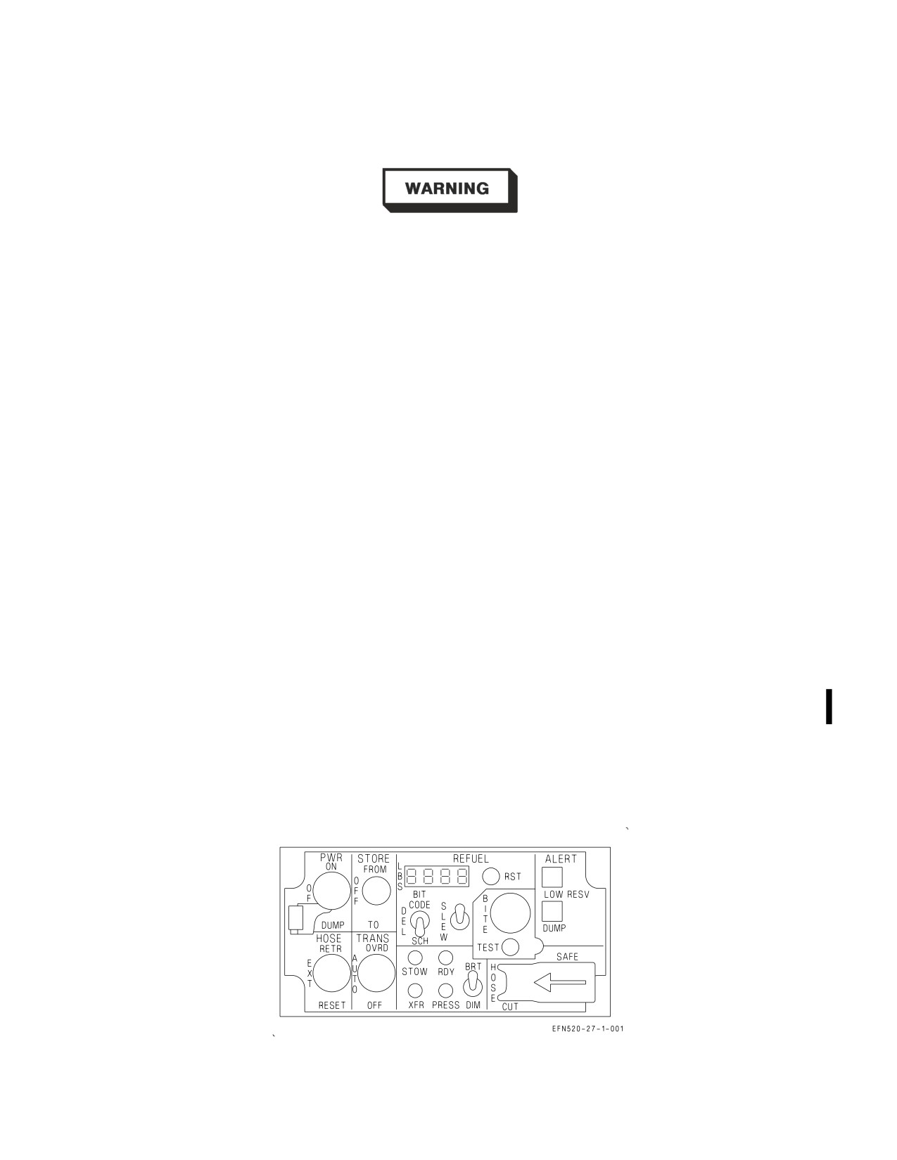
A1-F18EA-NFM-000
When disengaging, align the drogue with the boom and back straight away with reference to the
boom.
Off-center disconnects can result in damage to the refueling probe or
nozzle because of the excessive sideloads generated by the KC-135
boom-drogue adapter.
9.2.2.6.2
KC-135 MPRS Refueling. The KC-135 MPRS incorporates the use of wing tip mounted
aerial refueling pods to support receivers designed for hose/drogue refueling operations. The refueling
hose is slightly shorter than the KC-130 and located near the wing tips. The extreme outboard wing
location subjects the hose and drogue to wing tip flowfield disturbances at higher refueling speeds.
• Maximum recommended refueling speed 285 KCAS (up to 300 KCAS/0.86 IMN allowed)
• Optimum refueling airspeeds 260 - 285 KCAS.
While flying at the approach position (20 ft aft of the drogue), small lateral trim inputs may be
required to counter a tendency to roll toward the tanker. Deviations inboard and outboard may require
additional lateral stick inputs. Deviations of more than 10 feet high can result in a strong sideslip (on
right tanker wing, full left ball). Light buffet is a good indication to reposition down with respect to the
tanker.
Maintaining a slow controlled constant closure rate (less than 5 knots) will result in the best
engagement results. Tanking at 300 knots is demanding due to increased bow wave effects and high
drogue position.
9.3 AIR REFUELING (TANKER)
Air refueling shall be conducted in accordance with NATO publication ATP-56, Air-To-Air
Refueling Procedures.
9.3.1 Air Refueling Store (ARS). The ARS is a missionized component for in-flight refueling. The
ARS control panel (figure 9-3) provides power, fuel transfer operation, fuel status indicators, BIT
status, and normal hose extension/retraction, and hose jettison capability.
Figure 9-3. ARS Control Panel
III-9-9
ORIGINAL
A1-F18EA-NFM-000
9.3.1.1
Power Switch (PWR). The PWR switch provides electrical and hydraulic power to the store.
NOTE
For the -4/-5 ARS stores, once powered on (220 KCAS min), airspeed
may be reduced to as slow as 180 KCAS to transfer fuel below 5,000 ft
MSL. Attempts to power on below 220 KCAS will be unsuccessful and
accelerating to 220 KCAS will not recover the RAT. Store power must
be turned off and airspeed increased to 220 KCAS or greater before
re-applying power.
ON Electrical power is routed in the store and the ram air turbine (RAT) unfeathers, which
provides hydraulic power.
OFF Feathers the RAT and removes electrical and hydraulic power.
DUMP Disabled and safety guarded.
NOTE
If the hose is extended, the PWR switch is bypassed (cannot be turned
OFF).
9.3.1.2
STORE Switch. The STORE switch controls fuel transfer between the store and tanker (own
aircraft).
FROM Pressurizes the store to transfer fuel from store to own aircraft.
OFF Depressurizes store.
TO
Replenish ARS with own aircraft fuel.
9.3.1.3
REFUEL Display. The four digit display indicates fuel (in pounds) delivered or scheduled, a
three digit BIT code - when commanded, or a 0E when a serious malfunction occurs. The display
initially powers up with 2,500 lb scheduled.
9.3.1.4
Refuel RST Button. A momentary pushbutton that returns LBS scheduled or delivered to
original settings. Pounds scheduled returns to 2,500 pounds or previously scheduled quantity. Pounds
delivered returns to zero.
9.3.1.5
Refuel Data Display Switch. The refuel data display switch is a three position toggle switch
which is spring-loaded to the delivery (DEL) position. The switch can be toggled to the BIT CODE or
scheduled (SCH) positions.
BIT
Three digit number indicates a malfunction code.
CODE
DEL Pounds of fuel being transferred (25 lb increments).
III-9-10
ORIGINAL
A1-F18EA-NFM-000
SCH Pounds of fuel scheduled to be transferred. When scheduled point is reached, automatic
transfer is terminated. 2,500 lb automatically scheduled at power up.
9.3.1.6
Refuel SLEW Switch. The SLEW switch is a three position toggle switch which is spring-
loaded to the center position. If the refuel data display switch is in the SCH position, moving the switch
up increases pounds of fuel scheduled for transfer, and down decreases the fuel scheduled for transfer.
In SCH, the SLEW switch moves the selected indications as follows:
1.
0 to 100 lb, 75 lb/sec in 25 lb increments
2.
100 to 1,000 lb, 300 lb/sec in 100 lb increments
3.
>1,000 lb, 600 lb/sec in 200 lb increments
9.3.1.7
BITE Flag Indicator. The BITE flag indicator indicates failures in the control panel assembly.
9.3.1.8
ALERT Indicators. There are two ALERT lights on the right side of the ARS panel.
LOW A red warning light illuminates when the hydraulic reservoir level drops below ½ full
RESV and begins flashing when the reservoir level drops below ¼ full.
DUMP ARS DUMP is not functional.
9.3.1.9
HOSE CUT/SAFE Switch. The HOSE CUT/SAFE switch is a two position switch spring-
loaded to the SAFE position and held in SAFE by a spring-loaded guard. The switch is wired through
the WonW interlock to prevent accidental activation on the deck.
SAFE Normal position.
CUT Refueling hose is cut and crimped. ARS is deactivated hydraulically and electrically. In
flight, the switch must be held for several seconds.
9.3.1.10 Dimming (BRT/DIM) Switch. The BRT/DIM switch controls the intensity of the receiver
pilot advisory lights on the ARS tailcone and control panel displays. BRT is used for day operations,
and DIM is used for night operations.
9.3.1.11 Status Lights. There are four status lights on the ARS control panel.
STOW Green light comes on when hose is approximately one foot from complete stowage. If
hose/drogue is not fully stowed, the indication is through a MASTER CAUTION and
aural tone, and the ARS DROGUE caution appears on the DDI.
RDY Green light illuminates when the hose is fully deployed and automatic hose response is
established.
PRESS Green light illuminates when hydraulic pressure drops below 1,700 psi. Light goes out
when pressure exceeds 2,000 psi.
III-9-11
ORIGINAL
A1-F18EA-NFM-000
XFR Green light illuminates when a minimum of 20 gallons/min of fuel is being transferred
to the receiver.
9.3.1.12 TRANS Switch. The three position transfer switch is lever locked in the AUTO position and
controls fuel transfer to the receiver aircraft.
OVRD The ARS fuel pump is turned on regardless of hose position, fuel schedule, or fuel
remaining in the store. The OVRD position should only be used during emergency refu-
eling situations.
AUTO When connected to receiver aircraft, fuel flows when the following conditions are met:
• The hose is within the refueling range (approximately 5 to 20 feet of full trail),
• ARS (fuel is above 175 pounds) is not low on fuel; and,
• The scheduled amount of fuel is not exceeded.
OFF Turns the pump off regardless of hose position.
9.3.1.13 HOSE Switch. The three position switch controls the hose reel. The HOSE switch lever locks
in the RETR and EXT positions and is spring-loaded to EXT from the RESET position.
RETR The hose retracts or remains retracted.
EXT The hose extends or remains extended.
RESET Reset is used to establish a new reference pressure (after release to EXT) when air-
speed varies more than 10 KCAS from the last reference airspeed (either at extension
or at the time of the last RESET).
Do not select RESET when a receiver aircraft is plugged in. RESET
causes momentary loss of auto response and may damage receiver
aircraft.
Failure to reset hose reference pressure may result in hose auto retraction
if decelerating, or non-responsiveness if accelerating.
9.3.1.14 ARS DROGUE Caution. An ARS DROGUE caution on the DDI indicates that the ARS
PWR switch is OFF and the refueling drogue has not fully retracted.
9.3.2 ARS (Tanker) Procedures.
III-9-12
ORIGINAL