F18. FLIGHT MANUAL (2008) - page 21
A1-F18EA-NFM-000
4.1.4 Gross Weight and Lateral Weight Asymmetry Limitations. See figure 4-4 for gross weight and
lateral weight asymmetry limitations.
Condition
GW Limit (lb)
Asymmetry Limit1 (ft-lb)
Field Takeoff/In Flight
66,000
29,0002,3 (FLY)
Field Landing/FCLP/T&G
50,600
33,0004,5 (LAND)
29,0002 (FLY) not to exceed
Catapult
66,000
30,8004,5 (LAND)
Carrier Landing/Barricade
44,000
30,8004,5 (LAND)
1. FLY and LAND values for MC OFP H3E AND UP, if unavailable, calculate using notes 2-5.
2. Calculate using station 2-10 stores/pylons/external fuel.
3. Add internal wing fuel split with FUEL XFER caution.
4. Calculate using station 1-11 stores/pylons/external fuel.
5. Add internal wing fuel split.
Figure 4-4. Gross Weight and Lateral Weight Asymmetry Limitations
NOTE
• Field landing/FCLP/T&G, and Carrier Landing/Barricade limits are
ground loads limits and apply to touchdown only. All in-flight phases,
including approach to landing must meet the in-flight lateral asym-
metry restrictions in figure 4-4.
• Catapult limits are derived from both flying quality limits and ground
load limits. Ensure neither limit is exceeded during catapult launch.
4.1.4.1
Lateral Weight Asymmetry Calculations. Field takeoff and in-flight lateral asymmetry is
calculated by using the weight of asymmetric stores on stations 2 thru 10. Field landing events lateral
asymmetry is calculated by using the weight of asymmetric stores on stations 1 thru 11. For catapult
operations, lateral weight asymmetry is calculated for stations 1 thru 11 and stations 2 thru 10. For
asymmetric catapult launch endspeed (asymmetric weight board designation) and catapult launch
lateral trim calculations, use the asymmetry of stations 2 thru 10. For field takeoff and in-flight
calculations, the weight of asymmetric internal wing fuel can be ignored unless the FUEL XFER
caution is displayed due to asymmetric internal wing fuel. In addition, for catapult and landing events,
all asymmetric internal wing fuel weight (regardless of FUEL XFER caution) is included due to
landing gear structural load limitations.
With MC OFP H3E AND UP, lateral weight asymmetry is calculated by the MC and displayed on
the CHKLST page. Two values are displayed, FLY and LAND, and indicate thousands of ft-lb. The
values are displayed on the heavy side of the aircraft and it is possible that one value will be displayed
on one side of the aircraft and the other value on the other side. The FLY value is calculated using the
weight of asymmetric stores on stations 2 thru 10. The LAND value is calculated using the weight of
I-4-3
ORIGINAL
A1-F18EA-NFM-000
asymmetric stores on stations 1 thru 11. Both values include internal wing fuel imbalances regardless
of FUEL XFER caution status. The values will flash when one fuel quantity is invalid or one weapon
station indicates HUNG and the values will be removed if more than one fuel quantity is invalid,
and/or weapon station indicates HUNG.
The FLY value is used for field takeoff, catapult, and in flight. The LAND value is used for landing
events or catapult. For asymmetric catapult launch endspeed (asymmetric weight board designation)
and catapult launch trim calculations, use the FLY value. In flight, it is possible for the FLY value to
exceed the value in figure 4-4 due to small fuel imbalances. A manual lateral asymmetry calculation
should be performed in accordance with figure 4-4. If AOA TONE caution is present and/or lateral
weight asymmetry calculations are flashing, calculate aircraft lateral asymmetry manually.
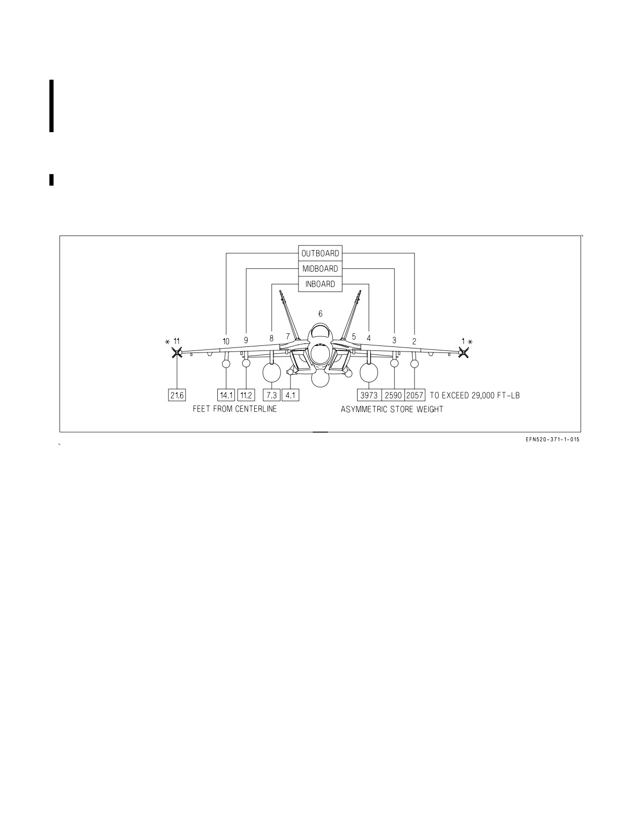
* The weight of an asymmetric missile or pod on stations 1 or 11 is not to be included in asymmetry
limitations calculations for field takeoff or in flight, but is included in landing events lateral weight
asymmetry calculations. For catapult operations, lateral asymmetry must be calculated for stations 1
thru 11 and stations 2 thru 10.
Figure 4-5. Asymmetric Stores Limitations
NOTE
• If a FUEL XFER caution is displayed and the internal wing tanks are
unbalanced, the weight of asymmetric internal wing fuel must be used
in calculating total weight asymmetry in all phases of flight. Com-
pletely split internal wing tanks (one full and one empty) have the
potential of reaching 14,000 ft-lb of lateral weight asymmetry.
• The following is a rule of thumb for calculating internal wing tank
asymmetry: pounds of fuel split x 10 (e.g., a 200 pound fuel split
equates to approximately 2,000 ft-lb of asymmetry).
• With a symmetrically loaded aircraft, release of any single store, with
the exception of a full midboard 480 gallon tank, will not exceed the
lateral weight asymmetry limitations. Release of dissimilar stores in
the normal SMS release sequence may exceed the lateral weight
asymmetry limitation.
I-4-4
ORIGINAL

A1-F18EA-NFM-000
4.1.5 AOA Limitations - Flaps AUTO. Refer to figure 4-6 for AOA limitations with flaps in AUTO.
4.1.5.1
AOA Limit Display. With MC OFP H3E AND UP, the current positive AOA limit is
displayed on the CHKLST page. The limit is displayed below the aircraft and only when a limit exists.
For every set of positive/negative AOA limits, only the positive AOA limit is displayed. The AOA limit
will be removed if the FLY lateral weight asymmetry value is removed. The AOA limit of 14° will be
displayed with flaps in HALF or FULL regardless of the lateral weight asymmetry AOA limit.
AOA Limitations - Flaps AUTO1
Lateral Weight
Subsonic
Supersonic
Asymmetry
(1,000 ft-lb)
≤6
Unrestricted
Unrestricted
(> +15° Half lateral stick or half rudder
pedal inputs only)
> 6 to ≤ 8
> 8 to ≤ 12
Low or Slow
High and Fast
(≤ 20k ft or ≤ 250
(> 20k ft and > 250
-6 to +15°
KCAS)
KCAS)
and
Unrestricted
≤ +30°
Single axis inputs only2
> 12 to ≤ 29
-6 to +15°
and
Single axis inputs only2
Notes:
(1) Rolling maneuvers up to abrupt, full stick (full stick in less than 1 second) are authorized within the
AOA and acceleration limitations specified in figure 4-7.
(2) In ‘‘Single axis inputs only’’ regions, avoid rolling or yawing the aircraft while changing longitudinal stick
position. It is acceptable to pull, stop, then roll or to pull and counter any roll-off induced by the heavy
wing under g.
(3) With MC OFP H3E AND UP, AOA tone in flaps AUTO is based on the limits in this figure and
computed lateral asymmetry. The tone indicates that the AOA lateral asymmetry limit has been
exceeded. AOA shall be reduced to stay within the limits of figure 4-6.
Figure 4-6. AOA Limitations - Flaps AUTO
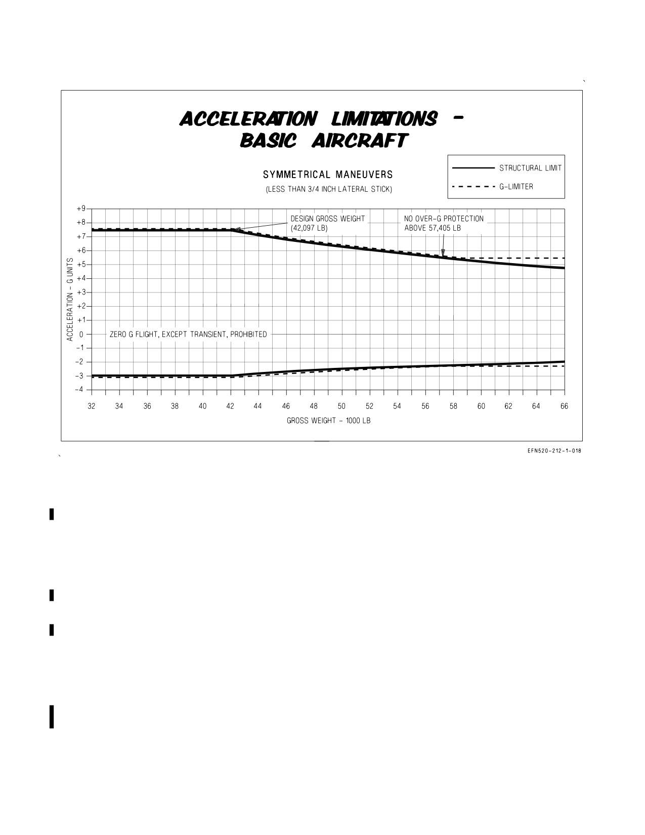
4.1.6 Acceleration Limitations. With flaps in AUTO, the acceleration limitations for the basic
aircraft (with or without empty pylons) in smooth air with the landing gear retracted are shown in
figure 4-7. In moderate turbulence, reduce deliberate accelerations 2g below that shown in figure 4-7
to minimize the potential of an aircraft over-g.
Acceleration limits during landing gear extension/retraction, or with landing gear extended, are 0.0
to +2.0g (symmetrical) and +0.5 to +1.5g (rolling).
I-4-5
ORIGINAL
A1-F18EA-NFM-000
NOTES
1. At any specific gross weight, the G-limiter will attempt to limit command g to the levels shown
above, up to 57,405 lb GW. Above 57,405 lb GW, the G-limiter is fixed at +5.5.
2. Overshoots up to +0.5g or -0.2g do not constitute an over-g.
3. Above 57,405 lb, an over-g will occur if the pilot solely relies on the G-limiter.
4.
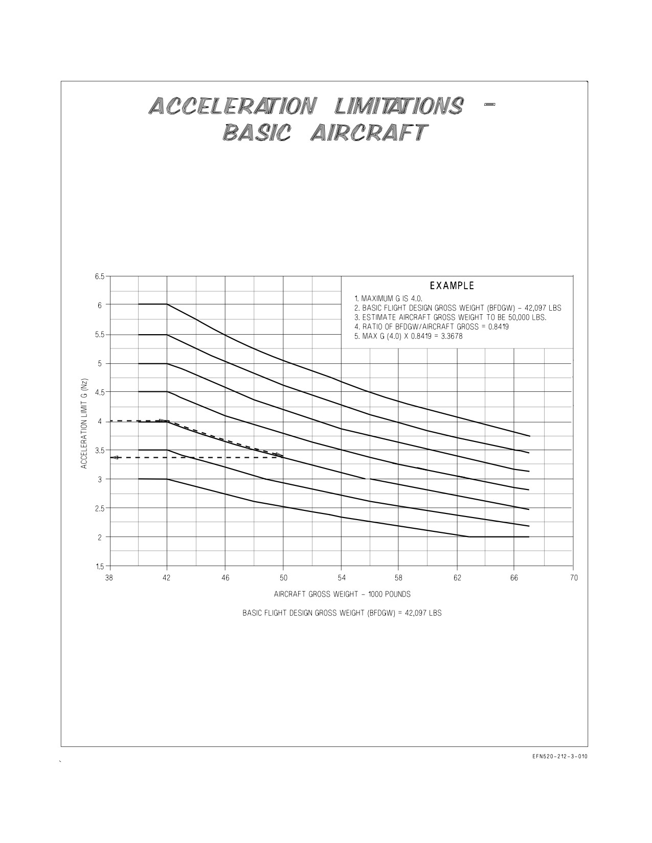
The aircraft structural carriage g envelope is based on the product of the maximum normal
acceleration limits of +7.5g and -3.0g at a weight of 42,097 lb. As aircraft gross weight increases
above 42,097 lb, Nz must be decreased so that the maximum NzW allowable is not exceeded. Refer
to sheet 3 for an example of NzW correction for these calculations. Nz limits less than +2.0 and -2.0
need not be corrected for NzW.
5.
See External Stores Limitations, A1-F18EA-TAC-020 (NWP 3-22.5-F/A18E/F VOL. IV) for
additional acceleration limitations which may apply when carrying stores. Unless otherwise noted,
Nz store limitations are based on an aircraft gross weight of 42,097 lb. As aircraft gross weight
increases above 42,097 lb, Nz must be decreased so that the maximum NzW allowable is not
exceeded. Refer to sheet 3 for an example of NzW correction for these calculations. Over-g
protection is not provided by the G-limiter for additional Nz restrictions due to store carriage.
Over-g due to store limitations will not trigger an over-g MSP code but aircraft over stress may
result. Additional store restrictions should be closely monitored by aircrew. Nz limits between +2.0
and -2.0 need not be corrected for NzW.
Figure 4-7. Acceleration Limitations - Basic Aircraft
(with or without empty pylons) (Sheet 1 of 3)
I-4-6
ORIGINAL
A1-F18EA-NFM-000
‘
NOTES
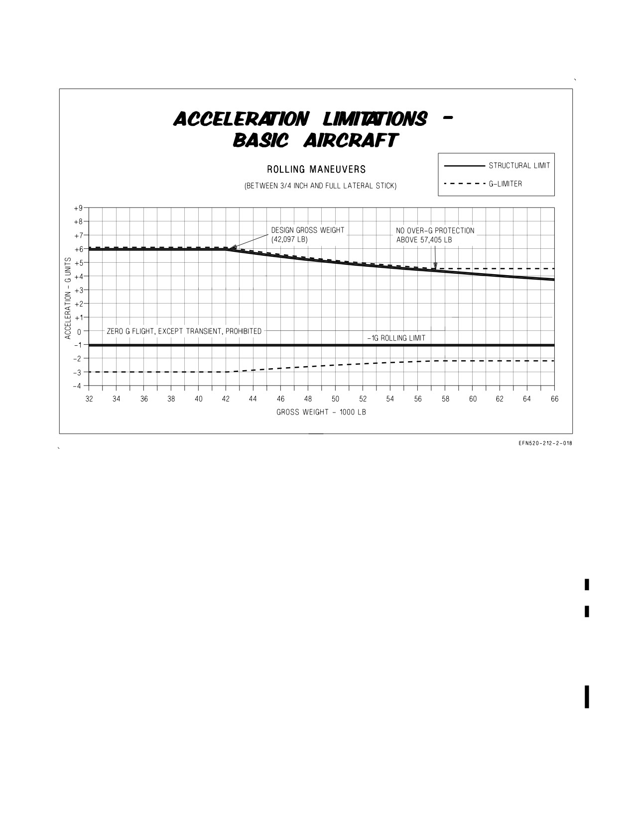
1. At any specific gross weight, the G-limiter will attempt to limit command positive g to the levels
shown above, up to 57,405 lb GW with lateral stick inputs. Above 57,405 lb GW, the G-limiter is
fixed at +4.4. For negative rolling maneuvers beyond -1 g, the G-limiter will not reduce command
g in response to lateral stick input. Negative load factor when rolling shall be closely monitored.
2. G-limiter overshoots up to +0.5g or -0.2g do not constitute an over-g.
3. Above 57,405 lb, an over-g will occur if the pilot solely relies on the G-limiter.
4. The aircraft structural carriage g envelope is based on the product of the maximum normal
acceleration limits of +7.5g and -3.0g at a weight of 42,097 lb. As aircraft gross weight increases
above 42,097 lb Nz must be decreased so that the maximum NzW allowable is not exceeded. Refer
to sheet 3 for an example of NzW correction for these calculations. Nz limits between +2.0 and -2.0
need not be corrected for NzW.
5. See External Stores Limitations, A1-F18EA-TAC-020 (NWP 3-22.5-F/A18E/F VOL. IV) for
additional acceleration limitations which may apply when carrying stores. Unless otherwise noted,
Nz store limitations are based on an aircraft gross weight of 42,097 lb. As aircraft gross weight
increases above 42,097 lb, Nz must be decreased so that the maximum NzW allowable is not
exceeded. Refer to sheet 3 for an example of NzW correction for these calculations. Over-g
protection is not provided by the G-limiter for additional Nz restrictions due to store carriage.
Over-g due to store limitations will not trigger an over-g MSP code but aircraft over stress may
result. Additional store restrictions should be closely monitored by aircrew. Nz limits between +2.0
and -2.0 need not be corrected for NzW.
Figure 4-7. Acceleration Limitations - Basic Aircraft
(with or without empty pylons) (Sheet 2)
I-4-7
ORIGINAL
A1-F18EA-NFM-000
Figure 4-7. Acceleration Limitations - Basic Aircraft
(with or without empty pylons) (Sheet 3)
I-4-8
ORIGINAL

A1-F18EA-NFM-000
4.1.7 Limitations with Flaps HALF or FULL. Refer to figure 4-8 for flaps limitations when HALF or
FULL.
Parameter
Limitation
AOA
0 to 14° (AOA tone) (1)
Bank angle
90° max
15° max during flap selection (HALF or FULL from
AUTO) with a HI AOA advisory
Acceleration
Symmetrical
0.0 to +2.0g
Rolling
+0.5 to +1.5g
NOTE:
1. Transitory excursions above 14° may be seen during catapult launch.
Figure 4-8. Limitations with Flaps HALF or FULL
4.1.8
Refueling Limitation. Maximum refueling pressure, inflight or on the ground, is
55
psi.
4.1.9
Prohibited Maneuvers.
Environmental -
1. Flight in lightning or thunderstorms.
Systems -
1. Takeoff with a FADEC DEGD indication (dual channel line outs).
2. Takeoff with a FCS A or FCS B DEGD.
3. Pulling any FCS circuit breaker inflight except as directed by NATOPS.
4. Use of RALT mode below 500 feet AGL.
5. Use of the auto sever/redeployment function of the ALE-50.
6. Landing with autopilot modes engaged except for the following:
a. Mode 1 ACL.
b. Field landings with FPAH/ROLL.
7. Takeoffs and landings while using any laser eye protection (LEP) devices.
I-4-9
ORIGINAL
A1-F18EA-NFM-000
8. Selection of MAN with the ECS MODE switch.
Selection of MAN with the ECS MODE switch while the aft cooling fan
shutoff valve is open may cause the fan to overspeed resulting in a
catastrophic fan failure potentially leading to loss of OBOGS.
9. Flight in RVSM controlled airspace with any of the following:
a. Mach > 0.92
b. AOA > 15°
c. Load factor > 2g
d. Initial engagement of BALT when above Mach 0.90
e. BALT not engaged when level at assigned altitude (During formation flight, BALT engage-
ment is only required by the flight leader.)
f. Refueling probe extended
g. GAIN ORIDE selected
h. Suspected AOA or pitot-static probe damage (e.g., birdstrike, refueling basket strike)
i. Baro altitude displayed with an ″X″
10. In-flight Memory Inspect (MI) of FCC (UNIT 14 or 15) addresses (ADDR) greater than six
digits long.
In-flight Memory Inspect (MI) of FCC (UNIT 14 or 15) addresses
(ADDR) greater than six digits long may cause all four FCC channels to
shut down which will result in loss of aircraft control.
Departure/Spin -
1. Zero airspeed tailslides.
2. Intentional departures/spins.
3. Yaw rates over 40° second (yaw tone).
4. Holding roll inputs (lateral stick or rudder pedal) past 360° of bank angle change.
5. Inflight selection of RCVY on the SPIN switch.
Selection of manual spin recovery mode (SPIN switch in RCVY) seri-
ously degrades controllability and prevents recovery from any departure
or spin.
I-4-10
ORIGINAL W/IC 34
A1-F18EA-NFM-000
Fuel and Engine Oil -
1. Zero g except transient (over 2 seconds between +0.2 and -0.2g).
2. Negative g for more than 10 seconds (30 seconds required between negative g maneuvers).
Loads -
1.
Field full stop, FCLP, or T&G with lens settings greater than 3.25°.
2.
Carrier arrestment or T&G with lens settings greater than 4.0°.
3.
Pushing beyond -1g above 700 KCAS and below 10,000 feet MSL.
4.
Holding lateral stick inputs past 180° of bank angle change when pushing between 0.0 and -1.0g.
5.
Abrupt, full aft stick inputs (full aft stick in less than 0.5 seconds) with less than 3,500 pounds of
fuel.
6.
AUX release of external fuel tanks or aerial refueling store.
7.
Lateral and directional trim limitations. Use of lateral and/or directional trim in
combination with lateral stick inputs above certain airspeeds may result in the exceedance of
aircraft structural load limitations. Following are four conditions that require trim due to aircraft
imbalance and their associated limitations. These limitations are in addition to existing
limitations for the basic aircraft and any store peculiar limitation. Air to ground limitations are
for any configuration with a wing EFT or wing carried air to ground store.
Condition A: Roll off tendency > 5°/sec without lateral trim or
FLIR pod loading only on one side of the aircraft without a centerline 480 EFT
Condition B: Lateral weight asymmetry for air-to-air weapons > 6,000 ft-lb and ≤ 14,000 ft-lb
Condition C: Lateral weight asymmetry for to air-to-ground weapons > 6,000 ft-lb and ≤29,000
ft-lb
Condition D: Lateral weight asymmetry for to air-to-air weapons > 14,000 ft-lb
Flight Restrictions
A
B
C
D
Airspeed > 500KCAS
X
X
X
X
Symmetric Nz = -1.2 to +7.5g
Airspeed > 600 KCAS or IMN > 1.1 below 24,000 ft MSL
X
X
Airspeed > 500 KCAS above 24,000 ft MSL
1/2 Lateral Stick Deflection
Airspeed > 600 KCAS or IMN > 1.05
X
non-abrupt 1/2 lateral stick deflections
All airspeeds except for powered approach, 1/2 lateral stick input
X
These limitations assume that the aircraft is configured with ECP 6171 or IAFC 362
(aft fuselage stiffener).
I-4-11
ORIGINAL W/IC 34
A1-F18EA-NFM-000
Without this modification there are additional limitations that are defined below:
Configuration
Restriction
IMN between 0.9 and 1.04
For aircraft with asymmetry due to air to air weapons ≤ 8,000 ft-lb
Symmetric Nz = -3.0 to +7.5g
Asymmetric Nz = -1.0 to +5.0g
For aircraft with roll off tendency >5°/sec without lateral trim
IMN between 0.9 and 1.04
For aircraft with a FLIR pod only on one side of the aircraft without a
Symmetric Nz = -3.0 to +5.0g
centerline tank
Asymmetric Nz = -1.0 to + 1.5g
For aircraft with lateral weight asymmetry > 8,000 ft-lb due to air-to-air
stores
For aircraft with lateral weight asymmetry > 6,000 ft-lb due to air-to-
ground stores
8. Any rudder input when aircraft load factor is less than -1.2g.
Flutter -
1. Flight without LAU-127 wingtip launcher rails. The launchers on both stations 1 and 11 shall be
either: (a) LAU-127A/A or B/A (with power supply and nitrogen bottle installed), or (b) LAU-
127C/A (with power supply and High Pressure Pure Air Generator (HiPPAG) unit installed).
Flying Qualities -
1. Single-ship takeoffs with 90° crosswind component over 30 knots.
2. Section takeoffs with any of the following conditions:
a.
90° crosswind component over 15 knots.
b. Asymmetric loading over 9,000 ft-lb not including wingtip missiles or pods.
c. Dissimilar loading except pylons, FLIR, LDT, fuselage missiles, wingtip missiles or pods,
CVERS, MERS, or TERS.
3. Flight with GAIN ORIDE selected above 10° AOA or above 350 KCAS (flaps AUTO), 200 KCAS
(flaps HALF), or 190 KCAS (flaps FULL).
With GAIN ORIDE selected (fixed FCS gains), the aircraft is uncontrol-
lable above approximately 450 KCAS.
4. Single-ship landings with 90° crosswind component over 30 knots.
5. Section landings with 90° crosswind component over 15 knots.
6. Aerobraking on landing rollout with crosswind greater than 5 knots, pitch attitude greater than
10°, airspeed less than 80 KCAS, GAIN ORIDE selected, FCS AIR DAT caution or FLAP
SCHED caution.
I-4-12
ORIGINAL
A1-F18EA-NFM-000
4.2 EXTERNAL STORES LIMITATIONS
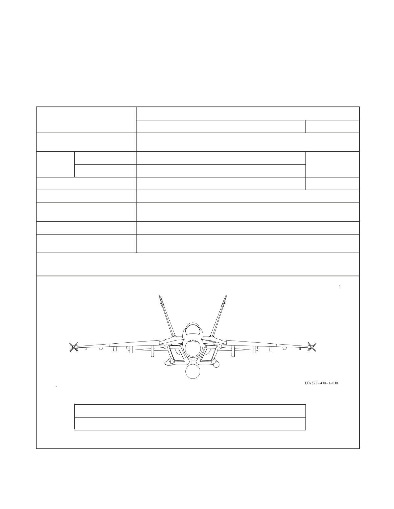
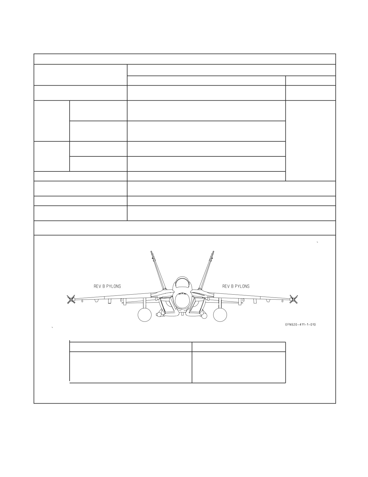
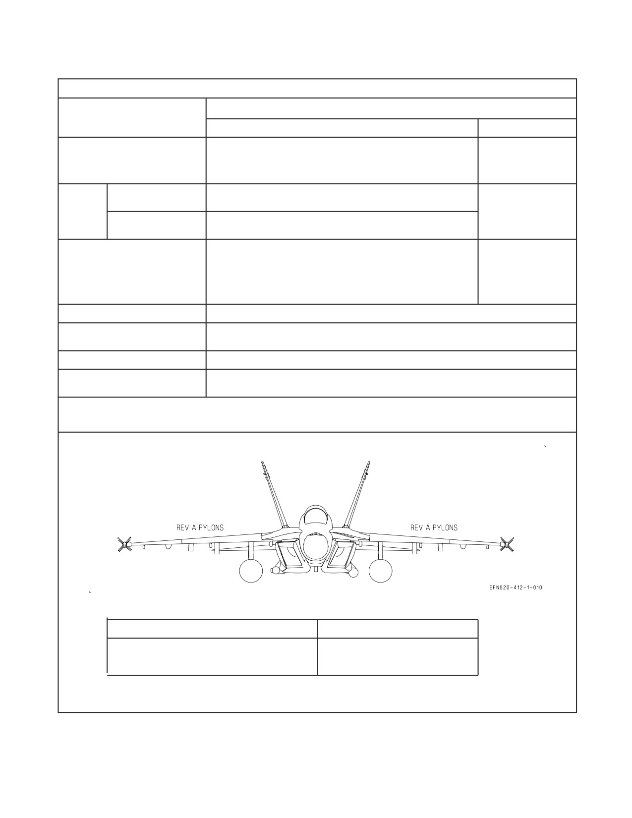
External stores limitations for external fuel tanks are provided in figures 4-9 thru 4-11. Figure 4-12
contains Air Refueling Store Carriage Limits. Figures 4-9 thru 4-12, in conjunction with the Tactical
Manual, A1-F18EA-TAC-020 (NWP 3-22.5-F/A18E/F Vol IV) define the stores limitations for all
(external fuel tanks and other) external stores. Only those pylons and stores shown in the Tactical
Manual may be carried and/or released.
Fuel in Tank
LIMITATIONS
(weight/tank)
>500 lb
≤ 500 lb
Airspeed
LON
(KCAS/IMN)
Load
Symmetrical
LON
Factor
LON
(g)
Rolling
LON (1)
Lateral Stick Deflection
LON (1)
LON
Rudder
LON
Field Landing, FCLP,
Any fuel state
T&G, Field Arrest
Catapult
Less than or equal to 100 lb or greater than 2,700 lb
Carrier Arrestment,
Less than or equal to 800 lb
Carrier T&G
NOTE:
1. Lateral stick inputs are restricted to checks to neutral only to terminate rolls. Abrupt full lateral stick deflection authorized for roll
initiation.
Simplified Limitations Schematic
> 500 lb Fuel
D Roll termination only to neutral. No opposite lateral stick check allowed.
Figure 4-9. Station 6 480-Gal External Fuel Tank Carriage Limits
I-4-13
ORIGINAL
A1-F18EA-NFM-000
SUU-79B/A (Rev B) Wing Pylons, AFC-315 to Lot 22 aircraft
LIMITATIONS
Fuel in Tank
(weight/tank)
>500 lb
≤ 500 lb
Airspeed
635/1.6 above 15,000 ft MSL
635/1.6
(KCAS/IMN)
570 KCAS at or below 15,000 ft MSL
Symmetrical
LON at or below 500 KCAS
-3.0 to +6.0 from 500 KCAS up to 550 KCAS
Load
-1.0 to +4.0 above 550 KCAS (1)
Factor
(g)
Rolling
LON (rolling) at or below 400 KCAS
-1.0 to +2.0 above 400 KCAS and below 470 KCAS (1)
+1.0 to +2.0 above 470 KCAS (1)
LON
At or below
LON at or below 470 KCAS
Lateral
15,000 ft MSL
Smooth inputs of up to 3/4 inches above 470 KCAS
Stick
Deflection
LON at or below 570 KCAS
Above 15,000 ft MSL
Smooth inputs of up to 3/4 inches above 570 KCAS
Rudder
Smooth inputs above 500 KCAS
Field Landing, FCLP,
Any fuel state
T&G, Field Arrest
Catapult
Less than or equal to 100 lb or greater than 2,700 lb
Carrier Arrestment,
Less than or equal to 800 lb
Carrier T&G
NOTE:
1. Nz restriction due to carriage of 480
EFT need not be corrected for an aircraft weight greater than 42,097 lb (NzW).
Simplified Limitations Schematic
> 500 lb Fuel
≤ 500 lb Fuel
D Max Airspeed 570 KCAS/1.6 IMN
D Max Airspeed 635 KCAS/1.6 IMN
D LON at or below 400 KCAS
D Single Axis Control inputs above 400 KCAS
(roll then pull)
D 4g Max above 500 KCAS
Note: The simplified limitations are presented as a rule-of-thumb for ease of memorization.
The actual NATOPS limits are shown in the upper portion of the table.
Figure 4-10. Station 4/8 480-Gal External Fuel Tank Carriage Limits (Rev B Pylons)
I-4-14
ORIGINAL
A1-F18EA-NFM-000
SUU-79A/A (Rev A) Wing Pylons
LIMITATIONS
Fuel in Tank
(weight/tank)
>500 lb
≤ 500 lb
Airspeed
550/1.6 above 15,000 ft MSL
600/1.3 without
(KCAS/IMN)
520 KCAS at or below 15,000 ft MSL
FLIR Pod
570/1.3 with FLIR
Pod
Symmetrical
-3.0 to +3.0 at or below 475 KCAS
Load
0 to +2.0 above 475 KCAS (1)
Factor
LON
(g)
Rolling
-1.0 to +2.0 at or below 325 KCAS
0 to +2.0 above 325 KCAS (1)
LON without FLIR
Pod
Lateral
LON at or below 225 KCAS
Smooth inputs of up
Stick
Half between 225 and 325 KCAS
to 3/4 inches above
Deflection
Smooth inputs of up to 3/4 inches above 325 KCAS
550 KCAS with
FLIR Pod
Rudder
Smooth inputs above 500 KCAS
Field Landing, FCLP,
Any fuel state
T&G, Field Arrest
Catapult
Less than or equal to 100 lb or greater than 2,700 lb
Carrier Arrestment,
Less than or equal to 800 lb
Carrier T&G
NOTE:
1. For load factor restrictions resulting in an aircraft envelope less than or equal to 2.5 g for symmetric and 2.0 g for rolling, no further
reduction in load factor is required as a result of aircraft weight being greater than basic flight design gross weight.
Simplified Limitations Schematic
> 500 lb Fuel
≤ 500 lb Fuel
D Max Airspeed 520 KCAS/1.6 IMN
D Max Airspeed 570 KCAS/1.3 IMN
D Navigational Turns Only
D LON up to 550 KCAS
(Ferry Jet or Tanker)
Note: The simplified limitations are presented as a rule-of-thumb for ease of memorization.
The actual NATOPS limits are shown in the upper portion of the table.
Figure 4-11. Station 4/8 480-Gal External Fuel Tank Carriage Limits (Rev A Pylons)
I-4-15
ORIGINAL

A1-F18EA-NFM-000
LIMITATIONS
Station 6 ARS
Station 6 ARS, Station 3/4/8/9
(weight/tank)
Stowed and feathered
480-Gal Carriage (5-wet)(1)
Altitude (ft MSL)
0 to 40,000
Airspeed (KCAS/IMN)
575/0.92
430/0.8 (2)
Load
Symmetrical
-1.0 to +4.0 (3)
Factor
LON
(g)
Rolling
-1.0 to +3.0 (3,4)
Full with any air to ground store
or
Lateral Stick
an EFT on any wing station
Deflection
Simultaneously large and abrupt
(roll limiting on);
multi-axis inputs prohibited (4,5)
otherwise Half (6)
Rudder
LON
Angle of Attack
Flaps AUTO: -6° to + 15°
LON
Flaps HALF or FULL: LON
Field Landing, FCLP,
Any fuel state
T&G, Field Arrest
ARS: ≤ 100 lb or > 1,700 lb fuel
Catapult
≤ 100 lb or > 1,700 lb fuel
480-gal EFT: ≤ 100 lb or > 2,700 lb fuel
Carrier Arrestment,
≤ 500 lb fuel
ARS and/or Station 3/9 480-gal
Carrier T&G
EFT: ≤ 500 lb fuel
Station 4/8 480-gal EFT: ≤ 800 lb fuel
NOTES:
1. SUU-79 B/A (Rev B) Wing Pylons, AFC-315 to Lot 22 aircraft.
2. Abnormal wing tank fuel transfer sequence: If fuel is transferred (because of a failure condition) from
Station 4/8 tanks before the Station 3/9 tanks are empty, then airspeed limit is 300 KCAS/0.6 IMN,
whichever is less.
3. Nz is based on an aircraft GW of 66,000 lb. When aircraft gross weight is greater than 66,000 lb, reduce
symmetric load factor allowable to -0.5 to +3.5 and rolling load factor allowable to -0.5 to +2.5
4. Lateral stick input is restricted to half when the fuel in Station 3/9 is greater than 1,600 lb/tank. This
restriction is not applicable when in power approach configuration.
5. Large is defined as greater than half maximum input. Abrupt is defined as a control input rate of
maximum deflection in less than 1 second. Multi-axis is defined as simultaneous longitudinal, lateral, or
directional control inputs. A multi-axis input is allowed as long as it is not large and abrupt.
6. Half lateral stick displacement restriction does not apply when in power approach configuration.
Figure 4-12. Air Refueling Store Carriage Limits
I-4-16
ORIGINAL

A1-F18EA-NFM-000
4.2.1 ARS Limitations
1. ARS operating limitations are listed in figure 4-13.
Limitation
Limitation
Condition
(P/N 31-301-48310-2)
(P/N 31-301-48310-3)
EFT loading
Station 4/8 only (3 wet)
Station 4/8 (3 wet)
Station 3/4/8/9 (5 wet)
Altitude
0 to 35,000 feet MSL
Power on
180 to 300 KCAS
(RAT unfeathered)
180 to 250 KCAS
(<5,000 feet MSL)
180 to 260 KCAS
Hose extension
180 to 250 KCAS
180 to 275 KCAS
(5,000 to 10,000 feet MSL)
180 to 275 KCAS
(>10,000 feet MSL)
Hose extended
180
to 300 KCAS/0.80 IMN max
Fuel transfer to receiver
180 to 300 KCAS/
225 to 300 KCAS/0.80 IMN max
0.80 IMN max
180 to 250 KCAS
(<5,000 feet MSL)
180 to 200 KCAS
180 to 260 KCAS
Hose retraction
(<25,000 feet MSL)
180 to 275 KCAS
(5,000 to 10,000 feet MSL)
180 to 210 KCAS
(≥25,000 feet MSL)
180 to 275 KCAS
(>10,000 feet MSL)
Figure
4-13. ARS Operating Limitations (Sheet 1 of 2)
2. Prohibited maneuvers with ARS installed:
a. Placing the LTD/R switch to ARM.
b. Afterburner operation with the hose extended.
3. ARS carriage limitations are listed in figure 4-12.
4. ARS operating limitations for P/N 31-301-48310-4 and -5 are as follows:
I-4-17
ORIGINAL

A1-F18EA-NFM-000
Condition
Limitation (P/N 31-301-48310-4/5)
Station 4/8
Station 3/4/8/9
EFT loading
(3 wet)
(5 wet)
Altitude
0 to 35,000 feet MSL
Power on
220-300 KCAS
(RAT unfeathered)
180 to 275 KCAS
180 to 250 KCAS
(<5,000 feet MSL)
(<5,000 feet MSL)
190 to 275 KCAS
190 to 260 KCAS
(5,000 to 7,500 feet MSL)
(5,000 to 7,500 feet MSL)
200 to 275 KCAS
200 to 260 KCAS
Hose extension/
(7,501 to 10,000 feet MSL)
(7,501 to
10,000
feet MSL)
retraction
200-275 KCAS
10,001 to 15,000 feet MSL
220-275 KCAS
15,001 to 35,000 feet MSL
Hose extended
180 to 300 KCAS/0.80 IMN max
180 to 300 KCAS/0.80 IMN max
(<5,000 feet MSL)
190 to 300 KCAS/0.80 IMN max
(5,000 to 7,500 feet MSL)
Fuel transfer to
receiver
200 to 300 KCAS/0.80 IMN max
(7,501 to 15,000 feet MSL)
220 to 300 KCAS/0.80 IMN max
15,001 to 35,000 feet MSL
Figure 4-13. ARS Operating Limitations (Sheet 2)
5. Prohibited maneuvers with ARS installed:
a. Placing the LTD/R switch to ARM.
b. Afterburner operation with the hose extended.
6. ARS carriage limitations are listed under External Stores Limitations.
I-4-18
ORIGINAL
A1-F18EA-NFM-000
4.2.2 ATFLIR Limitations
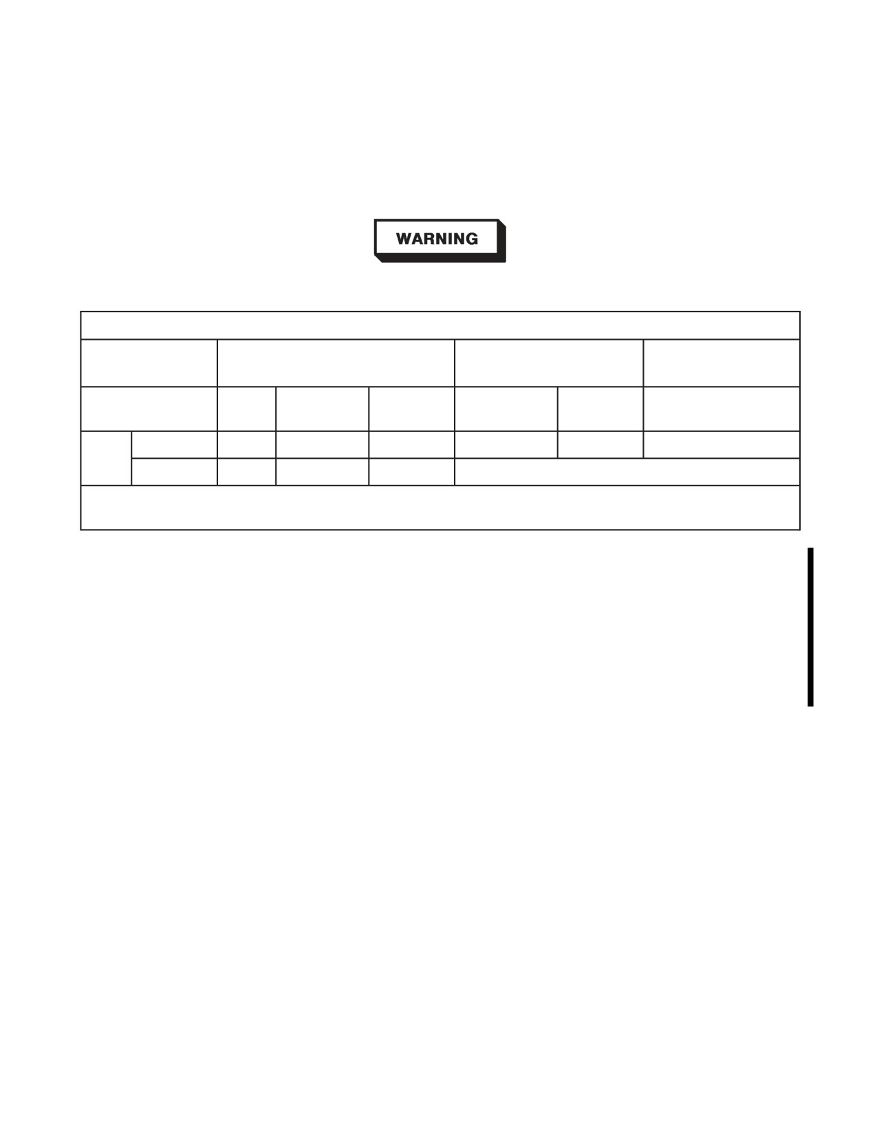
1. These limits are ATFLIR specific, apply to any ATFLIR configuration without inboard 480
gallon tanks, and do not pertain to asymmetric loads. ATFLIR limitations are listed in
figure 4-14.
Failure to use eye protection when firing the LASER may result in severe
eye damage and possible blindness.
ATFLIR Limitations
Between 10,000 and 18,000
Altitude
< 10,000 feet MSL
> 18,000 feet MSL
feet MSL
Airspeed
Between
< 550
> 600
< 550
> 550
LON
(KCAS)
550 and 600
Symmetric
LON
-3.0 to +7.0
-1.0 to 4.0
LON
-3.0 to 7.0
LON
Nz
(g’s)
Rolling
LON
-1.0 to +4.0
(1)
LON
NOTE:
1. Smooth inputs up to ¾ inch deflection for navigational turns or as required to maintain roll attitude.
Figure 4-14. ATFLIR Limitations
4.3 OPERATING LIMITATIONS (LOT 21)
4.3.1
Prohibited Maneuvers
Systems -
1. Flight in RVSM controlled airspace.
I-4-19
ORIGINAL
A1-F18EA-NFM-000
4.4 AESA RADAR LIMITATIONS
Flight testing of the AN/APG-79 AESA radar has shown that this system can interfere with, and
significantly degrade the performance of, various precision approach systems including PAR and
ACLS. Aircrew operating AN/APG-79 AESA equipped aircraft shall be aware that directing
AN/APG-79 AESA transmissions toward landing facilities (ship or shore) may cause strong electro-
magnetic interference (EMI) affecting the safety of aircraft on approach. To the maximum extent
possible, aircrew shall avoid directing AN/APG-79 AESA radar transmissions towards facilities with an
operating active PAR or ACLS (shipboard or shore-based). Unless specifically authorized for
operational necessity or required for safety of flight, aircrew should cease AN/APG-79 AESA radar
transmissions whenever operating within 10 nm of PAR and ACLS facilities during IMC/Case III
conditions.
• AN/APG-79 AESA radar transmissions specifically directed towards
an operating PAR or ACLS within 10 nm have caused strong electro-
magnetic interference (EMI) with these radar-based systems and
caused intermittent, unannunciated anomalies that resulted in erro-
neous azimuth/glideslope commands being sent to aircraft on precision
approach, increasing the risk of controlled flight into terrain (CFIT).
Proper flight instrument crosscheck using all available means
(TACAN, DME, and RADALT) is essential for all aircraft during PAR
and ACLS approaches to detect abnormal precision approach param-
eters.
• The AGR mode of the AN/APG-79 AESA radar was observed to cause
some of the highest levels of EMI on affected PAR and ACLS systems.
Ensure the AN/APG-79 radar is in SIL, STBY, or OFF prior to
selection of TDC to the HUD in order to enable the steering dot in the
center of the velocity vector (which commands AGR).
• AN/APG-79 AESA radar transmissions within 10 nm directed towards
civil airfields operating ASDE-X ground traffic management systems
have caused EMI. ASDE-X is an FAA-designed, radar-based system
designed to reduce runway incursions by tracking departing, arriving,
and taxiing aircraft plus ground vehicles at major civilian airfields.
AN/APG-79 AESA-generated EMI results in ASDE-X system shut-
down, increasing the risk to taxiing aircraft and airport vehicles of
unintentional ground or runway incursion.
NOTE
AN/APG-79 AESA radar does not interfere with SPN-41 ICLS systems
or non-precision radar approach systems (ASR). AN/APG-79 has not
been tested against other civil systems (ILS).
I-4-20
ORIGINAL W/IC 33
A1-F18EA-NFM-000
NOTE
• Adverse EMI effects from AN/APG-79 AESA equipped aircraft acting
as overhead/recovery tankers (not on approach) have been observed
during SPN-42 and SPN-46 ACLS testing.
• The SPN-42 (shore-based ACLS) and SPN-46 (shipboard ACLS) have
shown degraded lock-on and command guidance anomalies due to
EMI interference from AN/APG-79 AESA radar transmisisons. For
the SPN-46 system, these anomalies are more severe and more
probable with the Block 1 Upgrade to the SPN-46 system.
• Through 2011, the FAA has stated the ASDE-X system will be fielded
at the following locations: KATL, KBDL, KBOS, KBWI, KCLT,
KDCA, KDEN, KDFW, KEWR, KFLL, KHIK, KHOU, KIAD,
KIAH, KJFK, KLAX, KLGA, KLSV, KMCO, KMDW, KMEM,
KMIA, KMKE, KMSP, KORD, KPHL, KPHX, KPVD, KSAL,
KSAN, KSDF, KSEA, KSNA, and KSTL.
I-4-21
(Reverse Blank)
ORIGINAL W/IC 33
A1-F18EA-NFM-000
PART II
INDOCTRINATION
Chapter
5 - Indoctrination
61
(Reverse Blank)
ORIGINAL
A1-F18EA-NFM-000
CHAPTER 5
Indoctrination
5.1 INITIAL QUALIFICATION
Initial NATOPS qualification in F/A-18E/F series aircraft shall be obtained by satisfactory
completion of the CNO approved course of instruction at an F/A-18E/F Fleet Replacement Squadron
(FRS). The minimum training requirements to be completed prior to initial NATOPS qualification for
pilots and weapon system operators (WSO) are set forth below.
5.1.1 Minimum Ground Training Requirements. The following minimum ground training require-
ments shall be successfully completed prior to first flight in an E/F-series aircraft:
1. FRS academic familiarization syllabus to include:
a. Aircraft systems and procedures.
b. Emergency procedures review.
c. Instrument flight training.
d. Immediate action, open, and closed book NATOPS exams.
e. Cockpit orientation.
f. Ejection, egress, and survival equipment checkout.
g. Preflight checkout.
2. FRS simulator familiarization syllabus in the Tactical Operational Flight Trainer (TOFT).
5.1.2 Minimum Flight Training Requirements. The following minimum flight training require-
ments shall be successfully completed prior to initial NATOPS qualification:
1. FRS familiarization flight phase to include a minimum of 10 hours first pilot time (FPT) in
E/F-series aircraft (5 hours if currently NATOPS qualified in F/A-18A-D), and a minimum of 10
hours special crew time (SCT) (5 hours if currently NATOPS qualified in F/A-18B/D) in F-series
aircraft for WSOs.
5.2 FOLLOW-ON TRAINING
Follow-on ground training for each activity may vary according to local conditions, field facilities,
requirements from higher authority, and the immediate unit Commanding Officer’s estimate of
squadron readiness.
Follow-on flight training should include aircraft and weapon systems instruction, normal and
emergency procedures, simulators
(if available), and evaluation of aircrew performance. Local
command requirements, squadron mission, and other factors may influence the actual flight training
syllabus and the sequence in which it is completed.
II-5-1
ORIGINAL

A1-F18EA-NFM-000
5.3
CURRENCY REQUIREMENTS
Minimum requirements to maintain currency after initial qualification shall be established by the
unit Commanding Officer but will involve no less than 5 hours of first pilot time and two takeoffs and
landings in E/F-series aircraft in the previous 90 days for pilots, and 5 hours of special crew time in
F-series aircraft in the previous 90 days for WSOs. Additionally, an annual NATOPS evaluation with
a grade of at least conditionally qualified is required for both pilots and WSOs.
5.3.1 Regaining Currency. Requalification of those crewmembers whose currency has lapsed shall
include a familiarization flight(s), to include enough flight time to enable crewmembers to attain the
requirement of 5 flight hours and 2 takeoff and landings in E/F series within 90 days. Specifics of
familiarization flight(s) at discretion of Commanding Officer of the unit having custody of the aircraft.
5.4 REQUIREMENTS FOR VARIOUS FLIGHT PHASES
The specific requirements for various flight phases conducted during initial training in E/F-series
aircraft are listed in figure 5-1.
Pilots with current
NATOPS in
Type/Model, and
Flight Phase
Pilot General
WSO
F/A-18 CAT1 or CAT2
transition syllabus
complete
Day Solo/Crew Solo
4 FAM flights *
1 FAM flight *
Night Solo/Crew Solo
Day Solo/Crew Solo qualified, 1 night FAM flight
Solo/Crew Solo Cross
F/A-18E/F instrument and NATOPS qualified
Country
Initial CQ
50 F/A-18E/F hours
NATOPS Qualified
15 F/A-18E/F hours
(FPT)
(FPT)
* CNO approved syllabus
Figure 5-1. Requirements for Various Flight Phases During Initial Training
5.4.1 Instrument Evaluation Flights. Instrument evaluation flight requirements are delineated in
OPNAVINST 3710.7 series and the NATOPS Instrument Flight Manual. Instrument evaluation
flights may be conducted by designated military aviators or Naval Flight Officers designated in writing
by their Commanding Officer.
5.4.2 Instrument Qualification. In accordance with OPNAVINST 3710.7 series, instrument ratings
shall be valid in all aircraft in which the pilot is instrument qualified regardless of the model in which
the check was flown. A pilot may be considered to be instrument qualified in an aircraft when he/she
has completed the evaluation as outlined in each respective NATOPS manual and has met the
requirements for an instrument rating as outlined in OPNAVINST 3710.7 series.
II-5-2
ORIGINAL

A1-F18EA-NFM-000
5.4.2.1
Requirements for Instrument Qualification in E/F-Series Aircraft. Each aircrew is required
to be instrument qualified in F/A-18E/F series aircraft.
Pilots must have a current instrument rating prior to flight in actual instrument conditions. Figure
5-2 delineates the pilot requirements for instrument qualification along with ceiling and visibility
restrictions for instrument rated pilots. When a pilot becomes fully instrument qualified in F/A-18E/F
series aircraft, the ceiling and visibility requirements shall be the minimums authorized by
OPNAVINST 3710.7 series, namely field minimums not less than 200/½.
WSOs must attend instrument ground school and satisfactorily complete a written examination to
be instrument qualified.
5.4.3 Ceiling/Visibility Requirements. The ceiling and visibility requirements for takeoff and
landing for pilots who are not fully instrument qualified in E/F-series aircraft are delineated in figure
5-2.
Pilot With Current
Pilot With Current
Instrument Rating,
F/A-18E/F Actual
Instrument Rating
Pilot With Current
F/A-18A-D NATOPS
Flight Experience
and >500 Hours in
Instrument Rating
Qualification and
Tactical Aircraft
>300 hours in model
IP in rear of F(T)
300/1
1000/3 for takeoff/
None
landing, and training in
clear air mass
Remain VMC and VFR
Circling mins for takeoff/
Complete 1st FAM
landing, and training in
flight *
clear air mass
1000/3 for takeoff/
Complete 2nd FAM
F/A-18E/F instrument
landing, and training in
Remain VMC and VFR
flight *
qualified
clear air mass
Complete 2nd FAM
Circling mins for takeoff/
1000/3 for takeoff/
flight *, and IAC in rear
−
landing, and training in
landing, and training in
cockpit or complete all
clear air mass
clear air mass
FAM flights * ++
F/A-18E/F NATOPS
Circling mins for
F/A-18E/F instrument
check and >10 hours
−
takeoff/landing, and
qualified
(FPT)
training in clear air mass
F/A-18E/F NATOPS
F/A-18E/F instrument
check and >40 hours
−
−
qualified
(FPT)
* CNO approved syllabus
++ Excluding CQ introduction
Figure 5-2. Pilot Ceiling and Visibility Restrictions Prior to Instrument Qualification
II-5-3
ORIGINAL
A1-F18EA-NFM-000
5.5 WAIVERS
Unit Commanding Officers are authorized to waive, in writing, minimum flight and/or training
requirements in accordance with OPNAVINST 3710.7 series.
5.6 PERSONAL FLYING EQUIPMENT
The minimum requirement for personal flying equipment is contained in OPNAVINST 3710.7
series. In addition, all F/A-18E/F aircrew shall use the latest available flight safety and survival
equipment authorized by the Aircrew Personal Protective Equipment Manual (NAVAIR 13-1-6).
II-5-4
ORIGINAL
A1-F18EA-NFM-000
PART III
NORMAL PROCEDURES
Chapter
6 - Flight Preparation
Chapter
7 - Shore-Based Procedures
Chapter
8 - Carrier-Based Procedures
Chapter
9 - Special Procedures
Chapter 10 - Functional Checkflight Procedures
63
(Reverse Blank)
ORIGINAL
A1-F18EA-NFM-000
CHAPTER 6
Flight Preparation
6.1 MISSION PLANNING
6.1.1 General. All aircrew shall be responsible for preflight planning and preparation of required
charts, route navigation computations including fuel planning, checking weather and NOTAMS, and
for filing required flight plans. Refer to Part XI, Performance Data or approved fuel planning software,
to determine fuel consumption and profile. Planned minimum on deck fuel should not be less than
1,800 lb. The aircrew shall refer to applicable tactical publications to plan specialized missions.
6.1.2 Flight Codes. The proper flight classification and flight purpose codes to be assigned to
individual flights are established by OPNAVINST 3710.7 (Series).
6.2 BRIEFING/DEBRIEFING
6.2.1 Briefing. The flight leader is responsible for the briefing of each aircrew in the flight on all
aspects of the mission to be flown. A standard briefing guide shall be used in conducting the briefing.
Briefs shall include applicable ADMIN, TAC ADMIN, and MISSION CONDUCT. Aircrew qualified
to assume the mission lead shall record all data necessary to complete the mission. The briefing guide
should include the following:
6.2.1.1
NATOPS Admin Briefing Guide
General
Time hack
Objectives
Mission (Primary, Secondary)
Training
Julian date, event number
Times
Walk
Start
Check In
Taxi
Takeoff
Land
Debrief
Line up
Callsigns
Aircraft assigned
Crew (Msn Commander, Alternate Lead)
A/A TACAN
Radar channels, search block
Loadout Gross Weight, Max Trap
Comm Plan
Frequencies
III-6-1
ORIGINAL
A1-F18EA-NFM-000
Controlling Agencies
IFF Procedures
Alpha Check
Waypoint Plan
Weather, NOTAMs
Launch, Mission, Recovery, Divert
Sunrise, Sunset, Moonrise, Moonset
Water / Air Temperature
Joker / Bingo / Fuel Ladder
Preflight
Aircraft
Ordnance
Ground / On-deck
Line / Deck and Start Procedures
Final checks
Clearance
Arming
Marshal
Taxi
Takeoff / Launch
Duty Runway / Ships Heading
Ships Posit, PIM
Type Takeoff / Case Departure
Takeoff Data (NWLO, T/O, Abort speeds, Distance)
Catapult Endspeed, Trim (asymmetrical)
Takeoff Checks
Departure Procedures
En Route
Rendezvous (Location, Speed)
En Route Formation
Route of Flight
Op Area
Range Info, Altitudes, Restrictions
Target Time, Range Event Number
Controlling Agency
Entry / Exit procedures
RTB / Recovery
Rendezvous (Location, Speed)
Battle Damage Checks
III-6-2
ORIGINAL
A1-F18EA-NFM-000
Formation
Controlling Agency
Route of Flight
Airfield Recovery Procedures
Ship Recovery Procedures
Case Recovery
Marshal
Recovery Time
Type entry
Overhead, Break Interval
Straight-In / GCA
Type Landing
Post Landing
Clearing Landing Area
Configuration Changes
Comm
Taxi
De-Arming
Parking (Line / Hotpits / Hotseat)
Contingencies
Allowable Slide Time
Go / No Go Criteria
Fallouts, Spares
Bent Radar / Sensor / Weapon
Hung / Unexpended Ordnance
Weather
Emergencies
Abort, Field Arrestment
Loss of Brakes, Emergency Cat Flyaway
Inflight Emergencies / System Failures
NORDO, Lost Comm / Lost Sight
Midair, Bird Strike
Divert / BINGO
Ejection / SAR
ORM
Training Rules
ACM
NVG
LAT
LATT
III-6-3
ORIGINAL
A1-F18EA-NFM-000
Aircrew Coordination
Refer to Chapter 28.
6.2.1.2
NATOPS Tactical Admin Briefing Guide.
Environmentals
Sun / Moon
Winds
Conning Altitudes, Conn Check
Cloud cover
Decks (Hard / Soft)
Weapons Checks
G-warm, Inverted Check
Expendables Check
Fence Checks Complete
CVRS - Tapes
Knock It Off / Terminate Calls
Fuel & G Checks
6.2.2 Debriefing. Post-flight debriefing is an integral part of every flight. The flight leader shall
conduct a mission debrief to include ADMIN, TAC ADMIN, SAFETY OF FLIGHT, and MISSION
CONDUCT. Emphasis shall be placed on identifying and correcting errors and poor techniques.
Debrief shall include all available aircrew and be conducted in a timely manner.
III-6-4
ORIGINAL
A1-F18EA-NFM-000
CHAPTER 7
Shore-Based Procedures
NOTE
• F/A-18F WSO responsibilities are italicized.
• For F/A-18F crew coordination specifics, including individual aircrew
responsibilities and ICS communications, refer to Chapter 29, Crew
Coordination Standards.
7.1 PREFLIGHT CHECKS
7.1.1 In Maintenance Control. The A-sheet must be checked for aircraft status, configuration,
armament loading, and servicing prior to manning the aircraft. Review the aircraft discrepancy book
(ADB) for (1) all outstanding discrepancies and (2) at least the last 10 flights worth of discrepancies
and corrective action. Weight and balance clearance is the responsibility of the Maintenance
Department.
7.1.2 Inspection of RCS Reduction Features. The most critical RCS reduction features/treatments
include (1) EMIS III radar bulkhead shields, (2) canopy and windshield coatings, (3) engine inlet
devices, and (4) outer moldline mismatch/gap control. To ensure that the survivability characteristics
of the aircraft are retained, attention should be focused on the following areas:
1. On missions where the full RCS reduction potential of the aircraft is desired (typically wartime
environment only), ensure the twelve missionized EMIS III radar bulkhead shields are installed.
Additionally, ensure all SUU-79 pylons are fitted with their LO hardware (CAD access covers and
four bolt fairings).
2. Typically, if minor damage to canopy or windshield coatings is visually acceptable for flight, the
RCS reduction potential of the coatings should be retained.
3. Typically, if minor damage to the inlet lip/duct RAM coatings or to the inlet device are acceptable
from a FOD standpoint, the RCS reduction potential of the coatings/device should be retained.
4. Mismatches and gaps in the outer moldline of the aircraft can substantially reduce RCS reduction
potential. Care should be taken to note and repair damage to RAM coatings and FIP seals,
particularly around frequently opened panels. Doors and panels should be flush with the surround-
ing structure and gaps should be filled. In general, a rule of thumb for an acceptable amount of
panel/structure mismatch is no greater than the thickness of a PCL cover. With mismatches greater
than that width, some RCS reduction potential is lost. The most critical gaps are those aligned
perpendicular to the longitudinal axis of the aircraft (e.g., vertical gaps between side panels and 3-9
line gaps between underside panels). Gaps and mismatches that run along the longitudinal axis of
the aircraft are less critical.
In general, at least 75% of the perimeter of every door should exhibit good FIP seal integrity (e.g.,
sealed and flush). RAM coating damage should not exceed 25% of the total RAM area in any particular
location (e.g., around flap hinges or main landing gear door edges). Multi-layer RAM patches forward
III-7-1
ORIGINAL
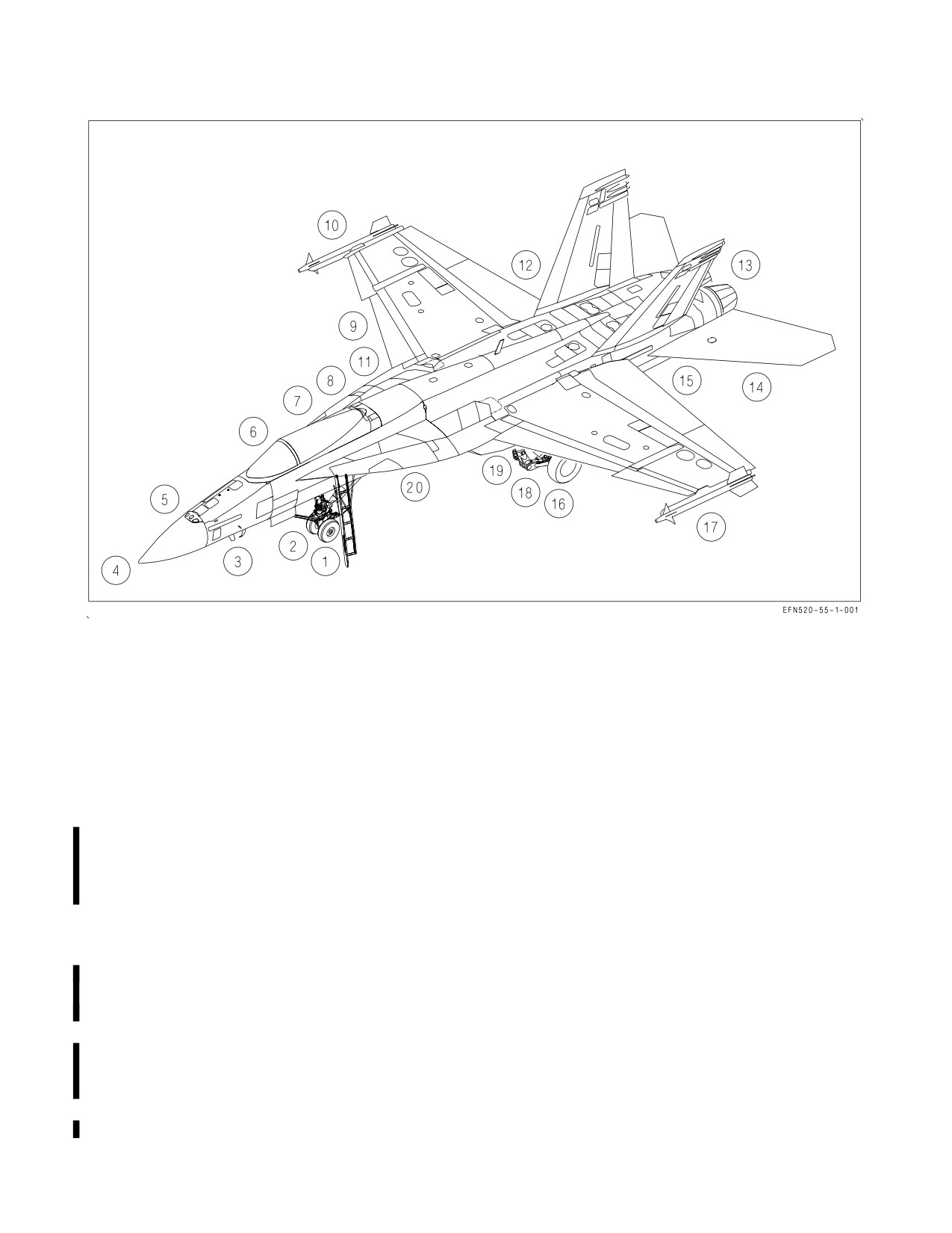
A1-F18EA-NFM-000
Figure 7-1. Exterior Inspection
of the inlet should show no sign of disbonding or peeling. All conductive tape, the windshield aft arch
termination strip, NLG blade seals, canopy and wing conductive bulb seals, and TEF/rudder boots
should be fully bonded, with no loose or peeling corners or edges. It is normally acceptable to trim loose
materials that are noticed just prior to flight.
7.1.3 Exterior Inspection. The exterior inspection (figure 7-1) is divided into 20 areas, beginning at
the left forward fuselage and continuing clockwise around the aircraft. Check doors secure and be alert
for loose fasteners, cracks, dents, leaks, and other general discrepancies. Close inspection shall be given
to the left and right nose sections for moldline defects (bends, dents, dings, cracking or blistering of
exterior coatings, or other surface discrepancies) that will affect the pitot-static system and RVSM
capability.
1. Nose landing gear
a. Drag brace/fairing - CHECK CONDITION
b. Drag brace ground safety pin - REMOVED
c. Holdback fitting - CHECK CONDITION
d. Tires and wheels - CHECK CONDITION
e. Ensure key washer not in direct contact with wheel hub.
III-7-2
ORIGINAL
A1-F18EA-NFM-000
f. Strut piston chrome exposed - 6 INCHES
g. Launch bar - CHECK CONDITION
h. Nosewheel steering assembly - CHECK CONDITION
i. Tiedown rings (2) - CHECK FOLDED AGAINST STRUT
j. Taxi and approach lights - CHECK CONDITION
k. Strut pressure gauges (2) - CHECK IN THE GREEN
l. Retract actuator - CHECK CONDITION
m. Strut - CHECK CONDITION
2.
Nose wheelwell
a. Maintenance code switch - SELECT RESET MOMENTARILY (applies power to the SMS
processor).
b. Doors and linkages - CHECK CONDITION
3.
Nose section (left side)
a. Fuselage surface - CHECK CONDITION (no bends, dents, dings, cracking or blistering of
exterior coatings, or other surface discrepancies)
b. Safety switches - CHECK
(1) Expendables - Yellow when out
(2) Gun electrical - Orange when out
(3) Gun holdback - Orange when out
c. Gun - PREFLIGHT
d. AOA probe - CHECK CONDITION
(1) Smooth, concentric rotation through the full range of travel to include while gently pulling
and pushing the AOA probe.
(2) No bends, dents, dings, cracking or blistering of exterior coatings, or other surface
discrepancies.
e. Pitot tube - CHECK CONDITION (no bends, dents, dings, cracking or blistering of exterior
coatings, or other surface discrepancies).
f. Pitot static drains (4) - CLOSED (underside)
g. Forward antennas - CHECK CONDITION
III-7-3
ORIGINAL
A1-F18EA-NFM-000
(1) Blade antenna (Comm 1, DL, IFF)
(2) Hump antenna (ALR-67 Low band array)
(3) Flush chevron antenna (ICLS, ACLS)
h. Radome - CHECK SECURE (2 points)
4.
Nose section (top)
a. Gun blast diffuser and gun port - CLEAR
5.
Nose section (right side)
a. Fuselage surface - CHECK CONDITION (no bends, dents, dings, cracking or blistering of
exterior coatings, or other surface discrepancies)
b. Radome - CHECK SECURE (2 points)
c. AOA probe - CHECK CONDITION
(1) Smooth, concentric rotation through the full range of travel to include while gently pulling
and pushing the AOA probe.
(2) No bends, dents, dings, cracking or blistering of exterior coatings, or other surface
discrepancies.
d. Pitot tube - CHECK CONDITION (no bends, dents, dings, cracking or blistering of exterior
coatings, or other surface discrepancies).
e. Refuel cap - ON
f. Refuel door (8R) - CLOSED/SECURED
6.
Forward fuselage (right side)
a. Aft blade antenna (Comm 2, TCN) - CHECK CONDITION
b. Flush LEX antenna (ALQ-165 low/high band transmitter) - CHECK CONDITION
c. SMS processor - CHECK WEAPON/FUZE CODES
d. DOOR 13R - CLOSED/SECURED
e. Right engine intake - CLEAR
f. Heat exchanger ram air inlet (top, inside intake) - CLEAR
g. Chaff/flare dispensers
(2)
- PREFLIGHT (ensure chaff/flare buckets or access covers
installed).
7.
External fuel tank(s) - PREFLIGHT
III-7-4
ORIGINAL
A1-F18EA-NFM-000
a. Refuel cap - DOWN, LOCKED, ARROW FORWARD
b. Precheck valve - DOWN, FLUSH
8. Station 7 missile, NFLR, or LDT (if installed) - PREFLIGHT
9. Right main landing gear - CHECK
a. Tire and wheel - CHECK CONDITION
b. Brake wear indicator - EXTENDED (not flush or below flush)
c. Planing link - CHECK CONDITION
d. Strut - CHECK CONDITION
e. Tiedown rings (2) - CHECK SPRING CONDITION
f. Landing gear pin - REMOVED
10. Right wing
a. Flush LEF antenna (ALR-67/ALQ-165 receivers) - CHECK CONDITION
b. LEF - CHECK CONDITION
c. Pylons and external stores - PREFLIGHT
d. Wingfold area - CHECK CONDITION AND VERIFY WINGFOLD PIN REMOVED
e. Position lights - CHECK CONDITION
f. LAU-7 - ENSURE NITROGEN BOTTLE INSTALLED AND DOORS SECURE
g. Wingtip AIM-9 (if installed) - PREFLIGHT
h. Aileron - CHECK CONDITION, FAIRED WITH WINGS FOLDED
If the wings are folded, note the position of the ailerons. If the aileron
locking pins do not restrain the ailerons in the faired position, ensure the
ailerons are moved to a faired or outboard position prior to engine start
to preclude damage to the ailerons and TEFs.
i. TEF - CHECK CONDITION
11. Right main wheelwell
a. Hydraulic filter indicators (delta-Ps) - NOT POPPED
III-7-5
ORIGINAL
A1-F18EA-NFM-000
b. APU accumulator gauge - CHECK (3,000 psi nominal)
c. APU handpump handle - STOWED AND PINNED
d. Doors and linkages - CHECK CONDITION
e. Landing gear downlock and retract actuators - CHECK CONDITION
12. Aft fuselage (right side)
a. Vertical tail and rudder - CHECK CONDITION
b. Strobe light - CHECK CONDITION
c. Fuel vent outlet - CLEAR
d. Light/antenna radomes - CHECK CONDITION
(1) Tail light (top)
(2) ALQ-165 low/high band receiver (middle)
(3) ALR-67 receiver (bottom)
e. Dump outlet - CLEAR
f. Stabilator - CHECK CONDITION
g. Exhaust nozzle and afterburner section - CHECK CONDITION
13. Arresting hook area
a. Arresting hook - CHECK CONDITION (make sure cotter key installed in hook point attach
bolt)
b. Arresting hook pin - REMOVED
c. Towed decoy stand-off bar (when installed) - CHECK CONDITION
14. Aft fuselage (left side)
a. Exhaust nozzle and afterburner section - CHECK CONDITION
b. Stabilator - CHECK CONDITION
c. Vertical tail and rudder - CHECK CONDITION
d. Antenna radomes - CHECK CONDITION
(1) ALQ-165 high band transmitter (top)
(2) ALQ-165 low band transmitter (middle)
III-7-6
ORIGINAL
A1-F18EA-NFM-000
(3) ALR-67 receiver (bottom)
e. Dump outlet - CLEAR
f. Strobe light - CHECK CONDITION
g. Fuel vent outlet - CLEAR
15. Aft fuselage (underside)
a. APU intake (screened) and exhaust ducts - CLEAR
b. ATS exhaust ducts (screened) - CLEAR
c. ALE-50 dispenser - CHECK CONDITION (make sure live or protected magazine installed)
16. Left main wheelwell
a. Hydraulic filter indicators (delta-Ps) - NOT POPPED
b. Doors and linkages - CHECK CONDITION
c. Landing gear downlock and retract actuators - CHECK CONDITION
d. Landing gear pin - REMOVED
17. Left wing
a. TEF - CHECK CONDITION
b. Aileron - CHECK CONDITION, FAIRED WITH WINGS FOLDED
If the wings are folded, note the position of the ailerons. If the aileron
locking pins do not restrain the ailerons in the faired position, ensure the
ailerons are moved to a faired or outboard position prior to engine start
to preclude damage to the ailerons and TEFs.
c. Wingtip AIM-9 (if installed) - PREFLIGHT
d. LAU-7 - ENSURE NITROGEN BOTTLE INSTALLED AND DOORS SECURE
e. Position lights - CHECK CONDITION
f. Wingfold area - CHECK CONDITION AND VERIFY WINGFOLD PIN REMOVED
g. Pylons and external stores - PREFLIGHT
h. LEF - CHECK CONDITION
III-7-7
ORIGINAL
A1-F18EA-NFM-000
i. Flush LEF antenna (ALR-67/ALQ-165 receivers) - CHECK CONDITION
18. Left main landing gear
a. Tire and wheel - CHECK CONDITION
b. Brake wear indicator - EXTENDED (not flush or below flush)
c. Planing link - CHECK CONDITION
d. Strut - CHECK CONDITION
e. Tiedown rings (2) - CHECK SPRING CONDITION
19. Station 5 missile or TFLR (if installed) - PREFLIGHT
20. Forward fuselage (left side)
a. Chaff/flare dispensers
(2)
- PREFLIGHT (ensure chaff/flare buckets or access
covers
installed).
b. Left engine intake - CLEAR
c. Heat exchanger ram air inlet (top, inside intake) - CLEAR
d. Fuel cavity drains (underside) - VERIFY NO LEAKS
e. Loose fasteners - CHECK
f. Flush LEX antenna (ALQ-165 low/high band transmitter) - CHECK CONDITION
7.1.4 Before Entering Cockpit.
1. Ensure all doors forward of the intakes are secured properly.
2. Boarding ladder - SECURE (2 points)
3. Fuselage (upper surface)
a. Spoilers - CHECK CONDITION
b. Upper blade antenna (Comm 1, DL, TCN) - CHECK CONDITION
c. ECS auxiliary duct doors - CHECK DOWN/CONDITION
d. Maintenance handle - CHECK STOWED
4.
(LOTs 21-24) Over-the-shoulder cameras (2) - CHECK SECURE
5. CVRS tapes - INSTALL IN RECORDERS (if desired)
III-7-8
ORIGINAL
A1-F18EA-NFM-000
6. EMI shields (covers over bay behind ejection seat) - CLOSED/SECURED
Ensure the EMI shields are properly closed and secured prior to closing
the canopy to prevent damage to the shields and the canopy actuation
link.
7. Ejection seat SAFE/ARMED handle - SAFE
8. Ejection seat(s) - PREFLIGHT
a. Manual override handle - FULL DOWN and LOCKED
b. Right pitot - STOWED
c. Ballistic gas quick-disconnect - CONNECTED (indicator dowel flush or slightly protruding)
d. Top latch plunger locking indicator - FLUSH WITH THE END OF THE PLUNGER
If the top latch plunger locking indicator is not flush, the seat could come
loose on the mounting rails.
e. Catapult manifold valve - CHECK (hoses and manifold connected; retaining pin installed)
f. Parachute withdrawal line - CONNECTED/SECURED
g. Parachute container lid - SECURE
h. Left pitot - STOWED
i. Electronic sequencer - NOT ACTIVATED
(1) Indicator should be BLACK (not activated).
(2) White - CHECK THERMAL BATTERIES NOT ACTIVATED
j. Thermal batteries - NOT ACTIVATED
(1) Indicator should be WHITE or PINK (not activated).
(2) Black or purple is UNSAT (activated).
k. Console oxygen/comm lines - CONNECTED/SECURED
l. Survival kit - CHECK
(1) Oxygen/comm lines - CONNECTED/SECURED
III-7-9
ORIGINAL
A1-F18EA-NFM-000
(2) Emergency oxygen gauge - IN THE BLACK
(3) Seat pan - CHECK SECURED TO SEAT (pull up on front end to test security)
m. Radio beacon lanyard - SECURED TO COCKPIT FLOOR (make sure lanyard and quick
release connector are positioned forward of the underseat rocket motor tubes)
n. Lap belts - SECURE (pull up strongly on each belt to make sure bolt fittings are engaged in
the seat)
o. Leg restraint lines - CHECK
Check that leg restraint lines are secured to seat and floor and are not twisted. Check that lines
are routed first through the thigh garter ring, then through the lower garter ring, and then
routed outboard of the thigh garter ring before the lock pins are inserted into the seat just
outboard of the snubber boxes.
Failure to route the restraint lines properly through the garters could
cause serious injury during ejection/emergency egress.
p. Ejection seat firing initiators - CHECK FIRING LINKAGE CONNECTED TO SEARS
q. Parachute risers - CHECK (ensure risers are routed down the forward face of the parachute
container and are routed behind the retaining strap; pull on risers to check ease of operation).
r. SEAWARS - CHECK FOR PROPER INSTALLATION
s.
(SJU-17A (V)1/A, 2/A, and 9/A) Backpad adjustment handle - SET TO DESIRED POSITION
For solo flight in the F/A-18F -
9. Rear cockpit - SECURE
a. Ejection seat SAFE/ARMED handle - SAFE
b. Ejection control handle pin - VERIFY REMOVED
c.
(LOTs 21-24) EMERG BRK handle - STOWED
The position of the EMERG BRK handle is the only indication that
emergency braking is selected; no warning or caution is displayed. The
EMERG BRK handle(s) must be fully stowed in both cockpits to ensure
that normal braking with anti-skid is available.
d. CANOPY JETT handle - OUTBOARD AND DOWN/PIN REMOVED
e. L(R) DDI and MPCD knobs - OFF
III-7-10
ORIGINAL
A1-F18EA-NFM-000
f. Comm 1 and 2 knobs - OFF
g. EJECTION MODE handle - SOLO/COLLAR INSTALLED
h. SEAT CAUT MODE switch - SOLO/PIN INSTALLED
i. Leg restraints, lap belts, parachute risers, JHMCS QDC - SECURED/STOWED
j. Loose items - SECURED
In trainer configured aircraft -
k. Control stick - CHECK SECURE
l. UFCD adapter - VERIFY NOT INSTALLED
Forward stick throw is restricted if a rear cockpit control stick and UFCD
adapter are both installed.
m. Throttles - CHECK CONDITION
7.1.5 Interior Checks - Pilot.
Do not place any item on the glare shield, as scratching the windshield is
probable.
1. Leads, leg restraints, and harness - SECURE/ADJUST
Connect oxygen, g suit, QDC (if applicable) and communications leads. Check routing of JHMCS.
UHVI does not interfere with oxygen hose. Check QDC is securely connected or stowed if not in use.
Fasten and secure leg restraint garters and lines. Check leg garters buckled and properly adjusted
with hardware on inboard side of the legs. Connect and adjust lap belt straps. Attach parachute
Koch fittings to harness buckles. Check operation of shoulder harness locking mechanism.
The leg restraint lines must be buckled at all times during flight to ensure
that the legs will be pulled back upon ejection. This enhances seat
stability and prevents leg injury by keeping the legs from flailing
following ejection.
III-7-11
ORIGINAL
A1-F18EA-NFM-000
The JHMCS UHVI must be properly routed through the torso bundle
flue under the survival vest and the QDC secured in the QMB to ensure
that no entanglement exists with the oxygen hose. Misrouting of the
JHMCS UHVI may allow the QDC to rub against the oxygen hose
disconnect causing unintentional oxygen/communications disconnect in
flight.
2. Ejection control handle - CLEAR
3. Ejection control handle pin - VERIFY REMOVED
Left console -
1. Circuit breakers - IN
2. Manual canopy handle - STOWED
3. MC and HYD ISOL switches - NORM
4. OBOGS control switch - OFF
5. OXY FLOW knob - OFF
6. OBOGS monitor pneumatic BIT plunger - VERIFY UNLOCKED AND FULLY EXTENDED
Inadvertent rotation of the OBOGS monitor pneumatic BIT plunger
while pressed can result in the locking of the plunger in a maintenance
position and may result in intermittent OBOGS DEGD cautions and lead
to hypoxia. Rotation of the BIT plunger disengages the locking slot
allowing the plunger to extend and move freely when pushed.
7. COMM 1/IFF ANT SEL switches - AUTO/BOTH
8. COMM panel - SET
a. RLY and GXMT switches - OFF
b. ILS CHANNEL/ILS switch - SET/UFCD
c. CRYPTO, MODE 4, (IFF) MASTER switches - NORM/OFF/NORM
9. VOL panel - SET AS DESIRED
10. FCS GAIN switch - NORM/GUARD DOWN
11. APU switch - OFF
III-7-12
ORIGINAL
A1-F18EA-NFM-000
12. PROBE switch - RETRACT
13. EXT TANKS switches - NORM
14. DUMP switch - OFF
15. INTR WING switch - NORM
16. GEN TIE CONTROL switch - NORM/GUARD DOWN
17. EXT LT panel - SET
a. EXT LT IDENT knob - NORM
b. FORM knob - AS REQUIRED
c. POS knob - AS REQUIRED
d. STRB switch - BRT/DIM/OFF (as required)
18. Throttles - OFF
19. External lights master switch - FORWARD
20. BRK PRESS switch - CHECK (2,600 psi min)
Instrument panel -
1. PARK BRK handle - SET
2. LDG/TAXI LIGHT switch - OFF
3. ANTI SKID switch - ON
4. SELECT JETT knob - SAFE
5. FLAP switch - FULL
6. LAUNCH BAR switch - RETRACT
7. LDG GEAR handle - DN
8. Landing gear handle mechanical stop - FULLY ENGAGED
9. CANOPY JETT handle - FORWARD
10. MASTER ARM switch - SAFE
11. EMERG JETT button - NOT PRESSED IN
III-7-13
ORIGINAL
A1-F18EA-NFM-000
12. FIRE and APU FIRE warning lights - NOT PRESSED IN
NOTE
If a FIRE light is depressed, approximately 1/8 inch of yellow and
black stripes will be visible around the outer edges of the light.
13. L(R) DDI, HUD, and MPCD knobs - OFF
NOTE
Power to the UFCD is controlled by the MPCD knob, so the UFCD
knob does not need to be OFF.
14. COMM 1 and 2 knobs - OFF
15. CVRS mode switch - OFF
16. ALT switch - BARO or RDR
17. ATT switch - AUTO
18. Standby attitude reference indicator - CAGED
19. IR COOL switch - OFF
20. SPIN switch - NORM/GUARD DOWN
21. HOOK handle - UP
22. WINGFOLD switch - SAME AS WING POSITION
23. AV COOL switch - NORM
Pedestal Panel (LOTs 23 and up) -
1. ECM JETT button - NOT PUSHED IN
2. JAMMER switch - OFF
3. RWR switch - OFF
4. DISPENSER switch - OFF
5. AUX REL switch - NORM
6. RUD PED ADJ lever -
a. SET PEDAL POSITION FULL FORWARD
D Cycle left and right pedal to check for binding.
III-7-14
ORIGINAL
A1-F18EA-NFM-000
b. SET PEDAL POSITION AS DESIRED FOR FLIGHT
D Locks securely when RUD PED ADJ lever released.
Restrain the rudder pedals during adjustment. Unrestrained release of
the rudder pedals may damage the rudder pedal mechanism.
Ensure the rudder pedals are locked in position after adjustment. Failure
to lock the rudder pedals may result in uncommanded forward rudder
pedal movement inflight.
Pedestal Panel (LOTs 21 - 22) -
1. ECM JETT button - NOT PUSHED IN
2. DISPENSER switch - OFF
3. ECM knob - OFF
4. DECOY switch - OFF
5. AUX REL switch - NORM
6. RWR switch - OFF
7. Clock - CHECK AND SET
8. RUD PED ADJ lever -
a. SET PEDAL POSITION FULL FORWARD
D Cycle left and right pedal to check for binding.
b. SET PEDAL POSITION AS DESIRED FOR FLIGHT
D Locks securely when RUD PED ADJ lever released.
Right console -
1. Circuit breakers - IN
2. GEN switches - NORM
3. BATT switch - OFF
4. ECS panel - SET
a. MODE switch - AUTO
III-7-15
ORIGINAL
A1-F18EA-NFM-000
Selection of MAN with the ECS mode switch is prohibited. Selecting
MAN while the aft cooling fan shutoff valve is open may cause the fan to
overspeed resulting in a catastrophic fan failure potentially leading to loss
of OBOGS.
b. CABIN TEMP knob - AS DESIRED
c. CABIN PRESS switch - NORM
d. BLEED AIR knob - OFF
e. ENG ANTI ICE switch - OFF
f. PITOT ANTI ICE switch - AUTO
5.
DEFOG handle - MID RANGE
6.
WINDSHIELD switch - OFF
7.
INTR LT panel - SET
a. CONSOLES, INST PNL, and FLOOD knobs - AS DESIRED
b. CHART and WARN/CAUT knobs - AS DESIRED
c. MODE switch - DAY, NITE, or NVG (as required)
8.
Sensor control panel - SET
a. FLIR, LTD/R, and LST/NFLR switches - OFF/SAFE/OFF
b. INS and RADAR knobs - OFF
9.
NVG storage container - CHECK SECURE
7.1.6 Interior Checks - WSO.
1. Leads, leg restraints, and harness - SECURE/ADJUST
Connect oxygen, g suit, QDC (if applicable) and communications leads. Check routing of JHMCS
UHVI does not interfere with oxygen hose. Check QDC is securely connected or stowed if not in use.
Fasten and secure leg restraint garters and lines. Check leg garters buckled and properly adjusted
with hardware on inboard side of the legs. Connect and adjust lap belt straps. Attach parachute
Koch fittings to harness buckles. Check operation of shoulder harness locking mechanism.
III-7-16
ORIGINAL
A1-F18EA-NFM-000
• The leg restraint lines must be buckled at all times during flight to
ensure that the legs will be pulled back upon ejection. This enhances
seat stability and prevents leg injury by keeping the legs from flailing
following ejection.
• The JHMCS UHVI must be properly routed through the torso bundle
flue under the survival vest and the QDC secured in the QMB to
ensure that no entanglement exists with the oxygen hose. Misrouting
of the JHMCS UHVI may allow the QDC to rub against the oxygen
hose disconnect causing unintentional oxygen/communications dis-
connect in-flight.
2. Ejection control handle - CLEAR
3. Ejection control handle pin - VERIFY REMOVED
In trainer configured aircraft -
1. Control stick - CHECK SECURE
2. UFCD adapter - VERIFY NOT INSTALLED
Forward stick throw is restricted if a rear cockpit control stick and UFCD
adapter are both installed.
3. Throttles - CHECK CONDITION
4. RUD PED ADJ lever - ADJUST PEDAL POSITION
Left console -
1. OXY FLOW knob - OFF
2. Left hand controller - CHECK SECURE
3. CANOPY JETT handle - OUTBOARD AND DOWN
4. VOL panel - SET AS DESIRED
5. RECCE panel - SET
a. POD PWR knob - OFF
b. ATARS switch - OFF
III-7-17
ORIGINAL
A1-F18EA-NFM-000
Instrument panel -
1.
(LOTs 21-24) EMERG LDG GEAR handle - STOWED
2.
(LOTs 21-24) EMERG BRK handle - STOWED
The position of the EMERG BRK handle is the only indication that
emergency braking is selected: no warning or caution is displayed. The
EMERG BRK handle(s) must be fully stowed in both cockpits to ensure
that normal braking with anti-skid is available.
Due to friction in the EMERG BRK handle mechanism, the handle may
not return to the fully stowed position unless positively pushed.
3. L(R) DDI and MPCD knobs - OFF
NOTE
Power to the UFCD is controlled by the MPCD knob, so the UFCD
knob does not need to be OFF.
4. EMERG JETT button − NOT PRESSED IN
5. COMM 1 and 2 knobs - OFF
6. Standby attitude reference indicator - CAGED
7. EJECTION MODE handle - NORM
Right console -
1. Right hand controller - CHECK SECURE
2. INTR LT panel - SET
a. CONSOLES, INST PNL, and FLOOD knobs - AS DESIRED
b. CHART and WARN/CAUT knobs - AS DESIRED
3. NVG storage container - CHECK SECURE
7.2 ENGINE START
A self-contained (battery/APU) start is the primary method for starting the engines. The aircraft
also has provisions for starting on external power, external air, or opposite engine bleed air (crossbleed)
for circumstances when that may be appropriate (e.g., alert launch, low battery, maintenance, engine
restart after APU shutdown, etc.). As such, the steps for a ″normal″ battery/APU start are numbered
below, while steps for alternate starting sources are lettered.
III-7-18
ORIGINAL
A1-F18EA-NFM-000
With an external power start, all electrical systems are operative. With a battery start, power is
available to operate the APU and engine fire warning systems, the caution lights panel, the intercom
system between the aircrew and the ground crew, the cockpit utility light, and the EFD backup display.
The right engine is normally started first in order to provide normal hydraulics to the brakes. During
first engine battery start, the EFD RPM indication typically jumps from 0 to 5 or 10%, and light-off
is indicated by TEMP rising from a minimum reported value of approximately 190°C. When the
corresponding generator comes online (approximately 60%N2 rpm), the engine crank switch returns to
OFF. After both generators are online, the APU will run for 1 minute and then shut down
automatically.
• To prevent engine damage during start, if an engine was not idled
(75% N2 rpm or less) for 5 minutes prior to shutdown and a restart
must be made between 15 minutes and 4 hours after shutdown, the
engine must be motored for 1 minute at 29%N2 or greater before
restart.
• To prevent vibration and damage to compressor blades, do not allow
N2 rpm to dwell between 26 to 29%during engine motoring.
7.2.1 Intercockpit Communications (F/A-18F). The following Challenge/Response voice communi-
cations are mandatory:
Challenge
Response
Pilot - ICS check
WSO - Loud and clear
Pilot - Fire warning
WSO - Roger (Optional)
Pilot - Starting APU left/right
WSO - Roger (Optional)
WSO - Good waypoint zero
Pilot - Roger (Optional)
Pilot - Canopy
WSO - Clear/standby
7.2.2 Engine Start Checks. In the F/A-18F, the WSO must monitor pilot procedures, EFD indica-
tions, and plane captain signals to ensure maximum safety during engine start.
1. BATT switch - ON
III-7-19
ORIGINAL
A1-F18EA-NFM-000
2. Battery gauge - CHECK
NOTE
Nominal voltage for a ″good″ battery should be 23 to 24 vdc. Minimum
battery voltage is that which provides a successful engine start (i.e.,
APU remains online and the EFD remains powered to provide
indications of RPM and TEMP). EFD blanking and/or uncommanded
APU shutdown should be anticipated with a battery voltage at or
below approximately
18
vdc. If a weak battery results in an
unsuccessful engine start attempt, the battery should be charged or
replaced prior to takeoff, since the battery provides the last source of
electrical redundancy for the FCCs.
3. Caution Lights Panel - CHECK CABIN light on (if CPWS installed)
4. ICS - CHECK
With external electrical power -
a. EXT PWR switch - RESET
b. GND PWR switches 1, 2, 3, and 4 - B ON (hold for 3 seconds)
c. L(R) DDI, HUD, and MPCD knobs - ON (both cockpits)
d. COMM 1 and 2 knobs - ON/VOLUME AS DESIRED (both cockpits)
e. LT TEST switch - TEST (both cockpits)
f. MPCD/UFCD - ENTER DESIRED WAYPOINTS
All starts -
5. FIRE warning test - PERFORM
a. FIRE test switch - TEST A (hold until all lights and aural warnings indicate test has been
successfully passed)
b. FIRE test switch - NORM (pause 7 seconds or cycle BATT switch for system reset)
c. FIRE test switch - TEST B (hold until all lights and aural warnings indicate test has been
successfully passed)
NOTE
During a successful FIRE warning test, ALL of the following lights
should illuminate in each TEST position: both FIRE lights
(all
4
bulbs), the APU FIRE light (all 4 bulbs), and both L and R BLEED
warning lights. Additionally, the following voice aural warnings should
be heard in order: ″Engine fire left, engine fire right, APU fire, bleed
air left, bleed air right″ (each repeated twice).
III-7-20
ORIGINAL
A1-F18EA-NFM-000
NOTE
• A complete FIRE warning test is performed in each TEST position
because it is difficult to recognize a single unlit bulb in a FIRE light.
Since an aural warning does not annunciate if any of the FIRE or
BALD loops are bad, lack of an aural warning is the best cue to the
aircrew of a test failure.
• Failure to pause in NORM for at least 3 seconds between TEST A and
TEST B results in a false BALD failure MSP code.
6. Forward MPCD and UFCD knobs - ON
NOTE
Forward MPCD and UFCD need to be turned on to display the
backup HUD format and L/R ATS cautions.
If APU start -
7. APU ACC caution light - VERIFY OFF
8. APU switch - ON (READY light within 30 seconds)
To prevent an APU running engagement and to prevent APU exhaust
torching, a minimum of 2 minutes must elapse between APU shutdown
and another APU start.
NOTE
If an APU fire or overheat condition is detected on the ground, the
APU fire extinguishing system will automatically shutdown the APU
and, after 10 seconds, will discharge the extinguisher bottle.
If external air start -
a. BLEED AIR knob - OFF
All starts -
Regardless of the engine start air source utilized, the corresponding GEN
switch should be ON, as the generator provides primary overspeed cutout
protection for the ATS.
9. ENG CRANK switch - R
III-7-21
ORIGINAL
A1-F18EA-NFM-000
10. Right throttle - IDLE (10% N
2 minimum. Oil pressure should be a minimum of 10 psi within 30
seconds. Maximum transient EGT during start is 871°C).
NOTE
During ground starts only, the FADEC will automatically cut back fuel
flow to prevent EGT from exceeding 815°C. If required, fuel flow will
be reduced to the point of engine flameout. While this mechanization
is provided to prevent engine damage due to an overtemp, the aircrew
should not rely on it to prevent a hot start.
11. CFIT voice warnings - CHECK (OFP 18E: ″ROLL-LEFT...ROLL-LEFT″) (OFP 13E: ″ROLL-
OUT...ROLL-OUT″)
NOTE
MC1 does an ACI configuration check after the generator comes on
line during a cold start power-up by commanding the above voice
warning. If the ACI does not contain the appropriate software, the
″ROLL-LEFT...ROLL-LEFT″ voice warning is not heard and the MC1
will assume an incompatible ACI is installed in the aircraft, GPWS/
TAWS voice warnings are not available and only the recovery arrow
will be displayed during a CFIT condition.
12. Battery gauge - VERIFY 28 vdc
NOTE
If the battery gauge fails to reach approximately
28 vdc with one
generator online, a battery charger malfunction has occurred which
requires maintenance action prior to flight.
13. L(R) DDI, HUD, and MPCD knobs - ON (both cockpits)
During a battery start of the right engine, recognition of a R ATS caution
will be delayed until the displays are turned on. Once the displays are
powered, verify that the R ATS caution is not set.
14. HMD switch (if applicable) - ON
15. EFD - CHECK
III-7-22
ORIGINAL
A1-F18EA-NFM-000
Ground idle -
RPM
61% minimum
TEMP
250° to 590°C
FF
600 to 900 pph
OIL
35 to 90 psi (warm oil)
NOZ
77% to 83%
NOTE
Following the initial start of each engine, engine anti-ice airflow will
turn on automatically 45 seconds after the engine reaches idle power
and will remain on for 30 seconds, provided the throttle remains at
IDLE. The corresponding LHEAT or RHEAT advisory will be
displayed during this engine anti-ice functional test.
If external power start -
a. External electrical power - DISCONNECT
If APU or crossbleed start -
16. BLEED AIR knob - NORM
NOTE
The bleed air shutoff valves close during the fire warning test, so the
BLEED AIR knob must be rotated from OFF to NORM with ac power
applied to reset the valves.
17. LT TEST switch - TEST (both cockpits)
For a crossbleed start ensure the APU switch is OFF. The operating engine should be advanced
to a minimum of 80% N2.
18. ENG CRANK switch - L
19. Left throttle - IDLE (10%N2 minimum)
20. ENG CRANK switch - CHECK OFF
21. EFD - CHECK
If external air start -
a. BLEED AIR knob - NORM
7.3 BEFORE TAXI CHECKS
1. WYPT 0 and MVAR - CHECK/SET
2. GPWS/TAWS - CHECK BOXED
3. INS knob - CV or GND (PARK BRK SET)
III-7-23
ORIGINAL
A1-F18EA-NFM-000
4. RADAR knob - OPR
5. FLIR and LST/FLR switches - AS DESIRED
6. UFCD avionics - TURN ON
a. RALT - ON/SET
b. TCN - ON, T/R, CH SET
c. IFF - ON/MODES UNBOXED
7. WINGFOLD switch - SPREAD
8. FCS RESET button - PUSH (verify RSET advisory displayed)
NOTE
Prior to takeoff
(cycle to WoffW), a successful FCS RESET
automatically clears all BLIN codes.
If no reset (RSET advisory displayed) -
a. FCS exerciser mode - INITIATE (push the FCS RESET button while holding the FCS BIT
consent switch up)
In standard or warm conditions, do not initiate the FCS exerciser mode
multiple times in an attempt to get a successful FCS RESET. In such
conditions, multiple initiations may excessively elevate hydraulic system
temperatures, increasing actuator and hydraulic pump seal wear and
potentially decreasing component life.
b. FCS RESET button - PUSH (verify RSET advisory displayed)
After successful FCS reset -
9. FLAP switch - AUTO
10. FCS IBIT - PERFORM
a. FCS BIT consent switch - HOLD UP THEN PRESS THE FCS OPTION
b. AOA warning tone - VERIFY ANNUNCIATION AT FCS IBIT COMPLETION
c. FCS A and FCS B BIT status - VERIFY GO
d. FCS display - VERIFY NO BLIN CODES
III-7-24
ORIGINAL
A1-F18EA-NFM-000
Flight with BLIN codes could result in a FCS failure and aircraft loss.
Pressing the FCS RESET button simultaneously with the paddle switch
does not correct BIT detected FCS failures; it simply clears the BLIN
codes from the FCS display. FCS IBIT must be re-run after clearing
BLIN codes to ensure that previously detected failures no longer exist. If
BLIN codes remain following IBIT, maintenance action is required to
identify and correct failures in the FCS.
NOTE
• With the wings folded, both ailerons are X’d out, but no aileron BLIN
codes should be displayed. Even with wings folded, there are aileron
functions tested that may reveal FCS failures via valid BLIN codes.
• For FCS IBIT to start, the FCS BIT consent switch must be held for
at least 2 seconds. If not held for the required time, FCS A and FCS B
will indicate RESTRT on the BIT status line. If RESTRT is dis-
played, select STOP on the FCS-MC sublevel display and then repeat
the initiation procedure.
• The FCS will not enter IBIT if the throttles are above 14° THA or
NWS is engaged.
• Do not operate any FCS related switches or move the stick or rudder
pedals while FCS IBIT is running, as this may produce false failure
indications.
• With the wings folded, a BIT status indication of GO will only be
displayed for approximately 2 seconds before reverting to a DEGD
indication. BIT status will return to GO when the wings are spread and
locked.
• If the FCS IBIT fails, FCS A and FCS B will indicate DEGD on the
BIT status line. Note surface X’s and/or BLIN codes and contact
maintenance personnel.
11.
Trim - CHECK (check pitch, roll, and yaw trim for proper movement in all directions)
NOTE
It is not possible to trim the stabilators to negative values (TED) with
WonW.
III-7-25
ORIGINAL
A1-F18EA-NFM-000
12. T/O TRIM button - PRESS UNTIL TRIM ADVISORY DISPLAYED (stabilators 4° NU)
NOTE
If the TRIM advisory does not appear, longitudinal trim is not set for
takeoff. The CHECK TRIM caution will be displayed when both
throttles are advanced beyond 27° THA if the stabilators are trimmed
less than 3.5° TEU with the launch bar up (field takeoff) or 6.5° TEU
with the launch bar down (carrier takeoff).
13. Controls - CHECK (tolerance ±1°)
a. Control stick - CYCLE
(1) Full aft
- CHECK 24° NU STABILATOR (check left and right stabilators
track symmetrically within ±1° of each other)
At certain ejection seat heights, the A/A weapon select switch may hook
the EJECTION handle at the full aft stick deflection. With an armed
seat, inadvertent ejection initiation may occur if the stick returns to a
neutral position.
(2) Full fwd - CHECK 20° ND STABILATOR (check left and right stabilators
track symmetrically within ± 1° of each other)
(3) Full L/R - CHECK 30° DIFFERENTIAL STABILATOR (21° with tanks or A/G stores on
any wing station)
- CHECK DIFFERENTIAL TEFs
b. FLAP switch - HALF
c. Rudder pedals - CYCLE RUDDERS 40° L/R
d. FLAP switch - FULL (carrier-based)
e. TRIM - SET FOR CATAPULT LAUNCH (carrier-based)
14. PROBE, speedbrake, LAUNCH BAR switches and HOOK handle - CYCLE (LAUNCH BAR
optional for shore based operations.)
Ensure HOOK handle is fully up to minimize the probability of inadvertent hook drops during
catapult launch.
15. Pitot and AOA heat check - PERFORM
a. PITOT ANTI ICE switch - ON
III-7-26
ORIGINAL
A1-F18EA-NFM-000
b. Make sure ground crew verify proper operation
c. PITOT ANTI ICE switch - AUTO
Failure of both AOA probe heaters in icing conditions may cause a sharp
uncommanded nose down attitude, uncontrollable by normal stick forces
or paddle switch actuation.
16. AV COOL switch emergency check (if ground personnel present)
a. AV COOL switch - EMERG then release
b. Make sure ground crew verify proper operation and stows emergency scoop.
17. APU - VERIFY OFF
18. FLBIT option - SELECT
19. BINGO - CHECK/SET
20. CVRS - AS DESIRED (both cockpits)
21. Standby attitude reference indicator - UNCAGE AND ERECT (both cockpits)
22. Altimeter setting - SET (both cockpits)
a. Altimeter setting displayed on HUD.
b. HUD altitude displayed within ±30 feet of parking spot elevation.
c. Standby altimeter within ±60 feet of parking spot elevation.
NOTE
If the standby altimeter barometric pressure is adjusted during the
FCS IBIT, the altitude reading displayed in the HUD will not change
until the IBIT is complete.
23. INS - CHECK
a. Alignment status - VERIFY COMPLETE
b. GPS HERR/VERR - VERIFY WITHIN LIMITS
c. INS knob - NAV or IFA
III-7-27
ORIGINAL
A1-F18EA-NFM-000
NOTE
• Prior to placing the INS switch to IFA for a GPS alignment or for
AINS position keeping, ensure valid GPS data is available. AINS
position keeping is normally available when GPS HERR and VERR
are each less than 230 feet. Double digit GPS HERR/VERR (less than
100 feet) should guarantee AINS position keeping is available.
• Selecting IFA without good GPS data and without a complete carrier
or ground alignment will cause the INS to attempt to perform a radar
IFA and will halt/prevent alignment. If this occurs, return the INS
knob to GND or CV (as appropriate).
d. Verify HUD airspeed indicates less than 50 kts.
24.
MUMI/ID - SELECT/ENTER DATE and FLT
25.
Stores page - VERIFY PROPER STORE INVENTORY AND STATION STATUS
26.
ZTOD/LTOD - BOX TO ENABLE HUD DISPLAY (if desired)
NOTE
• The TIMEUFC option is removed from the HSI format if INS
alignment is being performed (GND, CV, or IFA GPS).
• At GPS power up (first GEN online), SDC time and date are
automatically sent to the GPS to aid the acquisition of satellites. After
satellite acquisition, the GPS backloads satellite time to the SDC thus
synchronizing the SDC with precise GPS time. This GPS time
backload is only performed once per flight after the initial MC1 power
up.
• Manually changing ZTOD, LTOD, or the DATE with WonW resets
SDC time and/or date and reinitializes the GPS (even if GPS had a
good satellite acquisition). GPS reinitialization will delay the avail-
ability of AINS position keeping. GPS time synchronization will not be
available until a subsequent MC1 power-up (cold start). ARC-210
radios will need to be re-synched to enable HAVE QUICK operations.
27.
Weapons/sensors - ON/BIT CHECK (as required)
28.
BIT page - NOTE DEGD/FAIL INDICATIONS
III-7-28
ORIGINAL