F18. FLIGHT MANUAL (2008) - page 19
A1-F18EA-NFM-000
2.14 OXYGEN SYSTEMS
2.14.1 On Board Oxygen Generating System (OBOGS). OBOGS provides oxygen rich breathing gas
to the aircrew while either engine is operating. Engine bleed air is cooled and routed through the
OBOGS inlet air shutoff valve to the OBOGS concentrator. The breathing gas is routed from the
concentrator to a cockpit plenum, where the temperature is stabilized and a limited supply is stored for
peak flow demands. From the plenum, the breathing gas flows through the pilot services panel oxygen
disconnect, through the seat survival kit, to the aircrew regulators and masks.
A leak or break in the breathing gas system anywhere from the pilot
services panel oxygen disconnect to the mask will prevent either normal
OBOGS breathing gas or emergency oxygen from being delivered to the
mask in its intended concentration. Leaks and breaks may be difficult to
locate and/or verify. If hypoxic symptoms are experienced or an OBOGS
system degrade occurs, immediate descent below
10,000
feet cabin
altitude is required to prevent severe or incapacitating hypoxia.
The OBOGS concentrator is powered by the left 115 volt ac bus. Two molecular sieve beds in the
OBOGS concentrator remove most of the nitrogen from the engine bleed air. The nitrogen is dumped
overboard while the remaining output of oxygen rich breathing gas is supplied to the aircrew.
2.14.1.1 OBOGS Monitor. The CRU-99/A solid state oxygen monitor is located on the left side of the
seat bulkhead in the front cockpit and is powered by the left 28 volt dc bus. The monitor continuously
measures oxygen concentration in the OBOGS breathing gas and provides a discrete signal to activate
the OBOGS DEGD caution if the oxygen concentration falls below a predetermined level.
Loss of electrical power to the OBOGS monitor prevents reporting of
OBOGS DEGD conditions.
The monitor performs a power-up BIT during a 2 minute warm-up period and conducts a periodic
BIT every 60 seconds. No indication is provided if power-up or periodic BIT pass.
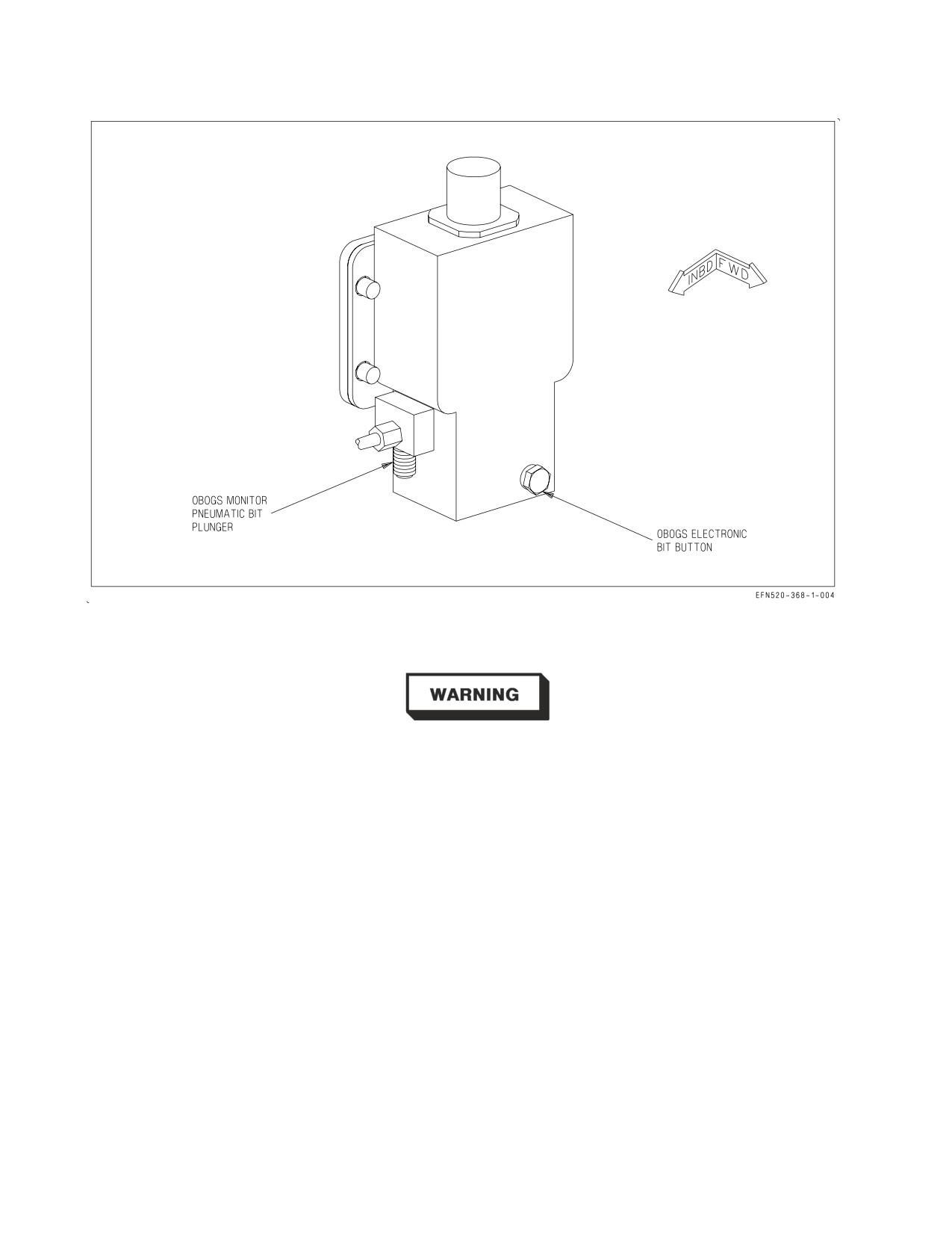
Preflight BIT of the monitor is accomplished by using either the pneumatic BIT plunger or the
electronic BIT pushbutton. Refer to figure 2-33. Pressing up and holding the pneumatic BIT plunger
for 15 to 65 seconds tests the operation of the OBOGS monitor by diverting cabin air into the monitor
to create a low oxygen concentration condition.
After initiating OBOGS pneumatic BIT, failure to ensure plunger is fully
extended may result in contamination of OBOGS plenum which may lead
to hypoxic conditions.
Momentarily pressing and releasing the electronic BIT pushbutton tests the monitor electronically.
Successful completion of either test activates the OBOGS DEGD caution, which clears automatically
I-2-107
ORIGINAL
A1-F18EA-NFM-000
Figure 2-33. OBOGS Monitor
after BIT is complete and OBOGS resets to normal operation.
Successful OBOGS monitor BIT is required prior to flight. A BIT failure
indicates that there is no protection against inadequate oxygen concen-
tration or hypoxia due to a degraded OBOGS monitor. Good breathing
gas flow alone does not ensure adequate oxygen concentration.
2.14.1.1.1 OBOGS DEGD Caution. An OBOGS DEGD caution is set by the OBOGS monitor when
oxygen concentration is below a predetermined level. The OBOGS DEGD caution threshold is always
above cabin air conditions, in order to provide a physiological safety margin.
NOTE
Oxygen concentration may drop below the predetermined OBOGS
DEGD level if breathing gas flow is unlimited. Removing the mask
without placing the OXY flow knob to OFF, system leaks, and/or loose
aircrew hose connections can overwhelm system capacity and may
result in an OBOGS DEGD caution.
After a total loss of bleed air, OBOGS breathing gas flow will be available until the residual gas
within the system is depleted. The residual oxygen concentration may be sufficient to keep the OBOGS
I-2-108
ORIGINAL
A1-F18EA-NFM-000
DEGD caution from illuminating, but loss of system pressure will ultimately lead to inadequate
pressure and an abrupt inability to breathe.
Low mask flow or increased breathing resistance may occur without an accompanying OBOGS
DEGD caution, which indicates a potential system degradation that may result in oxygen levels below
physiological requirements.
When cabin altitude is above 10,000
feet, OBOGS DEGD caution
procedures shall be executed for low mask flow, increased breathing
resistance, or OBOGS DEGD cautions of any duration.
A single brief appearance of the OBOGS DEGD caution immediately following placing the OBOGS
control switch to ON, turning the OXY FLOW knob to ON, or after donning or removing the mask is
normal. Certain malfunctions affecting the OBOGS system also may momentarily cause OBOGS
DEGD cautions. A momentary OBOGS DEGD caution may clear from the DDI so rapidly that the
aircrew may be unable to determine the cause of the MASTER CAUTION light/tone.
Repeated unexplained MASTER CAUTION lights/tones may be an
indication of OBOGS system degradation.
Even with the OBOGS DEGD caution displayed, OBOGS breathing gas under normal flow is of
higher quality (i.e., oxygen concentration, partial pressure and purity) than cabin air. Once cabin
altitude is below 10,000 feet, aircrew may elect to conserve emergency oxygen by resetting the
emergency oxygen release tab, then either removing the mask and breathing cabin air, or returning the
OXY FLOW knob and the OBOGS control switch to ON and breathing through the mask.
Pure oxygen accelerates recovery from hypoxia. Emergency oxygen shall
be used whenever hypoxic symptoms are recognized.
2.14.1.2 Breathing Regulator. The aircrew torso mounted breathing regulator reduces both normal
and emergency oxygen system operating pressures to breathing pressure levels. The regulator delivers
undiluted OBOGS breathing gas or emergency oxygen to the aircrew at positive pressure, the limits of
which increase automatically with altitude. It interfaces with the hose assembly, which connects with
the seat survival kit oxygen disconnect.
I-2-109
ORIGINAL
A1-F18EA-NFM-000
2.14.1.3 OBOGS Control Switch. The OBOGS control switch, located on the left console in the front
cockpit, is used to control electrical power to the OBOGS concentrator and the OBOGS inlet air shutoff
valve.
ON Supplies electrical power and engine bleed air to the OBOGS concentrator.
OFF OBOGS system off.
2.14.1.4 OXY FLOW Knob. The OXY FLOW knob, located on the left console in both cockpits, is
used to control the supply of OBOGS breathing gas to each aircrew’s mask.
ON OBOGS flow supplied to the mask.
OFF OBOGS flow secured.
It is possible to place the OXY FLOW knob in an intermediate posi-
tion between the ON and OFF detents, which may result in a reduced
flow of breathing gas. The OXY FLOW knob should always be fully
rotated to the ON or OFF detent position.
2.14.2 Emergency Oxygen. Emergency gaseous oxygen is contained in a bottle in the seat survival
kit. The bottle is connected into the OBOGS supply hose as it passes through the kit. From this point,
the emergency oxygen and OBOGS breathing gas share a common path to the aircrew mask.
A leak or break in the breathing gas system anywhere from the pilot
services panel oxygen disconnect to the mask will prevent either normal
OBOGS breathing gas or emergency oxygen from being delivered to the
mask in its intended concentration. Leaks and breaks may be difficult to
locate and/or verify. If hypoxic symptoms are experienced or an OBOGS
system degrade occurs, immediate descent below
10,000
feet cabin
altitude is required to prevent severe or incapacitating hypoxia.
A pressure gauge is visible on the inside left front of the survival kit. The bottle provides
approximately 10−20 minutes of oxygen. Oxygen duration decreases with lower altitude.
Under less than optimum conditions (low altitude, heavy breathing,
loose−fitting mask, etc.), as few as 3 minutes of emergency oxygen may be
available.
I-2-110
ORIGINAL
A1-F18EA-NFM-000
The emergency oxygen supply is activated automatically upon ejection. The emergency oxygen
supply may be activated manually by pulling the emergency oxygen green ring on the outside of the left
thigh. The emergency oxygen supply may be deactivated at aircrew discretion by pushing down on the
release tab immediately forward of the green ring.
With emergency oxygen selected, the OXY FLOW knob(s) shall be
placed to OFF. If not secured, OBOGS system pressure may prevent
emergency oxygen from reaching the breathing regulator. Additionally,
the OBOGS control switch should be placed to OFF to backup the OXY
FLOW knob.
2.15 FIRE DETECTION, FIRE EXTINGUISHING, AND BLEED AIR LEAK DETECTION SYSTEMS
The fire detection system contains dual-loop fire detectors and three FIRE warning lights. The fire
extinguishing system contains a READY/DISCH light and a fire extinguisher bottle. The two systems
provide engine bay, AMAD bay, and APU bay fire warning, engine and APU emergency shutdown, and
selective fire extinguishing capability. The fire extinguisher bottle is located in the aft fuselage
between the engines. The bottle contains a nontoxic gaseous agent which provides a one-shot
extinguishing capability.
Electrical power from the 28 vdc essential bus is required to operate the fire detection and
extinguishing systems. The systems can operate on battery power alone with the BATT switch ON.
A separate dry bay fire suppression (DBFS) system is incorporated to automatically detect and
extinguish a fire or explosion in the dry bays below fuel tanks 2, 3, and 4.
2.15.1 FIRE Lights. Two FIRE warning lights, one for each engine/AMAD bay, are located on the
upper left and right sides of the main instrument panel. The warning lights come on when a fire
condition is detected in the respective engine/AMAD bay. The left FIRE light indicates a fire condition
in the left engine/AMAD bay. The right FIRE light indicates a fire condition in the right engine/
AMAD bay.
I-2-111
ORIGINAL
A1-F18EA-NFM-000
Each light is a pushbutton, which is guarded to prevent inadvertent actuation. Pushing the left or
right FIRE light arms the fire extinguisher bottle (FIRE EXTGH READY light on) and closes the
corresponding engine feed shutoff valve, the crossfeed valve, and the crosscooling valve.
Because the engine VEN/start pumps are fuel lubricated, pushing a FIRE
light prior to throttle OFF may damage the corresponding pump. To
reduce the likelihood of damage, FIRE lights should only be pressed as
directed by NATOPS (following throttle OFF for actual emergencies or
as specifically delineated for an FCF A profile).
If a FIRE light is pressed, the pushbutton stays in and approximately 1/8 inch of yellow and black
stripes is visible around the outer edges of the light.
2.15.2 APU FIRE Light. The APU FIRE warning light is located on the main instrument panel
inboard of the right FIRE light. The APU FIRE light comes on when a fire condition is detected in the
APU bay. The APU FIRE light is also a pushbutton. Pushing the APU FIRE light arms the fire
extinguisher bottle (FIRE EXTGH READY light on) and secures fuel to the APU. If the APU FIRE
light is depressed, the pushbutton stays in and approximately 1/8 inch of yellow and black stripes is
visible around the outer edges of the light.
2.15.3 FIRE Warning Voice Alerts. When the left, right, and/or APU FIRE lights are illuminated, the
ENGINE FIRE LEFT, ENGINE FIRE RIGHT, or APU FIRE voice alerts, respectively, are also
activated. If more than one FIRE light comes on at the same time, the voice alert priority is LEFT,
RIGHT, then APU.
2.15.3.1 FIRE Warning Lights (F/A-18F). The rear cockpit left, right, and APU FIRE warning lights
are advisory only. These lights are not pushbuttons, and they do not arm the fire extinguisher bottle
or shut down the engines or APU.
2.15.4 FIRE EXTGH READY/DISCH Light. The FIRE EXTGH READY/DISCH light is located on
the MASTER ARM panel on the left side of the main instrument panel. The top half of the light is
yellow and is labeled READY. The bottom half of the light is green and is labeled DISCH. When the
fire extinguisher bottle is armed (left, right, or APU FIRE light pressed), the yellow READY light is
illuminated.
The FIRE EXTGH READY/DISCH light is also a pushbutton. When the READY light is on,
pushing the light discharges the fire extinguisher bottle into the selected engine/AMAD/APU bay(s).
The FIRE EXTGH READY/DISCH light does not latch like the FIRE lights, which means a signal is
sent to discharge the fire extinguisher bottle ONLY when the light is held in the fully pressed position.
When the fire extinguisher bottle has discharged or pressure has been lost, the green DISCH light
comes on. Therefore, it is good practice with an engine/AMAD bay fire to hold the READY/DISCH
light pressed until the green DISCH light comes on. The fire extinguisher bottle should discharge
within 5 seconds.
For an inflight APU fire, discharge of the fire extinguisher bottle is delayed approximately 10
seconds from when the APU FIRE light is pushed. It is not necessary to hold the READY/DISCH light
for those 10 seconds. However, if the DISCH light does not come on 10 seconds after the APU FIRE
I-2-112
ORIGINAL
A1-F18EA-NFM-000
and READY/DISCH lights have been pushed, the READY/DISCH light should be pushed and held
until the DISCH light does come on.
If more than one FIRE light is pressed, the fire extinguisher bottle may not discharge and, if it does,
the concentration of the extinguishing agent sent to the selected bays may be insufficient to extinguish
both fires.
2.15.5 APU Fire Extinguishing System. The APU fire extinguishing system is automatically acti-
vated with WonW and must be manually activated with WoffW. If an APU fire condition is detected
with WonW, the automatic function secures fuel to the APU, arms the fire extinguisher bottle, and
after 10 seconds discharges the fire bottle. Discharge of the bottle is delayed for 10 seconds to allow the
APU time to spool down before extinguishing agent is introduced.
Manual activation is accomplished by pushing the APU FIRE light and then the FIRE EXTGH
READY light. Like automatic activation, discharge of the bottle is delayed for 10 seconds after the
APU FIRE light is pushed. If an APU FIRE condition is detected with WonW, manual activation
should be performed to backup the automatic system.
Since the fire extinguishing system requires 28 vdc essential bus power,
the fire extinguisher bottle may not be discharged if the BATT switch is
turned off during the 10 second delay time.
2.15.6 Engine/AMAD Fire Extinguishing System. The engine/AMAD fire extinguishing system
must be manually activated. Manual activation is accomplished by lifting the guard and pressing the
corresponding FIRE light and then the FIRE EXTGH READY light. Pushing the FIRE light secures
fuel to the engine at the engine feed shutoff valve and isolates the left and right fuel systems by closing
the crossfeed and crosscooling valves. When the FIRE EXTGH READY light is pushed, the fire
extinguisher bottle is discharged without delay into the corresponding engine/AMAD bay.
Fire testing indicates that the probability of extinguishing a fire and
preventing relights is greatly increased by immediately discharging the
fire extinguisher.
2.15.7 FIRE Detection System Test. Each of the three FIRE warning lights contains four individual
light bulbs. Light bulb integrity can be tested during a LT TEST with ac power applied. If a
malfunction exists in a fire detection loop associated with the APU FIRE light, the APU FIRE voice
alert does not annunciate and none of the four individual bulbs in the light illuminate. If a malfunction
exists in a fire detection loop associated with either FIRE light, the corresponding ENGINE FIRE
LEFT/RIGHT voice alert does not annunciate and only the individual bulb (or bulbs) associated with
the malfunctioning sensor does not come on. Care must be taken to detect bulbs that are not on in the
FIRE lights during the loop test.
A successful test of the FIRE detection system should illuminate all four bulbs in each of the three
FIRE lights and should annunciate the ENGINE FIRE LEFT, ENGINE FIRE RIGHT, and APU
FIRE voice alerts.
I-2-113
ORIGINAL
A1-F18EA-NFM-000
2.15.8 Bleed Air Leak Detection (BALD) System. The BALD system is designed to protect the
aircraft from damage resulting from a bleed air leak. The system contains a BALD controller and 11
detector sensing elements routed along the bleed air distribution lines (ducts, valves, and heat
exchangers). If a bleed air leak is detected, the system attempts to isolate the affected ducting by
automatically closing the appropriate bleed air shutoff valve(s). A leak detected upstream of the
secondary bleed air shutoff valve closes only the appropriate primary bleed air shutoff valve. A leak
detected downstream of the secondary bleed air shutoff valve closes all three valves (secondary and
both primaries).
When a leak is detected, the BALD system sends commands directly to the appropriate bleed air
shutoff valves, to the BLEED warning lights, and to the ACI, triggering the BLEED AIR LEFT
(RIGHT) voice alerts. When the bleed air shutoff valve(s) are commanded closed, the appropriate L
and/or R BLD OFF caution is displayed. The L BLEED and/or R BLEED warning lights extinguish
as soon as bleed air is removed from the leaking duct and may not be on long enough to be recognized
by the aircrew.
Automatic functioning of the BALD system may extinguish the L(R)
BLEED warning lights prior to aircrew recognition and may not trigger
the appropriate voice alerts. In this case, cycling the BLEED AIR knob to
remove the L and/or R BLD OFF cautions reintroduces hot bleed air to
the leaking duct. If the sensing element was damaged by the leak,
automatic shutdown and isolation capability may be lost. Extensive
damage and/or fire may result.
The BALD controller also sends a separate command to the SDC which sets an MSP code for the
appropriate sensing element.
A bleed air leak can be verified by MSP codes 953, 954, 955, 956, 957, 958, 959, 960 or 961 (code
determines leak location). An overpressure condition is indicated by MSP code 833 with no bleed air
leak codes.
Sustained high power, high speed operation at low to medium altitude
may result in dual BLEED warnings and loss of OBOGS, cabin pressur-
ization, and g-suit due to secondary bleed air pressure regulator bay
overheat.
2.15.8.1 Bleed Air Leak Detection System Test. The BALD system is tested by the FIRE test switch
in conjunction with the FIRE detection system. Actuation of the FIRE test switch tests the BALD
system sensors and circuitry. The BALD controller turns on the L and R BLEED warning lights,
annunciates the BLEED AIR LEFT/RIGHT voice alerts, and commands the bleed air shutoff valves
closed setting the L and R BLD OFF cautions. The warnings and cautions indicate that the test has
successfully passed.
The L BLEED and R BLEED warning lights go out when the FIRE test switch is released to NORM,
but the L and R BLD OFF cautions remain until the BLEED AIR knob is cycled through OFF to
NORM with ac power applied.
I-2-114
ORIGINAL
A1-F18EA-NFM-000
2.15.8.2 FIRE Test Switch. The FIRE test switch, located on the forward left console, is used to
initiate a test of the FIRE detection and BALD systems. Operation of the FIRE test switch requires
28 vdc essential bus power. The switch is spring-loaded to the NORM position.
TEST A
Initiates a test of loop A of the fire detection and BALD systems.
NORM
Provides normal fire and bleed air leak detection.
TEST B
Initiates a test of loop B of the fire detection and BALD systems.
A successful test of the FIRE detection and BALD systems should illuminate all four bulbs in the
left, right, and APU FIRE lights, both L BLEED and R BLEED warning lights, and should annunciate
all of the following voice alerts in order: ″ENGINE FIRE LEFT, ENGINE FIRE RIGHT, APU FIRE,
BLEED AIR LEFT, BLEED AIR RIGHT″ (each repeated twice).
The BALD controller is sensitive to the duration of FIRE test switch actuation. If the switch is not
held in the TEST A or TEST B position for at least 2 seconds, the BALD controller may set a false
MSP code. Additionally, the BALD controller requires 3 seconds between TEST A and TEST B to
successfully reset. If the switch does not remain in NORM for at least 3 seconds, the BALD controller
may not successfully initiate the bleed air warnings and may set a false MSP code.
2.15.9 DBFS - Dry Bay Fire Suppression System. An active DBFS system is incorporated in the
center dry bays under fuel tanks 2, 3, and 4 to automatically extinguish any fires or explosions which
are detected in these areas. The system consists of fourteen optical fire detectors, seven extinguishing
units and a control unit. The control unit integrates system operation and performs BIT. If the DBFS
system fails BIT, a BIT advisory appears, and DBFS BIT status indicates DEGD.
The DBFS system is totally automatic and requires no aircrew action. The system is armed and
capable of suppressing a fire/explosion in the dry bays when the LDG GEAR handle is up and at least
one generator is on line. If a fire/explosion is detected, the controller discharges all extinguishers,
flooding all dry bays with an inert gas (BAY DISCH caution set). If a fire condition is still detected
after 3 seconds, a BAY FIRE caution is set to alert the aircrew that the fire was not extinguished. If
the fire condition ceases, the BAY FIRE caution resets. With the LDG GEAR handle down, the system
still gives a fire warning (BAY FIRE caution) but is not capable of extinguishing a dry bay fire.
2.16 ENTRANCE/EGRESS SYSTEMS
2.16.1 Canopy System. The cockpit is enclosed by a clamshell type canopy. The main components
of the canopy system are an electromechanical actuator, which provides powered and manual operation
of the canopy, and a cartridge actuated thruster with associated rocket motors, which provides
emergency jettison. When closed, the canopy is latched in place by three hooks on the bottom of each
side of the canopy frame and two forward indexer pins on the lower leading edge of the canopy frame.
When the canopy is closed, the latch hooks and indexer pins engage fittings along the canopy sill, and
the canopy actuator rotates the canopy actuation link over-center, locking the canopy. A mechanical
brake in the canopy actuator motor provides a redundant lock. An inflatable seal, installed around the
edge of the canopy frame, retains cockpit pressure when the canopy is locked. A rain seal is installed
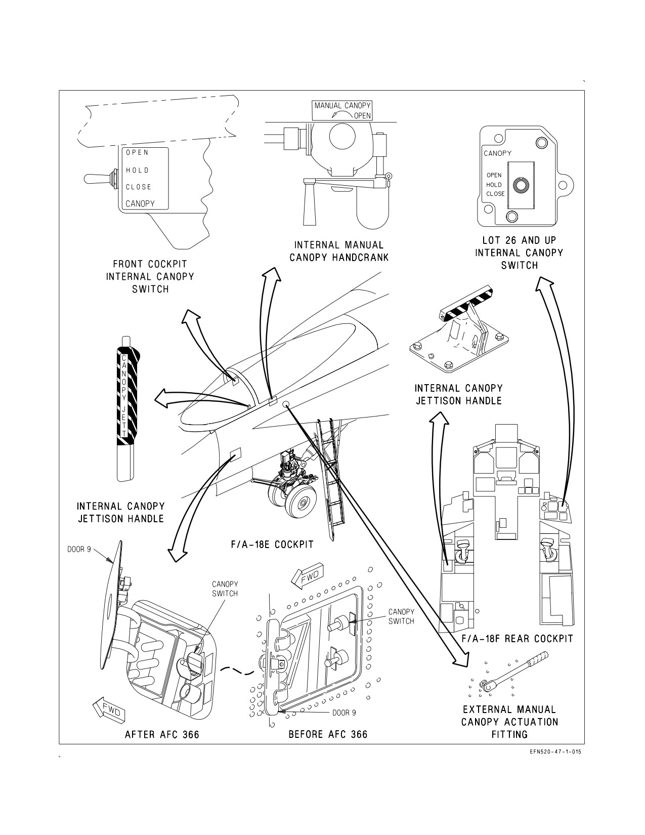
outboard of the pressure seal to divert rain water away from the cockpit. See figure 2-34.
I-2-115
ORIGINAL
A1-F18EA-NFM-000
A high voltage (100,000 volt) static electrical charge may build up in flight
and be stored in the canopy. If possible, make sure that ground crew
discharge the static electricity prior to egress. Otherwise, avoid direct
contact with the outside of the windscreen and canopy to prevent
electrical shock.
Taxiing with the canopy at an intermediate position can result in canopy
attach point damage and failure. Do not open or close the canopy with the
aircraft in motion.
2.16.1.1 Canopy Operation. During normal operation, the canopy is electrically actuated using
either the internal CANOPY switch or external canopy switch. The canopy actuator is powered by the
maintenance bus, which is powered directly by the battery in the absence of ac power (BATT switch
ON or OFF). On battery power, at least five open/close cycles should be available. With the canopy
open, the CANOPY switch must be held to lower the canopy to the rails, slide it approximately 1.5
inches forward, and lock it in place. With the canopy closed and locked, selecting OPEN on the
CANOPY switch (WonW) automatically unlocks and opens the canopy to the full up position. The
switch does not have to be held. Whether the canopy is opening or closing, selecting HOLD stops the
canopy at its present position.
If electrical power is not available, the canopy can be manually operated using either an internal or
external crank system. The canopy can be jettisoned using one of the internal CANOPY JETT
handles.
2.16.1.1.1 CANOPY Switch (Internal). The internal CANOPY switch is located beneath the right
canopy sill in the front cockpit. In LOT 26 and up, the rear cockpit CANOPY switch is located on the
lower right portion of the instrument panel. The CANOPY switch is spring loaded to the HOLD
position and is solenoid-held in the OPEN position only with WonW. The solenoid can be overridden
at any time by placing the switch to HOLD. With WoffW, the switch must be held in the OPEN
position to raise the canopy. Opposing position control commands between the front cockpit and rear
cockpit switches result in a fail-safe OPEN command.
OPEN
Unlocks and/or raises the canopy.
HOLD
Stops the canopy at any point during the open or close cycle.
CLOSE
Lowers and, if held, closes and locks the canopy (CANOPY caution out when
closed and locked).
2.16.1.1.2 Canopy Switch (External). The external canopy switch is located inside the external
power receptacle door (door 9) on the left side of the aircraft below the canopy and LEX. The switch
provides electrical operation of the canopy from outside the cockpit. The switch has the same positions
and operates identically to the internal CANOPY switch, except that the OPEN position is not
solenoid held. After AFC 366, the switch is guarded to prevent inadvertant actuation.
I-2-116
ORIGINAL
A1-F18EA-NFM-000
Figure 2-34. Canopy Controls
I-2-117
ORIGINAL
A1-F18EA-NFM-000
2.16.1.1.3 Manual Canopy Handcrank (Internal). The internal manual canopy handcrank is stowed
in a clip beneath the left canopy sill. The canopy can be manually opened or closed by inserting the
handcrank into the crank socket immediately above the stowage clip. Approximately 70 counterclock-
wise turns are required to fully open the canopy. Clockwise cranking closes the canopy. A cable is
provided to prevent loss of the handle if dropped.
2.16.1.1.4 Manual Canopy Actuation Fitting (External). The external manual canopy actuation
fitting, a 3/8 inch drive socket on the left side of the aircraft below the canopy, is used to manually
operate the canopy. Inserting a 3/8 inch drive tool in the socket and then turning counterclockwise
approximately 35 turns opens the canopy. Turning the drive tool clockwise closes the canopy.
2.16.1.2 Canopy Jettison System. For canopy jettison, a cartridge initiated thruster is utilized to
unlatch the canopy by moving it 1.5 inches rearward, after which two canopy frame mounted rocket
motors fire to rotate the canopy up and aft, clear of the ejection seat path. The thruster, which provides
attachment for the canopy actuator link during normal canopy operation, is activated by pulling the
ejection seat firing handle or internal canopy jettison handle(s) (figure 2-34). The canopy can be
jettisoned closed, open, or in any intermediate position.
2.16.1.2.1 CANOPY JETT Handle. The CANOPY JETT handle is black and yellow striped and is
located on the left inboard canopy sill just aft of the instrument panel in the front cockpit. Pressing the
button on the tip of the handle unlocks the handle. Pulling the handle aft initiates the canopy jettison
sequence. A ‘‘remove before flight’’ pin is used to manually secure the CANOPY JETT handle between
flights.
2.16.1.2.2 CANOPY JETT Handle (F/A-18F). The rear cockpit CANOPY JETT handle is black and
yellow striped and is located on the left console. Pressing the button on the forward tip of the handle
unlocks the handle. Pulling the handle up initiates the canopy jettison sequence. A REMOVE
BEFORE FLIGHT pin is used to manually secure the CANOPY JETT handle between flights.
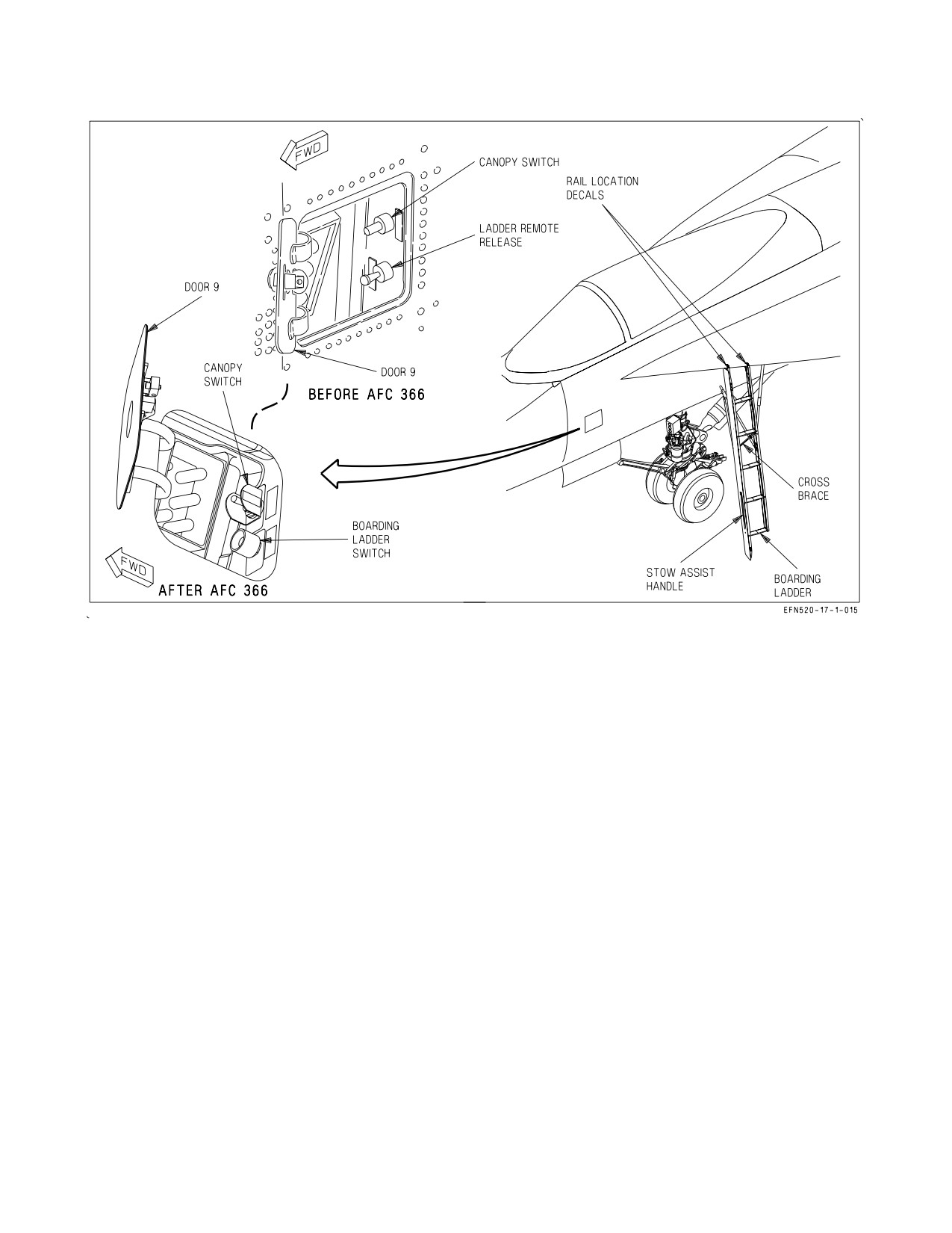
2.16.2 Boarding Ladder. A five-step boarding ladder (figure 2-35), stowed under the left LEX,
provides access to the cockpit and the top of the aircraft. Ladder extension and retraction can be
accomplished only from outside the cockpit, either manually or by the ladder remote release button
(after AFC 366) or switch (before AFC 366).
The ladder is extended manually by releasing the latch on the stow assist handle on the ladder’s left
rail (allowing it to drop slightly) and while supporting the ladder, rotating the stow assist handle to
vertical (releasing the remaining two mechanical uplocks on the underside of the LEX). The ladder
rotates down to the extended position. The stow assist handle is then secured. The drag brace locks
when extended to its full length to provide longitudinal stability for the ladder. Lateral stability is
provided by the V-shaped side brace attached to the side of the fuselage.
The LEX is narrow and highly sloped. Use caution to avoid loss of
footing.
NOTE
The ladder is not visible from the cockpit.
I-2-118
ORIGINAL
A1-F18EA-NFM-000
Normal cockpit egress is accomplished by grasping the canopy sill firmly with both hands, leaning
outboard and, using the ladder marking decals as a guide, stepping over the LEX toward the ladder.
The first step is approximately 15 inches below the leading edge of the LEX.
The ladder is stowed by detaching the rigid side brace connection from the fuselage. Pulling the
collar on the drag brace down permits the telescoping drag brace to unlock and compress as the
boarding ladder is rotated up and aft to the stowed position. The latches are manually engaged and
locked by pushing them full up until locked flush with the forward beam. If necessary, the stow assist
handle can be used to assist in stowing the ladder by releasing the handle and pushing the ladder to
the stowed position and pushing the stow assist handle to the closed (stowed) position and releasing it.
With electrical power on the aircraft, a LADDER caution comes on whenever the proximity switch in
the aft portion of the ladder well is not actuated. With the ladder stowed and the 3 latches locked, the
LADDER caution goes out.
The ladder is extended remotely by opening the ground power receptacle door and holding the
ladder remote release switch (lower switch) to the down (DEPLOY) position. The three latches are
opened by a battery powered actuator. The ladder drops to the open position while being restrained
from free falling by a dampening strut (drop time approximately 3 to 4 seconds). All other procedures
for securing the ladder are the same as manual opening.
2.16.2.1 Ladder Remote Release Switch (Before AFC 366). The external ladder remote release
switch is located inside the external power receptacle (door 9) on the left side of the aircraft below the
canopy and LEX. The switch is lever locked and spring loaded to the UP position. Switch positions are:
UP
Removes electrical power from the unlock actuators which allows the ladder to lock
when it is manually stowed.
DEPLOY Applies electrical power to the three unlock actuators which unlocks the actuators
so the ladder can free fall. The switch must be pulled out and down and held in
DEPLOY until the actuators are unlocked.
Due to the close proximity of the ladder remote release switch and the
external canopy switch, positive switch identification is required to
prevent inadvertently lowering the canopy and injuring personnel egress-
ing the aircraft.
2.16.2.2 Ladder Remote Release Button (After AFC 366). The guarded external ladder remote
release button is located inside the external power receptacle (door 9) on the left side of the aircraft
below the canopy and LEX. Pressing and holding the button applies electrical power to the three
unlock actuators which unlocks the actuators so the ladder can free fall.
2.16.3 Ejection Seat. The SJU-17 (V)1/A, 2/A, and 9/A, and SJU-17A (V)1/A, 2/A, and 9/A NACES
(Navy Aircrew Common Ejection Seat) are ballistic catapult/rocket systems that provide the pilot with
a quick, safe, and positive means of escape from the aircraft. See Ejection Seat, foldout section, for
ejection seat illustrations. The seat system includes an initiation system which, after jettisoning the
canopy and positioning the occupant for ejection, fires the telescopic seat catapult. Canopy breakers on
the top of the seat give capability of ejecting through the canopy. As the seat departs the aircraft and
the catapult reaches the end of the stroke a rocket motor on the bottom of the seat is fired. The thrust
I-2-119
ORIGINAL
A1-F18EA-NFM-000
Figure 2-35. Boarding Ladder
of the rocket motor sustains the thrust of the catapult to eject the seat to a height sufficient for
parachute deployment even if ejection is initiated at zero speed, zero altitude in a substantially level
attitude.
NOTE
Safe escape is provided for most combinations of aircraft altitude,
speed, attitude, and flight path within the envelope of 0 to 600 KCAS
airspeed and 0 to 50,000 feet.
2.16.3.1 SJU-17(V) 1/A, 2/A, and 9/A, and SJU-17A (V)1/A, 2/A, and 9/A NACES Seat. Timing of
all events after rocket motor initiation is controlled by the electronic sequencer which utilizes altitude,
acceleration, and airspeed information to automatically control drogue and parachute deployment and
seat/man separation throughout the ejection seat’s operational envelope. In the event of partial or total
failure of the electronic sequencer, a 4-second mechanical delay initiates a barostatic release unit which
frees the occupant from the seat and deploys the parachute between 14,000 and 16,000 feet MSL if the
ejection occurred in or above this altitude range. The emergency barostatic release unit operates
immediately after the 4-second delay if the ejection occurred below 14,000 feet MSL. An emergency
restraint release (manual override) system provides a backup in the event of failure of the barostatic
release unit. The seat is stabilized and the forward speed retarded by a drogue chute attached to the
top and bottom of the seat. The parachute deployment rocket is automatically fired to withdraw the
parachute from deployment bag. Full canopy inflation is inhibited until the g forces are sufficiently
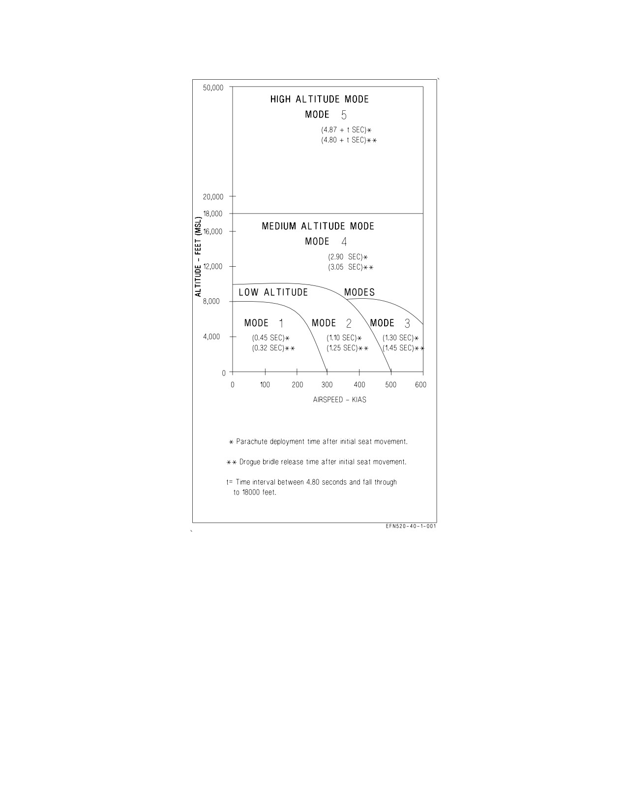
reduced to minimize opening shock. There are 5 modes of operation. See figure 2-36 for parameters
that determine the mode of operation and the corresponding parachute deployment and drogue chute
I-2-120
ORIGINAL
A1-F18EA-NFM-000
Figure 2-36. SJU-17 and SJU-17A Ejection Modes
release times. At high altitude the drogue chute deploys to decelerate and stabilize the seat. The seat
falls drogue retarded to 18,000 feet MSL where the drogue is released, the main parachute is deployed,
and seat/man separation occurs. At medium altitude, (between 18,000 and 8,000 feet MSL), and at low
altitude (below 8,000 feet MSL) parachute deployment is automatically delayed from 0.45 to 2.90
seconds (depending upon airspeed and altitude) after first seat motion to allow the drogue chute to
decelerate and stabilize the seat.
The main parachute is a 21 foot aeroconical canopy type, stored in a headbox container on top of the
ejection seat. The parachute is steerable and contains water deflation pockets which aid in dumping air
from the canopy after landing in water. The seat drogue chute is stored in a separate container on top
of the drogue deployment catapult. The seat contains controls for adjusting seat height and for locking
and unlocking the inertia reel shoulder restraint straps. A survival kit is installed in the seat pan.
I-2-121
ORIGINAL
A1-F18EA-NFM-000
2.16.3.2 SEAWARS - SEAWATER Activated Release System. SEAWARS is a seawater activated
system that automatically releases the parachute from the crew member. When the sensing-release
units are immersed in seawater, cartridges are fired which allow the crew member to separate from the
parachute.
2.16.3.3 Ejection Control Handle. The ejection control handle, located between the crewman’s legs
on the front of the seat pan, is the only means by which ejection is initiated. The handle, molded in the
shape of a loop, can be grasped by one or two hands. To initiate ejection, a 20 to 40 pound pull removes
the handle from its housing, and a continued pull of 30 to 60 pounds is required to pull both sears from
the dual initiators. Either of the initiators can fire the seat. After ejection, the handle remains attached
to the seat. The ejection control handle safes the ejection seat safe/armed handle.
2.16.3.4 Ejection Seat SAFE/ARMED Handle. To prevent inadvertant seat ejection, an ejection seat
safe/armed handle is provided. The handle, forward on the right seat armrest, safeties the seat when
rotated up and forward, and arms the seat when it is rotated aft and down. The safe/armed handle is
locked when placed to either of these two positions and the handle must be unlocked by squeezing a
locking lever within the handle cutout before changing positions. When in the armed position the
visible portion of the handle (from the occupant’s vantage point) is colored yellow and black with the
word ARMED showing. In the safe position, the visible portion is colored white with the word SAFE
showing. The seat is safe only when the word SAFE is entirely visible on the inboard side of the
SAFE/ARM handle and the handle is locked in the detent. Placing the handle to the SAFE position
causes a pin to be inserted into the ejection firing mechanism to prevent withdrawal of the sears from
the dual seat initiators.
2.16.3.4.1 CK SEAT Caution. The CK SEAT caution light is located on the caution light panel and
repeats the DDI CHECK SEAT caution. The caution comes on when the right throttle is at MIL or
above, weight is on wheels, and the ejection seat is not armed.
2.16.3.5 Shoulder Harness Inertia Reel. Pilot shoulder harness restraint is provided by a dual strap
shoulder harness inertia reel mounted in the seat below the parachute container. The dual inertia reel
shoulder straps connect to the parachute risers which in turn are buckled to the seat occupant’s upper
harness. The inertia reel locks when the reel senses excessive strap velocity. Manual locking and
unlocking of the reel is controlled by the shoulder harness lock/unlock handle on the left side of the
seat bucket. During ejection a pyrotechnic cartridge is fired to retract the shoulder harness to position
the seat occupant for ejection.
2.16.3.6 Shoulder Harness Lock/Unlock Handle. The shoulder harness lock/unlock handle on the
left side of the seat bucket has two positions. To operate, the handle must be pulled up against spring
pressure, moved to the desired position, and released.
FORWARD The inertia reel prevents the reel straps from being extended and ratchets any
(locked)
slack in the straps back into the reel.
AFT
The reel allows the pilot to lean forward, but the inertia portion of the reel contin-
(unlocked)
ues to protect by locking the reel when it senses excessive strap velocity. Once
locked, the pilot can normally lean forward again after a slight release in pressure
on the reel straps.
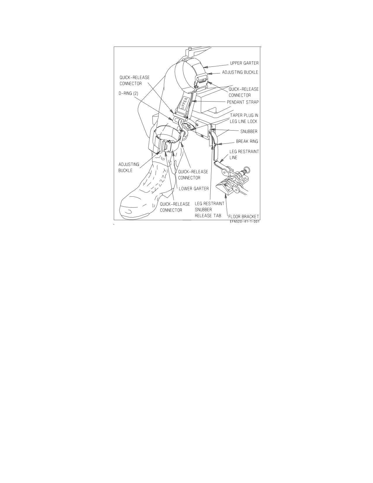
2.16.3.7 Leg Restraint System. A leg restraint system is located on the front of the ejection seat. The
function of the system is to secure the occupant’s legs to the seat during ejection. The system consists
of two adjustable leg garters, a restraint line, and a snubber box for each leg. One garter is worn on the
I-2-122
ORIGINAL
A1-F18EA-NFM-000
Figure 2-37. Leg Restraint System
thigh and one on the lower leg. The restraint lines are routed through the garter rings and the snubber
box as shown in figure 2-37. One end of each restraint line is secured to the cockpit floor and the other,
after being routed through the snubber box and both garter rings, is secured to the seat just outboard
of the snubber box by a releaseable pin. During ejection, the slack in each line is taken up and the
tension builds up to finally separate the lines at the tension rings in the leg lines. At man/seat
separation, the pins on the other end of the lines are released by the time release mechanism. The pins
are also released when the manual override handle is pulled. Both the lower garter and thigh garter
contain a quick release buckle which disconnects the ring through which the leg restraint line runs,
permitting the pilot to egress from the aircraft wearing both upper and lower garters. In addition, toe
clips are installed on the tops of the rudder pedals to prevent contact between the toes and the
instrument panel during ejection.
2.16.3.7.1 Leg Restraint Snubber Release Tabs. The leg restraint lines are adjusted to give the pilot
more leg movement by pulling inboard the leg restraint snubber release tabs (figure 2-37) and
simultaneously pulling the leg restraint lines forward through the snubber box.
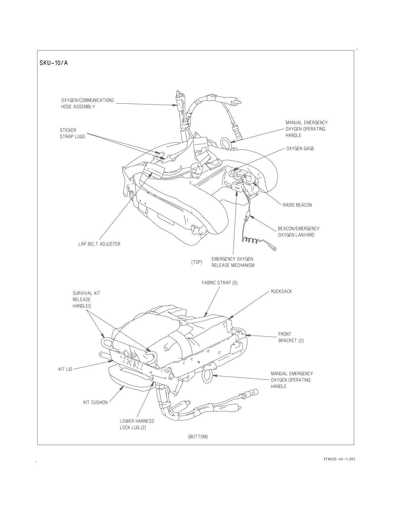
2.16.3.8 Seat Survival Kit (SKU-10/A). The SKU-10/A survival kit is used with the SJU-17 and
SJU-17A ejection seats. This survival kit, which fits into the seat bucket, is a contoured rigid platform
which contains an emergency oxygen system and a fabric survival rucksack (figure 2-38). A cushion on
top of the platform provides a seat for the aircrew.
The rigid platform forms a hard protective cover to the survival package and oxygen system and is
retained in position in the seat bucket by brackets at the front and lugs secured in the lower harness
locks at the rear. Attached to the lugs are two adjustable lap belts with integral quick release fittings.
A flexible oxygen and communication hose is installed in the left aft side of the upper kit to provide
a connection to the aircrew for aircraft oxygen and communication. An emergency oxygen cylinder,
I-2-123
ORIGINAL
A1-F18EA-NFM-000
Figure 2-38. Survival Kit
I-2-124
ORIGINAL
A1-F18EA-NFM-000
pressure reducer, and associated pipe work are mounted on the underside of the platform. A green
manual emergency oxygen operating handle is mounted on the left side of the platform and a pressure
gage is on the inside face of the left leg support. The emergency oxygen can be activated manually by
pulling the green emergency oxygen handle upwards. The green emergency oxygen handle can be reset,
shutting off the flow of emergency oxygen, by pushing downward on the button on the front end of the
emergency oxygen handle assembly. The emergency oxygen is automatically activated during ejection
by a lanyard connected between the floor and the survival kit. An AN/URT-33A locator beacon is
located in a cutout in the left leg support. The beacon is actuated during ejection by a lanyard
connected to the emergency oxygen lanyard.
The survival rucksack is retained to the underside of the rigid platform by 5 fabric straps and a
double cone and pin release system. The package accommodates a life raft and survival aids. Two
yellow manual deployment handles are mounted on the aft surface of the kit. Pulling either handle
enables the aircrew to deploy the raft and survival package after man/seat separation. The life raft
inflates automatically on survival package deployment and is attached to the survival package with a
line. If the survival kit must be deployed after water entry, a snatch pull on the red manual activation
handle near the CO2 bottle is required to inflate the life raft.
2.16.3.9 Manual Override Handle. A manual override handle permits releasing the pilot’s lower
harness restraints and the leg restraint lines for emergency egress and permits resuming part of the
ejection sequence (man/seat separation and main parachute deployment) in the event of sequencing
failure during ejection. The manual override handle, on the right side of seat bucket and just aft of the
ejection seat safe/arm handle, is actuated by pressing a thumb button on the forward part of the handle
and rotating the handle up and aft. If the manual override handle is actuated on the ground or in the
air before ejection, survival kit attachment lugs and leg restraint lines are released, the inertia reel is
unlocked, and the ejection seat safe/armed handle automatically rotates to the SAFE position. During
ground emergency egress, after the manual override handle is pulled and the parachute riser fittings
are released, the pilot is free to evacuate the aircraft with the survival kit still attached. If the manual
override handle is actuated after ejection but before man/seat separation occurs, the following events
take place: release of survival kit attachment lugs, negative-g strap (SJU-17 (V)1/A, 2/A, and 9/A only),
leg restraint lines, and inertia reel straps; firing of the manual override initiator cartridge; firing of the
barostatic release unit; and firing of the parachute deployment rocket, which deploys the parachute.
The ejection seat safe/armed handle automatically rotates to the SAFE position whenever the manual
override handle is actuated.
Pulling the manual override handle automatically rotates the ejection
seat safe/armed handle to the SAFE position, releases the survival kit
attachment lugs and leg restraint lines, and unlocks the inertia reel. If
this is done inflight, the aircrew will be unable to eject.
2.16.3.10 Seat Bucket Position Switch. The seat bucket position switch is on the left side of the seat
bucket, forward of the shoulder harness lock/unlock handle. The forward switch position lowers the
seat bucket, the aft position raises the seat bucket. The center off position, to which the switch is spring
loaded, stops the seat bucket. The maximum vertical travel of the seat bucket is 5.1 inches for the
I-2-125
ORIGINAL
A1-F18EA-NFM-000
SJU-17 (V)1/A, 2/A, and 9/A, and 6.1 inches for the SJU-17A (V)1/A, 2/A, and 9/A. The actuator
should not be operated over 1 minute during any 8 minute period.
• To prevent increased risk of thigh slap or leg contact injuries, aircrew
with a buttock-to-knee length greater than 25.5 inches should not use
either of the two forward backpad positions. Aircrew with buttock-to-
knee length between 24.6 and 25.5 inches should not use the full
forward backpad position.
• Actuation of the seat bucket position switch with the leg restraints
under the seat bucket may result in an inadvertent ejection.
Actuation of seat bucket position switch with lap belts, shoulder harness,
and/or leg restraints outside or under seat bucket may damage ejection
seat, leg restraints, and/or Koch fittings.
2.16.3.11 Backpad Adjustment Mechanism (SJU-17A (V)1/A, 2/A, and 9/A). The backpad adjust-
ment mechanism handle is on the seat bucket adjacent to the top left hand side of the backpad and is
connected to the backpad by a linkage. The backpad has three positions, full-forward, middle, and full-
aft, which give a total forward/aft adjustment of 1.6 inches. When the handle is in the full-up position,
the backpad is full-aft, and when the handle is full-down, the backpad is full-forward. To move the
backpad, the adjustment handle is moved within a quadrant until a spring-loaded plunger engages in
one of the three detent positions in the quadrant. Set the backpad for personal comfort and best access
to flight controls during initial strap-in and prior to flight.
2.16.4 Ejection Seat System (F/A-18F). The ejection seats in the F/A-18F are ejected at opposite
divergent angles to one another. The rear seat diverges to the left while the forward seat diverges to the
right. The amount of divergence is influenced by the weight of the aircrew and the speed of the ejection.
The heavier the aircrew and the faster the speed the less the resulting divergent angle. In addition, a
sequencing system is installed to allow dual ejection initiated from either cockpit or single (aft) seat
ejection initiated from the rear cockpit. A command selector valve is installed in the rear cockpit to
control whether ejection from the rear cockpit is dual or single.
2.16.4.1 EJECTION MODE Handle (F/A-18F). The EJECTION MODE handle is located on the right
side of the main instrument panel in the rear cockpit. The EJECTION MODE handle is used to select
the desired ejection sequence to be initiated from the rear cockpit, or provide for single ejection for solo
flight. Positioning is accomplished by pulling out while turning to the desired position. The SOLO
position requires the use of a collar to hold the handle in that position. To release from AFT
INITIATE, pull then turn clockwise.
NORM
Single rear seat ejection when initiated from the rear cockpit. Dual ejection (rear
(vertical)
seat first) when initiated from the front cockpit.
I-2-126
ORIGINAL
A1-F18EA-NFM-000
AFT
Dual ejection (rear seat first) when initiated from either cockpit.
INITIATE
(horizontal)
SOLO
Front seat ejection only when initiated from the front cockpit. Front seat ejection
(45° CCW)
is immediate. Rear seat ejection only when initiated from the rear seat. Rear seat
ejection is immediate.
• SOLO mode shall NOT be selected when both seats are occupied. If
SOLO mode is selected when both seats are occupied, simultaneous
ejection initiation may result in a collision between seats.
• SOLO mode shall be selected when the aircraft is being flown solo.
Alternate selection when flying solo results in ejection of unoccupied
seat and possible collision with the front cockpit seat.
When selecting NORM or SOLO from AFT INITIATE, the handle must
be pulled before rotation or damage to the command selector valve may
result.
2.16.4.2 SEAT CAUT MODE Switch (F/A-18F). The SEAT CAUT MODE switch is located in the
rear cockpit above the command selector valve. The switch position changes the operation of the CK
SEAT caution for solo or dual flight.
NORM
CK SEAT caution is activated by either seat remaining safed. Switch is spring
loaded to this position.
SOLO
CK SEAT caution is activated only by the front seat remaining safed. Switch must
be pinned to remain in this position.
2.16.4.3 CK SEAT Caution (F/A-18F). The CK SEAT caution light is located on the caution light
panel, and repeats the DDI CHECK SEAT caution display. The caution is displayed when the right
throttle is at MIL or above, weight is on wheels, and the cockpit ejection seat is not armed with the rear
cockpit NORM/SOLO switch set to SOLO or either ejection seat is not armed with the NORM/SOLO
switch set to NORM.
2.17 EMERGENCY EQUIPMENT
2.17.1 Jettison Systems. The jettison systems consist of the emergency jettison system and the
selective jettison system.
2.17.1.1 Emergency Jettison. Emergency jettison is performed by pushing the EMERG JETT
button with either the LDG GEAR handle UP or with WoffW. When activated, the emergency jettison
system jettisons all stores, launchers, and racks from the BRU-32 racks on the six wing pylon stations
I-2-127
ORIGINAL
A1-F18EA-NFM-000
(2, 3, 4, 8, 9, and 10) and the centerline station (6). Emergency jettison is sequential by station pairs:
3 and 9, 2 and 10, 4 and 8, then 6. There is a 100 msec, ±25 msec, delay before the first set of stations
is jettisoned and in between each subsequent set.
2.17.1.2 EMERG JETT Button. The EMERG JETT button is located on the left side of the main
instrument panel and is black and yellow striped. The button must be pressed and held during the
entire jettison sequence. The EMERG JETT button is used to initiate emergency jettison with the
LDG GEAR handle UP or with WoffW.
The EMERG JETT button must be pressed for 500 msec to make sure all
stores are jettisoned.
If the EMERG JETT button has been pushed on the ground prior to
takeoff and remains stuck in, emergency jettison is activated as soon as
the aircraft goes WoffW. The only cockpit indication of this condition is
SMS BIT status DEGD and MSP 082 (Emergency Jettison Switch Failed
On).
2.17.1.3 Selective Jettison. Selective jettison is performed using the SELECT JETT knob, in
conjunction with the JETT STATION SELECT buttons, and jettisons stores in a safe condition. The
stores or the launchers/racks (with any attached stores) can be jettisoned from the centerline and wing
stations, and the missiles can be jettisoned from the fuselage stations.
Selective jettison requires ARM conditions satisfied and all the landing gear up and locked. ARM
conditions are satisfied with WoffW, LDG GEAR handle UP, MASTER ARM switch in ARM, and
SIM mode unboxed. ARM status can be confirmed on the STORES page. All the landing gear up and
locked can be confirmed by the absence of the LDG GEAR handle warning light/landing gear warning
tone with the LDG GEAR handle UP.
Selective jettison of the centerline and wing stations requires station(s) selection by the JETT
STATION SELECT buttons and STORES or RACK/LCHR selection by the SELECT JETT knob.
Selective jettison of a fuselage station missile requires R FUS MSL or L FUS MSL selection by the
SELECT JETT knob.
With all the requirements met, selective jettison is performed by pressing the JETT center
pushbutton in the SELECT JETT knob.
2.17.1.3.1 JETT STATION SELECT Buttons. The JETT STATION SELECT buttons are on the left
edge of the instrument panel below the emergency jettison button. The buttons are labeled CTR, LI,
RI, LM, RM, LO and RO. Pressing a button turns on an internal light and selects a weapon station for
jettison. The JETT STATION SELECT buttons are also used in the backup A/G weapon delivery
modes for weapon selection; refer to A1-F/A-18EA-TAC (Series).
2.17.1.3.2 SELECT JETT Knob. The SELECT JETT knob on the left vertical panel has rotary
positions L FUS MSL, SAFE, R FUS MSL, RACK/LCHR, and STORES. L FUS MSL and R FUS
MSL select either fuselage missile for jettison. The RACK/LCHR and STORES positions select what
I-2-128
ORIGINAL
A1-F18EA-NFM-000
is to be jettisoned from the weapon station(s) selected by the JETT STATION SELECT buttons. The
JETT center pushbutton activates the jettison circuits provided ARM conditions are satisfied and all
the landing gear are up and locked. The SAFE position prevents any selective jettison.
2.17.1.3.3 AUX REL Switch. The AUX REL switch, on the lower instrument panel, is used to enable
jettison of hung stores or store and rack/launcher combinations from BRU-32 racks on stations 2, 3, 4,
6, 8, 9, and 10. A need to use the AUX REL switch is indicated by a hung indication on the DDI after
a selective jettison or a normal weapons release is attempted. Placing the switch to ENABLE selects
the auxiliary release function. AUX RELEASE has the same requirements as those listed above for
selective jettison. Jettison is initiated by selecting RACK/LCHR or STORES on the selective jettison
knob, selecting the hung store station by pressing the appropriate station jettison select button, and
pressing the JETT center pushbutton of the selective jettison knob. The SMS provides a jettison signal
to fire the auxiliary cartridge in the BRU-32 rack on which the hung store or store and rack/launcher
combination is loaded. After the cartridge is fired, the store or rack/launcher is gravity dropped with
the store in a safe condition. This switch is also used with some weapons for a second normal release
attempt after these weapons have been hung during a first normal release attempt. Refer to
A1-F18EA-TAC-Series for these weapons and procedures.
2.17.2 Warnings/Cautions/Advisories. The warning/caution/advisory system provides visual indi-
cations of normal aircraft operation and system malfunctions affecting safe operation of the aircraft.
The lights are on various system instruments and control panels in the cockpit. The red warning lights
normally indicate a systems malfunction that could be a severe hazard to further flight, and may
require immediate action. Caution lights and displays normally, but not always, indicate malfunctions
that require attention but not immediate action. After the malfunction has been corrected, warning
and caution lights and caution displays go out. Advisory lights and displays indicate safe or normal
conditions and supply information for routine purposes. Warning, caution and advisory displays are
NVG compatible. Caution and advisory displays appear on the left or right DDI and the MPCD,
depending on the number of displays in operation. The advisory displays start at the bottom of the
display and are preceded by ADV. The caution displays, in larger characters than the advisory displays,
appear immediately above the advisory displays. The caution lights, located on the caution lights panel
and the instrument panel, are yellow lights. The advisory lights, scattered throughout the cockpit(s),
are green. Lights that have been lit on the caution lights panel flash when overheated to prevent light
damage.
2.17.2.1 MASTER CAUTION Light. A yellow MASTER CAUTION light, on the upper left part of the
instrument panel, comes on when any of the caution lights or caution displays come on. The MASTER
CAUTION light goes out when it is pressed (reset). An audio tone is initiated whenever the MASTER
CAUTION light comes on. The tone is of 0.8 second duration and consists of a 0.25 second sound
followed by a 0.15 second sound of higher pitch, followed by one repetition of these sounds. The tone
does not repeat unless the original condition causing the tone clears and recurs 5 seconds after the first
tone, regardless of whether or not the MASTER CAUTION is reset. Additional cautions sound the
tone, regardless of whether or not the MASTER CAUTION is reset, providing about 5 seconds have
elapsed since the previous caution. Pressing the MASTER CAUTION when it is unlighted causes the
uncorrected caution and advisory displays to reposition to the left and to a lower level, provided there
is available space vacated by corrected caution and advisory displays. To restack the cautions and
advisories when the MASTER CAUTION is lighted, the MASTER CAUTION must be pressed twice:
first, to turn off the MASTER CAUTION light and second, to reposition the caution and advisory
displays. A reset MASTER CAUTION light (and tone) comes on if there is at least one uncorrected
caution present when weight is on the wheels and both throttles are moved beyond approximately 80%
rpm if both throttles were below 80% for at least 60 seconds.
I-2-129
ORIGINAL
A1-F18EA-NFM-000
2.17.2.2 MASTER CAUTION Light (F/A-18F). A yellow MASTER CAUTION light, on the upper
instrument panel comes on whenever the MASTER CAUTION light in the front cockpit comes on.
The rear cockpit MASTER CAUTION light goes out whenever the front cockpit MASTER CAUTION
is reset.
2.17.2.3 Dimming and Test Functions. There are no provisions for testing the caution and advisory
displays and each DDI contains its own display dimming controls. The warning/caution/advisory lights
are dimmed by the warning/caution lights knob and are tested by the lights test switch. The following
lights can be dimmed by the warning/caution lights knob, but once in the dimmed lighting range
cannot be varied in intensity: MASTER CAUTION light, landing gear handle warning, L BAR
warning, HOOK warning, L BLEED warning, R BLEED warning, APU FIRE warning, left and right
engine FIRE warning.
2.17.3 Voice Alert System. For certain critical warnings and cautions, voice alert transmissions are
sent to the aircrew’s headset. The message is repeated twice; for example, APU FIRE, APU FIRE. The
voice alert requires no reset action on the pilot’s part and the alert is not repeated unless the original
condition ceases for 5 seconds or more and then recurs. For cautions with voice alert, the voice alert
replaces the master caution tone; however, the master caution tone backs up the voice alert system and
provides a tone if the voice alert system malfunctions. FIRE, APU FIRE, L BLEED, and R BLEED
warning lights are not backed up by the master caution tone. Voice alert is the only audio warning for
these problems. With dual generator failure, the following voice alert warnings operate from battery
power: APU FIRE, ENGINE FIRE LEFT (RIGHT), and BLEED AIR LEFT (RIGHT). All voice alert
cautions, and the master caution tone are inoperative on battery power during dual generator failure.
Once a voice alert has been activated, it cannot be interrupted by a higher priority voice alert. All
voice alerts play until completed. The primary radar low altitude warning (WHOOP, WHOOP), is
repeated at the lowest priority until reset or disabled by the pilot. With MC OFP 20X AND UP OR
H3E AND UP, the BINGO voice alert is repeated every 30 seconds until the BINGO setting is
adjusted.
NOTE
With an MC1 failure (LOTs 21-24), the voice alert does not sound
when the aircraft descends below the altitude set by the primary low
altitude warning setting.
I-2-130
ORIGINAL
A1-F18EA-NFM-000
CAUTION
VOICE ALERT
IFF 4
MODE 4 REPLY
FCS
FLIGHT CONTROLS
FCS HOT
FLIGHT COMPUTER HOT
L (R) OVRSPD
L (R) EGT HIGH
L (R) FLAMEOUT
ENGINE LEFT (RIGHT)
L (R) OIL PR
L (R) STALL
L (R) ENG
L (R) ENG VIB
FUEL LO
FUEL LOW
BINGO
BINGO
WARNING
VOICE ALERT
ALTITUDE
ALTITUDE
L (R) BLEED AIR
BLEED AIR LEFT (RIGHT)
L (R) FIRE
ENGINE FIRE LEFT (RIGHT)
APU FIRE
APU FIRE
2.17.4
Terrain Awareness Warning System (TAWS) (MC OFP 18EA and H2E AND UP). The terrain
awareness warning system alerts the aircrew of a controlled flight into terrain (CFIT) condition during
all mission phases. The system operates any time that the navigation mission computer (MC1) and
TAMMAC digital mapping set (DMS) are functional. TAWS functions as a safety backup system and
not as a performance aid. TAWS has been designed to eliminate false warnings, minimize nuisance
warnings, and generate consistent aircrew response in all aircraft master modes. Five possible voice
warnings are provided to indicate the correct initial response to an impending CFIT condition, and a
visual cue is provided to indicate the recovery direction of pull, or in some instances, to command an
increase in turn rate. All TAWS warnings should be treated as though an imminent flight into terrain
condition exists. Pilot response to a TAWS warning should be instinctive and immediate.
TAWS uses data from the following inputs: FCC, INS, RADALT, GPS, and digital terrain elevation
data (DTED). DTED resides in the DMS as part of TAMMAC and is used to provide the
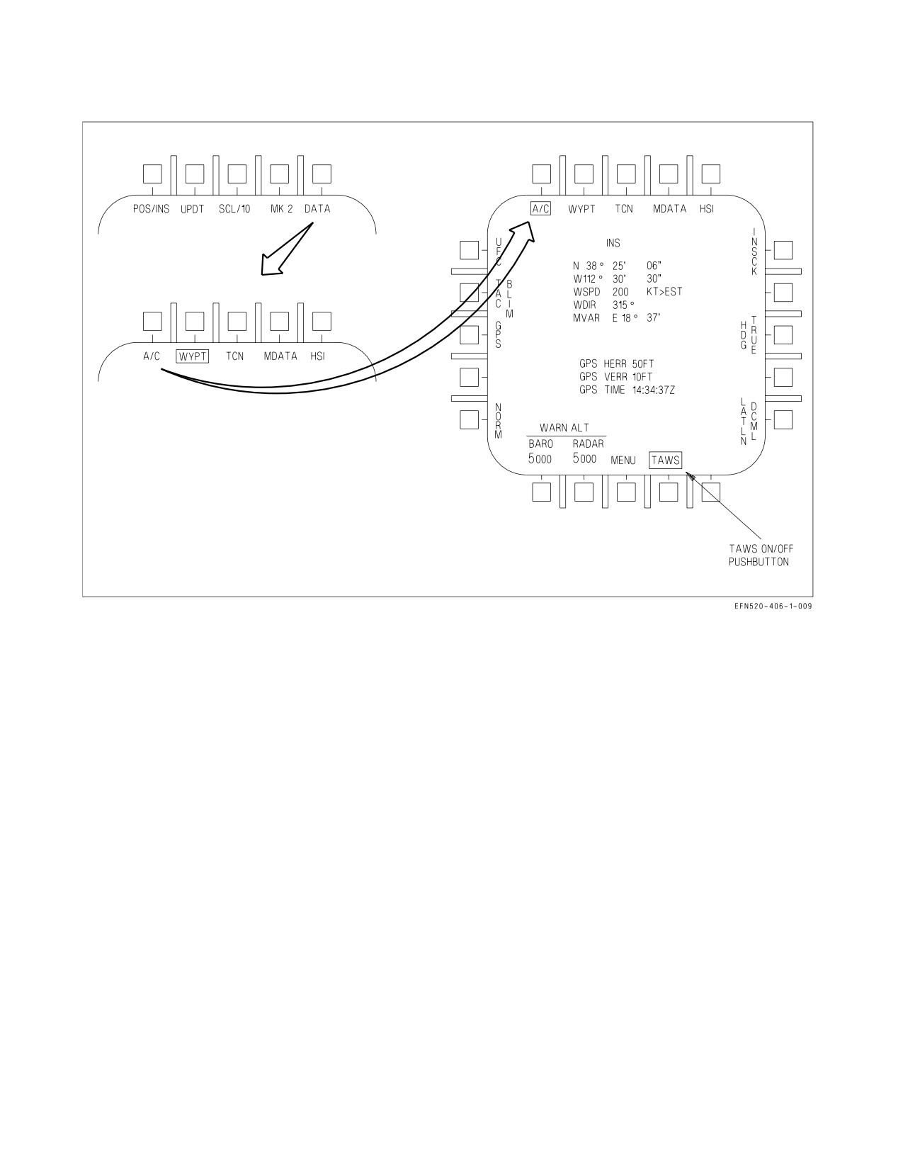
forward-prediction capability that protects against flight into rising terrain. The TAWS option is
reached by pressing MENU-HSI-DATA-A/C as shown in figure 2-39. The TAWS option boxes
automatically at start-up.
When a DMS is not installed in the aircraft or is not operational, protection from CFIT events is
provided by the Ground Proximity Warning System (GPWS). BIT may be initiated on the DMS by
pressing the appropriate pushtile of the BIT display. The BIT can take up to 185 seconds to complete.
During the BIT, TAWS is not operational. Therefore, the GPWS algorithm is used to determine the
presence of possible CFIT events. There is no capability for pilot selection of GPWS if DMS is
I-2-131
ORIGINAL
A1-F18EA-NFM-000
Figure 2-39. HSI-DATA-A/C Controls
operational. The GPWS algorithm runs continuously with outputs being overwritten if TAWS is
operational. This prevents erroneous values during an unexpected transition from TAWS to GPWS.
2.17.4.1 TAWS Modes. TAWS has two operational modes: TAWS-with-DTED, and TAWS- without-
DTED. These modes switch automatically depending upon the available sensor data and flight phase.
When the aircraft position (latitude and longitude) is accurately known and DTED for the local area
has been loaded onto the DMS (during the theater load process), TAWS is in the TAWS-with-DTED
mode and provides protection against varying terrain ahead of the aircraft. When the aircraft position
is not accurately known, DTED for the local area is unavailable, or TAWS determines the aircraft is
in a landing phase, TAWS transitions to the TAWS-without-DTED mode and provides protection
against flight into level or descending terrain as GPWS does.
When operating over the ocean, DTED does not exist and TAWS will be in the TAWS-without-
DTED mode. However, there is no degradation in protection because the ocean is relatively flat. As the
aircraft approaches the coast or islands, DTED may be available (depending upon the theater load)
and TAWS will automatically switch back to the TAWS-with-DTED mode.
Operation of TAWS in the TAWS-without-DTED mode is still an improvement over GPWS as
TAWS incorporates a more robust performance model and additional input sensor redundancy.
2.17.4.2 TAWS Operation. TAWS incorporates signal processing that determines a best estimate of
aircraft position and altitude (AGL and MSL). TAWS protection algorithm continuously computes
two recovery trajectories: Vertical Recovery Trajectory (VRT) and Oblique Recovery Trajectory
(ORT). VRT is the standard GPWS-like recovery: roll to wings-level, if needed, and pull to recover.
I-2-132
ORIGINAL
A1-F18EA-NFM-000
ORT assumes that you maintain the current bank angle and pull to recover (increase turn rate). Both
computed trajectories include the following assumptions:
a. Pilot Response Time is the time from issuance of a TAWS warning to the time that the pilot
actually initiates recovery. Pilot Response Time is set at 1.3 seconds.
b. Roll Recovery Phase is the time necessary to roll the aircraft to near wings-level. This assumes
at least ½ lateral stick will be used for bank angles less than 70° and at least ¾ lateral stick
will be used for bank angles ≥ 70°.
c. G-Onset Phase is the time required to pull to the target recovery g. The target recovery g is
80% of the instantaneous g available, or 5g, whichever is less. The g-onset phase assumes that
rapid aft stick motion will be used (full deflection within ¾ second). In addition, TAWS
assumes that throttles will be moved to MAX if below corner speed and to IDLE if above
corner speed.
d. Dive Recovery Phase is the remainder of the trajectory until terrain clearance is achieved.
TAWS assumes a terrain clearance of 50 ft.
When TAWS senses that the aircraft is in the landing configuration, the recovery assumptions must
change since the desire is to land. TAWS defines the landing phase as below 500 ft AGL, less than 200
KCAS, landing gear down and locked, and more than one minute since a waveoff or takeoff. In the
landing phase, TAWS protects against landings of greater than the structural limit of the landing gear
(1584 fpm). To allow this, TAWS switches to TAWS-without-DTED and provides a warning when the
landing is predicted to exceed the structural limit of the landing gear.
TAWS provides protection against gear-up landings. When the aircraft is below 200 KCAS, below
150 ft AGL, more than one minute since waveoff or takeoff, and the landing gear is not down and
locked, a TAWS warning is provided.
2.17.4.3
TAWS Warnings. TAWS provides clear, unambiguous, and directive aural and visual cues
to the aircrew. Aural warnings provide the aircrew with a wake-up call and correct initial response
while visual warnings provide the aircrew with correct follow-on recovery information.
2.17.4.3.1 Voice Warnings. TAWS uses the ACI to provide aural cues to the aircrew. The aural cues
are distinct from any other cues that the aircrew may receive. The TAWS voice alert warnings are:
″Roll−Left...Roll−Left″,
″Roll−Right
Roll−Right″,
″Pull−Up...Pull−Up″,
″Power...Power″, and
″Check Gear″. Each of these warnings is issued at a level 3−6 dB above the present voice alerts. The
TAWS voice warnings provide a wake−up call to the aircrew and indicate the most appropriate initial
response for the given aircraft state, not necessarily the only required response. The aural cue repeats
until the warning condition is cleared. TAWS aural warnings have priority over all current aural tones.
Note that TAWS requires a -1018 or greater ACI load (or MIDS equivalent) which is capable of
generating the ″Roll Left/Right″ warnings. Earlier ACI loads were only capable of generating ″Roll
Out″ warnings and are not desired for use with TAWS.
A ″Roll Right...Roll Right″ warning is issued when a roll to the right is the correct initial response.
A ″Roll Left...Roll Left″ warning is issued when a roll to the left is the correct initial response.
A ″Power...Power″ warning is issued when the roll requirement conditions have not been met and
adding power is the correct initial response. This occurs when the aircraft is below 200 KCAS, the AOA
I-2-133
ORIGINAL
A1-F18EA-NFM-000
Figure 2-40. TAWS HUD Visual Recovery Warning - Pull Up (VRT)
is above 8.5° for PA configuration (or 18° AOA for up and away configuration) and the throttle is not
already at MAX. The correct response to this warning is to select MAX afterburner.
A ″Pull Up...Pull Up″ warning is issued when the above conditions have not been met and pulling up
is the correct response or when the ORT is the recovery trajectory.
When a warning is given to protect against a gear-up landing, the following aural cues may be heard:
″Pull Up...Pull Up″ followed two seconds later by ″Check Gear″ when the gear handle is in the UP
position and a gear-up landing condition has been assessed (repeated every 4 seconds).
″Check Gear″ repeated every 8 seconds when the gear handle is down and a gear up landing condition
has been assessed.
2.17.4.3.2
Visual Warnings. A visual recovery arrow is provided in the center of the HUD and HUD
format on the DDI. The recovery arrow indicates the direction of recovery. The visual warning is
displayed when a CFIT condition is present and is removed when the CFIT condition is cleared.
TAWS visual recovery cues are designed to be used in conjunction with TAWS voice warnings.
There are several voice warning/visual recovery cue combinations. When the arrow points UP in the
HUD (i.e., along the lift vector), a longitudinal pull is the correct response and an aural ″Pull Up...Pull
Up″ is heard. This is a VRT recovery if the aircraft is close to wings level, or it is an ORT (increased
turn rate) recovery if the aircraft is banked such that the TAWS algorithm assessed that an increased
turn rate would provide the quickest recovery from an impending CFIT condition. Figures 2-40 and
2-41 depict these two situations. Both situations require a longitudinal pull as the correct response,
however, the first case (VRT) depicts a dive recovery while the second case (ORT) depicts a recovery
requiring an increase in turn rate by increasing g when already in an established angle of bank.
When the arrow points anywhere other than UP in the HUD (i.e., not along the lift vector, but
perpendicular to the horizon), it may be accompanied by either a ″Roll Left (Right)″...″Roll Left
(Right)″ or ″Pull Up...Pull Up″ voice warning. The voice warning indicates the correct initial response,
then the aircrew should roll or pull as required to place or maintain the TAWS recovery arrow straight
up in the HUD (i.e., along the lift vector). For example, if a ″Roll Left...Roll Left″ voice warning is
issued with an accompanying HUD recovery arrow displayed in the HUD that is perpendicular to the
I-2-134
ORIGINAL
A1-F18EA-NFM-000
Figure 2-41. TAWS HUD Visual Recovery Warning - Pull Up (ORT)
horizon, the correct response is to roll left to align the lift vector with the HUD recovery arrow and then
perform a dive recovery. If a ″Pull Up...Pull Up″ voice warning is issued with an accompanying HUD
recovery arrow displayed in the HUD that is perpendicular to the horizon, the correct response is to
apply g along the current lift vector and then, referencing the HUD recovery arrow, roll to align the lift
vector with the HUD recovery arrow and perform a dive recovery. Figure 2-41 depicts a situation in
which a Roll or Pull Up aural warning could be issued. If a ″Roll Right...Roll Right″ aural warning was
issued, a roll to the right would be the correct initial response and then a dive recovery would be
continued with a longitudinal pull. If a ″Pull Up...Pull Up″ aural warning was issued, a longitudinal pull
would be the correct initial response and then a roll to the right to align the lift vector with the HUD
recovery arrow followed by a longitudinal pull for a dive recovery would be the follow-on recovery
procedure.
2.17.4.4 ACI Configuration Check. There are different ACI configurations in the F/A-18 aircraft.
Two TAWS software loads exist: -1016 and -1018. The -1016 ACIs can command these four aural cues:
″Roll Out...Roll Out″, ″Pull Up...Pull Up″, ″Check Gear″, and ″Power...Power″. The -1018 and greater
ACIs added logic for replacing the ″Roll Out...Roll Out″ aural cue with ″Roll Left...Roll Left″ and ″Roll
Right...Roll Right″. Due to the variety of possible combinations, on cold start power-up, the MC
commands a ″Roll Left...Roll Left″ to the ACI to determine if it is in the -1018 configuration. If there
is no response, the MC commands a ″Roll Out...Roll Out″ to the ACI to determine if the ACI is in the
-1016 configuration. If no response is received the second time the MC attempts to command a ″Roll
Out...Roll Out″, the TAWS/GPWS voice warnings will not be heard, however the visual arrow will still
be present when a warning is issued.
2.17.5 GPWS - Ground Proximity Warning System. GPWS is designed to backup the pilot by
providing an alert of impending controlled flight into terrain (CFIT). GPWS provides warnings of
potentially unsafe maneuvering flight conditions such as excessive bank angles, excessive sink rates,
gear up landings, floor altitude violations, and altitude loss during recovery. The system is operational
as long as MC1, radar altimeter, and air data systems are ON and functional. The GPWS algorithm
operates in the backg1round of the OFP with no cockpit indications until an actual CFIT warning is
required. The system provides distinctive aural and visual warning cues only, to alert and direct
recovery from an impending CFIT condition. The pilot maintains full control of the aircraft for
recovery.
I-2-135
ORIGINAL
A1-F18EA-NFM-000
Figure 2-42. TAWS HUD Visual Recovery Warning (VRT)
2.17.5.1 GPWS Sensors/Modes. GPWS is a look-down system with no forward-looking capability.
GPWS uses the radar altimeter as the primary source of terrain clearance information and the FCC air
data function, GPS, and INS as backup altitude sources when radar altitude is invalid. Radar altitude
is considered invalid by GPWS above 4,950 feet AGL or at a pitch or angle of bank greater than 50°.
With valid radar altitude data, GPWS calculates terrain slope from inputs from the INS and the radar
altimeter. Over descending terrain, GPWS assumes the terrain descends indefinitely (until the system
senses a change in terrain slope). This mechanization allows for maximum protection while minimizing
nuisance warnings.
For the first 5 seconds after radar altitude becomes invalid (as indicated by a flashing ″B″ in the
HUD or RALT Xd out on the UFCD), GPWS provides no CFIT protection. After 5 seconds, the system
enters ″COAST″ mode for a period of up to 2 minutes. While in COAST mode, GPWS calculates an
estimate of the aircraft current height above terrain. COAST mode can only be enabled while the
aircraft is not transonic and was over flat terrain (defined as slope less than 2°). CFIT warnings can still
be generated while in COAST mode. If the aircraft was transonic or was not over flat terrain when
radar altitude data was lost, GPWS transitions into the BYPASS mode. In the BYPASS mode, no
CFIT warnings are generated. Full protection is resumed from both modes when valid radar altitude
data is restored.
2.17.5.2 Altitude Required For Recovery Calculations. GPWS calculations for altitude required for
recovery include the loss of altitude due to persistency timers, pilot reaction time, time to roll wings
level, target g-onset rate, and steady state dive recovery time. GPWS pilot reaction time varies
depending on flight conditions but is a minimum of 0.5 second in the GPWS LAT envelope (±30° AOB,
0 to 30° dive, 450 to 560 KCAS). Pilot reaction time is reduced in the GPWS LAT envelope, where pilot
situational awareness is typically good, in order to reduce false warnings. Time to roll wings level is
based on a ½ to ¾ lateral stick displacement roll at 1g. Target g-onset rate is 80% of the available
g-onset rate up to (1) 5g/sec (less than 400 KCAS or greater than 30° AOB) or (2) 6g/sec (greater than
400 KCAS and less than 30° AOB). Steady state dive recovery time is based on a target sustained-g of
80% of g-available up to (1) 5g (less than 400 KCAS or greater than 30° AOB) or (2) 6g (greater than
I-2-136
ORIGINAL
A1-F18EA-NFM-000
400 KCAS and less than 30° AOB). Regardless of which category applies, these g-onset
rates and sustained-g levels require an aggressive pilot response.
2.17.5.3 CFIT Protection Provided.
Above 150 feet AGL -
Above 150 feet AGL, GPWS continuously calculates the altitude required to recover. A CFIT
warning is issued if the altitude required to recover plus a variable safety buffer and an added terrain
clearance altitude is greater than the current altitude above terrain. The terrain clearance altitude
varies between 30, 50, and 90 feet, depending on flight conditions.
Below 150 feet AGL -
Below 150 feet AGL, GPWS transitions to provide warnings of CFIT conditions related to takeoff
and landing. These warnings are based on (1) the time since a WoffW transition (takeoff or T&G) or
a waveoff and then (2) a combination of landing gear position, airspeed, altitude, and sink rate. GPWS
defines a waveoff as 1000 fpm rate of climb for more than 5 seconds while below both 500 feet AGL and
200 KCAS. If the following sets of conditions are valid for greater than 0.3 seconds when the aircraft
altitude is less than 150 feet, a CFIT warning is provided. The CFIT warning is cancelled when the
condition no longer exists for 0.3 seconds.
1. Less than 60 seconds after WoffW or a waveoff:
a. Floor Altitude - less than 90 feet AGL and greater than 250 KCAS.
b. Takeoff Sink Rate - less than 150 feet AGL, less than 250 KCAS, greater than 300 fpm sink.
2. More than 60 seconds after WoffW or a waveoff:
a. Floor Altitude - less than 90 feet AGL and greater than 200 KCAS.
b. Check Gear - less than 150 feet AGL, less than 200 KCAS, descending, and landing gear not
down.
c. Landing Sink Rate - less than 150 feet AGL, less than 200 KCAS, landing gear down, and an
excessive sink rate. The allowable sink schedule varies from a maximum of 2,040 fpm to a
minimum of 1,488 fpm based on altitude and GW.
d. Bank Angle - less than 150 feet AGL, less than 200 KCAS, greater than 45° AOB for one
second.
Below 150 feet AGL, GPWS does not directly account for the recovery
capabilities of the aircraft. Therefore, recovery may not be possible
following a warning under extreme flight conditions.
2.17.5.4 GPWS Warning Cues. GPWS provides distinctive, clear, unambiguous and directive visual
and aural cues to the aircrew for each potential CFIT condition.
I-2-137
ORIGINAL
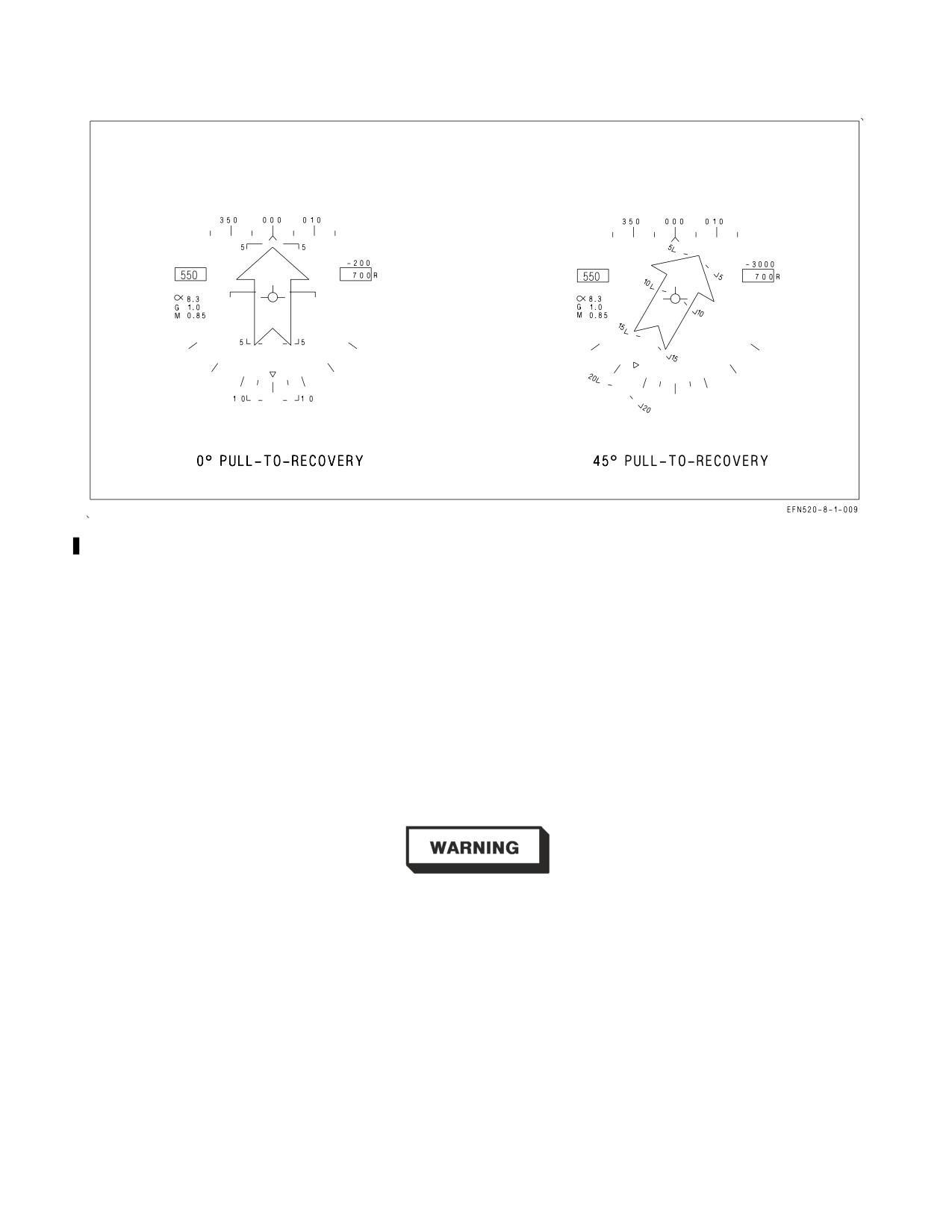
A1-F18EA-NFM-000
Figure 2-43. GPWS HUD Roll Warning Cues
2.17.5.4.1 GPWS HUD Recovery Arrow. The GPWS visual warning cue is a steady arrow located in
the center of the HUD. See figure 2-43. The HUD recovery arrow is always perpendicular to the horizon
and points in the direction of pull required for recovery. The HUD recovery cue is displayed
simultaneously with all voice warnings except CHECK GEAR. The HUD recovery arrow remains
displayed until GPWS calculates that a CFIT condition no longer exists.
2.17.5.4.2 GPWS Voice Commands. Refer to figure 2-44 for GPWS aural warning cues.
Voice commands automatically transition to the appropriate command for the current stage of
recovery (e.g., ROLL OUT transitions to PULL UP when AOB becomes less than 45°). The voice
commands are terminated when the appropriate recovery maneuver is initiated (e.g., a PULL UP is
initiated within 0.5 g of the GPWS calculated target-g).
• In addition to following the voice commands, additional pilot action
may be required to avoid an unrecoverable situation (e.g., aft stick
with a POWER call or power addition/subtraction with a PULL UP
call.)
• GPWS voice alerts are delayed if other voice alerts are currently being
transmitted.
I-2-138
ORIGINAL
A1-F18EA-NFM-000
GPWS Warning
Aural Cue
Repetition Rate
Condition
Excessive bank angle
″ROLL LEFT (RIGHT), ROLL LEFT (RIGHT)″
2 seconds
Excessive take-off
″POWER, POWER″
2 seconds
sink rate
Excessive landing
″POWER, POWER″
2 seconds
sink rate
Gear-up landing
″CHECK GEAR″
8 seconds
ALDR or floor
″POWER, POWER″ for airspeed <210 KCAS and
2 seconds
altitude
AOB ≤45°
″ROLL LEFT (RIGHT), ROLL LEFT (RIGHT)″
2 seconds
for AOB >45°
″PULL UP, PULL UP″ for all other flight
2 seconds
conditions
Figure 2-44. GPWS Aural Cues
2.17.5.5 Areas of Limited CFIT Protection. Areas where CFIT protection is considered limited are
as follows:
1. In the COAST mode (5 to 120 seconds outside the valid RALT envelope).
2. Over rising terrain of greater than 2° slope (GPWS is inhibited to prevent nuisance warnings).
3. Within the GPWS LAT envelope where allowable pilot reaction times have been reduced (±30°
AOB, 0 to 30° dive, 450 to 560 KCAS).
4. Below 150 feet AGL in the landing phase (less than 200 KCAS) where warnings are designed only
to prevent hard landings.
At certain high speed, high gross weight conditions, overriding the
g-limiter may be required for recovery from dives greater than 50° and
will likely be required for dives between 10 and 25°.
I-2-139
ORIGINAL
A1-F18EA-NFM-000
2.17.5.6 Areas of No CFIT Protection. Areas of no protection are as follows:
1. Loss of air data or RALT, INS, or MC1 failed or off (non-AMCD aircraft), or either MC1 or MC2
failed or off (AMCD aircraft).
2. Less than 6 seconds after WonW.
3. Less than 5 seconds or greater than 120 seconds outside the valid RALT envelope.
4. Transonic flight (0.95 to Mach 1.04) outside the valid RALT envelope.
5. For 1.5 seconds after a break X is displayed.
6. After a waveoff until exceeding 1,000 fpm for 5 seconds.
7. Dives greater than 50° after 2 minutes above 5,000 feet AGL.
2.18 INSTRUMENTS
Refer to foldout section for cockpit instrument panel illustration. For instruments that are an
integral part of an aircraft system, refer to that system description in this section.
2.18.1 Standby Attitude Reference Indicator. The standby attitude reference indicator is a self-
contained electrically driven gyro-horizon type instrument. It is normally powered by the right 115
volts ac bus. If this power fails it is automatically powered by an inverter operating off the essential 28
volts dc bus. An OFF flag appears if both power sources fail or the gyro is caged. During caging the gyro
initially cages to 4° pitch and 0° roll regardless of aircraft attitude. After 3 to 5 minutes, the indicator
reads 0° pitch and 0° roll. Power should be applied for at least 1 minute before caging. The indicator
displays roll through 360°. Pitch display is limited by mechanical stops at approximately 90° climb and
80° dive. As the aircraft reaches either stop, the gyro tumbles 180° in roll. A needle and ball are at the
bottom of the instrument. A one needle width turn is 90° per minute.
2.18.2 Standby Airspeed Indicator. The standby airspeed indicator displays airspeed from 60 to 850
KIAS. It operates directly from left pitot and static pressure.
2.18.3 Standby Altimeter. The standby altimeter is a counter-pointer type. The counter drum
indicates altitude in thousands of feet from 00 to 99. The long pointer indicates altitude in 50-foot
increments with one full revolution each 1,000 feet. A knob and window permit setting the altimeter
I-2-140
ORIGINAL
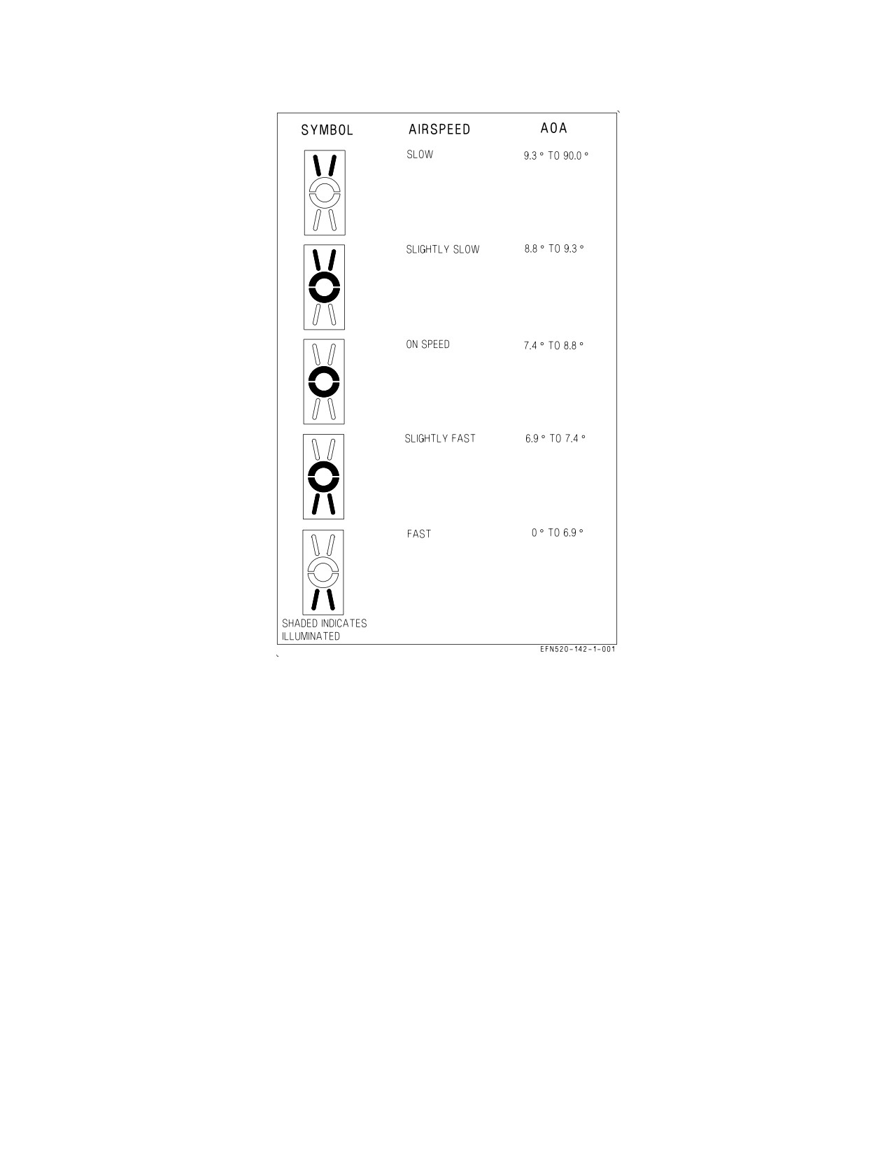
A1-F18EA-NFM-000
Figure 2-45. Angle of Attack Indexer
to the desired barometric setting. This setting is also used by the flight control computers. The standby
altimeter operates directly from left static pressure.
2.18.4 Standby Rate of Climb Indicator. The standby rate of climb indicator displays vertical speed
on a scale from 0 to ±6,000 fpm and operates directly from left static pressure.
2.18.5 Standby Magnetic Compass. A conventional aircraft magnetic compass is mounted on the
right windshield arch in the front cockpit and in the rear cockpit in Lots 21 thru 25.
2.18.6 Angle Of Attack Indexer. The angle of attack indexer is mounted to the left of the HUD. It
displays approach angle of attack (AOA) with lighted symbols; corresponding AOA indications are
shown on the HUD (see figure 2-45). The indexer operates with the landing gear down and locked and
weight off the gear. The lighted symbol(s) flash if the arresting hook is up and the hook bypass switch,
on the left vertical panel, is in CARRIER. The symbols will not flash with the arresting hook up and
the hook bypass switch in FIELD. The switch is solenoid held to FIELD and automatically goes to
CARRIER when the arresting hook is lowered or aircraft power is removed. The AOA indexer knob on
the HUD controls dimming of the symbols. All symbols light when the lights test switch on the interior
lights control panel is held to TEST.
I-2-141
ORIGINAL
A1-F18EA-NFM-000
2.19 AVIONICS SUBSYSTEM
The avionics subsystem combines the integration and automation needed for operability with the
redundancy required to ensure flight safety and mission success. Key features of the system include
highly integrated controls and displays, inertial navigation set with carrier alignment capability, and
extensive built in test capability. The avionics subsystems operate under the control of two mission
computers with primary data transfer between the mission computers and the other avionics
equipment via the mux buses.
2.19.1 Mission Computer System. The mission computer system consists of two digital computers
(MC1 and MC2) which are high speed, stored program, programmable, general purpose computers
with core memory. Computer de-selection is made with the MC switch on the MC/HYD ISOL panel.
With non-AMCD aircraft, the two mission computers interconnect with the primary avionics
equipment on the avionics multiplex (mux) buses. MC1, referred to as the navigation computer,
performs processing for navigation, control/display management, aircraft built in test (BIT), status
monitoring operations and backup for MC2. MC2, referred to as the weapon delivery computer,
performs processing for air-to-air combat, air-to-ground attack, and tactical control/display.
There are six avionics mux bus channels with redundant paths (X and Y) for each channel.
The mission computer:
1. Computes and controls the data sent to the cockpit displays,
2. Computes missile launch and weapon release commands,
3. Provides mode control and options for various avionics systems,
4. Generates BIT initiate signals to and equipment operational status from various avionics
systems.
With AMCD aircraft, the front and rear DDIs are driven directly by the MC over a high speed
interface bus, not by avionics mux bus commands. The HUD is driven directly by redundant
connection to either MC. MC1 drives the front and rear LDDIs and HUD while MC2 drives the front
and rear RDDIs and HUD. When an MC is off or non-functional, the displays driven by that MC show
a green square in the center of the display. Each MC provides the same level of functionality in the
single MC backup mode of operation.
On AMCD aircraft, with both MCs inoperative and the left generator operative, the SDC provides
a limited HUD format on the front MPCD/UFCD, prevents the FADEC and ECS controller from going
into default mode operation, and provides left/right ATS cautions when necessary. See Chapter 25
Backup/Degraded Operations for a description of SDC Backup Mode.
AMCD II mission computers are used on aircraft with the aft cockpit 8 x 10 display installed. The
8 x 10 display receives its primary signal through MC2, and is inoperative with computers prior to
AMCDII. The AMCD II computer provides digital video color capability to the 8 x 10 display via the
Fiber Channel Network Switch (FCNS) and High Speed Video Network (HSVN).
The computers receive inputs for navigational data and steering command computations from the
inertial navigation system, electronic flight control system, multipurpose display group, TACAN, and
backup attitude and the navigation system. The computers control display symbology and information
presented to the pilot by the multipurpose display group.
I-2-142
ORIGINAL
A1-F18EA-NFM-000
2.19.1.1 MC Switch. The MC switch, located on the outboard edge of the aft left console, is used to
manually turn OFF either of the two mission computers, MC1 or MC2.
1 OFF Removes power to MC1.
NORM Both MC1 and MC2 are powered with ac electrical power available.
2 OFF Removes power to MC2.
On non-AMCD aircraft with WonW, both engines will spool up from ground idle to flight idle, if
power is removed from MC1 (MC1 switch in 1 OFF).
2.19.1.2 Mission Data Entry. Mission data (date and flight number) can be manually loaded into the
mission computer for data recorder documentation. Data is entered by performing the following:
1. On the DDI - Press MENU, MUMI, then ID.
2. On the UFCD - Enter Julian Date (DATE).
3. On the UFCD - Enter Flight Information (FLT).
Mission data can be manually loaded into the mission computer through the Memory Unit Mission
Initialization (MUMI) display or automatically loaded into the mission computer through the Data
Storage Set (DSS). The DSS consists of the Memory Unit (MU) and the Memory Unit Mount (MUM)
and provides memory storage for aircraft parameters, maintenance data, and avionics initialization
data. The DSS receives, stores, retrieves, and transmits data with the mission computer.
2.19.1.2.1 Mission Initialization. The MU provides the capability to load the following mission
initialization files: HARM, RADAR, MU ID, TACAN, WYPT/OAP, Combined Interrogator Tran-
sponder (CIT), Sequential Steering (S/S), data link/ID, Overlay Controlled Stores (OCS), bomb wind
data, and ALR-67 display resets. The S/S file can have a 15 point sequence consisting of Geographic
Reference Points (GEOREF), GPS waypoints, and almanac data initialization files. Loading is done at
aircraft power up or when MUX communication is lost for more than 1 second and regained. If MUX
communication is not regained, a MU LOAD caution is displayed and an AV MUX error message is
displayed on the MUMI display. Manual loading may be done using the MUMI display.
2.19.1.2.2 MUMI - Memory Unit Mission Initialization Format. The MUMI format (see figure 2-46)
is accessible from the SUPT MENU and with WonW provides a visual indication of mission
initialization files loaded from the MU. If the MU directory indicates that no user files are present, the
MU ID displays NO IDENT. When the MU directory indicates a user file is present, MC1 displays the
option. When the option is selected and the file is being read by MC1, the option is boxed. If the read
is successful, the file is loaded and the option is unboxed. When a file is present and errors have
resulted from reading the file, the following occurs:
1. The MU ID displays NO IDENT.
2. The applicable load error is displayed (HARM, RDR, TCN, WYPT, S/S, OCS, GPS WYPT, GPS
ALM, ALR 67, WIND, DL13, or CIT).
3. MC1 sends the appropriate maintenance code to the SDC.
I-2-143
ORIGINAL
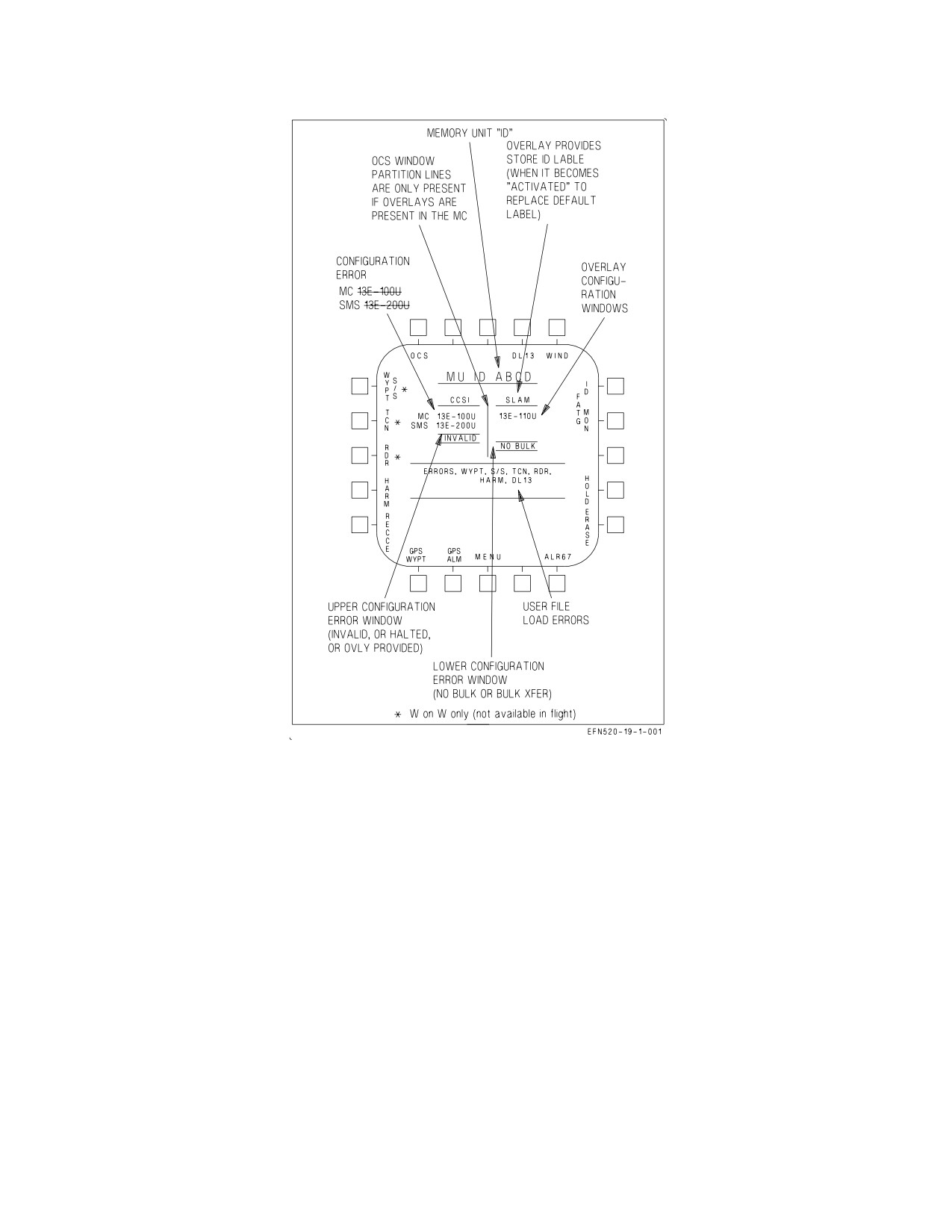
A1-F18EA-NFM-000
Figure 2-46. MUMI Display
4. If WonW, an MU LOAD caution is displayed on the DDI.
2.19.1.2.3 CRYPTO Switch. Setting the intercommunications amplifier control CRYPTO switch to
the ZERO position sends an erase signal to the MU. This causes the MU to erase all data stored
between predetermined memory locations.
2.19.1.2.4 Erase and Hold Data. The erase controller (EC) within MC1 provides the capability to
automatically or manually erase, or inhibit erasing, of classified data contained in the MU, SMS, MC1,
and MC2.
NOTE
With AMCD aircraft, during an ERASE, the DDI controlled by the
MC undergoing the erase will flash STANDBY, then briefly display a
green square, then flash STANDBY until the erase is complete.
When the EC determines classified mission initialization files have been read from the MU, the EC
classified data management system is activated. When activated, MC1:
I-2-144
ORIGINAL
A1-F18EA-NFM-000
1. Displays the HOLD and ERASE options on the MUMI display.
2. Displays the CDATA advisory.
3. Sends applicable maintenance code(s) to the SDC.
2.19.1.2.5 Automatic Erase. The MU, SMS, MC1, and MC2 automatically erase classified data
when all of the following criteria are met.
1. Airspeed is less than 80 KCAS.
2. Left and right engine THA less than 29°.
3. Transition from WoffW to WonW.
4. Pilot does not select erase inhibit (HOLD) or MC SUSPEND options.
NOTE
Automatic erase can be inhibited by selecting the HOLD pushbutton
option.
5. HOLD boxed with MU displayed prevents automatic erase of the MU.
6. HOLD boxed with ALL displayed prevents automatic erase of all units (MU, armament
computer, MC1, and MC2).
The EC commands the MU and the armament computer, then MC1 and MC2 to erase. The MC
ERASE IN XX SEC countdown timer starts (60 seconds). During the countdown, an MC SUSPEND
pushbutton option is displayed. The MC SUSPEND option may be toggled between boxed (selected)
and unboxed (deselected). When the timer reaches zero and the MU and armament computer have
finished erasing, the decision to continue erasing the remainder of MC1 and MC2 depends on the MC
SUSPEND option being deselected (unboxed); when deselected, the remaining erase of MC2 and MC1
is completed.
NOTE
With AMCD aircraft, during an ERASE, the DDI controlled by the
MC undergoing the erase will flash STANDBY, then briefly display a
green square, then flash STANDBY until the erase is complete.
Automatic erase is also initiated by pilot ejection. The state of the HOLD options is ignored during
pilot ejection.
2.19.1.2.6 Manual Erase. Manual erase is a two pushbutton process and is initiated by pressing the
ERASE pushbutton on the MUMI display. When the ERASE pushbutton is pressed, the option to
proceed with the erasure (ERASE) and the option to cancel the erase (CNX) replaces the HOLD and
ERASE options. Selecting the second ERASE option initiates erasure. While erase is in progress,
ERASE is boxed and erasing proceeds the same as automatic erase. When erasing is complete, the
ERASE pushbutton unboxes. While erase is in progress one of the following is displayed on the MUMI
display:
I-2-145
ORIGINAL
A1-F18EA-NFM-000
1. ERASING - erasing of unit is in progress.
2. COMPLETE - erasing of unit is complete.
3. FAILED - unit failed to erase.
NOTE
With AMCD aircraft, during an ERASE, the DDI controlled by the
MC undergoing the erase will flash STANDBY, then briefly display a
green square, then flash STANDBY until the erase is complete.
When erase fails, the MC1 retains the MUMI ERASE and HOLD pushbutton options and displays
the ERASE FAIL caution on the DDI. When erasing is complete, MC1 removes the ERASE, HOLD,
and MC SUSPEND pushbutton options from the MUMI display, removes the CDATA advisory from
the display, and resets the applicable maintenance code(s).
2.19.1.2.7 Backup Erase Controller. If MC1 fails, backup erase capability is provided by MC2 by
providing an ERASE option on the HSI format. When the ERASE pushbutton is depressed, the option
to proceed with the erasure (ERASE) and the option to cancel the erasure (CNX) are provided.
Selecting the second ERASE option initiates erasure. While ERASE is in progress, the ERASE option
is boxed; however, additional cuing is not provided. In backup mode, pilot ejection is the only
automatic erase provided. With AMCD aircraft, the MUMI display for the MC being erased disappears
while the erase is in progress.
2.19.2 Master Modes. There are three master modes of operation: navigation (NAV), air-to-air
(A/A), and air-to-ground (A/G). Controls, displays, and the avionics equipment operation are tailored
as a function of the master mode selected. The navigation master mode is entered automatically when
power is applied to the aircraft, when the air-to-air or air-to-ground modes are deselected, when the
landing gear is lowered, when the SPIN mode activates, or when the aircraft has WonW and the THA
is greater than 27°. The A/A master mode is entered either by pressing the A/A master mode button
alongside the left DDI or by selecting an A/A weapon with the A/A weapon select switch on the control
stick. The A/G master mode is selected by pressing the A/G master mode button. The selection is
performed by the stores management set (SMS), and the SMS identifies the selected master mode to
the mission computer.
2.19.2.1 Steering Information. The sources of steering information available in the NAV master
mode are waypoint, TACAN, instrument landing system, and data link. The data link modes available
in the NAV master mode are vector and automatic carrier landing. TACAN and waypoint steering are
mutually exclusive; selecting one automatically deselects the other. Data link, ILS, and TACAN (or
waypoint) steering can be provided simultaneously. The ACL mode is selectable only in the NAV
master mode and the vector mode is available in all master modes. Steering information is used by the
Automatic Flight Control System to provide coupled steering options.
2.19.3 Cockpit Controls and Displays. The cockpit controls and displays which are used for
navigation operation are on the multipurpose display group.
2.19.4 Multipurpose Display Group. The multipurpose display group consists of the right and left
digital display indicators (DDIs), the multipurpose color display (MPCD), 8 x 10 display, the digital
map set (DMS), the head-up display (HUD), the CRS (course) set switch, the up front control display
(UFCD) and the HDG/TK (heading/ground track) set switch. The multipurpose display group
I-2-146
ORIGINAL
A1-F18EA-NFM-000
presents navigation, attack, and aircraft attitude displays to the pilot. The multipurpose display group
converts information received from the mission computer system to symbology for display on the DDIs,
the MPCD, the UFCD, and the HUD. The HUD camera records the outside world and HUD
symbology. The left and right DDIs, 8 x 10 display and the MPCD contain pushbuttons for display
selection and selection of various equipment operating modes. The UFCD is an active matrix liquid
crystal display with an infrared (IR) touchscreen for operator inputs. Refer to Part VII for the
operation of each component.
2.19.4.1 CRS Set Switch. The course set switch, located on the main instrument panel on the video
record panel, manually sets the desired course on the HSI display.
2.19.4.2 HDG/TK Set Switch. The heading/ground track set switch located on the main instrument
panel on the video record panel, manually sets the heading marker on the desired heading/ground track
on the HSI display.
2.19.4.3 DDIs. The left and right DDI (LDDI/RDDI) are physically and functionally interchange-
able, giving the ability to display desired information on either indicator. With non-AMCD aircraft, the
DDIs also provide symbology to the HUD. The left indicator is used primarily for stores status, built
in test status, engine monitor, caution, and advisory displays. The right indicator is normally used for
radar and weapon video displays.
(Non-AMCD aircraft) The DDIs are NVG compatible and display three colors (red, yellow, and
green) for stroke information. A monochrome version of the digital map can be selected on the left DDI.
Either DDI can provide raster generation for the HUD.
NOTE
It is possible that a transient condition may cause the displays to
blank or provide an erroneous display on the left or right DDI, or
HUD. The problem may be cleared by manually cycling the power to
the left or right DDI.
(AMCD Aircraft) The DDIs have full color capability in all display modes and are NVG compatible.
2.19.4.3.1 Brightness Selector Knob - Non-AMCD Aircraft. Placing this rotary knob to OFF
prevents the DDI from operating. Placing the knob to NIGHT provides a lower brightness control
range and no automatic contrast control. Turning the knob to DAY provides a higher brightness
control range.
2.19.4.3.2 BRT Control Knob - Non-AMCD Aircraft. This knob varies the intensity of the DDI
presentation.
2.19.4.3.3 Brightness Knob - AMCD Aircraft. Placing this rotary knob to OFF prevents the DDI
from operating. When turned on, rotating the knob clockwise increases display brightness, while
rotating the knob counterclockwise decreases display brightness.
2.19.4.3.4 GAIN Control - AMCD Aircraft. This three-position rocker switch affects the existing
gray-scale, shifting the backg1round brightness up or down, with no impact on displayed symbology.
The center position is off, while the up arrow increases backg1round brightness and the down arrow
decreases backg1round brightness. The up and down arrows have momentary and scroll functionality,
I-2-147
ORIGINAL
A1-F18EA-NFM-000
depending on how long they are held. Current values are temporarily displayed when switches are
pressed.
2.19.4.3.5 CONT Control. This knob (non-AMCD aircraft), or three-position rocker switch (AMCD
aircraft), varies the contrast between symbology and the dark backg1round on any level of brightness.
With AMCD aircraft, when the contrast rocker is pressed, a graphical and numeric representation of
the current setting is momentarily displayed on the DDI.
2.19.4.3.6 DDI Pushbuttons. There are 20 pushbuttons on each DDI which are used to select the
function and the mode for proper indicator display.
2.19.4.3.7 MENU Formats. There are two MENU formats (figure 2-47), TAC (tactical) and SUPT
(support) through which display selections can be made. The two menu formats can appear on either
the DDI, the UFCD, 8 x 10 display or MPCD.
The TAC MENU is indicated by the word TAC appearing just above the MENU option. The TAC
MENU is selected by actuating the MENU option on any format other than the TAC MENU format.
The SUPT MENU is indicated by the word SUPT appearing just above the MENU option. The SUPT
MENU is selected by actuating the MENU option on the TAC MENU. With MC OFP H2E AND UP,
the current time of day, consisting of two minute digits and two second digits appear in place of the
MENU legend (cold start default). Time of day is also turned on/off with the TISM option on the
Engine Format. MENU pushbutton functionality is unchanged.
The TAC MENU allows selection of the following formats: AZ/EL, HUD, RDR ATTK, STORES,
FLIR, NFLIR, DL13, HARM, A/G WPN, JSOW, SA, IMAGE, CAS, EW, and TGT DATA. The SUPT
MENU allows selection of the following formats: ADI, HSI, HMD, NETS, GPS, MIDS, ROE/IFF
PROG, BIT, CTT, MUMI, CHKLST, ENG, FCS, UFC BU, FPAS, and FUEL.
Some of the options on the MENU formats are conditional and are not always displayed. NFLR,
FLIR, LST, and CAM are listed only if the equipment is communicating with the mission computer.
HARM DSPLY is displayed when HARM is on board and CLC communicating. A/G missile display
(WEDL DSPLY, MAV DSPLY, etc.) is displayed when the MC has determined from the armament
control processor set that a weapon station has been selected which contains one of these weapons.
In Non-AMCD Aircraft, if the navigation computer (MC1) is not on, only HSI is displayed on the
SUPT menu. If the weapon delivery computer (MC2) is not on, the SUPT menu remains unchanged
and the TAC menu does not display the STORES, FLIR/LST/CAM or NFLR, AWW-13, HARM, or
A/G displays. If both mission computers are off or not communicating with the display, the DDI,
MPCD, and UFCD display only a flashing STANDBY in the center of the screen.
In AMCD Aircraft, if either mission computer is off or failed (MC Backup Mode), the options
available on the displays are the same regardless of which computer is failed. MC1 is no longer referred
to as the navigation computer and MC2 is no longer referred to as the weapons computer. If MC1 is
failed or not communicating, the left DDIs in both cockpits will either flash STANDBY or have a green
square present in the middle of the displays. If MC2 is failed or not communicating with the display,
the right DDIs in both cockpits will either flash STANDBY or have a green square present in the
middle of the displays. The 8 x 10 display will not be capable of displaying format symbology or video.
The following options are available in MC Backup mode: HUD, EW, FCS, MIDS, MUMI, ENG, UFC
BU, FUEL, ADI, and HSI. If A/A master mode is selected, the RDR ATTK, SA, and AZ/EL formats
are available as well. No A/G displays are supported in MC Backup mode. If both mission computers
are off or failed, a backup HUD format (driven by the SDC) is displayed on the UFCD and MPCD in
the front cockpit.
I-2-148
ORIGINAL
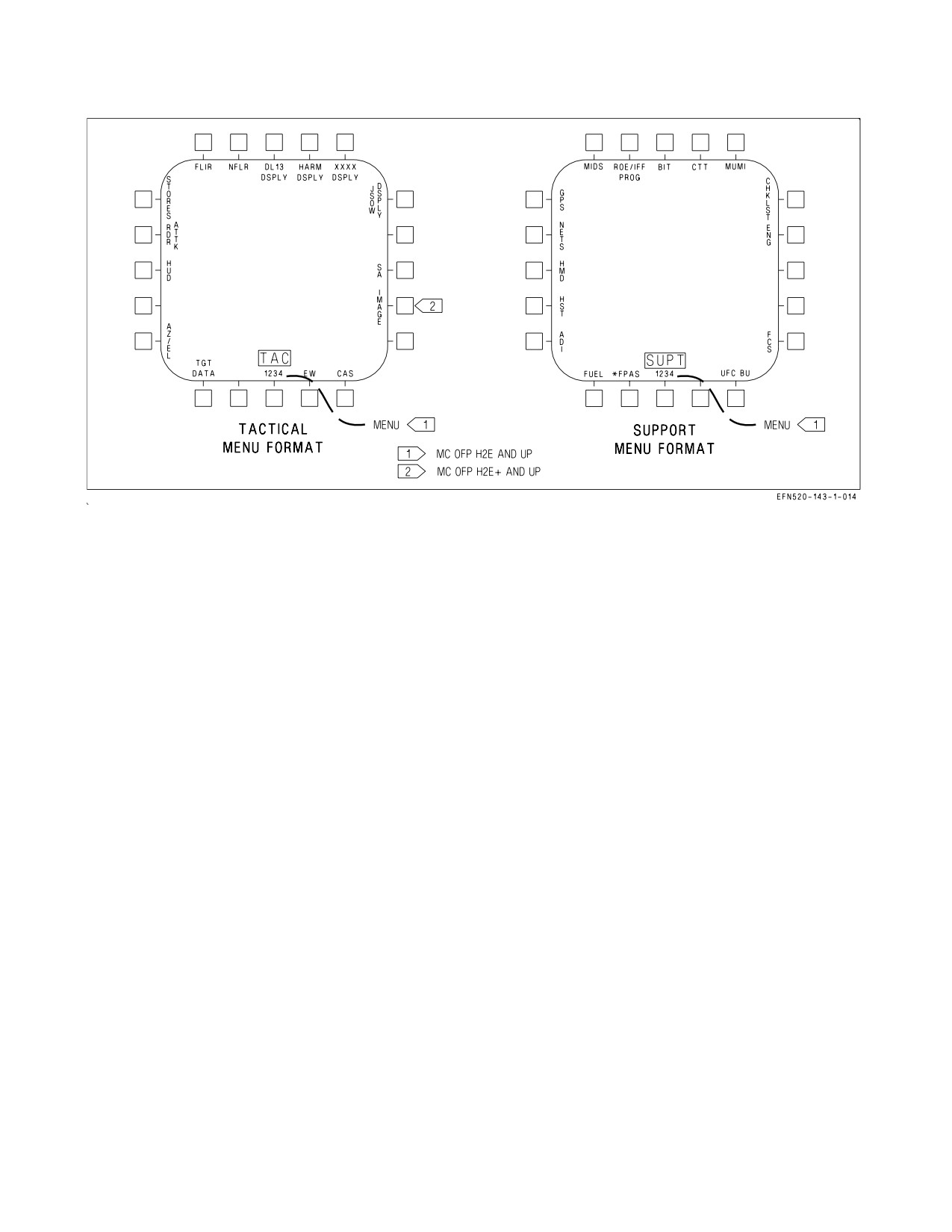
A1-F18EA-NFM-000
Figure 2-47. MENU Format
2.19.4.3.8 Electronic Attitude Display Indicator (EADI). The electronic attitude display indicator is
available for display on the left or right DDI as an alternative to the attitude display on the HUD
(figure 2-48). The EADI display is selected by selecting the ADI option on the SUPT MENU. The pitch
ladder is displayed in 10° increments. A small circle is displayed on the ball to represent the zenith and
a circle with an inscribed cross is displayed to represent the nadir. A turn indicator which displays FCS
yaw rate is provided below the ball. A standard rate turn (3°/second) is indicated when the lower box
is displaced so that it is under one of the end boxes.
Selecting the INS or STBY options at the bottom of the display determines the source of attitude
information used to generate the display. Upon power-up with WonW, the EADI attitude initializes to
STBY (STBY boxed), thus using the standby attitude reference indicator for attitude source
information. Selecting the INS option (INS boxed) uses attitude information provided by the INS.
Selection of INS or STBY on the EADI does not change the source of attitude data for the HUD.
Airspeed and altitude are displayed in boxes at the top left and right. Altitude source is displayed
to the right of the altitude box and the vertical velocity is displayed above the altitude box. When ILS
is selected the deviation needles are displayed in reference to the waterline symbol. The ILS needles
are yellow when COLOR is selected on the Attack display.
2.19.4.3.9 Shaped Attitude Display Indicator. When the ADI option is selected on the SUPT menu,
a shaped attitude display indicator is available on the MPCD, UFCD, or DDI and 8 x 10 display
(AMCD aircraft). The pitch ladder is displayed in 10° increments, with ±30° in pitch being displayed
when the gear is up. With the gear down, the pitch ladder is displayed in 5° increments with ±15° in
pitch being displayed. A turn indicator is provided below the ball. A standard rate turn (3°/second) is
indicated when the lower box is displaced so that it is under one of the end boxes.
On the MPCD and 8 x 10 display, the shaped ADI is black above the horizon to represent sky, and
green below the horizon to represent the ground. On the UFCD, the shaped ADI is unshaded above the
horizon (sky) and shaded green below the horizon (ground).
I-2-149
ORIGINAL
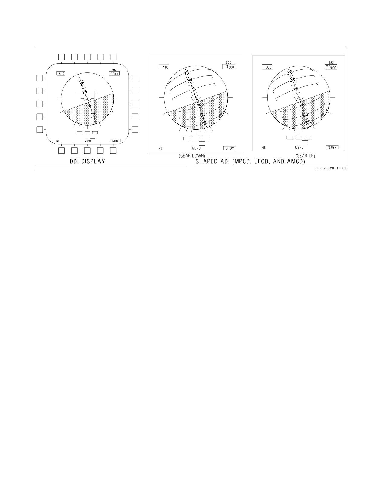
A1-F18EA-NFM-000
Figure 2-48. Electronic Attitude Display Indicator
Selecting the INS or STBY options at the bottom of the display determines the source of attitude
information used to generate the display. Upon power-up with WonW, the ADI attitude initializes to
STBY (STBY boxed), thus using the standby attitude reference indicator for attitude source
information. Selecting the INS option (INS boxed) uses attitude information provided by the INS.
Selection of INS or STBY on the ADI does not change the source of attitude data for the HUD.
Airspeed and altitude are displayed in boxes at the top, altitude source is displayed to the right of
the altitude box and vertical velocity is displayed above the altitude box. When ILS is selected the
deviation needles are displayed in reference to the waterline symbol. The ILS needles are yellow when
COLOR is selected on the attack display.
2.19.4.4 MPCD - Multipurpose Color Display. The MPCD is an NVG compatible digital display
capable of providing any MENU selectable format except the video on the A/G radar display (figure
2-50). The MPCD drives itself using information received on the MUX.
The BRT knob controls the overall video and symbology brightness and also acts as the power
control for the MPCD and UFCD; a detented OFF position at the extreme counterclockwise position.
The CONT knob adjusts the video contrast of the MPCD display. The day/night mode is controlled
by the day/night/NVG switch on the interior lights panel.
2.19.4.4.1 Standby Indication. A flashing STANDBY indication is provided in the center of the
display on initial power-up and when there is invalid mux communication with the MC. If the
STANDBY condition persists for a few seconds, cycling power to the MPCD may return the MPCD
and UFCD to normal operation.
2.19.4.4.2 Brightness and Contrast Controls. The brightness control is used to adjust the overall
brightness of the MPCD display surface, allowing symbology and video to be adjusted. The full
counterclockwise position of the brightness control knob shuts off power to both the MPCD and the
UFCD. Selecting ON powers both the MPCD and the UFCD.
The contrast control is used to adjust video contrast.
2.19.4.4.3 Symbology Rocker Switch. The symbology (SYM) brightness rocker switch is used to
adjust the brightness of the symbology without affecting the brightness of the MPCD video.
I-2-150
ORIGINAL
A1-F18EA-NFM-000
Symbology change feedback in provided in the left center of the display by a digit from 0 to 9. This
feedback is provided while the rocker switch is pressed and for 5 seconds after the rocker switch is
released.
2.19.4.4.4 DDI Formats on MPCD. Every display format is available on the L or R DDI. A/G radar
symbology and monochrome video is available on the MPCD. A/G video is not available.
2.19.4.4.5
MPCD Formats. With non-AMCD aircraft, if two different map formats are provided in
the front and rear cockpits, only one displays the map; the other provides only symbology. The priority
of the format which displays the map is HSI, followed by SA.
With AMCD aircraft, if two different formats are requesting MAP video underlay, only one displays
the video underlay; the other provides only symbology. MAP video display priority is determined by
two things: 1) which display surface is requesting the MAP underlay and 2) which format is requesting
the MAP underlay. Highest display surface priority is given to the MPCD followed by the DDIs. The
SA format is given the highest priority, followed by the HSI format, for formats requesting the MAP
underlay. Once the MAP is displayed for any format, (SA, HSI), any display surface with that same
format selected will also have the MAP underlay displayed. The MAP underlay is only supported on
the SA or HSI formats.
2.19.4.4.5A 8 x 10 Display. On aircraft LOT 26 AND UP, the 8 x 10 display replaces the aft MPCD.
The 8 x 10 display has a full color Active Matrix Liquid Crystal Display surface and 30 pushbuttons
used for operator inputs. Only 20 buttons are functional, and they duplicate the MPCD/DDI menu
layouts. The top row outboard buttons and top four buttons on each side are not used. The brightness
control switch adjusts the video brightness. The full counterclockwise position, a detented OFF
position, removes power from the 8 x 10 display and the aft cockpit UFCD. Two rocker switches
provide Gain and Contrast control. A numeric value displayed near the switches is used to adjust the
gain and/or contrast to a desired level. Pushbuttons are backlit, controlled by the INST PNL knob on
the aft cockpit interior lights panel. The following formats and related sublevel formats are available:
TAC Menu, SUPT Menu, HSI, EW, SA, TFLIR and BIT. Figure 2-49 shows symbology placement and
map coverage for the 8 x 10 display. See figure FO - 4, foldout section for aft cockpit arrangement with
the 8 x 10 display installed.
The 8 x 10 display is connected directly to MC2. The computer recognizes whether an 8 x 10 display
or an MPCD is installed and uses the corresponding software that matches the configuration at
startup. This affects the UFCD controls and functions in addition to the 8 x 10 display. When MC2 is
offline or during initialization, the 8 x 10 display does not show a format or process bezel inputs. A
flashing STANDBY indication is provided in the center of the 8 x 10 display when MC2 is not
communicating properly with the 8 x 10 display. A standby display pattern (approximately a 1- by
1-inch green square) is present when the Image Transfer Bus (ITB) has lost symbology, video, or a
combination, and the selected format is affected. When interface between MC2 and 8 x 10 display is
lost, only symbology is displayed (via ITB). There is no pushbutton feedback, video control, or BIT
reporting when interface is degraded. The day/night mode of the 8 x 10 display (and rear UFCD) is set
via the DAY/NITE/NVG switch on the forward cockpit interior lights panel through MC2.
In the Situational Awareness (SA) format, the cursor (captains bars) may be slewed over the entire
8 x 10 display surface. Because this area is larger than the DDIs/MPCD, if another display is showing
the same format and the cursor on the 8 x 10 display is slewed beyond the center area, the cursor on
the DDI/MPCD is limited. When this happens, the cursor on the DDI/MPCD displays flashes
continuously. When a SA format has DC priority assigned, the initial cursor position is determined by
the cockpit that initiates the slewing action.
I-2-151
ORIGINAL
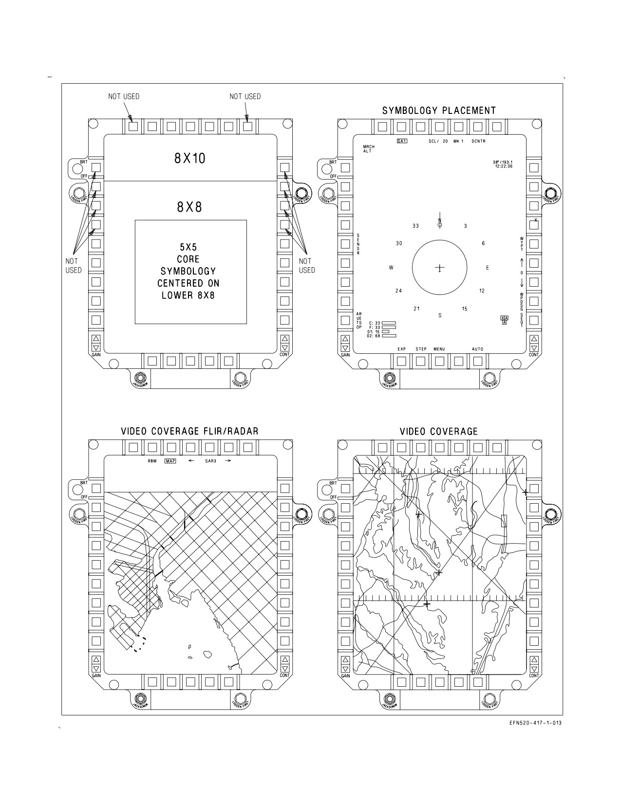
A1-F18EA-NFM-000
Figure 2-49. 8 x 10 Display
I-2-152
ORIGINAL
A1-F18EA-NFM-000
2.19.4.5 HSI Display Symbology. Basic HSI symbology such as the compass rose, ground track
pointer, lubber line (for magnetic heading), true airspeed readout, ADF bearing pointer, groundspeed
readout, and aircraft symbol are not described. These symbols are shown in figure 2-50.
Display format lines, just below the top row of pushbutton labels, indicate the formats being
displayed on the left, center, right and UFCD displays in both the cockpit (left side of HSI display) and
rear cockpit (right side of HSI display).
Radar target and GEOREF symbols are described in A1-F18EA-TAC-Series. The following
paragraphs describe unique navigation symbology. Refer to part VII for a description of how these
symbols are integrated with the navigation system:
1. Waypoint/OAP data. Data for the current steer to waypoint/OAP is displayed on the upper right
corner of the HSI. Waypoint/OAP data consists of bearing, range, and TTG (time-to-go) up to
8:59:59 based on distance and ground speed. When a waypoint/OAP or offset to the OAP is
designated (becomes a target), this data relates to the target. When a waypoint is a waypoint that
was transferred from the GPS, an ID code is displayed under the waypoint data.
2. TACAN data. TACAN data is displayed on the upper left corner of the HSI. TACAN data
consists of bearing, range (slant range), TTG (based on distance and present ground speed), and the
station identifier.
3. Waypoint/OAP symbology. Waypoint/OAP symbology consists of a waypoint/OAP symbol and a
bearing pointer and tail. The waypoint/OAP symbol indicates the position of the selected
waypoint/OAP relative to the aircraft symbol. The waypoint/OAP bearing pointer and tail are
displayed inside the compass rose and indicate bearing to the selected waypoint/OAP. Waypoint/
OAP symbology is displayed whether or not waypoint/OAP steering is selected. When the selected
waypoint/OAP is outside the HSI range scale, the waypoint/OAP symbol does not appear, but the
bearing pointer and tail appears. When a waypoint/OAP is designated, the waypoint/OAP symbol
and circle inside the pointer change to a diamond shape. The offset symbol appears when steering
is to an OAP. The offset symbol indicates the position of the offset relative to the OAP.
4. TACAN symbology. TACAN symbology consists of a TACAN symbol, and TACAN bearing
pointer and tail. The TACAN symbol indicates the position of the TACAN station relative to the
aircraft symbol. The TACAN bearing pointer and tail are located outside of the compass rose and
indicate bearing to the TACAN station. When the TACAN station is outside the HSI range scale, the
TACAN symbol does not appear but the bearing pointer and tail appear. When TACAN range
becomes invalid the TACAN symbol is not displayed.
NOTE
TACAN symbology displayed inside of the compass rose is filtered to
prevent excessive movement of TACAN symbols due to RF
interference. However, the ″fly−to″ needle displayed in the HUD with
TACAN steering selected is not filtered and represents the raw data
received by the TACAN. As a result, for brief periods of time, the
HUD and HSI may display conflicting information regarding aircraft
position with respect to the selected TACAN course line. Aircrew
should use HUD displayed TACAN information when conducting
TACAN approaches.
I-2-153
ORIGINAL
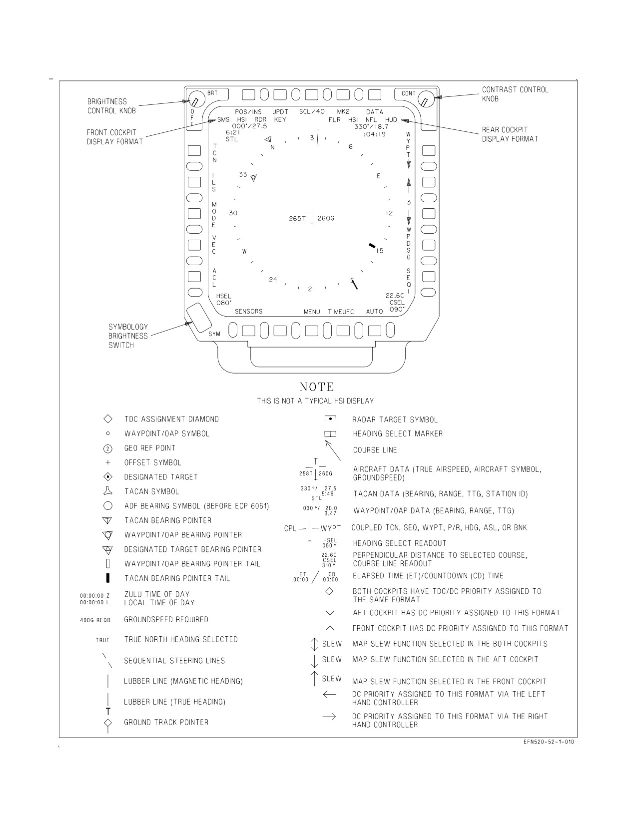
A1-F18EA-NFM-000
Figure 2-50. MPCD Controls and HSI Symbology
I-2-154
ORIGINAL
A1-F18EA-NFM-000
5. Heading select/ground select marker and readout. The heading select/ground select marker is
maneuvered along the periphery of the compass rose using the HDG/TK switch. The digital readout
of the selected heading is located on the lower left corner of the HSI. The heading select/ground
select marker and digital readout are part of the heading select/ground track select mode of the
autopilot.
Course line arrow and readout. The course line arrow indicates the selected course to the
waypoint/OAP or TACAN station. The course is selected using the CRS switch. The digital readout
of the selected course is displayed on the lower right corner of the HSI. The course line arrow is not
displayed when TACAN range is invalid.
6. TDC assignment symbol. The TDC assignment diamond is displayed on the upper right corner
of the HSI. This symbol indicates that the TDC is assigned to the HSI. The TDC assignment
diamond indicates control is assigned to both cockpits. Other symbols indicate cockpit (d) or rear
cockpit (e) TDC control and SLEW control. SLEW is done by actuating the sensor control switch
AFT while in the NAV or A/G master mode. The word SLEW is displayed in the TDC assignment
diamond position when the SLEW option is active.
7. Coupled steering symbology. CPL and the source of the steering information is displayed on
either side of the aircraft symbol in the center of the HSI display whenever the flight control system
is coupled in azimuth to a steering source. Steering source can be WYPT, TCN, or SEQ#. The couple
cue flashes for 10 seconds and is removed if the steering signal is lost or becomes invalid.
8. Sequential steering lines. The sequential steering lines are displayed when a sequence is entered
and when one of the sequence options (SEQ1, SEQ2, SEQ3, or SEQL) is boxed. The sequential
steering lines are available for display in all HSI modes and range scales. Sequential steering lines
are not displayed at power up with WonW and are removed when: magnetic heading is invalid,
aircraft position is invalid, or map slew is selected.
9. Time of day. Zulu time of day (ZTOD) or local time of day (LTOD) are displayed on the lower left
corner of the HSI. For aircraft that pass the FIRAMS real time clock power up BIT, ZTOD does not
need to be entered. For aircraft that do not pass the FIRAMS real time clock power up BIT, ZTOD
must be entered.
10. Groundspeed required. Groundspeed required appears below the current groundspeed readout.
Groundspeed required indicates the groundspeed required to a target based on entered ZTOD, time
on target (TOT), and the target.
11. Elapsed time (ET)/countdown (CD) time. ET and CD time are displayed on the lower right
corner of the HSI, however, only one of the timers can be displayed at a time. ET or CD timer must
be selected to be displayed. ET initializes to zero minutes and seconds and CD time initializes to six
minutes and zero seconds.
12. Aircraft heading. Aircraft heading is indicated on the compass rose. Aircraft heading and bearing
data can be selected as either magnetic or true. With true heading selected, the letter T appears
below the lubber line and the word TRUE appears below the selected scale readout. There is no
indication when magnetic heading is selected.
I-2-155
ORIGINAL

A1-F18EA-NFM-000
Figure 2-51. HUD Controls
2.19.4.6 HUD - Head-Up Display. The HUD is on the center main instrument panel. The HUD is
used as the primary flight instrument, weapon status, and weapon delivery display for the aircraft
under all conditions. (Non-AMCD aircraft) The HUD receives attack, navigation, situation, and
steering control information from the left or right DDI symbol generators (under mission computer
control) and projects symbology on the combining glass for head-up viewing. (AMCD aircraft) The
HUD receives all symbology from MC1 or MC2. The HUD is electrically interfaced with the UFCD.
The HUD has NVG compatible raster display capability to allow it to display NFLR video. The
controls for the HUD are below the UFCD and are described in the following paragraphs. See figure
2-51.
2.19.4.6.1 HUD Symbology Reject Switch. The HUD reject switch is located on the HUD control
panel on the center main instrument panel. This switch is used to control the amount of symbology
displayed on the HUD.
NORM Displays full HUD symbology.
REJ 1
Removes the Mach, g, and peak-g indications, the bank angle scale and pointer, the air-
speed and altitude boxes, energy caret (landing gear down), and the ground speed
required cue.
REJ 2
Removes REJ 1 symbology and the heading scale, current heading caret, command
heading marker, NAV/TCN range, and the ET, CD, LTOD or ZTOD timer.
2.19.4.6.2 HUD Symbology BRT Control Knob. This knob is used to turn on the HUD and then
varies the display intensity.
2.19.4.6.3 HUD Symbology Brightness Selector Switch. This is a two-position toggle switch with
positions of DAY and NIGHT. Placing the switch to DAY provides maximum symbol brightness in
conjunction with the HUD symbology brightness control. With the switch set to NIGHT, a reduced
symbol brightness is provided in conjunction with the HUD symbology brightness control.
2.19.4.6.4 Black Level Control Knob. The black level control knob, located on the HUD control
panel, adjusts the NFLR video plus or minus ½ a shade of gray per increment when rotated.
I-2-156
ORIGINAL
A1-F18EA-NFM-000
2.19.4.6.5 HUD Video Control Switch. The video control switch, located on the HUD control panel,
enables NFLR video display on the HUD with selectable polarity (white hot/black hot).
W/B Selects white hot/black hot polarity.
VID
Displays NFLR video in the HUD, if available.
OFF NFLR video off.
2.19.4.6.6 BAL Control Knob. The balance control, located on the HUD control panel, adjusts the
stroke brightness relative to the raster brightness. Rotating the switch from 12 o’clock towards the VID
position holds the brightness of the video (as set by the brightness control switch) and reduces the
brightness of the stroke symbology. The opposite is true when rotating the switch toward the SYM
position.
2.19.4.6.7 AOA Indexer Control Knob. This knob controls the brightness of the indexer lights.
2.19.4.6.8 ALT Selector Switch. The ALT selector switch, located on the HUD control panel, is used
to select the primary altitude source for display on the HUD and for use in the mission computer
(weapon systems calculations).
BARO Selects barometric altitude.
RDR Selects radar altitude.
2.19.4.6.9 ATT Selector Switch. The ATT selector switch, located on the HUD control panel, is used
to select the primary attitude source used for display in the HUD and in MC and FCC computations.
INS
Functions identically to the AUTO position.
AUTO Selects filtered INS data as the primary attitude source. The INS automatically reverts
to gyro mode, using unfiltered data if its processor fails. The MC automatically selects
the standby attitude reference indicator for attitude information if the INS fails com-
pletely.
STBY Selects the standby attitude reference indicator. The FCCs no longer use INS data and
the HIAOA advisory is displayed.
2.19.4.6.10 HUD Symbology. The following paragraphs describe HUD symbology as related to basic
navigation, steering (direct, great circle, courseline, and ILS), navigation target designation, advisories
and landing, see figure 2-52. Refer to part VII for a description of how these symbols are integrated into
the navigation system. Also, refer to section VII for unique ACL data link symbology. Refer to
A1-F18EA-TAC-Series, for symbology concerning the A/A and A/G master modes, weapons, RWR and
the data link vector mode.
1. Heading. The aircraft magnetic/true heading is indicated by the moving 30° heading scale. The
actual aircraft heading is directly above the caret/T symbol. The moving heading scale provides
trend information during turns. As the aircraft turns right, the scale moves from right to left.
Magnetic or true heading may be selected. Magnetic heading is indicated by a caret below the
heading scale. True heading selection is indicated by a T appearing below the current heading.
I-2-157
ORIGINAL
A1-F18EA-NFM-000
2. Airspeed. Calibrated airspeed from the FCC is provided in the box on the left side of the HUD.
The tops of the airspeed and altitude boxes are positioned at the aircraft waterline, which is 4° up
from the optical center of the HUD.
HUD airspeed should normally read less than 50 knots while sitting still
on the ground. A reading of more than 50 knots on the ground may
indicate an Air Data failure.
3. Altitude. The altitude presented in the box on the right side of the HUD may be either barometric
altitude or radar altitude depending on the setting of the altitude switch on the HUD control panel.
When the altitude switch is in the BARO position, barometric altitude is displayed. When the
altitude switch is in the RDR position, radar altitude is displayed and is identified by an R next to
the altitude. If the radar altitude is invalid, barometric altitude is displayed and a B next to the
altitude flashes to indicate that barometric altitude is being displayed rather than radar altitude. An
X displayed next to the barometric altitude indicates that the altitude value may be inaccurate. The
ten thousand and thousand digits are 150% size numbers. The hundred, ten, and unit digits are
120% size numbers, except that below 1,000 feet they are 150% size.
4. Barometric setting. The barometric setting used by the air data function in the FCC is the value
set in the standby altimeter. When the barometer setting is changed on the standby altimeter, the
barometric setting is presented below the altitude on the HUD to provide a head-up baro-set
capability. The display remains for 5 seconds after the change is made. In addition, the baro-set
value is displayed and flashed for 5 seconds when the aircraft descends below 10,000 feet at an
airspeed less than 300 KCAS.
5. Angle of Attack. True angle of attack in degrees is displayed at the left center of the HUD. AOA
values displayed on the HUD are filtered and may slightly lag actual true AOA. Therefore, it may
be possible to trigger the AOA tone slightly prior to seeing the applicable limit AOA in the HUD.
The HUD AOA is generally driven by the FCS using the AOA probes. However, around 42° AOA
(and -9°), the HUD reverts to an MC-computed AOA based on INS data and winds. The HUD AOA
flashes indicating that the displayed HUD AOA may be inaccurate because the INS computed winds
have not been updated in the past three minutes. Low AOA, small bank angles, and small rates are
required to update the wind. With MC OFP H3E AND UP, the pitch trim AOA value is displayed
next to the ATC HUD advisory location while trimming and for two seconds after trimming with
WoffW and flaps HALF or FULL. The value is displayed with or without ATC engaged but is not
displayed with autopilot engaged.
6. Mach number. The aircraft Mach number is displayed immediately below the angle of attack.
7. Aircraft g. Normal acceleration of the aircraft is displayed immediately below the Mach number.
8. Peak aircraft g. A peak positive g indication is displayed on the HUD below the normal g when
a threshold of 4.0g is exceeded. The peak positive g display can be removed by cycling the clutter
reject switch to one of the reject positions.
I-2-158
ORIGINAL
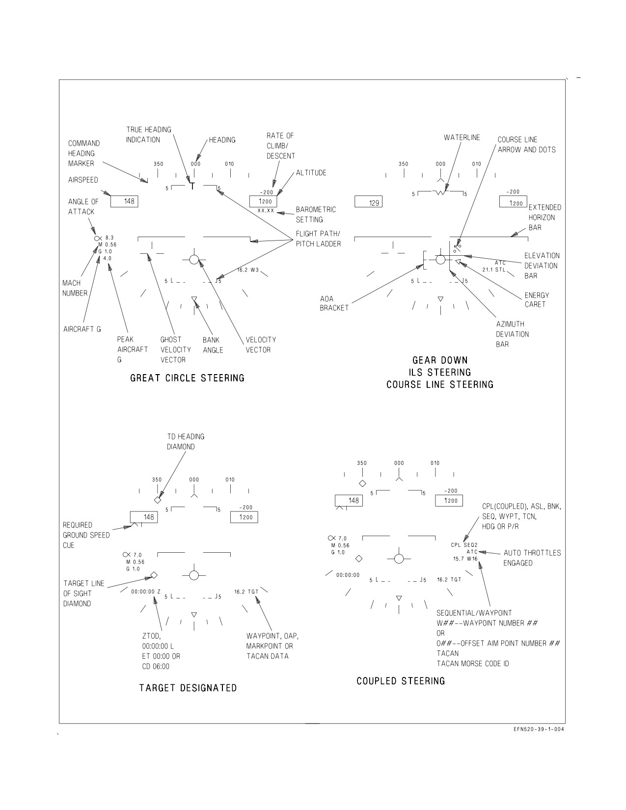
A1-F18EA-NFM-000
Figure 2-52. HUD Symbology (Sheet 1 of 2)
I-2-159
ORIGINAL
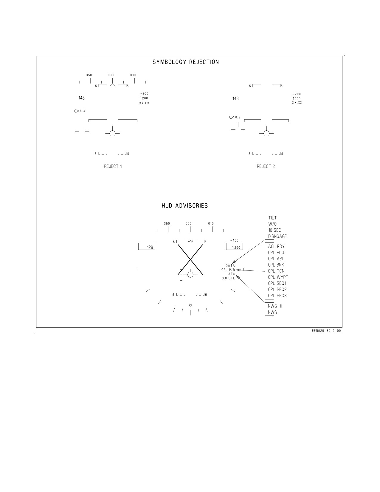
A1-F18EA-NFM-000
Figure 2-52. HUD Symbology (Sheet 2 of 2)
9. Bank angle scale. A bank angle scale and pointer are displayed at the bottom of the HUD for bank
angle reference up to 45°. At bank angles in excess of 47°, the bank angle scale pointer is limited at
45° and flashes.
10. Velocity vector. The velocity vector provides an outside world reference with regard to actual
aircraft flight path. The velocity vector represents the point towards which the aircraft is flying
(aircraft flight path). With a functioning INS, the velocity vector is driven by INS attitude and
velocities. If GPS data is valid, a ″hybrid″ GPS vertical velocity correction is used to correct errors
in the INS vertical velocity loop regardless of the INS mode switch position (CV, GND, NAV, or
IFA). If GPS data is not available for use in the hybrid correction, a VVEL advisory is displayed.
I-2-160
ORIGINAL
A1-F18EA-NFM-000
With a VVEL advisory displayed, sustained climbs and descents, such as
penetration from the marshal stack, can result in uncued (no cautions)
vertical velocity errors and a possible inaccurate velocity vector position.
Error magnitudes increase at slower airspeeds and lower altitudes. Errors
of up to 3° (actual flightpath 3° below the displayed velocity vector) have
been observed in the landing configuration. Three minutes of level flight
may be required to allow the INS to correct the vertical velocity errors.
NOTE
The VVEL advisory will be displayed if a GPS is not installed or if
masking prevents GPS positioning of a sufficient quality to ″aid″ the
INS vertical velocity loop.
The position of the velocity vector is limited to an 8° radius circle centered at the HUD optical
center. If the velocity vector reaches this limit during high angle of attack flight or large yaw and/or
drift angles, it flashes rapidly to indicate that it does not accurately indicate flight path (velocity vector
is HUD limited).
With GPS operating, if the INS velocity data becomes unreliable, the mission computer utilizes GPS
information. If INS velocity data becomes unreliable the mission computer utilizes FCC air data
function information and the last available wind data to compute the velocity vector and this degraded
velocity vector is indicated by a slow flashing of the symbol. In the NAV master mode, the velocity
vector may be caged to the vertical center line of the HUD by the cage/uncage switch on the throttle.
When it is caged, a ghost velocity vector is displayed at the true velocity vector position if that position
is more than 2° from the caged position. The flight path/pitch ladder and steering information are
referenced to the caged position. The ghost velocity vector flashes when limited. The flight path/pitch
ladder is referenced to the waterline symbol when the velocity vector is caged.
The velocity vector is automatically fixed at the horizon with WonW and ground speed less than 80
knots, and its status cannot be changed until WoffW. However, the velocity vector’s selected
caged/uncaged status does not change during touch-and-go landings if the ground speed remains above
80 knots.
11. Flight path/pitch ladder. The vertical flight path angle of the aircraft is indicated by the position
of the velocity vector on the flight path/pitch ladder. The horizon and flight path/pitch angle lines
represent the horizon and each 5° of angle between ±90°. Positive pitch lines are solid and are above
the horizon line. Negative pitch lines are dashed and are below the horizon line. The outer segments
of the lines point toward the horizon. Each line is numbered and the numbers rotate with the lines
so that inverted flight can easily be determined. To aid in determining flight path angle when it is
changing rapidly, the pitch lines are angled toward the horizon at an angle half that of the flight path
angle. For example, the 50° pitch line is angled 25° toward the horizon. In level flight, the pitch lines
are not angled. The zenith is indicated by a circle and the nadir is indicated by a circle with an X
in it. Aircraft pitch angle can be determined by comparing the tops of the altitude and airspeed
boxes (which represent the aircraft waterline) with the pitch ladder when the wings are level, but the
flight path/pitch ladder normally rotates about the velocity vector and determination of pitch angle
may be difficult at high roll angles.
I-2-161
ORIGINAL
A1-F18EA-NFM-000
12. Vertical velocity readout. This value is displayed above the altitude box and indicates vertical
velocity in feet per minute. This is displayed in the NAV master mode only. Descent is indicated by
a minus sign.
13. HUD landing symbology. When any two landing gear are down, the Mach number, g, and peak
g are deleted and an AOA bracket, extended horizon bar, waterline symbol, and energy caret appear.
The center of the AOA bracket represents the optimum approach AOA. The bracket moves lower
with respect to the velocity vector as AOA increases and moves higher as AOA decreases. When the
energy state of the aircraft is in equilibrium, the energy caret points to the ″right wing″ of the
velocity vector and the aircraft neither accelerates or decelerates. With an energy deficit, the energy
caret moves lower with respect to the velocity vector and the aircraft decelerates; with excess energy,
the energy caret moves higher and the aircraft accelerates.
14. Waypoint/OAP, mark point, TACAN, or target data. Waypoint/OAP and mark data consists of
range (horizontal), and the steer-to point identifier (W, O, or M) and number located on the lower
right corner of the HUD. TACAN data consists of slant range and a Morse code identifier located
on the lower right corner of the HUD. When a steer-to point is designated, range remains displayed
and the steer-to point identifier changes to TGT.
15. Coupled steering symbology. While coupled steering is engaged CPL SEQ#, CPL WYPT, CPL
TCN, CPL BNK, CPL ASL, CPL HDG, or CPL P/R appears on the right side of the HUD display
above the navigation data.
16. ILS symbology. When ILS steering is selected, an azimuth deviation bar (localizer) and elevation
deviation bar (glideslope) appear on the HUD.
17. ZTOD, LTOD, ET, and CD time. The ZTOD, LTOD, ET, or CD time is displayed on the lower
left corner of the HUD. These timers are mutually exclusive. Only one timer is available for display
on the HUD at a time. When the FIRAMS real time clock power up BIT passes, ZTOD does not need
to be entered, but when the FIRAMS real time clock power up BIT does not pass, ZTOD must be
entered. ET initializes to zero minutes and seconds. CD initializes to 6 minutes and zero seconds.
18. Command heading marker. When waypoint/OAP or TACAN direct great circle steering is
selected, the command heading marker is displayed just below the heading scale.
19. Steering arrow and dots. When waypoint/OAP or TACAN course line steering is selected, the
steering arrow and dots appear on the HUD.
20. Required ground speed cue. When steering is engaged to the target in a sequence, the required
ground speed cue appears under the airspeed box.
21. Target designation symbology. When a target is designated, a target designation symbol
(diamond) appears below the heading scale indicating target heading. Another target designation
symbol (diamond) appears indicating the target line of sight (LOS).
2.19.4.6.11 HUD Symbology Degrades. The avionics suite has built in redundancy with two mission
computers for data management and two DDIs (LOTs 21-24), or two MCs (LOTs 25 and up), for
symbol generation. Likewise, if the attitude select switch is in the AUTO or INS position, back up data
I-2-162
ORIGINAL
A1-F18EA-NFM-000
sources are automatically selected to provide HUD symbology when failures are detected. Refer to
figure 2-53, for the HUD displays discussed below.
a.
HUD Symbology Degrades with INS Failure. When a failure occurs in the INS, HUD
bank angle, velocity vector, pitch ladder, and heading indications can be expected to be
impacted. With GPS operating, the mission computer utilizes GPS information for the velocity
vector. If INS attitude is valid but INS velocities are not valid the mission computer
automatically uses the INS attitude and GPS velocities to position a non-flashing velocity
vector. With a degradation of the air data function (probe or pressure transmitter set damage
or failure) calibrated airspeed, barometric altitude, indicated Mach number, and vertical
velocity indications may be impacted.
When the INS experiences a total shutdown (dump) with the attitude select switch in AUTO
or INS, or if the attitude switch is deliberately placed in standby, a stationary waterline symbol
replaces the velocity vector indicating that the standby attitude reference indicator is now
providing attitude data. This failure is normally accompanied by the MASTER CAUTION
light, tone, and INS ATT caution. Place the attitude select switch in the STBY position,
crosscheck the HUD against standby instruments, and attempt an in-flight alignment.
Due to the tendency of the standby attitude reference indicator to precess, it is suggested that
flying in instrument meteorological conditions (IMC) using the ARI as a primary attitude
reference be minimized. A partial IFA (In-Flight Alignment) is always recommended whenever
possible to recover the INS attitude platform.
b.
HUD Symbology Degrades with Air Data Function Failure. An air data function
failure in the FCC results in loss of associated data from the HUD display as shown in figure
2-53. Such a failure also inhibits operation of cruise flight Automatic Throttle Control and
disables the altitude signal used for IFF altitude reporting. An air data function failure may
affect cabin air flow and cabin air temperature.
The pressure transmitter set can produce erroneous signals without cautions or advisories if
the pitot tube or AOA probes receive damage. As the air data function degrades, loss of some
or all of the following data from the HUD may occur:
(1) Calibrated airspeed or barometric altitude. The loss of calibrated airspeed and/or baro-
metric altitude data results in activation of the landing gear handle warning light and tone
with the gear UP. Aircrew action is to reference the applicable standby airspeed or altitude
indicator and then silence the tone.
(2) Angle of Attack. Loss of AOA in three or more FCC CHs causes AOA to be removed from
the HUD.
(3) Vertical velocity indicator. Pilot action on loss of the vertical velocity indication is to check
that the aircraft is in the NAV master mode and to reference the standby vertical velocity
indicator.
(4) Mach number. Pilot action on loss of the Mach number indication is to reference the
standby airspeed indicator.
If an AOA probe becomes jammed (does not move), the FCC continues to receive valid signals until
the pilot executes a maneuver that causes the reading between the AOA probes to differ more than 15°
I-2-163
ORIGINAL
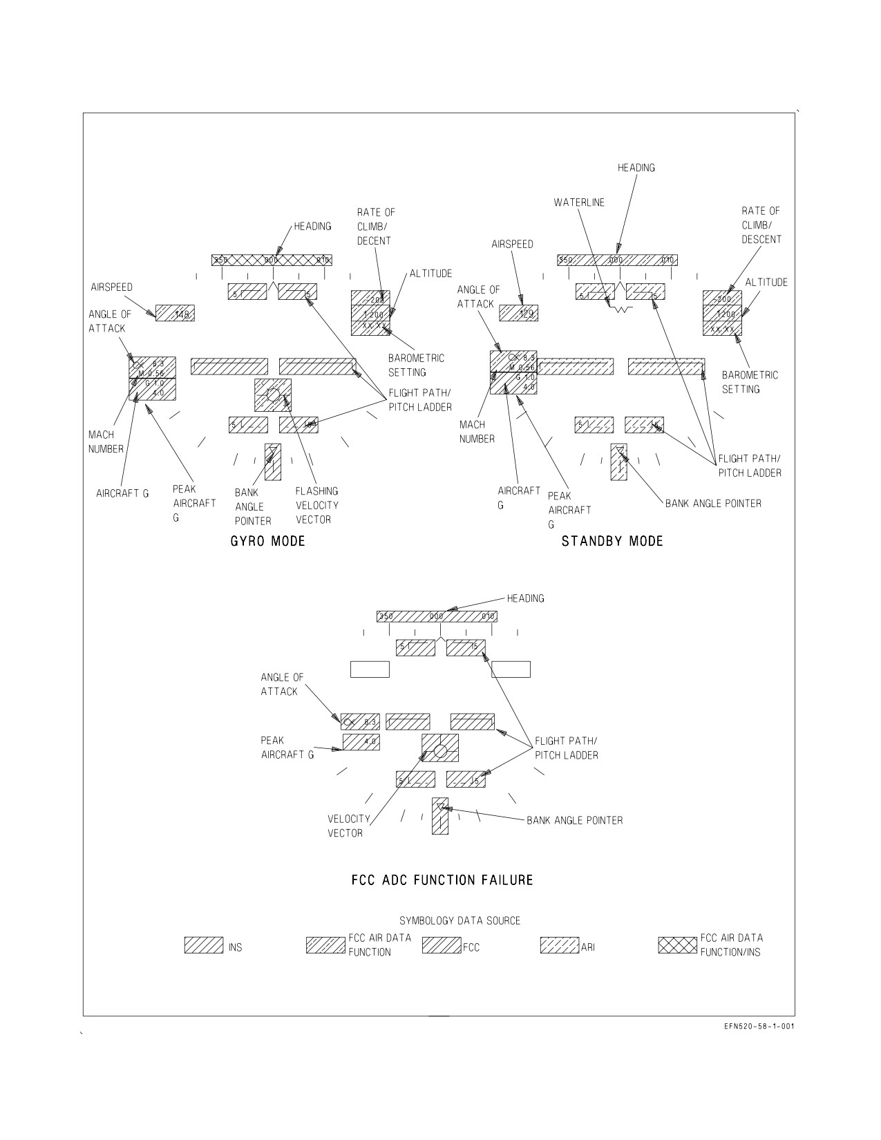
A1-F18EA-NFM-000
Figure 2-53. HUD Symbology Degrades
I-2-164
ORIGINAL
A1-F18EA-NFM-000
in UA or 5.5 to 15° in PA, depending on sideslip. HUD displayed airspeed may be inaccurate without
annunciation if a pitot tube is damaged.
A jammed, blocked, or damaged pitot tube/AOA probe may not be
annunciated if system errors are not large enough to set a caution. Be
alert for unannunciated pitot static and AOA errors during flight in icing
conditions or if damage is suspected after a bird strike or IFR basket
impact during inflight refueling.
Air data inputs from the MC are used by the INS to help smooth or dampen pitch ladder and
velocity vector position. A complete air data function failure does not immediately affect the pitch
ladder/velocity vector, but these displays eventually degrade. If subtle damage to the AOA probe is
suspected, the pilot should make a crosscheck of airspeed with a wingman if possible. The standby
airspeed indicator receives signals from the left pitot static probe, so it is accurate if only the right
probe is damaged. AOA checks with a wingman should be made in landing configuration if a jammed
AOA probe is suspected. Crosschecking in cruise configuration may give a satisfactory crosscheck, but
the probe may be bent in such a way that AOA anomalies are accentuated on landing configuration.
Landing with automatic throttle control (ATC) may be affected. If damage is suspected, ATC during
landing is not recommended.
When AOA is declared invalid (e.g., AOA Four Channel failure), the HUD AOA display and AOA
bracket are removed and the AOA indexer lights and approach lights are inoperative. GAIN ORIDE
provides fixed gains to the FCS and allows the pilot to select, through the FCS status display, either
the left or right probe. The center (INS) AOA value allows the pilot to compare AOA values to select
the undamaged probe. Once selected, this probe drives the HUD AOA display, AOA bracket, AOA
indexer, and approach lights. If the incorrect probe is selected, the information provided to the pilot
and LSO may be in error but has no impact on the flight control system as the gains are fixed. Notify
the LSO that a single probe has been selected.
2.19.4.6.12 HUD Advisory Data Symbology. The displays in figure 2-52 show some of the advisories
that can appear on the HUD in the NAV master mode. The advisories are associated with nose wheel
steering and approach power compensator. Although the advisories are shown on the gear down
display, most of them can appear on the basic HUD display. Refer to Part VII for description of data
link system and advisories.
The automatic throttle control/nosewheel steering advisories are displayed above the distance
display whenever the ATC or the NWS is engaged. If the ATC is disengaged by any means other than
actuation of the ATC engage/disengage switch, the advisory is flashed for 10 seconds before it is
removed from the display or, if a pilot attempt to engage ATC is not successful, ATC is flashed for 10
seconds and removed.
2.19.4.6.13 HUD BIT Checks. The HUD has two methods of built-in tests: manually initiated and
automatic test. Refer to BIT-Status Monitoring Subsystem for the procedures and displays used for
the HUD BIT checks.
2.19.4.7 CRS Set Switch. The course set switch manually sets the desired course on the HSI display.
2.19.4.8 HDG/TK Set Switch. The heading/ground track set switch manually sets the heading
marker on the desired heading/ground track on the HSI display.
I-2-165
ORIGINAL
A1-F18EA-NFM-000
2.19.5 Up Front Control Display (UFCD). The UFCD is on the main instrument panel below the
HUD in the front cockpit. In the rear cockpit, the UFCD is located below the MPCD in LOTs 21 thru
25, and above the MPCD or 8 x 10 display in LOT 26 AND UP. The UFCD is an active matrix liquid
crystal display with an IR touchscreen used for data entry inputs consisting of digits or NEWS, and
control of the CNI systems (autopilot modes, IFF, TACAN, ILS, data link, radar beacon, UHF/VHF
radios, and ADF), see figure 2-55. In addition, the touchscreen can be used as a multi-function display
for display formats, including video. The UFCD is used in conjunction with the two DDIs, the 8 x 10
display and the MPCD to enter navigation, sensor, and weapon delivery data. UFCD option selections
and inputs are transmitted directly to the MPCD and on to the mission computers. (The mission
computers pass these inputs to the control converter (CC) for CNI equipment control). The UFCD is
NVG compatible. In the F/A-18F, the front and rear cockpit UFCDs operate independently. When
different formats are being displayed, the only data common to both UFCDs is radio channel and
frequency information. Both cockpit UFCDs present the results of changes to radio channels or
frequencies at the same time, regardless of which cockpit performed the change. The cockpit not
performing data entry does not see touch highlights as the data is entered, only the result of the data
entry. If both pilot and WSO enter digits on the keypad for the same option, both entries are accepted,
with the second entry overwriting the first. When pilot and WSO are on the same data entry or CNI
format, asterisks are provided in the top left and right of the scratch pad.
(LOT 26 AND UP) The aft UFCD is electrically controlled through the 8 x 10 display Off/On/
Brightness knob when it is installed. The aft UFCD flashes STANDBY when the MC1 communication
to the UFCD is disrupted. A standby display pattern in the the center of the UFCD display surface,
similar to the DDI pattern, indicates degraded image processing from MC1. When the Mono video
connection from the 8 x 10 display is lost or degraded, the aft UFCD will not display anything. When
video synchronization is lost or degraded, the aft UFCD may display symbology that is not coordinated
with the video. If the interface between MC1 and the aft UFCD is lost, the touch screen capability and
brightness/contrast control will not work. When MC1 is inoperative, the aft UFCD is not capable of
displaying format symbology or analog video.
When the pilot or WSO touch a keypad option on the touch screen a highlight appears indicating
that the option has been selected. Figure 2-55 shows an example of a selected option. When a new
format is selected on the touchpad, the highlight does not remain on the new format.
Keypad options use a first finger in mechanization. Only one option can be selected at a time. If two
or more selections are attempted at one time, none of them are considered valid.
Some formats initialize with data in the scratchpad, e.g., the COMM sublevel of the CNI format
initializes with the comm frequency in the scratchpad. When data entry is started, the digits in the
scratchpad are blanked, allowing data entry. If a comm frequency is being entered the decimal remains
displayed, allowing frequency entry in relation to the decimal point to be viewed.
The UFCD uses a double clear mechanism. The first selection of the CLR keypad option removes the
last digit that was entered in the scratchpad. The second selection of the CLR option removes all the
digits which have been entered in the scratchpad. If the scratchpad is flashing due to the 10 second
timer (no entries in the previous 10 seconds), pressing CLR stops the flashing and performs the
previously described CLR function. If the scratchpad is flashing due to an error, pressing CLR stops
the flashing and removes all digits from the scratchpad.
I-2-166
ORIGINAL