F18. FLIGHT MANUAL (2008) - page 17

A1-F18EA-NFM-000
NATOPS CHANGE RECOMMENDATION
OPNAV/FORM 3710/6(4-90) S/N 0107-LF-009-7900
DATE
TO BE FILLED IN BY ORIGINATOR AND FORWARDED TO MODEL MANAGER
FROM (originator)
Unit
TO (Model Manager)
Unit
Complete Name of Manual/Checklist
Revision Date
Change Date
Section/Chapter
Page
Paragraph
Recommendation (be specific)
r CHECK IF CONTINUED ON BACK
Justification
Signature
Rank
Title
Address of Unit of Command
TO BE FILLED IN BY MODEL MANAGER (Return to Originator)
FROM
Date
TO
Reference
(a) Your change Recommendation Dated
r Your change recommendation dated
is acknowledged. It will be held for action of the
review conference planned for
to be held at
r Your change recommendation is reclassified URGENT and forwarded for approval to
by my DTG
/S/
AIRCRAFT
MODEL MANAGER
53
ORIGINAL
A1-F18EA-NFM-000
YOUR RESPONSIBILITY
NATOPS Flight Manuals are kept current through an active manual change program. Any
corrections, additions, or constructive suggestions for improvement of content of the manual should be
submitted by routine or urgent change recommendation, as appropriate, at once.
NATOPS FLIGHT MANUAL INTERIM CHANGES
Interim changes are changes or corrections to NATOPS manuals promulgated by CNO or
COMNAVAIRSYSCOM. Interim changes are issued either as printed pages, or as a Naval message.
The Interim Change Summary page is provided as a record of all interim changes. Upon receipt of a
change or revision, the custodian of the manual should check the updated Interim Change Summary
to ascertain that all outstanding interim changes have been either incorporated or canceled; those not
incorporated shall be recorded as outstanding in the section provided.
CHANGE SYMBOLS
Revised text is indicated by a black vertical line in either margin of the page, adjacent to the affected
text, like the one printed next to this paragraph. The change symbol identifies the addition of either
new information, a changed procedure, the correction of an error, or a rephrasing of the previous
material.
WARNING, CAUTIONS, AND NOTES
The following definitions apply to ‘‘WARNINGS’’, ‘‘CAUTIONS’’, and ‘‘NOTES’’ found throughout
the manual.
An operating procedure, practice, or condition, etc., which may result in
injury or death if not carefully observed or followed.
An operating procedure, practice, or condition, etc., which may result in
damage to equipment if not carefully observed or followed.
NOTE
An operating procedure, practice, or condition, etc., which is essential
to emphasize.
WORDING
The concept of word usage and intended meaning which has been adhered to in preparing this
54
ORIGINAL
A1-F18EA-NFM-000
manual is as follows:
″Land as soon as possible″ means to land at the first site which a safe landing can be made.
″Land as soon as practical″ means extended flight is not recommended. The landing site and
duration of flight is at the discretion of the pilot in command.
‘‘Shall’’ has been used only when application of a procedure is mandatory.
‘‘Should’’ has been used only when application of a procedure is recommended.
‘‘May’’ and ‘‘need not’’ have been used only when application of a procedure is optional.
‘‘Will’’ has been used only to indicate futurity, never to indicate any degree of requirement for
application of a procedure.
AIRSPEED
All airspeeds in this manual are in knots calibrated airspeed (KCAS) unless stated in other terms.
TERMINOLOGY
To standardize terminology throughout this publication, the following guidelines should be followed:
a. When specifying a switch, handle, or knob to be actuated in an emergency procedure, the name
of the switch, handle or knob should be written as it is labeled in the cockpit (i.e. LDG GEAR
handle).
b. When referencing a position of a switch, handle, or knob, the label as shown in the cockpit
should be used (i.e. ECS MODE switch − OFF/RAM).
c. LOT numbers should be used vice BUNO numbers when the entire LOT is affected. For
multiple LOTs use LOTs XX−XX or LOT XX and up as appropriate.
d. For MC OFP’s use terminology such as ″Prior to MC OFP 18E″ or ″MC OFP 18E and up″ to
avoid requiring a NATOPS change with each subsequent OFP release.
e. Procedures which are nested in other procedures such as the Emergency Oxygen Procedure
should contain only immediate action items.
f. When emergency procedures are referenced in the PCL, page numbers should be included to
facilitate quick location of the referenced procedure.
MANUAL DEVELOPMENT
This NATOPS Flight Manual was prepared using a concept that provides the aircrew with
information for operation of the aircraft, but detailed operation and interaction is not provided. This
concept was selected for a number of reasons: reader interest increases as the size of a technical
publication decreases, comprehension increases as the technical complexity decreases, and accidents
decrease as reader interest and comprehension increase. To implement this streamlined concept,
observance of the following rules was attempted:
a. Aircrew shall be considered to have above-average intelligence and normal (average) common
sense.
55
ORIGINAL
A1-F18EA-NFM-000
b. No values (pressure, temperature, quantity, etc.) which cannot be read in the cockpit are
stated, except where such use provides the pilot with a value judgement. Only the information
required to fly the airplane is provided.
c. Notes, Cautions, and Warnings are held to an absolute minimum, since almost everything in
the manual could be considered a subject for a Note, Caution, or Warning.
d. No procedural data are contained in the Descriptive Section, and no abnormal procedures
(Hot Starts, etc.) are contained in the Normal Procedures Section.
e. Notes, Cautions and Warnings are not used to emphasize new data.
f. Multiple failures (emergencies) are not covered.
g. Simple words in preference to more complex or quasi-technical words are used and
unnecessary and/or confusing word modifiers are avoided.
A careful study of the NATOPS Flight Manual will probably disclose a violation of each rule stated.
In some cases this is the result of a conscious decision to make an exception to the rule. In many cases,
it only demonstrates the constant attention and skill level that must be maintained to prevent slipping
back into the old way of doing things.
In other words, the ‘‘Streamlined’’ look is not an accident, it takes constant attention for the
NATOPS Flight Manual to keep the lean and simple concept and to provide the aircrew with the
information required.
56
ORIGINAL
A1-F18EA-NFM-000
58
(Obverse Blank)
ORIGINAL
A1-F18EA-NFM-000
PART I
THE AIRCRAFT
Chapter
1 - Aircraft
Chapter
2 - Systems
Chapter
3 - Servicing and Handling
Chapter
4 - Operating Limitations
59
(Reverse Blank)
ORIGINAL
A1-F18EA-NFM-000
CHAPTER 1
The Aircraft
1.1 AIRCRAFT DESCRIPTION
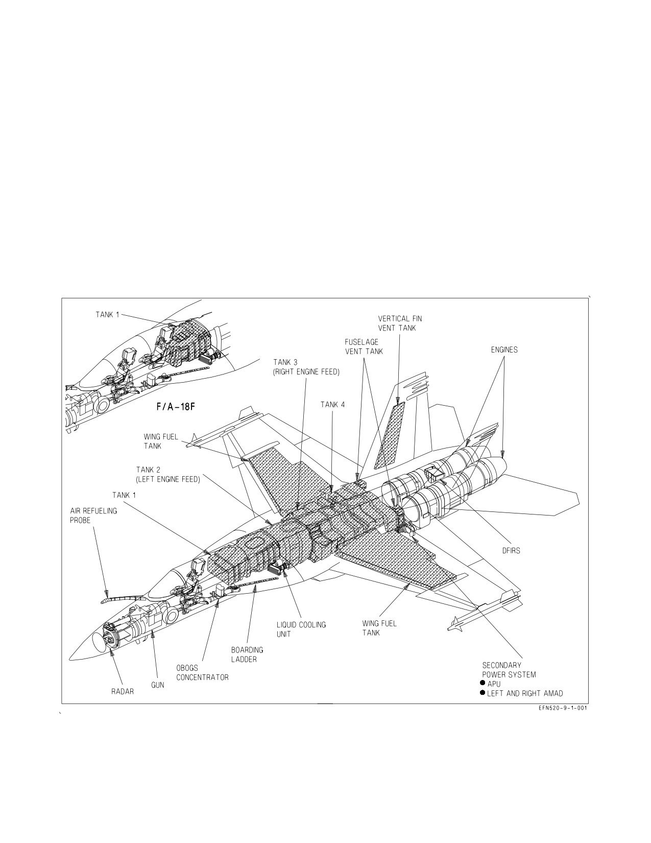
1.1.1 Meet The Super Hornet. The F/A-18E/F Super Hornet is a carrier based strike fighter aircraft
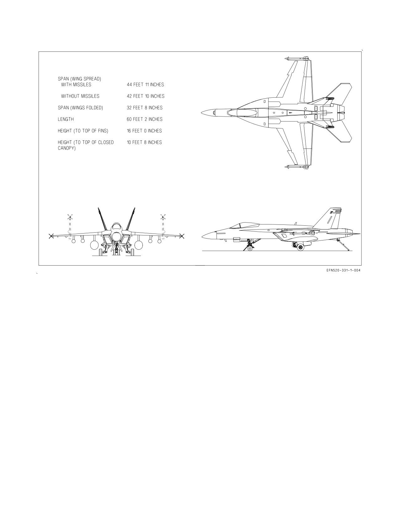
built by McDonnell Douglas Corporation. The general arrangement, approximate dimensions, and
cockpit layout are shown in Figure 1-1, Figure 1-2, and the Cockpit Foldout section, respectively. The
multi-mission aircraft has an internal 20 mm gun and can carry AIM-7, AIM-9, and AIM-120 air-to-air
missiles; and numerous air-to-ground weapons. The aircraft fuel load may be increased with the
addition of up to five external fuel tanks. The aircraft can be configured as an airborne tanker by
carrying a centerline mounted air refueling store.
Figure 1-1. General Arrangement
The aircraft is powered by two General Electric F414-GE-400 turbofan engines utilizing Full
Authority Digital Engine Control (FADEC). The aircraft features a variable camber mid-wing with
I-1-1
ORIGINAL
A1-F18EA-NFM-000
Figure 1-2. Approximate Dimensions
leading edge extensions (LEX) mounted on each side of the fuselage. Twin vertical tails are angled
outboard 20 degrees from the vertical.
The aircraft is designed with relaxed static stability to increase maneuverability and to reduce
approach and landing speed. The aircraft is controlled by a digital fly-by-wire Flight Control System
through hydraulically actuated flight control surfaces: ailerons, twin rudders, leading edge flaps,
trailing edge flaps, LEX spoilers, and differential stabilators. The leading edge of the wing incorporates
a ‘‘snag,’’ which increases outboard wing area and increases roll authority in the approach and landing
configuration. A speed brake function is provided by differential deflection of the primary flight
control surfaces.
The pressurized cockpit is enclosed by an electrically operated clamshell canopy. An aircraft
mounted auxiliary power unit (APU) provides self-contained start capability for the engines.
1.1.2 Aircraft Gross Weight. Basic weight is approximately 31,500 pounds for the F/A-18E and
32,000 pounds for the F/A-18F. Refer to applicable DD 365-3 for accurate aircraft weight.
1.1.3 F/A-18F. The F/A-18F is the two seat model of the Super Hornet and is configured with
tandem cockpits. The rear cockpit can be configured with a stick, throttles, and rudder pedals (trainer
configuration); or with two hand controllers, a UFCD adapter, and foot-operated communication
switches (missionized configuration). The rear cockpit controls and displays operate independently of
those in the front cockpit.
I-1-2
ORIGINAL
A1-F18EA-NFM-000
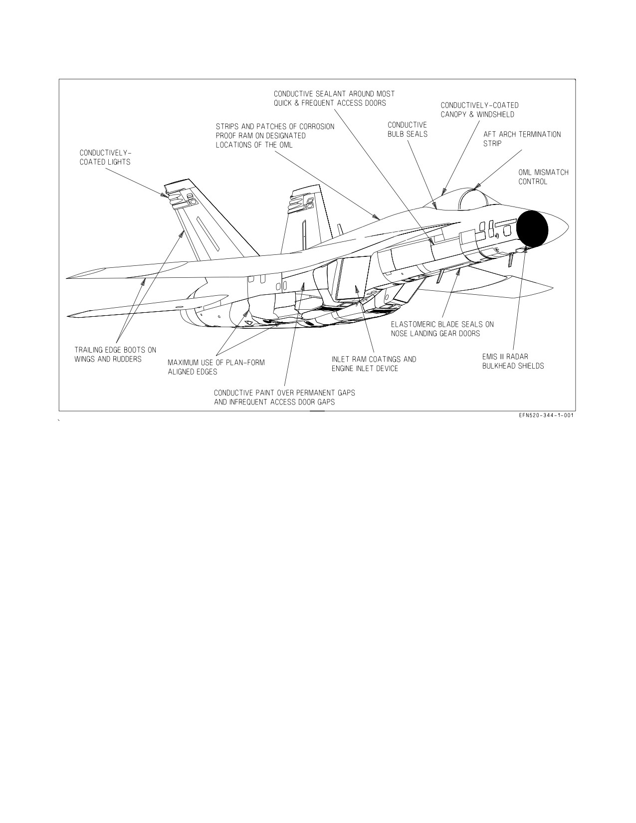
Figure 1-3. Radar Cross Section (RCS) Reduction
1.1.4 Radar Cross Section (RCS) Reduction. RCS reduction is a significant feature of the F/A-
18E/F. While the maintenance community is tasked with maintaining the RCS features of the aircraft,
it is in the best interests of the aircrew community to take an active role to ensure the survivability
characteristics of the aircraft are retained.
RCS reduction is accomplished through numerous airframe design features. See figure 1-3. The
baseline feature is planform alignment of as many surface edges as feasible. The outer moldline of the
aircraft is treated to make it a smooth, conductive surface in order to reduce radar scattering.
Treatment entails metalizing the navigation lights, canopy, and windshield. Permanent joints and
gaps around infrequently opened panels are filled with a form-in-place (FIP) sealant, which is blended
flush and conductively painted. Gaps around frequently opened panels are filled with a conductive FIP
(CFIP) sealant, which allows for easier repair. Conductive tape is applied to a few gaps where there is
no substructure to support FIP material, such as along LEX edges. Conductive tape can also be used
to quickly repair damaged FIP joints.
Since CFIP in the gaps around frequently opened panels will experience the most wear and tear, a
corrosion-proof radar absorbing material (RAM) is applied in front of many of these gaps. RAM is also
applied (1) on the inlet lip and duct, (2) as diamond-shaped patches around drain holes, and (3) in
various locations that tend to highly scatter radar energy such as around pitot tubes, vertical tail
openings, vents and screens, flap hinges and fairings, and portions of the pylons and external tanks. A
multi-layer RAM is used in a few locations, such as around AOA probes and on the top, front surface
of the pylons.
I-1-3
ORIGINAL
A1-F18EA-NFM-000
Gaps around landing gear doors are treated in two ways. Nose landing gear doors use flexible
conductive blade seals on leading and trailing edges; main landing gear door edges are wrapped with
RAM. Scattering from trailing edges (i.e., trailing edge flaps and rudders) is controlled by a radar
absorbing boot which is bonded to the surface. Scattering from the back edge of the windshield is
controlled by a gray, laminated material called the aft arch termination strip.
The engine inlet ducts incorporate a device to minimize engine front face scattering. The edge of the
canopy incorporates a conductive bulb seal to block radar reflections from that joint. Conductive bulb
seals are also used where there is significant structural flexure, such as at the wing-to-LEX interface.
Eleven electro magnetic interference shields (EMIS) III radar shields are permanently installed on
the radar antenna hardware. To allow the aircraft to achieve its full RCS reduction potential, a
missionized kit consisting of twelve more EMIS III radar bulkhead shields, are installed for combat
missions only. Additionally, SUU-79 pylons can be fitted with a set of low observable (LO) hardware.
1.2 BLOCK NUMBERS
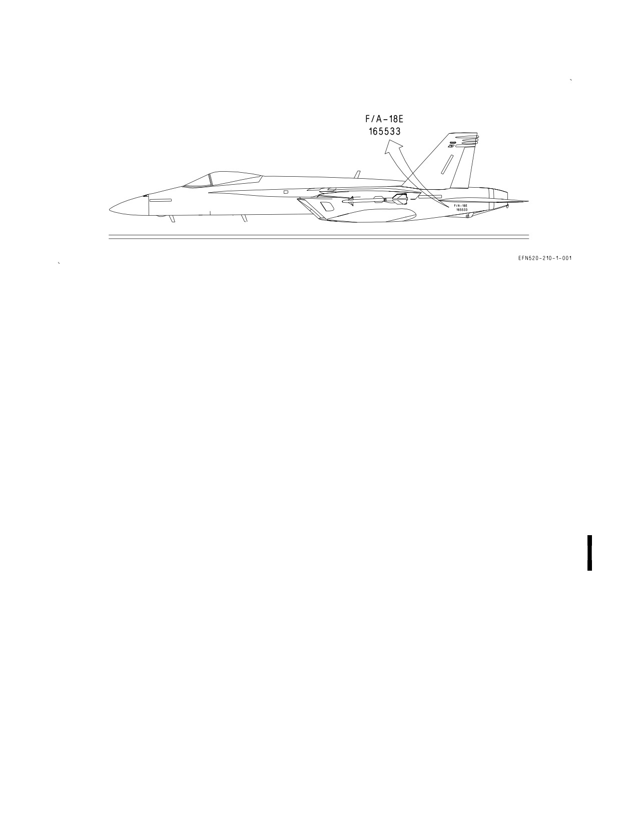
See figure 1-4 for block numbers and bureau numbers for each lot of aircraft. The baseline for this
NATOPS manual is aircraft 165779 (Lot 23) and up. Differences from the baseline aircraft for aircraft
165533 thru 165679 (Lot 21 and Lot 22) are presented in Appendix B of this manual.
I-1-4
ORIGINAL
A1-F18EA-NFM-000
LOT
F/A-18E
F/A-18F
LOT 21
165533 - 165540
165541 - 165544
LOT 22
165660 - 165667
165668 - 165679
LOT 23
165779 - 165792
165793 - 165808
LOT 24
165860 - 165874
165875 - 165895
LOT 25
165896 - 165909
165910 - 165934
LOT 26
166420 - 166448
166449 - 166467
LOT 27
166598 - 166609
166610 - 166642
LOT 28
166643 - 166657
166658 - 166684
LOT 29
166775 - 166789
166790 - 166816
LOT 30
166817 - 166841
166842 - 166854
Figure 1-4. LOT NUMBER/BUNO
I-1-5
(Reverse Blank)
ORIGINAL
A1-F18EA-NFM-000
CHAPTER 2
Systems
2.1 POWER PLANT SYSTEMS
2.1.1 Engines. The aircraft is powered by two General Electric F414-GE-400 engines. The engines
are low bypass, axial-flow, twin-spool turbofans with afterburner. The three stage fan (low pressure
compressor) and the seven stage high pressure compressor are each driven by a single stage turbine.
The basic functions are supported by the engine driven accessory gearbox which drives the engine fuel
pump, variable exhaust nozzle (VEN/start) fuel pump, lubrication and oil scavenge pump, engine fuel
control, and alternator. Fuel flow from the VEN/start pump is used to drive the VEN actuator and to
provide initial fuel pressure for main engine start.
The uninstalled military thrust (MIL) of each F414-GE-400 engine is approximately 13,900 pounds
with maximum afterburner thrust (MAX) in the 20,700 pound class.
An inlet device is installed in each engine intake to reduce the aircraft radar signature and to
improve survivability.
2.1.1.1
FADEC - Full Authority Digital Engine Control. Engine operation is controlled by a full
authority digital engine control (FADEC), mounted on the engine casing. Each FADEC computer has
two central processor units, channel A (CH A) and channel B (CH B), and is integrated with the
Mission Computers (MCs), flight control computers (FCCs), and throttles. Normally, both FADEC
channels monitor engine and control system operation with one channel in control and the other in
standby. The channel currently in control is boxed on the SUPT MENU/ENG display.
In the event of a control system failure, the FADEC automatically selects the channel with better
capability. Manual FADEC channel transfer can be commanded by selecting the CH A or CH B
pushbutton on the ENG display. When the throttle is at or above IDLE, the FADEC transfers control
to the other channel only if the requested channel’s health is no worse than the channel in control.
FADEC software implements the engine control schedules by modulating fuel flow and engine
geometry for the current flight conditions and the ″requested″ throttle setting. With the throttles
matched, engine parameters may vary significantly between the engines as control schedules are
adjusted for optimum performance. Therefore, a mismatch between engine parameters is not a sign of
degraded performance as long as ENG STATUS is NORM. FADEC cooling is provided by the fuel
system.
2.1.1.1.1
FADEC Power Sources. Prior to first engine start, the battery is used to power CH A of
both FADECs. When N2 reaches 10% rpm during start, the engine driven alternator comes online and
powers both channels of its corresponding FADEC. When an aircraft generator comes online (N2
greater than 60%), the aircraft’s electrical system provides power to both channels of the other FADEC
as well. With both engines operating, each engine driven alternator is the primary source of FADEC
power with the aircraft’s 28 vdc essential bus as backup. When both channels of a FADEC are powered
after initial start, the FADEC automatically switches operation to the channel which was not in control
during the last flight/engine run.
I-2-1
ORIGINAL
A1-F18EA-NFM-000
Ten seconds after reaching idle power, the FADEC attempts to switch to the 28 vdc essential bus to
verify that backup power is available. If backup power is inadequate/inoperative, the FADEC declares
a channel degrade (dual channel lineout) and sets a 6A8 or 6C8 MSP code (L or R FADEC/aircraft 28V
fail). These degrade indications appear if the first engine is started with the corresponding GEN switch
OFF, and requires a FADEC reset to restore normal engine indications.
2.1.1.1.2
Engine Status. Engine status is reported by the FADEC and appears on the ENG
STATUS line of the ENG display. The levels of engine performance capability, listed in descending
order, are:
NORM
Engine performance is normal
PERF90
10% or less thrust loss and/or slower engine transients. Afterburner is not
inhibited
AB FAIL
No afterburner capability
THRUST
Engine thrust is limited to between 40% and 90% and significantly slower
transients
IDLE
Engine is limited to idle power only
SHUTDOWN Engine automatically shut down
2.1.1.1.3
FADEC/Engine Degrades. FADEC/engine degrades fall into two categories: minor failures
which do not affect engine operability and significant failures that do affect engine operability.
Due to a high level of FADEC redundancy, most minor control system failures do not cause any
degradation in engine performance (ENG STATUS remains NORM). Cockpit indications for these
types of failures are slightly different depending on whether the aircraft is inflight or on the ground.
Inflight -
a. FADEC and BIT advisories.
b. ENG STATUS - NORM.
c. OP GO indication for the affected engine channel on the BIT/HYDRO MECH display.
On the ground or below 80 KCAS after landing -
a. FADEC and BIT advisories.
b. ENG STATUS - NORM.
c. DEGD replaces OP GO for the affected engine channel on the BIT/HYDRO MECH display.
d. Both CH A and CH B lined out on the ENG display.
A FADEC OP GO or DEGD with an ENG STATUS of NORM is an indication of a loss of control
system redundancy and not of a loss of engine operability. Therefore, a FADEC OP GO inflight should
be considered informative and should not mandate a mission abort. However, on the ground, the
I-2-2
ORIGINAL
A1-F18EA-NFM-000
FADEC DEGD and dual channel lineout indications are intended to prevent takeoff with a known loss
of redundancy and maintenance action is required. Therefore, takeoff with a FADEC DEGD indication
(dual channel line out) is prohibited.
Significant failures which do cause degradation in engine performance have the following indications
both inflight and on the ground:
a. L or R ENG caution and voice alert.
b. FADEC and BIT advisories.
c. ENG STATUS change on the ENG display.
d. DEGD indication for the affected engine channel on the BIT/HYDRO MECH display.
e. Both CH A and CH B lined out on the ENG display.
2.1.1.1.4
FADEC Reset. When a throttle is OFF, the corresponding FADEC uses a channel change
request as a FADEC software reset. FADEC reset capability is provided to clear a DEGD indication
which was caused by a momentary FADEC fault (e.g., startup power transient). A FADEC reset should
only be performed for DEGD indications which occur on the ground and which do not result in a
change of ENG STATUS. For a FADEC OP GO inflight, engine shutdown and FADEC reset is not
recommended as the engine is functioning normally. In all other circumstances, a FADEC reset should
not be attempted, particularly airborne, as any degrade in ENG STATUS is most likely indicative of
the failure of a mechanical component. Under these conditions, the engine may fail to restart following
a shutdown and FADEC reset attempt.
2.1.1.1.5
Ignition System. The FADEC provides simultaneous control of the main and afterburner
igniters via the engine driven alternator and ignition exciter. Ignition
(both main engine and
afterburner) is commanded whenever:
a. N2 rpm is between 10% and 45% during engine start.
b. Flameout occurs.
c. Throttle is advanced into afterburner, remaining on until afterburner light off is sensed.
d. The gun is fired, or any wing pylon mounted A/A or forward firing A/G weapon is launched.
Ignition remains on for 5 seconds.
2.1.1.1.6
Oil Pressure Sensing System. The oil pressure sensing system utilizes an oil pressure
transducer and a separate oil pressure switch. The transducer provides an oil pressure value for display
in the cockpit. The oil pressure switch provides an additional source to confirm the presence of oil
pressure if the oil pressure transducer fails.
If a L or R OIL PR caution is set with a valid cockpit readout, actual engine oil pressure is below
scheduled limits. If the cockpit readout is zero with no caution set, the oil pressure transducer has
failed and the pressure switch is inhibiting the caution.
2.1.1.1.7
Engine Idle Schedules. Each FADEC modifies engine idle schedules based on weight on
wheels (WonW) status, aircraft flight condition, engine bleed demand, and environmental control
system (ECS) mode of operation. The purpose of idle scheduling is to ensure that engine bleed output
I-2-3
ORIGINAL
A1-F18EA-NFM-000
is always sufficient to run the ECS, particularly the aircrew onboard oxygen generating system
(OBOGS).
Baseline idle schedules are used during normal engine operation and moderate environmental
conditions, and are set as a function of pressure altitude and WonW status. With WonW and airspeed
below 80 knots, the FADEC commands ground idle by reducing the engine compressor discharge
pressure (CDP) (typically a slight decrease in N2 rpm) from the inflight idle setting. The throttle
handle angle (THA) for ground and inflight idle are identical.
In LOT 26 and up, with WoffW, spin recovery mode not engaged, and inflight refueling probe and
landing gear (and hook in LOT 24 and below) retracted, baseline flight idle thrust LOT 26 and up is
higher than in LOT 25 and below. Ground idle thrust is not affected.
Alternate idle schedules are used when engine bleed demands are high
(e.g., hot ambient
temperatures, high ECS output, RECCE configuration, engine or windshield anti-ice operation, or
ECS OFF/RAM mode). When an alternate idle schedule is requested, the FADEC increases the
minimum CDP that is commanded at idle power (typically a slight increase in N2 rpm), which may also
result in a noticeable decrease in throttle response at the lower end of the throttle range. With the
throttles near flight idle, a small engine transient may be noticed when an alternate idle schedule is
activated or when a transition between alternate idle schedules occurs.
In LOT 26 and up, when an alternate idle schedule is activated flight idle thrust can be double that
for LOT 25 and below aircraft.
Alternate idle schedules are deactivated with WonW, when spin recovery mode is engaged, or when
the inflight refueling probe or landing gear (or hook in LOT 24 and below) are extended. When
alternate idle schedules are deactivated in LOT 26 and up, a small noticeable engine transient may
occur with the throttle near flight idle, and the resulting flight idle thrust is identical to LOT 25 and
below baseline flight idle thrust.
2.1.1.1.8
Fan Speed Lockup. The fan speed lockup system prevents inlet instability (buzz) at high
Mach by holding engine speed and airflow at military power levels when the throttle(s) are retarded
below MIL. Speed lockup is activated when the aircraft accelerates above Mach 1.23 and deactivated
when the aircraft decelerates below Mach 1.18.
2.1.1.1.9
SETLIM - Supersonic Engine Thrust Limiting. SETLIM minimizes the potential for an
aircraft departure due to asymmetric thrust following an engine stall or flameout at certain supersonic
(Mach greater than 1.8) or high-q conditions equivalent to approximately 700 KCAS at sea level or 750
KCAS at 25,000 feet. If the FADEC detects a stall or flameout condition, this function terminates
afterburner operation in both engines. Normal afterburner operation is restored 12 seconds after
engine recovery or immediately when airspeed drops below Mach 1.7 and q-conditions are equivalent
to approximately 650 KCAS at sea level or 710 KCAS at 25,000 feet.
2.1.1.1.10 RATS - Reduced Authority Thrust System. The reduced authority thrust system (RATS)
reduces the wind-over-deck required for carrier landings by rapidly reducing thrust at the beginning
of a successful arrestment, reducing the energy absorbed by the arresting gear. RATS logic, only
resident in MC1, declares a successful arrestment if the landing gear and arresting hook are down and
longitudinal deceleration is more than 1.0g (a typical arrestment is approximately 3g). MC1 sends a
″set RATS on″ signal to the FADECs, which reduce thrust to approximately 70% of MIL power. RATS
logic also senses WonW, wheel speed (less than 20 knots), and THA to prevent the engines from
spooling back to MIL power at the end of cable pullout. RATS operation is canceled when the throttles
are reduced to IDLE (THA less than 10°). RATS operation is inhibited during single engine operation.
I-2-4
ORIGINAL
A1-F18EA-NFM-000
RATS operation can be overridden by advancing the throttles to full afterburner (THA within 2° of
the MAX stop). With RATS enabled, afterburner operation is inhibited if the throttles are
subsequently advanced to afterburner (below the MAX stop). If the throttles are in afterburner (below
the MAX stop) during an arrested landing, RATS functions normally, rolling back both the main
engine and the afterburner.
2.1.1.1.11 AGI (Armament Gas Ingestion) Protection. AGI protection provides preemptive engine
ignition in case armament gas ingestion causes an engine flameout. As mechanized, AGI protection is
a backup to the FADEC’s inherent flameout detection and relight logic. While flight test data indicates
that the system may not be needed, AGI protection remains functional.
The AGI signal is sent by the Stores Management Set (SMS) to the FADECs and is used to initiate
engine ignition (both engines) for 5 seconds. The signal is sent when the gun is fired, or or any wing
pylon mounted A/A or forward firing A/G weapon is launched. AGI is functional in the SIM mode as
well as the tactical mode.
2.1.1.1.12 IBU (Increased Bleed Usage) Signal In LOT 26 and up, during high bleed flow rates, the
mission computers may send the FADECs an IBU signal to prevent engine turbine overheating. When
IBU scheduling is active, hot day MIL and MAX thrust may be reduced by up to 1.5% compared to
LOT 25 and below aircraft.
2.1.1.1.13 ABLIM - Afterburner Limiting Function. The ABLIM function limits engine power to
half afterburner with the throttles at MAX to prevent engine stalls due to exhaust gas ingestion. The
system is only to be used during carrier-based operations. The function is pilot selectable with WonW.
The system defaults to disabled (unboxed) after engine start. The ABLIM function is activated by
selecting (boxing) the ABLIM option on the CHKLIST format with the FLAP switch in HALF or
FULL. The ABLIM advisory is set to confirm that the function has been activated on both engines.
With the function activated, only half afterburner power is available with the throttles at MAX.
Indicated fuel flows are reduced from 35,000 to 45,000 pph to about 25,000 pph. The function is
automatically deactivated with acceleration due to a catapult launch, at 80 KCAS, or with WoffW. The
ABLIM function is disabled with a FCC CH 1, FCC CH 2, FCC CH 4, MC1, or FADEC failure.
2.1.1.2
Engine Related Cautions and Advisories. The following engine related cautions and adviso-
ries are described in the Warning/Caution/Advisory Displays in Part V:
D L or R EGT HIGH
D L or R OIL HOT (engine or AMAD)
D L or R ENG
D L or R OIL PR
D L or R ENG VIB
D L or R OVRSPD
D FADEC HOT (ground only)
D L or R STALL
D L or R FLAMEOUT
D ABLIM advisory
D NO RATS
D FADEC advisory
2.1.1.3
Engine Anti Ice. Each engine supplies its own bleed air for engine and inlet device anti-ice.
The engine anti-ice system is normally controlled by the ENG ANTI ICE switch. However, after engine
start (initial FADEC power-up or following a FADEC reset), the engine anti-ice system automatically
turns on 45 seconds after the engine reaches idle power and remains on for 30 seconds, provided the
throttle remains at IDLE. The appropriate LHEAT or RHEAT advisory is displayed during this
anti-ice functional test.
With the ENG ANTI ICE switch ON, anti-ice air flows as long as INLET TEMP is between -40
and +15°C. Outside of these limits, anti-ice airflow is terminated immediately if airborne, or after 60
seconds with WonW. When anti-ice air is flowing, N2 rpm increases approximately 2%, and EGT
increases approximately 5°C.
I-2-5
ORIGINAL
A1-F18EA-NFM-000
The inlet device has an anti-ice leak detection system. The system detects hot air leaks from the
device air manifold or in the cavity between the device and the airframe and sets the L or R DEVC
BLD caution. A hot air leak into the cavity reduces device anti-ice capability and may structurally
damage the device and surrounding structure.
2.1.1.3.1
ENG ANTI ICE Switch. The ENG ANTI ICE switch is located on the ECS panel on the right
console.
ON Activates the engine anti-ice system
OFF Deactivates the engine anti-ice system
TEST Checks ice detector operation and displays the INLET ICE caution (indicating proper
operation).
2.1.1.3.2
Engine Anti-Ice Advisories. The L HEAT and R HEAT advisories are displayed when the
engine anti-ice system is activated (ENG ANTI ICE switch ON or anti-ice functional test) and no
system failures are detected. If an engine anti-ice failure occurs with the system turned on, the HEAT
FAIL caution is displayed and the corresponding L HEAT or R HEAT advisory is removed.
If an engine anti-ice failure occurs with the ENG ANTI ICE switch OFF, the HEAT advisory is
displayed. This advisory indicates that anti-ice operation is degraded or not available if selected.
2.1.1.3.3
Engine Anti-Ice Related Cautions and Advisories. The following engine anti-ice related
cautions and advisories are described in the Warning/Caution/Advisory Displays in Part V:
D L or R ANTI ICE caution
D INLET ICE caution
D L or R DEVC BLD caution
D L HEAT or R HEAT advisory
D HEAT FAIL caution
D HEAT advisory
2.1.1.4
Engine Controls and Displays.
2.1.1.4.1
ENG CRANK Switch. The ENG CRANK switch is described in the Secondary Power
System section.
2.1.1.4.2
Throttles. Two throttles, one for each engine, are located on the left console. Throttle
movement is transmitted electrically to the corresponding FADEC for thrust modulation and to the
FCCs for autothrottle operation. There is no mechanical linkage between the throttles and the engines.
During engine start, advancing the throttles from OFF to IDLE opens the engine fuel control shutoff
valves and, when commanded by the FADEC, provides fuel flow to the engines.
Afterburner operation is initiated by advancing the throttles through the MIL detent into the
afterburner range. During catapult launch or carrier touchdown (WonW and launch bar or arresting
hook extended), an afterburner lockout mechanism extends to preclude inadvertent afterburner
selection. In such cases, the throttles can be moved to the afterburner range by raising the finger lifts
on the front of each throttle or by applying a force of approximately 30 pounds.
During engine shutdown, the finger lifts must be raised to move the throttles to OFF, closing the
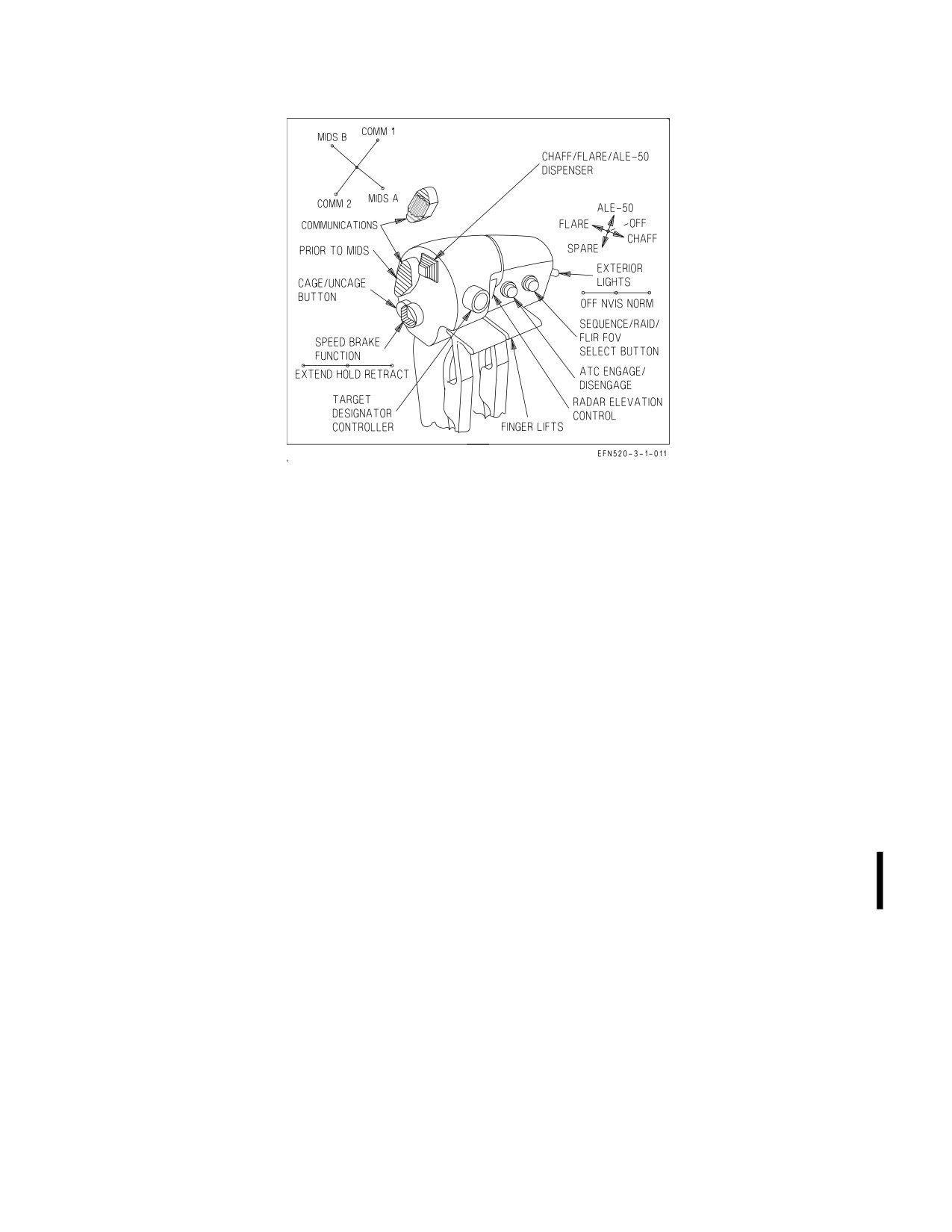
engine fuel control shutoff valves. The throttle grips (figure 2-1) contain switches that allow control of
various systems without moving the hand from the throttles.
2.1.1.4.3
Throttles
(Trainer Configured F/A-18F). The rear cockpit of the trainer configured
F/A-18F contains an additional set of flight controls: control stick, throttles, and rudder pedals. The
rear cockpit throttles, located on the left console, are mechanically connected to those in the front
cockpit and provide thrust modulation from IDLE to MAX. The rear throttles do not contain finger
lifts, so the engines cannot be secured from the rear cockpit. The rear throttle grips are slightly
different than those in the front cockpit. The ATC engage/disengage switch is not functional; the
I-2-6
ORIGINAL
A1-F18EA-NFM-000
Figure 2-1. Throttle Grips (Front Cockpit)
chaff/flare/ALE-50 switch is not installed; and the speed brake switch is momentary action only. In
general, systems controlled by throttle switches respond to the last crewmember action taken from
either cockpit.
2.1.1.4.4
EFD - Engine Fuel Display, Engine Parameters. The EFD, located on the main instrument
panel below the left digital display indicator (LDDI), is a night vision imaging system (NVIS)
compatible, monochromatic, liquid-crystal, grey/black display powered by the Signal Data Computer
(SDC).
The EFD normally displays critical engine parameters in the bottom half of the display and fuel
quantities in the top half. The fuel portion of the EFD is described in the Fuel System section. Invalid
parameters are usually displayed as 999 or 9999 in inverse video; out of limit parameters are always
highlighted by inverse video. Nozzle position is displayed both graphically and digitally in percent
open.
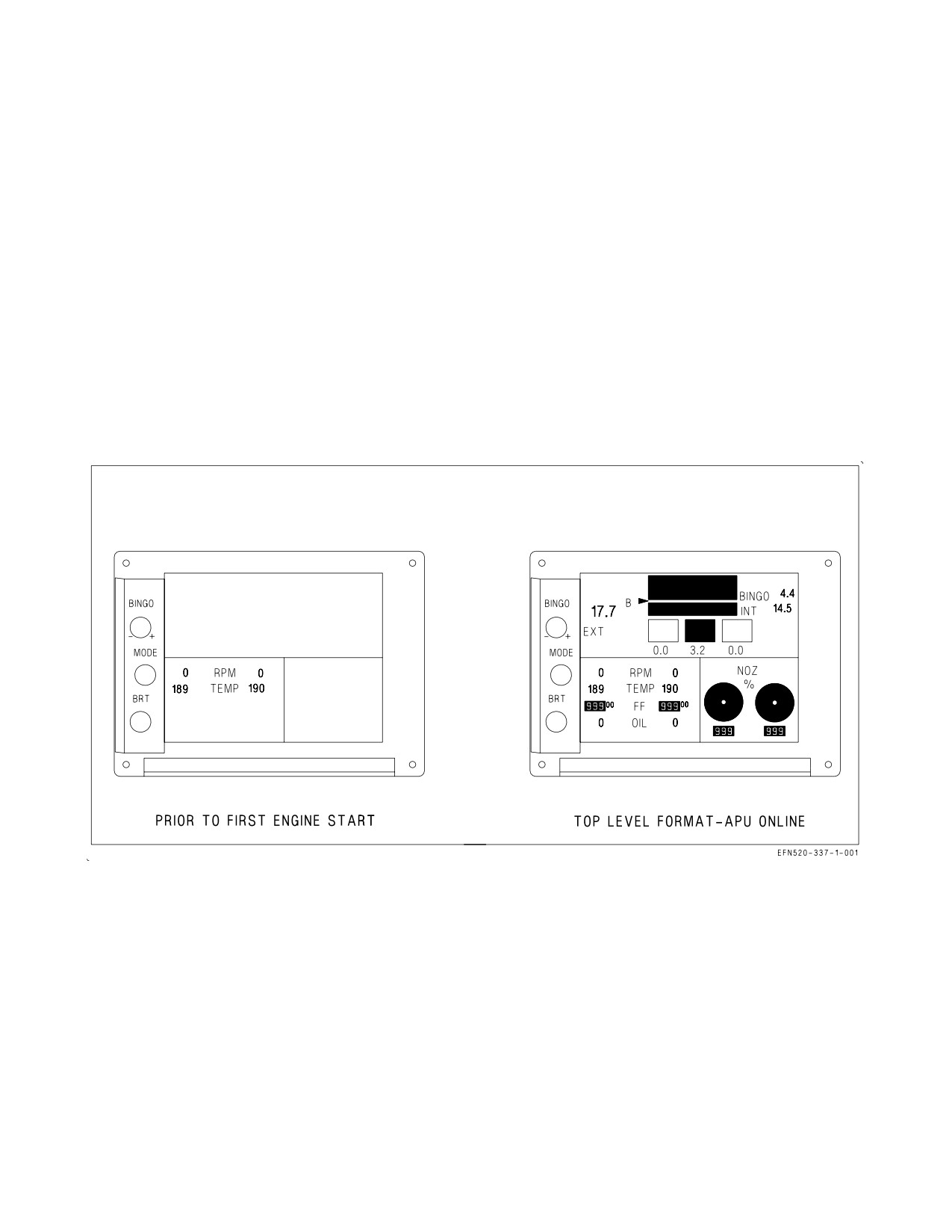
On battery power prior to APU start, the EFD either displays only RPM and TEMP or the entire
top level format (figure 2-2). If the entire top level format is not displayed on battery power, it will be
displayed when the APU switch is selected ON. When the APU switch is selected ON, only RPM,
TEMP, and OIL pressure are valid. When the first engine alternator comes online at 10% N2 rpm, the
FF parameter also becomes valid. When the first generator comes online at 60% N2 rpm, all
parameters for both engines become valid. If the EFD locks up or blanks completely during engine
start power transients, the display can be reset by selecting the SDC RESET option from the SUPT
MENU/FUEL display.
The EFD displays the following engine parameters within the listed display tolerances:
RPM Compressor rpm (N2 ) (0 to 127%) - Displays RPM in inverse video format above
102%
I-2-7
ORIGINAL
A1-F18EA-NFM-000
TEMP Compensated turbine exhaust gas temperature (EGT) (186 to 1,088°C) - Displays 9999
in inverse video above 1,100°C
FF
Total commanded fuel flow including afterburner (0 or 400 to 65,000 pph in 100 pph
increments).
NOTE
Engine fuel flow is calculated from commanded engine fuel metering
valve position. In failure modes, fuel flow can be indicated on the EFD
even though no actual fuel is flowing.
OIL
Oil pressure (0 to 200 psi)
NOZ VEN position (0 to 101% open)
Figure 2-2. Engine Fuel Display (EFD) - Engine Parameters
During first engine battery start, the EFD RPM indication typically jumps from 0 to either 5% or
10%, and lightoff is indicated by TEMP rising from a minimum reported value of approximately
190°C. Each engine has three sources of N2 rpm: two engine alternator sensors and one accessory
gearbox sensor. The accessory gearbox sensor can provide rpm readings down to only 5% and is the
initial source of engine RPM. Readings from the alternator sensors are not available until the
alternator comes online above 10% N2 rpm. Input for the TEMP parameter is provided by a
compensated EGT algorithm in the FADEC. When actual EGT is below accuracy tolerances (e.g.,
engine shutdown), the FADEC limits the minimum reported TEMP (approximately 190°C). The FF
parameter is a calculated number based on metering valve position, not an actual measurement of fuel
flow. Consequently, an indication of fuel flow may be present when there is no flow, such as when the
throttle is above IDLE with the engine off.
I-2-8
ORIGINAL
A1-F18EA-NFM-000
2.1.1.4.5
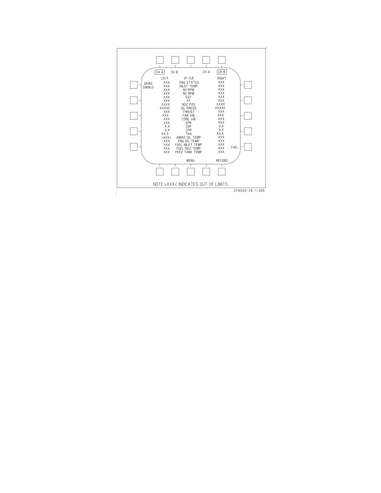
ENG Display. The ENG display (figure 2-3) is selected by pushing the ENG option from the
SUPT MENU. The ENG display shows the following engine and thermal management system
parameters:
ENG STATUS
The current level of engine performance provided by the control system
INLET TEMP
Engine inlet temperature (°C)
N1 RPM
Fan speed (% rpm)
N2 RPM
Compressor speed (% rpm)
EGT
Exhaust gas temperature (°C)
FF
Total commanded fuel flow (pph)
NOZ POS
Nozzle position (% open)
OIL PRESS
Engine oil pressure (psi)
THRUST
Takeoff thrust (%), referenced to hot day MIL power (blanked inflight)
FAN VIB
Fan vibration (inches/second)
CORE VIB
Core vibration (inches/second)
EPR
Engine pressure ratio (exhaust pressure to engine inlet pressure).
CDP
Compressor discharge pressure (psia)
CPR
Compressor pressure ratio
THA
Throttle handle angle (deg)
AMAD OIL TEMP
AMAD oil temperature (°C)
ENG OIL TEMP
Engine oil temperature (°C)
FUEL INLET
Engine inlet fuel temperature (°C)
TEMP
FUEL NOZ TEMP
Engine nozzle fuel temperature (°C)
FEED TANK
Feed tank fuel temperature (°C)
TEMP
When an engine or thermal management system related caution appears, the MENU option at the
bottom of each DDI is replaced with the ENG option, providing one pushbutton access to the ENG
display. The value of the out of limit parameter which triggered the caution is displayed in red and
highlighted by carets on either side. The CH A and CH B options at the top of the display are used to
command a manual FADEC channel transfer, and the active FADEC channel for each engine is boxed.
I-2-9
ORIGINAL
A1-F18EA-NFM-000
Figure 2-3. Engine Display
The selected fuel grade is displayed top center and also on the takeoff side of the CHKLIST display.
The FUEL option enables the JP-5, 8, and JP-4 options, each of which must be selected twice to change
the fuel grade. The fuel grade selected should reflect the majority of fuel in the aircraft. JP-5, -8 should
be selected when using JET-A, A+, or A1. The engines can be started and operated at ground idle with
either fuel grade selected; however, for operations above IDLE, the correct fuel grade must be selected
to ensure proper engine operation and to avoid engine combustor rumble. The fuel grade selected is
also used by the FADEC to control the thermal control valve (TCV) setting and determines the
maximum fuel temperature to be sent to the engines. Incorrect fuel grade selection can adversely
impact the fuel thermal management system and result in a premature FUEL HOT caution. The
RECORD option, boxed when selected, saves a 30 second record of display and engine data (15 seconds
pre- and 15 seconds post-event) to the memory unit (MU). The DFIRS DWNLD option downloads
DFIRS data to the MU.
2.1.2 ATC - Automatic Throttle Control. The ATC system has two operating modes: approach and
cruise. The system automatically modulates engine thrust between flight IDLE and MIL power in
order to maintain on-speed angle of attack (AOA) in the approach mode or calibrated airspeed
(existing at the time of engagement) in the cruise mode.
During ATC operation, engine commands are sent to the FADEC directly from the FCCs instead of
the throttles. FCC generated engine commands are limited to a range slightly above idle to slightly
below MIL. The throttles are continuously positioned by an FCC commanded backdrive unit to match
the throttles with the current engine command and to provide feedback to the pilot.
2.1.2.1
ATC Engagement. Pressing and releasing the ATC button on the left throttle engages the
approach mode with the FLAP switch in HALF or FULL and the cruise mode with the FLAP switch
in AUTO. When either mode is engaged, an ATC advisory is displayed on the HUD. Because ATC
mode engagement and ATC HUD advisories are not commanded until release of the ATC button, the
pilot may need to deliberately pause after press and release to avoid inadvertant ATC disengagement/
re-engagement. Automatic transition between the two modes or engagement during single engine
operation is not possible. Engaging ATC with the friction lever in the full aft position and with the
I-2-10
ORIGINAL
A1-F18EA-NFM-000
throttles at mid-range power provides optimum pilot feedback with the smallest engagement power
transients.
2.1.2.2
ATC Disengagement. If either mode does not engage when selected, or automatically
disengages after engagement, the ATC advisory flashes for 10 seconds and is removed from the HUD.
Disengagement for any reason requires reengagement to restore ATC operation. Normal disengage-
ment is accomplished by re-actuation of the ATC button or by applying a force of approximately 12
pounds (friction off) to either throttle for greater than 0.20 seconds. This force is sufficient to permit
the pilot’s hand to follow throttle movement without causing disengagement. Holding the throttles
against the MIL or IDLE stop during ATC disengagement commands a rapid acceleration or
deceleration to the commanded power setting instead of a smooth transition.
2.1.2.3
ATC Automatic Disengagement. The ATC system automatically disengages for the following
reasons:
Either mode -
• Any ATC system internal failure
• ATC button failure
• FADEC failure
• FCC CH 2 or CH 4 failure
• Backdrive failure
• THA split greater than 3° for more than 1 second
• FLAP switch position change between AUTO and HALF or FULL
Approach mode only -
• AOA, pitch rate, or Nz sensor failure
• Bank angle in excess of 70°
• Flap blowup at 250 KCAS
• Gain ORIDE selection
• Weight on wheels
Cruise mode only -
• FCC calibrated airspeed failure
2.1.2.4
ATC Related Cautions. The ATC FAIL caution is described
in
the
Warning/Caution/
Advisory Displays in Part V.
2.2 FUEL SYSTEM
The aircraft is fitted with four internal fuselage tanks (Tanks 1 through
4), two internal wing tanks
(left and right), two fuselage vent tanks, and two vertical vent tanks. Tanks 2 and 3 are engine feed
tanks while Tanks 1, 4, and the wing tanks are transfer tanks. Total fuel can be increased by the
carriage of up to four 480 gallon external fuel tanks on the centerline, inboard, and midboard pylons.
The aircraft can also be configured as an airborne tanker with the carriage of a centerline mounted air
refueling store (ARS). All tanks, internal and external, may be refueled on the ground through a
single-point refueling receptacle or inflight through the inflight refueling probe.
I-2-11
ORIGINAL
A1-F18EA-NFM-000
The aircraft’s fuel system is composed of the following subsystems: engine feed, motive flow, fuel
transfer, tank pressurization and vent, thermal management, refueling, fuel dump, fuel quantity
indicating, and fuel low level indicating. Refer to Fuel System, Foldout Section, for simplified
schematics.
2.2.1 Engine Feed System. Each engine feed system contains an airframe mounted accessory drive
(AMAD) driven motive flow/boost pump, a feed tank with an internal motive flow powered turbo
pump, and an engine feed shutoff valve. For survivability, the left and right feed systems are normally
separated but can be interconnected by a normally closed crossfeed valve and a normally closed feed
tank interconnect valve.
2.2.1.1
Motive Flow/Boost Pumps. Each AMAD drives a two-stage motive flow/boost pump. The
first stage supplies low pressure fuel to its respective engine mounted fuel pump, while the second stage
supplies high pressure fuel to the motive flow system. Fuel from the motive flow system is used to cool
accessories, power the feed tank turbo pumps and certain transfer/scavenge pumps, and control certain
transfer valves.
2.2.1.2
Feed Tanks. During normal operation, each engine receives fuel from separate fuel feed lines.
Tank 2 supplies fuel to the left engine; Tank 3 to the right. A motive flow powered turbo pump in each
feed tank supplies fuel to its respective motive flow/boost pump.
Each feed tank has a horizontal baffle which traps fuel, providing a minimum of 10 seconds of
negative g flight at MAX power. No sustained zero g capability is provided, and prolonged transitions
through zero g (greater than 2 seconds) may produce a L and/or R BOOST LO caution.
If a feed tank turbo pump fails, fuel is suction fed to the motive flow/boost pump. In this case, flight
at high altitude with high feed tank fuel temperatures may not supply enough fuel for high power
settings.
2.2.1.3
Feed Shutoff Valves. In the event of a fire or fuselage fuel leak, engine feed shutoff valves
provide the capability to isolate a fuel feed system immediately downstream of the feed tank. Pressing
the L or R FIRE warning light electrically closes the corresponding engine feed shutoff valve, isolating
that fuel feed system.
2.2.1.4
Crossfeed Valve. The crossfeed valve, normally closed, allows a single motive flow/boost
pump to feed both engines when boost pressure is lost on one side (e.g., single engine shutdown, a leak,
motive flow/boost pump failure, or feed tank depletion). A loss of boost pressure downstream of the
motive flow/boost pump sets the L or R BOOST LO caution and opens the crossfeed valve. An open
crossfeed valve allows the output from the good motive flow/boost pump to supply fuel to the opposite
engine at rates sufficient for at least MIL power.
Pressing the L or R FIRE warning light electrically closes (inhibits opening) the crossfeed valve,
isolating the two fuel feed systems.
2.2.1.5
Interconnect Valve. A feed tank interconnect valve, installed between Tanks 2 and 3, is used
to control gravity transfer/balancing between the two feed tanks. During normal operation, the dual
flapper-type valve is held closed by motive flow pressure on either side (left motive flow on the Tank
2 side and right motive flow on the Tank 3 side), and no fuel gravity transfers.
If motive flow is lost on one side (e.g., single engine shutdown), the valve opens to make sure that
feed tank fuel is available to the opposite engine. For instance, if motive flow is lost on the right side,
the Tank 3 side of the valve opens, allowing fuel to gravity transfer to Tank 2 anytime the Tank 3 fuel
I-2-12
ORIGINAL
A1-F18EA-NFM-000
level is higher. If Tank 3 has a fuel leak (e.g., battle damage), motive flow pressure on the Tank 2 side
of the valve prevents Tank 2 fuel from gravity transferring into the leak.
2.2.1.6
Feed Tank Balancing. The SDC incorporates feed tank balancing logic, designed to keep
Tanks 2 and 3 within 100 lb of each other. With a normally operating fuel system, balancing begins
after Tank 4 is effectively empty (less than about 300 lb) and the feed tanks begin to deplete below full.
If a feed tank imbalance reaches 100 lb, the SDC shuts off the corresponding Tank 4 scavenge pump
until the imbalance is 50 lb in the opposite direction. With WoffW, feed tank balancing continues until
either feed tank reaches FUEL LO level (approximately 1,125 lb). Feed tank balancing stops at FUEL
LO to make sure tank 4 fuel is transferred to both feed tanks in case one feed tank is damaged and is
leaking. After transitioning to WonW, balancing is reinitiated and continues until either feed tank is
below 300 lb.
In the event of a fuel transfer failure (e.g., a feed tank begins to deplete with fuel in Tank 4), feed
tank balancing begins when either feed tank drops below approximately 2,100 lb for 1 minute. This
mechanization attempts to minimize the effect of the fuel transfer failure by reducing the resulting
feed tank split.
2.2.1.7
Feed Tank Imbalance with One Engine at Idle. If one engine is intentionally reduced to
idle/low power or is commanded to IDLE by the FADEC, a higher rate of fuel depletion can be
expected from the ″good″ engine’s feed tank. At internal fuel weights below approximately 4,900 lb
(transfer fuel depleted), a fuel split can be expected to develop between the feed tanks (interconnect
valve is closed). If fuel burn continues to approximately 2,450 lb, the good engine feed tank depletes
and runs dry. The motive flow/boost pump output pressure on the good side drops, sets the L or R
BOOST LO caution, and opens the crossfeed valve. The good engine feeds from the opposite feed tank
through the crossfeed valve.
When driven by an idling engine, a motive flow/boost pump can support fuel flow up to 28,000 pph
through the crossfeed valve (MIL power fuel flow is approximately 12,000 pph at sea level, standard
day). If the fuel flow demand on the usable engine exceeds 28,000 pph (midrange afterburner), motive
flow/boost pump output pressure drops, setting the other BOOST LO caution, closing the crossfeed
valve, and starving the good engine. MAX power, single engine fuel flow is approximately 38,500 pph
at sea level, 0.2M, standard day (approach conditions).
Selecting afterburner on the good engine with its feed tank reading empty
results in engine flameout if fuel flow exceeds 28,000 pph.
The only way to balance a growing feed tank split is to shutdown the idling engine. This opens both
the interconnect and crossfeed valves. The risk of balancing is a loss of hydraulic and electrical
redundancy provided from the engine if left at idle.
2.2.2 Fuel Transfer System. The fuel transfer system, controlled by the SDC, is designed to keep the
feed tanks full or near full during normal engine operation. Fuel is routed from Tanks 1 and 4, the
internal wing tanks, and external fuel tanks, if installed, through three independent sets of transfer
lines. Additionally, the SDC schedules Tank 1 and 4 transfer to control fuel center of gravity (CG).
2.2.2.1
Fuel Transfer - Tanks 1 and 4. Fuel is transferred from Tanks 1 and 4 to the feed tanks by
two dual-speed electric transfer pumps, one in each tank. The low speed setting is used for normal
I-2-13
ORIGINAL
A1-F18EA-NFM-000
transfer. The high speed setting is used during high fuel flow conditions such as afterburner operation,
ARS replenishment, or fuel dump. The one exception to this is that the Tank 1 transfer pump remains
in low speed setting during afterburner operation. During normal operation, each pump pressurizes the
Tank 1 and 4 transfer line as long as its tank has transfer fuel available. The SDC shuts down the
electric transfer pumps when the respective tanks are dry (Tank 1 empty, Tank 4 approximately 300
lb).
Jet level sensors (JLS) in the feed tanks control the flow of transfer fuel from the Tank 1 and 4
transfer line. For instance, Tank 2 does not accept fuel until its fuel quantity drops to approximately
2,100 lb, uncovering the JLS and opening the transfer valve. Tank 2 accepts fuel until its fuel quantity
reaches approximately 2,450 lb, covering the JLS and closing the transfer valve. Therefore, during
normal operation, Tank 2 fuel level cycles between 2,100 and 2,450 lb as long as transfer fuel is
available (JLS cycling).
Flapper valves in Tanks 1 and 4 provide a backup gravity transfer capability in certain circum-
stances. The flapper valve in Tank 4 is free flowing, gravity transferring to Tank 3 any time the Tank
4 fuel level is higher. Therefore, Tank 4 tends to keep Tank 3 full (near 2,600 lb) until the Tank 4 fuel
level drops below that of Tank 3 (wing tank fuel depleted). The flapper valve in Tank 1 is controlled
by left motive flow. The valve can be opened by the SDC following a Tank 1 transfer pump failure or
by loss of motive flow (left engine shutdown).
Since the Tank 4 transfer pump is not located on the bottom level of the tank, two motive flow
powered scavenge pumps, one routed to Tank 2 and the other to Tank 3, are installed to transfer the
last 300 lb of Tank 4. With empty transfer tanks, an excessive feed tank fuel split following symmetric
engine operation may indicate a Tank 4 scavenge pump failure. There is no SDC monitoring of the
Tank 4 scavenge pumps.
The Tank 1 and 4 transfer pumps are also used to dump fuel through the dump valve and to transfer
fuel to the ARS through the ARS replenishment valve.
2.2.2.1.1
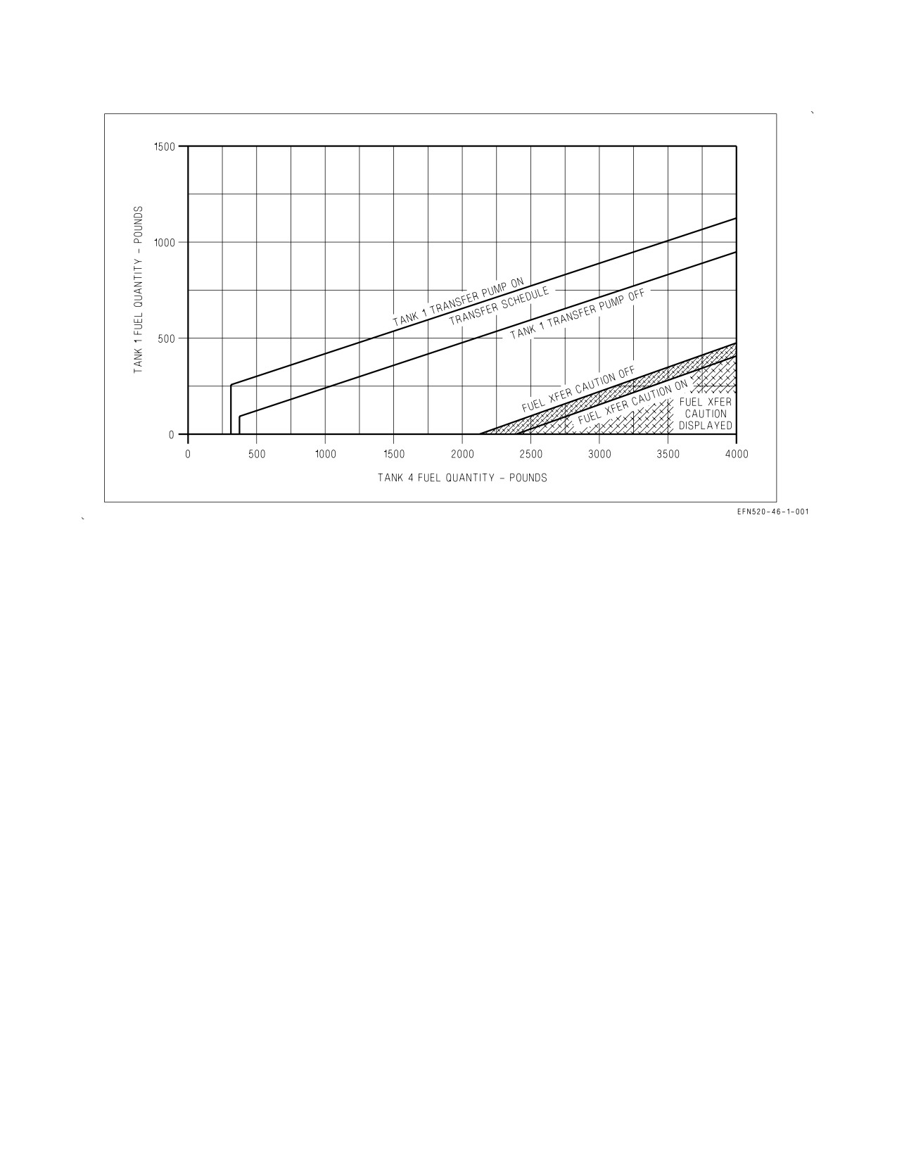
Fuel Transfer Schedule/CG Control. The SDC implements a fuel transfer schedule (figure
2-4) designed to keep aircraft CG at an optimum location. The system periodically shuts off the Tank
1 transfer pump to keep Tank 1 and Tank 4 properly balanced. Fuel transfer scheduling operates until
Tank 4 drops below 300 lb or the FUEL LO caution comes on. When Tank 4 reaches 300 lb, Tank 1
should indicate 250 lb or below.
The FUEL XFER caution is set when Tank 1 and 4 fuel is not scheduling properly or wing tank
imbalance exceeds 350 lb. The caution is inhibited when the inflight refueling probe is extended.
2.2.2.2
Fuel Transfer - Internal Wing Tanks. Fuel is transferred from the wing tanks to Tank 4 by
two motive flow powered ejector pumps, one in each tank. When Tank 4 is less than full, the SDC opens
both wing motive flow control valves, which direct motive flow to the ejector pumps and transfer fuel
from the wing tanks to Tank 4. When Tank 4 is full, the motive flow control valves are closed and
normal wing transfer is inhibited.
If motive flow is lost on one side (single engine shutdown), the cross-motive shutoff valve opens so
that one motive flow system can power the ejector pumps in both wing tanks. If both motive flow
systems are lost, the wing tanks gravity transfer to Tank 4. Bank angle changes or a steady sideslip may
be required to gravity transfer all available wing fuel.
2.2.2.2.1
Wing Tank Balancing. The SDC incorporates wing tank balancing logic designed to keep
wing tank asymmetry below 200 lb. If wing tank asymmetry exceeds 200 lb, the SDC shuts off fuel
I-2-14
ORIGINAL
A1-F18EA-NFM-000
Figure 2-4. Tank 1 and 4 Fuel CG Control and FUEL XFER Caution Schedule
transfer from the lower tank by closing its wing motive flow control valve. If wing tank asymmetry
exceeds 350 lb for 15 seconds, the FUEL XFER caution appears.
Wing tank balancing also occurs during refueling, where the SDC alternately opens/closes the wing
refuel valves attempting to keep the wing tanks within 200 lb. The FUEL XFER caution is not set
during refueling. If SDC balancing logic cannot keep the wings from refueling asymmetrically (greater
than 350 lb), the FUEL XFER caution is set when the inflight refueling probe is retracted.
2.2.2.2.2
INTR WING Control Switch. The INTR WING control switch, located on the EXT LT
panel on the left console, is used to isolate the wing tanks (e.g., following battle damage).
INHIBIT Prevents normal transfer and refueling of the wing tanks (closes both wing motive
control valves, both wing refuel valves, and switches both diverter valves, located
in Tank 3, from the wing tanks to the feed tanks).
NORM
Permits normal transfer and refueling of the internal wing tanks.
2.2.2.3
External Fuel Transfer. External fuel is transferred by regulated engine bleed air pressure
applied to all installed external tanks with WoffW. External tank pressurization is terminated for
inflight refueling (PROBE switch in EXTEND) and for arrested landing (both HOOK and LDG
GEAR handles down). With pressurization applied, external fuel transfer is controlled by the three
EXT TANKS transfer switches.
During external transfer, fuel is routed through the aircraft’s refuel/defuel line. Refuel valves in each
tank open only if commanded by the SDC and space is available. At MIL power and below, the SDC
I-2-15
ORIGINAL
A1-F18EA-NFM-000
only allows external fuel to transfer to Tank 1 and the wing tanks. In afterburner, the SDC allows
external fuel to transfer to any internal tank that can accept it.
NOTE
In Lots 21 - 25, SDC CG control logic (CG Restart) inhibits external
fuel transfer in flight and on deck with ORIDE selected until Tank 1
fuel quantity depletes to approximately 900 lbs. After external fuel
transfer begins, erroneous empty
(<200
lbs) external fuel quantity
readings, which may occur during climbs/dives, can reinitiate CG
Restart logic inhibiting external fuel transfer until Tank
1
fuel
quantity depletes again to approximately
900
lbs. To initiate
immediate external fuel transfer in flight or to check external fuel
transfer on deck (i.e., override CG Restart logic), the IFR probe must
be extended for at least 25 seconds prior to retraction with at least one
EXT TANKS switch in ORIDE.
2.2.2.3.1
EXT TANKS Transfer Switches. The three EXT TANKS transfer switches are located on
the FUEL panel on the left console and are labeled LM/RM, LI/RI, and CTR (left and right midboard,
left and right inboard, and centerline tanks, respectively). With the external tanks pressurized, fuel
transfers when the FUEL LO caution is displayed regardless of the position of the EXT TANKS
transfer switches.
ORIDE Applies pressurization and transfers fuel from all external tanks whose switches are not
in STOP. May be used to transfer external fuel during extended ground operations
(EXT TANK caution). Overrides any SDC stop transfer command.
NORM Permits normal transfer and refueling of controlled external tank(s).
STOP Prevents transfer and refueling of controlled external tank(s) except with a FUEL LO
caution.
NOTE
• For ARS configured aircraft: If fueling of the ARS is not desired during
aerial refueling, as the receiver, CTR ORIDE must be selected since
CTR STOP will not prevent fuel from entering the ARS. Selecting
CTR ORIDE will pressurize all external fuel tanks and significantly
reduce refueling rate.
• If the ARS control panel is installed, centerline external tank transfer
is inhibited unless the STORE switch is in FROM. ORIDE on the CTR
EXT TANKS switch will have no effect.
2.2.3 Fuel Tank Pressurization and Vent. In Lots 21 thru 23, the internal fuel tank pressurization
system provides regulated engine bleed air pressure to all internal tanks to prevent fuel boil-off at
altitude. Bleed air pressure is applied to all internal tanks with WoffW. Pressurization is terminated
for inflight refueling (PROBE switch in EXTEND) and for arrested landing (both HOOK and LDG
GEAR handles down). In Lots 24 and up, internal tank pressurization is supplied by ram air only from
the vertical tail vents and no longer augmented by engine bleed.
I-2-16
ORIGINAL
A1-F18EA-NFM-000
The vent system provides over-pressure and over-fill relief for the internal tanks. Pressurization is
applied to the vent lines in the two fuselage vent tanks. The vent lines connect all internal tanks and
are ported through the fuselage and vertical tail vent tanks to outlets located on the side of the vertical
tail. Normally, the vent lines contain only pressurized air; however, if a refuel valve failure overfills an
internal tank, fuel flows through the vent lines to the fuselage vent tanks. Two motive flow powered
vent tank scavenge pumps return this fuel from the fuselage vent tanks to the feed tanks.
Additionally, the vent system provides pressure relief of the internal fuel tanks during climbs and
vacuum relief during descents, if the pressurization system fails.
2.2.4 Thermal Management System. The thermal management system uses fuel from the high
pressure fuel stage of the motive flow/boost pump to cool the FADECs, liquid coolant, and AMAD and
hydraulic oils. The high pressure motive flow output of the pump has four branches.
The first branch is used to run motive flow powered pumps and valves in the fuel system. The second
branch directs cooling flow to the FADEC and exits into the fuel recirculation return line.
The third branch runs through the liquid coolant/fuel heat exchanger and the combined AMAD oil
and hydraulic oil/fuel heat exchanger in order to cool those fluids. A hot fuel diverter valve in the third
branch either directs fuel away from the engine and into the fuel recirculation return line or directs fuel
to the engines where it is combined with fuel feed from the motive flow/boost pump and burned.
Recirculated fuel first passes through a fuel/air heat exchanger bypass valve, which either directs the
fuel through or around the fuel/air heat exchanger. When sufficient recirculation fuel flow is present,
the SDC may open the heat exchanger bypass valve (Mach greater than approximately 0.35) to direct
hot fuel through the fuel/air heat exchanger. Then, the fuel passes through a diverter valve, located in
Tank 3, which either directs the fuel to the wing tanks or the feed tanks. Fuel directed to the wing tanks
then flows to Tank 4 for additional cooling. When Tank 4 is below 300 lb, recirculation fuel is returned
to the feed tanks by the Tank 4 scavenge pumps. When recirculation fuel is diverted to the wing tanks,
modulation of wing fuel quantities on cockpit fuel displays is noticeable at lower wing fuel levels.
The engine thermal control valve (TCV), located in the engine fuel control unit, maintains engine
combustor nozzle, engine lube oil, and aircraft accessories within their temperature limits. When the
system determines that more cooling is required (typically due to hot weather or low fuel levels), the
TCV opens, directing feed fuel into the recirculation return line. With the TCV open, greater cooling
flow is induced through the engine lube oil and aircraft accessory heat exchangers, and the FADEC,
ultimately reducing system temperatures.
The fourth branch runs to the cross cooling valve which opens following a motive flow system failure,
allowing one motive flow system to cool both FADECs and both engines’ accessories.
During ground operations, when temperatures exceed 40°C (30°C in LOT 26 and up), the liquid
coolant pump and Liquid Cooling System (LCS) ground cooling fan may be commanded on (if not
already on) to provide LCS cooling of the fuel system. In LOT 25 and below, the bypass valve, which
allows liquid coolant to the liquid coolant/fuel heat exchangers, is solely controlled by the liquid
coolant temperature, so the amount of fuel cooling provided (if any) depends on the temperature of
each fluid. In LOT 26 and up, the bypass valve is controlled by the ECS controller and will only direct
liquid coolant to the liquid coolant/fuel heat exchanger if the RADAR knob is in OFF.
NOTE
In LOT 26 and up, the RADAR knob must be in OFF in order to
provide any postflight LCS fuel cooling.
I-2-17
ORIGINAL
A1-F18EA-NFM-000
In either case, placing the RADAR knob to OFF removes the radar as a heat source and should
extend ground operating time.
2.2.4.1
Fuel/Air Heat Exchanger. A fuel/air heat exchanger is located above each engine inlet, near
the leading edge. When the heat exchanger bypass valve is open, the heat exchanger uses inlet air to
provide additional fuel cooling. Air is drawn from the inlet through several banks of small pin holes
(bleed plates) and is exhausted through the spoiler opening on the upper surface of the LEX/fuselage.
2.2.4.2
Fuel/Air Heat Exchanger Leak Detection. Since a leak in the fuel/air heat exchanger can
result in engine fuel ingestion through the bleed plates, a leak detection system is incorporated. If a fuel
leak is detected during fuel/air heat exchanger operation, the SDC closes the heat exchanger bypass
valve and isolates the heat exchanger.
Leak detection logic is only capable of detecting a leak greater than approximately 400 pph in the
fuel air heat exchanger. Fuel flow through the heat exchangers is inhibited below approximately Mach
0.35 and anytime the ECS auxiliary scoops are deployed to guard against potential for engine inlet fuel
ingestion.
A leak of less than 400 pph can, however, be discovered during the post-flight switching valve checks.
Following engine shutdown, the SDC opens the cross cooling valve and the heat exchanger bypass valve
on the non-operating side for 20 seconds. If ground crew observe fuel exiting from the fuel/air heat
exchanger drainage ports (bottom, inboard edge of the inlet), a leak exists.
2.2.5 Refueling System. The aircraft can be refueled on deck through a single point refueling
receptacle or inflight through a hydraulically actuated inflight refueling probe. The refueling
receptacle is located behind door 8R on the forward right fuselage. The refueling probe is located on
the upper right side of the fuselage forward of the windscreen. A fuel pressure regulator/surge
suppressor is installed downstream of the refueling probe in order to control pressure spikes associated
with inflight refueling. Fuel from the single point receptacle or the refueling probe enters the
refuel/defuel line and is routed to all internal and external tanks. During refueling, the SDC opens all
refuel valves, allowing fuel to transfer into all internal tanks. External tank pressurization is
terminated when the probe is extended, allowing the refuel/defuel line to fill all installed external tanks
(EXT TANKS switch(es) not in STOP).
2.2.5.1
PROBE Switch. The guarded PROBE switch, located on the FUEL panel on the left console,
is used to extend and retract the inflight refueling probe.
EXTEND Extends the inflight refueling probe using HYD 2A pressure, energizes the probe
light (external lights master switch in NORM), and depressurizes all internal and
external tanks.
RETRACT Retracts the inflight refueling probe using HYD 2A pressure, deenergizes the probe
light, and repressurizes the internal and external tanks. The probe cannot be
retracted if HYD 2A pressure is not available.
EMERG Emergency extends the inflight refueling probe using either HYD 2B or APU accu-
EXTD mulator pressure, energizes the probe light (external lights master switch in NORM),
and depressurizes all internal and external tanks.
2.2.6 Fuel Dump System. The fuel dump system allows all fuel except feed tank fuel to be dumped
overboard. The dump valve, controlled by the DUMP switch, is located in the Tank 1 and 4 transfer
line. With the dump valve open, the Tank 1 and 4 transfer pumps (high-speed setting) force fuel out
I-2-18
ORIGINAL
A1-F18EA-NFM-000
the dump outlet, located on the trailing edge of each vertical tail. Wing tank fuel is dumped by
transferring to Tank 4 with the INTR WING switch in NORM. External fuel is dumped by
transferring to Tanks 1 and 4 only with the EXT TANKS switch(es) in NORM or ORIDE.
NOTE
Anytime four external fuel tanks are loaded on wing stations (3, 4, 8,
and 9), selecting ORIDE on LI/RI external transfer switch will improve
dump performance and external transfer rate by commanding
simultaneous transfer of all external tanks vs. normal transfer sequence
(tanks on Stations 3/9 must be empty prior to tanks on Stations 4/8
transferring). Performing this function imposes airspeed limitations
defined in Figure 4-12.
Dump rate is typically in excess of two engine MAX power fuel flow, approximately 1,300 lb per
minute (78,000 pph). Fuel dumping continues until:
a. The DUMP switch is placed to OFF.
b. The BINGO caution comes on.
c. Tanks 1 and 4 are empty and all available fuel from internal wing and external tanks has been
depleted.
d. The FUEL LO caution comes on.
Simultaneous selection of fuel dump and afterburner during high AOA
maneuvering may ignite fuel and cause fuselage damage.
2.2.6.1
Fuel DUMP Switch. The lever locked fuel DUMP switch, located on the FUEL panel on the
left console, is spring loaded to the OFF position and electrically held in the ON position.
ON Opens the dump valve, allowing transfer tank and external tank fuel to be dumped.
The switch reverts to OFF with a BINGO or FUEL LO caution. With either caution,
holding the switch in the ON position with Tank 1 and/or 4 fuel available reinitiates
fuel dump.
OFF Dump valve closed
2.2.7 Fuel Quantity Indicating System. The fuel quantity indicating system measures the individual
fuel quantities in all internal and external fuel tanks and provides cockpit readouts for individual
tanks, total internal fuel, and total fuel onboard. Quantities are displayed on the EFD and the FUEL
display, rounded to the nearest 10 pounds (figure 2-5). Actual fuel tank probe readings are displayed
on the FUEL QTY display selected from the SUPT MENU/BIT/STATUS MONITOR display.
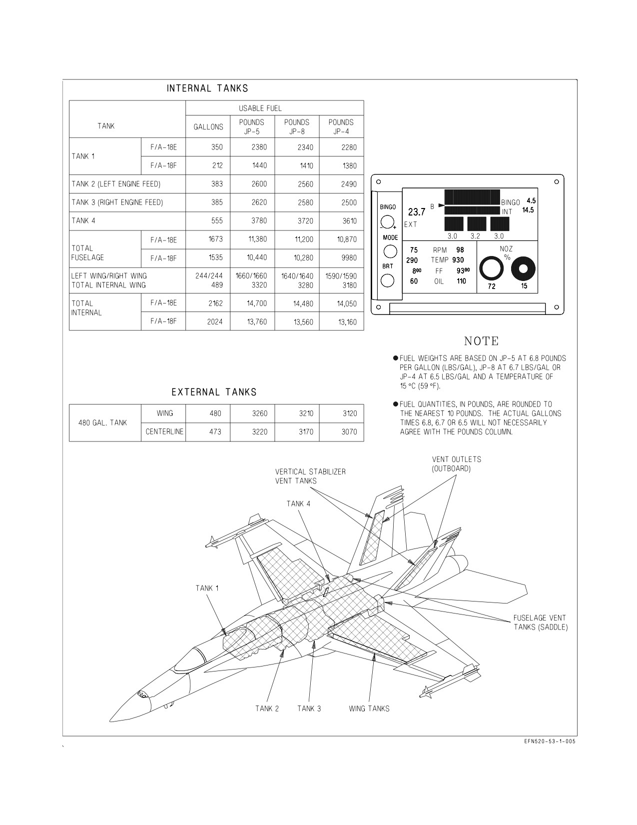
While the volume of fuel with full tanks does not change, the fuel quantities listed in pounds vary
with changes in temperature and fuel density. Full internal fuel quantity can vary from 13,250 to 15,960
lb for the F/A-18E or from 12,410 to 14,940 lb for the F/A-18F at fuel temperatures of 100° and -40°F,
respectively. Figure 2-5 lists standard day fuel quantities for JP-5, JP-8, and JP-4.
I-2-19
ORIGINAL
A1-F18EA-NFM-000
Figure 2-5. Fuel Quantity
I-2-20
ORIGINAL
A1-F18EA-NFM-000
2.2.7.1
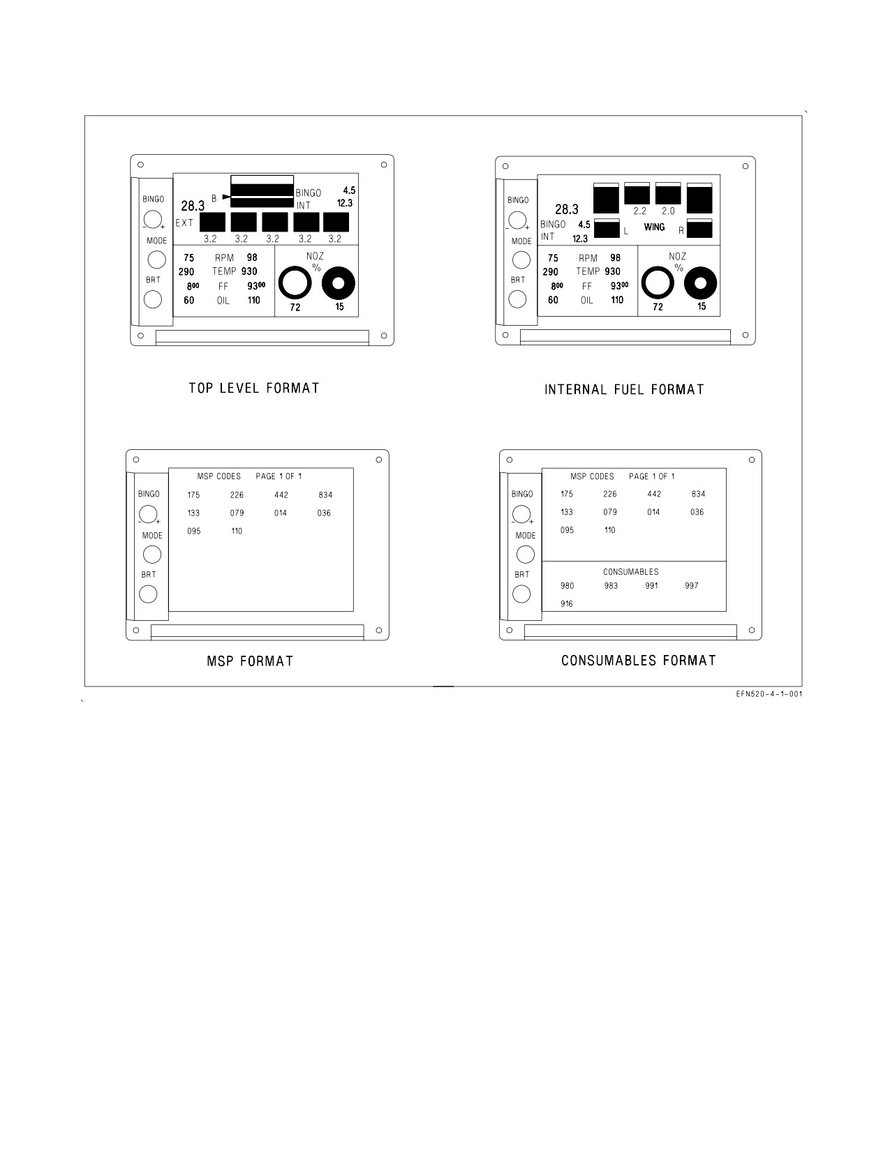
EFD - Engine Fuel Display, Fuel Parameters. The EFD displays fuel, maintenance code, and
consumables information in green digits on a black backg1round (figure 2-6). The top level EFD format
graphically displays total internal fuel, bingo level, and fuel quantities for up to five external fuel tanks.
The shaded regions of each graphic display the ratio of fuel available to fuel capacity. Digital readouts
of total fuel (large numbers), total INT fuel, external fuel tank quantities, and current BINGO setting
are also provided but are truncated to 100 lb increments.
The internal fuel format graphically displays only internal fuel tank quantities. Digital readouts of
feed tank fuel quantities are also provided, truncated to 100 lb increments.
During battery start of the engines, the EFD displays either three or five external fuel tanks if one
or more external fuel tanks are installed. For instance, if a full centerline tank is installed, the EFD
displays a full centerline graphic and 3.2 lb fuel. The inboard/midboard tanks appear empty reading
0.0 lb fuel. When the SMS completes startup BIT and initial inventory, the EFD displays only the
installed tank(s).
The aircraft fuel load can be checked on battery power by placing the ENG CRANK switch to L or
R, by starting the APU, or by resetting the MSP codes in the nose wheelwell. In the F/A-18F, the total
fuel load and the tank one fuel ratio will be in error, since the SDC defaults to F/A-18E settings while
on battery power. The total fuel load will appear 200 to 400 lb high, and the Tank 1 graphic (as
displayed on the internal format) will indicate approximately two-thirds when Tank 1 is, in fact, full.
When the MCs become operative with ac power applied, the total fuel load will be correct, and the EFD
will show the correct Tank 1 fuel ratio.
Bingo level is adjusted in hundred pound increments by rotation of the BINGO knob and thousand
pound increments by pull and rotation (clockwise is increasing). The MODE button toggles the EFD
between the top level and internal fuel formats. Pressing the MODE button for greater than 1.5
seconds selects the MSP format. With the MSP format displayed, the BINGO knob cycles between
MSP code pages if more than one is present. Pressing the MODE button again for greater than 1.5
seconds runs and displays the results of a consumables test. Subsequent actuation for less than 1.5
seconds returns to the last displayed top level or internal fuel format. Clockwise rotation of the BRT
knob increases the display’s brightness.
In the F/A-18F, the formats can be displayed on the aft EFD independently from the front EFD.
2.2.7.2
FUEL Display. The FUEL display (figure 2-7) is selected by the FUEL option on the SUPT
MENU. The FUEL display lists TOTAL fuel (internal and external), total INTERNAL fuel, the
available fuel in each tank, and the current BINGO setting. A moving caret is shown on the right side
of each tank, indicating the ratio of fuel available to tank capacity.
The SDC continuously monitors the validity of the fuel probes installed in each tank. If all probes
in a tank (except the feed tanks) are declared invalid, the SDC displays 0 lb fuel and the INV (invalid)
cue next to the tank. If one or more probes in a multi-probe tank are declared invalid, the SDC displays
the total of the valid probes only and the EST (estimated) cue next to the tank. If a feed tank fuel probe
is invalid, the SDC displays 1,125 lb (0 lb if the FUEL LO caution is set) and the EST cue. The TOTAL
and INTERNAL fuel values indicate the sum of all valid and estimated tank quantities with EST cues
(INV cues if any tank is INV).
The FLBIT option on the FUEL display is used to initiate a BIT of the fuel low level indicating
system. The FLBIT option remains boxed during BIT. A satisfactory test results in a FUEL LO
caution and voice alert within 13 seconds of BIT initiation. FLBIT cannot be initiated with a FUEL
I-2-21
ORIGINAL
A1-F18EA-NFM-000
Figure 2-6. Engine Fuel Display (EFD) - Fuel Parameters
LO caution set or an SDC failure. An SDC RESET option is provided to command an SDC software
reset.
2.2.7.3
F-QTY Advisory. The F-QTY advisory indicates an SDC or fuel quantity indicating system
failure which affects the accurate display of fuel quantity or CG information. The advisory is activated
when:
a. The MC loses communication with the SDC.
b. The SDC reports an internal or gauging system failure.
c. Any tank quantity is INV.
d. The SDC reports its output discretes are not working.
If a F-QTY advisory results from loss of MC communication with the SDC or the SDC reporting an
internal or gauging system failure, the MC is unable to report actual fuel quantities and the following
are displayed on the FUEL display (GLIM 7.5G caution):
I-2-22
ORIGINAL
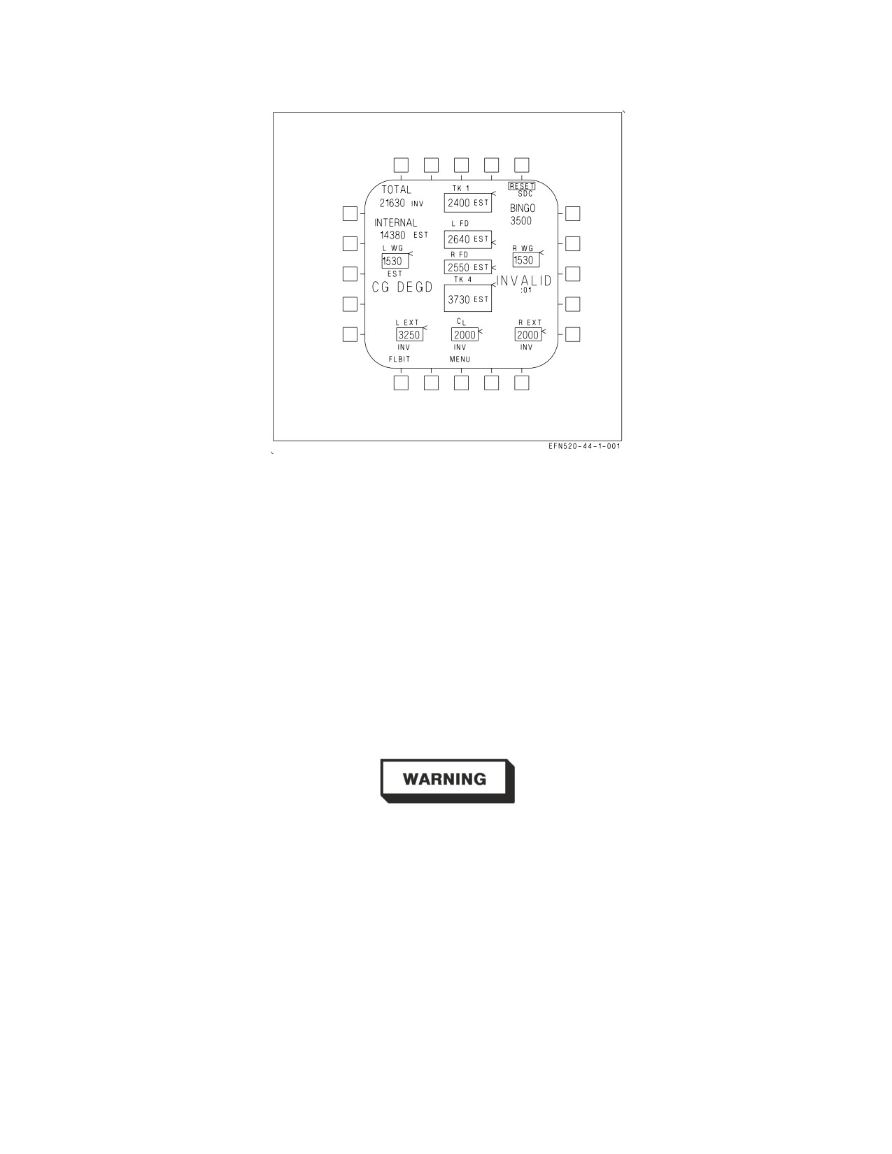
A1-F18EA-NFM-000
Figure 2-7. FUEL Display
a. All fuel quantities (except TOTAL) are held at their last displayed value.
b. TOTAL fuel is estimated by the MC based on the last valid fuel quantity and engine fuel flow.
c. A flashing ESTIMATED cue is displayed along with a minutes and seconds (XX:XX) timer
which indicates the duration since the displayed fuel quantities were last updated.
2.2.8 Fuel Low Level Indicating System. The fuel low level indicating system is completely
independent of the fuel quantity indicating system. When the fuel level in either feed tank drops to
approximately 1,125 lb, a FUEL LO caution, caution light, and voice alert are activated, and the
affected fuel tank quantity is displayed in inverse video on the EFD. If a low level indication was set
by a transient condition, such as prolonged negative g flight, the cautions remain on for 1 minute after
the low level indication is removed.
If the FUEL LO cautions are set, assume that at least one feed tank is
below approximately 1,125
lb regardless of displayed fuel quantity
indications.
I-2-23
ORIGINAL
A1-F18EA-NFM-000
2.2.9 Fuel System Related Cautions. The following fuel system related cautions are described in the
Warning/Caution/Advisory Displays in Part V:
D L or R BOOST LO
D L or R THERMAL
D L or R FUEL HOT
D FADEC HOT (WonW, IDLE or above)
D L or R FUEL INLT
D PROBE UNLK
D FUEL XFER
D REFUEL DR
D EXT XFER
D DUMP OPEN
D EXT TANK
D FUEL LO caution, caution light, and voice alert
D TK PRES LO
D BINGO caution and voice alert
D TK PRES HI
2.3 FPAS - FLIGHT PERFORMANCE ADVISORY SYSTEM
NOTE
FPAS is functional in MC OFP H1E AND UP.
The flight performance advisory system (FPAS) is provided to aid the pilot in making time, fuel, and
distance calculations. Readouts for maximum range and maximum endurance are provided for three
flight conditions: current Mach and altitude, optimum Mach at the current altitude, and optimum
Mach and altitude. These three readouts can be used to adjust the aircraft flight profile to meet
mission requirements. Additionally, FPAS provides fuel remaining at arrival and recommended
distance to begin descent from the selected waypoint or TACAN station. Range, time, altitude, Mach,
and fuel are calculated by the FPAS algorithm and appear on the FPAS display.
2.3.1 FPAS Display. The FPAS display (figure 2-8) appears when the FPAS option is selected from
the SUPT MENU. The display is divided into five areas: the current range and endurance area, the
waypoint/TACAN steering area, the fuel flow area, the optimum range and endurance area, and the
default area. With engines running and WonW, only the optimum and default areas are valid. With
WoffW, all five areas are valid. Waypoint/TACAN steering information is provided with WoffW and
waypoint or TACAN steering selected (boxed) on the HSI display.
2.3.1.1
FPAS CURRENT RANGE and ENDURANCE. The CURRENT RANGE area displays three
calculations: the range in nautical miles TO 2000 LB fuel remaining at the current altitude and Mach,
the BEST MACH to fly at the current altitude to maximize range, and the range TO 2000 LB fuel
remaining if the BEST MACH is flown. If parameters used to calculate current range become invalid,
X’s replace the current range value, and an FPAS advisory replaces the current endurance value.
The CURRENT ENDURANCE area displays three calculations: the time in hours and minutes TO
2000 LB fuel remaining at the current altitude and Mach, the BEST MACH to fly at the current
altitude to maximize endurance, and the endurance TO 2000 LB fuel remaining if the BEST MACH
is flown. If parameters used to calculate current endurance become invalid, X’s replace the current
endurance value.
If IMN exceeds Mach 0.9, a MACH advisory replaces the current range value, and a LIM advisory
replaces the current endurance value. When total fuel drops below 2,500 lbs, the FPAS calculations
shift to 0 lbs remaining, and the TO 2000 LB legend changes to TO 0 LB.
2.3.1.2
FPAS Waypoint/Tacan Steering and the HSI Display. If waypoint or TACAN steering is
selected (boxed) on the HSI display, the selected waypoint or TACAN station is displayed under the
NAV TO legend, and the arrival time and fuel remaining at arrival (at the current flight conditions)
are displayed under the TIME and FUEL REMAIN legends, respectively.
I-2-24
ORIGINAL
A1-F18EA-NFM-000
Fuel remaining at arrival and recommended distance to begin descent from the selected steering
source are displayed on the HSI display. If the recommended distance to begin descent is greater than
99 miles, 99 is displayed.
If FPAS waypoint/TACAN steering parameters become invalid, X’s replace the fuel remaining and
descent distance values. If IMN exceeds Mach 0.9, fuel remaining values are blanked. If fuel remaining
at the selected steering source is less than the TO 2000 LB or TO 0 LB legend, the WYPT number, the
TO 2000 (0) LB legend, and the fuel remaining value flash on the FPAS display and the fuel remaining
value flashes on the HSI display. If fuel remaining is calculated to be less than 0 lbs, 0 is displayed.
2.3.1.3
FPAS Fuel Flow. The total fuel flow rate (both engines) is displayed in pounds per nautical
mile under the LB/NM legend whenever the engines are running.
2.3.1.4
FPAS OPTIMUM RANGE and ENDURANCE. The OPTIMUM RANGE area displays three
calculations: the optimum ALTITUDE and MACH to fly to achieve the displayed maximum range TO
2000 LB. If parameters used to calculate optimum range become invalid, X’s replace the altitude,
Mach, and range values.
The OPTIMUM ENDURANCE area displays three calculations: the optimum ALTITUDE and
MACH to fly to achieve the displayed maximum endurance time TO 2000 LB. If parameters used to
calculate optimum range or optimum endurance become invalid, X’s replace the altitude, Mach, range,
and time values.
When total fuel onboard drops below 2,500 lbs, the FPAS calculations shift to 0 lbs remaining, and
the TO 2000 LB legend changes to TO 0 LB.
2.3.1.5
FPAS Default Area. If outside air temperature, stores drag, or fuel flow become invalid, the
TEMP, DRAG, or FF advisories are displayed next to the DEFAULT legend. These parameters, if
invalid, do not have a fatal impact on FPAS calculations.
2.3.2 FPAS CLIMB Option. The CLIMB option is available for selection in the NAV master mode.
Pressing the CLIMB option on the FPAS display enables the climb airspeed prompt, displayed above
the airspeed box in the HUD (HUD reject switch in the NORM position). When selected, CLIMB is
boxed and the climb airspeed prompt indicates the desired calibrated airspeed for an optimum climb
profile.
2.3.3 FPAS HOME Waypoint Selection. The HOME option arrows are used to increment/decrement
the home waypoint for use in FPAS fuel-on-deck (HOME FUEL caution) calculations. The selected
home waypoint is displayed above the HOME legend on the FPAS display. The home waypoint
defaults to 0 at power up and must be changed if another waypoint is desired (0 to 59). Decrementing
the home waypoint from 0 selects 59. If invalid parameters prevent FPAS from calculating the HOME
FUEL caution, the FPAS DDI advisory is displayed, the home waypoint is X’d, and the option arrows
are removed.
2.3.4 FPAS HOME FUEL Caution. When FPAS calculated fuel remaining at the selected home
waypoint reaches 2,000 lbs, the HOME FUEL caution is displayed. HOME FUEL caution logic is
disabled with WonW, the refueling probe extended, the landing gear cycled down then up, or within
5 seconds after a home waypoint change.
I-2-25
ORIGINAL
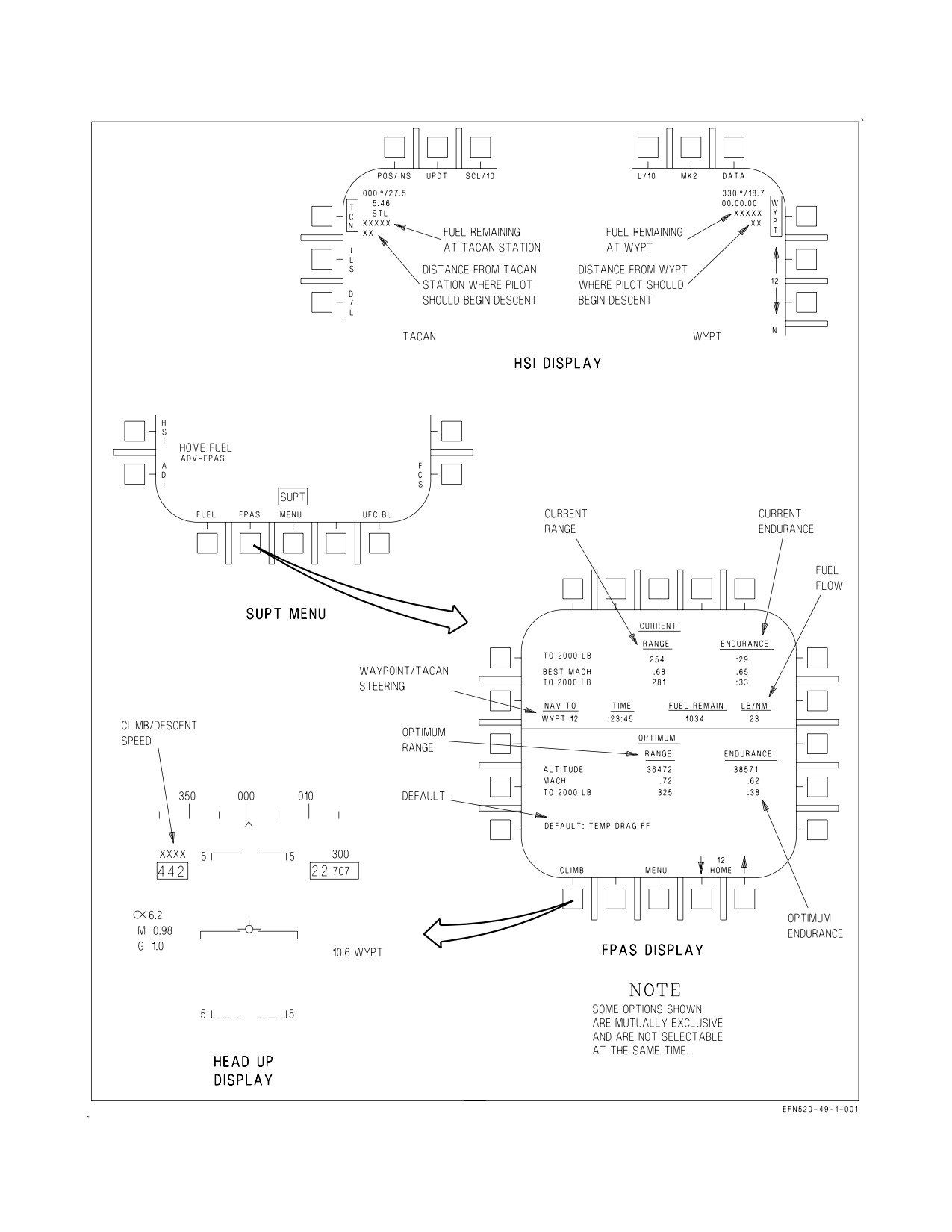
A1-F18EA-NFM-000
Figure 2-8. FPAS Displays
I-2-26
ORIGINAL
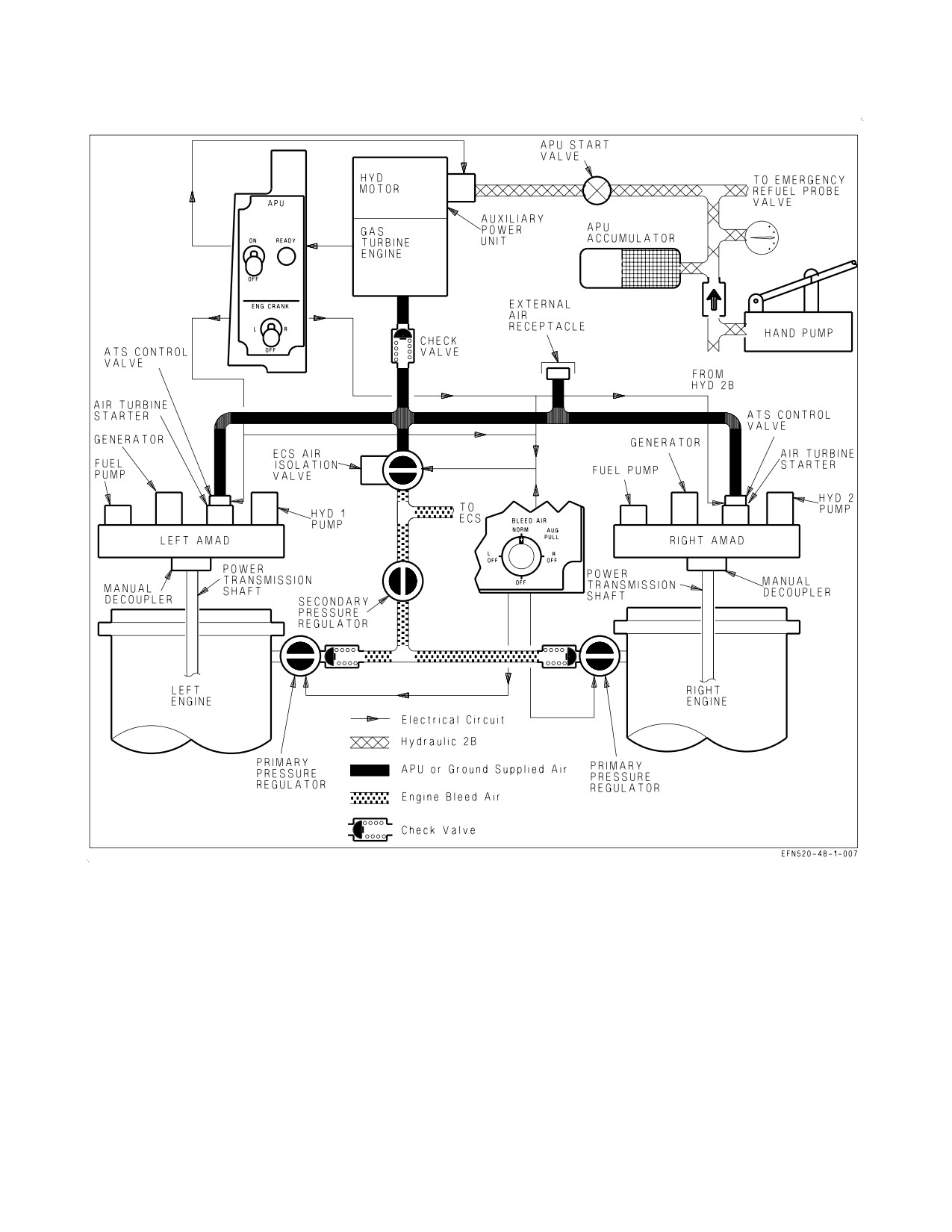
A1-F18EA-NFM-000
Figure 2-9. Secondary Power Supply
2.4 SECONDARY POWER SYSTEM
The aircraft secondary power system contains two airframe mounted accessory drives (AMAD) and
a single auxiliary power unit (APU). Figure 2-9 shows the major components of the secondary power
system.
2.4.1 AMAD - Airframe Mounted Accessory Drive. During normal operation, each AMAD is
mechanically driven by its corresponding engine through a power transmission shaft and is used to
drive a fuel boost/motive flow pump, an ac/dc electrical generator, and a 3000/5000 psi hydraulic pump.
Pneumatic pressure is used to rotate an air turbine starter (ATS) on each AMAD for engine crank/start
capability.
I-2-27
ORIGINAL
A1-F18EA-NFM-000
For ground maintenance use, either AMAD can be decoupled from its engine, allowing pneumatic
pressure to drive the AMAD and its accessories.
NOTE
Failure of the power transmission shaft (PTS) results in the display of
the associated GEN, BOOST LO, and both HYD circuit cautions.
2.4.2 APU - Auxiliary Power Unit. The APU is a small gas turbine engine used to generate a source
of air to power the ATS for normal engine start or to provide an alternate air source for the
environmental control system (ECS). The APU is located between the engines, with intake and exhaust
facing downwards.
The aircraft battery provides electrical power for APU ignition and start. A hydraulic motor powered
by the APU accumulator is used to start the APU. The APU receives fuel from the left engine feed line
upstream of the left engine feed shutoff valve. During normal operation, the APU shaft turns a
separate compressor which supplies air for main engine start or alternate ECS operation.
If an APU fire or overheat condition is detected on the ground, the APU fire extinguishing system
automatically shuts the APU down and, after 10 seconds, discharges the extinguisher bottle.
2.4.3 APU Switch. The APU switch, located on the left console, is spring loaded to the OFF position
and is electrically held in the ON position.
ON Automatic start and normal APU operation. The switch returns to OFF 1 minute after
the second aircraft generator comes online (BLEED AIR knob not in AUG PULL).
OFF Manual APU shutdown
To prevent an APU running engagement and to prevent APU exhaust
torching, a minimum of 2 minutes must elapse between APU shutdown
and another APU start.
2.4.3.1
APU READY Light. The APU READY light, located on the left console adjacent to the APU
switch, comes on when the APU has completed the start cycle and is capable of supporting engine
crank.
2.4.4 ATS Air Sources. Pneumatic pressure from one of three sources can be used to power the ATS
for engine crank/start: APU compressor air, opposite engine bleed air (crossbleed), or external air.
The APU compressor is the primary engine crank air source. With the APU online, the ECS air
isolation valve is closed and the ENG CRANK switch opens the desired air turbine starter control valve
(ATSCV), allowing APU compressor output to turn the ATS, AMAD, and engine core.
A crossbleed start can be utilized when one engine is operating and the APU is shutdown. The
operating engine should be set to a minimum of 80% N2 rpm to make sure bleed air output is sufficient
to crank the opposite engine. For a crossbleed start, the ENG CRANK switch opens the ECS air
isolation valve and the ATSCV, allowing compressor bleed air pressure to turn the ATS, AMAD, and
engine core. If one engine fails inflight and the engine core is rotating freely, crossbleed air may be used
I-2-28
ORIGINAL
A1-F18EA-NFM-000
to rotate the AMAD and retain some fuel, electrical, and hydraulic system output.
ATS exhaust may blister paint and cause possible door damage on the aft
underside of the fuselage during extended crossbleed operation of a failed
engine.
An external air source may also be used to start one or both engines. External air is applied to the
aircraft through a connection in the right main wheelwell. Both engine bleed air valves must be closed
(BLEED AIR knob OFF) to make sure that external air is the sole air source for engine start. For an
external air start, the ENG CRANK switch opens the ATSCV, allowing external air pressure to turn
the ATS, AMAD, and engine core.
2.4.4.1
ATS Protection. Each ATS has two sources of overspeed cutout protection. The primary
source is the corresponding generator, and the backup source is the frequency sensing relay (FSR). The
FSR monitors ATS speed and provides the signal which electrically holds the ENG CRANK switch.
When the generator comes on the line at 60% N2 rpm, it removes power from the ATSCV and the FSR,
which releases the ENG CRANK switch. If the primary cutout does not function (GEN switch OFF or
major generator malfunction), the FSR releases the ENG CRANK switch when it senses 63% N2 rpm.
Regardless of the engine start air source utilized, the corresponding GEN
switch should be ON, as the generator provides primary overspeed cutout
protection for the ATS.
2.4.4.2
ENG CRANK Switch. The ENG CRANK switch, located on the left console, is spring loaded
to the OFF position and is electrically held in the L or R position.
L
Opens the left ATSCV and/or the ECS air isolation valve to direct pneumatic pressure
to the ATS for left engine crank.
OFF Closes both ATSCVs and the ECS air isolation valve. When the left or right generator
comes online following engine start, the switch automatically returns from L or R to the
OFF position.
R
Opens the right ATSCV and/or the ECS air isolation valve to direct pneumatic pressure
to the ATS for right engine crank.
2.4.5 AUG PULL. During extended ground operations, APU compressor air may be used instead of
engine bleed air to run the ECS and cool the avionics (BLEED AIR knob in AUG PULL). AUG PULL
operation is discussed in the ECS section.
2.4.6 AMAD Related Cautions. The following AMAD related cautions are described in the Warning/
Caution/Advisory Displays in Part V:
• L or R OIL HOT
• L or R AMAD PR
• L or R ATS
I-2-29
ORIGINAL
A1-F18EA-NFM-000
2.5 ELECTRICAL POWER SUPPLY SYSTEM
The electrical power supply system consists of two generators, two transformer-rectifiers (TR), one
battery with dedicated battery charger, and a power distribution (bus) system (figure 2-10). Each
generator provides a primary ac source and three isolated dc sources from a permanent magnet
generator (PMG). During normal operation, the left generator powers only the left buses while the
right generator powers only the right buses. If one generator fails, the other generator is capable of
carrying the entire electrical load of the aircraft. Battery power is provided for normal engine start.
External electrical power can be applied to power the entire system on the ground. The bus system
consists of the left and right 115 vac buses, right 26 vac bus, left and right 28 vdc buses, 28 vdc essential
bus and a 28 vdc maintenance bus. See figure 2-10 for a simplified schematic and Electrical System,
foldout section, for the specific systems powered by each bus.
2.5.1 Electrical RESET Button. The electrical system RESET button is located on the electrical
power panel on the right console. This button provides master reset capability for any failed generator
or electrical system relay without interrupting operational circuits.
2.5.2 AC Electrical Power. The two generators are the primary source of ac electrical power. With the
GEN switch in NORM, each generator comes online at approximately 60%N2 rpm as long as voltage
and frequency are within limits. Each generator supplies ac power to an independent 115 vac bus. In
addition, the right 115 vac bus powers a 26 vac bus through a dedicated transformer.
2.5.2.1
GEN Switches. Two generator control switches, labeled L GEN and R GEN, are located on
the electrical power panel on the right console.
NORM
Provides normal generator operation.
OFF
Removes the generator ac source from the bus system.
2.5.2.2
Electrical Fault Protection Circuitry. The electrical system provides fault protection with
generator isolation, bus tie, generator automatic reset, and ac bus isolation circuitry.
If a generator fault occurs, generator isolation circuitry removes the affected generator from its buses
(L or R GEN caution and caution light). All generator faults except N2 underspeed require manual
generator reset (GEN switch cycled to OFF then NORM or RESET button pressed). Generator reset
is successful only if the out-of-tolerance or fault condition has cleared. If the generator fault remains,
bus tie circuitry allows the remaining generator to power all electrical buses. During an N2 underspeed
condition, the affected generator is automatically restored when rpm returns to normal range.
If a short or overload condition (bus or equipment fault) occurs on a bus (the R 115 vac bus, for
instance), the following sequence is initiated. The right generator attempts to power through the short
and, if unsuccessful, trips offline. The left generator is then connected to the right buses by the bus tie
circuitry, attempts to power through the short, and, if unsuccessful, also trips offline. Approximately
1 second after the dual generator outage, the generator automatic reset logic resets both generators. If
the bus or equipment fault has cleared, both generators remain online to power their respective buses.
If the bus or equipment fault remains, the right generator trips offline again, but bus isolation circuitry
now prevents the left generator from picking up the right buses (GEN TIE caution light). The left
generator remains online to power the left buses and the R 28 vdc bus. The R 115 vac bus, R 26 vac bus,
and battery charger are unpowered, and the battery runs the maintenance bus. This entire process may
take as long as 16 seconds.
I-2-30
ORIGINAL
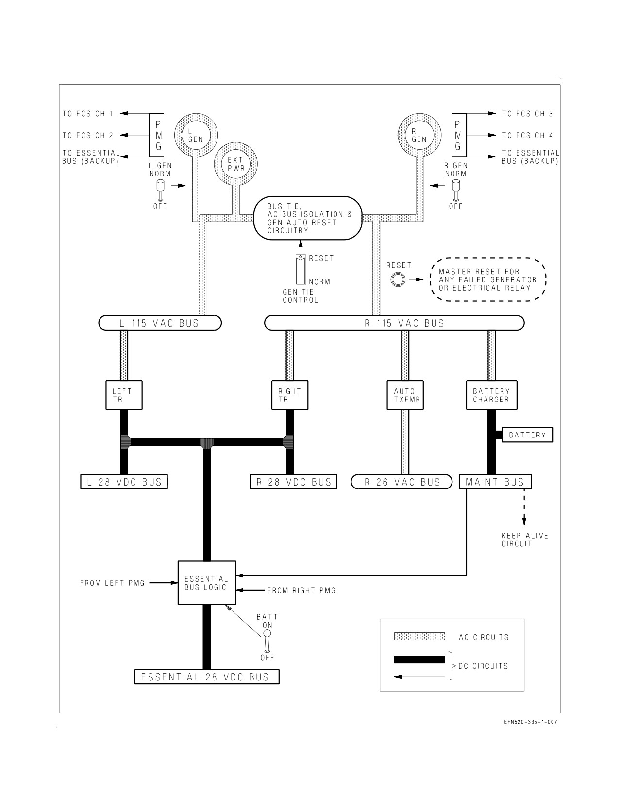
A1-F18EA-NFM-000
Figure 2-10. Simplified Electrical Schematic
I-2-31
ORIGINAL
A1-F18EA-NFM-000
For the ac bus isolation and generator automatic reset circuits to operate, the GEN TIE switch must
be in NORM, the BATT switch must be ON and the PARK BRAKE handle must not be set. With the
PARK BRAKE handle set, the generators do not reset following a dual outage.
2.5.2.3
GEN TIE Caution Light. During initial engine start (battery or external power) GEN TIE
circuitry requires a set PARK BRAKE handle to properly function. If the PARK BRAKE handle is not
set during right (first) engine start, a GEN TIE caution light comes on when the right generator comes
online. For a battery start, setting the PARK BRAKE handle and cycling the R GEN switch reties the
left and right buses and clears any avionics faults that would otherwise occur. For an external power
start, setting the PARK BRAKE handle, disconnecting external power, and cycling the GEN TIE
switch reties the left and right buses.
2.5.2.4
GEN TIE Switch. The red-guarded GEN TIE switch is located on the left console outboard of
the exterior lights panel.
RESET
Resets the bus tie circuitry. Reset is accomplished by cycling the switch to RESET
then NORM.
NORM
With the BATT switch ON, enables the bus tie, ac bus isolation and generator
automatic reset circuits.
If the left and right buses are isolated because of a detected fault (e.g., R
GEN caution and GEN TIE caution light), cycling the GEN TIE switch
reenergizes the faulty bus/equipment and may cause further damage or
loss of the remaining generator.
2.5.3 DC Electrical Power. DC electrical power is provided by two TRs, three dc outputs from each
PMG, the battery, and the battery charger.
2.5.3.1
TR - Transformer-rectifiers. While each TR is powered by its respective 115 vac bus, the
output of each TR is connected in parallel, powering both the left and right 28 vdc buses and providing
primary power for the essential bus. If one TR fails, the other powers the entire dc system. There is no
cockpit warning of a single TR failure (no caution and no MSP code). TR operation is checked on
maintenance phase inspections.
2.5.3.2
PMG - Permanent Magnet Generator. The PMG in each generator provides three dc sources,
two for FCC channels and one for essential bus backup. The left PMG provides the primary power
source for FCC A (channels 1 and 2), while the right PMG provides the primary power source for FCC
B (channels 3 and 4). Regardless of generator control switch position, the PMGs come online when the
engine reaches approximately 50% N2 rpm on spool up and remain on until 20% N2 rpm on spool
down.
2.5.3.3
Battery. The primary operational use of the battery is engine start. The battery powers the
maintenance bus directly, allowing operation of the canopy, ladder, and maintenance monitor in the
absence of ac electrical power. With the BATT switch ON (first engine start), the battery also powers
the essential bus. In the unlikely event of a total ac/dc failure inflight, the battery provides the last
level of essential bus backup capability, providing about 5 to 10 minutes of power for the FCCs, after
which aircraft control is lost.
I-2-32
ORIGINAL
A1-F18EA-NFM-000
Regardless of BATT switch position, the battery charger supplies charging power to the battery
anytime the right 115 vac bus is energized.
2.5.3.4
FCC Electrical Redundancy. FCC electrical redundancy is provided by several sources of dc
power (figure 2-11). The primary dc source for each FCC channel is its respective PMG output. If a
PMG output should fail, that FCC channel is powered by the essential bus, which also has several
sources of redundancy (the TRs, the PMGs, and the battery). The BATT switch must be ON for either
a PMG or the battery to power the essential bus. Additionally, ‘‘keep alive’’ circuits connected directly
to the maintenance bus provide each FCC channel with an uninterrupted backup power source during
normal bus power transients.
2.5.3.5
BATT Switch. The BATT switch is located on the electrical power panel on the right console.
ON
Allows the battery or either PMG to power the essential bus when TR power is not
available.
OFF
Prevents the battery or either PMG from powering the essential bus when TR
power is not available.
2.5.3.6
Automatic Battery Cutoff. The automatic battery cutoff circuit is provided to conserve
battery power. On the ground with the BATT switch ON, the circuit disconnects the battery from the
essential bus and returns the BATT switch to OFF 2 minutes after ac power is removed from the
aircraft. When battery cutoff is activated, the battery can be reconnected to the essential bus by
reselecting the BATT switch ON. The automatic battery cutoff circuit is disabled when the APU comes
online.
2.5.3.7
Battery Gauge. A battery gauge is installed on the electrical power panel on the forward right
console in the front cockpit only. Depending on generator status, the battery gauge provides an
indication of either essential bus voltage (both GENs offline) or maintenance bus voltage (either GEN
online).
With both GENs offline and the BATT switch ON (e.g., prior to first engine start), the battery gauge
is connected to the essential bus and indicates battery voltage. Nominal voltage for a ″good″ battery
should be 23 to 24 vdc. Minimum battery voltage is that which provides a successful engine start (e.g.,
APU remains online and the EFD remains powered to provide indications of RPM and TEMP). EFD
blanking and/or uncommanded APU shutdown should be anticipated with battery voltage at or below
18 vdc.
With at least one GEN online, the battery gauge is connected to the maintenance bus and indicates
28 vdc output of the battery charger. If the battery gauge fails to jump to approximately 28 vdc with
one GEN online, a battery charger malfunction has occurred which requires maintenance action prior
to flight.
If a dual GEN failure occurs, the battery gauge is reconnected to the essential bus and must be
referenced to determine the essential bus power source. If the battery gauge remains at approximately
28 vdc, an EBB PMG is powering the essential bus, and FCC operating time is not limited. However,
if the battery gauge indicates 24 vdc or below, the battery is powering the essential bus, and FCC
operating time is limited to about 5 to 10 minutes. The FCCs should continue to operate down to a
battery gauge voltage of approximately 18 vdc.
2.5.3.8
BATT SW Caution and Caution Light. The BATT SW caution and caution light are only set
to alert the aircrew of an improperly placed BATT switch. The battery gauge must be referenced to
I-2-33
ORIGINAL
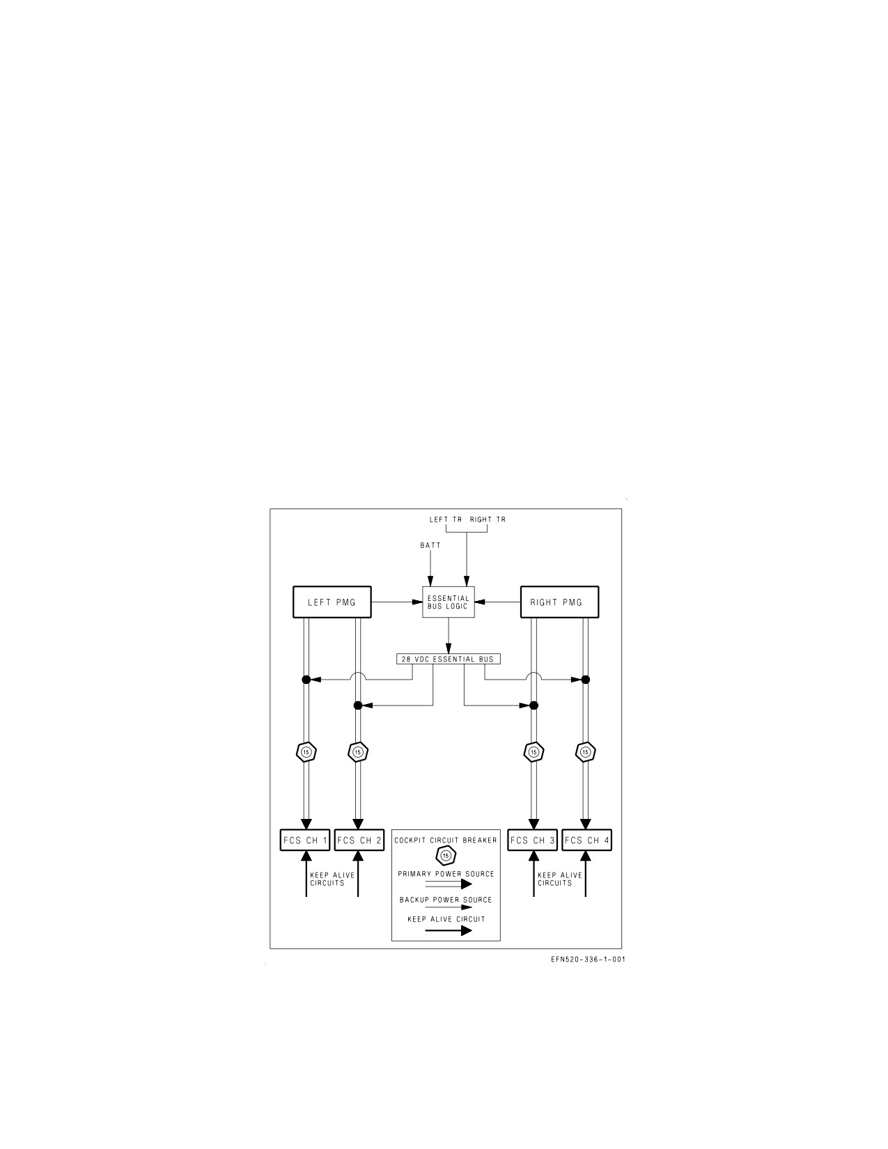
A1-F18EA-NFM-000
determine whether an EBB PMG or the battery is powering the essential bus following a dual GEN
failure. These cautions are set in only two circumstances.
1. The BATT switch is ON on the ground in the absence of ac power (e.g., first engine start). The
battery is depleting and the switch should be placed to OFF unless APU start is about to be made.
2. The BATT switch is OFF inflight and should be placed to ON to provide essential bus backup
capability from the PMGs and the battery.
2.5.4 External Electrical Power. External electrical power may be connected to the aircraft bus
system through an external power receptacle located on the left forward fuselage. If external power is
not of the proper quality, the external power monitor prevents application of power to the aircraft.
Actuation of 1 to 4 ground power switches is required to energize certain aircraft systems following
application of external power.
The aircraft buses are energized by external power in the same manner as if a generator were
operating provided the BATT switch is OFF or the PARKING BRAKE is set.
2.5.4.1
External Power Switch. The external power switch, located on the ground power panel on the
left console, is spring loaded to the NORM position (figure 2-12).
Figure 2-11. FCC Electrical Redundancy
I-2-34
ORIGINAL
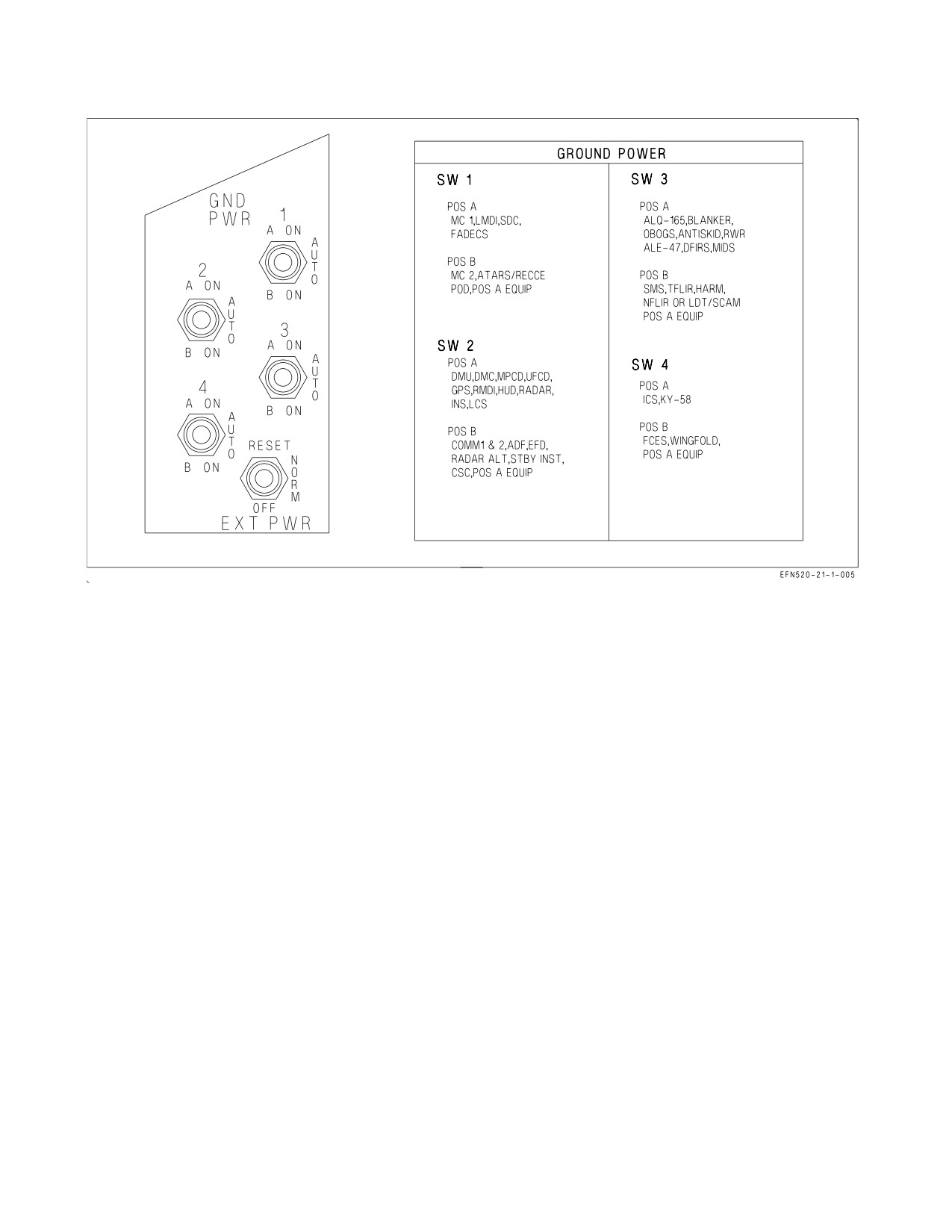
A1-F18EA-NFM-000
Figure 2-12. Ground Power Panel and Placard
RESET
Momentary actuation allows external power to be applied.
NORM
Aircraft buses are energized by external power, provided the switch was first posi-
tioned to RESET. The switch returns to OFF when external power is disconnected.
OFF
Disconnects external power from the aircraft.
2.5.4.2
Ground Power Switches. The four ground power switches are located on the ground power
panel on the left console (figure 2-12). Each switch controls a group of systems and/or instruments, as
listed on a placard above the panel.
A ON
Only systems/instruments listed for the A position are energized by external
power.
AUTO
All controlled systems/instruments are deenergized with external power on the air-
craft. When a generator comes online, the switch(es) automatically revert to
AUTO.
B ON
All controlled systems/instruments (both A and B) are energized by external
power.
The first ground power switch placed to ON must be held for 3 seconds to complete an avionics
overheat BIT. If an avionics overheat condition is present, the switch(es) revert to AUTO and cannot
be returned to ON until the condition is corrected.
I-2-35
ORIGINAL
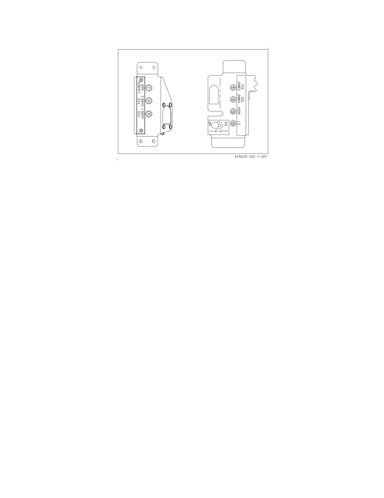
A1-F18EA-NFM-000
Figure 2-13. Circuit Breaker Panels
2.5.5 Circuit Breakers. The circuit breaker panels (figure 2-13), located under each side of the
canopy sill outboard of the left and right consoles, contain the following circuit breakers:
Left Side
Right Side
LAUNCH BAR
FCS CHAN 3
FCS CHAN 2
FCS CHAN 4
FCS CHAN 1
HOOK
LG
2.5.6 Electrical System Cautions and Caution Lights. The following electrical system cautions and
caution lights are described in the Warning/Caution/Advisory Displays in Part V:
• L or R GEN caution and caution light
• BATT SW caution and caution light
• GEN TIE caution light
• L or R DC FAIL caution
2.6
LIGHTING
2.6.1 Exterior Lighting. Exterior lighting is utilized to highlight aircraft position and aspect to other
aircraft, to provide AOA indications to a landing signal officer (LSO), to light the aircraft path for
in-flight refueling, landing or taxi, and to distinguish the F/A-18E/F from other F/A-18 models. The
following exterior lights are provided: strobe lights, position lights, formation lights, approach lights,
refueling probe light, and landing/taxi light (figure 2-14).
Strobe lights and formation lights have two operating modes, normal and NVIS.
2.6.1.1
Exterior Lights Master Switch. The exterior lights master switch, located on the outboard
side of the left throttle grip, provides master control of all exterior lighting except the approach and
landing/taxi lights.
I-2-36
ORIGINAL
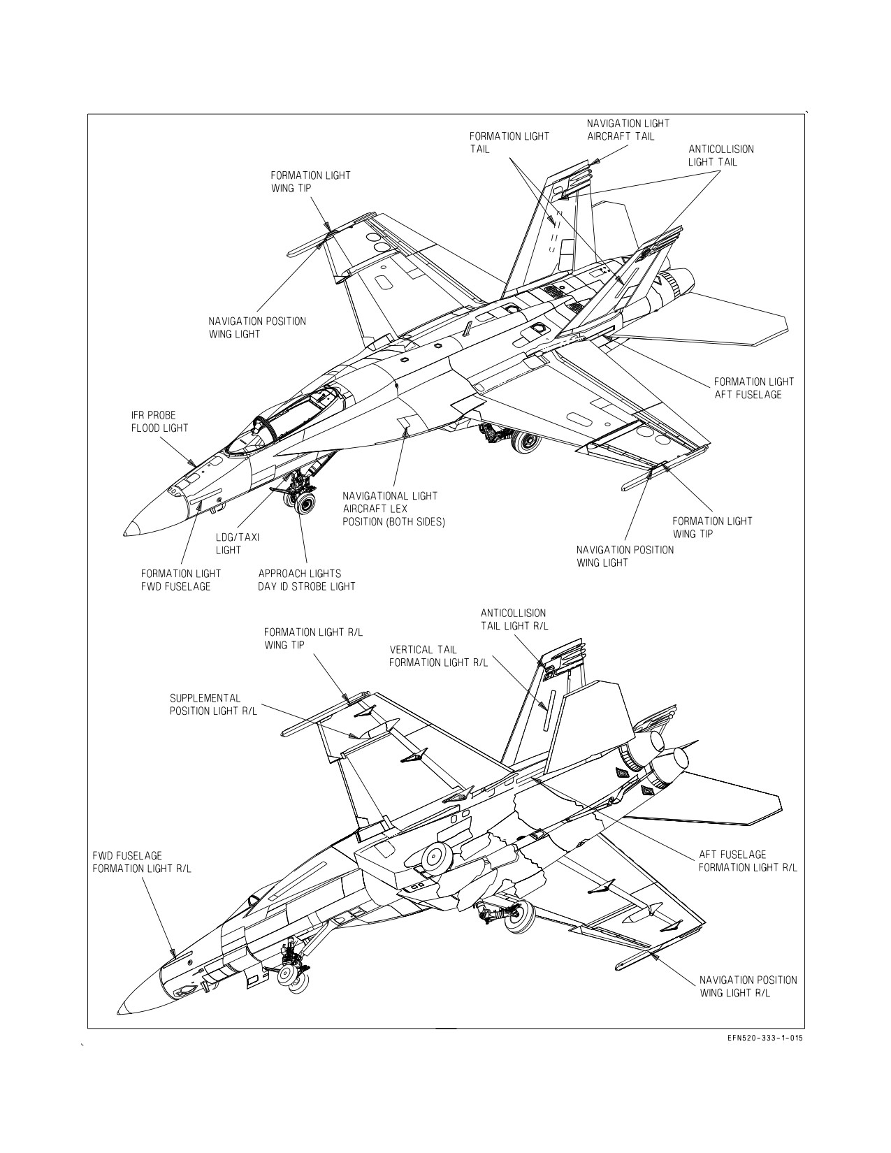
A1-F18EA-NFM-000
Figure 2-14. Exterior Lights
I-2-37
ORIGINAL
A1-F18EA-NFM-000
NORM
Power is available for controlled lighting (strobe and formation lights in normal
(Forward)
mode)
NVIS
Power is available only to the strobe and formation lights in NVIS mode
(Center)
OFF
Power is removed from all controlled lighting. Required position for Day ID light
(Aft)
strobe power ON.
2.6.1.2
Pattern Strobe Lights. Two red anti-collision strobe lights, one on each outboard vertical tail,
are provided to highlight aircraft position during both day and night operations. Each strobe light
contains two bulbs, one normal and one infrared (IR). The external lights master switch determines
which pair of bulbs are powered by the STROBE switch.
2.6.1.2.1
STROBE Switch. The STROBE switch, located on the EXT LT panel on the left console,
is used to apply power and control the brightness of the strobe lights.
BRT Strobe lights on at full intensity (normal or NVIS mode)
OFF Strobe lights off
DIM Strobe lights on at reduced intensity (normal or NVIS mode)
2.6.1.2.2
IDENT Knob. Pattern selection is controlled by the IDENT knob on the exterior lights
panel. The IDENT knob can be set to select strobe patterns of NORM, or A thru F. For night carrier
landings the IDENT knob should be in the NORM position. Refer to figure 2-15 for possible strobe
patterns. Possible strobe patterns are as follows:
NORM Strobe light flashes three times, pauses for 2.44 seconds, then repeats pattern
A
Strobe light flashes two times, pauses 1.92 seconds, then repeats pattern
B
Strobe light flashes once, pauses 0.64 seconds, flashes two times, pauses 2.56 seconds,
then repeats pattern
C
Strobe light flashes two times, pauses 0.64 seconds, flashes once, pauses 2.56 seconds,
then repeats pattern
D
Strobe light flashes three times, pauses 2.88 seconds, flashes once, pauses 0.64 seconds,
then repeats pattern
E
Strobe light flashes three times, pauses 0.64 seconds, flashes two times, pauses 3.2 sec-
onds, then repeats pattern
F
Strobe light flashes two times, pauses 0.64 seconds, flashes two times, pauses 2.88 sec-
onds, then repeats pattern
2.6.1.3
Position Lights. The position lights are provided to highlight the aircraft aspect during night
or reduced visibility operation. There are seven position lights, three red, three green, and one white.
The white position light is on the tail. Three red position lights are installed on the left side. One on
I-2-38
ORIGINAL
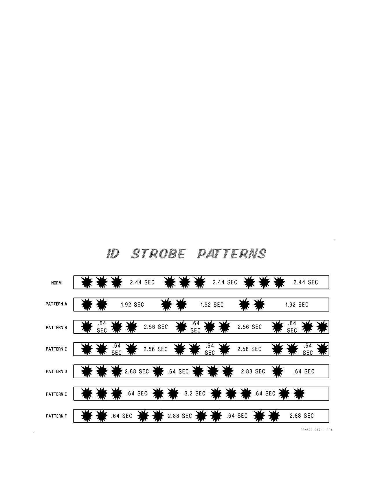
A1-F18EA-NFM-000
the wingtip, one on the LEX just forward of the wing root and one under the wing at the aileron hinge.
Green position lights are installed at the same locations on the right side.
2.6.1.3.1
POSITION Lights Knob. The POSITION lights knob, located on the EXT LT panel on the
left console, is used to apply power and control the brightness of the position lights (external lights
master switch NORM). The knob provides variable lighting intensity between the OFF and BRT
positions.
2.6.1.4
Formation Lights. Ten formation ″strip″ lights, five on each side of the aircraft, are provided
to highlight the aircraft aspect during night or low visibility formation flight. Strip lights are located
on the forward fuselage forward of the LEX, on the wingtip above the missile rail, on the wingtip below
the missile rail, on the aft fuselage below the vertical tail, and on the vertical tail. Each formation light
contains two lighting strips, one normal and one IR. The external lights master switch determines
which set of strips are powered by the FORMATION lights knob.
2.6.1.4.1
FORMATION Lights Knob. The FORMATION lights knob, located on the EXT LT panel
on the left console, is used to apply power and control the brightness of the formation strip lights. The
knob provides variable lighting intensity between the OFF and BRT positions in either the normal or
NVIS mode.
2.6.1.5
Approach Lights. The approach lights, located on the nose gear strut, provide AOA
indications to an LSO during carrier landings. Three approach lights are provided to indicate a fast
(red), on-speed (amber), or slow (green) AOA condition. The approach lights are powered with WoffW
and all landing gear down and locked. Therefore, the approach lights are an external indication that the
Figure 2-15. ID Strobe Patterns
I-2-39
ORIGINAL
A1-F18EA-NFM-000
landing gear are down and locked. The approach lights flash when the HOOK BYPASS switch is in the
CARRIER position and the arresting hook is not down, indicating to an LSO that the hook must be
lowered for a carrier arrestment. The approach lights are dimmed by the WARN/CAUT lights knob.
2.6.1.6
HOOK BYPASS Switch. The HOOK BYPASS switch, located on the lower left main
instrument panel, is spring loaded to the CARRIER position and is electrically held in the FIELD
position.
FIELD
Approach lights and AOA indexers do not flash regardless of hook position. The
switch reverts to the CARRIER position if the hook is lowered.
CARRIER Approach lights and AOA indexers flash if the hook is not down
2.6.1.7
Landing/Taxi Light. A landing/taxi light, located on the nose gear strut, is used to light the
flightpath during landing or a taxiway/runway during ground operations.
2.6.1.7.1
LDG/TAXI Light Switch. The LDG/TAXI light switch is located on the lower left main
instrument panel.
ON Landing/taxi light on with the LDG GEAR handle DN and the nose gear down and
locked
OFF Landing/taxi light off
2.6.1.8
Day ID Light. A high intensity white strobe light is mounted below the approach light on the
nose gear strut. The strobe light operates with the landing gear down and locked, WoffW, and the
exterior lights master switch in the OFF (aft) position.
2.6.1.8.1
Day ID Test Switch. A day ID test switch, located in the nose wheel on frame 233, is
provided to test the day ID strobe light. The switch operates only with ac power applied to the aircraft.
TEST The day ID strobe light comes on, ID LT is displayed on the LDDI, and the master
caution light and aural tone come on.
OFF The switch is spring loaded to the OFF position.
2.6.2 Interior Lighting. Interior lighting is utilized to provide adjustable cockpit lighting for the main
instrument panel and consoles during night or low light operations. All controls for interior lighting are
located on the INTR LT panel on the right console, except for the utility flood light, the AOA indexers,
and the five cockpit displays.
2.6.2.1
MODE Switch. The MODE switch, located on the INTR LT panel, is used to select one of
three cockpit lighting modes; allowing the pilot to optimize interior lighting for current ambient light
conditions.
I-2-40
ORIGINAL
A1-F18EA-NFM-000
NVG Reduces the brightness range for the warning, caution, and advisory lights, the UFCD,
MPCD, EFD, (LOT 25 AND UP) AMPD, and (LOT 26 AND UP) 8 x 10 display. This
disables the integral console lights and the white floodlights; and enables six NVG com-
patible floodlights to illuminate the consoles.
NITE Reduces the brightness range for the warning, caution, and advisory lights, the UFCD,
MPCD, EFD, (LOT 25 AND UP) AMPD, and (LOT 26 AND UP) 8 x 10 display.
DAY Provides the maximum brightness range for all interior lighting.
The UFCDs, MPCD, EFD, (LOT 25 AND UP) AMPD, and (LOT 26 AND UP) 8 x 10 display reset
to DAY mode brightness after aircraft shutdown. Following electrical power interruption, these
displays reset to DAY mode brightness with the mode switch in DAY or NITE positions, and to NITE
mode brightness with the mode switch in NVG position.
2.6.2.2
CONSOLES Lighting Knob. The CONSOLES lighting knob, located on the INTR LT panel,
is used to control the brightness of the integral lighting for the left and right consoles, the hydraulic
pressure gauge, and both circuit breaker panels. Clockwise rotation of the knob increases console
lighting intensity from the OFF to BRT positions. The CONSOLES knob and integral console lighting
are disabled in the NVG mode.
2.6.2.3
INST PNL Lighting Knob. The INST PNL lighting knob, located on the INTR LT panel, is
used to control the brightness of the integral lighting for the main instrument panel and the standby
magnetic compass. Clockwise rotation of the knob increases main instrument panel lighting intensity
from the OFF to BRT positions. The strobe function of the SHOOT light is disabled when the
instrument lights are on.
2.6.2.4
FLOOD Lights Knob. The FLOOD knob, located on the INTR LT panel, is used to control the
brightness of the white cockpit floodlights. Eight floodlights are provided for secondary lighting; three
above each console and one on either side of the main instrument panel. Clockwise rotation of the knob
increases floodlight intensity from the OFF to BRT positions. The FLOOD knob and all white
floodlights are disabled in the NVG mode. There is no brightness control for the six NVG floodlights.
2.6.2.5
CHART Light Knob. The CHART light knob, located on the INTR LT panel, is used to
control the brightness of the NVG compatible chart light. The chart light is located on the canopy bow
at the 10:30 position and rotates in two axes. Clockwise rotation of the knob increases chart light
intensity from the OFF to BRT positions.
2.6.2.6
Utility Floodlight. The utility floodlight, normally stowed above the right console, provides a
portable source of secondary lighting. An attached alligator clip allows the light to be fastened at
various locations in the cockpit. The light contains a knob which provides variable lighting intensity
from off to bright and a button which, when pressed, illuminates the light at full intensity. The light
also contains a rotary selector for white or NVG compatible green lighting.
2.6.2.7
Emergency Instrument Lights. The emergency instrument lights, located on the left and
right sides of the main instrument panel, illuminate the EFD and standby flight instruments in the
absence of ac electrical power. The lights come on anytime the PMGs or the battery are powering the
essential bus. There is no separate cockpit control for the emergency instrument lights.
I-2-41
ORIGINAL
A1-F18EA-NFM-000
2.6.2.8
Engine Instrument Light. The engine instrument light, located on the left side of the main
instrument panel, provides lighting for the EFD during battery start of the first engine. The light
comes on when the APU switch is placed to ON.
2.6.2.9
WARN/CAUT Lights Knob. The WARN/CAUT knob, located on the INTR LT panel, is used
to control the brightness of the warning, caution, and advisory lights in the reduced brightness range.
Clockwise rotation of the knob increases warning, caution, and advisory light intensity from the OFF
to BRT positions. The brightness is maximum in the DAY mode and in the reduced brightness range
in the NITE and NVG modes.
Following a power interruption in either the DAY or NITE mode, the warning, caution, and advisory
lights default to the maximum brightness range. Following a power interruption in the NVG mode, the
warning, caution, and advisory lights remain in the reduced brightness range.
2.6.2.10 LT TEST Switch. The LT TEST switch, located on the INTR LT panel, is spring loaded to
the OFF position. The switch is used to test important cockpit lighting to verify bulb integrity prior to
flight. The switch requires ac electrical power to operate.
TEST Powers all operating warning, caution, and advisory lights, the AOA indexer lights, the
integral backg1round lighting on the EFD (BINGO, MODE, and BRT), changes MENU
to ENG on the DDIs, provides a CHECK SEAT caution in the F/A-18E, and annunci-
ates the landing gear warning tone.
OFF Lights test off
2.6.3 Interior Lighting (F/A-18F). All controls for the interior lights of the rear cockpit are located
on the INTR LT panel on the right console. The controls operate in the same manner as those in the
front cockpit with two exceptions. There is no MODE switch on the rear cockpit INTR LT panel, and
the rear cockpit LT TEST switch does not illuminate the AOA indexer lights or annunciate the landing
gear warning tone.
2.7 HYDRAULIC POWER SUPPLY SYSTEM
The hydraulic power supply system is a dual pressure system (3,000 and 5,000 psi). The aircraft uses
hydraulic power to actuate primary flight control surfaces and to run the following utility hydraulic
functions: landing gear, wheel brakes and anti-skid, hook, launch bar, refueling probe, nosewheel
steering (NWS), gun, and parking brake. Two hydraulic accumulators provide emergency hydraulic
power for critical utility functions.
2.7.1 Hydraulic System. The hydraulic power supply system incorporates two independent hydrau-
lic systems, HYD 1 and HYD 2 (figure 2-16). Each system is divided into two branches providing four
independent hydraulic circuits identified as 1A and 1B for the left system and 2A and 2B for the right
system. HYD 1 circuits are dedicated solely to flight controls. HYD 2A powers both flight controls and
most utility hydraulic functions. HYD 2B powers the flight controls and arresting hook and pressurizes
both the APU and emergency brake accumulators.
All flight control surface actuators are powered by one HYD 1 circuit and one HYD 2 circuit, either
simultaneously or through hydraulic switching valves.
The utility system operates at 3,000 psi only. Two pressure reducers, one on HYD 2A and one on
HYD 2B reduce utility circuit pressure to 3,000 psi when pump output is 5,000 psi.
I-2-42
ORIGINAL
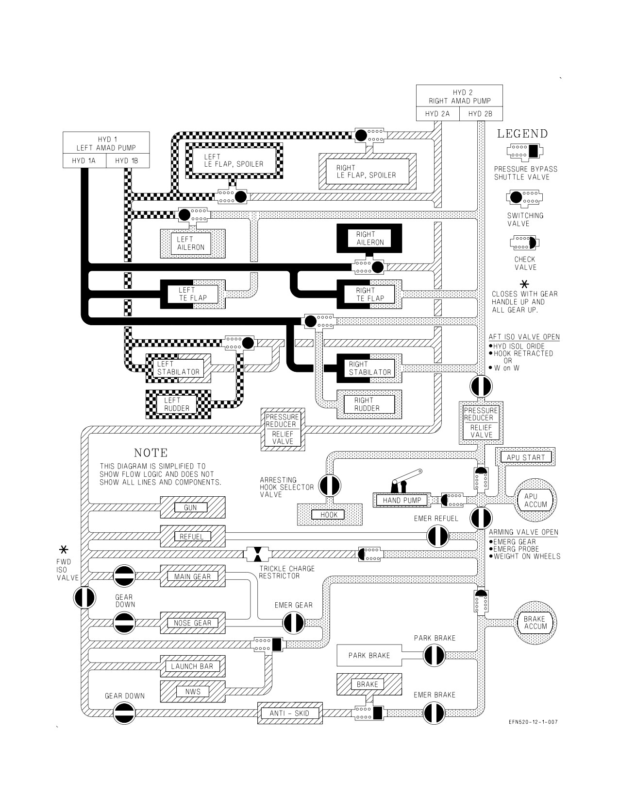
A1-F18EA-NFM-000
Figure 2-16. Hydraulic Flow
I-2-43
ORIGINAL
A1-F18EA-NFM-000
2.7.1.1
Hydraulic Pumps. Each system is pressurized by a single, dual pressure (3,000 and 5,000 psi),
variable displacement pump mounted on an AMAD. Pump output pressure is commanded by the
FCCs based on aircraft flight condition; with 5,000 psi utilized during high-speed flight when air loads
are high. One pump is capable of powering the entire flight control system in the event of a single
system failure. A hydraulic pressure transducer relays system pressure to a hydraulic pressure gauge
in the cockpit. Hydraulic cautions (HYD 1A, HYD 1B, HYD 2A, HYD 2B) are set when individual
hydraulic pressure switches detect circuit pressure below 1,400 psi.
2.7.1.1.1
Hydraulic Pressure Gauge. The hydraulic pressure gauge is located on the lower right main
instrument panel. The gauge has individual needles for indicating HYD 1 and HYD 2 system pressure.
Tick marks for 3,000 and 5,000 psi are provided. Two white bands indicate the range of acceptable
operation pressure (2,600 to 3,300 psi and 4,500 to 5,400 psi). Since the gauge is ac powered, actual
hydraulic readings are not provided until the first generator is online following engine start. During
shutdown, pressure readings freeze when the last generator drops offline.
2.7.1.2
Hydraulic Reservoirs. Hydraulic fluid is supplied to each system by a separate hydraulic
reservoir. The HYD 2 reservoir is larger than the HYD 1 reservoir in order to accommodate the utility
system.
2.7.1.2.1
Reservoir Level Sensing (RLS) System. Each reservoir incorporates an RLS system,
designed to isolate a leak in either system circuit. When reservoir fluid level drops to approximately
50%, RLS shuts off circuit A (HYD 1A or HYD 2A caution). If fluid level continues to deplete to
approximately 30%, RLS restores circuit A and shuts off circuit B (HYD 1B or HYD 2B caution). If
alternate circuit shutdown fails to isolate the leak, RLS restores circuit B (no cautions) at approxi-
mately 15%, providing hydraulic pressure to both systems until fluid depletion (both cautions).
2.7.1.3
Switching Valves. Hydraulic switching valves are utilized to provide backup hydraulic power
to actuators that are not powered simultaneously by both systems. Two hydraulic circuits, a primary
and a backup, provide power to each switching valve.
2.7.1.3.1
Switching Valve Operation. Following a drop in primary circuit pressure (less than 900
(±100 psi)), the switching valve automatically shuts off the primary circuit and tests downstream
pressure to make sure its actuator(s) was not the leakage source which caused the primary circuit loss.
Concurrently, FCC monitoring detects the pressure loss and inhibits FCC actuator failure detection
logic for 10 seconds to allow the switching valve time to function.
If the actuator(s) passes this leak detection test, the switching valve allows the backup circuit to
provide hydraulic power. If the actuator(s) fails the test, the switching valve isolates both circuits to
prevent additional loss of the backup circuit. At the expiration of the 10 second timer, the FCCs no
longer inhibit actuator failure detection logic. With both circuits isolated, this logic Xs LEF actuators
immediately and rudder or aileron actuators only when the actuator is subsequently commanded to
move. It is for this reason that the FLAP switch is cycled during the post-flight switching valve check.
Switching valve operation is completely hydro-mechanical, separate from electrical inputs or FCS
reset commands. As mechanized, there is no hazard associated with multiple reset attempts to regain
an Xd surface following a hydraulic circuit failure.
Preference is given to the primary circuit at all times. The switching valve transfers to the primary
circuit any time primary circuit pressure recovers above 2,000 psi, regardless of the valve position or the
backup circuit pressure level.
I-2-44
ORIGINAL
A1-F18EA-NFM-000
NOTE
If the leak detection test failed due to cavitation in the actuator, the
switching valve resets, runs another test, and completes the switch to
the backup circuit. This self-resetting feature may require several
minutes to complete depending on surface loading, hydraulic system
pressure, and system temperature. In this case, an FCS reset restores
an X’d surface if and when the switching valve successfully transfers to
the backup circuit.
2.7.1.4
Hydraulic Isolation Valves. HYD 2 utility functions that are required only during takeoff,
landing, and ground operations are downstream of isolation valves. The forward isolation valve is
closed when the LDG GEAR handle is UP and all three landing gear are up and locked; isolating the
nose gear, NWS, launch bar, wheel brakes, and anti-skid. The aft isolation valve and the arming valve
are open with WonW and are normally closed inflight; isolating arresting hook retraction, parking
brakes, and emergency brakes. The aft isolation valve is manually opened inflight by hook retraction
or by holding the HYD ISOL switch in ORIDE. The arming valve is manually opened inflight by
emergency gear or emergency probe extension.
2.7.2 Hydraulic Accumulators. Two hydraulic accumulators are provided in the HYD 2B circuit; the
auxiliary power unit (APU) accumulator and the brake accumulator.
The APU accumulator provides hydraulic pressure to start the APU. With a HYD 2 failure, pressure
from the APU accumulator can be used to:
a. Emergency extend the landing gear or refueling probe inflight.
b. Provide emergency nosewheel steering on the ground.
c. Aid the brake accumulator with emergency braking.
On the ground with engines shutdown, the brake accumulator provides hydraulic pressure to set the
parking brake. With a HYD 2 failure, pressure from the brake accumulator can be used to provide
emergency braking. A fully charged brake accumulator provides a minimum of ten full brake
applications.
The APU and brake accumulator charges are maintained against normal leakage and temperature
fluctuations by a trickle-charge restrictor connected to HYD 2A. Additionally, both accumulators may
be manually recharged inflight using HYD 2B pressure by placing the HYD ISOL switch to ORIDE.
This procedure recharges the brake accumulator if and only if the arming valve is open (emergency gear
or emergency probe extension previously selected). Both accumulators can be charged on the ground
by a hand pump located in the right main landing gear wheelwell.
2.7.2.1
Brake Accumulator Pressure Gauge. The brake accumulator pressure gauge is located on
the lower left main instrument panel and is redlined to indicate pressure below 2,000 psi. The BRK
ACCUM caution is displayed when brake accumulator pressure drops below 2,000 psi. The caution and
redlined pressure indication are warnings that approximately five full brake applications remain before
the brake accumulator is empty. When ac power is not applied, power to the gauge is controlled by the
BRK PRESS switch.
2.7.2.1.1
BRK PRESS Switch. The BRK PRESS switch, located on the forward left console, is spring
loaded to the aft position.
I-2-45
ORIGINAL
A1-F18EA-NFM-000
Forward
Applies maintenance bus power to the brake accumulator pressure gauge when ac
(unmarked)
power is not applied.
Aft
Brake accumulator pressure gauge unpowered when ac power is not applied.
(unmarked)
2.7.2.2
HYD ISOL Switch. The HYD ISOL switch, located on the aft left console, is spring loaded to
the NORM position.
ORIDE
Opens the aft isolation valve in flight allowing HYD 2B pressure to recharge the
brake and/or APU accumulators. Following emergency landing gear extension, the
switch may need to be held for up to 20 seconds to remove the APU ACCUM cau-
tion and provide a full charge (up to 40 seconds following an in-flight APU start).
NORM
Allows normal aft isolation valve functioning.
If an APU ACCUM caution appears in flight and is not related to
emergency gear/probe extension or APU start, it may indicate a possible
leak in the isolated HYD 2B system. A BRK ACCUM caution in flight is
not normal and may indicate a possible leak in the isolated HYD 2B
system.
2.7.3 Hydraulic System Related Cautions and Caution Light. The following hydraulic system
related cautions and caution light are described in the Warning/Caution/Advisory Displays in Part V:
D HYD 1A, HYD 1B, HYD 2A, HYD 2B
D BRK ACCUM
D HYD 5000
D APU ACCUM caution and caution light
D HYD 1 HOT, HYD 2 HOT
2.8 UTILITY HYDRAULIC FUNCTIONS
The utility hydraulic functions are powered by HYD 2 and include landing gear extension and
retraction, nosewheel steering, wheel braking and anti-skid, launch bar extension, arresting hook
retraction, and in-flight refueling probe extension and retraction. Operation of the in-flight refueling
probe is described in the Fuel System section.
2.8.1 Landing Gear System. The landing gear is a tricycle design and includes a nose landing gear
with steerable nosewheel and two fixed main landing gear. The nose landing gear retracts forward,
while the main landing gear retract aft and inwards. When the landing gear is extended, all landing gear
doors remain open.
2.8.1.1
Planing Links. Each main landing gear assembly incorporates a planing link, which is
designed to properly align the main wheels after landing gear extension. The joint which connects the
wheel to the main landing gear lever is designed to rotate off-axis, so that the wheel fits properly into
the main landing gear wheelwell. The planing link rotates the main wheel from its stowed orientation,
aligns it with the longitudinal axis of the aircraft, and locks over-center. A planing link proximity
switch is used to verify proper planing link position and thereby proper wheel alignment. A flashing
main landing gear position light is used to provide an indication of a planing link failure.
I-2-46
ORIGINAL