F18. FLIGHT MANUAL (2008) - page 18
A1-F18EA-NFM-000
2.8.1.2
Normal Landing Gear Extension and Retraction. Normal landing gear extension and
retraction is electrically controlled by the LDG GEAR handle and uses hydraulic pressure from HYD
2A. With weight off the nose gear and the launch bar retracted, moving the LDG GEAR handle to the
UP position sends an electrical signal to the landing gear selector valves to initiate normal landing gear
retraction. Likewise, moving the LDG GEAR handle to the DN position sends an electrical signal to the
landing gear selector valves to initiate normal landing gear extension
If the launch bar does not return to the up and locked position after catapult launch or the nose gear
indicates WonW, the nose landing gear cannot be retracted. In either case, placing the LDG GEAR
handle UP will raise the main landing gear and leave the nose landing gear extended.
2.8.1.3
Emergency Landing Gear Extension. Emergency landing gear extension is mechanically
controlled by the LDG GEAR handle (front cockpit) or the EMERG LDG GEAR handle (rear cockpit
Lots 21 thru 25) and uses hydraulic pressure provided by the APU accumulator. Both handles are
mechanically connected to the landing gear emergency selector valves by a series of levers and cables.
Emergency extension is mechanically activated by rotating the LDG GEAR handle 90° clockwise and
pulling to detent (approximately 1.5 inches) or by pulling the EMERG LDG GEAR handle to the
detent.
Emergency landing gear extension opens the hydraulic arming valve and directs APU accumulator
pressure to the emergency selector valves. APU accumulator pressure is used to unlock the doors,
release the landing gear uplocks, and is applied to the drag brace locking actuator and sidebrace
downlock actuator. The nose landing gear extends by freefall aided by airloads and the drag brace
locking actuator. The main landing gear extends by freefall aided by the sidebrace downlock actuator.
Emergency extension can be performed with the LDG GEAR handle either UP or DN (DN is
recommended).
2.8.1.4
LDG GEAR Handle. The wheel-shaped LDG GEAR handle, located on the lower left main
instrument panel in the front cockpit, is used to control landing gear extension and retraction. A
downlock solenoid in the LDG GEAR handle assembly prevents gear retraction with WonW by
preventing movement of the handle from the DN position.
UP
With WoffW and the launch bar retracted, electrically initiates normal
landing gear retraction.
DN
Electrically initiates normal landing gear extension.
Emergency
Mechanically initiates emergency landing gear extension.
(Rotate handle 90°
clockwise and pull
to the detent)
2.8.1.5
DOWNLOCK ORIDE Button. The DOWNLOCK ORIDE button, located on the lower left
main instrument panel outboard of the LDG GEAR handle, is used to override the downlock solenoid.
If the downlock solenoid does not retract with WoffW (LDG GEAR handle cannot be moved from the
DN position), a failure has occurred in the downlock circuitry (Landing Gear Control Unit). If the
landing gear indicate three down and locked, cycling the landing gear handle is not recommended, as
proper landing gear functioning is questionable. However, if dictated by an emergency situation,
pressing and holding the DOWNLOCK ORIDE button will retract the mechanical stop and allow the
LDG GEAR handle to be moved to the UP position.
I-2-47
ORIGINAL
A1-F18EA-NFM-000
The LDG GEAR handle must be in the full down position for the mechanical stop to properly engage
after landing (WonW).
If the DOWNLOCK ORIDE button is pressed or the mechanical stop is
not fully engaged, the LDG GEAR handle can be raised on the ground,
and the main landing gear will retract. The nose gear will not retract with
weight on the nose gear.
2.8.1.6
EMERG LDG GEAR Handle (F/A-18F). The EMERG LDG GEAR handle is located on the
lower left main instrument panel in the rear cockpit. Pulling the handle to the detent mechanically
initiates emergency landing gear extension.
2.8.1.7
Landing Gear Control Unit (LGCU). The LGCU monitors the position of the landing gear and
launch bar systems, provides cockpit indications of gear/launch bar position, and provides outputs to
various aircraft systems which are dependent on gear position (e.g., FCC A and B, the SMS, and the
SDC). The LGCU does not control landing gear extension and retraction.
The LGCU receives inputs from the LDG GEAR handle, the LAUNCH BAR switch, and the
following proximity switches: launch bar, landing gear uplocks, landing gear downlocks, planing links,
and WonW. The LGCU controls the red and green L BAR warning/advisory lights, the landing gear
position lights, the light in the gear handle, the landing gear warning tone, the downlock solenoid, and
all inputs to the FCCs and the SMS. The LGCU also performs a self-BIT and a functional check of all
proximity switches, providing MSP code input to the SDC.
2.8.1.8
Landing Gear Warning Light and Warning Tone. The landing gear warning light is a red light
located inside the LDG GEAR handle. The landing gear warning tone is a beeping tone heard in the
headset. The landing gear warning light and warning tone serve three purposes: to indicate a mismatch
between LDG GEAR handle position and actual gear position, to warn of a planing link failure, and to
provide a ″wheels warning.″
A steady warning light comes on whenever the landing gear is in transit and remains on until all
three gear are down and locked (LDG GEAR handle DN) or all gear doors are closed and locked (LDG
GEAR handle UP). If the landing gear is unsafe, the landing gear warning light remains on. The
warning tone is inhibited for 15 seconds to allow for normal landing gear extension and retraction. If
the warning light remains on for 15 seconds, the warning tone is annunciated to provide an aural
indication of unsafe landing gear position.
If a left or right planing link failure occurs with the landing gear down and locked (planing link
proximity switch not properly activated), the landing gear warning light will come on immediately
accompanied by the warning tone.
Lastly, when the LDG GEAR handle is UP, a flashing warning light accompanied by the warning
tone will be activated when airspeed is below 175 KCAS, altitude is less than 7,500 feet, and rate of
descent is greater than 250 fpm. This ″wheels warning″ is provided as a cue to check the position of the
landing gear at flight conditions where the LDG GEAR handle should normally be DN. The wheels
warning is also activated if calibrated airspeed and/or barometric altitude data are lost. In this case, the
standby airspeed and/or altitude indicators should be referenced prior to silencing the warning tone.
I-2-48
ORIGINAL
A1-F18EA-NFM-000
2.8.1.8.1
WARN TONE SIL Button. The WARN TONE SIL button, located to the left of the LDG
GEAR handle, is used to silence the landing gear warning tone.
2.8.1.8.2
Landing Gear UNSAFE Light (F/A-18F). The landing gear UNSAFE light is a red light
located on the upper left main instrument panel in the rear cockpit. The light indicates a mismatch
between LDG GEAR handle position and actual gear position (e.g., gear in transit). The light does not
illuminate for a planing link failure, wheels warning, or loss of air data.
2.8.1.9
Landing Gear Position Lights. Three green landing gear position lights, located on the lower
left main instrument panel, are labeled NOSE, LEFT, and RIGHT. When the LDG GEAR handle is
DN, steady lights indicate that the corresponding landing gear is down and locked. The LEFT and
RIGHT landing gear position lights are also used to indicate a planing link failure. If the main landing
gear are down and locked but a planing link proximity switch is not properly activated, the
corresponding position light will flash.
A landing gear position of three down and locked is indicated by three steady green position lights
with the landing gear warning light out. Additionally, when illuminated inflight, the approach lights
provide an external indication that the landing gear is down and locked.
If a landing gear position light is out with the LDG GEAR handle DN and the landing gear warning
light out, a LT TEST should be performed to test the integrity of the position light bulb. If the bulb
tests bad, it is safe to assume that the gear is down and locked. During day operations, if all three
position lights appear to be out/dim, make sure the interior lights MODE switch is in the DAY position.
A landing gear position of three up and locked is indicated by the landing gear warning light out with
all three position lights out.
If one or more landing gear indicates unsafe, a visual inspection can only
confirm general position and obvious damage. There is no external
indication of a locked landing gear.
2.8.1.9.1
Landing Gear Position Lights (F/A-18F). Three green landing gear position lights, labeled
NOSE, LEFT, and RIGHT, are located on the upper left main instrument panel in the rear cockpit.
These lights have the same functionality as those in the front cockpit.
2.8.2 Nosewheel Steering System (NWS). The NWS system is used to provide directional control
and shimmy damping during ground operations. The NWS hydraulic power unit, attached to the nose
landing gear strut, is electrically controlled by commands from the FCCs and is hydraulically actuated
by pressure from HYD 2A (primary) or HYD 2B/ APU accumulator (backup). In the event of a HYD
2A failure, a pressure-biased shuttle valve routes HYD 2B pressure (if available), or APU accumulator
pressure to the NWS unit for backup operation. The FCCs accept input from the rudder pedals to
provide NWS commands.
The NWS system has two modes, NWS (low) and NWS HI. In the low mode (NWS cue in the HUD),
full rudder pedal deflection commands approximately 22.5° of nosewheel deflection. In the high mode
(NWS HI cue in the HUD), full rudder pedal deflection commands approximately 75° of nosewheel
deflection. The NWS system (low gain) incorporates a yaw rate feedback input from the FCCs, which
I-2-49
ORIGINAL
A1-F18EA-NFM-000
is designed to suppress directional PIO tendencies by increasing directional damping during takeoff
and landing roll.
With loss of yaw rate information to the FCCs, directional PIO may occur
during aggressive ground tracking.
If the NWS system fails, the NWS caution is displayed and the NWS or NWS HI cue is removed
from the HUD. When failed, the NWS system reverts to a 360° free-swiveling mode.
2.8.2.1
NWS Engagement/Disengagement. With WonW, manual NWS engagement is provided by
actuation of the NWS/undesignate button. The method required to engage each of the two NWS
modes (low and high) is dependent on wing lock/unlock status.
With the wings spread and locked and NWS disengaged, the first momentary press and release of the
NWS button engages full-time NWS (low). NWS HI is engaged by subsequent press and hold of the
NWS button. With NWS disengaged, press and hold for greater than 1 second also engages NWS HI.
If the NWS button is released, the system reverts to NWS (low).
With the wings unlocked and NWS disengaged, the first momentary press and release of the NWS
button still engages full-time NWS (low). However, subsequent press and release engages full-time
NWS HI, providing hands-free NWS HI capability for operations in the carrier environment. If the
wings are subsequently spread and locked, NWS reverts to the low mode.
During landing, full-time NWS (low) is automatically engaged when the nose landing gear and at
least one main landing gear transition to WonW. If NWS is engaged with both HYD 2A and 2B failures,
the NWS or NWS HI cue will flash in the HUD as an indication that APU accumulator pressure is
depleting.
NWS is manually disengaged by pressing the paddle switch. NWS is automatically disengaged for
catapult launch, when the launch bar is extended. With the launch bar extended, NWS (low) can be
momentarily engaged to position the launch bar by press and hold of the NWS button. Additionally,
NWS is automatically disengaged when the nose landing gear transitions to WoffW during takeoff or
when power is removed from the FCCs.
2.8.2.2
Emergency High Gain NWS. With a FCS CH 2 or FCS CH 4 failure, normal nosewheel
steering is lost. Emergency high gain NWS can be regained by pulling the failed channel circuit
breaker, unlocking the wings, and momentarily pressing the nosewheel steering button.
When emergency high gain NWS mode is entered, NWS indications may
not be displayed on the HUD. As a result, inadvertent nosewheel steering
actuation may injure ground personnel.
2.8.3 Wheel Brake System. The aircraft’s wheel brake system provides normal braking, anti-skid,
emergency braking, a parking brake, and main wheel anti-spin. Normal braking utilizes HYD 2A
pressure and is capable of functioning with a separate anti-skid system. The anti-skid system, when
enabled, provides maximum braking effectiveness on wet runways or during heavy braking by
I-2-50
ORIGINAL
A1-F18EA-NFM-000
preventing wheel skid. When selected, emergency braking utilizes HYD 2B pressure, if available, or
brake and APU accumulator pressure to provide backup braking capability following a HYD 2A
failure. The anti-spin function stops main landing gear wheel rotation prior to landing gear retraction.
2.8.3.1
Wheel Brake Assembly. Each main landing gear wheel is fitted with hydraulically actuated
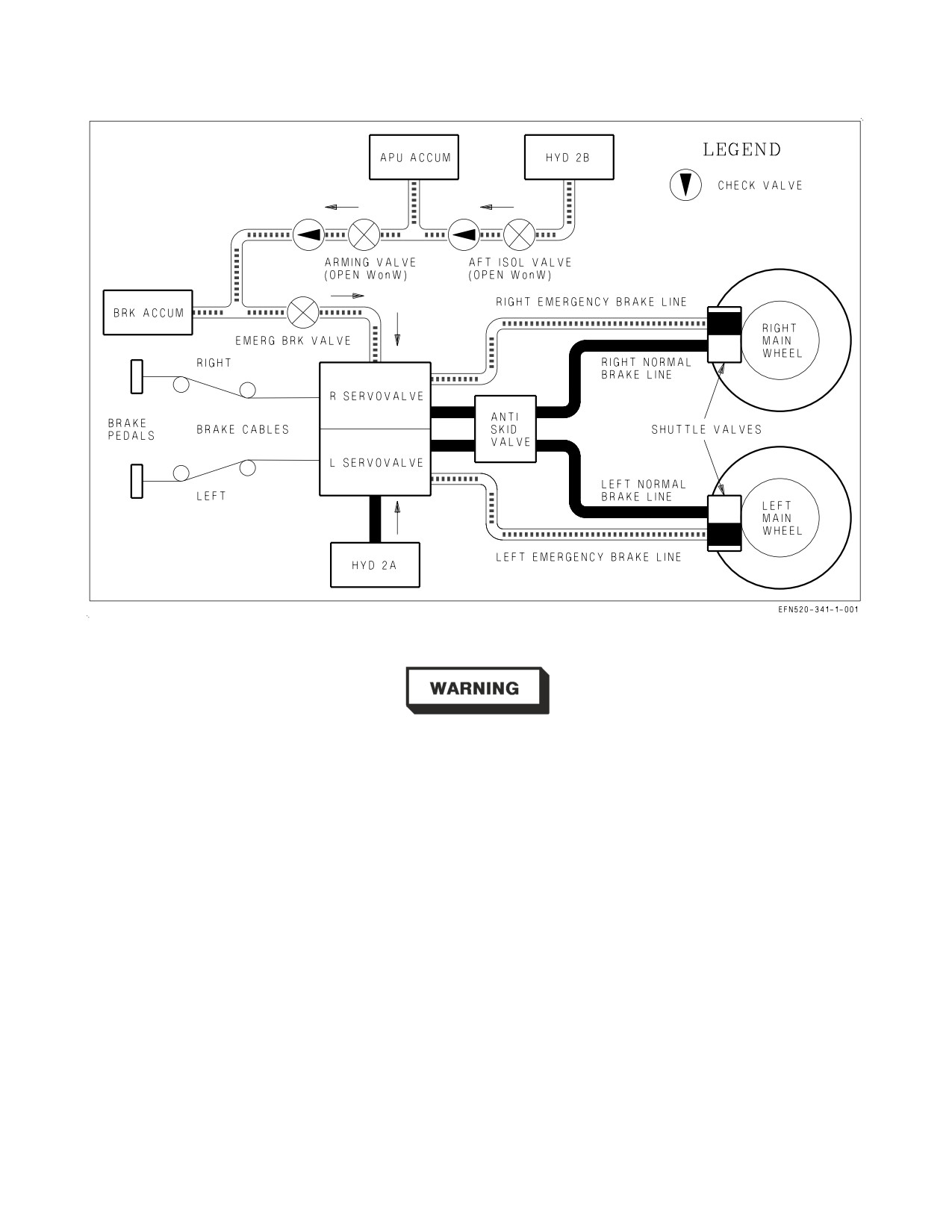
multiple disk brakes. There are two independent sets of brake lines running to each wheel brake
assembly: the normal brake line pressurized by HYD 2A and the emergency brake line pressurized by
HYD 2B or the brake and APU accumulators. See figure 2-17. Only one set of brake lines can be
pressurized at any given time. A shuttle valve on each wheel brake assembly switches from normal to
emergency brake pressure, depending on which is applied.
Each wheel brake assembly has a brake wear indicator pin, located on the inboard side of the wheel.
When the brakes are applied and the indicator pin is flush or below flush with the brake housing, the
brake pads require changing.
Each wheel assembly incorporates a fuse plug which is designed to melt and deflate the tire at
temperatures below those which would result in a catastrophic tire blowout.
2.8.3.2
Wheel Brake Operation. Each main wheel brake is controlled by a separate brake pedal,
integrated into the rudder/brake pedal mechanism. Pilot applied force to the top of each brake pedal
is transmitted by a series of cables and pulleys directly to the brake control hydraulic servovalves,
located in the nose wheelwell. The amount of hydraulic pressure applied to the wheel brakes by the
servovalves is directly proportional to brake pedal force. Dual brake pedal action provides symmetric
braking, while individual brake pedal action provides differential braking. In the F/A-18F (trainer
configuration), a second set of cables are routed to the servovalves from the rear cockpit brake pedals.
The servovalves are controlled by the pilot applying the most brake pedal force.
2.8.3.3
Normal Braking. Normal braking is enabled when HYD 2A is operable and the EMERG
BRK handle(s) are in the stowed position. The emergency brake valve is closed and the emergency
brake lines are unpressurized. During normal braking, HYD 2A pressure is applied through the left and
right servovalves proportional to the amount of pilot applied brake pedal force and is routed to the
main wheel brakes. When the ANTI SKID switch is ON, the anti-skid system modulates pilot applied
brake pressure in order to prevent wheel skid. When the ANTI SKID switch is OFF, the pilot must
regulate brake pedal force to prevent wheel skid.
2.8.3.4
Anti-skid System. The anti-skid system performs 4 basic functions which are designed to
maximize braking effectiveness during landing rollout: touchdown protection, wheel spin-up override,
skid control, and locked wheel protection. The anti-skid system is enabled when the ANTI SKID
switch is ON and the LDG GEAR handle is DN.
I-2-51
ORIGINAL
A1-F18EA-NFM-000
Figure 2-17. Wheel Brake and Anti-skid System
Failure of either wheel speed sensor can lead to an anti−skid failure,
resulting in a complete loss of brakes. Placing the ANTI SKID switch to
the OFF position or pulling the EMERG BRK handle will bypass the
faulty system and restore braking ability. Judicious braking must be
used, as the anti−skid system is not available. Refer to the BRAKE
FAILURE/EMERGENCY BRAKES procedure.
The system contains two wheel speed sensors, an anti-skid control unit, and an anti-skid control
valve. The anti-skid control unit senses wheel speed and operates by electronically limiting the amount
of HYD 2A pressure that is applied to the wheel brakes through the anti-skid control valve and the
normal brake lines. Anti-skid is not available when emergency brakes are selected.
Touchdown protection delays initial brake application on landing by completely dumping brake
pressure until (1) weight is on the right main landing gear and wheel speed is over 50 knots or (2), if
a wet runway delays wheel spin-up, for 3 seconds after landing. This function prevents landing with
locked main wheels (tire blowouts) even if full brake pedal force is applied at touchdown.
Wheel spin-up override is activated at 50 knots wheel speed to allow normal braking if the right
WonW switch fails.
I-2-52
ORIGINAL
A1-F18EA-NFM-000
Skid control is enabled when sensed wheel speed differs from what the anti-skid control unit
determines it should be (e.g., hydroplaning is detected). If the system detects wheel skid, anti-skid
limits the amount of HYD 2A pressure applied to both brakes as required to prevent skidding. If no
skid exists, full pilot-applied brake pressure is routed to the brakes.
If the speed of one wheel drops 40% below the other wheel, locked wheel protection dumps brake
pressure to both wheels until the speed of the slower wheel returns above 40% of the other. Locked
wheel protection is removed below 35 knots, so that full braking performance (including locking a tire)
is available for taxi and turning operations. Below 14 knots, anti-skid is completely disabled. Below 35
knots, judicious braking is required to avoid flat spotting tires.
Anti-skid protection is bypassed when the ANTI SKID switch is OFF. Normally limited by the
anti-skid system, 3,000 psi hydraulic brake pressure is available and regulated only by pilot brake pedal
forces. When using brakes at high speed without anti-skid protection, there is a very small margin
between effective braking and blown tires. Any force greater than approximately 55 to 60 lbs applied
to the pedals (6° to 7° of pedal rotation) will likely result in blown tires with either the ANTI SKID
switch OFF or emergency brakes selected. The use of normal (anti-skid off) brakes at high speed
should be done with extreme caution. If braking without anti-skid is needed at high speeds, initially
apply very light brake pedal pressure and gradually increase as required.
Use of brakes without anti-skid at high speed can result in blown tires
resulting in loss of directional control. If practical, rollout speed should be
as slow as possible before applying brake pedal pressure.
NOTE
Hot brakes and/or melted wheel assembly fuze plugs can be expected
any time maximum effort braking is used at heavy gross weights with
or without anti-skid, e.g., aborted takeoff or heavy weight landing
(above 46,000 lb GW) with high taxi brake usage.
2.8.3.4.1
ANTI SKID Switch. The ANTI SKID switch, located on the lower left main instrument
panel, is used to manually disable the anti-skid system, e.g., for carrier operations or following an
anti-skid failure (ANTISKID caution displayed). The switch is lever-locked in the OFF position.
ON
Anti-skid system enabled for use with normal braking.
OFF
Anti-skid system disabled (SKID advisory displayed when the landing gear is
down).
2.8.3.4.2
Anti-skid BIT and the ANTISKID Caution. The anti-skid control unit performs two types of
BIT: initiated and periodic. IBIT is performed when power is initially applied to the anti-skid system:
(1) when the landing gear is lowered, (2) when the ANTI SKID switch is selected from OFF to ON
inflight, or (3) on the ground with the parking brake set. IBIT performs a complete test of the anti-skid
system 9 seconds after power is applied and runs for 4.5 seconds. With WonW, IBIT is inhibited with
the parking brake released, as wheel motion will cause a false BIT failure and brake pressure would be
dumped if brakes were applied. PBIT only performs a partial anti-skid test and runs whenever power
is applied and IBIT is not running.
I-2-53
ORIGINAL
A1-F18EA-NFM-000
If an anti-skid failure is detected by either BIT, the ANTISKID caution will be displayed at BIT
completion. If an anti-skid failure is detected by PBIT, cycling the ANTI SKID switch will command
an IBIT and a more complete test of the system. When IBIT is running, the ANTISKID caution is
inhibited or is removed if previously displayed. If the ANTISKID caution returns after IBIT, the
ANTI SKID switch must be placed to OFF in order to isolate the failure and make sure that normal
braking (without anti-skid) is available.
For instance, assume the right wheel speed sensor has failed and an ANTISKID caution is displayed.
If the ANTI SKID switch is left ON during landing, touchdown protection circuitry will dump and
never restore brake pressure to both wheels. Normal braking will be lost. In this case, placing the ANTI
SKID switch to OFF will restore normal braking (without anti-skid), or pulling the EMERG BRK
handle will enable emergency braking (bypassing anti-skid).
• Do not cycle the ANTI SKID switch in response to an ANTISKID
caution immediately prior to landing. Cycling the ANTI SKID switch
removes the ANTISKID caution for up to 13.5 seconds as the system
performs IBIT even though the anti-skid system may still be failed
and, if the system is not failed, wheel motion at touchdown may cause
a false BIT failure and a dump of normal brake pressure when brakes
are applied.
• If the ANTI SKID switch is not placed to OFF with an ANTISKID
caution displayed, normal braking capability may be lost completely.
2.8.3.5
Emergency Braking. Emergency braking is enabled when either EMERG BRK handle is
pulled to detent. This action opens the emergency brake valve and applies backup hydraulic pressure
to the hydraulic servovalves. If available, backup pressure from HYD 2B is utilized through the aft
isolation and arming valves, which are open with WonW. If HYD 2 is failed completely, backup
pressure from both the brake and APU accumulators is used. Check valves are incorporated to prevent
the loss of accumulator pressure if HYD 2B is failed. With backup pressure applied, the servovalves
isolate HYD 2A pressure, if still available, so that the normal brake lines are unpressurized.
During emergency braking, backup pressure is applied through the left and right servovalves
proportional to the amount of pilot applied brake pedal force and is routed to the main wheel brakes
through the emergency brake lines. These lines bypass the anti-skid control valve, so the pilot must
regulate brake pedal force to prevent wheel skid.
Hydraulic accumulators and the brake accumulator pressure gauge are discussed in the Hydraulic
Power Supply System section.
I-2-54
ORIGINAL
A1-F18EA-NFM-000
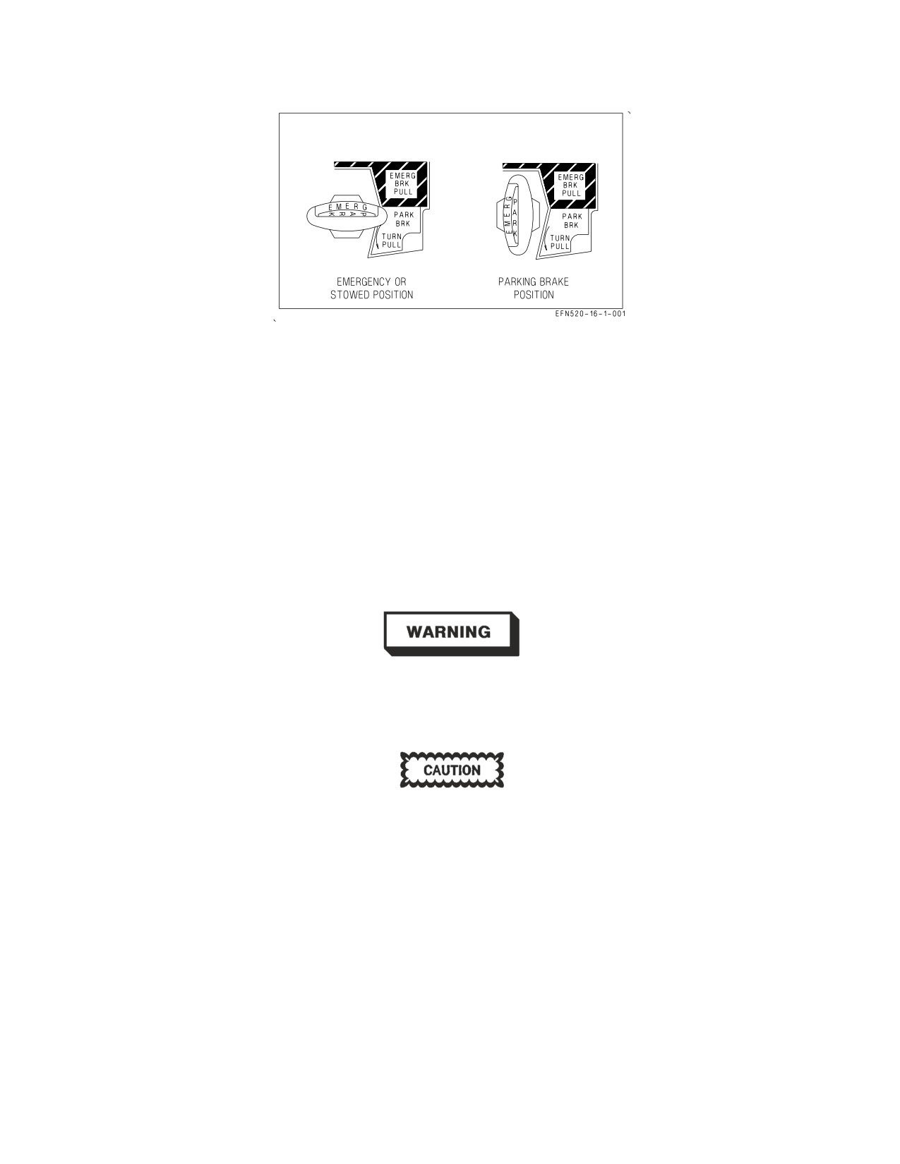
Figure 2-18. Emergency/Parking Brake Handle
2.8.3.5.1
EMERG BRK Handle (Front Cockpit). The EMERG BRK handle is combined with the
PARK BRK handle and is located on the lower left main instrument panel in the front cockpit. When
the handle is in the stowed, emergency position (horizontal), the ‘‘EMERG’’ label appears upright. See
figure 2-18. To select emergency brakes, the handle must be pulled to the detent while in the horizontal
position.
Stowed
Emergency brake valve closed. Normal braking selected.
(unmarked)
PULL
Emergency brake valve open. Emergency braking selected.
(to detent)
The position of the EMERG BRK handle is the only indication that
emergency braking is selected: no warning or caution is displayed. The
EMERG BRK handle(s) must be fully stowed in both cockpits to make
sure that normal braking with anti-skid is available.
Due to friction in the EMERG BRK handle mechanism, the handle may
not return to the fully stowed position unless positively pushed.
2.8.3.5.2
EMERG BRK Handle (Rear Cockpit Lots 21 thru 25). The EMERG BRK handle, located
on the lower left main instrument panel in the rear cockpit, is used to select emergency braking from
the rear cockpit. When stowed, the handle is oriented vertically.
Stowed
Emergency brake valve closed. Normal braking selected.
(unmarked)
PULL
Emergency brake valve open (to detent). Emergency braking selected.
I-2-55
ORIGINAL
A1-F18EA-NFM-000
The position of the EMERG BRK handle is the only indication that
emergency braking is selected: no warning or caution is displayed. The
EMERG BRK handle(s) must be fully stowed in both cockpits to make
sure that normal braking with anti-skid is available.
Due to friction in the EMERG BRK handle mechanism, the handle may
not return to the fully stowed position unless positively pushed.
2.8.3.6
Parking Brake System. The parking brake is used to lock the main landing gear wheels when
the aircraft is parked. The parking brake is activated when the PARK BRK handle is rotated and
pulled to the locked position. This action places the emergency brake valve in the parking brake mode.
Backup hydraulic pressure from HYD 2B or the brake and APU accumulators is applied to the wheel
brake hydraulic servovalves and routed to the main wheel brakes through the emergency brake lines.
The PARK BRK caution will come on to alert the pilot that the parking brake is still set when both
throttles are advanced above about 80% N2 rpm (INS on).
2.8.3.6.1
PARK BRK Handle. The PARK BRK handle is combined with the EMERG BRK handle
and is located on the lower left main instrument panel in the front cockpit. From the stowed
(horizontal) position, the handle must be rotated 90° counterclockwise and pulled to the locked
position, in order to activate the parking brake. When the handle is in the vertical position, the
‘‘PARK’’ label appears upright. See figure 2-18. If emergency brakes are selected, the handle must be
returned to the stowed position before the parking brake can be activated. Rotating the handle 45°
counterclockwise releases the lock and allows the handle to return to the stowed (horizontal) position.
Stowed
Parking brake released. Normal braking selected.
(unmarked)
TURN/
Parking brake set.
PULL
Several aircraft systems utilize parking brake activation to enable or disable logic. A set parking
brake is used to enable anti-skid BIT logic, GEN TIE logic, and INS alignment and is used to trigger
the PARK BRAKE caution.
2.8.3.7
Main Wheel Anti-Spin. The anti-spin function stops main landing gear wheel rotation prior
to landing gear retraction. When the LDG GEAR handle is moved to the UP position, main landing
gear retract pressure is supplied to the anti-skid control valve. Normal brake pressure is blocked and
this anti-spin pressure is routed to the wheel brakes through the normal brake lines. Unlock and
retraction of the main landing gear is delayed until anti-spin pressure is applied and main wheel
rotation has stopped.
2.8.4 Launch Bar System. The launch bar is electrically controlled, hydraulically extended, and
mechanically retracted. With weight on the nose gear, placing the LAUNCH BAR switch to EXTEND
I-2-56
ORIGINAL
A1-F18EA-NFM-000
energizes the launch bar control valve and routes HYD 2A pressure to unlock, lower, and hold down the
launch bar. The green L BAR advisory light indicates that the launch bar has been extended.
With the launch bar extended, returning the LAUNCH BAR switch to RETRACT deenergizes the
launch bar control valve, isolates HYD 2A pressure, and allows dual retract springs to mechanically
return the launch bar to the up and locked position. A launch bar proximity switch is energized when
the launch bar is fully retracted.
When the launch bar is fully extended it is held against the deck by HYD 2A pressure. Deck load
springs allow vertical movement of the launch bar during taxi over the catapult shuttle. When the
aircraft is placed in tension on the catapult, the launch bar is held captive in the extended position by
the shuttle. Once in tension, the LAUNCH BAR switch should be placed to RETRACT in order to
remove HYD 2A pressure from the launch bar. When the LAUNCH BAR switch is placed to
RETRACT, the green L BAR light should go out.
Failure to place the LAUNCH BAR switch to RETRACT prior to
catapult launch may result in launch bar hydraulic seal failure and
possible loss of HYD 2A.
At the end of the catapult stroke, launch bar/shuttle separation occurs and allows the retract springs
to return the launch bar to the up and locked position. When engaged, the launch bar uplock prevents
the launch bar from dropping to the deck due to g-loads during landing.
If the launch bar does not return to the up and locked position after catapult launch (launch bar
proximity switch not energized), the nose landing gear cannot be retracted. In this case, placing the
LDG GEAR handle UP will raise the main landing gear and leave the nose landing gear extended.
2.8.4.1
LAUNCH BAR Switch. The LAUNCH BAR switch, located on the lower left main instrument
panel in the front cockpit, is used to control the position of the aircraft’s launch bar. The switch is
spring loaded to the RETRACT position and is electrically held in the EXTEND position only if
weight is on the nose gear.
RETRACT Launch bar control valve deenergized. Launch bar up.
EXTEND Launch bar control valve energized. Launch bar unlocked and extended by HYD
2A pressure. Green L BAR advisory light on.
2.8.4.2
LB Circuit Breaker. The LB circuit breaker is located on the left-hand circuit breaker panel
above the left console. The LB circuit breaker provides a secondary means to raise the launch bar
following a launch bar malfunction. When pulled, the circuit breaker manually deenergizes the launch
bar control valve, removing HYD 2A pressure and allowing the retract springs to raise the launch bar.
Typically, this action would be required only if (1) the LAUNCH BAR switch failed in the EXTEND
position with weight on the nose gear or (2) the nose gear failed WonW after launch and the pilot failed
to place the LAUNCH BAR switch to RETRACT.
2.8.4.3
L BAR Warning/Advisory Lights. Two L BAR lights, one green and one red, are located on
the left warning, caution, and advisory lights panel. Both lights are controlled by the landing gear
I-2-57
ORIGINAL
A1-F18EA-NFM-000
control unit (LGCU), based on inputs from the LAUNCH BAR switch, the launch bar proximity
switch, and various landing gear proximity switches.
The green L BAR advisory light is used to indicate that the launch bar has been extended. The
LGCU illuminates the green L BAR light when all of the following conditions are met: weight on the
nose gear, the LAUNCH BAR switch in EXTEND, the launch bar not up (launch bar proximity switch
not energized), and the red L BAR warning light not on.
The red L BAR warning light is used to indicate failure of the launch bar to retract after catapult
launch or a failure in the launch bar control system (proximity switch failure). The LGCU illuminates
the red L BAR light when one of the following sets of conditions are met:
1. Launch bar not up and weight off the left main gear.
2. Launch bar not up and left main gear not down.
3. LAUNCH BAR switch in EXTEND and weight off the left main gear.
4. LAUNCH BAR switch in EXTEND and left main gear not down.
The first set of conditions is the primary L BAR warning, e.g., the launch bar does not retract fully
after catapult launch. The other three sets of conditions provide a backup L BAR warning if one or
more of the proximity switches which control launch bar functioning fail.
2.8.5 Arresting Hook System. The arresting hook is always down-loaded by a nitrogen-charged
accumulator (arresting hook snubber) contained in the arresting hook retract actuator. Arresting hook
extension is therefore accomplished by mechanically releasing the arresting hook uplatch mechanism
(HOOK handle down) and allowing snubber pressure and gravity to extend the hook. The hook should
extend in less than 2 seconds. At touchdown, the arresting hook snubber controls hook bounce and
provides a hold down force for arresting cable engagement.
Arresting hook retraction is accomplished by raising the HOOK handle. This electrically opens the
aft isolation valve and the arresting hook selector valve, routing HYD 2B pressure to the arresting hook
retract actuator. HYD 2B pressure overcomes the snubber down-load pressure and raises the hook. The
arresting hook uplatch mechanism captures and locks the hook in the up position. The hook should
retract in less than 4 seconds. If HYD 2B pressure is lost, the arresting hook cannot be retracted.
2.8.5.1
HOOK Handle. The HOOK handle, located on the lower right main instrument panel in the
front cockpit, is used to control arresting hook extension and retraction.
Up
Retracts the arresting hook utilizing HYD 2B pressure.
(unmarked)
Down
Unlocks the arresting hook uplatch mechanism and allows arresting hook snubber
(unmarked)
pressure and gravity to extend the hook.
2.8.5.2
HOOK Light. The red HOOK light is located on the lower right main instrument panel
directly above the HOOK handle. The HOOK light comes on any time hook position does not agree
with HOOK handle position. The light comes on when the hook leaves the up and locked position and
remains on until the hook is fully extended (hook proximity switch energized). With WonW, the hook
will strike the ground before it reaches full extension, so the HOOK light will remain on.
In Lot 26 AND UP, there is a green HOOK light in the rear cockpit on the left warning, caution, and
advisory panel. This HOOK light illuminates when the hook is down.
I-2-58
ORIGINAL
A1-F18EA-NFM-000
2.9 WING FOLD SYSTEM
The aircraft’s outer wing panels are designed to fold vertically to reduce the amount of deck space
occupied by the aircraft in the carrier environment. Each wing contains an independent wingfold
mechanism, which consists of two electric motors (one to lock/unlock the wings and one to spread/fold
the wings). During normal operation, the wings are spread, locked, unlocked, and folded in unison.
2.9.1 Wingfold Mechanism. Each wingfold mechanism contains a dc electric motor, which locks and
unlocks the wings, and an ac electric drive unit, which spreads and folds the wings. When the wings are
spread and locked, a locking bolt is electrically driven through the wingfold hinge, holding it in place.
When the wings are unlocked, a wing unlock flag (commonly called a beer can) protrudes from the
upper surface of the wing near the leading edge of the wingfold hinge, indicating that the locking bolt
is unstowed. The shaft of each beer can is painted red for easy identification. When the wings are
locked, the top of the beer can should be flush or near flush with the upper surface of the wing, and no
red should be showing.
Additionally, when the wings are folded, the ailerons are mechanically locked in the faired position
by a hook on the inboard aileron hinge, which engages an aileron locking pin. The aileron locking pin
is mechanically extended as the wings fold. The hook and locking pin are designed to prevent the
ailerons from blowing inboard over the TEFs when hydraulic power is not applied. If an aileron locking
pin should break, it is possible for the aileron to blow inward over the TEF. If this condition exists
during engine start, the TEF will retract into the aileron, damaging both surfaces.
If the wings are folded, note the position of the ailerons during the
preflight walk-around. If the aileron locking pins do not restrain the
ailerons in the faired position, make sure the ailerons are moved to a
faired or outboard position prior to engine start to preclude damaging the
ailerons and TEFs.
Each wingfold mechanism also contains a wing safety switch, which electrically prevents wingfold
movement. The safety switch is activated by a ″remove before flight″ pin inserted in the underside of
the wing near the wingfold hinge.
For ground crew operations (such as loading wingtip missiles), each wing can be manually unlocked,
folded, or spread. The beer cans can be manually extended by inserting a screwdriver into the wing
unlock motor (underside, leading edge). Once unlocked, the wings can be folded or spread by inserting
a speed handle into the electric drive unit (underside, trailing edge).
2.9.2 Wingfold Operation. With the wings folded, wing spread and lock is commanded by placing the
WINGFOLD switch to SPREAD. The SPREAD command is sent directly to the electric drive units to
spread the wings (there are no WonW or FCC interlocks). When each wing reaches the completely
spread position, power is removed to that electric drive unit, and that wing is automatically
commanded to lock. The WING UNLK caution will not be removed until both wings are locked (both
beer cans down). Once the wings are spread and locked, the ailerons will droop to the position
scheduled by the FCCs based on FLAP switch position.
The wings can be stopped in an intermediate position by placing the WINGFOLD switch to HOLD.
If the wings are spread, selecting HOLD unlocks the wings without folding, allowing full time NWS HI
I-2-59
ORIGINAL
A1-F18EA-NFM-000
to be engaged for operations in the carrier environment. This function is useful when NWS HI is
desired but wingfold is not, e.g., dearming wingtip missiles after carrier arrestment.
With the wings spread and locked, wingfold is commanded by placing the WINGFOLD switch to
FOLD. In order for the wings to unlock, ground power must be applied or the aircraft must be WonW
(left main). The initial FOLD command electrically unlocks the wings (beer cans extended, WING
UNLK caution displayed) and fairs the ailerons. When the FCCs determine that (1) weight is on
wheels, (2) airspeed is less than 100 KCAS accelerating or 66 KCAS decelerating, (3) the ailerons are
faired, and (4) both wings are unlocked, the FOLD command is sent to the electric drive units to fold
the wings. When each wing reaches the completely folded position, power is removed to that electric
drive unit
2.9.3 WINGFOLD Switch. The WINGFOLD switch, located on the lower right main instrument
panel, is lever-locked in all three positions. The switch has a barrier guard to prevent inadvertent
actuation.
FOLD
Unlocks the wings (WING UNLK caution displayed), fairs the ailerons, and, when
(& unlock)
allowed by the FCCs, folds the wings.
HOLD
Stops wing movement in an intermediate position. If spread, unlocks the wings.
(& unlock)
SPREAD Spreads and locks the wings. (WING UNLK caution removed when both wings are
(& lock)
locked).
Ensure the WINGFOLD switch is lever-locked in the SPREAD position
during takeoff checks. If the wings are commanded to unlock or fold
during a catapult shot, the wings will unlock, the ailerons will fair, the
wings may fold partially, and the aircraft will settle.
2.9.4 Wingfold Overheat Cutout Protection. The wingfold electric drive units are designed to meet
the following duty cycle requirements: two (2) fold-spread cycles followed by a twelve (12) minute
cooldown period. If wingfold operation exceeds this duty cycle, overheat cutout protection may
shutdown wingfold operation to prevent actuator damage. Once overheat cutout protection has been
activated, normal wingfold operation is not restored until actuator temperature drops within limits;
however, the wings can still be unlocked, folded, or spread manually.
2.10 FCS - FLIGHT CONTROL SYSTEM
The flight control system (FCS) is a fly-by-wire, full authority control augmentation system (CAS).
The FCS provides four basic functions: aircraft stability, aircraft control, departure resistance, and
structural loads management. Since the basic airframe is statically neutral to slightly unstable, a
primary function of the FCS is to maintain aircraft stability at all flight conditions. The FCS also
provides full authority control of the aircraft by implementing the basic flight control laws which
determine aircraft response to pilot inputs. Pilot inputs from the stick and rudder pedals send
electrical commands to two quad-redundant, digital flight control computers (FCC A and FCC B).
There is no mechanical linkage between the stick and rudder pedals and the flight control surfaces.
FCC software determines what commands are sent to the various flight control surfaces to exercise
I-2-60
ORIGINAL
A1-F18EA-NFM-000
pitch, roll, and yaw control of the aircraft. Additionally, the FCS provides departure resistance by
either refusing to accept or by tailoring pilot inputs that would otherwise lead to an aircraft departure.
Lastly, the FCS provides structural loads management by limiting g-available to prevent an aircraft
overstress or by retracting flight control surfaces at airspeeds that would otherwise exceed the
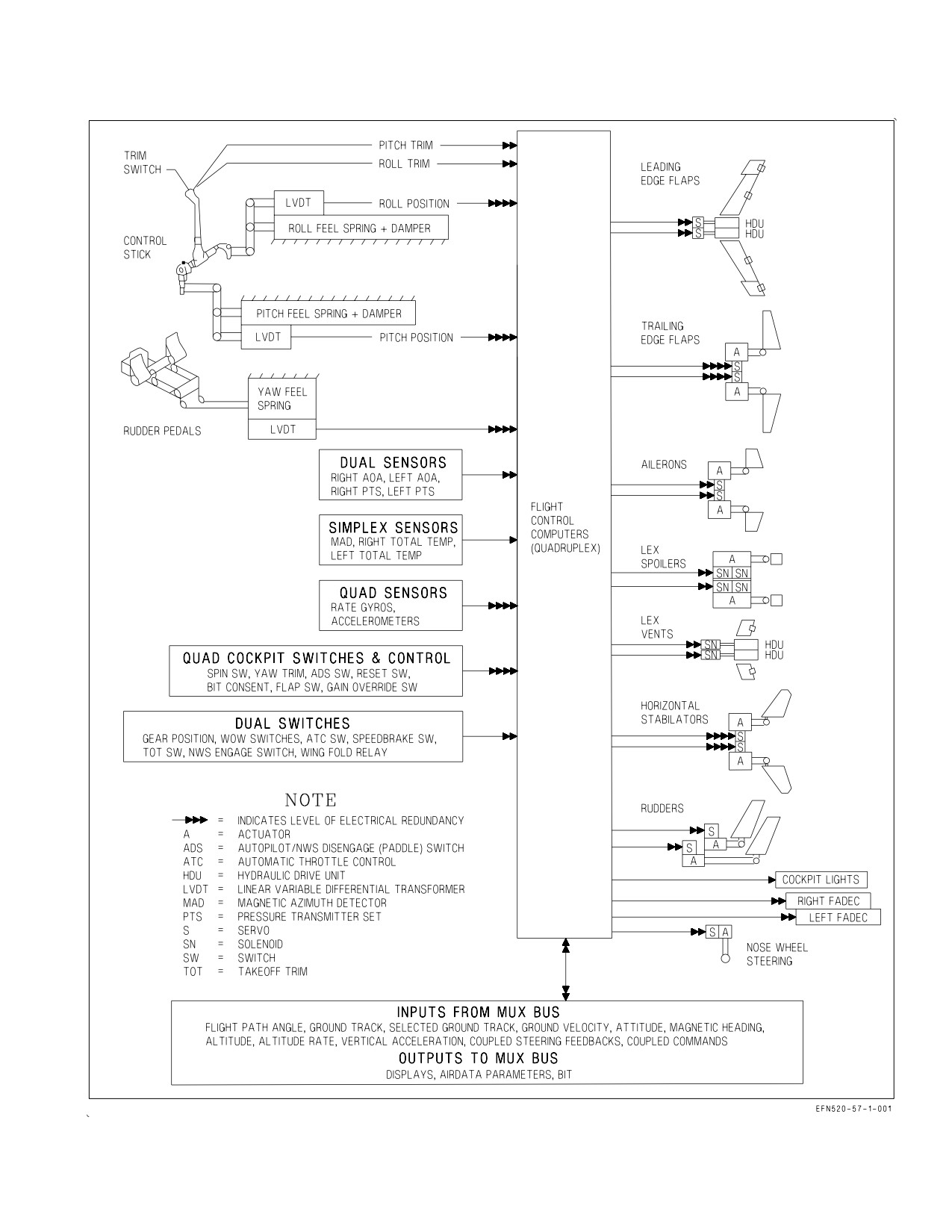
structural limits of the airframe. See figure 2-19 for a functional diagram of the flight control system.
2.10.1 Flight Control Surfaces. The aircraft has 12 primary flight control surfaces including leading
edge flaps (LEFs), trailing edge flaps (TEFs), ailerons, twin rudders, horizontal stabilators, and
spoilers. LEFs, TEFs, ailerons, and stabilators can be moved both symmetrically or differentially for
pitch and roll control. Flight control surface deflection limits are shown in figure 2-20.
Pitch control is accomplished with symmetric stabilators and, in some conditions, with rudder toe-in
or rudder flare. Roll control is accomplished with combinations of ailerons, differential stabilators,
differential LEFs, and differential TEFs dependent on flight condition and CAS operating mode. The
twin rudders deflect symmetrically for directional control. There is no dedicated speedbrake surface.
Instead, a ″speedbrake function″ is provided by partial deflection of several of the primary flight
control surfaces.
Hydraulic power to all flight control surface actuators is supplied by HYD 1 and HYD 2. Stabilator
and TEF actuators are powered simultaneously by one HYD circuit from each system. All other
actuators are powered by a single primary HYD circuit, with backup hydraulic power available through
a hydro-mechanical switching valve. See the Hydraulic System section, specifically the Hydraulic Flow
Diagram, to determine which HYD circuits power each flight control surface actuator.
Surface
Deflection limits *
Aileron
25° TEU to 42° TED
Rudder
40° left or right
Stabilator
24° TEU to 20° TED
LEF
5° LEU to 34° LED
TEF
8° TEU to 40° TED
LEX Spoilers
0° or 60° TEU
* Tolerance ±1°, or ±3° for spoilers.
Figure 2-19. FCS Surface Deflections
2.10.1.1 Spoilers. The spoilers are mounted on top of the fuselage near the aft end of the LEX. The
spoilers are controlled by the FCCs and have two fixed positions: 0° (down) or 60° TEU. The 60° TEU
position is activated by the speedbrake function or when more than 15° TED stabilator is commanded
(forward stick) above 22° AOA to aid in recovery from high AOA.
2.10.2 FCCs - Flight Control Computers. Two flight control computers (FCC A and FCC B) provide
the computations which implement the aircraft’s flight control laws. A four-channel architecture is
used to provide FCS redundancy. Each FCC contains two individual central processing units (CPUs),
which each run one channel of the FCS. CH 1 and CH 2 are resident in FCC A, with CH 3 and CH 4
in FCC B.
I-2-61
ORIGINAL
A1-F18EA-NFM-000
Figure 2-20. Flight Control System Functional Diagram
I-2-62
ORIGINAL
A1-F18EA-NFM-000
Most inputs to the FCCs (rate gyros, accelerometers, air data sensors, stick and rudder pedal
position sensors) are quad-redundant, one input for each channel. Each of the four CPUs runs
independent and parallel flight control computations. Sensor inputs as well as CPU outputs are
continuously monitored by the FCCs for agreement. When there is disagreement, the erroneous signal
is discarded, if possible.
Rate and acceleration data are provided by two independent Attitude and Heading Reference Sets
(AHRS), one for each FCC. Each AHRS has two sets of ring laser rate gyros and two sets of
accelerometers, which provide four independent sources of pitch, roll, and yaw rate information, and
four independent sources of normal and lateral acceleration. The AHRS units have the capability to
provide attitude, heading, and longitudinal acceleration data, but it is not currently utilized. The
physical rate and acceleration sensors in each AHRS channel are not aligned with the aircraft’s pitch,
roll, and yaw axis. This raw sensor data is converted to the aircraft’s pitch, roll, and yaw axis by
microprocessors internal to each AHRS. As a result of this architecture, a single rate gyro failure in one
channel results in all three axis rates being unusable in that same channel (CAS P, R, Y in one channel
Xd out). Similarly, if any of the accelerometers fail, all acceleration data from that AHRS channel is
unusable (N ACC and L ACC in one channel will both be Xd out).
FCC channel outputs are transmitted to the appropriate flight control actuators and to other aircraft
systems such as the MCs. While FCC computations run in all four channels, all flight control actuators
are not commanded in all four channels. The stabilators and TEF actuators do receive command
signals from all four FCC channels. However, each aileron, rudder, spoiler, and LEF actuator only
receives command signals from two FCC channels, one from FCC A and one from FCC B. The
2-channel actuators on the left side of the aircraft receive inputs from CH 1 and CH 4 while the
2-channel actuators on the right side receive inputs from CH 2 and CH 3. This channel distribution can
be seen on the FCS format.
2.10.2.1 FCC Temperature Monitoring. FCC A contains a thermocouple which monitors the
temperature within the computer and provides a signal to FCC CH 1 and CH 2. If an over-temperature
condition is detected, the FCS HOT caution and caution light come on, and the ″Flight computer hot,
Flight computer hot″ voice alert annunciates. Additionally, FCC A indicates OVRHT on the BIT
status line. In this case, placing the AV COOL switch to EMERG provides emergency ram air cooling
to FCC A and the right TR via a dedicated FCS ram air scoop. FCC B also contains a thermocouple,
but does not set the FCS HOT cautions. The only indication of an over-temperature condition in FCC
B is a BIT status indication of OVRHT.
2.10.2.2 AV COOL Switch. The AV COOL switch is located on the lower right main instrument panel
outboard of the caution light panel.
NORM
FCS ram air scoop retracted.
EMERG Deploys the FCS ram air scoop for emergency ram air cooling of FCC A, the right
TR, and other essential avionics.
Once deployed, the FCS ram air scoop cannot be retracted inflight.
2.10.3 FCS Redundancy and Survivability. Hydraulic redundancy is provided by distributing flight
control actuators among the four HYD circuits. This arrangement minimizes the probability of losing
multiple actuators due to catastrophic damage to any single actuator or its hydraulic lines. Following
a single HYD system failure, the other HYD system is capable of powering the entire FCS. Loss of
HYD 1 or HYD 2 in up and away flight does not affect aircraft control. However, in the takeoff and
I-2-63
ORIGINAL
A1-F18EA-NFM-000
landing configuration, small but controllable roll and/or yaw excursions may be expected as hydraulic
switching valves cycle to their backup circuits.
The primary electrical power source for each FCC channel is a dedicated output from one of two
permanent magnet generators (PMGs). See the Electrical System section for FCC Electrical Redun-
dancy. Should a power interruption occur to any single FCC channel, the FCC power supply
automatically switches to a ″keep alive″ circuit connected directly to the maintenance bus for 7 to 10
seconds. This makes sure that the FCCs have uninterrupted power to maintain full operation during
all predictable electrical bus switching transients.
For survivability, wiring for one channel from each computer is routed through the upper part of the
aircraft with wiring for the other through the lower part of the aircraft. This routing minimizes the
possibility of loss of any one flight control surface due to system failures or battle damage. If a
stabilator actuator fails due to multiple FCS or hydraulic failures, the FCS automatically reconfigures
to maintain 3-axis control and acceptable handling qualities by using the remaining surfaces. There is
no mechanical FCS reversion mode.
2.10.4 CAS Operating Modes. The control augmentation system (CAS) operates in two basic modes:
Powered Approach (PA) and Up-AUTO (UA). Mode selection is controlled by FLAP switch position
and airspeed. With the FLAP switch in HALF or FULL and with airspeed below approximately 240
KCAS, CAS implements flight control laws tailored for the takeoff and landing configuration (PA).
With the FLAP switch in AUTO, CAS implements flight control laws tailored for up and away flight
(UA). If the FLAP switch is left in HALF or FULL, the aircraft automatically transitions from PA to
UA when airspeed increases above approximately 240 KCAS. This is known as ″auto flap retract.″ In
this case, the amber FLAPS light comes on to alert the pilot to check FLAP switch position. The flight
control laws utilized in each mode are tailored to provide maximum maneuverability while maintaining
predictable handling qualities and departure resistance.
2.10.4.1 FLAP Switch. The FLAP switch, located on the lower left main instrument panel, is used to
select the CAS operating mode and to position the TEFs and aileron droop for takeoff and landing.
AUTO
Selects UA operating mode for up and away flight.
HALF
Selects PA operating mode for the takeoff and landing configuration. Sets TEF
deflection and aileron droop to 30° TED (WonW or at approach speed).
FULL
Selects PA operating mode for the takeoff and landing configuration. Sets TEF
deflection and aileron droop to 40° TED (WonW or at approach speed).
2.10.4.2 Flap Position Lights. Three flap position lights, two green and one amber, are located on the
lower left main instrument panel. The green HALF and FULL flap lights are used to indicate FLAP
switch position and are not indications of actual TEF/aileron position. The FCS format should be
referenced to determine actual LEF, TEF, and aileron position.
FLAPS
FLAP switch in HALF or FULL and airspeed above 240 KCAS (auto flap retract),
(amber)
abnormal flap condition (any flap is off or lacks hydraulic pressure), spin detected
by Spin Recovery System, or GAIN switch in ORIDE.
HALF
FLAP switch in HALF and airspeed below 240 KCAS.
(green)
FULL
FLAP switch in FULL and airspeed below 240 KCAS.
(green)
I-2-64
ORIGINAL
A1-F18EA-NFM-000
2.10.5 Control Augmentation System (CAS).
2.10.5.1 Pitch CAS. Pitch CAS (P CAS) utilizes normal acceleration, pitch rate, and AOA feedback,
each scheduled based on aircraft flight conditions, to tailor aircraft response to pilot stick inputs and
to provide stabilator actuator commands. P CAS operates by comparing aircraft response to the pilot’s
longitudinal stick input, driving the stabilator actuators symmetrically until the difference is reduced
to zero.
In UA, with neutral longitudinal stick, comparing pilot input to aircraft response has the effect of
constantly trimming the aircraft to steady-state, hands-off
1g flight, essentially removing the
requirement for manual trim. In maneuvering flight, P CAS modifies aircraft response to stick inputs
creating the effect of changing stick forces to provide pilot cueing. Actual stick forces for a given stick
displacement do not change with flight condition. At high airspeeds, P CAS is a g-command system
requiring 3.5 pounds of stick-force-per-g. At medium airspeeds, P CAS acts as a hybrid pitch rate and
g-command system. Pitch rate feedback is used to increase apparent stick-force-per-g (heavier stick
forces) to cue the pilot that airspeed is decreasing and less g is available. At low airspeed, P CAS is
primarily an AOA command system using AOA feedback above 22° AOA to provide increasing stick
forces with increasing AOA. With large forward stick inputs, P CAS augments nose-down pitch rates
by flaring the rudders and raising the spoilers.
In PA, AOA and pitch rate feedbacks are used to augment inherent airframe pitch damping and
stability. P CAS nulls the difference between the commanded AOA and actual AOA. With neutral
longitudinal stick, P CAS maintains trim AOA. Unlike UA, pitch trim is required in PA to trim the
aircraft on-speed. Rudder toe-in is used to improve longitudinal stability and to aid aircraft rotation
during takeoff or bolter. Rudder toe-in is a function of AOA. At 0° AOA or with WonW, the rudders
are toed-in 40°. Rudder toe-in decreases linearly to 0° of toe at 12° AOA. Additional AOA feedback is
provided above 12° AOA which increases stick forces with increasing AOA to provide stall warning.
Pitch rate feedback helps maintain tight pitch attitude control during turns.
2.10.5.2 Roll CAS. Roll CAS (R CAS) schedules aileron, differential LEF, differential TEF, and
differential stabilator commands in response to lateral stick inputs to achieve the desired roll
characteristics. Roll rate feedback, scheduled based on aircraft flight conditions, is used to augment
inherent airframe roll damping. Differential LEFs and TEFs are only used in UA. The LEFs deflect
differentially up to 5° when below 25,000 feet and above Mach 0.6. Differential TEFs are not used
above 10° AOA or below -5° AOA. At high airspeeds, aileron, differential stabilator and differential
TEF travel are reduced to provide consistent roll rate response and to aid in preventing structural
loads exceedances. At low airspeeds, aileron and differential stabilator travel are reduced with
increasing AOA to minimize adverse yaw. Differential stabilator may also be limited due to pitch
commands which have priority over lateral commands.
With clean wing or A/A missile loadings (no wing tanks), maximum roll rate is limited to
approximately 225°/second. With A/G store or external fuel tank codes set in the armament computer
for any wing station and the pylon rack hooks closed for those stations, maximum roll rate is limited
to approximately 150°/second to avoid exceeding pylon structural load limits. If all stores are shown as
HUNG, roll rate limiting is removed; however, an R-LIM OFF caution appears on the DDI.
R CAS incorporates two features to reduce pitch-roll inertial coupling induced departures. Based on
pitch rate and Mach number, the first feature reduces the roll command when the pilot applies an
I-2-65
ORIGINAL
A1-F18EA-NFM-000
excessive combined lateral/longitudinal stick input. The second feature limits the roll command when
the aircraft is already rolling and longitudinal stick is moved rapidly. This second feature is removed
at low altitude and high speed since available pitch rate does not result in significant pitch-roll inertial
coupling.
2.10.5.3 Yaw CAS. Yaw CAS (Y CAS) uses yaw rate and lateral acceleration feedback to provide
directional axis damping and to augment pilot commands to the twin rudder actuators. A rolling-
surface-to-rudder interconnect (RSRI) adjusted by roll-rate-to-rudder crossfeed (scheduled with
AOA), and lateral acceleration feedback are used to minimize sideslip for roll coordination. To provide
departure resistance and enhanced maneuverability at high AOA, directional stability is augmented
utilizing INS pitch and roll attitudes along with the FCS sensors to synthesize sideslip and sideslip rate
feedback to the ailerons and differential stabilators. These lateral surfaces are used in this sense as
directional controllers by taking advantage of the strong yawing moments they produce at high AOA.
Below 13° AOA, rudder pedal deflections provide yaw by symmetric rudder deflection. At 25° AOA
and above, rudder pedal deflections no longer provide yaw control inputs but instead act entirely as a
roll controller (identical to lateral stick input) by commanding aileron and differential stabilator with
the RSRI commanding the required rudder deflection for roll coordination. Rudder pedal inputs are
summed with lateral stick inputs and this combined input is limited to a value equal to a maximum
lateral stick input. Therefore, applying pedal opposite to lateral stick cancels lateral stick inputs
proportional to the pedal input, e.g., full opposite pedal cancels a full lateral stick command resulting
in zero roll rate. Between 13° and 25° AOA, rudder pedal deflection gradually changes from pure yaw
control to pure roll control. This method of control provides enhanced departure resistance at high
AOA.
Some traditional directional control capability is returned at low airspeed and high AOA only when
the pilot applies lateral stick and rudder in the same direction. This feature starts becoming effective
only at airspeeds below approximately 225 KCAS, from 20° to 40° AOA, but is most effective at
approximately 170 KCAS and 34° AOA. Enabling this feature outside of these conditions would
compromise departure resistance. When this feature is enabled, the sum of lateral stick and rudder
pedal command is no longer limited to a value equal to a full lateral stick input. The excess roll
command is fed to the directional axis to command sideslip. For example, adding full rudder pedal with
a full lateral stick input provides a maximum roll and yaw command. Alternatively, adding lateral stick
to an existing full rudder pedal input has the same effect. The resulting aircraft motion is a highly
controllable nose-high to nose-low reversal.
At high airspeeds, symmetric rudder deflection is reduced and the rudders are toed in to avoid
exceeding vertical tail structural limits.
In PA mode, synthesized sideslip rate feedback augments aerodynamic directional damping and
stability.
2.10.5.4 Flap Scheduling. In UA, LEFs, TEFs, and aileron droop are scheduled as a function of AOA
and air data to optimize cruise and turn performance, to improve high AOA characteristics, and to
provide load alleviation (when required). In general, LEFs start to deflect as AOA increases above
approximately 3°, reaching full deflection (34° LED) by about 25° AOA. In general, TEFs start to
deflect above 2 to 3° AOA, are at full scheduled deflection (approximately 10 to 12° TED) from
approximately 6 to 15° AOA, and begin to retract as AOA increases further. In other words, TEFs are
deflected in the heart of the maneuvering envelope to produce more lift and are retracted at high AOA.
In UA, aileron droop is scheduled to 50% of TEF deflection at low AOA and to 0° at high AOA.
I-2-66
ORIGINAL

A1-F18EA-NFM-000
In UA, flap scheduling is altered slightly based on the presence of wing tanks. With wing tanks
installed, TEF deflection is slightly lower at most flight conditions. LEFs and TEFs typically begin to
deflect at slightly slower Mach but follow the same trends as those mentioned above.
In PA, LEFs are scheduled as a function of AOA to maximize lift. TEFs are scheduled as a function
of airspeed for load alleviation but should be at maximum scheduled deflection at approach speed. In
PA, aileron droop is scheduled with TEF deflection. Following field takeoff or catapult launch,
TEF/aileron droop is latched for 10 seconds after the transition to WoffW. This feature is designed to
improve catapult launch characteristics by ensuring the flaps do not retract immediately after launch.
However, if approximately 190 KCAS is exceeded prior to expiration of the 10 second timer, the TEFs
and aileron droop do begin to retract for loads alleviation. LEF, TEF, and aileron droop scheduling are
shown in figure
2-21.
FCS Mode
Configuration
Status
LEF Position
TEF Position AIL Droop
WonW
3° LED
2° TED
1° TED
50% of TEF
Scheduled
No Wing Tanks
Scheduled
(<10° AOA),
WoffW
with
with M,AOA
0°
M,AOA,Alt
(>15° AOA)
UA
WonW
3° LED
4° TED
2° TED
50% of TEF
Scheduled
Wing Tanks
Scheduled
(<10° AOA),
WoffW
with
with M,AOA
0°
M,AOA,Alt
(>15° AOA)
WonW
15° LED
30° TED
30° TED
Flaps HALF
Scheduled
30° TED
30° TED
WoffW
with AOA
(on-speed)
(on-speed)
PA
WonW
15° LED
40° TED
40° TED
Flaps FULL
Scheduled
40° TED
40° TED
WoffW
with AOA
(on-speed)
(on-speed)
Figure 2-21. Flap Schedules
2.10.6 Speedbrake Function. The aircraft is not fitted with independent speedbrake surfaces. A
″speedbrake function″ is provided to increase drag by partial deflection of several of the aircraft’s
primary flight control surfaces: ailerons, rudders, TEFs, and spoilers. The stabilators are commanded
to counter pitch transients during speedbrake extension and retraction. The full speedbrake function
can only be commanded in UA.
At subsonic speeds in UA, the speedbrake function flares the rudders and symmetrically raises the
ailerons TEU to approximately 95% of the capability of each surface at the given flight conditions.
This makes sure approximately 5% of surface authority is available for yaw and roll control. If needed,
rudder and aileron priority is given to yaw and roll commands. TEFs are also symmetrically lowered
to further increase drag and to counter the loss of lift caused by deflecting the ailerons TEU. The
spoilers are raised to the full up 60° position only when the speedbrake command reaches 75%. At
subsonic speeds, the stabilator is used to offset any pitch transients that occur due to the deflection of
all speedbrake surfaces except the spoiler. Delaying spoiler deflection until 75% allows the pilot to use
partial speedbrakes for speed modulation, while avoiding minor spoiler induced pitch transients.
I-2-67
ORIGINAL
A1-F18EA-NFM-000
At supersonic speeds in UA, speedbrake surface deflections are changed. The rudders are not
deflected above 1.05 M due to vertical tail loads. The ailerons and TEFs are not deflected above 1.1 M
due to a lack of effectiveness. The spoilers are therefore deflected immediately upon speedbrake
actuation, since they are the only effective surface at these conditions. At supersonic speeds, the
stabilator is used to counter spoiler deployment. The speedbrake function is completely disabled above
1.5 IMN.
In UA, the speedbrake function is ramped out above 16° AOA or below -9° AOA to preserve
lateral-directional stability and between -3.0 to -1.5g for airframe loads.
In PA, the speedbrake function is disabled with WoffW. With WonW and the FLAP switch in HALF
or FULL, the speedbrake function only deploys the spoilers. While the spoilers can be deployed during
landing rollout or aborted takeoff, the drag increase is minimal, and rollout distance is not appreciably
decreased. With WonW and the FLAP switch in AUTO, full extension of the speedbrake function
commands 20° of rudder flare, 23° of TEU aileron, 7° of TED TEF, 60° of spoiler, and a 2° TED
stabilator change.
2.10.6.1 Speedbrake Switch. The speedbrake switch, located on the inboard side of the right throttle
grip, is used to enable/disable the speedbrake function, e.g., extend/retract the speedbrake surfaces.
The forward and center positions are detented, while the aft position is spring-loaded back to center
and must be held. In the F/A-18F (trainer configuration), the rear cockpit speedbrake switch has
override priority over the front cockpit switch.
Forward
Retracts speedbrake surfaces (full retraction in 2 seconds).
(unmarked)
Center
Stops speedbrake surfaces at an intermediate position.
(unmarked)
Aft
Extends speedbrake surfaces (full extension in 2 seconds).
(unmarked)
NOTE
• If the speedbrake switch is held or fails in the aft position for more
than 5 minutes, the speedbrake switch is declared failed, and the FCS
caution is set. If the switch is failed or is held in the aft position when
the FCS RESET button is pushed, the speedbrake surfaces are
retracted, Xs are set on the DEGD row of the FCS page, and the
speedbrake function is disabled for the remainder of the flight.
• If the front cockpit switch is held in the aft position during any FCS
RESET attempt, the speedbrake switch is declared failed; the speed-
brake surfaces are retracted; and the speedbrake function is disabled
for the remainder of the flight. This allows the speedbrake surfaces to
be retracted before the 5 minute timer expires, if the front cockpit
switch is stuck in the aft position.
• In the F/A-18F (trainer configuration), if the rear cockpit switch fails
in the aft position, the
5 minute timer must expire before the
speedbrake surfaces can be retracted with the FCS RESET button.
I-2-68
ORIGINAL
A1-F18EA-NFM-000
2.10.6.2 SPD BRK Light. The green SPD BRK light is located on the left warning, caution, and
advisory panel on the main instrument panel. The SPD BRK light comes on anytime the speedbrake
surfaces are not fully retracted.
2.10.7 G-Limiter Considerations. In order to understand what protection the aircraft’s g-limiter
provides, pilots must understand the difference between ″design limit-g″ and ″reference load factor (Nz
REF).″ See the Acceleration Limitations chart in the Operating Limitations chapter for a plot of Nz
REF versus gross weight, for g-limiter specifics, and for gross weight related g-restrictions.
2.10.7.1 Design Limit-g. The aircraft was designed to sustain a limit-g of +7.5g or -3.0g (symmetric)
only at or below its fighter design gross weight of 42,097 lb. At higher gross weights, design limit-g is
reduced to keep from exceeding the structural limitations of the airframe. An ″overstress″ is defined as
a g-level that exceeds the design limit-g at the aircraft’s current gross weight. Above 42,097 lb gross
weight, design limit-g is reduced by the aircraft’s relative gross weight (42,097/GW), such that the
positive design limit is +7.5g * (42,097/GW) and the negative design limit is -0.4 * (positive limit-g). At
the aircraft’s maximum gross weight (66,000 lb), design limit-g is only +4.8g or -1.9g.
Due to the increased airframe and pylon loads that accompany high-g rolling maneuvers, the aircraft
also has a design limit-g for abrupt full-stick rolls (FSR). Abrupt FSRs are defined as full lateral stick
in less than 1 second. The positive design FSR limit is +6.0g below 42,097 lb GW and 80% of the
symmetric design limit-g above 42,097 lb. The negative design FSR limit is -1.0g at all gross weights.
At 66,000 lb GW, the positive design FSR limit is only +3.8g.
2.10.7.2 Reference Load Factor (Nz REF). Reference load factor (Nz REF) is the value that the MC
uses to set the g-limiter when outside of the transonic g-bucket (described below). With increasing
gross weight, Nz REF is the same as design limit-g until the gross weight where +5.5g (-2.2g) is
available (57,405 lb GW). Above 57,405 lb GW, Nz REF is held fixed at +5.5g (-2.2g) in order to assure
that the pilot always has those g-levels available even if they would result in an overstress. Since the
g-limiter may not prevent an overstress at gross weights above 57,405 lb, the pilot must be responsible
for preventing an overstress in this gross weight region.
2.10.7.3 G-Limiter. The g-limiter essentially limits the amount of positive and negative g that can be
commanded by the pilot at a particular gross weight in order to prevent an aircraft overstress. Once the
pilot reaches the stick displacement required to attain the Nz REF g-limit, further stick inputs do not
increase g. This is commonly called ″being on the limiter.″ Once the stick is relaxed to the limit
displacement, g-control below Nz REF is regained. The g-limiter functions to maintain both the
positive and negative Nz REF limits.
During abrupt longitudinal stick inputs, g-limiter overshoots are not uncommon. G-limiter over-
shoots of up to +0.5g or -0.2g are allowed and do not constitute an over-g. An ″over-g″ is defined as a
g-level which exceeds the overshoot thresholds and sets MSP code 811 (positive exceedance) or 925
(negative exceedance). An over-g condition requires a postflight inspection to determine if an
″overstress″ occurred.
For rolling maneuvers commenced above the positive FSR limit, the g-limiter also provides some
protection. In this region, the g-limiter attempts to reduce commanded-g towards the positive FSR
limit to prevent an overstress. However, if the rate of lateral stick input exceeds the capability of the
g-limiter, an actual rolling overstress may result without setting an 811 MSP code (set only if the
symmetric over-g threshold is exceeded). The g-limiter treats rolling maneuvers with less than ¾ inch
lateral stick as symmetric maneuvers.
I-2-69
ORIGINAL
A1-F18EA-NFM-000
A G-LIM 7.5G caution, accompanied by the FLIGHT CONTROLS, FLIGHT CONTROLS voice
alert, is set for any of the following: FUEL XFER, CAUT DEGD, MC2, SMS failure, or an invalid fuel
quantity. A G-LIM 7.5G caution indicates that the positive symmetrical command limit has been set
to +7.5g regardless of gross weight or stores loading. If the G-LIM 7.5G caution is set, the pilot must
limit commanded g-level to prevent an overstress.
Very high g-onset rates are possible with rapid aft stick movement, with
or without g-limiter override. A very high g-onset rate can cause imme-
diate loss of consciousness (G-LOC) without the usual warning symptoms
of tunnel vision, greyout, and blackout. The effects of G-LOC may last 20
seconds or longer after the g level is reduced to near 1.0g.
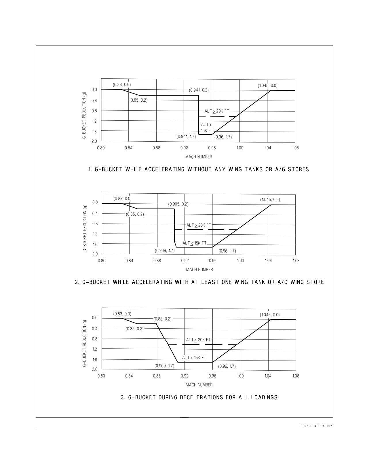
2.10.7.4 G-Bucket. Due to the aerodynamic phenomenon known as transonic pitch-up, the g-limiter
incorporates a g-bucket designed to prevent an aircraft positive over-g during transonic deceleration.
In the g-bucket, the g-limiter reduces the positive command g-limit below Nz REF (figure 2-22). This
reduction is a maximum of 1.0g above 20,000 feet, and 1.7g below 15,000 feet. For example, if Nz REF
is +7.5g and altitude is ≤15,000 feet, the g-limiter only allows +5.8g to be commanded while in the
g-bucket. The symmetrical command limit is never reduced below +4.5g.
NOTE
• G-bucket reduction reduces maximum commandable-g.
• Magnitude of transonic pitch-up increases as rate of Mach change
increases. High drag loadings with idle power settings generally have
the largest transonic pitch-ups. High drag loadings (e.g., A/G stores)
have a g-bucket that extends into a lower Mach range.
• Largest measured transonic pitch-up was 2.2g for <15,000 feet. This
magnitude pitch-up was seen on both A/A and A/G loadings.
The 0.2g deep mini-g-bucket extension in the Mach 0.85 to Mach 0.94 range was added in the FCC
OFP to protect against over-g in that region.
The Mach range for the deeper part of the g-bucket is dependent on external stores configuration.
The deeper part of the g-bucket is entered at Mach 0.905 accelerating (with at least one wing tank or
A/G wing store) or at Mach 0.941 accelerating with no wing tanks or A/G stores. Regardless of stores
loading, when decelerating, the g-bucket is entered at Mach 1.045 and is exited at Mach 0.83.
Full stick roll (FSR) limits are reduced in the g-bucket to 80% of (Nz REF minus no more than a
1.0g reduction). For example, if Nz REF is +7.5g, Mach is 0.95, and altitude is ≤15,000 feet, the
g-limiter sets the FSR limit to 80% of (Nz REF minus 1.0) even though the bucket depth is 1.7g.
If the pilot wants to have maximum-g available during a turning maneuver (e.g., the merge), or avoid
the deeper part of the g-bucket, IMN should be 0.90 or less (with at least one wing tank or A/G store),
or 0.93 or less (clean or with A/A stores). Note that even though the 0.2g mini-g-bucket might be active,
flight testing has shown the g-level will be at or slightly above Nz REF.
I-2-70
ORIGINAL
A1-F18EA-NFM-000
Figure 2-22. G-Limiter G-Bucket Reductions in Maximum Commandable G-Level
I-2-71
ORIGINAL
A1-F18EA-NFM-000
2.10.7.5 G-Limiter Override. A g-limiter override feature can be enabled to allow a 33% increase in
the command g-limit for emergency use (allows a 10g command at 7.5g Nz REF). G-limiter override is
selected by momentarily pressing the paddle switch when the stick is near the full aft limit. When
g-limiter override is selected, a G-LIM OVRD caution is set along with a 927 MSP code. Override is not
disengaged until the stick is returned to near the neutral position.
2.10.7.6 Roll Rate Limiting. Roll rate limiting is enabled in R CAS when external wing tanks or A/G
stores are mounted on wing pylons (hooks closed). If any A/G store indicates HUNG, a R-LIM OFF
caution is set and roll rate limiting is removed. In this case, higher than normal roll rates are possible
and may exceed the structural limitations of the airframe/pylons if pilot-imposed lateral stick limits
are not applied.
2.10.8 Air Data Function. The air data function is provided by the FCCs and not a separate
computer. The FCCs receive input from pitot-static sensors, total temperature sensors, the angle of
attack probes, the standby altimeter barometric setting, and the mission computers. The FCC air data
function applies appropriate source error corrections to the air data sensor inputs and calculates
accurate true altitude, airspeed, Mach number, AOA, and outside air temperature (OAT). Computed
air data is used internally by the FCC control augmentation system (CAS) and is also supplied to the
MCs for IFF altitude reporting, weapon system calculations, and landing gear wheels warning, to the
FADECs for engine control, and to the ECS controller for ECS scheduling and fuel tank pressurization
and vent.
2.10.8.1 Pitot-Static/Total Temperature Probes. Two combined pitot-static/total temperature
probes are mounted on the left and right forward fuselage. Each probe contains one pitot pressure
source, two static pressure sources, and a total temperature sensor. One of the static pressure sources
from each probe is connected together and pneumatically averaged. This average static source is
provided to the left and right pressure transmitter sets along with the corresponding pitot pressure
source. The left pressure transmitter set provides pitot-static input to FCC CH 1 and 4 with the right
providing input to FCC CH 2 and 3. The FCC air data function corrects sensed pitot and static
pressures for position error to provide accurate true air data for FCC calculations, MC calculations, and
display in the HUD. The pitot pressure source and the second static pressure source from the left probe
are used to drive the standby flight instruments (altitude, airspeed, and VSI). The second static
pressure source from the right probe is unused.
Each pitot-static probe also contains an integral total temperature sensor. Each total temperature
sensor converts sensed temperature to an electrical signal. The output of the left total temperature
sensor is sent to FCC CH 2, with the right to FCC CH 4. The FCCs use total temperature to calculate
OAT. Each pitot-static/total temperature probe is electrically heated to prevent icing.
2.10.8.2 AOA Probes. Two AOA probes are mounted on the left and right forward fuselage. Each
probe mechanically measures local AOA by aligning with the airstream. An integral AOA transmitter
set converts the mechanical input to a two-channel electrical signal which is sent to the FCCs. The left
AOA transmitter set provides input to FCC CH 1 and 4 with the right to FCC CH 2 and 3. The FCC
air data function corrects the sensed local AOA to a true AOA and provides the output to the MC for
display on the HUD. FCS CH 4 supplies the AOA signal which drives the AOA indexer lights and the
approach lights.
It is possible to damage and jam an AOA probe such that it continues to send signals to the FCCs.
FCC software is designed to minimize flying qualities degradation in the event of a stuck/jammed AOA
probe. The FCCs incorporate an AOA estimator which is used to identify the good AOA probe if one
is damaged. If an AOA probe split is transient, the estimator is used to identify the good probe and no
I-2-72
ORIGINAL
A1-F18EA-NFM-000
cautions are set. If the AOA probe split persists, an FCS caution is set, AOA is Xd in all four channels,
and the estimator is used for FCC calculations. See the HUD Symbology Degrades with Air Data
Function Failure paragraph and Part V for more details on AOA failures. Each AOA probe and AOA
probe cover are electrically heated to prevent icing.
2.10.8.3 PITOT ANTI ICE Switch. The PITOT ANTI ICE switch is located on the ECS panel on the
right console. This switch is used to power the electric heaters for the pitot-static/total temperature
probes, the AOA probes, and the AOA probe covers. All heaters are thermostatically controlled to
prevent damage to their corresponding sensors. With WonW, the thermostat set points are reduced to
prevent damage when cooling airflow is not provided.
ON
Pitot and AOA heaters on manually (WonW or WoffW).
AUTO
Pitot and AOA heaters on automatically with WoffW. Heaters off with WonW.
Failure of both AOA probe heaters in icing conditions may cause a sharp
uncommanded nose down attitude, uncontrollable by normal stick forces
or paddle switch actuation.
2.10.9 Flight Controls.
2.10.9.1 Stick. A traditional center mounted control stick is used to provide pitch and roll inputs to
the FCS. Since there is no mechanical linkage between the stick and the FCCs or the flight control
surfaces, stick feel is provided by two feel-spring assemblies and two eddy current dampers. The feel
spring assemblies provide a linear stick force versus stick displacement gradient in each axis. Two
4-channel position sensors, one in each axis, measure stick displacement and send longitudinal and
lateral stick commands to the FCCs proportional to stick displacement. Stick force and displacement
are listed in figure 2-23 for full stick travel. The eddy current dampers provide stick motion damping
in each axis. Additionally, the control stick is mass balanced to minimize longitudinal stick movement
resulting from accelerations normally experienced during catapult launch.
In the F/A-18F (trainer configuration), a control stick is also fitted in the rear cockpit and is
mechanically linked to the one in the front cockpit.
Displacement Force
Direction
(in)
(lbs)
Forward
2.5
20
Stick
Aft
5.0
37
Left/Right
3.0
13
Pedal
Left/Right
1.0
100
Figure 2-23. Stick and Pedal Travel Limits
2.10.9.2 Rudder Pedals. Two rudder pedals (left and right) are used to provide directional inputs to
the FCS for yaw/roll control inflight or NWS control with WonW. Since there is no mechanical linkage
I-2-73
ORIGINAL
A1-F18EA-NFM-000
between the rudder pedals and the FCCs or the flight control surfaces, rudder pedal feel is provided
by two feel-spring assemblies. The feel spring assemblies provide a linear pedal force versus
displacement gradient. Two 4-channel position sensors, one on each pedal, measure pedal displace-
ment and send directional commands to the FCCs proportional to pedal displacement. Rudder force
and displacement are listed in figure 2-23 for full pedal travel. The rudder pedals are also used to
provide NWS commands and to actuate toe-operated wheel brakes.
In the F/A-18F (trainer configuration), two rudder pedals are also fitted in the rear cockpit but are
not mechanically linked to the rudder pedals in the front cockpit. Pedal inputs from either cockpit are
summed together and transmitted to the FCCs. A half pedal input from the front cockpit and a half
pedal input from the rear cockpit results in a full rudder pedal command to the FCCs. Similarly,
opposing rudder pedal inputs in each cockpit cancel each other.
2.10.9.2.1 RUD PED ADJ Lever. A RUD PED ADJ lever, located on the center pedestal in each
cockpit, is spring loaded to the up and locked position. When the lever is held down, the rudder pedals
are unlocked and can be moved forward and aft in ½ inch increments. Both pedals are spring loaded
to move aft and must be pushed forward to the desired position. Releasing the RUD PED ADJ lever
locks the pedals in the new position.
• Restrain the rudder pedals during adjustment. Unrestrained rudder
pedals may damage the rudder pedal mechanism.
• Ensure the rudder pedals are locked in position after adjustment.
Failure to lock the rudder pedals may result in uncommanded forward
rudder pedal movement inflight.
2.10.9.3 Stick Grip FCS Controls. The FCS controls located on the stick grip include the pitch and
roll trim switch, the NWS button, and the autopilot/NWS disengage switch. See figure 2-24. In the
F/A-18F (trainer configuration), the FCS controls on the rear cockpit stick grip are identical to those
in the front cockpit.
2.10.9.3.1 Pitch and Roll Trim Switch. The pitch and roll trim switch is located on the top right of
the stick grip. Movement of the pitch and roll trim switch electrically biases the FCCs and does not
reposition the stick.
Forward
Trims nose-down.
Aft
Trims nose-up.
Left
Trims left-wing-down.
Right
Trims right-wing-down.
Pitch and roll trim inputs can be made incrementally or held for faster trim rates. In UA, little if any
pitch trim is required due to the automatic trimming function provided by P CAS. In PA, pitch trim
is required to trim for on-speed AOA. Lateral trim is typically only required immediately after takeoff
or following changes in lateral weight asymmetry (fuel and/or stores). Pitch trim is not monitored for
I-2-74
ORIGINAL
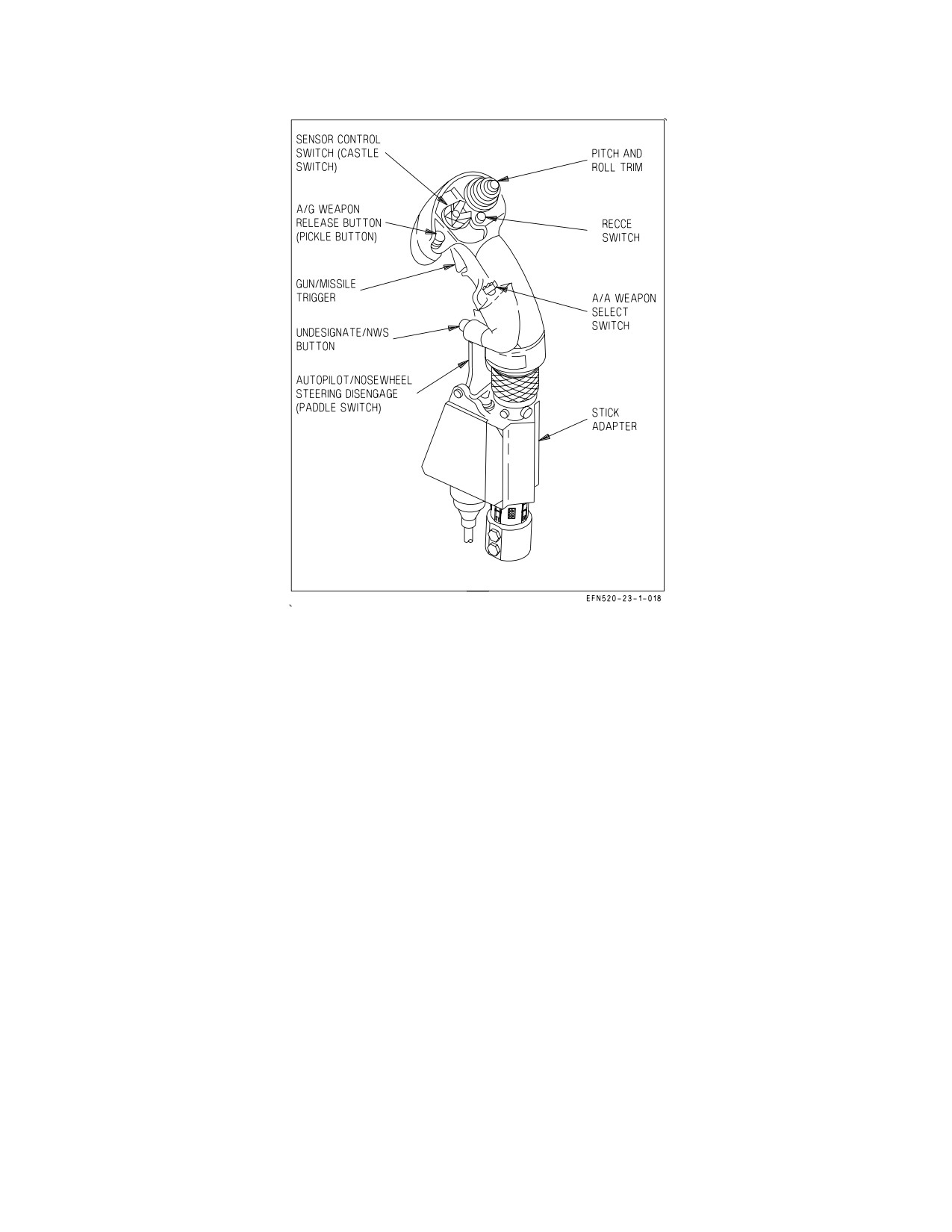
A1-F18EA-NFM-000
Figure 2-24. Stick Grip FCS Controls
runaway trim. However, roll trim is monitored for a stuck switch. If the trim switch is held or is stuck
in the left or right position for more than 40 seconds, the FCS caution is set and the roll trim function
of the switch is disabled for the remainder of the flight. Roll trim can be faded to zero by pushing and
holding the FCS RESET button or TO/TRIM button for approximately 4 seconds.
2.10.9.3.2 NWS Button. The undesignate/nosewheel steering button is located on the front of the
stick grip. The NWS button is used to engage NWS modes, as described in the NWS System
paragraphs in the Utility Hydraulic Functions section. The undesignate function of the NWS button
is described in the Weapon Systems Controls section.
2.10.9.3.3 Paddle Switch. The autopilot/NWS disengage switch, commonly called the ″paddle
switch,″ is located on the lower front of the stick grip. The paddle switch is used to disengage NWS with
WonW, to disengage all autopilot modes with WoffW, and to enable g-limiter override with WoffW. To
enable g-limiter override, the paddle switch must be momentarily pressed with the stick near the aft
limit.
2.10.9.4 RUD TRIM Knob. The RUD TRIM knob is located on the FCS panel on the left console in
the front cockpit only. Movement of the RUD TRIM knob electrically biases the FCCs and does not
reposition the rudder pedals. Rudder trim authority is ±10° and ±22.5° of rudder surface deflection in
UA and PA, respectively. PA rudder trim authority is set to allow zero pedal forces during a HALF flap,
single engine approach. Yaw trim is zeroed by mechanically centering the RUD TRIM knob when the
T/O TRIM button is pushed with either WonW or WoffW.
I-2-75
ORIGINAL
A1-F18EA-NFM-000
2.10.9.5 T/O TRIM Button. The T/O trim button is located in the center of the RUD TRIM knob on
the FCS panel on the left console. With WonW, holding the T/O TRIM button pressed drives pitch
trim to 4° TEU stabilator, roll trim to neutral, and yaw trim to neutral by mechanically centering the
RUD TRIM knob. Depending on initial trim position the T/O TRIM button may need to be pressed
for up to 4 seconds. When these takeoff trim settings are reached, the TRIM advisory is displayed on
the LDDI for as long as the T/O TRIM button is held depressed. With WoffW, pressing the T/O TRIM
button for as long as 4 seconds drives roll trim to neutral, centers the RUD TRIM knob, but does not
affect pitch trim.
2.10.10 Yaw Rate Warning Tone. In UA (flaps AUTO), a yaw rate warning tone is provided to alert
the pilot of excessive yaw rate that may lead to an aircraft departure. The yaw rate warning tone is
generated by the FCCs and is initiated at 40°/second yaw rate with a 1 Hz pulse rate. The tone pulse
rate increases linearly as yaw rate approaches 60°/second, where the pulse rate remains constant at 10
Hz. There is no yaw rate warning tone in PA.
2.10.11 AOA Warning Tone. An AOA warning tone is provided to alert the pilot of excessive AOA
that may lead to aircraft settle and/or departure.
With flaps HALF or FULL, the AOA warning tone is triggered at 14° AOA with a 1 Hz pulse rate.
The tone pulse rate increases linearly as AOA approaches 35°, where the pulse rate remains constant
at 10 Hz.
With MC OFP H3E AND UP, with flaps AUTO, the AOA warning tone is triggered when the AOA
limits corresponding to the FLY lateral weight asymmetry are exceeded. A 500 ft-lb buffer is applied
to the lateral weight asymmetry threshold when triggering the tone to account for fuel slosh. If there
is an AOA failure, or more than one fuel quantity is invalid and/or weapon station indicates HUNG on
stations 2 − 10 (FLY value removed), the tone will not be triggered and the AOA TONE caution will
be displayed.
2.10.12 Spin Recovery System. The aircraft incorporates an automatic spin detection and recovery
system. A spin is declared when both of the following conditions are met: (1) airspeed is below
approximately 120 ±15 KCAS and (2) the yaw rate threshold is exceeded. The yaw rate threshold is
exceeded, for example, if a 15 to 20°/second yaw rate persists for approximately 15 seconds or a 50 to
60°/second yaw rate persists for approximately 2 seconds. For cases where the pilot is intentionally
commanding a high AOA roll (e.g., pirouette) the yaw rate threshold persistence is increased from 15
seconds to 25 seconds.
Immediately following a low-speed maneuver less than 77 KCAS (e.g., tail-slide), airspeed limits for
SPIN logic are opened to 180 KCAS or 12 seconds, whichever comes first. During this time, the normal
acceleration feedback gain is removed to avoid excess coupling, and spin mode arrows will be displayed
to aid recovery if yaw rate exceeds the threshold.
Once a spin has been detected, the spin recovery system places the SPIN MODE recovery displays
on both DDIs (figure 2-25), illuminates the amber FLAPS light, and drives the LEFs to 34° LED and
the TEFs to 4° TED. The displayed spin recovery arrow always indicates the proper direction for
anti-spin lateral stick inputs whether the spin is upright or inverted. Anti-spin lateral stick inputs are
aileron-into for upright spins and aileron-opposite for inverted spins. When lateral stick is placed with
the arrow, automatic spin recovery mode (ASRM) is engaged. With ASRM engaged, all CAS feedback
and control surface interconnects are removed, providing full aileron, rudder, and stabilator authority
for spin recovery. If the stick is neutral or is moved in the wrong direction, the SPIN MODE formats
remain displayed, the LEFs and TEFs remain deflected, but the FCS remains in CAS, and ASRM is
not engaged.
I-2-76
ORIGINAL
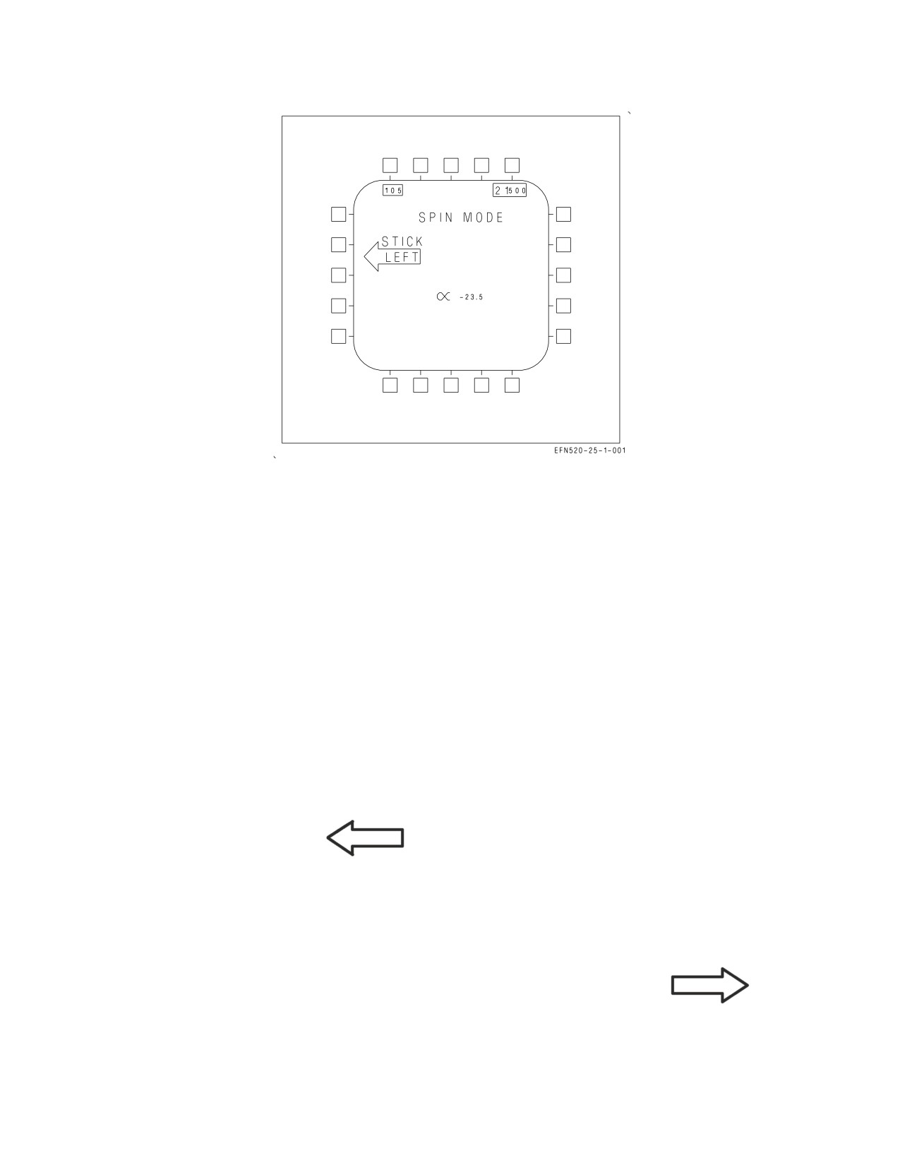
A1-F18EA-NFM-000
Figure 2-25. SPIN Recovery Display
If ASRM is engaged during spin recovery, the spin arrow is removed and the FCS automatically
reverts to CAS when either of the following conditions are met: (1) airspeed is above approximately 245
KCAS or (2) the yaw rate threshold is no longer exceeded. After recovery, LEFs and TEFs return to
normal scheduling, and the SPIN MODE formats are replaced with the MENU page after 2 seconds.
NOTE
During highly oscillatory spins or spins that transition from upright to
inverted or from inverted to upright, the SPIN MODE displays may
disappear momentarily.
2.10.12.1 Spin Recovery Displays. When the spin recovery system detects an upright left spin or an
inverted right spin, a left spin arrow appears on both DDIs to indicate the proper direction of the
anti-spin lateral stick input.
SPIN MODE
STICK
LEFT
When the spin recovery system detects an upright right spin or an inverted left spin, a right spin
arrow appears on both DDIs to indicate the proper direction of the anti-spin lateral stick input.
SPIN MODE
STICK
RIGHT
When lateral stick is placed in the direction of the arrow, the word ″ENGAGED″ appears below the
words ″SPIN MODE″ on both DDIs to indicate that ASRM has been successfully engaged.
I-2-77
ORIGINAL
A1-F18EA-NFM-000
SPIN MODE
is replaced by
SPIN MODE
ENGAGED
When the SPIN MODE formats appear on the DDIs, airspeed is always displayed in the upper left
corner, with altitude in the upper right and AOA in the lower center. See figure 2-23.
2.10.12.2 SPIN Switch. The SPIN switch is located on the right side of the main instrument panel.
The switch is guarded to prevent actuation. The SPIN switch was designed to allow for activation of
a manual spin recovery mode (MSRM). However, with all CAS feedback and control surface
interconnects removed, flight in MSRM will result in a departure and, once departed, will prevent
departure and/or spin recovery. SPIN arrow logic and ASRM functionality have been optimized and
thoroughly flight tested to produce accurate spin mode detection and positive spin recovery.
RCVY
Prohibited.
NORM
ASRM available when a spin is detected.
Selection of manual spin recovery mode (SPIN switch in RCVY) seri-
ously degrades controllability, will prevent recovery from any departure
or spin, and is prohibited.
2.10.13 Stabilator Failure Control Law Reconfiguration. Stabilator reconfiguration consists of
additional control laws which augment baseline CAS control laws to compensate for the complete loss
of a single stabilator. Stabilator reconfiguration is automatically enabled following the detection of a
complete stabilator failure (3 or more FCS Xs in a single stabilator or a dual HYD circuit failure - HYD
1B/2A or 1A/2B). If hydraulics are intact, the failed stabilator is driven to 2° TEU and locked.
Following a dual HYD circuit failure, the failed stabilator must be driven to the locked position by
aiding airloads. If unaiding airloads are applied, actuator mechanization prevents the stabilator from
moving further away from the locked position.
The reconfigured control laws are designed to compensate for the loss of the pitch and roll
contribution of the failed stabilator. In the pitch axis, pitch commands to the remaining stabilator are
doubled to produce more pitching moment. In PA, rudder toe-in and rudder flare are also used to aid
the pitching moment capability of the remaining stabilator. In the roll axis, differential stabilator
commands are disabled. A stabilator-to-rolling-surface interconnect is used to compensate for the roll
generated by single stabilator movement. In PA, this interconnect is stabilator to aileron. In UA, it is
stabilator to aileron and differential TEF. At high airspeed in UA, differential LEFs are also used. In
the yaw axis, the baseline differential stabilator portion of the RSRI continues to be used to counter
the yaw generated by single stabilator movement.
2.10.14 GAIN ORIDE. GAIN ORIDE allows the pilot to select a set of fixed CAS gains when an FCS
malfunction prevents normal CAS gain scheduling (e.g., loss of AOA or pitot-static data). With the
GAIN switch in ORIDE, the FCCs use fixed values for speed, altitude, and AOA depending on the
position of the FLAP switch. These fixed gains cause the LEFs, TEFs, and aileron droop to be driven
I-2-78
ORIGINAL

A1-F18EA-NFM-000
to the fixed positions shown in figure 2-26. GAIN ORIDE should generally provide acceptable handling
qualities at flight conditions which approximate the fixed gains. At flight conditions that deviate from
the fixed gains, a slight degradation in handling qualities should be expected. Refer to chapter 11 for
details. The aircraft stalls at a lower than nominal AOA since the LEFs are fixed. Transition to or from
the landing configuration should be performed at 180 KCAS. For best results, maintain on-speed AOA
during the approach and landing.
Flight with GAIN ORIDE selected is prohibited above 10° AOA or above 350 KCAS (flaps AUTO),
200 KCAS (flaps HALF), or 190 KCAS (flaps FULL) to ensure control system stability and to reduce
the potential for departure. When GAIN ORIDE is selected, the amber FLAPS light comes on along
with either the CRUIS advisory (flaps AUTO) or the LAND advisory (flaps HALF or FULL). Alpha
tone is disabled in GAIN ORIDE.
Fixed Gains
LEF
TEF
AIL Droop
FLAP Switch
(°LED)
(°TED)
(°TED)
Mach
KTAS
Feet
°AOA
AUTO
5
4
2
0.80
459
39,000
3.5
HALF
21
30
30
0.23
151
500
8.1
8.1
FULL
21
40
40
0.21
139
500
Figure 2-26. GAIN ORIDE Flap Positions and Gain Schedules
2.10.14.1 GAIN Switch. The GAIN switch, located on the FCS panel on the left console, is used to
select GAIN ORIDE. The switch is guarded in the NORM position to prevent inadvertent actuation.
ORIDE
Selects fixed CAS gains according to FLAP switch position.
NORM
Selects normal CAS gain scheduling.
2.10.15 FCS Failures. The FCS detects failures through three types of BIT: initiated (IBIT), periodic
(PBIT), and maintenance (MBIT). FCS IBIT is performed during Before Taxi Checks to run a
thorough test of the system prior to flight. PBIT is a less thorough test of the FCS and runs
continuously when other BITs are not running. MBIT is typically run by maintenance personnel and
is the most comprehensive test of the FCS.
FCS failures are annunciated by any or all of the following indications: the FCS caution, the FCES
caution light, the ″Flight controls, Flight controls″ voice alert, FCS format Xs, and/or BIT Logic
Inspection (BLIN) codes. FCS format Xs and BLIN codes identify the location and type of failure.
However, not all FCS related components/functions are covered by Xs on the FCS format matrix. For
such components/functions, valid BLIN codes may be the only indication of the location of the failure.
Therefore, until the nature of the failure is determined, BLIN codes that appear without Xs should be
treated with the same level of concern as those that do.
Typically, BLIN codes that have three digits or less are generated by PBIT, e.g., 341. Four digit and
five digit BLIN codes are generated by FCS IBIT, e.g., 4573 and 10165.
2.10.15.1 FCES Caution Light. The Flight Control Electronic Set (FCES) caution light is located on
the lower right caution lights panel. The primary purpose of the FCES caution light is to alert aircrew
I-2-79
ORIGINAL
A1-F18EA-NFM-000
of critical FCS related failures when MC1 is failed. When MC1 is failed, the normal DDI FCS related
cautions are not generated and the FCS format is not available for troubleshooting. When MC1 is
operative, the FCES caution light is merely a secondary indication of an FCS related failure. The
specific FCS cautions which also trigger the FCES caution light are listed in figure 2-27.
2.10.15.2 FCS RESET Button. The FCS RESET button is located on the FCS panel on the left
console. This button is used to perform several FCS related functions. Following detection of FCS
related hardware and/or software failures (e.g., FCS Xs and/or BLIN codes), pressing the FCS RESET
button commands a reset of FCC failure detection circuitry. If the FCS related failure was momentary
and no longer exists, an FCS RESET (a) restores the failed actuator/component, (b) removes all FCS
failure indications (FCS caution, FCES caution light, and Xs; preflight BLIN codes only), and (c)
displays the RSET advisory for 10 seconds to indicate a successful reset. If the failure remains (a) the
failed actuator/component is not restored, (b) the FCS failure indications return, and (c) the RSET
advisory is displayed for 10 seconds to indicate an unsuccessful reset. In other words, the FCS
RESET button does not fix a detected failure; it merely allows components to be
restored and failure indications to be removed, if and only if the failure no longer exists.
Prior to takeoff (cycle to WoffW), a successful FCS RESET automatically clears all BLIN codes.
Inflight or post-flight, however, BLIN codes are not automatically cleared with a successful FCS
RESET in order to preserve this data for maintenance troubleshooting. Inflight and post-flight BLIN
codes can be cleared, if desired, by pushing the FCS RESET button simultaneously with the paddle
switch.
Additionally, the FCS RESET button is used in conjunction with the FCS BIT consent switch to
enter the FCS exerciser mode.
2.10.15.3 FCS Exerciser Mode. The FCS exerciser mode is incorporated to aid hydraulic system
warming during cold weather starts. The exerciser mode allows hydraulic fluid and hydraulic seals to
warm towards normal operating temperatures without making large surface movements. Large surface
movements with a cold hydraulic system can result in hydraulic seal damage, leaks, and loss of fluid.
On the ground, the FCS exerciser mode is initiated by simultaneously holding the FCS BIT consent
switch in the ON position while pressing the FCS RESET button. When initiated, the mode cycles the
stabilators, flaps, ailerons, and rudders through 20% of full travel for 10 cycles in 20 seconds. The
operation can be stopped prior to 20 seconds by pressing the paddle switch.
During cold weather starts, avoid activating any hydraulic actuated system for two minutes after
both engines are online. This allows hydraulic fluid to warm both systems and prevents hydraulic seal
damage and potential hydraulic leaks. If the aircraft has not flown within 4 hours with ambient
temperatures below -18°C (0°F), up to three selections of the FCS exerciser mode may be required in
order to obtain a successful FCS RESET (after the initial 2 minute warmup).
In standard or warm conditions, do not initiate the FCS exerciser mode
multiple times in an attempt to get a successful FCS RESET. In such
conditions, multiple initiations may excessively elevate hydraulic system
temperatures, increasing actuator and hydraulic pump seal wear and
potentially decreasing component life.
I-2-80
ORIGINAL

A1-F18EA-NFM-000
2.10.15.4 FCS BIT Consent Switch. The FCS BIT consent switch is located above the right console
beneath the right canopy sill. The switch is used in conjunction with the FCS BIT option or the FCS
RESET button to initiate FCS IBIT or the FCS exerciser mode, respectively. See the FCS Initiated
BIT (IBIT) section at the end of chapter 2 for details.
ON
When held (for at least 2 seconds) during selection of the FCS option, initiates
FCS IBIT. When held during a press of the FCS RESET button, initiates FCS
exerciser mode.
OFF
FCS IBIT and FCS exerciser mode not selected.
2.10.15.5 FCS Related Cautions. FCS related cautions shown in figure 2-27
are described in the
Warning/Caution/Advisory Displays in Part V.
Associated Cockpit Indications
Caution
″Flight Controls,
Master Caution
Master Caution
Flight Controls″
Light
Tone
FCES Light
Voice Alert
AOA
X
X
X
Air Data
X
X
ATC Fail
X
X
X
AUTO PILOT
X
X
P CAS
X
X
X
R CAS
X
X
X
Y CAS
X
X
X
CHECK TRIM
X
X
CK FLAPS
X
X
FC AIR DAT
X
X
X
FCS
X
X
X
Note 2
FCS HOT
X
Note 1
Note 1
FLAPS OFF
X
X
X
FLAP SCHED
X
X
X
G-LIM 7.5G
X
X
G-LIM OVRD
X
X
HYD 5000
X
X
X
NWS
X
X
X
R-LIM OFF
X
X
RIG
X
S/W CONFIG
X
X
NOTES
1. The FLIGHT COMPUTER HOT, FLIGHT COMPUTER HOT voice alert and FCS HOT light on the
caution lights panel are activated when the FCS HOT caution is set.
2. Also displayed when any aileron, stabilator, or rudder actuator failed off (Xd out and a ″bold X″ over
the surface position on FCS Status Display).
Figure 2-27. FCS Related Cautions and Cockpit Indications
I-2-81
ORIGINAL
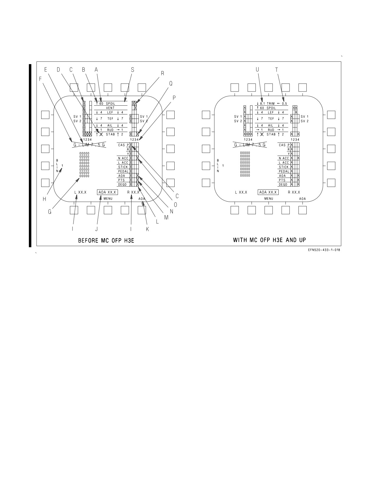
A1-F18EA-NFM-000
Figure 2-28. FCS Status Display
2.10.16 FCS Status Display. When an FCS failure has occurred, the FCS status display (figure 2-28)
can be used to determine the location and type of failure. The FCS status display is selected by the FCS
option on the SUPT MENU. For FCS components/functions which are displayed in the matrix, an ″X″
is displayed in the failed channel(s) along with a corresponding BLIN code. For FCS components/
functions which are not displayed in the matrix, BLIN codes are the only indication of failure location.
A. Surface Position: In degrees from streamline for all surfaces. Tolerance is ±1° for all surfaces.
B. Surface Arrow: Direction of surface deflection relative to the surface hinge point except for
stabilators. For stabilators, surface arrow indicates trailing edge position.
C. Column of Xs: An entire FCC channel is failed due to a processor fault or loss of power.
D. Bold X across surface position: Surface failed; FCCs are no longer commanding movement of
that surface in any channel.
E. G-LIMX.XG: ″X.X″ is the current Nz REF value as calculated by the MC. This value is
decremented if in the transonic g-bucket. INVALID is displayed in this position if the interface
between FCC CH 1, FCC CH 3, and the MC is invalid. In this case, all data on the display is invalid.
During FCS IBIT, G-LIM0.0G is displayed in this position.
F. Bold X over G-LIMX.XG: Nz REF data from the MC is invalid or out of range, and Nz REF has
defaulted to +7.5g. This X also appears when gross weight is above 57,405 lb, indicating that Nz REF
has been set to +5.5g even though this may result in an overstress.
I-2-82
ORIGINAL
A1-F18EA-NFM-000
G. BLIN Codes. Up to eight FCC BLIN codes are displayed in octal format for each channel. The codes are
displayed in the order of occurrence. If the list exceeds eight, additional codes may be viewed with a memory
inspect of unit 14 or 15 with address 2253.
In-flight Memory Inspect (MI) of FCC (UNIT 14 or 15) addresses (ADDR)
greater than six digits long is prohibited since it may cause all four FCC channels
to shut down which will result in loss of aircraft control.
H. BLIN Code Channel: The FCC channel corresponding to the list of BLIN codes. The channel is
incremented from 1 thru 4 and back to 1 by selecting the BLIN option.
I. L/R XX.X: FCC air data function corrected true AOA for the left and right AOA probes (see AOA Select in
paragraph K below).
J. AOA XX.X: True AOA based on INS data. INS true AOA is displayed for reference only to aid the pilot in
determining which AOA probe is valid when one is damaged. INS true AOA is normally boxed, indicating that
an average of the left and right probes has been selected for display in the HUD and for use by the AOA indexer
lights and approach lights.
K. AOA Select: The AOA option is displayed only when GAIN ORIDE is selected. If one AOA probe is
damaged, the AOA option can be used to select output from the good probe for display in the HUD and for use
by the AOA indexer lights and approach lights. AOA probe selection does not affect the fixed gains used by the
FCCs in GAIN ORIDE.
NOTE
If a single probe is declared invalid (a two channel AOA failure), and that
probe is selected, the AOA indexer lights and the HUD AOA are blanked
immediately.
L. DEGD Xs: An FCC failure has occurred in the Xd channel that is not covered by other matrix Xs. BLIN
codes should be used to determine the degraded FCC channel function.
M. PTS Xs: The static or total pressure data is failed in the Xd channel. If a three channel PTS failure occurs
(three Xs), the FCC control laws use data from the remaining PTS channel. If a total PTS failure occurs (four
Xs), the FCCs use fixed PTS values. If a PTS failure clears, PTS Xs are removed automatically with or without
an FCS RESET attempt.
NOTE
With a four channel PTS failure, HUD airspeed and altitude are blanked.
N. AOA Xs: AOA data failed in the Xd channel. A three or four channel AOA failure sets four Xs (AOA Four
Channel failure). In UA, P CAS uses the AOA estimator for control law scheduling. If a UA failure clears, AOA
Xs are removed automatically with or without an FCS RESET attempt. In PA, P CAS uses a fixed 8.1° AOA
value, and R CAS uses the AOA estimator for control law scheduling. If a PA failure clears, AOA Xs are not
removed until an FCS RESET is attempted.
O. Sensor Xs (CAS P, R, or Y; N ACC, L ACC, STICK, or PEDAL): The corresponding sensor (rate gyros,
normal or lateral accelerometers, stick or pedal position) is failed in the Xd channel. A three or four channel
sensor failure sets four Xs (total sensor failure). However, for a three channel failure, the FCCs average the
remaining channel with the last channel that failed. For N ACC and L ACC only, the FCCs use a single channel
if the signal from the third failed channel exceeds 90% of full range. A single X for CAS P, CAS R, or CAS Y is
not possible. Any single gyro failure in P, R, or Y sets Xs in CAS P, CAS R, and CAS Y for that channel. Similarly,
an AHRS acceleration failure sets Xs in the N ACC and L ACC for that channel. A failed AHRS sets Xs in all
five rows for that channel.
I-2-83
ORIGINAL W/IC 34
A1-F18EA-NFM-000
P. 1 2 3 4: Column legends for each FCC channel. FCC A contains channels 1 and 2 while FCC B
contains channels 3 and 4.
Q. Actuator Xs: The actuator is no longer commanded by the FCC in the Xd channel due to a
detected failure (for all actuators except spoilers). The actuator is still commanded by the other
operating channel(s).
R. SPOIL Xs: A single X is caused by a difference between commanded and actual position or by a
SOV over-current. If a two channel failure (two Xs) was caused by a difference between commanded
and actual position, the FCCs will continue to command the spoilers in both channels. This condition
is indicated by two Xs, a blanked surface position, and no bold surface position X. The vent surface
position value is always blanked.
S. Blank Surface Position: FCCs and/or MCs unable to report actuator position.
T. ROLL TRIM: With MC OFP H3E AND UP, roll trim is displayed in the right column with
WoffW. Arrows indicate trim direction. The roll trim value is dimensionless. Roll trim effects for the
same trim value are different at different airspeeds. The roll trim value provides a quantitative
measure of how much roll trim has been commanded.
U. PITCH TRIM: With MC OFP H3E AND UP, pitch trim is displayed in the left column with
WoffW. Arrows indicate trim direction. The pitch trim value is degrees AOA with flaps in HALF or
FULL and g-level with flaps in AUTO.
2.11 AFCS - AUTOMATIC FLIGHT CONTROL SYSTEM
The AFCS or autopilot provides three basic functions: pilot relief, coupled steering, and data link
control.
Different pilot relief modes are provided for the pitch and roll axes. Pitch-axis pilot relief modes
include barometric altitude hold (BALT), radar altitude hold (RALT), and flight path attitude hold
(FPAH). Roll-axis pilot relief modes include roll attitude hold (ROLL), ground track hold (GTRK),
ground track select (GSEL), heading hold (HDG), and heading select (HSEL).
Coupled steering modes allow the roll-axis to be coupled to a TACAN station (CPL TCN), to a
waypoint (CPL WYPT), to the azimuth steering line (CPL ASL), or to bank angle (CPL BNK).
Data link control modes include automatic carrier landing (ACL) and vector (VEC).
2.11.1 AFCS Mode Selection. Selection of the various autopilot (A/P) modes is accomplished from
the A/P sublevel of the CNI format on the UFCD. Before any autopilot mode can be selected, bank
angle must be less than 70°, pitch attitude must be less than 45°, and the A/P sublevel must be
displayed on the UFCD. The left column of the A/P sublevel displays the couple (CPL) option and the
pitch-axis pilot relief mode options: BALT, RALT, and FPAH. The right column displays the roll-axis
pilot relief mode options: ROLL, GTRK, and HDG. See figure 2-29.
An autopilot mode is enabled by selecting the corresponding option on the UFCD. Once selected, a
highlighted box appears around the option and the corresponding autopilot advisory appears on the
LDDI. If an option is not available, it is not displayed.
Once in the GTRK mode, subsequent selection of the GTRK option enables the GSEL mode (GSEL
replaces GTRK on the UFCD). Once in the HDG mode, subsequent selection of the HDG option
enables the HSEL mode (HSEL replaces HDG on the UFCD).
I-2-84
ORIGINAL
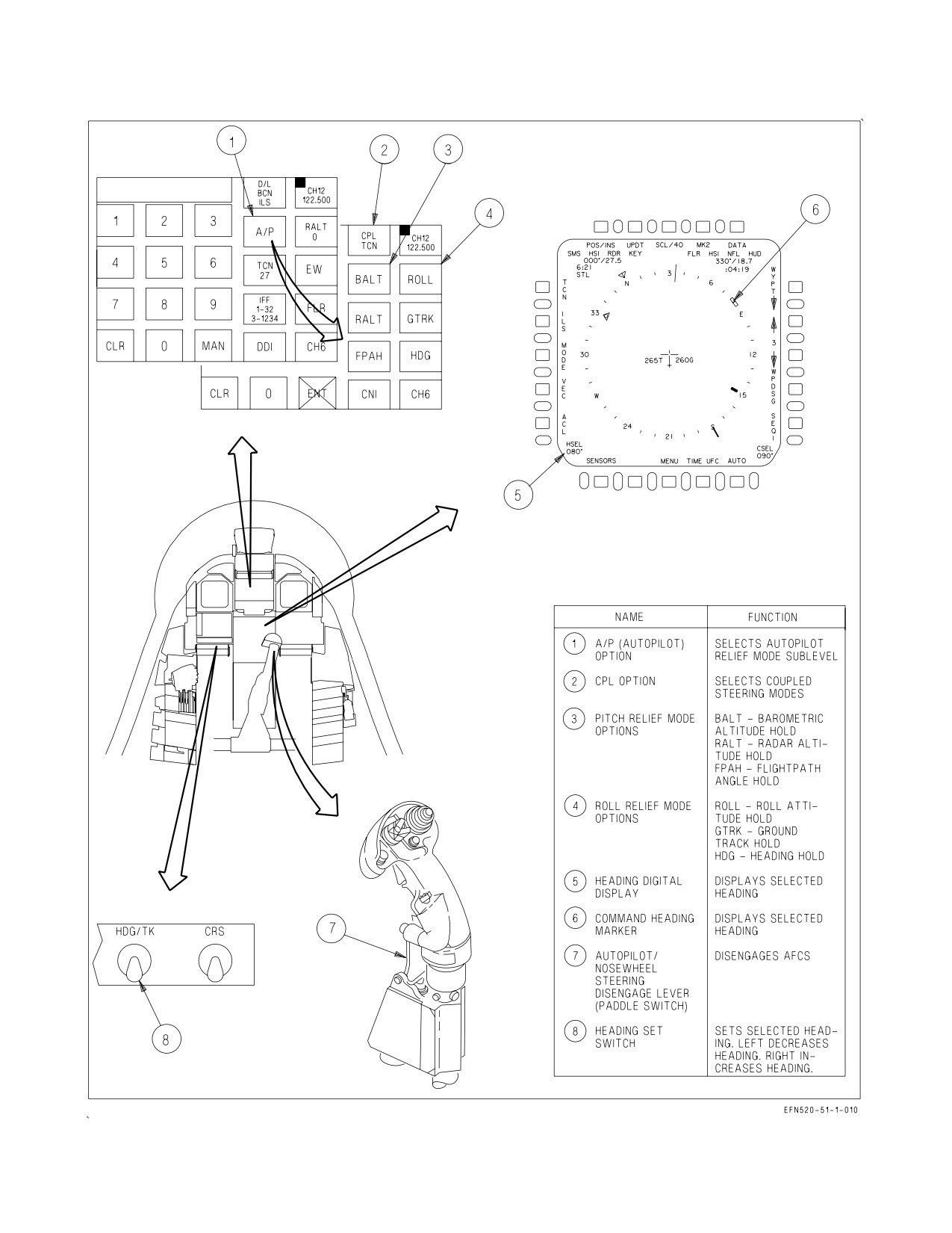
A1-F18EA-NFM-000
Figure 2-29. AFCS Controls and Indicators
I-2-85
ORIGINAL
A1-F18EA-NFM-000
2.11.2 Basic Autopilot. The basic or default autopilot mode is FPAH/HDG. When any autopilot
mode is requested from the UFCD, the AFCS first engages FPAH/HDG and then engages the
requested mode. This makes sure that the AFCS is controlling both the pitch and roll axis whenever
an autopilot mode is engaged.
2.11.3 AFCS Mode Deselection. Autopilot modes can be disengaged by either reselecting (unboxing)
the UFCD option or by actuating the paddle switch. If an autopilot mode is unboxed on the UFCD, the
AFCS reverts to the basic autopilot mode in that axis and the AUTO PILOT caution illuminates. If the
stick is moved longitudinally with BALT or RALT engaged or laterally with CPL engaged, the AFCS
reverts to the basic autopilot mode in that axis as the AUTO PILOT caution illuminates. The basic
autopilot mode, however, cannot be disengaged (unboxed) from the UFCD and must, therefore, be
disengaged with the paddle switch. Paddle switch actuation is the only means to make sure that all
autopilot modes have been completely disengaged.
2.11.4 Pitch-Axis Pilot Relief Modes. Any of the pitch-axis pilot relief modes can be engaged in
conjunction with any coupled steering mode (except ACL) or with any roll-axis pilot relief mode.
However, only one pitch-axis mode can be selected at a time. If one pitch-axis mode is requested while
another is engaged, the AFCS switches to the requested mode.
2.11.4.1 BALT - Barometric Altitude Hold. When BALT is engaged, the baro-inertial altitude at the
time of engagement is captured and maintained. While the mode is engaged, this reference altitude
cannot be changed. Longitudinal stick inputs or trim changes disengage BALT, and the AFCS reverts
to FPAH and the selected roll-axis mode.
2.11.4.2 RALT - Radar Altitude Hold. RALT is not available above 5,000 feet AGL. When RALT is
engaged, the radar altitude at the time of engagement is captured and maintained. While the mode is
engaged, this reference altitude cannot be changed. Longitudinal stick inputs or trim changes
disengage RALT, and the AFCS reverts to FPAH and the selected roll-axis mode.
2.11.4.3 FPAH - Flight Path Angle Hold. When FPAH is engaged, the flight path angle at the time
of engagement is captured and maintained. This reference flight path angle can be changed by
longitudinal stick inputs (stick sensitivity similar to CAS) or by pitch trim changes (2°/sec in flaps
AUTO or 0.5°/second in flaps HALF or FULL). When pilot inputs cease, the flight path attitude at
release is captured and maintained.
2.11.5 Roll-Axis Pilot Relief Modes. Any of the roll-axis pilot relief modes can be engaged in
conjunction with any pitch-axis pilot relief mode. However, only one roll-axis mode can be engaged at
a time. If one roll-axis mode is requested while another is engaged, the AFCS switches to the requested
mode.
2.11.5.1 ROLL - Roll Attitude Hold. When ROLL is engaged, the roll attitude at the time of
engagement is captured and maintained. This reference roll attitude can be changed by lateral stick
inputs or roll trim changes (stick and trim sensitivity similar to CAS). When pilot inputs cease, the roll
attitude at release is captured and maintained.
2.11.5.2 GTRK - Ground Track Hold. When GTRK is engaged, aircraft response depends on the roll
attitude at the time of engagement. If roll attitude is less than ±5°, ground track is captured and
maintained. If roll attitude is greater than or equal to ±5°, roll attitude is captured and maintained.
While in GTRK, the aircraft responds to lateral stick or roll trim inputs (stick and trim sensitivity
similar to CAS). When pilot inputs cease, GTRK holds roll attitude (if greater than or equal to ±5°)
or ground track (if less than ±5°).
I-2-86
ORIGINAL
A1-F18EA-NFM-000
2.11.5.3 GSEL - Ground Track Select. The desired ground track angle is selected by slewing the
command heading marker with the HDG/TK switch, located to the left of the MPCD. When GSEL is
engaged, the aircraft turns from the existing ground track through the smallest angle to the selected
ground track. While in GSEL, the aircraft responds to lateral stick inputs. However, the selected
ground track angle is not changed by stick inputs, so the aircraft returns to the selected ground track
angle upon stick release.
2.11.5.4 HDG - Heading Hold. When HDG is engaged, aircraft response depends on the roll attitude
at the time of engagement. If roll attitude is less than ±5°, magnetic heading is captured and
maintained. If roll attitude is greater than or equal to ±5°, roll attitude is captured and maintained.
While in HDG, the aircraft responds to lateral stick or roll trim inputs (stick and trim sensitivity
similar to CAS). When pilot inputs cease, HDG holds roll attitude (if greater than or equal to ±5°) or
magnetic heading (if less than ±5°).
2.11.5.5 HSEL - Heading Select. The desired heading is selected by slewing the command heading
marker with the HDG/TK switch, located to the left of the MPCD. When HSEL is engaged, the
aircraft turns from the existing heading through the smallest angle to the selected heading. While in
HSEL, the aircraft responds to lateral stick inputs. However, the selected heading is not changed by
stick inputs, so the aircraft returns to the selected heading upon stick release.
2.11.6 CPL - Coupled Steering Modes. The coupled steering modes couple the aircraft in the
roll-axis only. If the CPL option is selected, the AFCS disengages any currently engaged roll-axis pilot
relief mode. The AFCS has the ability to couple to the following sources: a waypoint, waypoint
courseline, or offset aimpoint (CPL WYPT); to a TACAN station or TACAN courseline (CPL TCN);
or to an auto sequence (CPL SEQ#). Refer to chapter 24 for detailed navigation steering information
on waypoint/OAP, auto sequential, and TACAN steering.
2.11.7 Coupled Data Link Modes. The AFCS can couple to data link commands in one of two modes:
ACL and VEC. With ACL boxed on the HSI format, the CPL P/R option appears on the A/P sublevel
when pitch/roll couple capability is available. Selecting the CPL P/R option couples the aircraft to
pitch and roll commands for a Mode 1 carrier approach. With VEC boxed on the HSI format, selecting
the CPL option couples the aircraft (roll-axis only) to data link steering commands. Refer to chapter
24 and the Tactical Manual for detailed information on the ACL and VEC modes.
2.11.8 AFCS Related Caution and Advisories. The AUTO PILOT caution and the following AFCS
related advisories are described in the Warning/Caution/Advisory Displays in Part V:
• BALT
• GSEL
• HSEL
• CPLD
• GTRK
• RALT
• FPAH
• HDG
• ROLL
2.12 WEAPON SYSTEMS CONTROLS
All of the primary controls for the aircraft’s weapon systems (weapons, sensors, and displays) are
located on the front cockpit throttles and stick, the rear cockpit throttles and stick (trainer configured
F/A-18F), or the rear cockpit hand controllers (missionized F/A-18F). This concept, hands on throttles
and stick (HOTAS), allows the aircrew to manipulate the weapon systems without removing the hands
from the aircraft’s primary flight controls. Additionally, the canopy sill DISP switch(es) and the rear
cockpit grab handle switches provide secondary controls for dispensing expendables from the ALE-47
self-protect system.
I-2-87
ORIGINAL
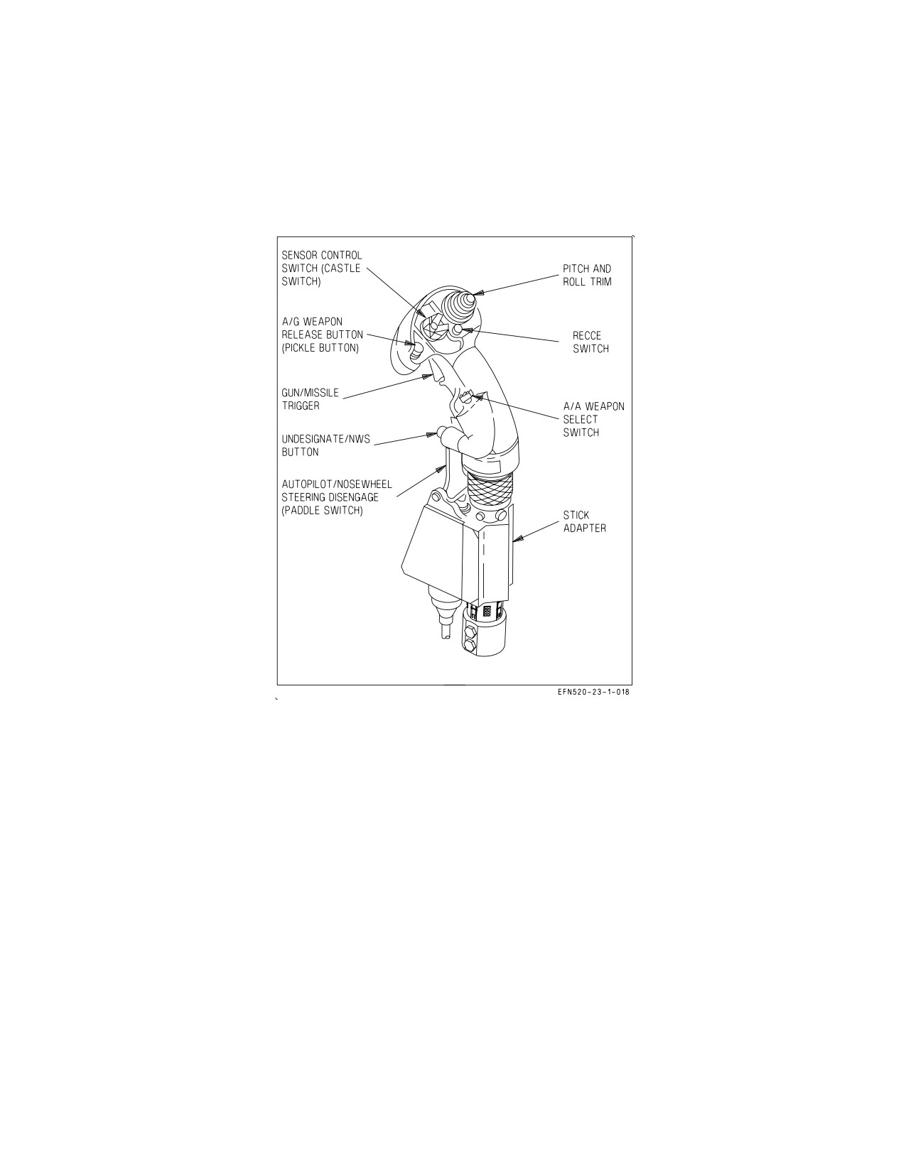
A1-F18EA-NFM-000
Detailed descriptions of the functionality of the weapon systems controls are contained in the
Tactical Manual, F/A-18EA-TAC Series.
2.12.1 Stick Grip Switches/Controls (Front Cockpit). The weapon systems controls located on the
front cockpit stick grip are the A/A weapon select switch, the sensor control switch, the gun/missile
trigger, the A/G weapon release button, and the undesignate/NWS button. See figure 2-30.
Figure 2-30. Stick Grip Switches/Controls
2.12.1.1 A/A Weapon Select Switch. The A/A weapon select switch, located on the left side of the
stick grip, is spring loaded to the center/up position. The weapon select switch is used to select the
desired A/A weapon and can be used to enter A/A master mode. When the weapon select switch is
actuated while in NAV or A/G master mode, the A/A master mode is automatically entered, the RDR
ATTK format is automatically displayed on the RDDI, and the appropriate A/A weapon/radar format
is selected. Once in the A/A master mode, actuating the weapon select switch merely changes the
selected A/A weapon/radar format.
Center
Neutral
Forward
Selects AIM-7 and the corresponding radar format.
Down
Selects AIM-9 and the corresponding radar format.
Aft
Selects A/A GUN and the gun acquisition mode (GACG).
Inward
Selects AIM-120 and the corresponding radar format.
I-2-88
ORIGINAL
A1-F18EA-NFM-000
Selection of an A/A missile initiates launch preparation of the priority missile, if more than one is
carried and brings up the corresponding radar format (e.g., scan volume presets). Subsequent selection
steps to the next available missile in the priority sequence.
2.12.1.2 Sensor Control Switch. The sensor control switch, commonly called the ″castle″ switch, is
located on the top center of the stick grip and is spring loaded to the center/up position. The castle
switch is used to assign throttle designator controller (TDC) priority to a particular cockpit display or,
once air combat maneuvering (ACM) mode functionality is enabled, to select a particular ACM mode.
Center
Neutral
Forward
Assigns TDC priority to the HUD in NAV or A/G master mode. In A/A
master mode, selects the boresight acquisition mode (BST) and enables
ACM mode functionality.
Forward (twice
Selects/deselects EMCON.
within 0.5 seconds)
Depress/release then
Assigns TDC priority to the UFCD in all master modes. If the top level
forward (within 1
CNI, a CNI sublevel, or a data entry format is displayed, selects the last
second)
displayed DDI format.
Left
Assigns the TDC to the LDDI in all master modes. With ACM mode
functionality enabled in A/A master mode, selects the wide acquisition
mode (WACQ).
Right
Assigns the TDC to the RDDI in all master modes. With ACM mode
functionality enabled in A/A master mode, selects the automatic acquisi-
tion mode (AACQ).
Aft
Assigns the TDC to the MPCD in all master modes. With ACM mode
functionality enabled in A/A master mode, selects the vertical acquisition
mode (VACQ).
When the TDC is assigned to a display which cannot accept TDC priority, automatic format
initialization occurs, typically selecting the format which is most commonly used on that particular
display (e.g., RDR ATTK on the RDDI). With TDC assignment, certain displays (e.g., RDR ATTK,
FLIR, etc.) perform a specific action (e.g., track, break track, etc.) when the castle switch is
subsequently bumped toward that display.
2.12.1.3 Trigger. The gun/missile trigger, located on the front of the stick grip, has two detented
positions.
First
Initiates strike camera automatic mode operation (based on the selected A/G
Detent
weapon) and if CVRS is running, commands HUD recording.
Second
In A/A master mode, fires the gun or selected A/A missile. Activates AGI protec-
Detent
tion. In A/G master mode, fires the gun or the laser, if either is selected. Com-
mands the HUD event marker.
I-2-89
ORIGINAL
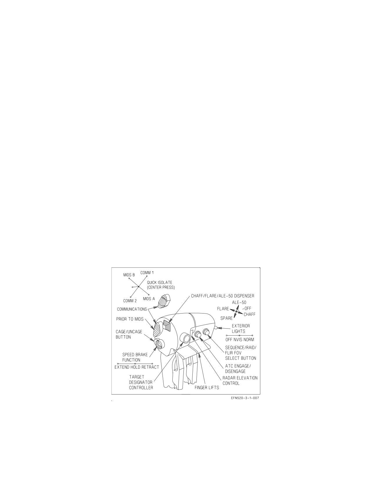
A1-F18EA-NFM-000
2.12.1.4 A/G Weapon Release Button. The A/G weapon release button, commonly called the
″pickle″, is located on the top center of the stick grip to the left of the castle switch. The pickle is used
to command weapon release while in A/G master mode. The pickle also initiates AGI protection, strike
camera automatic mode operation, and, if CVRS is running, commands HUD recording and the HUD
event marker.
2.12.1.5 Undesignate/NWS Button. The undesignate/NWS button is located on the lower front of
the stick grip. In NAV or A/G master mode, the undesignate button undesignates all A/G designated
targets and commands the radar and FLIR to break lock, if either is tracking. If TDC priority is
assigned to the FLIR format, pressing the button twice in 1 second selects/deselects FLIR velocity
vector slave (VVSLV) pointing mode. In A/A master mode, the undesignate button creates a launch
and steering (L&S) target designation. Subsequent actuation steps target designation to the next
priority trackfile or to a second designated trackfile (DT2), if one exists. If ACM mode functionality is
enabled, the undesignate button exits the ACM mode and returns the radar to the previous search
mode.
2.12.2 Stick Grip Switches/Controls
(Trainer Configured F/A-18F). In the F/A-18F
(trainer
configuration), the front and rear cockpit stick grips are identical. However, the rear cockpit trigger
and A/G weapon release button are not functional. The rear cockpit A/A weapon select switch does not
automatically select A/A master mode. From the rear cockpit, A/A master mode must be entered by
actuation of the A/A master mode light. The front and rear cockpit control sensor switches are
functionally identical, including ACM mode selection. However, the rear cockpit TDC can be assigned
to a sensor different from the front cockpit TDC. The systems controlled by the stick grip
switches/controls respond to the last crewmember action taken from either cockpit.
2.12.3 Throttle Grip Switches/Controls (Front Cockpit). The weapon systems controls located on
the front cockpit throttle grips are the chaff/flare/ALE-50 dispense switch, the cage/uncage button, the
throttle designator controller (TDC), the radar elevation control, and the raid button. See figure 2-31.
Figure 2-31. Throttle Grip Switches/Controls (Front Cockpit)
2.12.3.1 Chaff/Flare/ALE-50 Dispense Switch. The chaff/flare/ALE-50 dispense switch is located
on the top inboard side of the right throttle. The switch is used to dispense expendables from the
ALE-47 and ALE-50 self-protect systems.
I-2-90
ORIGINAL
A1-F18EA-NFM-000
Forward
Provides semi-automatic consent. Dispenses chaff singles (C/F mode).
Aft
Initiates the selected manual program. Dispenses flare singles (C/F mode).
Up
Dispenses a single ALE-50 decoy and provides transmit enable.
Down
Not functional
2.12.3.2 Cage/Uncage Button. The cage/uncage button is located on the rear inboard side of the
right throttle. In NAV master mode and A/G master mode (AUTO delivery), the cage/uncage button
is used to cage and uncage the velocity vector. Depending on master mode and TDC priority
assignment, the cage/uncage button can be used to (1) cage/uncage weapons, (2) command a radar
STT, (3) toggle between weapon modes, or (4) reset sequenced HARM targets.
(18E OFP) With the velocity vector caged, data such as the flight path/pitch ladder and steering
information is displayed near the center of the HUD despite large yaw rates and/or crosswind angles.
2.12.3.3 TDC - Throttle Designator Controller. The TDC is located on the front right side of the
right throttle. It is used to control the positioning of the acquisition cursor or the slewing of a particular
sensor or weapon (e.g., FLIR or Maverick). The TDC can be pressed for target designation. When held
pressed (action slew) or released (no-action slew), the fore-aft and left-right movement of the TDC
sends X-Y slew commands to the display or to the sensor/weapon to which TDC priority is assigned.
2.12.3.4 Radar Elevation Control. The radar elevation control is located on the front left side of the
right throttle. Momentary actuation changes the elevation of the radar antenna in
1,000
foot
increments at the range where the cursor is positioned on the RDR ATTK format. Press and hold
produces a faster elevation change.
Up
Raises the radar antenna/scan volume.
Center
Neutral
Down
Lowers the radar antenna/scan volume.
2.12.3.5 RAID Button. The RAID button is located on the left side of the left throttle. Depending on
master mode and TDC priority assignment, the RAID button can be used to (1) sequence between
available HARM targets, (2) toggle between narrow and wide field of view (FOV) for the FLIR or
Maverick, or (3) select/deselect the STT RAID or SCAN RAID radar modes.
2.12.4 Throttle Grip Switches/Controls (Trainer Configured Rear Cockpit). The rear cockpit
throttle grips contain the same weapon systems controls as those in the front cockpit, except no
chaff/flare/ALE-50 switch is installed. The systems controlled by the throttle grip switches/controls
respond to the last crewmember action taken from either cockpit.
2.12.5 Hand Controllers (Missionized Rear Cockpit Lots 21 thru 25). Two hand controllers are
installed in the rear cockpit, one on the front inboard section of each console. With the exception of
weapons release, the hand controllers are used to provide the same weapon systems control as stick and
throttle switches/controls do in the front cockpit. The right hand controller is a mirror image of the left
hand controller. Each contains a multi-function switch (MFS), a designator controller (DC) assignment
switch, a designator controller (DC), a radar elevation control, a chaff/flare dispense switch, and an
I-2-91
ORIGINAL
A1-F18EA-NFM-000
undesignate button. Except for the chaff/flare dispense switches, the functions of the left and right
hand controllers are identical. See figure 2-32.
2.12.5.1 Multi-Function Switch (MFS). The MFS is located on the lower inboard side of each hand
controller. The MFS provides the same functionality as the front cockpit RAID and cage/uncage
buttons.
Forward
Sequences between available HARM targets.
Aft
Cages/uncages an A/G weapon.
Down
Selects RAID or changes FLIR/Maverick FOV.
Forward
Not functional
2.12.5.2 Designator Controller (DC) Assignment Switch. The DC assignment switch is located on
the top inboard side of each hand controller. It is used to assign left and right DC priority to the
displays in the rear cockpit. ACM modes cannot be selected by the rear cockpit DC assignment
switches.
Forward
Commands FLIR track/break lock if opposite DC is assigned to the FLIR format.
Aft
Assigns DC priority to the AUFCD.
Inboard
Assigns DC priority to the AMPCD
Outboard
Assigns DC priority to the outboard ADDI. Following DC assignment, commands
track/break lock on the outboard format.
Each DC is initially assigned to its corresponding ADDI. One but not both DCs can be assigned to
one of the center displays, AUFCD or AMPCD. If one DC is assigned to the AMPCD, the other is
forced back to its corresponding ADDI.
2.12.5.3 Designator Controller (DC). The DC is located on the top center of each hand controller.
The track and slew functions of the rear cockpit DCs are identical to the front cockpit TDC. While only
one hand controller DC can be used to designate at a time, both DCs may be used simultaneously on
their assigned formats.
If the front cockpit TDC and the rear cockpit DC are both assigned to the same format, control is
captured by the first controller actuated. If one controller is active when another is selected, the second
input is ignored. If both front and rear TDC/DCs are pressed simultaneously, the TDC/DC assignment
diamond, located in the upper right corner of the specific format, flashes. If both front and rear
TDC/DCs are being slewed simultaneously, the SLEW cue is displayed and flashed.
2.12.5.4 Radar Elevation Control. The radar elevation control is located on the top outboard side of
each hand controller. The front and rear cockpit radar elevation controls are functionally identical.
Control of the radar antenna is captured by the first elevation control actuated from either cockpit. If
one control is active when another is selected, the second input is ignored.
I-2-92
ORIGINAL
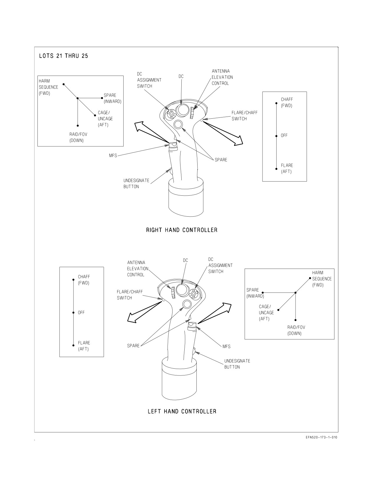
A1-F18EA-NFM-000
Figure 2-32. Hand Controllers (Sheet 1 of 2)
I-2-93
ORIGINAL
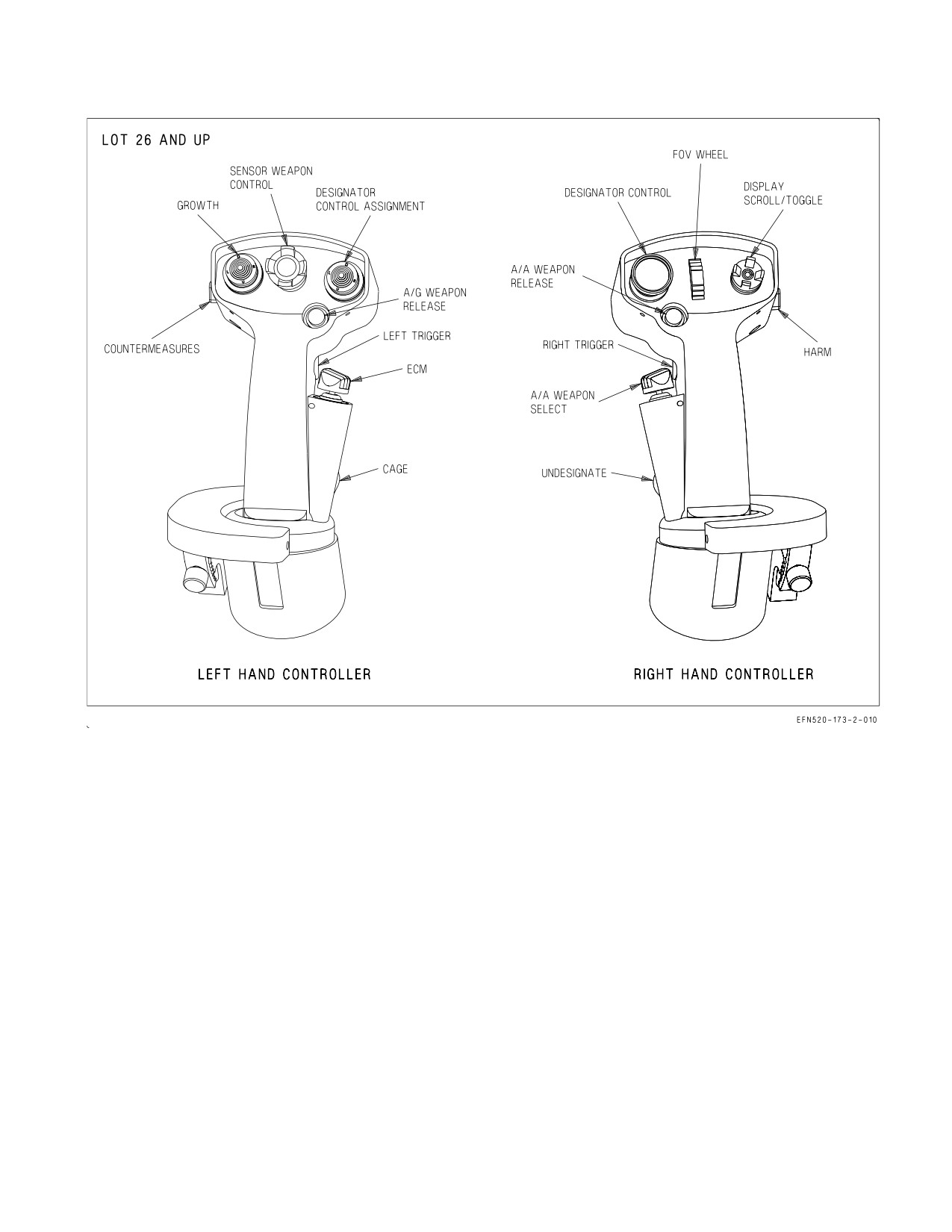
A1-F18EA-NFM-000
Figure 2-32. Hand Controllers (Sheet 2 of 2)
2.12.5.5 Chaff/Flare Dispense Switch. The chaff/flare dispense switch is located on the outboard
side of each hand controller. Dispense switch functionality differs between the left and right hand
controllers.
Left Hand Controller -
Forward
Initiates manual program 6. Dispenses chaff and flare singles (C/F mode)
Aft
Initiates manual program 6. Dispenses chaff and flare singles (C/F mode)
Right Hand Controller -
Forward
Provides semi-automatic consent. Dispenses chaff singles (C/F mode)
Aft
Initiates the selected manual program. Dispenses flare singles (C/F mode)
I-2-94
ORIGINAL
A1-F18EA-NFM-000
2.12.5.6 Undesignate Button. The undesignate button is located on the lower front of each hand
controller. The front and rear undesignate buttons are functionally identical, except the rear cockpit
buttons do not command NWS.
2.12.6 Hand Controllers (Rear Cockpit LOT 26 AND UP). The functions of the left and right hand
controllers are not identical. The left hand controller contains the following switches: Countermea-
sures, Growth, Sensor Weapons Control, Designator Control Assignment, A/G Weapon Release, Left
Trigger, ECM, and Cage. The right hand controller contains the following switches: HARM, Display
Scroll/Toggle, FOV Wheel, Designator Control, A/A Weapon Release, A/A Weapon Select, Undesig-
nate, and Right Trigger. See figure 2-32 Sheet 2. Refer to Tactical Manuals for complete Hand
controller Switch description.
2.12.7 ALE-47 DISP Switch. An ALE-47 DISP switch is located on the left canopy sill in both front
and rear cockpits. Either switch can be used to initiate manual program 6 or to dispense chaff and flare
singles (C/F mode).
2.12.8 Grab Handle Chaff/Flare Dispense Switches (Rear Cockpit LOTs 21 thru 25). The grab
handle dispense switches are located on the left and right ends of the center grab handle in the rear
cockpit. These switches provide a secondary means to dispense expendables from the ALE-47
self-protect system.
Forward
Provides semi-automatic consent. Dispenses flare singles (C/F mode)
Aft
Initiates the selected manual program. Dispenses flare singles (C/F mode)
Inboard
Initiates manual program 6. Dispenses chaff and flare singles (C/F mode)
Outboard
Initiates manual program 6. Dispenses chaff and flare singles (C/F mode)
2.12.9 Grab Handle Chaff/Flare Dispense Switches (Rear Cockpit LOT 26 and up). The grab
handle dispense switches are located on the left end of the left grab handle and the right end of the
right grab handle in the rear cockpit. Switch function is the same as described above.
2.13 ECS - ENVIRONMENTAL CONTROL SYSTEM
The environmental control system (ECS) utilizes engine bleed air to provide pressurization, heating
and cooling air to various aircraft systems. Warm air is provided for internal fuel tank pressurization
(LOT 23 and below), external fuel tank pressurization, canopy seal inflation, g-suit operation, radar
waveguide pressurization, windshield anti-ice and rain removal, gun gas purge, RECCE bay heating,
and on-board oxygen generating system (OBOGS) operation. Cold, dry conditioned air is provided for
avionics cooling. Warm and cold air are mixed to provide temperature controlled air for cabin heating,
cooling, and pressurization and windshield defog.
A liquid cooling system (LCS) is used to cool the radar transmitter. A digital ECS controller is used
to schedule ECS output, regulate system temperatures, monitor system health, and detect and isolate
faults. See foldout section for a schematic of the ECS. Items numbers, listed in ( ) next to ECS valves,
are maintenance and MSP code nomenclature.
2.13.1 Bleed Air Shutoff Valves. Engine bleed air is tapped from the final (seventh) stage of the
engine high pressure compressor. A primary bleed air pressure regulator and shutoff valve (Item 1), one
I-2-95
ORIGINAL
A1-F18EA-NFM-000
on each engine, is used to regulate bleed air output pressure as well as to control flow application/
shutoff.
Both valves are electrically controlled by the BLEED AIR knob and are pneumatically actuated.
The primary bleed air shutoff valves failsafe to the closed position if either electrical power or air
pressure is lost. If an engine is shut down before placing the BLEED AIR knob to OFF, the
corresponding primary bleed air shutoff valve may not fully close, resulting in residual engine fumes
in the cabin on subsequent start of that engine.
Bleed air from each engine passes through a check valve, which prevents reverse flow, and is mixed
through a Y-junction prior to the secondary bleed air pressure regulator and shutoff valve (Item 2).
This valve is electrically controlled by the OFF and AUG PULL positions of the BLEED AIR knob and
is pneumatically actuated. The secondary bleed air shutoff valve fails to the open (safe) position if
either electrical power or air pressure is lost.
All three valves can be automatically commanded to the closed position by the bleed air leak
detection (BALD) system.
2.13.1.1 BLEED AIR Knob. The BLEED AIR knob, located on the ECS panel on the right console, is
used to select the engine bleed air source for the ECS system.
NORM Commands both primary bleed air shutoff valves open, selecting bleed air from both
engines.
L OFF Commands the left primary bleed air shutoff valve closed, selecting bleed air from the
right engine only.
R OFF Commands the right primary bleed air shutoff valve closed, selecting bleed air from the
left engine only.
OFF Commands all three bleed air shutoff valves closed, isolating the ECS. Closes the ECS
auxiliary duct doors.
AUG Commands the secondary bleed air shutoff valve closed, opens the ECS air isolation
PULL valve, and allows APU compressor air to operate the ECS.
2.13.1.2 L or R BLD OFF Cautions. The L or R BLD OFF cautions indicate that the corresponding
primary bleed air shutoff valve(s) are commanded closed. The cautions are not an indication of actual
valve position. The L and/or R BLD OFF cautions are displayed in the following circumstances:
a. BLEED AIR knob in L OFF, R OFF, or OFF (L, R, or both cautions).
b. ENG CRANK switch in L or R (L or R caution, respectively).
c. BALD system detects a leak in one or both bleed air systems (L, R, or both cautions).
d. FIRE switch in TEST A or TEST B (both cautions).
e. Over pressurization in one or both bleed air systems (both cautions).
If a bleed air shutoff valve has been commanded closed other than by ENG CRANK, the BLEED
AIR knob must be cycled to OFF and back to NORM to reopen the valve(s).
2.13.2 Bleed Air Subsystem. Engine bleed air downstream of the secondary bleed air shutoff valve
is routed to the primary heat exchanger and three valves. The primary heat exchanger is used for first
stage cooling of hot engine bleed air. The ECS air isolation valve directs bleed air to the air turbine
I-2-96
ORIGINAL
A1-F18EA-NFM-000
starter control valves (ATSCV) for crossbleed start and accepts air from the APU compressor for
alternate (AUG PULL) ECS operation. On the ground and during slow speed flight, the ejector shutoff
valve is opened to direct bleed air to the ram air ejectors to induce cooling airflow through the primary
and secondary heat exchangers. The warm air temperature control valve is used to mix uncooled engine
bleed air with primary heat exchanger output air to regulate the temperature of air in the warm air
manifold.
2.13.3 Primary Heat Exchanger. The primary heat exchanger is located near the base of the right
vertical tail and is used to reject heat from engine bleed air to ram air from one of two inlets.
During medium to high speed flight, ram air cooling is provided by the main ram inlet which draws
air from the engine intake. During slow speed flight and ground operations, ram air cooling is provided
by an auxiliary ram inlet which draws free stream air from the top of the fuselage. A ram air ejector in
the ram air exhaust duct is used to induce more airflow when required, such as on the the ground,
during slow speed flight, and during windshield anti-ice operation with either throttle above IDLE.
2.13.3.1 ECS Auxiliary Duct Doors. Two ECS auxiliary duct doors are located on the upper surface
of the fuselage forward of the base of the vertical tails and immediately in front of the primary and
secondary heat exchangers. The ECS auxiliary duct doors are electrically actuated and open into the
free stream, closing the main ram air inlets and exposing the auxiliary ram air inlets.
On the ground, the ECS auxiliary duct doors are open with the BLEED AIR knob in any position
except OFF. Inflight, the doors are positioned based on Mach number and throttle setting. The doors
are always open below Mach 0.33 and are always closed above Mach 0.40. Between Mach 0.35 and Mach
0.40, the doors are open if either throttle is near MIL (THA greater than 25°).
The ECS auxiliary duct doors should operate symmetrically. If either ECS auxiliary duct door is not
in the commanded position for greater than 8 seconds, an ECS DR advisory is displayed along with an
ECS BIT indication of DEGD. If the door(s) return to the commanded position, the ECS DR advisory
is removed.
2.13.3.2 Ram Air Exhausts. The ECS ram air exhausts are located on the upper fuselage just aft of
the leading edge of the vertical tails. There is one exhaust for the primary heat exchanger (right side)
and one for the secondary heat exchanger (left side). These exhausts discharge the heated ram air
overboard. The exhausts have been redesigned to a five swept stack configuration to prevent
overheating of the aft fuselage structure.
2.13.4 Warm Air Subsystems. Air leaves the primary heat exchanger at a greatly reduced tempera-
ture. Warm air from the primary heat exchanger is routed directly to the following systems: internal
fuel tank pressurization (LOT 23 and below), external fuel tank pressurization, canopy seal, g-suit,
radar waveguide pressurization, and OBOGS.
The ECS controller modulates the warm air temperature control valve (Item 21) to mix air from the
primary heat exchanger with uncooled engine bleed air to regulate the temperature in the warm air
manifold. The warm air manifold supplies air for windshield anti-ice and rain removal, gun gas purge,
RECCE bay heating, ECS turbine anti-ice, and cabin heating.
2.13.5 Air Conditioning System (ACS) Pack. The ACS pack provides cold, dry conditioned air for
cabin, FLIR, and avionics cooling. The primary components of the ACS pack are a compressor, turbine,
condenser, reheater and water extractor.
I-2-97
ORIGINAL
A1-F18EA-NFM-000
The ECS controller modulates airflow through the ECS flow modulator valve (Item 4) to control
ECS flow and the speed of the ECS compressor and turbine. Compressor discharge air is directed to
the secondary heat exchanger for additional cooling. Cooled air from the secondary heat exchanger is
directed to the ECS turbine and is used as another source of OBOGS air inflight.
Expansion through the ECS turbine drives the compressor and greatly reduces the temperature of
the airflow, typically to below freezing. The ECS controller regulates the ECS turbine output
temperature and prevents ECS icing by adding warm air through the anti-ice add heat valve (Item 51).
Output temperature is regulated during low altitude operations where ECS icing would be likely.
The condenser, reheater and water extractor remove water from the cold conditioned air. With the
large heat load of the APG-79 radar, the condenser can run at sub−freezing conditions. During
prolonged operation of the APG-79 in high humidity conditions with warm fuel temperatures, periodic
automatic deicing of the condenser occurs. During de-icing, a short term increase in cabin supply air
temperature may be noticed.
In LOT 26 and up, at altitudes above 40,000 feet the water removal system may be bypassed by
opening the water extractor bypass valve (Item 171) in order to improve ECS operating efficiency. If
this valve fails to close after descending below 37,000 feet, water removal capability is degraded. Water
or ice pellets may be blown into the cabin and erratic system behavior (flow/pressure surges) may
result. An ECS ICING caution may also occur.
2.13.6 Secondary Heat Exchanger. The secondary heat exchanger is located near the base of the left
vertical tail and is used to reject heat from ECS compressor air to ram air. Operation of the secondary
heat exchanger is identical to operation of the primary heat exchanger. However, excess ECS system
moisture is sprayed onto the secondary heat exchanger to increase system cooling. This moisture may
be seen exiting the secondary heat exchanger exhaust duct when the throttles are advanced during
ground operations.
2.13.7 Avionics Cooling Fans. Two avionic cooling fans augment ECS cooling of avionics. The
avionics ground cooling fan is located in the nosewheel well. The aft avionics cooling fan is located in
door 108. These fans normally provide primary avionics cooling on deck, and also provide contingency
avionics cooling in flight. Fan activation is a function of bleed air pressure, which varies with engine N2
rpm (i.e. throttle position). Fan operation is described in the individual ECS mode descriptions.
2.13.7.1 Aft Cooling Fan Shutoff Valve. The aft cooling fan shutoff valve, when closed, secures flow
from the aft avionics cooling fan into the ECS and also prevents ECS backflow to the aft avionics
cooling fan. If this valve fails (indicated by MSP 863) while in the open position then, depending on
system pressure, ECS backflow can overspeed the fan in the wrong direction. This may cause a
structural failure of the fan and result in collateral fragment damage to adjacent systems. ECS
backflow is most likely to occur when ECS MAN mode is selected and ECS flow is commanded by
default to maximum.
I-2-98
ORIGINAL
A1-F18EA-NFM-000
Selection of ECS MAN mode is prohibited. Selecting ECS MAN mode
while the aft cooling fan shutoff valve is open may cause the fan to
overspeed, resulting in a catastrophic fan failure and potential loss of
OBOGS.
2.13.8 ECS Operating Modes. The ECS has three operating modes: AUTO, MAN (manual) (PRO-
HIBITED), and OFF/RAM. Each mode is selected by the corresponding position of the ECS MODE
switch. On the ground only, APU compressor air may be used instead of engine bleed air to run the ECS
and cool the avionics (BLEED AIR knob in AUG PULL).
2.13.8.1 ECS AUTO Mode. ECS AUTO mode is the normal operating mode of the ECS. The ECS
controller modulates ECS output to provide the required airflow to the cabin and the avionics. Cabin
airflow is scheduled as a function of ram air temperature and throttle setting, with the highest flow
delivered at hot and cold temperature extremes. Cabin flow may decrease at IDLE. ECS flow to the
avionics is dependent on WonW status, throttle setting, Lot number, and radar configuration. For all
aircraft configurations, more air is provided to avionics inflight.
With APG−73 radar installed, WonW and both throttles at IDLE, the avionics ground cooling fan
and the aft avionics cooling fan energize. With APG−79 radar installed, WonW and both throttles at
IDLE, only the avionics ground cooling fan energizes. The fan(s) provide the primary source of avionics
cooling on deck. The ECS provides a second source of ground avionics cooling but at a fixed, low flow
rate with the remainder of the flow going to the cabin.
With WonW and at least one throttle advanced to approximately 74% N2 rpm, or with WoffW, the
fan(s) secure. Once secured, the fan(s) will not reenergize until both throttles are retarded below
approximately 70% N2 rpm. With WonW and fans secured, the ECS provides all avionics cooling and
controls to the cabin and avionics airflow schedules. The ECS controller schedules avionics airflow
based on the temperature of the air being delivered (warmer air requires higher flow to maintain
constant cooling).
The ECS controller modulates airflow output to meet scheduled airflow requirements. ECS output
temperature is scheduled by the ECS controller to meet avionics cooling requirements and to prevent
ECS turbine icing. Temperature is regulated by adding warm air as required. The controller divides the
airflow between the cabin and avionics. Inflight, if ECS output is inadequate for demand, cabin airflow
is normally given priority. The avionics typically receive that portion of the ECS output which is not
used by the cabin or FLIR cooling systems.
Cabin temperature is controlled by gradually mixing warm air with cold conditioned air, according
to the position of the CABIN TEMP knob. Cabin temperature is normally selectable in the range of
35 to 135° F between the CABIN TEMP knob positions of COLD and HOT, respectively (60 to 160°
F with the DEFOG handle in the HIGH position).
NOTE
In ECS AUTO mode, cabin temperature may take 1 to 2 minutes to
stabilize following a large movement of the CABIN TEMP knob.
I-2-99
ORIGINAL
A1-F18EA-NFM-000
2.13.8.2 ECS MAN Mode.
Selection of ECS MAN mode is prohibited. Selecting ECS MAN mode
while the aft cooling fan shutoff valve is open may cause the fan to
overspeed, resulting in a catastrophic fan failure and potential loss of
OBOGS.
2.13.8.3 ECS OFF/RAM Mode. ECS OFF/RAM mode is used to terminate normal ECS operation
following a major ECS malfunction. Conditioned ECS air is terminated, the cabin ram air scoop is
deployed, and if inflight the aft avionics cooling fan energizes.
NOTE
If ECS OFF/RAM mode is selected inflight, the AV COOL switch
should be placed in EMERG to deploy the FCS emergency ram air
scoop and maximize the emergency avionics cooling available.
Partial cabin pressurization is provided, but only if the CABIN TEMP knob is above the full COLD
position. Cabin airflow and pressurization is provided by ram air from the cabin ram air scoop. Ram
air supply varies with inflight dynamic conditions (airspeed and altitude), and cabin airflow and
pressurization vary similarly.
In ECS OFF/RAM mode, avoid operations above 25,000 feet MSL in
order to prevent decompression sickness (DCS). Normal cabin pressur-
ization is not provided. Partial cabin pressurization is available under
certain circumstances, but may be lost insidiously without warning.
Inflight, cabin temperature is no longer automatically controlled. The CABIN TEMP knob
manually controls addition of heated air according to the CABIN TEMP knob. Temperature control
in between the full COLD and full HOT positions is difficult and imprecise, and ECS response to
commanded temperature changes is slow and nonlinear.
NOTE
In ECS OFF/RAM mode, changes in the position of the CABIN
TEMP knob should be held for 30 seconds due to a slower temperature
response.
With the CABIN TEMP knob not in full COLD, cabin temperature varies with throttle position and
flight condition. System flow/temperature cycling can be expected with the CABIN TEMP knob in full
HOT since overtemperature protection operates intermittently.
I-2-100
ORIGINAL
A1-F18EA-NFM-000
With WonW and both throttles at IDLE, the avionics ground cooling fan and the aft avionics cooling
fan provide the only source of avionics cooling. Above approximately 74% N2 rpm, both fans secure,
and avionics equipment is deprived of all cooling (AV AIR HOT caution).
NOTE
During ground operations in the ECS OFF/RAM mode, the throttles
should be kept below 70% N2 rpm whenever possible in order to
preserve avionics cooling. If either throttle must be advanced above
approximately 74% N2 rpm more than momentarily or if an AV AIR
HOT caution is present, placing the BLEED AIR knob to OFF
reenergizes both fans and provides avionics cooling.
Inflight, the aft avionics cooling fan and the FCS emergency ram air scoop (with AV COOL in
EMERG) provide emergency avionics cooling.
NOTE
With the FCS emergency ram air scoop extended, avionics cooling
inflight is maximized by maintaining altitude below 25,000 feet MSL
and airspeed between 200 to 300 KCAS.
2.13.8.4 AUG PULL. With both generators online and the APU running, selecting AUG PULL (up
on the BLEED AIR knob):
a. overrides APU automatic shutdown
b. closes the secondary bleed air shutoff valve.
c. opens the ECS air isolation valve.
d. shuts down the aft avionics cooling fans.
e. and directs APU air to the ECS for cabin and avionics cooling.
2.13.8.5 ECS MODE Switch. The ECS MODE switch, located on the ECS panel on the right console,
is used to select the ECS operating mode.
AUTO
Selects ECS AUTO mode, the normal ECS operating mode. Provides automatic
cabin and avionics airflow, automatic temperature scheduling, and full cabin pres-
surization.
MAN
PROHIBITED
Selection of ECS MAN mode is prohibited. Selecting ECS MAN mode
while the aft cooling fan shutoff valve is open may cause the fan to
overspeed, resulting in a catastrophic fan failure and potential loss of
OBOGS.
I-2-101
ORIGINAL
A1-F18EA-NFM-000
OFF/RAM Selects ECS OFF/RAM mode, which terminates conditioned ECS airflow. Provides
ram air for cabin airflow and pressurization depending on flight conditions, and
manual temperature control.
2.13.8.6 CABIN TEMP knob. The CABIN TEMP knob, located on the ECS panel on the right
console, is used to control the temperature of air delivered to the cabin. In ECS AUTO mode, clockwise
rotation of the CABIN TEMP knob linearly increases cabin temperature. In ECS OFF/RAM mode, the
CABIN TEMP knob controls the cabin add heat valve directly, producing a nonlinear temperature
response.
NOTE
• In ECS AUTO mode, cabin temperature may take 1 to 2 minutes to
stabilize following a large movement of the CABIN TEMP knob.
• In ECS OFF/RAM mode, changes in the position of the CABIN
TEMP knob should be held for 30 seconds due to a slower tempera-
ture response.
2.13.8.7 Cabin Louvers/Foot Air Outlet. Three sets of louvers are provided to direct airflow within
the cabin, one on either side of the main instrument panel and one at the base of the center console
behind the control stick. The left and right louvers have controls for elevation and azimuth. The center
louver has a single control for elevation and can be closed completely by moving the lever to the full
aft position. When the center louver is closed, airflow through the left and right louvers is increased.
Maximum aircrew cooling is provided by pulling the DEFOG HANDLE full aft, closing the center
louver, and directing the side louvers towards the body. A fixed foot air outlet directs airflow to the
base of the cabin.
2.13.8.8 Windshield Defog Outlets Fixed windshield defog outlets direct cabin air onto the inner
windshield to remove and inhibit fog. Windshield fogging can occur during rapid environmental
changes, such as high rates of descent and high humidity.
2.13.8.9 DEFOG Handle. The DEFOG handle, located on the right console outboard of the ECS
panel, controls the division of airflow between the windshield defog outlets, the three cockpit louvers,
and the foot air outlet. The DEFOG handle mechanically controls the position of the cabin air/defog
diverter valve.
HIGH Directs all cabin airflow to the windshield defog outlets to maximize defog, and
increases the temperature range controlled by the CABIN TEMP knob in ECS AUTO
mode.
NORM Equally divides cabin airflow between the cabin louvers/foot air outlet and the wind-
shield defog outlets. Provides adequate windshield defog for most conditions.
LOW Directs all cabin airflow to the cabin louvers and the foot air outlet to maximize cabin
cooling.
I-2-102
ORIGINAL
A1-F18EA-NFM-000
2.13.9 Cabin Pressurization. The cabin is pressurized using airflow from the cabin heating and
cooling system. Cabin pressurization is controlled by the CABIN PRESS switch and automatic
operation of the cabin pressure regulator. Cabin pressure altitude is displayed on a cabin pressure
altimeter.
Cabin pressure is controlled by the cabin pressure regulator which regulates exit airflow to maintain
a pressure/altitude schedule. The cabin is unpressurized from sea level to an aircraft altitude of 8,000
feet. Between 8,000 and 24,500 feet aircraft altitude, cabin pressure is maintained at a constant 8,000
feet. Above 24,500 feet, cabin altitude increases slowly to approximately 14,500 feet at 35,000 feet
aircraft altitude and 20,000 feet at 50,000 feet aircraft altitude. A rule of thumb for cabin altitude above
24,500 feet aircraft altitude is aircraft altitude x 0.4.
A cabin safety and dump valve is incorporated to limit cabin pressure if the pressure regulator fails.
When the CABIN PRESS switch is placed to DUMP or RAM/DUMP, the cabin safety and dump valve
opens to release pressure to the cabin pressure regulator, reducing cabin pressure to ambient.
In ECS OFF/RAM mode, avoid operations above 25,000 feet MSL in
order to prevent decompression sickness (DCS). Normal cabin pressur-
ization is not provided. Partial cabin pressurization is available under
certain circumstances, but may be lost insidiously without warning.
2.13.9.1 CABIN PRESS Switch. The CABIN PRESS switch, located on the ECS panel on the right
console, is used to control cabin pressurization. The switch is lever-locked in the NORM position.
NORM Automatically regulates cabin pressurization according to the cabin pressure schedule
using the cabin pressure regulator (ECS AUTO mode).
DUMP Dumps cabin pressurization. Normal ECS airflow to the cabin and the avionics is not
affected.
RAM/ Dumps cabin pressurization. Terminates all ECS airflow to the cabin by closing the
DUMP cabin flow valve (Item 9). Cabin airflow is provided by the cabin ram air scoop. Avion-
ics airflow is provided by a simplified control scheme.
2.13.9.2 Cabin Pressure Altimeter. A cabin pressure altimeter, located on the center console in the
front cockpit and the lower left instrument panel in the rear cockpit, displays the current cabin
pressure altitude.
2.13.9.3 Cabin Pressurization Warning System (CPWS). The CPWS pressure switch monitors cabin
pressure and aircraft relays monitor related controls to warn aircrew of potentially hazardous cabin
pressurization conditions.
2.13.9.3.1 CABIN Caution Light. The yellow CABIN caution light is located on the lower right
caution lights panel. The light illuminates when cabin pressure altitude is above 21,000 +/- 1,100 feet.
The light may not extinguish until cabin pressure altitude is below 16,500 feet.
I-2-103
ORIGINAL
A1-F18EA-NFM-000
• CABIN light may appear with normal cabin pressurization when
aircraft altitude is above 47,000 feet MSL. If altitude is maintained,
aircrew should continuously monitor physiological condition.
• DCS may be experienced when operating with cabin pressure altitude
above 25,000 feet even with a working oxygen system. Symptoms of
DCS include pain in joints, tingling sensations, dizziness, paralysis,
choking, and/or loss of consciousness.
NOTE
There is no corresponding DDI caution for the CABIN caution light.
2.13.9.3.2 CK ECS Caution Light. The yellow CK ECS caution light is located on the lower right
caution lights panel. The light illuminates when the position of cabin pressurization related controls
will inhibit cabin pressurization.
NOTE
There is no corresponding DDI caution for the CK ECS caution light.
2.13.10 Windshield Anti-ice and Rain Removal. The windshield anti-ice and rain removal systems
use the same air nozzle to direct warm air over the external windshield in order to improve pilot
forward visibility in icing/raining conditions. Warm air is provided by mixing engine bleed air with
output from the primary heat exchanger. Windshield air nozzle orientation is intended to affect (in
flight) an area roughly 20 inches to the left and 9 inches to the right of centerline at design eye level
and below. System operation is controlled by the WINDSHIELD switch.
2.13.10.1 WINDSHIELD Switch. The WINDSHIELD switch, located on the right console outboard of
the ECS panel, is used to select either windshield anti-ice or rain removal. The switch is lever-locked
to the OFF position.
ANTI Delivers a high flow rate of 290 ±20°F air to the external surface of the windshield.
ICE
OFF Terminates anti-ice/rain removal airflow.
RAIN Delivers a low flow rate of 270 ±20°F air to the external surface of the windshield.
2.13.11 Anti-g System. The anti-g system delivers air pressure to the g-suit proportional to sensed
load factor. A button in the anti-g valve allows the aircrew to test system operation by manually
inflating the anti-g suit. The system incorporates a pressure relief valve to prevent over-pressurization.
I-2-104
ORIGINAL
A1-F18EA-NFM-000
2.13.12 ECS RESET and AV COOL Switch.
2.13.12.1 ECS RESET. If the ECS is DEGD, selecting the ECS RESET option from the BIT/
HYDRO-MECH display commands an ECS controller software reset and may restore normal
functionality following a transient fault.
Resetting the ECS controller at mid to high power settings may cause
uncomfortable cabin pressure surges and ear pain.
Resetting the ECS controller results in the loss of system over-
temperature protection for 10 to 70 seconds.
2.13.12.2 AV COOL Switch. The AV COOL switch, located on the lower right instrument panel,
extends the spring−loaded FCS ram air scoop located on the right side of the forward fuselage for
emergency cooling of FCC A, the right TR, and one AHRS unit. The AV COOL switch should be placed
in EMERG if an FCS HOT caution is displayed or during ECS OFF/RAM mode operation as a
preventative measure. Once extended, the FCS emergency ram air scoop cannot be retracted in flight.
EMERG Extends the FCS emergency ram air scoop to provide direct ram air cooling of FCC A,
the right TR, and one AHRS unit, and supplemental cooling to other avionics.
NORM FCS emergency ram air scoop not extended. The switch is spring−loaded to the NORM
position.
2.13.13 LCS - Liquid Cooling System. The LCS is a closed loop system normally used to transfer
heat from the radar transmitter to fuel and/or ambient air. When fuel temperatures are warmer than
the liquid coolant (typically at low fuel levels and high ambient temperatures), the LCS is used to
transfer heat from the fuel to ambient air. The LCS contains a liquid coolant pump, a liquid coolant/air
heat exchanger, and an LCS ground cooling fan (all three located in the left LEX) and two liquid
coolant/fuel heat exchangers, and in LOT 26 and up, two liquid coolant/ECS air heat exchangers.
The LEX liquid coolant/air heat exchanger has one air inlet located on the bottom of the LEX, and
two air exhausts. Only one exhaust path is commanded open at any given time. During LCS ground
cooling fan operation, the exhaust on the bottom of the LEX is commanded open. Inflight, only the air
exhaust on the top of the LEX can be commanded open.
LCS ground cooling fan air is the primary cooling source for liquid coolant on deck. During ground
operations, the liquid coolant pump and LCS ground cooling fan are commanded on when power is
applied to the radar (RADAR knob in STBY, OPR, or EMERG).
During ground operations, when feed tank fuel temperatures exceed 40°C (30°C in LOT 26 and up),
the liquid coolant pump and LCS ground cooling fan may also be commanded on if the RADAR knob
in OFF in order to provide LCS cooling of the fuel system. In LOT 25 and below, the bypass valve,
which allows liquid coolant to the liquid coolant /fuel heat exchangers, is solely controlled by the liquid
coolant temperature, so the amount of fuel cooling provided (if any) depends on the temperature of
I-2-105
ORIGINAL
A1-F18EA-NFM-000
each fluid. In LOT 26 and up, the bypass valve is controlled by the ECS controller and will only allow
liquid coolant to the liquid coolant/fuel heat exchanger with the RADAR knob in OFF.
NOTE
In LOT 26 and up, the RADAR knob must be in OFF in order to
provide any postflight LCS fuel cooling.
In either case, placing the RADAR knob to OFF removes the radar as a heat source and should
extend ground operating time.
Inflight, the LCS ground cooling fan secures, the lower air exhaust path closes, and the upper air
exhaust path is controlled by the mission computer. The upper air exhaust path opens when feed tank
fuel temperatures exceed 40°C (30°C in LOT 26 and up), ram air is cooler than fuel, and AOA is below
15°C. In LOT 25 and below, heat not removed by the LEX liquid coolant/air heat exchanger is removed
by the fuel system through the liquid coolant/fuel heat exchangers. In LOT 26 and up, heat not
removed by the LEX liquid coolant/air heat exchanger is removed by a combination of the liquid
coolant/fuel and liquid coolant/ECS air heat exchangers.
In LOT 26 and up, provisions have been incorporated to limit the risk of fire following a major liquid
coolant leak. When LCS low pressure is detected, the liquid coolant pump secures and check valves
limit coolant leakage. Since the SDC controls the liquid coolant pump, an SDC reset secures the pump,
resulting in a radar OVRHT (APG−73) or LOFLOW (APG−79) indication, and the radar stops
transmitting.
NOTE
In LOT 26 and up, an SDC reset temporarily secures the liquid coolant
pump. Before selecting SDC RESET, the RADAR knob should be set
to STBY until the SDC reset is complete and normal radar cooling
capability is restored.
2.13.14 ECS Related Warnings, Cautions, and Advisories. The following ECS related warnings,
cautions, and advisories are described in the Warning/Caution/Advisory Displays in Part V:
D L BLEED and R BLEED warning lights
D FCS HOT caution
D BLEED AIR LEFT (RIGHT) voice alert
D FLIR OVRHT caution
D AV AIR HOT caution
D GUN GAS caution
D L or R BLD OFF cautions
D TK PRES LO caution
D CABIN caution light
D TK PRES HI caution
D CK ECS caution light
D WDSHLD HOT caution
D ECS ICING caution
D ECSDR advisory
D EXT TANK caution
If ECS troubleshooting has been done while on deck, check for an 8A6
MSP code after takeoff. An 8A6 MSP code is set by a system flow
modulating regulating valve failure. This failure can potentially lead to
an unexpected loss of cabin pressurization.
I-2-106
ORIGINAL