EA-18G. FLIGHT MANUAL (2008) - page 8
A1-E18GA-NFM-000
DDI Cautions and Caution Lights
INDICATOR
• CAUSE / REMARKS
CORRECTIVE ACTION
• Either wing indicates unlocked (beer can up).
• Catapult with the WINGFOLD switch in FOLD
or HOLD.
• An electrical failure in the WING UNLK caution
circuitry.
The wings cannot be unlocked or folded in flight,
even if the WINGFOLD switch is placed to FOLD
or HOLD. If a WING UNLK caution appears with
IN FLIGHT
the beer cans down, an electrical failure has
1. WINGFOLD switch - VERIFY SPREAD
occurred in the caution circuitry and not in the
2. Wingfold unlock flag (Beer Cans) - CHECK
wing unlock circuitry. If the WINGFOLD switch is
DOWN
inadvertently placed to HOLD or FOLD in flight,
the wings unlock and the ailerons fair when the
If wings inadvertently unlocked/folded on
aircraft transitions to WonW during landing. In
catapult shot -
FOLD, the wings fold when the aircraft decelerates
1. Do not change WINGFOLD switch position.
below 66 KCAS during landing rollout.
2. Climb to a safe altitude.
3. WINGFOLD switch - SPREAD
WING UNLK
If the wings are partially folded -
4. Unload the aircraft to reduce aerodynamic
forces.
Ensure the WINGFOLD switch is lever-locked in
the SPREAD position during takeoff checks. If the
FOR LANDING
wings are commanded to unlock or fold during a
If both beer cans down -
catapult shot, the wings unlock, the ailerons fair,
5. Make a normal landing.
the wings may fold partially, and the aircraft will
If both beer cans are up -
settle.
5. Make an arrested landing (if practical).
6. Make sure NWS HI not engaged.
If the wings are unlocked during landing rollout,
ensure the NWS button is not pressed and full-time
NWS HI is not engaged. In NWS HI, rudder pedal
inputs command significantly greater nosewheel
deflections and may result in a loss of directional
control.
Figure 12-1. Warning/Caution/Advisory Displays (Sheet 33 of 63)
V-12-35
ORIGINAL
A1-E18GA-NFM-000
FCES CAUTIONS
INDICATOR
• CAUSE / REMARKS
CORRECTIVE ACTION
INITIAL FCS/FCES CAUTION
PROCEDURES
1. Cease maneuvering.
• An FCS/FCES related failure has occurred.
2. FCS page - SELECT and identify failure
If AOA Xd in all four channels -
FCS page Xs and/or BLIN codes identify the
3. Execute AOA Four Channel Failure procedure
location and type of failure. For certain FCS
All other failures -
components, BLIN codes may be the only
3. FCS RESET button - PUSH
indication of a failure and should be treated with
If no reset and no more than single X in any
the same initial level of concern as failures that also
row −
produce Xs. An FCS RESET attempt clears the
4. Land as soon as practical.
FCS caution whether or not the reset was
If no reset and two or more Xs in any row -
FCS
successful. A successful reset is indicated by the
4. The following general restrictions apply:
Initial
RSET advisory and removal of all Xs from the FCS
• AOA below 10° in flaps AUTO, on-speed in
page. The RSET advisory is displayed if a reset
flaps HALF/FULL
attempt was unsuccessful.
• 2g maximum
• Minimum sideslip
• Half lateral stick maximum
5. Refer to the appropriate failure procedure:
• AHRS 1/2 Channel Failure
FCS page Xs indicate the respective FCS function
• AHRS Four Channel Failure
FCS
has been shutdown. The FCS RESET button does
• Aileron Failure
not fix a detected failure, but merely allows the
• AOA Four Channel Failure
FCES
components to be restored and failure indications to
• P/R/Y CAS
Caution Light
be removed if the failure no longer exists. Avoid
• FCS Single Channel Failure
multiple FCS reset attempts of a recurring FCS
• FC AIR DAT
″Flight Controls,
failure to preclude the failure from occurring during
• FCES Caution Light
Flight Controls″
a critical phase of flight (e.g., during final approach
• FLAPS OFF-LEF Failure
to landing).
• FLAPS OFF-TEF Failure
• FLAP SCHED
No single electrical failure (e.g., single channel)
• Rudder Failure
affects flying qualities. The FCS has multiple layers
• Stab Failure
of redundancy and is designed to fail to the least
If no procedure applies -
critical configuration. No electrical or mechanical
6. Execute Controllability Check procedure (if
backup mode is provided for normal CAS functions.
required).
Multiple FCS failures are required before flying
7. Fly a straight-in approach (if practical).
qualities are degraded.
8. Land as soon as practical.
Figure 12-1. Warning/Caution/Advisory Displays (Sheet 34 of 63)
V-12-36
ORIGINAL
A1-E18GA-NFM-000
FCES CAUTIONS
INDICATOR
• CAUSE / REMARKS
CORRECTIVE ACTION
AHRS ONE OR TWO CHANNEL FAILURE
• FCCs have detected a failure of AHRS rate or
acceleration data in one or two channels.
For each failed channel, rate sensor failures will
occur in all three sensor axes (Xs in CAS P, CAS R,
AHRS
and CAS Y) and acceleration sensor failures will
When FCS/FCES Initial procedures
One or Two
occur in both sensor axes (Xs in N ACC and L
complete -
Channel Failure
ACC) simultaneously.
One channel AHRS failure -
Loss of one or two AHRS channels will not affect
6. Land as soon as practical.
flying qualities.
FCS
Two channel AHRS failure -
Loss of redundancy in rate and acceleration
6. Descend below 25,000 feet.
information to the FCCs is the primary concern for
If degradation in flying qualities is
FCES
a two channel failure. Although there is no
present -
degradation in flying qualities, subsequent AHRS
7. Refer to AHRS Four Channel Failure
Caution Light
failures could lead to controllability problems if the
procedures.
two channel AHRS failure procedures are not
If no degradation in flying qualities is
Five Xs will appear for
followed.
each failed channel
present -
(CAS P, CAS R, CAS Y,
7. Land as soon as practical.
N ACC, and L ACC)
It is possible that a third AHRS channel has failed
but is not detected. Flying qualities will be
degraded for this situation and will include poor
roll coordination for large lateral inputs, pitch
coupling, and sluggish pitch response. If flying
qualities are degraded, assume a four channel
failure has occurred, and refer to AHRS Four
Channel Failure.
Figure 12-1. Warning/Caution/Advisory Displays (Sheet 35 of 63)
V-12-37
ORIGINAL
A1-E18GA-NFM-000
FCES CAUTIONS
INDICATOR
• CAUSE / REMARKS
CORRECTIVE ACTION
AHRS FOUR CHANNEL FAILURE
• FCCs have detected a failure of AHRS rate or
acceleration data in three or four channels.
For each failed channel, rate sensor failures will
occur in all three sensor axes (Xs in CAS P, CAS R,
AHRS
and CAS Y) and acceleration sensor failures will
Four Channel
occur in both sensor axes (Xs in N ACC and L
Failure
ACC) simultaneously.
When FCS/FCES Initial procedures
PCAS
It is possible to experience a three channel failure
complete -
RCAS
with only two channels Xd out. Flying qualities will
6. FLAP switch - AUTO
YCAS
be degraded for this situation.
7. If above 25,000 feet, maintain >0.92 Mach until
FCS
descent below 25,000 feet is accomplished.
A detected loss of a third AHRS channel will result
8. Jettison unwanted stores, if required, to
FCES
in all four AHRS channels being Xd out. Three
improve flying qualities.
columns of Xs will not be displayed because the
9. Execute a straight-in on-speed approach with
Caution Light
FCCs cannot determine the good channel.
flaps in AUTO. Limit angle of bank to 20°.
10. If not positioned for landing by in-the-middle
Below 20,000 feet, flying qualities are best between
to in-close, a wave off and go around should be
″Flight Controls,
190-210 KCAS. Pitch and directional damping will
executed.
Flight Controls″
be very low and roll coordination will be weak.
11. Make an arrested landing if available.
12. Avoid stabilator braking.
Five Xs will appear for
each failed channel
(CAS P, CAS R, CAS Y,
N ACC, and L ACC).
• With a four channel AHRS failure, the aircraft is
not controllable with the flaps in HALF or FULL.
At altitudes above 25,000 feet, loss of control will
occur below 0.92 Mach. For loss of AHRS above
25,000 feet, maintain airspeed above 0.92 Mach
while descending.
• Potential for lateral pilot induced oscillations
(PIO) exists when landing with a Y CAS failure.
AILERON ACTUATOR FAILURE
• Aileron failures may be caused by an actuator
failure (mechanical or two channel failure) or by
Aileron Failure
a switching valve failing to switch to the backup
circuit following a HYD circuit failure.
When FCS/FCES procedures complete -
Speedbrake function and autopilot inoperative.
FCS
6. Execute Controllability Check procedure.
Following an aileron actuator failure, the surface is
driven to a faired position by air loads and is
FCES
For landing -
damped to prevent oscillations. If the ailerons were
7. FLAP switch - HALF or FULL
drooped, the opposite aileron is driven to the
Caution Light
8. Fly a straight-in approach (if practical).
undrooped position. With both ailerons undrooped,
9. Fly on-speed AOA to touchdown.
approach speed will increase by about 11 knots in
Flaps FULL and 17 knots in Flaps HALF. The
″Flight Controls,
operating aileron continues to provide roll control.
Flight Controls″
Roll damping is noticeably less. Use care to prevent
overcontrol and resulting lateral PIO, especially
when approaching touchdown.
Figure 12-1. Warning/Caution/Advisory Displays (Sheet 36 of 63)
V-12-38
ORIGINAL
A1-E18GA-NFM-000
FCES CAUTIONS
INDICATOR
• CAUSE / REMARKS
CORRECTIVE ACTION
• FCCs have detected an excessive split between
the left and right AOA probes immediately after
takeoff.
IMMEDIATELY AFTER TAKEOFF
1. Throttles - MIL (MAX if required)
The AOA caution can only be activated within 12
2. Fly straight ahead.
seconds after WoffW. After 12 seconds, the caution
3. Maintain 10° to 12° pitch attitude with the
is removed, even if the failure remains. If the failure
waterline symbol.
AOA
remains, an FCS caution is set along with Xs in all
When safely airborne -
four AOA channels. With the AOA caution set, the
4. FCS page - SELECT
FCES
FCCs utilize a fixed gain (on-speed AOA) for pitch
If FCS caution set and AOA Xd in all four
axis control, so expected flying qualities during the
channels -
Caution Light
first 12 seconds should be fairly nominal. With the
5. Execute the AOA Four Channel Failure
caution set, movement of the FLAP switch does not
procedure.
″Flight Controls,
change flap scheduling (e.g., flaps stay down). The
If no AOA Xs present -
Flight Controls″
AOA value displayed in the HUD is the average of
5. Continue mission Split was transitory but in-
the two split AOA probes.
dicative of a binding-probe condition. Monitor
AOA for proper indications.
For landing -
6. Execute the AOA Four Channel Failure proce-
With an AOA caution set, HUD displayed AOA
dure.
may be grossly in error and should not be utilized
to control aircraft flyaway.
Figure 12-1. Warning/Caution/Advisory Displays (Sheet 37 of 63)
V-12-39
ORIGINAL
A1-E18GA-NFM-000
FCES CAUTIONS
INDICATOR
• CAUSE / REMARKS
CORRECTIVE ACTION
AOA FOUR CHANNEL FAILURE
• A persistent (> 10 second) mismatch between the
left and right AOA probes has been detected
(15° in flaps AUTO or 5.5° to 15° in flaps
HALF/FULL depending on sideslip). Mismatch
may be caused by a transient condition; a stuck,
binding, or damaged probe; or a two-channel
When FCS/FCES Initial procedures
probe failure.
complete -
4. The following general restrictions apply:
Autopilot inoperative.
• AOA below 10° in flaps AUTO, on-speed in
flaps HALF/FULL
If the detected probe split clears in flaps AUTO,
• 2g maximum
the four channel AOA Xs and the FCS caution are
• minimum sideslip
automatically removed. In flaps HALF/FULL, an
• Half lateral stick maximum
FCS RESET is required to clear the failure
For landing -
indications if the split was transitory. With a four
5. Slow below 180 KCAS at a safe altitude.
channel AOA failure, AOA indications are removed
6. LDG GEAR handle - DN
from the HUD. HUD displayed AOA can be
7. FLAP switch − HALF or FULL
AOA Four Channel
restored by selecting (boxing) the valid AOA probe
8. GAIN switch - ORIDE (ATC is not
Failure
on the FCS page with GAIN ORIDE selected. In
available in GAIN ORIDE.)
flaps AUTO, the FCCs utilize the AOA estimator
9. FCS page − SELECT
for gain scheduling. In flaps HALF/FULL, rudder
10. If possible, identify undamaged probe using
toe-in is disabled, and the FCCs use a fixed 8.1°
center (INS) AOA value, airspeed cross-check
AOA gain for longitudinal control and the estimator
or wingman.
for lateral-directional control. In flaps AUTO, flying
If undamaged probe identified -
FCS
qualities with gains scheduled by the AOA
11. Undamaged probe - SELECT (press
estimator should be essentially normal compared to
AOA pushbutton on DDI as needed)
FCES
the fixed gains used in GAIN ORIDE.
12. Fly a straight-in approach (if practical).
13. Notify LSO that GAIN ORIDE and a
Caution Light
single probe has been selected.
14. Fly on−speed AOA to touchdown.
″Flight Controls,
15. Maintenance action required prior to
Flight Controls″
• If an AOA probe is stuck or damaged (IFR
next flight.
basket impact, bird strikes, probe icing), AOA
If undamaged probe NOT identified -
errors may be unannunciated if the AOA split
11. Fly a straight-in approach (if practical).
thresholds are not exceeded.
12. Determine on-speed for intended
• Bolters in GAIN ORIDE or with AOA failed
landing GW.
require positive aft stick during rotation, ≥ 1/2
13. If on-speed AOA and airspeed do not
stick is recommended. Deflection of less than 1/2
cross-check, fly airspeed to touchdown.
aft stick will result in excess settle during bolters.
14. Notify LSO that GAIN ORIDE has been
selected and AOA indications may be in
error.
15. Maintenance action required prior to
next flight.
In GAIN ORIDE, AOA will tend to readily increase
above 14° when decelerating from a trimmed on-
speed condition. Timely longitudinal stick inputs
will be required to prevent excessive sink rates and
correct a deceleration as power alone will not change
the AOA or pitch attitude sufficiently in GAIN
ORIDE. Alpha tone is disabled in GAIN ORIDE
with flaps HALF/FULL.
Figure 12-1. Warning/Caution/Advisory Displays (Sheet 38 of 63)
V-12-40
ORIGINAL W/IC1
A1-E18GA-NFM-000
FCES CAUTIONS
INDICATOR
• CAUSE / REMARKS
CORRECTIVE ACTION
• Auto throttle control (ATC) failed.
• GAIN ORIDE selected with ATC approach mode
ATC FAIL
1. Control throttles manually.
engaged.
2. Avoid flight above 700 KCAS or 1.8 Mach.
• Bank angle >70° in HALF or FULL flaps.
FCES
If GAIN ORIDE selected with ATC
approach mode engaged -
ATC capability not available. Supersonic engine
Caution Light
1. FCS RESET button - PUSH
thrust limiting (SETLIM) and ABLIM may be
disabled.
P CAS
or
R CAS
or
• FCS degraded in its ability to measure rates or
Y CAS
acceleration in either pitch (P), roll (R), or yaw
(Y) axis, as indicated.
Refer to AHRS Four Channel Failure proce-
FCS
dures.
FCES
Potential for lateral PIO exists when landing with a
Caution Light
Y CAS failure.
″Flight Controls,
Flight Controls″
FCS SINGLE CHANNEL FAILURE
• FCC channel failure.
No change in flying qualities.
Speedbrake function inoperative.
FCS Single
Channel 2 or Channel 4:
Channel Failure
• ATC inoperative.
When FCS/FCES Initial procedures
• Normal NWS inoperative.
complete -
Channel 2 also:
6. Circuit breaker failed channel - PULL, pause
• Loss of HUD baro altitude and IFF reporting
20 seconds, RESET
FCS
(standby altitude and RALT still available).
7. Land as soon as practical.
• MAD sensor data lost. (Mag heading may
With CH 2 or CH 4 failed -
FCES
degrade).
8. Consider a precautionary arrested landing (if
available). (Normal NWS is not available.)
Channel 4 also:
Caution Light
• AOA indexer/approach lights inoperative.
Pulling the wrong circuit breaker shuts down a
second flight control channel and may result in
degraded flying qualities or loss of control.
Figure 12-1. Warning/Caution/Advisory Displays (Sheet 39 of 63)
V-12-41
ORIGINAL
A1-E18GA-NFM-000
FCES CAUTIONS
INDICATOR
• CAUSE / REMARKS
CORRECTIVE ACTION
• Left and right pitot-static probes are reporting in the valid range
but disagree.
• Pitot−static failure (both pitot probes invalid, PTS inoperable or
an excessive split between left and right readings).
Caution is also accompanied by four channel PTS X−out.
FCCs use the highest total pressure input.
If the FC AIR DAT caution resulted from a loss of air data, the
Wheels Warning is also set. With a loss of static pressure, HUD
displayed altitude and vertical velocity are blanked. With a loss of
total pressure, HUD displayed Mach and airspeed are blanked, but
altitude appears with an X to the right (e.g., value is uncorrected).
With the GAIN switch in ORIDE, the FCCs use fixed values for
When FCS/FCES Initial procedures
speed, altitude, and AOA depending on FLAP switch position. These
complete - Assess indications.
fixed gains cause the LEFs, TEFs, and AIL droop to be driven to
If HUD airspeed and standby air-
fixed positions.
speed indicators agree -
Flaps
Mach KTAS Feet
°AOA
6. Airspeed - Maintain below 350 KCAS
AUTO
0.80
459
39,000
3.5
HALF
0.23
151
500
8.1
If airspeed blanked or does not
FULL
0.21
139
500
8.1
agree with standby indicator -
6. Establish 4° to 5° AOA (DO NOT EX-
When ORIDE selected, the FLAPS light comes on along with the
CEED 10° AOA).
CRUIS advisory (flaps AUTO) or the LAND advisory (flaps HALF
or FULL). Noticeable transients may occur when selecting GAIN
FC AIR DAT
In all cases, from wings-level flight
ORIDE. Longitudinal and lateral response is more sluggish as
Once below 350 KCAS/above 4°
airspeed is reduced below the gain values and is more sensitive as
FCS
AOA -
airspeed is increased above the gain values. Do not lower the flaps in
7. GAIN switch - ORIDE
a turn as higher than normal aft stick forces are required and
sideslip excursions may occur due to fixed gains logic. Avoid
FCES
For landing -
over−control and resulting PIO during flap transition.
8. Airspeed - Below 180 KCAS (approxi-
Caution Light
mately 6° to 7° AOA)
In wings-level flight -
D With an FC AIR DAT caution, HUD displayed airspeed may be in
9. LDG GEAR handle - DN
error. Fly an on-speed AOA approach (GAIN ORIDE selected).
10. FLAP switch - HALF or FULL
D Bolters in GAIN ORIDE or with AOA failed require positive aft
11. DO NOT EXCEED 190 KCAS or 10°
stick during rotation, ≥1/2 stick is recommended. Deflection of less
AOA.
than 1/2 aft stick will result in excess settle during bolters.
12. Fly a straight-in approach (if practi-
D AOA warning tone is disabled in GAIN ORIDE with flaps
cal).
HALF/FULL.
13. Fly on-speed AOA to touchdown.
(ATC is not available in GAIN
ORIDE.)
D In GAIN ORIDE, AOA will tend to readily increase above 14°
when decelerating from a trimmed on-speed condition. Timely
longitudinal stick inputs will be required to prevent excessive
sink rates and correct a deceleration as power alone will not
change the AOA or pitch attitude sufficiently in GAIN ORIDE.
D If left pitot probe is damaged or suspect, standby instruments
including standby airspeed indicator may be significantly erroneous.
In all cases where airspeed are suspect, reference AOA values to
approximate airspeed for selection of GAIN ORIDE, landing
configuration, and approach to landing.
Figure 12-1. Warning/Caution/Advisory Displays (Sheet 40 of 63)
V-12-42
ORIGINAL W/IC1
A1-E18GA-NFM-000
FCES CAUTIONS
INDICATOR
• CAUSE / REMARKS
CORRECTIVE ACTION
When FCS/FCES Initial procedures
complete -
6. Airspeed - Maintain below 250 KCAS
7. Attempt to identify the malfunction.
8. Execute Controllability Check procedure.
• If MC1 is inoperative, the FCES caution light is
the only indication of a FCES failure.
If failure not identified and DDI warnings
FCES
and FCS cautions still inoperative -
The FCS page is not available.
Caution Light
For landing -
If the FCES light remains on after an FCS RESET
9. Slow below 180 KCAS at a safe altitude.
(With MC1
attempt, an actuator is still failed or one of the
10. LDG GEAR handle - DN
Inoperative)
following cautions did not reset: AOA, ATC FAIL;
11. FLAP switch - HALF or FULL
P, R or Y CAS; FC AIR DAT, FCS, FLAP SCHED,
12. GAIN switch - ORIDE (if required)
FLAPS OFF, HYD 5000, or NWS.
13. FCS page - SELECT VALID AOA PROBE (if
required)
14. Fly a straight-in approach (if practical).
15. Fly on-speed AOA to touchdown. (ATC is not
available in GAIN ORIDE.)
16. Make a precautionary short field arrestment (if
required).
• FCC A over-temperature detected.
• AHRS over-temperature detected.
FCS HOT
The FCCs can only operate for a short time without
FCS HOT
cooling. Placing the AV COOL switch to EMERG
1. Maintain airspeed below 325 KCAS (300 to 325
provides emergency ram air cooling to FCC A and
KCAS optimum for cooling).
Caution Light
the right TR through a dedicated ram air scoop. If
2. AV COOL switch - EMERG
circumstances require airspeed above 325 KCAS,
3. Land as soon as possible.
delay deploying the FCS ram air scoop, as ram air
″Flight Computer Hot,
temperature may actually increase FCC heating and
Flight Computer Hot″
decrease operating time. Once deployed, the FCS
ram air scoop cannot be closed in flight.
Figure 12-1. Warning/Caution/Advisory Displays (Sheet 41 of 63)
V-12-43
ORIGINAL
A1-E18GA-NFM-000
FCES CAUTIONS
INDICATOR
• CAUSE / REMARKS
CORRECTIVE ACTION
LEF FAILURE
• LEF failures may be caused by an actuator failure (mechanical or two channel
failure) or by a switching valve failing to switch to the backup circuit following
a HYD circuit failure.
Speedbrake function and autopilot inoperative.
LEF actuators continue to operate following single channel failures. If a LEF
actuator is shutdown, the failed surface is mechanically locked in its current
position. The opposite LEF is held frozen by the FCCs except for differential
control in flaps AUTO. In most cases, the LEFs should be fairly symmetric;
however, multiple FCS reset attempts may aggravate the asymmetry.
Additionally, in flaps AUTO, aileron droop is set to zero, and TEFs are also held
fixed in their current position. However, in flaps HALF/FULL, TEFs and aileron
droop follow the normal schedules based on FLAP switch position. With a LEF
locked near 21° LED (±5°), flaps HALF/FULL handling qualities are essentially
normal. If locked above this position, stall margin is reduced. For LEFs locked
near 0° LED (±5°), light to moderate buffet levels persist for AOAs above
on-speed. The buffet is more pronounced with LEF deflections significantly less
When FCS/FCES Initial
than the normal scheduled positions. Selecting flaps FULL with the LEF at or
near 0° results in higher buffet levels at lower AOAs than with the FLAP switch
procedures complete -
set to HALF. Selecting flaps FULL is not recommended.
LEF
Small (1-3°) roll oscillations due to buffet can be expected but are easily
If failed in flaps HALF/
Failure
controllable with small lateral inputs. Roll and line-up control are not
FULL and flaps AUTO re-
significantly different than with normal scheduled positions. The aircraft rolls
faster into the lesser-deflected LEF and slower when rolling away from the
quired -
lesser-deflected LEF. Roll-off may also be experienced with AOA/pitch attitude
6. Airspeed - 180 KCAS
changes. As AOA decreases, the aircraft rolls away from the lesser-deflected LEF
7. LDG GEAR handle - UP
and as AOA increases, the aircraft rolls into the lesser-deflected LEF. Lateral
8. FLAP switch - AUTO
stick and/or trim easily counters this roll-off tendency. A small roll-off will occur
with airspeed changes during a waveoff or bolter but are easily controlled with
9. GAIN switch - ORIDE
small lateral stick inputs.
When TEFs retract to 4°
FLAPS OFF
Glideslope control degradations are more pronounced with LEF deflections
TED -
significantly less than the normal scheduled positions. The addition of wing stores
10. GAIN switch - NORM
FCES
will further degrade glideslope control as a result of additional drag. The aircraft
response to power corrections is sluggish and smaller in magnitude than normal
flap configurations. Larger, longer, and more anticipatory power corrections are
For landing -
Caution Light
required to effect a glideslope change. Power corrections translate to an airspeed
11. Execute Flaps-HALF Con-
change first before a rate of descent change is noticed. The delay in aircraft
trollability Check proce-
response coupled with the larger throttle inputs leads to the tendency to over
dure, including throttle re-
control the glideslope. The technique of applying power and waiting for a
glideslope change will lead to larger glideslope deviations. Anticipatory throttle
sponse and waveoff
FLAPS
inputs are key to controlling glideslope. The sluggish power response also
maneuver.
degrades waveoff performance. When operating shipboard, the waveoff window for
12. FLAP switch - HALF
Amber
all LEF failure conditions should be moved farther out and the LSOs should be
13. Fly a straight-in approach
made aware of the degraded glideslope performance. Upon bolter/waveoff, climb-
out attitude will appear flatter than normal. The LSOs and PRIFLY personnel
(if practical).
should monitor rate of climb as the primary indication of bolter/waveoff
14. Field - If buffet level is
performance. It is recommended aircrew perform a familiarization check of
uncomfortable on-speed, fly
″Flight Con-
aircraft response to control and throttle inputs, including a waveoff maneuver,
a slightly fast approach (6°
trols,
prior to attempting a shipboard landing.
to 7° AOA) then slow to
Flight Con-
If AUTO is selected after HALF or FULL, the TEFs only retract for loads
alleviation (no higher than approximately 17° TED at flap auto retract). If fuel or
on-speed AOA prior to
trols″
range is a concern, momentary selection of GAIN ORIDE brings the TEFs up to
touchdown.
4° TED and then returns them to normal scheduling. GAIN ORIDE also
Carrier - Fly on-speed
commands the operating LEF to 5° LED for the remainder of the flight. If the
throughout approach.
LEFs were previously fixed at a more LED position, GAIN ORIDE may drive a
controllable but undesirable LEF split. Therefore, only select GAIN ORIDE if
TEF retraction is essential or if the LEFs are fixed near 5° LED.
Bolters in GAIN ORIDE or with AOA failed require positive aft stick during
rotation, ≥1/2 stick is recommended. Deflection of less than 1/2 aft stick will
result in excess settle during bolters.
In GAIN ORIDE, AOA will tend to readily increase above 14° when decelerating
from a trimmed on-speed condition. Timely longitudinal stick inputs will be
required to prevent excessive sink rates and correct a deceleration as power alone
will not change the AOA or pitch attitude sufficiently in GAIN ORIDE. Alpha
tone is disabled in GAIN ORIDE with flaps HALF/FULL.
Figure 12-1. Warning/Caution/Advisory Displays (Sheet 42 of 63)
V-12-44
ORIGINAL W/IC1
A1-E18GA-NFM-000
FCES CAUTIONS
INDICATOR
• CAUSE / REMARKS
CORRECTIVE ACTION
TEF FAILURE
• TEF failures may be caused by an actuator failure (mechanical or three-four
channel failure) or by a dual HYD 1A/2B circuit failure.
Speedbrake function and autopilot inoperative.
TEF actuators continue to operate following two channel failures. If a TEF
TEF
actuator is shut down, the surface is hydraulically or aerodynamically driven to 5°
Failure
TED and locked. If/when TEF asymmetry exceeds 6°, the opposite TEF fails off
and is also driven to 5° TED and locked.
When FCS/FCES Initial
In flaps HALF/FULL, both TEFs are 5° TED, but aileron droop schedules
procedures complete -
normally with FLAP switch position. With both TEFs locked at only 5° TED,
drag is significantly reduced, approach speeds are significantly higher, and
FLAPS OFF
For landing -
on-speed power settings are near idle. A 10° AOA approach is required to attain
acceptable approach throttle response nearing touchdown. Approach speeds may
6. Execute Controllability
FCES
be near the maximum nose tire speed (195 kgs). If shore based, consideration
Check procedure,
should be given to making an arrested landing taking into account maximum
including throttle response
arresting gear engagement speed and nose tire limit.
Caution Light
and waveoff maneuver.
With this failure, approach drag is reduced and approach power settings are less
7. Adjust gross weight to the
than normal. This results in slower engine response to throttle changes. Flying a
FLAPS
slightly slow approach (10° AOA) reduces approach speed and increases approach
minimum practical.
power setting slightly. Flying qualities at 10° AOA are similar or improved over
8. FLAP switch - FULL or
those observed at on-speed AOA. The aircraft easily trims to and maintains 10°
Amber
HALF
AOA. Glideslope maintenance will dominate the approach task and the tendency
9. Fly a straight-in approach
is to relax AOA maintenance. The 10° AOA approach reduces WOD requirements
by approximately 16 knots and improves approach flying qualities. When
(if practical).
″Flight Con-
operating at the ship, the recovery WOD should be kept as close as possible to the
10. Trim to and fly 10° AOA to
Aircraft Recovery Bulletin recommendations. Due to the large difference between
trols,
touchdown.
WOD requirements at on-speed and 10° AOA, it is imperative that AOA be
Flight Con-
maintained at 10°. The sight picture behind the ship is altered, but the field of
trols″
view over the nose is not degraded.
Slower engine response to throttle changes may result in excessive
sink rates under high WOD conditions. The recovery WOD should
be kept as close as possible to the Aircraft Recovery Bulletin
recommendations.
The aircraft response to power corrections is sluggish and small in magnitude.
Larger, longer, and more anticipatory power corrections are required to effect a
glideslope change. There is a tendency to over control the power due to the low
approach power setting and the longer time to effect a change. Power corrections
translate to an airspeed change first before a rate of descent change is noticed.
Aggressive, well-timed, and anticipatory throttle inputs are required for glideslope
control. The technique of applying power and waiting for a glideslope change will
lead to larger glideslope deviations. Waveoff performance is degraded. The
waveoff technique is the same as normal flap configurations. Time to achieve
positive rate of climb is slower than for normal TEF configurations. At the ship,
the waveoff window for a TEF failure condition should be moved farther out. The
LSOs should be aware of degraded waveoff and glideslope performance. Upon
bolter/waveoff, climb-out attitude will appear flatter than normal. The LSOs and
PRIFLY personnel should monitor rate of climb as the primary indication of
bolter/waveoff performance. It is recommended aircrew perform a familiarization
check of aircraft response to control and throttle inputs, including a waveoff
maneuver, prior to attempting a shipboard landing.
Figure 12-1. Warning/Caution/Advisory Displays (Sheet 43 of 63)
V-12-45
ORIGINAL W/IC1
A1-E18GA-NFM-000
FCES CAUTIONS
INDICATOR
• CAUSE / REMARKS
CORRECTIVE ACTION
• FCCs have detected a LEF hydraulic drive unit (HDU) stall.
If a weak HDU fails to drive a LEF surface to the commanded position, an
FLAP
uncommanded roll−off may result. When aerodynamic loads are reduced, the
If LEF Xs not present
SCHED
weak HDU may operate normally.
(HDU Stall) -
1. Limit AOA to 6° maximum
FCES
There are two sets of LEF conditions that can set the FLAP SCHED caution.
when below 3,000 feet AGL
and above 0.6 Mach.
Caution Light
One set of conditions relates to aircraft maneuvering that may be departure
prone with incorrect LEF movement. For this case, the FLAP SCHED caution
If LEF Xs present (HDU
is asserted when all of the following conditions occur:
failed) -
FLAPS
1) There’s a 10° difference between the LEF command vs. position
1. Execute FLAPS OFF pro-
2) AOA is greater than 12°
cedure.
Amber
3) Nz greater than 1.5 Gs
4) LEF rate is less than 1.5°/sec OR is diverging from its command
For landing -
2. FLAP switch - HALF or
The second set of conditions detects severely degraded LEF performance that
FULL
″Flight
can cause pronounced roll−off at intermediate AOA due to less than optimum
3. Fly a straight-in approach
Controls,
LEF deflection on one side of the aircraft. For this case, the FLAP SCHED
(if practical).
Flight
caution is asserted when all of the following conditions occur at any flight
4. Fly on-speed AOA to
Controls″
condition:
touchdown.
1) There’s a 4° difference between the LEF command vs. position
2) LEF rate is 2°/sec slower than estimated rate capability of the LEF
Also, for this case, the FLAP SCHED caution will remain on for an additional 6
seconds after the HDU stall condition clears.
Figure 12-1. Warning/Caution/Advisory Displays (Sheet 44 of 63)
V-12-46
ORIGINAL
A1-E18GA-NFM-000
FCES CAUTIONS
INDICATOR
• CAUSE / REMARKS
CORRECTIVE ACTION
GROUND
• Nosewheel steering malfunction/failure
If no FCS Channel 2 or 4 failure -
(mechanical or electrical).
1. Do not attempt taxi.
OR
• Launch bar signal to the FCCs has failed.
If FCS Channel 2 or 4 failure present and
emergency high gain NWS required -
When failed, the NWS or NWS HI cue is removed
1. WINGFOLD switch - HOLD or FOLD
from the HUD. The NWS system reverts to a 360°
If FCS CH 4 failed -
free-swiveling mode. If NWS was lost due to a FCS
NWS
2. NWS button - PRESS and RELEASE
CH 2 or CH 4 failure, emergency high gain NWS
If FCS CH 2 failed -
can be provided by unlocking the wings. Single
FCES
2. NWS button - PRESS and RELEASE
channel NWS operation prevents detection of NWS
3. Paddle switch - PRESS
command failures. Disengage NWS if
Caution Light
4. NWS button - PRESS and RELEASE
uncommanded motion occurs.
IN FLIGHT
If no BLIN code 123 present -
1. Make a precautionary short field arrestment (if
When emergency high gain NWS mode is entered,
available).
NWS indications may not be displayed on the
If BLIN code 123 present -
HUD. As a result, inadvertent nosewheel steering
1. NWS Low gain available by holding the
actuation may injure ground personnel.
NWS switch pressed
RUDDER ACTUATOR FAILURE
• Rudder failures may be caused by an actuator
failure (mechanical or two channel failure) or by
a switching valve failing to switch to the backup
circuit following a HYD circuit failure.
Speedbrake function, autopilot, and rudder toe-in
Rudder Failure
inoperative.
Following a rudder actuator failure, the surface is
When FCS/FCES Initial procedures
driven to a faired position by air loads and is
complete -
damped to prevent oscillations. With one rudder
failed, the rolling surface to rudder interconnect
6. Execute Flaps-HALF Controllability Check
FCS
(RSRI) may not have sufficient rudder authority to
procedure.
coordinate lateral stick inputs. Countering a roll-off
FCES
with lateral stick alone increases adverse yaw and
For landing -
aggravates the roll-off. The only way to ensure
7. FLAP switch - HALF
Caution Light
balanced flight is to minimize sideslip by the early
8. Fly a straight-in approach (if practical).
and proper use of the operating rudder.
9. Fly on-speed AOA to touchdown.
(DO NOT EXCEED ON-SPEED AOA.)
With a failed rudder, lineup control is degraded.
″Flight Controls,
Make lineup corrections slowly and smoothly,
Flight Controls″
particularly when single engine. When single engine,
large throttle transients can cause significant yaw
and roll, making heading control difficult.
Departure resistance is degraded above on-speed
AOA. Full opposing rudder may not be sufficient to
prevent a departure when single engine with MAX
power selected. Bolter performance may be
degraded due to the lack of rudder toe-in.
Figure 12-1. Warning/Caution/Advisory Displays (Sheet 45 of 63)
V-12-47
ORIGINAL
A1-E18GA-NFM-000
FCES CAUTIONS
INDICATOR
• CAUSE / REMARKS
CORRECTIVE ACTION
STABILATOR ACTUATOR FAILURE
• Stabilator failures may be caused by an actuator
failure (mechanical or three-four channel failure)
or by a dual HYD circuit failure (1B/2A or
1A/2B).
Autopilot inoperative.
Stabilator reconfiguration control laws are
automatically enabled following a single stabilator
failure to compensate for the loss of that surface. If
hydraulics are intact, the failed stabilator is driven
to 2° TEU and locked. Following a dual HYD
circuit failure, the failed stabilator may be driven to
the locked position by aiding airloads. Below 300
KCAS in both flaps AUTO and flaps HALF, flying
When FCS/FCES Initial procedures
Stabilator Failure
qualities should be nearly normal.
complete -
6. Airspeed - Maintain below 300 KCAS
7. AOA - Maintain below 10°
8. Execute Controllability Check procedure.
• In flaps AUTO, maximum roll rate is extremely
D Flaps HALF
FCS
low in the transonic region below 20,000 feet,
D DO NOT EXCEED ON-SPEED AOA.
especially when rolling away from the failed
FCES
stabilator. Significant roll and yaw coupling may
For landing -
occur with forward stick inputs at > Mach 1.4 and
9. FLAP switch - HALF
Caution Light
altitude >30,000 feet.
10. Fly a straight-in approach.
• In flaps AUTO, DO NOT EXCEED 10° AOA due
11. Fly on-speed AOA to touchdown.
to reduced nose-down pitch authority.
12. Make a precautionary short field arrestment (if
• Upon contact with the deck during a bolter,
available).
″Flight Controls,
aircraft yaws into good stabilator when the flight
13. Avoid longitudinal stick inputs during landing
Flight Controls″
control system deflects the good stabilator TEU
rollout (e.g., aero braking).
in preparation for aircraft nose rotation. The yaw
is sudden and pronounced, but can be controlled
with rudder to counter the yawing motion.
Positive aft stick input is required to achieve
positive rotation during bolters.
• Bolters in STAB RECON require positive aft
stick during rotation, ≥3/4 aft stick is
recommended. Deflections of ≤1/2 aft stick will
result in excess settle during bolters.
NOTE
Roll and pitch rate control during bolter is
significantly improved at aircraft gross
weights ≤46,000 lbs. Consider reducing
gross weight, if possible.
Figure 12-1. Warning/Caution/Advisory Displays (Sheet 46 of 63)
V-12-48
ORIGINAL W/IC1
A1-E18GA-NFM-000
HYD CAUTIONS
INDICATOR
• CAUSE / REMARKS
CORRECTIVE ACTION
• HYD circuit 1A pressure low (<1,400 psi).
1. Maintain airspeed below 380 KCAS (if
HYD 1A is the first circuit shutdown during RLS
practical).
operation for HYD 1. If caution remains without
2. Land as soon as practical.
HYD 1B, the leak was successfully isolated in HYD
If right aileron Xs -
1A.
3. FCS RESET button - PUSH (multiple times if
HYD
1A
required)
There is no effect on system operations for a HYD
If right aileron not restored -
1A failure. Following loss of HYD 1A, the right
4. Refer to:
aileron switching valve should switch to the backup
• Aileron Failure
circuit. If the surface Xs, there is no hazard
• Hydraulic Flow Diagram
associated with multiple FCS RESET attempts to
restore the surface.
• HYD circuit 1B pressure low (<1,400 psi).
1. Maintain airspeed below 380 KCAS (if
HYD 1B is the second circuit shutdown during RLS
practical).
operation for HYD 1. If caution remains without
2. Land as soon as practical.
HYD 1A, the leak was successfully isolated in HYD
If left rudder or left LEF Xs -
1B.
3. FCS RESET button - PUSH (multiple times if
HYD
1B
required)
There is no effect on system operations for a HYD
If either surface not restored -
1B failure. Following loss of HYD 1B, the left
4. Refer to appropriate FCS procedure:
rudder and left LEF switching valves should switch
• Rudder Failure
to their backup circuits. If either surface Xs, there
• FLAPS OFF-LEF Failure
is no hazard associated with multiple FCS RESET
• Hydraulic Flow Diagram
attempts to restore the surface.
1. Maintain airspeed below 380 KCAS (if
practical).
2. Land as soon as practical.
• HYD circuit 2A pressure low (<1,400 psi).
If right LEF Xs -
3. FCS RESET button - PUSH (multiple times if
HYD 2A is the first circuit shutdown during RLS
required)
operation for HYD 2. If caution remains without
If right LEF not restored -
HYD 2B, the leak was successfully isolated in HYD
4. Refer to:
2A.
• FLAPS OFF-LEF Failure
• Hydraulic Flow Diagram
With HYD 2A failed:
FOR LANDING
• No landing gear retraction/normal extension
5. Select Jettison unwanted stores prior to gear
HYD
2A
• No normal NWS
extension.
• No normal braking including anti-skid
6. Perform Landing Gear Emergency Extension
Procedure.
• No probe retraction/normal extension
7. PROBE switch - EMERG EXTD (if required)
• No launch bar extension
8. FLAP switch - HALF or FULL (for landing)
9. Make an arrested landing (if practical).
Following loss of HYD 2A, the right LEF switching
If arrested landing not practical (e.g., short
field gear not available) -
valve should switch to the backup circuit. If the
9. Make a normal landing.
surface Xs, there is no hazard associated with
10. Use emergency brakes with steady brake
multiple FCS RESET attempts to restore the
pressure. (Anti-skid is not available.)
surface.
11. Consider paddle switch - PRESS after
touchdown to preserve APU ACCUM pressure
for slow-speed NWS.
Once stopped or clear of runway -
12. Do not taxi.
Figure 12-1. Warning/Caution/Advisory Displays (Sheet 47 of 63)
V-12-49
ORIGINAL
A1-E18GA-NFM-000
HYD CAUTIONS
INDICATOR
• CAUSE / REMARKS
CORRECTIVE ACTION
• HYD circuit 2B pressure low (<1,400 psi).
1. Maintain airspeed below 380 KCAS (if
HYD 2B is the second circuit shutdown during RLS
practical).
operation for HYD 2. If caution remains without
2. Land as soon as practical.
HYD 2A, the leak was successfully isolated in HYD
If right rudder or left aileron X -
2B.
3. FCS RESET button - PUSH (multiple times if
HYD
2B
required)
If lowered, the hook cannot be retracted. Following
If either surface not restored -
loss of HYD 2B, the right rudder and left aileron
4. Refer to appropriate FCS procedure:
switching valves should switch to their backup
• Rudder Failure
circuits. If either surface Xs, there is no hazard
• Aileron Failure
associated with multiple FCS RESET attempts to
• Hydraulic Flow Diagram
restore the surface.
1. Throttle left engine - IDLE
2. Maintain airspeed below 380 KCAS (if
practical).
3. Land as soon as practical.
• Dual HYD circuit failure (<1,400 psi).
4. HYD pressure gauge - Check for pressure
fluctuations
(a) HYD pump internal failure (simultaneous
If simultaneous HYD 1A/1B accompanied
HYD 1A/1B cautions with pressure
with pressure fluctuations (HYD pump
fluctuations). May be accompanied by the
internal failure) -
HYD1 HOT caution.
5. Throttle left engine - OFF
(b) HYD pump shaft shear (simultaneous HYD
If HYD1 HOT caution never displayed -
1A/1B cautions with zero pressure and no
6. Consider restart for landing.
HYD
1A
fluctuations).
If left rudder, right aileron, or left
HYD
1B
(c) Power transmission shaft failure
LEF Xs -
(simultaneous HYD 1A/1B cautions
7. FCS RESET button - PUSH (multiple times if
accompanied by L GEN, L DC FAIL, and L
required)
BOOST LO cautions).
If surface(s) not restored -
(d) Both circuits lost due to a HYD 1 leak which
8. Refer to appropriate FCS procedure:
could not be isolated by RLS (HYD 1A on
• Rudder Failure
then off, HYD 1B on then off, then HYD
• Aileron Failure
1A/1B both on).
• FLAPS OFF-LEF Failure
• Hydraulic Flow Diagram
If single engine -
9. Refer to Single Engine Approach and Landing
Procedure.
1. Perform the FCS procedures for Aileron
Failure.
• Dual HYD circuit failure (<1,400 psi).
HYD
1A
2. Refer to:
HYD
2A
Flight control surface affected:
• Hydraulic Flow Diagram
• Right aileron lost (faired and damped).
• Hydraulic Subsystem Malfunction Guide
3. Perform the HYD 2A For Landing procedures.
Figure 12-1. Warning/Caution/Advisory Displays (Sheet 48 of 63)
V-12-50
ORIGINAL
A1-E18GA-NFM-000
HYD CAUTIONS
INDICATOR
• CAUSE / REMARKS
CORRECTIVE ACTION
Carrier landings not recommended.
1. Perform the FCS procedures for FLAPS OFF-
TEF Failure.
• Dual HYD circuit failure (<1,400 psi).
2. Verify failed stab locked at 2° TEU.
3. AOA-Maintain below 10°
HYD
1A
Flight control surfaces affected:
4. Avoid longitudinal stick inputs during
HYD
2B
• Both TEFs lost (locked 5° TED).
landing rollout (i.e., stab braking).
• Right stabilator lost (locked 2° TEU).
5. See remarks for the following FCS
• Right rudder lost (faired and damped).
procedures:
• Stab Failure
• Rudder Failure
• Hydraulic Flow Diagram
• Hydraulic Subsystem Malfunction Guide
• Dual HYD circuit failure (<1,400 psi).
1. Perform the FCS procedures for Stab Failure.
2. See remarks for the following FCS procedures:
Flight control surfaces affected:
• Rudder Failure
HYD
1B
• Both LEFs lost (frozen).
• FLAPS OFF-LEF Failure
HYD
2A
• Left stabilator lost (locked 2° TEU).
• Hydraulic Flow Diagram
• Left rudder lost (faired and damped).
• Hydraulic Subsystem Malfunction Guide
• Both LEX spoilers lost.
3. Perform the HYD 2A For Landing procedures.
1. Perform the FCS procedures for Aileron
Failure.
• Dual HYD circuit failure (<1,400 psi).
HYD
1B
2. Refer to:
Flight control surface affected:
HYD
2B
• Hydraulic Flow Diagram
• Left aileron lost (faired and damped).
• Hydraulic Subsystem Malfunction Guide
3. Land as soon as practical.
Figure 12-1. Warning/Caution/Advisory Displays (Sheet 49 of 63)
V-12-51
ORIGINAL
A1-E18GA-NFM-000
HYD CAUTIONS
INDICATOR
• CAUSE / REMARKS
CORRECTIVE ACTION
1. Throttle right engine - IDLE
2. Maintain airspeed below 380 KCAS
(if practical).
3. Land as soon as practical.
4. HYD pressure gauge - Check for pressure
fluctuations
If simultaneous HYD 2A/2B accompanied
with pressure fluctuations (HYD pump
internal failure) -
• Dual HYD circuit failure (<1,400 psi).
5. Throttle right engine - OFF
If HYD2 HOT caution never displayed -
6. Consider restart for landing.
(a) HYD pump internal failure (simultaneous
If right rudder, left aileron, or right
HYD 2A/2B cautions with pressure
LEF Xs -
fluctuations). May be accompanied by the
7. FCS RESET button - PUSH (multiple times if
HYD2 HOT caution.
required)
(b) HYD pump shaft shear (simultaneous HYD
If surface(s) not restored -
2A/2B cautions with zero pressure and no
8. Refer to appropriate FCS procedure:
fluctuations).
• Rudder Failure
(c) Power transmission shaft failure
• Aileron Failure
(simultaneous HYD 2A/2B cautions
• FLAPS OFF-LEF Failure
HYD
2A
accompanied by R GEN, R DC FAIL, and R
• Hydraulic Flow Diagram
HYD
2B
BOOST LO cautions).
For landing -
(d) Both circuits lost due to a HYD 2 leak which
9. Select Jettison unwanted stores prior to gear
could not be isolated by RLS (HYD 2A on
extension.
then off, HYD 2B on then off, then HYD
If single engine -
10. Refer to Single Engine Approach and Landing
2A/2B both on).
Procedure.
If both engines still running -
With a hydraulic leak downstream from the brake
10. Perform Landing Gear Emergency Extension
valve, the HYD 2 cautions may only appear when
Procedure
brakes are applied. Once brakes are released, all
11. PROBE switch - EMER EXTD (if required)
cautions may disappear. If this occurs, do not taxi.
12. Make an arrested landing (if practical).
Continual use of brakes or emergency brakes will
If arrested landing not practical (e.g., short
lead to total loss of HYD 2 fluid.
field gear not available) -
12. Make a normal landing.
13. Use emergency brakes with steady brake
pressure. (Anti-skid is not available.)
14. Consider paddle switch - PRESS after
touchdown to preserve APU ACCUM pressure
for slow-speed NWS.
Once stopped or clear of runway -
15 Do not taxi. (Even if HYD 2 cautions are re-
moved.)
Figure 12-1. Warning/Caution/Advisory Displays (Sheet 50 of 63)
V-12-52
ORIGINAL
A1-E18GA-NFM-000
HYD CAUTIONS
INDICATOR
• CAUSE / REMARKS
CORRECTIVE ACTION
• Triple HYD circuit failure (<1,400 psi).
Flight control surfaces affected:
• Both LEFs lost (frozen).
• Right aileron lost (faired and damped).
May be uncontrollable in flaps HALF/FULL
• Left stabilator lost (locked 2° TEU).
if stores not jettisoned.
• Left rudder lost (faired and damped).
• Both LEX spoilers lost.
1. Perform the FCS procedures for Stab Failure.
2. EMERG JETT button - PUSH (prior to mode
HYD
1A
Flaps AUTO flying qualities acceptable. Enough
transition)
HYD
1B
lateral trim authority is available to balance the
3. See remarks for the following FCS procedures:
HYD
2A
failure induced roll-off up to 0.85 Mach. Jettison all
• Aileron Failure
stores prior to mode transition since the transition
• Rudder Failure
with stores results in an uncontrollable nose-up
• FLAPS OFF-LEF Failure
tendency. Mode transition in a clean configuration
• Hydraulic Flow Diagram
can be accomplished (expect a LWD roll near
• Hydraulic Subsystem Malfunction Guide
on-speed AOA). Carrier approach is possible but
4. Perform the HYD 2A For Landing procedures.
exhibits sloppy directional/centerline control. In the
event of bolter, the decision to go around should be
made immediately upon recognition of a missed
wire as rudder power may be insufficient to
maintain directional control below 140 KCAS.
Carrier landings not recommended since ap-
proach speed may be in excess of 200
• Triple HYD circuit failure (<1,400 psi).
KCAS.
Flight control surfaces affected:
1. Perform the FCS procedures for FLAPS OFF-
• Both TEFs lost (locked 5° TED).
TEF Failure.
• Left aileron lost (faired and damped).
2. Verify failed stab locked at 2° TEU.
HYD
1A
• Right stabilator lost (locked 2° TEU).
3. AOA-Maintain below 10°
HYD
1B
• Right rudder lost (faired and damped).
4. Avoid longitudinal stick inputs during landing
HYD
2B
rollout (i.e., stab braking).
Flaps AUTO flight exhibits sluggish roll
5. See remarks for the following FCS procedures:
characteristics above 15° AOA. Expect loose and
• Stab Failure
sluggish response in flaps HALF/FULL with high
• Rudder Failure
approach speeds due to TEF failure.
• Aileron Failure
• Hydraulic Flow Diagram
• Hydraulic Subsystem Malfunction Guide
Figure 12-1. Warning/Caution/Advisory Displays (Sheet 51 of 63)
V-12-53
ORIGINAL
A1-E18GA-NFM-000
HYD CAUTIONS
INDICATOR
• CAUSE / REMARKS
CORRECTIVE ACTION
Carrier landings not recommended due to
• Triple HYD circuit failure (<1,400 psi).
high approach speeds.
1. Perform the FCS procedures for FLAPS OFF-
Flight control surfaces affected:
TEF Failure.
• Both TEFs lost (locked 5° TED).
2. Maintain airspeed below 250 KCAS
• Right aileron lost (faired and damped).
(if practical).
• Right stabilator lost (locked 2° TEU).
3. Verify failed stab locked at 2° TEU.
• Right rudder lost (faired and damped).
HYD
1A
4. AOA-Maintain below 10°
5. Avoid longitudinal stick inputs during landing
HYD
2A
In flaps AUTO, full LWD lateral trim and half
rollout (i.e., stab braking).
HYD
2B
lateral stick are required to keep wings level at 0.7
6. Consider SEL JETT of right wing stores.
Mach and 20,000 feet, while full lateral trim is
7. See remarks for the following FCS procedures:
required at 0.6 Mach and 20,000 feet. Lateral
• Rudder Failure
• Stab Failure
authority is lost around 14° AOA. Mode transition
• Aileron Failure
to flaps HALF/FULL may be safely accomplished
• FLAPS OFF-LEF Failure
with or without stores. Consider SEL JETT of right
• Hydraulic Flow Diagram
wing stores to balance failure induced roll.
• Hydraulic Subsystem Malfunction Guide
8. Perform the HYD 2A For Landing procedures.
See the Hydraulic Subsystem Malfunction Guide.
Uncontrollable during transition from flaps
AUTO to flaps HALF/FULL.
When FCS/FCES Initial steps 1 thru 5
complete -
• Triple HYD circuit failure (<1,400 psi).
6. Maintain airspeed below 250 KCAS (if practical).
7. Verify failed stab locked at 2° TEU.
8. Execute Controllability Check procedure in Flaps
AUTO.
Maintain FLAP switch in AUTO. Mode transition
For landing -
to HALF flaps results in uncontrollable nose-up
9. Maintain FLAP switch in AUTO.
pitch.
If divert available or shore−based -
10. Fly a straight−in approach (if practical).
Flight control surfaces affected:
HYD
1B
11. Maintain approach speed above 150 KCAS for
• Both LEFs lost (frozen).
HYD
2A
controllability on deck in event of bolter.
• Left aileron lost (faired and damped).
HYD
2B
12. Make a precautionary short field arrestment (if
• Left stabilator lost (locked 2° TEU).
available).
• Left rudder lost (faired and damped).
13. Avoid longitudinal stick inputs during landing
rollout (i.e., stab braking).
In flaps AUTO, flying qualities are acceptable with
If no divert available -
smooth lateral stick inputs. Wings level can be
10. Determine if Auto Flap configuration yields
maintained up to 0.85 Mach. Piloted simulation
acceptable approach speed to allow for carrier
determined that Auto Flap approach and landing is
landing (recommend 10° AOA approach).
controllable. A 10° AOA approach to reduce
If approach speed slow enough to allow for
approach speed is recommended.
carrier landing -
11. Land
If approach speed too fast for carrier
landing -
11. Set up for controlled ejection.
Figure 12-1. Warning/Caution/Advisory Displays (Sheet 52 of 63)
V-12-54
ORIGINAL
A1-E18GA-NFM-000
HYD CAUTIONS
INDICATOR
• CAUSE / REMARKS
CORRECTIVE ACTION
• Hydraulic pressure is less than 4,600 psi when
5,000 psi operation is requested from the
HYD 5000
hydraulic system.
If above 650 KCAS -
FCES
Expect degraded flying qualities above 380 KCAS
1. Do not command rolling maneuvers above 4 g.
and reduced departure resistance above 650 KCAS.
2. Full symmetric g capability still available.
Caution Light
Uncommanded roll possible following aggressive
lateral maneuvering at greater than 4 g above 650
KCAS.
• Hydraulic pump case temperature exceeds 400°F
and either the respective case drain temperature
exceeds 275°F or the respective reservoir
temperature exceeds 250°F.
HYD1 HOT
*1. Throttle affected engine - OFF
HYD2 HOT
May be an indication of an internal hydraulic pump
2. Land as soon as practical.
failure.
Hydraulic pump overheat may result in pump case
failure and fire in the AMAD bay.
Figure 12-1. Warning/Caution/Advisory Displays (Sheet 53 of 63)
V-12-55
ORIGINAL
A1-E18GA-NFM-000
DDI Advisories
INDICATOR
• CAUSE / REMARKS
CORRECTIVE ACTION
• Afterburner limiting function of the FADEC is
activated.
The ABLIM function is used during MAX power
ABLIM
Information
catapult launches only. ABLIM limits engine power
to half afterburner with the throttles at MAX.
ABLIM is disabled with an FCC Ch 2 or 4, MC1,
FADEC, or INS failure.
D An ACI configuration that is incompatible with
TAWS/GPWS has been detected.
ACI
Information
TAWS/GPWS voice alerts are unavailable and are
replaced with ″whoop/whoop″. Visual cues are still
available.
• Aft Quick Disconnect Connector (QDC) is not
connected.
1. Verify aft HMD properly connected.
• Aft QDC is not properly secured to Quick
2. Verify aft QDC is properly connected and
Mounting Bracket (QMB).
mounted in the QMB.
AHMD
• Aft coarse alignment is invalid or has not been
3. Aft HMD - ALIGN
performed.
4. Verify aft HDU is properly connected to the
• Aft Helmet Display Unit (HDU) is not connected
helmet.
to the helmet.
• INS switched to NAV without a complete
1. INS knob - IFA or GYRO
ALGN
alignment.
• Radar hardware needed to support AMRAAM
AM DL
Information
data link not installed.
ARMAMENT
• Refer to NTRP 3-22.2-EA-18G (EA-18G
ADVISORIES
Classified Manual).
• Autopilot barometric altitude hold mode
BALT
Information
engaged.
BIT
• Built-in test failure detected.
1. BIT page - Identify failure
• TAWS/GPWS has been deselected.
Information
CFIT
Protection against CFIT is unavailable.
COM1H
• ARC 210 COM1 or COM2 not loaded with Have
Information
COM2H
Quick time.
• Indicates COMM 1 or COMM 2 is reporting
failed checksum or validity fill loading error.
COM1L
With COMM 1 and 2 on -
When selected on the MUMI page, COMM 1 boxes
COM2L
1. MUMI page - SELECT COMM
while the data is downloaded from the DMD to
COMM 1 and 2 and unboxes when the download is
complete.
COM1S
• ARC 210 COM1 or COM2 not loaded with
Information
COM2S
SINCGARS time.
• Onboard unit other than MU contains classified
CDATA
Information
data.
‘
Figure 12-1. Warning/Caution/Advisory Displays (Sheet 54 of 63)
V-12-56
ORIGINAL
A1-E18GA-NFM-000
DDI Advisories
INDICATOR
• CAUSE / REMARKS
CORRECTIVE ACTION
• All systems have not been checked for configura-
tion compatibility because one or more of the
CONFG
Information
systems is off or not communicating. Typical
poststart with RADAR knob in OFF.
• Autopilot coupled to WYPT, OAP, SEQ #, or
CPLD
Information
TCN.
• GAIN switch in ORIDE with FLAP switch in
CRUIS
Information
AUTO.
D BAD
• ALE-47 dispenser failure.
Information
• ALE-47 dispenser expendables quantity below
D LOW
Information
set BINGO level.
• Indicates a failure of the COMSEC capability
DCSCS
Information
has been detected.
• Degrade detected that may result in loss of
DECM
jamming functionality or jammer interface
1. BIT/EW/DECM STATUS page - CHECK
problems.
• The integrity of the DFIRS-stored electronic
boresight constants (EBCs) is uncertain.
1. BIT/SENSORS/EBC ENTRY page - Verify per-
EBC
manent Mode S address
Mode S may be unavailable.
Only activated with WonW.
• ECS auxiliary duct door not in commanded
position.
GROUND
1. Do not takeoff.
If the advisory is displayed above 0.4 Mach, a door
is failed open. If the advisory is displayed below
0.32 Mach, a door is failed closed. The advisory
INFLIGHT
clears if the doors are in the correct position for
1. Accelerate and maintain 0.40 IMN using
flight conditions. The advisory may return if the
minimum power.
failure still exists and the flight conditions reoccur.
ECSDR
2. There are no throttle restrictions and the
No flight restrictions are imposed as long as
airspeed is maintained above 0.4 Mach.
mission may be continued provided airspeed
remains above 0.40 IMN to landing.
For landing -
3. Minimize time below 0.40 IMN.
Minimize operation at high power settings below 0.4
4. ECS MODE switch - OFF/RAM
Mach with both doors failed closed. A dual bleed
5. AV COOL switch - EMERG
shutdown is possible under such conditions.
1. Fuel page - CHECK
• Failure in fuel quantity gauging system that may
If all fuel quantities invalid -
F-QTY
affect fuel quantity indications or FUEL XFER
2. SDC - RESET
caution display.
3. FLBIT - PERFORM
Figure 12-1. Warning/Caution/Advisory Displays (Sheet 55 of 63)
V-12-57
ORIGINAL
A1-E18GA-NFM-000
DDI Advisories
INDICATOR
• CAUSE / REMARKS
CORRECTIVE ACTION
GROUND
1. ENG page - Verify ENG
STATUS
If ENG STATUS is NORM -
2. Throttle affected engine - OFF
3. ENG page - Push unboxed
channel (A or B) on affected
• Left or right FADEC has lost backup redundancy in one channel.
engine
If dual channel lineouts are
FADEC
If advisory remains, a level of redundancy is lost. Another
removed -
engine/control system failure may result in engine shutdown. ABLIM
4. Restart affected engine.
function may not be available.
5. Continue mission.
If ENG STATUS is other than
NORM or dual lineouts do not
clear -
2. Do not takeoff.
IN FLIGHT
Information
D ALQ-99 control laws invalid.
D 5-Wet FCC control law gains are no longer being applied.
There is possibility of looseness in the flaps AUTO longitudinal
flying qualities at certain localized flight conditions. This is not
FCCGN
Information
considered to be a safety of flight issue and will not interfere with
inflight refueling operations. The degradation, if any, may become
apparent for CGs aft of approximately 30% MAC. Flaps AUTO
lateral/directional and all flaps HALF or FULL flying qualities are
unaffected by this issue.
FPAH
• Autopilot flight path angle hold mode engaged.
Information
• Flight performance advisory system is unable to calculate HOME
FPAS
Information
FUEL caution.
GPS
• GPS NORM mode error > 1,000 feet.
1. INS knob - NAV
• GPS multi-path is detected.
GPSMP
Information
GPS-aided navigation is prevented.
GSEL
• Autopilot ground track select mode engaged.
Information
GTRK
• Autopilot ground track hold mode engaged.
Information
HDG
• Autopilot magnetic heading hold mode engaged.
Information
• Designated engine anti-ice system is operating.
LHEAT
Both advisories should be displayed with the ENG ANTI ICE switch
Information
RHEAT
ON. Single advisory displayed during post-start engine anti-ice
functional test with the switch OFF. Corresponding advisory is
removed if an anti-ice failure is detected.
Figure 12-1. Warning/Caution/Advisory Displays (Sheet 56 of 63)
V-12-58
ORIGINAL
A1-E18GA-NFM-000
DDI Advisories
INDICATOR
• CAUSE / REMARKS
CORRECTIVE ACTION
• Engine anti-ice failure detected while the ENG
ANTI ICE switch is OFF.
1. Avoid icing conditions.
If the ENG ANTI ICE switch is placed to ON, the
If icing conditions are
HEAT
HEAT advisory is replaced by the HEAT FAIL
encountered -
caution. The corresponding L HEAT or R HEAT
2. Refer to Extreme Weather
advisory is not displayed on the failed side. Engine
Procedures.
and inlet device anti-ice capability lost on failed
side.
• INS attitude data is not being provided to the
FCCs for sideslip and AOA estimation
calculations. May be caused by an INS failure
(INS ATT caution), by placing the ATT switch
to STBY with good INS data, or by an FCC
detected failure. Autopilot inoperative.
1. FCS RESET button - PUSH
If advisory remains -
HIAOA
Above approximately 20° AOA in flaps AUTO, the
2. Monitor any sideslip excursions above 20° AOA
FCCs use INS data for sideslip and sideslip rate
in flaps AUTO.
feedback to provide roll coordination and departure
resistance. When INS data is not available or
invalid, the FCCs will no longer use INS data.
There is no significant degradation to flying
qualities, departure resistance or roll performance
with this indication.
• Forward Quick Disconnect Connector (QDC) is
not connected.
1. Verify forward HMD properly connected.
• Forward QDC is not properly secured to Quick
2. Verify forward QDC is properly connected and
Mounting Bracket (QMB).
mounted in the QMB.
HMD
• Forward coarse alignment is invalid or has not
3. Forward HMD - ALIGN
been performed.
4. Verify forward HDU is properly connected to
• Forward Helmet Display Unit (HDU) is not
the helmet.
connected to the helmet.
HSEL
• Autopilot heading select mode engaged.
Information
• SDC HUD Backup is unavailable.
HUDBU
Information
In the event of a dual MC failure, the backup HUD
page will not be available on the MPCD or UFCD.
1. BIT/COMM/PIDS MAINT page - Check
CRYPTO status
D Fault with the airborne interrogator.
If CRYPTO lined out -
D Mode 4 crypto keys may not be loaded.
2. Reload M4 Crypto.
IFFAI
If CRYPTO not lined out -
Unable to interrogate Mode 4 or cannot interrogate
2. Information:
any mode.
D IFF may be DEGD
D Unable to interrogate Mode 4
D Unable to solve ROE if M4 not removed
• GAIN switch in ORIDE with the FLAP switch in
LAND
Information
HALF or FULL.
Figure 12-1. Warning/Caution/Advisory Displays (Sheet 57 of 63)
V-12-59
ORIGINAL
A1-E18GA-NFM-000
DDI Advisories
INDICATOR
• CAUSE / REMARKS
CORRECTIVE ACTION
• LTD/R and/or Marker degrade detected.
Laser designation/ranging and/or marking may be
If ATFLIR installed -
unavailable or inaccurate.
1. TAC/FLIR/SETUP page - IDENTIFY FAIL-
If ATFLIR installed-
URE
ALN DEGD - Neither LTD/R nor Marker will fire
If either TFLIR or ATFLIR installed -
L DEGD
due to alignment errors.
2. FLIR IBIT - PERFORM (SUPT/BIT/
PWR DEGD - LTD/R power could be deficient for
SENSORS/FLIR or ATFLIR)
ranging and/or designating.
If advisory remains -
RNG DEGD - Laser ranging will be invalid but
designating may still be possible.
3. FLIR switch - CYCLE
MRK DEGD - Marker will either not fire or fire at
low power.
• Improper weapon load, codes, or incompatible
1. SMS processor - Check for proper codes
LOAD
fuzing. Refer to NTRP 3-22.2-EA-18G (EA-18G
If LOAD remains -
Classified Manual).
2. Do not takeoff.
• ACL mode has been enabled and the current IFF
M2ID
Mode 2 code is not the same as the last four
Information
digits of the aircraft Link 4 address.
• Transponder replied to a valid Mode 4
interrogation.
M4 OK
Information
IFF MODE 4 switch must be in DIS or DIS/AUD
to enable this advisory.
MIDS
• MIDS fault detected.
1. MIDS page - IDENTIFY FAILURE
1. Verify maintenance card installed in proper MU
• MU/maintenance card problem.
slot and MU door is closed.
MNTCD
If advisory remains -
Advisory is disabled in flight.
2. Do not takeoff.
• MU/mission card problem.
• MU keys not loaded.
• OFP loading failure.
• Mission card 90% full.
1. Verify mission card installed in proper MU slot
• Mission card 100% full.
and MU door is closed.
MSNCD
• Mission cards swapped inflight and new card has
If advisory remains -
a different ID.
2. MUMI page - Identify cause
• EAU writing to mission card after landing.
The advisory clears inflight for certain causes when
the MUMI page is selected.
• Memory Unit memory full.
MU FL
Information
Oldest stored data will be overwritten.
• DoV mission card data is not present or failed to
load.
• No DoV data is available for current position for
If DOV displayed on MUMI page -
NODOV
30 seconds.
1. Reload mission card.
CV alignment times will increase.
INS performance while unaided may be degraded.
NOSEC
• GPS operating in non-secure mode.
Information
Figure 12-1. Warning/Caution/Advisory Displays (Sheet 58 of 63)
V-12-60
ORIGINAL
A1-E18GA-NFM-000
DDI Advisories
INDICATOR
• CAUSE / REMARKS
CORRECTIVE ACTION
• GPS satellite communication lost.
P/INS
Information
Position keeping has reverted from POS/AINS to
POS/INS. INS not being updated with GPS data.
PCODE
• GPS keys incorrect or not loaded.
Information
RALT
• Autopilot radar altitude hold mode engaged.
Information
RMMCD
• RMM not installed or failed.
Information
RMMFL
• RMM full (less than 20 minutes remaining).
Information
RCRD
• MU turned off.
Information
ROLL
• Autopilot roll attitude hold mode engaged.
Information
RSET
• FCS RESET attempt successful.
Information
• FCS RESET attempt unsuccessful.
RSET
Information
FCS failure and failure indications remain.
• MATT key(s) invalid or not loaded.
SCODE
1. SAT page - Identify failure
• MATT channel(s) failed.
• Landing gear down with the ANTI SKID switch
SKID
Information
in OFF.
• Mode S is enabled while acquisition squitter is
SQTTR
Information
disabled.
• Pitch, roll, and yaw trim properly set for takeoff.
TRIM
Information
Stabilators 4° TEU, roll trim zero, RUD TRIM
knob mechanically neutral.
• GPS assisted velocity vector enhancement
disabled.
Only the air data function is being used to smooth
the velocity vector and may result in degraded
velocity vector accuracy.
1. Monitor velocity vector for errors.
If errors noted -
VVEL
2. Maintain level flight for 3 minutes (if practi-
With a VVEL advisory displayed, sustained climbs
cal).
and descents, such as penetration from the marshal
stack, can result in uncued (i.e., no cautions)
vertical velocity errors and a possible inaccurate
velocity vector position. Error magnitudes increase
at slower airspeeds and lower altitudes. Errors of up
to 3° (e.g., actual flightpath 3° below the displayed
velocity vector) have been observed in the landing
configuration.
Figure 12-1. Warning/Caution/Advisory Displays (Sheet 59 of 63)
V-12-61
ORIGINAL
A1-E18GA-NFM-000
DDI Advisories
INDICATOR
• CAUSE / REMARKS
CORRECTIVE ACTION
• Bulk data transfer error or JSOW overheat
WPNS
Information
condition.
If GPS signals are believed to be accurate -
1. HSI/DATA/(A/C) page - SELECT NOSEC
• GPS receiver is not receiving encrypted code in
Y CODE
GPS OPTION
secure mode.
If GPS signals believed to be corrupted -
2. INS knob - NAV
Figure 12-1. Warning/Caution/Advisory Displays (Sheet 60 of 63)
V-12-62
ORIGINAL
A1-E18GA-NFM-000
Advisory Lights
INDICATOR
• CAUSE / REMARKS
CORRECTIVE ACTION
1. Refer to NTRP 3-22.2-EA-18G (EA-18G Classi-
A/A
• Air-to-Air master mode selected.
fied Manual).
1. Refer to NTRP 3-22.2-EA-18G (EA-18G Classi-
A/G
• Air-to-Ground master mode selected.
fied Manual).
• RFCM or ALE-47 is requesting consent to
1. Refer to NTRP 3-22.2-EA-18G (EA-18G Classi-
CONSNT
execute countermeasures response as indicated
fied Manual).
by HUD cueing, or ALE-47 BIT underway.
1. Refer to NTRP 3-22.2-EA-18G (EA-18G Classi-
CW
• Continuous wave (RF Threat) detected.
fied Manual).
STEADY
Decoy is deployed and either transmitting or
enabled to transmit, or decoy portion of DECM
BIT is underway.
-------------------------------------------------------
1. Refer to NTRP 3-22.2-EA-18G (EA-18G Classi-
DCOY ON
FLASHING
fied Manual).
Decoy is deployed and transmission is inhibited due
to altitude limit or EMCON selected. Also flashes
for 30 seconds upon deployment of, or enabling
transmission from, last usable decoy if invalid reel
count occurs during its deployment.
• Fire extinguisher bottle discharge initiated or
GROUND
DISCH
pressure drop detected.
1. Do not takeoff.
STEADY
Decoy is deployed to, or beyond, the defined
minimum successful deployment length or 8 sec
(ALE-50)/16 sec (ALE-55) have elapsed since
launch squib firing, or decoy portion of BIT
underway.
-------------------------------------------------------
DPLY
Information
FLASHING
Decoy is currently being deployed, or decoy sever
has failed or cannot be determined. Flashes
indefinitely if first sever attempt unsuccessful.
Transitions to off if sever re-attempt successful or
continues to flash for 30 seconds and then
transitions to off if sever re-attempt fails.
• TEF(s) OFF, LEF(s) OFF, SPIN mode engaged,
FLAPS
GAIN ORIDE selected, or FLAPS HALF/FULL
Information
(Amber)
over 240 KCAS (auto flap retract).
FULL
• FLAP switch in FULL.
Information
HALF
• FLAP switch in HALF.
Information
HOOK
• Hook is down.
Information
(Green)
Figure 12-1. Warning/Caution/Advisory Displays (Sheet 61 of 63)
V-12-63
ORIGINAL
A1-E18GA-NFM-000
Advisory Lights
INDICATOR
• CAUSE / REMARKS
CORRECTIVE ACTION
• Launch bar extended. (Weight on the nose gear,
L BAR
LAUNCH BAR switch in EXTEND, launch bar
Information
(Green)
not up (launch bar proximity switch not ener-
gized))
STEADY
• Left main landing gear down and locked.
Information
--------------------------------------------------------------
--------------------------------------------------------------
LEFT
FLASHING
• Left planing link failure detected with the
1. Refer to Planing Link Failure Procedure.
left main landing gear down and locked.
1. Refer to NTRP 3-22.2-EA-18G (EA-18G Classi-
LOCK/SHOOT
• Radar in STT; ready to shoot.
fied Manual).
MRAD
• The master radiate function is enabled.
Information
MASTER CAUTION
• Warning or caution has been activated.
1. MASTER CAUTION light - RESET
NOSE
• Nose landing gear down and locked.
Information
• CVRS mode switch in MAN or AUTO (in A/A or
A/G).
• The SSR is commanded to record.
RCDR ON
Information
The light is not an indication that tape is actually
pulling or SSR actually recording.
READY (APU)
• APU online and ready to support engine start.
Information
STEADY
• Right main landing gear down and locked.
Information
-------------------------------------------------------
-------------------------------------------------------
RIGHT
FLASHING
• Right planing link failure detected with the
1. Refer to Planing Link Failure Procedure.
right main landing gear down and locked.
SPD BRK
• Speedbrake function surfaces not fully retracted.
Information
Figure 12-1. Warning/Caution/Advisory Displays (Sheet 62 of 63)
V-12-64
ORIGINAL
A1-E18GA-NFM-000
GPWS Voice Warnings
INDICATOR
• CAUSE / REMARKS
CORRECTIVE ACTION
• Aircraft is <150 feet, <200 KCAS, more than 60
seconds after takeoff/bolter or wave-off,
descending and landing gear is not down and
1.
Wave-off
CHECK GEAR
locked for 0.3 seconds.
2.
LDG GEAR handle - DN
There is no visual cue.
Approach Phase -
• Aircraft is <150 feet, <200 KCAS, more than 60
1.
Immediately add power (up to MAX may be
seconds after takeoff/bolter or waveoff, and sink
required) to reduce sink rate and pull up using
rate ≥ threshold for 0.3 seconds. Threshold varies
the direction-of-pull arrow on the HUD to
linearly with a maximum sink rate of 2,040 fpm
maintain 10 to 12° AOA.
POWER
from 150 feet.
Takeoff Phase -
• Aircraft is <150 feet, <250 KCAS, less than 60
seconds after takeoff/bolter or waveoff, and a
Do not exceed 14° AOA (AOA tone).
sink rate≥300 fpm for greater than 0.3 seconds.
• Aircraft is ≥150 feet and MC1 calculates a dive
recovery is required.
1.
Immediately pull-up using the direction-of-pull
PULL UP
• Aircraft is ≤90 feet for 0.3 seconds and airspeed
arrow on the HUD.
is either ≥250 KCAS or ≥200 KCAS (when more
than 60 seconds after takeoff/bolter or wave-off).
• Aircraft is ≥150 feet, angle of bank >45°, and
MC1 calculates a dive recovery is required. May
be followed by PULL UP once bank angle is
1.
Immediately roll towards wings level in
ROLL LEFT/RIGHT
≤45°.
direction indicated and pull-up using the
• Aircraft is <150 feet, <200 KCAS, more than 60
direction-of-pull arrow on the HUD.
seconds after takeoff/bolter or wave-off, and at a
bank angle of ≥45° for more than one second.
Figure 12-1. Warning/Caution/Advisory Displays (Sheet 63 of 63)
V-12-65 (Reverse Blank)
ORIGINAL
A1-E18GA-NFM-000
CHAPTER 13
Ground Emergencies
13.1 LOSS OF DC ESSENTIAL BUS
With WonW and both GENs offline, the Essential Bus is powered by the battery through the battery
contactor. If the battery contactor fails to apply power to the Essential Bus, the following cautions
and/or failures are displayed together and indicate an essential bus failure:
• L and R OIL PR cautions
• Landing gear position lights inoperative
• BINGO caution
• UHF 1 and 2 inoperative
• NWS caution
• Fuel dump inoperative
• FIRE EXTGH READY light on
• HOOK position light inoperative
• SPN RCVY light on
If a loss of the DC Essential Bus is suspected -
1. BATT switch - CYCLE
2. Electrical RESET button - PUSH
3. GEN switches - CYCLE
If DC Essential Power not restored -
4. APU start and crossbleed capability are lost.
13.2 ENGINE FAILS TO START/HUNG START
If no EGT rise within 20 seconds after throttle advance or rpm stabilizes below IDLE -
1. Throttle affected engine - OFF
2. Continue cranking for 3 minutes.
After 3 minutes -
3. ENG CRANK switch - OFF
4. APU switch - OFF
13.3 HOT START
If EGT climbs rapidly through 750°C -
*1. Throttle affected engine - OFF
2. Engine - CRANK UNTIL EGT BELOW 200°C, reengage when rpm below 30%.
V-13-1
ORIGINAL
A1-E18GA-NFM-000
When EGT below 200°C -
3. ENG CRANK switch - OFF
4. APU switch - OFF
13.4 GROUND FIRE
Several fire conditions exist that may be detected and signalled by ground crew without correspond-
ing cockpit FIRE indications. These may include, for example, APU exhaust torching, ignition of fuel
or other flammable liquids exposed to hot surfaces, or brake assembly flash fires. Aircraft location and
the nature of the fire condition will determine the course of action. If a fire occurs during hot refueling,
the pilot must decide whether to taxi clear or shutdown immediately.
Brake flash fires can occur if excess grease or residual/leaking brake fluid have built up in the wheel
brake assembly or on the carbon discs. These materials may ignite at normal post landing brake
temperatures. Visible flames may extend from the wheel assembly while flammable material is being
consumed, and smoke may be visible for a short time after the fire goes out.
In most cases, if ground crew signal a fire condition, the aircraft should be stopped and shutdown
immediately. If the fire is related to the wheel brake system, consider chocking the nosewheel and
leaving the parking brake released to reduce the amount of heat transferred from the brakes to the
wheel assembly or to isolate a brake fluid leak which may feed a wheel brake fire.
13.5 EMERGENCY EGRESS
1. Canopy - OPEN (CANOPY switch, CANOPY JETT handle, or canopy handcrank)
CANOPY JETT rocket thrusters may ignite spilled fuel or hydraulic
fluid and may injure ground crew in the immediate vicinity.
NOTE
• The CANOPY switch should be used to raise the canopy unless there
are overriding circumstances. If weight is not on the left main gear
(e.g., gear up landing), the CANOPY switch must be held to raise the
canopy.
• If electrical power is not available, the canopy must be jettisoned or
raised with the handcrank.
V-13-2
ORIGINAL
A1-E18GA-NFM-000
2.
Harness and leg restraints - RELEASE
NOTE
Several options exist for releasing the harness and leg restraints. (1) All
four harness buckles and all four leg restraints can be manually
released. (2) The upper Koch fittings can be manually released and the
manual override handle can be pulled to release the leg restraints and
the survival kit. The survival kit will be retained and may hamper
egress. (3) All four harness buckles can be manually released, and the
manual override handle can be pulled to release the leg restraints.
3.
Oxygen/comm lead - DISCONNECT
4.
EXIT THE COCKPIT.
NOTE
If the boarding ladder has not been lowered, aircrew have several
alternatives, i.e., jump from the LEX (an approximately 8 ft drop),
slide down an extended TEF, or step down from the wing to an
installed wing tank/store.
13.6 BRAKE FAILURE/EMERGENCY BRAKES
*1. Brakes - RELEASE
*2. EMERG BRK handle - PULL TO DETENT
*3. Brakes - APPLY gradually
V-13-3 (Reverse Blank)
ORIGINAL
A1-E18GA-NFM-000
CHAPTER 14
Takeoff Emergencies
14.1 EMERGENCY CATAPULT FLYAWAY
After catapult launch, several emergencies may cause the aircraft to settle, e.g., slow catapult, AB
blowout, degraded engine performance, single engine total loss of thrust, improper trim setting, etc. If
settling cannot be stopped immediately, it is necessary to eject without delay. Priorities during
emergency catapult flyaway are to establish control of the aircraft, arrest aircraft settle, and accelerate
for climbout.
If a settle is detected, the throttles should be advanced to MAX as soon as possible. If the thrust
output of one engine is degraded, some yaw and roll should be expected. If one engine is failed
completely, significant amounts of yaw and roll result with both throttles at MAX. In this worst case,
full rudder pedal and partial lateral stick may be required to oppose yaw/roll and maintain
lateral-directional control of the aircraft. Too much rudder pedal is not harmful, but too little rudder
pedal may cause controllability problems. Therefore, FULL rudder pedal to oppose yaw/roll is
prudent.
Proper AOA control is crucial to maintaining aircraft control and to arresting aircraft settle. AOA
must be high enough to minimize altitude loss yet low enough to maintain lateral-directional control.
During a nominal, two-engine catapult launch, the aircraft is trimmed to capture and maintain a
reference AOA of 12° (hands off). The FCS does allow small overshoots during initial flyaway, but peak
AOA should typically be below 13°. Catapult launch bulletins ensure an endspeed at least 15 knots
above minimum controllable airspeed (Vmc). Vmc numbers for the EA-18G launch bulletins are
defined at 14° AOA, which was selected as a compromise between arresting settle off the bow and
controllability. (Increased AOA helps arrest sink but also reduces lateral-directional controllability
resulting in higher minimum control speeds.) During single engine, MAX power catapult flyaway,
controllability should be sufficient if airspeed is above Vmc.
Under normal circumstances, proper AOA control should be provided by the FCS. However, certain
catapult failures (mis-trim, AOA probe splits or failures, FCS malfunctions) may require the pilot to
actively control flyaway pitch attitude/AOA. With an AOA malfunction, HUD displayed AOA may be
in error, so that pitch attitude becomes the only reliable source of AOA control. For this reason, the
recommended flyaway procedure is to maintain 10 to 12° pitch attitude with the waterline symbol
without exceeding 14° AOA (AOA tone). This should provide an AOA high enough to arrest the settle
yet low enough to retain lateral-directional control.
Depending on aircraft gross weight, stores jettison may be required to ensure a positive single engine
rate of climb (SEROC). Immediate jettison of excess weight minimizes altitude loss and, when
launching with a lateral weight asymmetry, returns the aircraft to a symmetric configuration,
potentially improving lateral-directional controllability.
It is also essential that the flaps remain in FULL until a positive rate of climb is established, as flap
retraction increases aircraft settle.
V-14-1
ORIGINAL
A1-E18GA-NFM-000
The first four steps in the procedure are the most important to arrest settle and maintain control of
the aircraft. Raising the LDG GEAR handle reduces drag and allows a greater rate of climb; however,
attention should not be diverted from maintaining aircraft control to perform this action. The landing
gear should only be raised when the first four immediate action steps have been accomplished,
controllability is not in question, and raising the gear does not compound the emergency.
NOTE
When the LDG GEAR handle is raised, the on-speed AOA bracket is
removed from the HUD.
If flyaway airspeed available -
*1. Throttles - MAX
*2. Rudder pedal - FULL AGAINST YAW/ROLL
*3. EMERG JETT button - PUSH
*4. Maintain 10° to 12° pitch attitude with W symbol.
• Do not exceed 14° AOA (AOA tone).
If unable to arrest yaw/roll or stop settle -
*5. EJECT
• Exceeding 10° to 12° pitch attitude may result in rapid loss of lateral
directional control.
• Raising flaps will increase aircraft settle.
14.2 ABORT
Maximum planned abort speed is dependent on ambient conditions, gross weight, runway length,
and runway and/or braking conditions. However, the decision to abort depends on the nature and
severity of the emergency.
Published maximum abort speeds for the existing conditions should allow the aircraft to be stopped
within the runway remaining without the use of long field arresting gear. For extreme emergencies, the
availability of long field arresting gear may influence the decision to abort. For other, less critical
emergencies, the decision to abort or continue the takeoff is crucial. Successfully stopping a heavy
weight aircraft on a high speed abort may prove to be a more extreme emergency than continuing a
V-14-2
ORIGINAL
A1-E18GA-NFM-000
takeoff with the given malfunction. No rule can be made to cover every situation, so good judgment and
common sense should be used. A thorough preflight briefing of abort contingencies should aid the pilot
in making a timely abort decision.
Once the decision to abort is made, the amount of runway remaining dictates braking technique and
the decision to take any long field gear. After brakes are applied, stabilator braking with up to full aft
stick is extremely effective in aiding deceleration. At heavy takeoff gross weight, excessive brake
heating, melted wheel assembly fuze plugs, and/or blown tires should be anticipated. If the long field
gear is required to stop the aircraft, inform the tower and/or other members of the flight as soon as
possible. Lower the hook in time for it to fully extend. If the aircraft cannot be stopped in the runway
remaining, the decision whether or not to eject must be made. If in doubt, eject prior to the aircraft
leaving the prepared surface.
*1. Throttles - IDLE
*2. Speedbrake - AS DESIRED
*3. Brakes - APPLY
*4. Stick - AFT below 100 knots (if required)
*5. HOOK handle - DOWN (if required)
NOTE
A rule of thumb to ensure full hook extension is 1,000 feet prior to the
arresting gear.
14.3 GO AROUND
Several emergency situations may require the use of the Go Around procedure: FIRE light on takeoff
(engine fire), loss of thrust on takeoff (engine failure), or loss of directional control on takeoff or
landing (NWS or blown tire). The decision to abort or execute a go around depends on the nature and
severity of the emergency. Refer to the preceding ABORT discussion.
For a loss of directional control on landing, the decision to execute a go around should not be
delayed. In most cases, it is better to go around immediately than struggle with directional control and
possibly depart the runway. An immediate go around allows time to assess the emergency and set up
for an arrested landing, if required.
The Go Around procedure provides a quick, simple way to safely get airborne if a situation arises
which requires immediate action. The use of MIL or MAX power depends on airspeed, runway
remaining, and aircraft configuration/asymmetry. If one engine fails, asymmetric thrust effects are
exacerbated at MAX power but are nonetheless controllable if AOA is maintained near on-speed.
When safely airborne, raising the landing gear, if HYD 2A is operative, improves acceleration and
climb; however, it may not always be prudent depending on the nature of the emergency.
V-14-3
ORIGINAL
A1-E18GA-NFM-000
With the FLAP switch in HALF, SEROC is normally sufficient at all gross weights and ambient
conditions. However, if the situation warrants, jettisoning excess weight increases SEROC and, if
asymmetric, returns the aircraft to a symmetric configuration, potentially improving lateral-directional
controllability. See figure 14-1, for the maximum weight and altitudes for 100 fpm SEROC.
1. Throttles - MIL or MAX
2. Maintain ON-SPEED AOA and balanced flight.
3. EMERG JETT button - PUSH (if required)
When single engine with the operating engine at MAX, the possibility of
an adverse yaw departure increases as AOA exceeds on-speed.
14.4 LOSS OF DIRECTIONAL CONTROL DURING TAKEOFF OR LANDING (BLOWN TIRE, NWS
FAILURE)
A directional control problem on takeoff or landing may be caused by a NWS, brake, landing gear
component failure, planing link failure or a blown tire. Directional control problems may be
compounded by wet or icy runways, crosswinds, hydroplaning, high lateral weight asymmetries, or
single-engine operations. It may be difficult to identify the source of the problem, and time is usually
critical. The decision whether to continue a takeoff or to abort, or on landing, to continue rollout
depends on the speed at the time the directional control problem is detected, the stopping distance
required, and the availability of arresting gear.
Loss of brakes may be caused by a brake or anti-skid system failure. A brake system failure may
cause a locked brake and/or blown tire, resulting in ineffective braking and/or loss of directional
control. A blown tire may cause engine FOD or flap and gear door damage. If decision to stop is made,
the primary danger is loss of directional control. For Planing Link Failure Procedures, refer to chapter
16.
If the decision to takeoff is made, nose rotation and/or takeoff may be
delayed by abnormal aircraft attitudes due to failures, increased drag,
and lack of or reduced rudder toe due to rudder deflection to counter
directional motion.
If detected after touchdown and flyaway airspeed available -
*1. Go Around
V-14-4
ORIGINAL
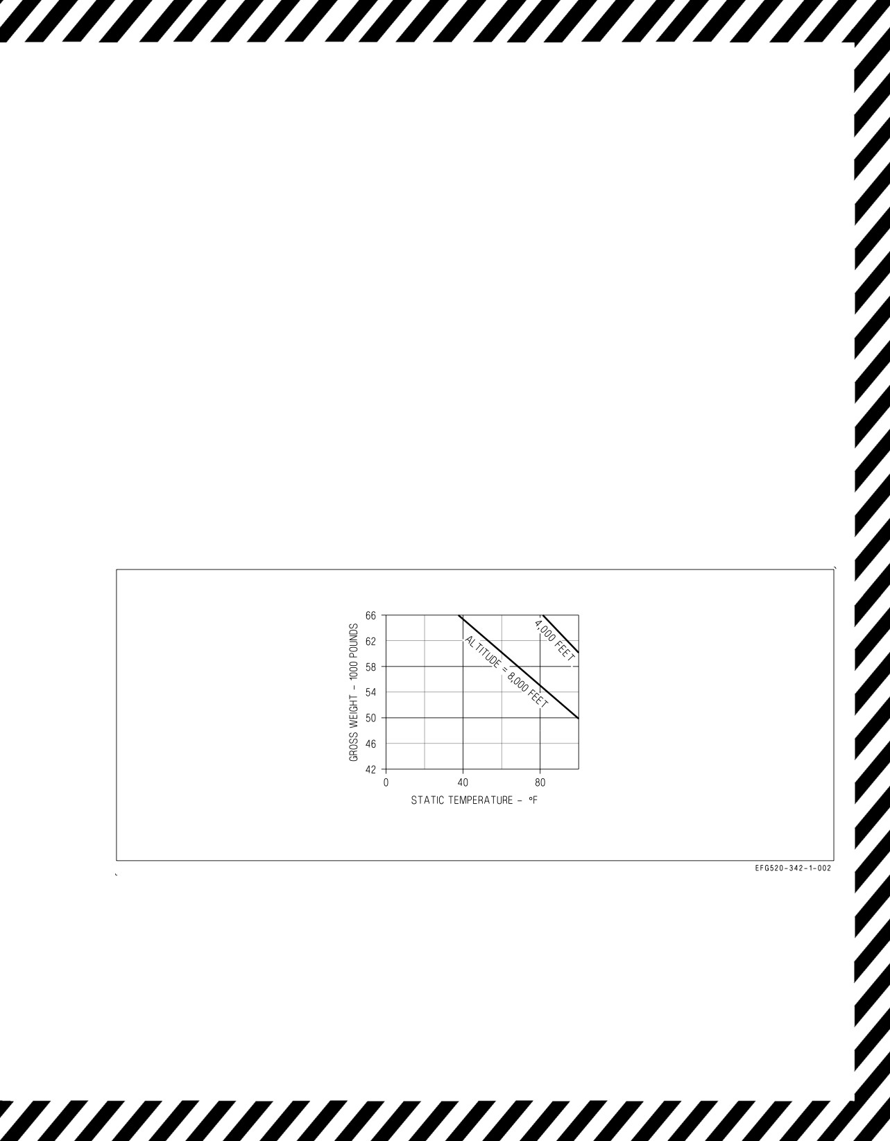
A1-E18GA-NFM-000
If flyaway airspeed not available -
*1. Select emergency brakes (if appropriate).
*2. HOOK handle - DOWN (if required)
If NWS failure suspected -
3. Paddle switch - PRESS
If takeoff is continued and blown tire suspected -
2. LDG GEAR handle - DO NOT CYCLE
3. Engine instruments - MONITOR FOR FOD INDICATIONS
4. ANTI SKID switch - OFF
5. Make a short field arrestment.
If decision to stop is made and blown tire suspected -
3. Do not retract flaps.
4. Do not taxi once stopped.
Figure 14-1. Maximum Weight for 100 fpm Single Engine Rate of Climb
V-14-5
ORIGINAL
A1-E18GA-NFM-000
14.5 LANDING GEAR FAILS TO RETRACT
If LDG GEAR handle cannot be moved from the DN position -
1. LDG GEAR handle - LEAVE DN (DO NOT OVERRIDE)
If landing gear warning light and warning tone on with the LDG GEAR handle UP -
1. LG circuit breaker - CHECK IN
2. LDG GEAR handle - DN (DO NOT CYCLE)
If three down and locked indications -
3. Land as soon as practical.
4. Consider an arrested landing (normal braking and NWS may not be available).
If any gear indicates unsafe -
5. Refer to Landing Gear Unsafe/Fails to Extend Procedure.
V-14-6
ORIGINAL
A1-E18GA-NFM-000
CHAPTER 15
Inflight Emergencies
15.1 AFTERBURNER FAILURE
Afterburner failure can be recognized by failure of the nozzle to open, which may be the only
symptom that is immediately recognizable. The afterburner receives continuous ignition any time the
throttle is above the MIL detent and afterburner lightoff is not yet detected. If an afterburner does not
light after selection or blows out, reduce the throttle to MIL and reselect afterburner. If an afterburner
fails to light on subsequent attempts, maintenance action is most likely required.
15.2 RESTART
Ignition is activated automatically whenever a flameout is sensed and the throttle is at or above IDLE. At
least 350 KCAS is required to maintain 12% rpm for a windmill airstart. When single engine, the hydraulic
system switches from 3,000 to 5,000 psi output pressure above approximately 500 KCAS/1.0 IMN (see figure
15-2). This results in additional horsepower extraction and reduced windmill rpm. The hydraulic system
output drops from 5,000 to 3,000 psi at approximately 480 KCAS/0.95 IMN. Therefore, maintain airspeed
below 480 KCAS/0.95 IMN to maximize the chance of a successful windmill restart.
Continuing automatic restart attempts at high altitude or high AOA may cause the engine to
overtemp. In this case, place the throttle OFF until in a better start environment. The optimum restart
envelope is below 25,000 feet. If the engine is shut down from a high power setting and rpm decays to
0%, temporary rotor binding may occur. In this case, engine rotation will not be regained until the
engine cools evenly (about 10 to 15 minutes). Windmill restart attempts made after rpm has degraded
to 0% may require up to 450 knots to obtain 12% rpm for ignition.
APU restart is the last alternative. If APU restart is required, HYD ISOL ORIDE should first be
selected for 10 seconds prior to APU start, assuming good HYD 2B. With the APU switch ON, and the
green READY light on, the engine crank switch may be used to crank the engine for restart. The APU
restart envelope is below 250 KCAS, below 10,000 ft. See figures 15-1 through 15-4.
Attempting to restart an engine that has flamed out for no apparent
reason may result in an engine bay fuel leak/fire.
If rpm above 30% -
1. Throttle affected engine - IDLE or above
If rpm below 30% -
1. Throttle good engine - 80% N2 rpm minimum.
2. ENG CRANK switch - L or R (affected side)
3. Throttle affected engine - IDLE or above
4. Monitor EGT during start (871°C maximum). FADEC will not prevent hot starts airborne.
V-15-1
ORIGINAL
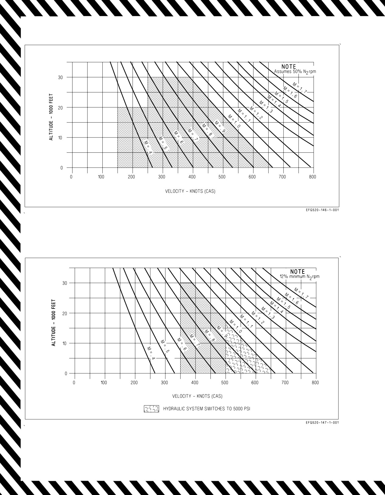
A1-E18GA-NFM-000
Figure 15-1. Spooldown Restart Envelope
Figure 15-2. Windmill Restart Envelope
V-15-2
ORIGINAL
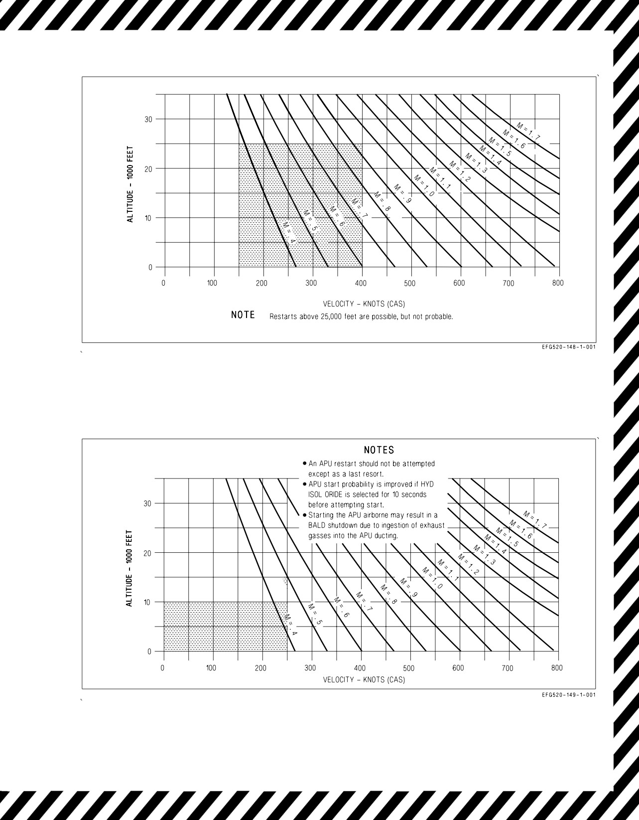
A1-E18GA-NFM-000
Figure 15-3. Crossbleed Restart Envelope
Figure 15-4. APU Restart Envelope
V-15-3
ORIGINAL
A1-E18GA-NFM-000
15.3 FUSELAGE FUEL LEAK
The possibility of fire is normally of prime concern with any fuel leak; however, with a massive leak,
the fuel loss itself must be dealt with promptly and correctly to ensure that sufficient fuel remains to
return to base. Fuel loss rates can be in excess of 1,000 ppm from failed main fuel lines. Left unchecked,
this leak can rapidly drain external tanks, both transfer tanks, and the feed tank on the leaking side.
Since leaks may occur upstream of the throttle-operated fuel shutoff valve in the fuel control, shutting
down the throttle may not stop the leak. Pressing the corresponding FIRE light closes the feed tank
fuel shutoff valve for that engine and stops fuel flow through the main fuel line.
The pilot may not be able to visually determine which side is leaking. Utilize a wingman, when
available, and check for secondary indications to determine the side of the leak. In addition to the
primary cockpit indications listed in the procedure, the following may also be indications of a fuselage
fuel leak: FUEL LO caution, erratic engine operation at high power settings, abnormal fuel flow
indications.
1. Afterburners - DESELECT
Afterburner operation with a fuselage fuel leak may result in a fire.
2. Analyze indications to determine which side is leaking:
• Visual confirmation of fuel leakage
• L or R BOOST LO caution
• FEED tank imbalance (lower feed tank)
• FUEL LO caution (lower feed tank)
• Erratic engine operation
If unable to confirm side -
3. Land as soon as possible.
If side confirmed -
3. Throttle affected engine - OFF
4. FIRE light affected engine - PUSH
Securing the good engine may result in flameout of both engines.
If fuel leak stops -
5. Land as soon as practical.
If fuel leak continues -
6. Land as soon as possible.
V-15-4
ORIGINAL
A1-E18GA-NFM-000
FOR LANDING (leak continues) -
1. Make normal vice arrested landing (if possible).
2. Use light braking.
After landing-
3. Turn aircraft into the wind.
4. Throttles - OFF
5. FIRE lights - PUSH
15.4 HYDRAULIC FAILURES
Hydraulic failures are indicated by the HYD 1A, 1B, 2A, and 2B circuit cautions described in
Chapter 12. The effects of losing one or more HYD circuits can be seen by analyzing the Hydraulic
Flow Diagram shown in figure 15-5. For multiple hydraulic circuit failures, the Hydraulic Subsystems
Malfunction Guide (figure 15-6) shows which flight control surfaces are lost.
V-15-5
ORIGINAL
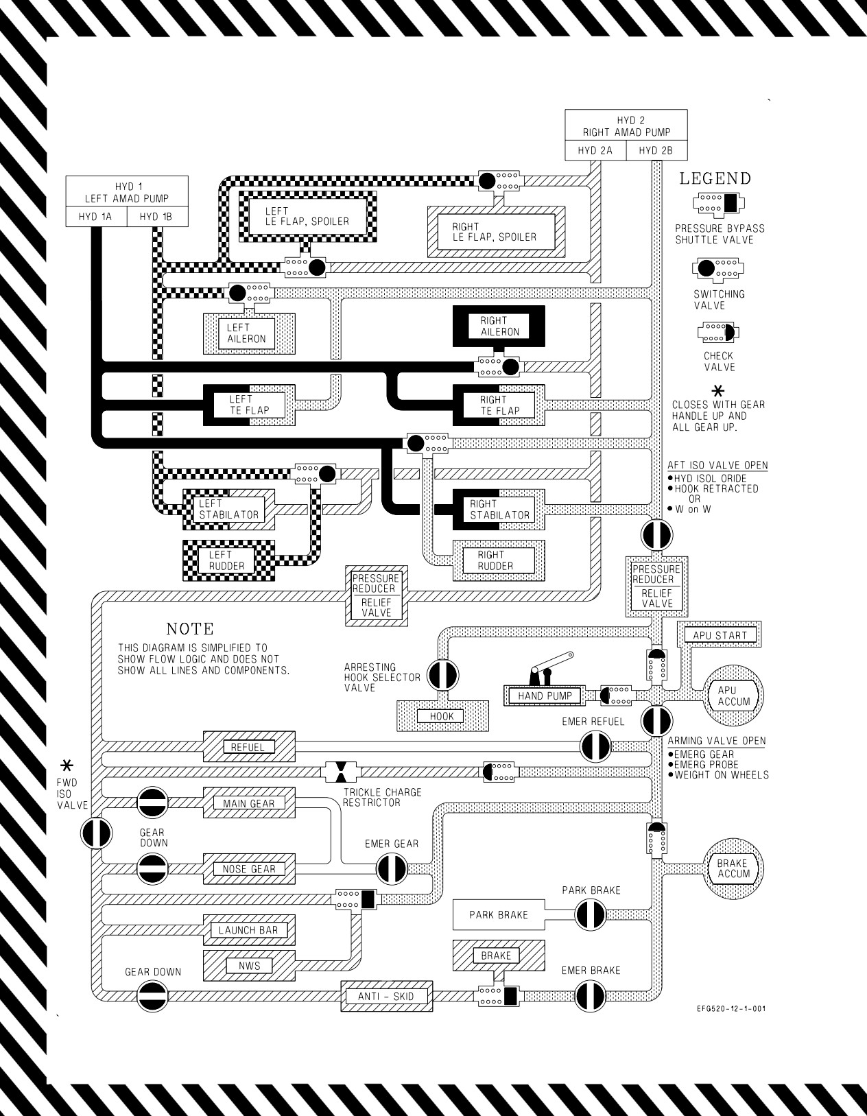
A1-E18GA-NFM-000
Figure 15-5. Hydraulic Flow Diagram (Aircraft on Deck)
V-15-6
ORIGINAL
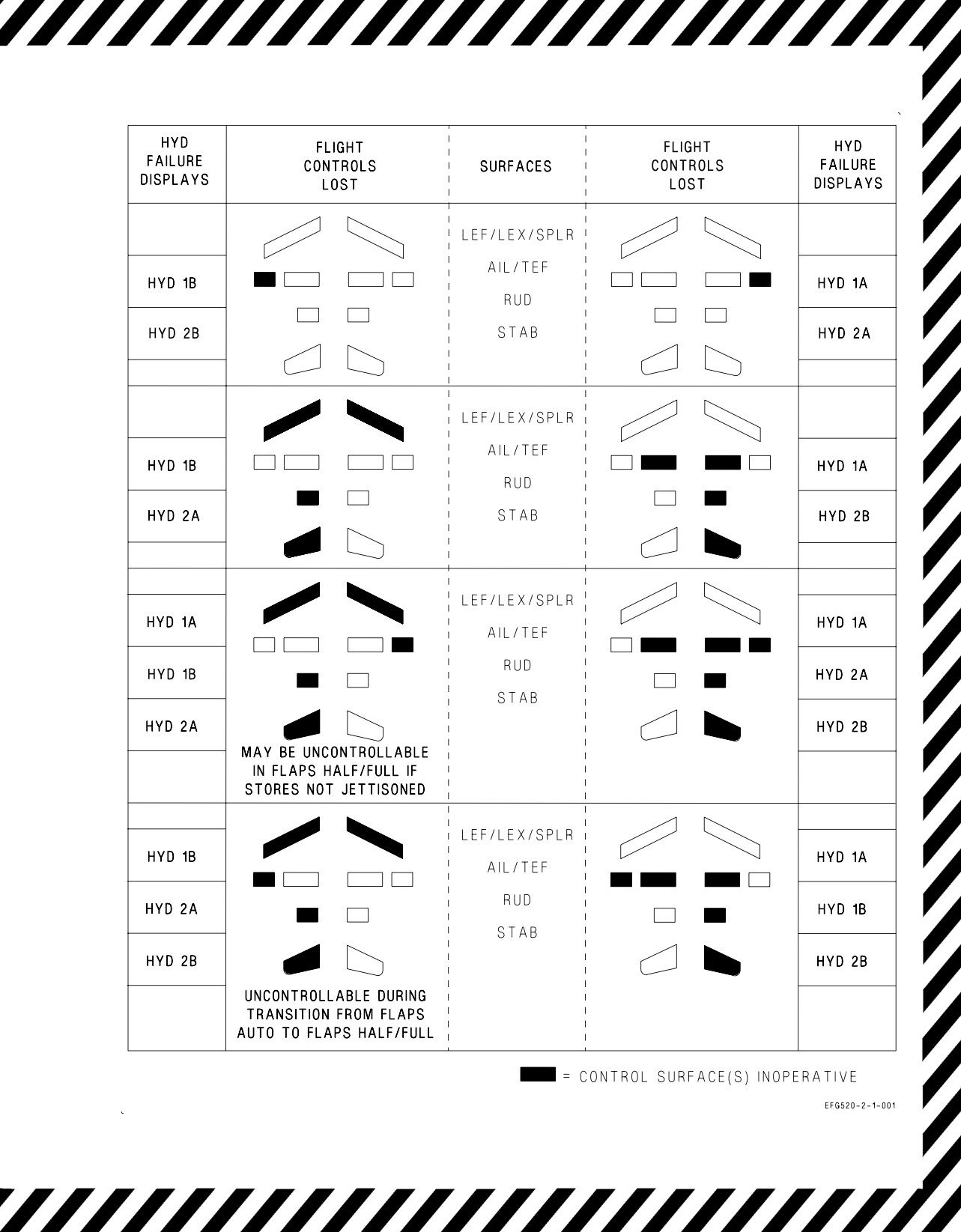
A1-E18GA-NFM-000
Figure 15-6. Hydraulic Subsystems Malfunction Guide
V-15-7
ORIGINAL
A1-E18GA-NFM-000
15.5
DOUBLE TRANSFORMER-RECTIFIER FAILURE
Failure of both transformer-rectifiers (TRs) can be recognized by loss of the HUD (but not the other
displays), bleed air including cockpit airflow/pressurization, and other equipment which operates on
the main dc busses. The FCC channels continue to be powered by their respective PMG outputs. The
Essential Bus is powered by the EBB PMGs with the battery charger and the battery as backups.
Therefore, the battery gauge should read greater than 24 vdc (26.5 nominal) and the BATT SW caution
light should be out.
With a dual TR failure, time is not critical, and essential bus equipment need not be turned off.
Equipment requiring ac power only will remain operable with a dual TR failure and need not be turned
off to conserve battery power. If the L or R DC FAIL caution lights illuminate, all three 28 volt dc
windings from the corresponding PMG are prevented from supplying FCC CH or essential bus backup
power. See the Emergency Power Distribution Charts (figure 15-7) for operative and inoperative
equipment.
1. BATT SW caution light - CONFIRM OUT
2. Electrical RESET button - PRESS
3. Maintain airspeed below 325 KCAS (300 to 325 KCAS optimum).
4. ECS MODE switch - OFF/RAM
5. AV COOL switch - EMERG
6. CABIN PRESS switch - RAM/DUMP
7. OBOGS control switch - OFF
8. Maintain altitude below 10,000 feet MSL prior to emergency oxygen depletion (10 to 20 minutes).
9. Consider removing mask and resetting emergency oxygen system once below 10,000 feet MSL.
10. Land as soon as practical.
If AV AIR HOT caution appears -
11. Non-essential avionics equipment - OFF (e.g., radar, UFCD controlled avionics, ECM,
sensors, MC2)
12. Land as soon as possible.
For landing -
13. Perform Landing Gear Emergency Extension Procedure.
14. Make a short field arrestment (if available).
15. Use emergency brakes with steady brake pressure. (Anti-skid is not available.)
V-15-8
ORIGINAL
A1-E18GA-NFM-000
BOTH GENERATORS INOPERATIVE
OPERATIVE EQUIPMENT
LIGHTING EQUIPMENT
ENGINE
FLIGHT CONTROLS
Caution lights panel
Afterburner ignition
CAS
(less GEN and FUEL LO lights)
Anti-icing
Flaps
CABIN light may be on but is not accurate
APU ready light
Flap position indicator
CK ECS light is not fully functional
APU start
Master caution lights
Bleed air leak detectors
Utility flood lights
Engine ignition
Engine start
FLIGHT INSTRUMENTS
NAVIGATION
Fire detectors and extinguishers
Front cockpit standby attitude
1
COMM 1 R/T
Engine fuel display
reference indicator
IFF emergency
(RPM and EGT only)
Standby airspeed/Mach indicators
Tank 4 scavenge pump
Standby altimeters
OTHER
Wing transfer
Standby rate-of-turn indicators
Arresting hook extension
Standby turn needles
Canopy
Emergency air refueling
Emergency jettison
FCS ram air selection
Intercom
Landing gear (emergency system)
Landing gear position indicator
Voice alerts (APU fire,
engine fire, bleed air)
INOPERATIVE EQUIPMENT
OTHER
AEA pallet
ENGINE
LIGHTING EQUIPMENT
Air refueling light and normal probe
Anti-ice control
Approach lights
extension
Bleed air system
Caution/advisory displays
ALQ-218
Engine fuel display
CK ECS light is not fully functional
Anti-skid
(all functions except RPM
Console lights
Arresting hook retraction
and EGT)
Flood lights
Battery charger
External fuel transfer
Formation lights
CPWS pressure sensing
Fuel CG control/fuselage transfer
GEN caution lights
CSC interference blanker
Fuel dump
Instrument lights
DDIs/MPCD/UFCD
FUEL LO warning light
Landing/taxi lights
Data link
Fuel thermal mgmt
Light test switch
Hook warning light
Fuel transfer pressure light
Nav flood lights
Hydraulic pressure indicator
Inlet ice detector
Position lights
JHMCS
Internal wing fuel inhibit
Strobe lights
Landing gear (normal system)
N1 lockup
Landing gear warning tone
Tank 4 transfer pump
NAVIGATION EQUIPMENT
Master caution tone
COMM 2 R/T
MATT
FLIGHT CONTROLS
DMS
OBOGS
Autopilot
ICLS, IFF, INS/ANAV
OBOGS monitor
INCANS
Radar
FLIGHT INSTRUMENTS
KY-58
ALR-67
Aft cockpit standby ARI
Radar altimeter
CVRS
AOA indexer lights
Radar beacon
Selective jettison
HUD
TACAN
Voice alerts
(fuel low, bingo, altitude,
L & R AOA heaters
flight computer hot, flight controls,
L & R pitot static/total temp
Mode 4 reply, engine)
heaters
Weapon fire/launch/release
MC 1/2
Windshield anti-ice/rain removal
Total temperature probe
1
Frequency selection lost. Will operate on last selected frequency. Guard transmit receive can be selected by COMM G XMT switch.
Figure 15-7. Emergency Power Distribution (Sheet 1 of 4)
V-15-9
ORIGINAL
A1-E18GA-NFM-000
BOTH TRANSFORMER-RECTIFIERS INOPERATIVE
BOTH GENERATORS OPERATIVE
OPERATIVE EQUIPMENT
FLIGHT INSTRUMENTS
Front cockpit standby ARI
NAVIGATION EQUIPMENT
Left and right pitot static/Total
2
COMM 1 R/T
ENGINE
temperature heaters
IFF
Afterburner ignition
Standby airspeed/Mach indicators
IFF (emergency)
Anti-icing
Standby altimeters
INS/ANAV
APU ready light
Standby rate-of-climb indicators
Radar altimeter
APU start
Standby turn needles
Bleed air leak detectors
OTHER
Engine fuel display engine start
LIGHTING EQUIPMENT
Arresting hook extension
Engine ignition
Caution/advisory displays
Battery charger
Fire detectors and extinguishers
Caution lights panel (less GEN
Canopy
Fuel dump
and FUEL LO lights)
DDIs/MPCD/UFCD
Internal fuel transfer
CABIN light may be on but is not accurate
Emergency air refueling
Tank 4 scavenge pumps
CK ECS light is not fully functional
Emergency jettison
Wing transfer
Console lights
FCS ram air selection
Emergency instrument light
Hydraulic pressure indicator
FLIGHT CONTROLS
Flood lights
Intercom
All channels autopilot
Instrument lights
JHMCS
All channels are operative
Master caution lights (and tone)
Landing gear (emergency system)
CAS
NVG floodlights
Landing gear position indicator
Flaps
Position lights
Voice alerts (all)
Flap position indicator
Utility floodlights
INOPERATIVE EQUIPMENT
OTHER
AEA pallet
FLIGHT INSTRUMENTS
ALQ-218
AOA indexer lights
ALR-67
ENGINE
HUD
Air refueling lights and
Anti-ice
normal probe extension
Bleed air system
LIGHTING EQUIPMENT
Anti-skid
External fuel transfer
Approach lights
Arresting hook retraction
Fuel c.g. transfer
CK ECS light is not fully functional
Cabin ram air selection
FUEL LO warning light
Formation lights
CPWS pressure sensing
Fuel tank pressure light
GEN caution lights
CVRS
Fuel thermal mgmt
Landing/taxi lights
Data link
Inlet ice detector
Lights test switch
DMD
Internal wing fuel inhibit
Strobe lights
Hook warning light
N1 lockup
Landing gear (normal system)
NAVIGATION EQUIPMENT
Landing gear warning tone
COMM 2 R/T
MATT
DMS
Nosewheel steering
ILS
OBOGS
INCANS
OBOGS monitor
KY-58
Radar
Radar beacon
Selective jettison
TACAN
Weapon fire/launch/release
Windshield anti-ice removal
2
Backup mode operative only.
Figure 15-7. Emergency Power Distribution (Sheet 2)
V-15-10
ORIGINAL
A1-E18GA-NFM-000
LEFT GENERATOR INOPERATIVE - BUS TIE OPEN
OPERATIVE EQUIPMENT
OTHER
Anti-skid
ENGINE
Arresting hook extension and retraction
FLIGHT CONTROLS
Afterburner ignition
Audio tones
Autopilot
Anti-ice control
Battery charger
CAS
Anti-icing
Cabin ram air selection
Flaps
APU ready light
Canopy
Flap position indicator
APU start
CPWS
Speedbrake
Bleed air leak detectors
CVRS
Speedbrake advisory light
Bleed air system
Data link
Engine fuel display
DMD
Engine ignition
ECS
NAVIGATION EQUIPMENT
Engine start
Emergency air refueling
COMM 1 R/T
External fuel transfer
Emergency jettison
IFF (less Mode 4)
Fire detectors and extinguishers
FCS ram air selection
IFF emergency
Fuel dump
Hook warning light
INCANS
Fuel quantity
Intercom
KY-58
Fuel tank pressure light
Interface blanker
Radar altimeter
Inlet ice detector
JHMCS
Radar beacon
Internal wing fuel inhibit
Landing gear (emergency system)
N1 lockup
Landing gear (normal system)
LIGHTING EQUIPMENT
Tank 1 transfer pump
Landing gear position indicator
Approach lights
Tank 4 scavenge pump
Landing gear warning tone
Caution lights panel (less FUEL LO light)
Wing diverter valves
Master caution tone
Emergency instrument light
Wing transfers
Nosewheel steering
Forward console, flood and instrument
OBOGS monitor
lights
FLIGHT INSTRUMENTS
RDDI
Lights test switch
AOA indexer lights
Selective jettison (stations 6 thru 10 only)
Master caution lights
HUD
Voice alerts (APU fire, engine fire
NVG floodlights
Right pitot static/total temp heaters
bleed air)
Position lights
Front cockpit standby ARI
Weapons launch/release (stations 6 thru
Utility floodlights
Standby airspeed/Mach indicators
10 only)
Standby altimeters
Windshield anti-ice/rain removal
Standby rate-of-climb indicators
Standby turn needles
INOPERATIVE EQUIPMENT
OTHER
AEA pallet
ENGINE
AEA ECS valve
LIGHTING EQUIPMENT
FUEL LO warning light
Air refueling light
AFT console, flood and instrument lights
Tank 4 transfer pump
ALQ-218
Caution/advisory/display
ALR-67
Formation lights
FLIGHT INSTRUMENTS
LDDI/MPCD/UFCD
Landing/taxi lights
L AOA probe heater
MATT
Strobe lights
L pitot static/total temp heater
Nozzle indication on EFD
MC 1
OBOGS
NAVIGATION EQUIPMENT
Total temp probe heater
Radar
DMS
ILS
3
Selective jettison (stations 2 thru 5 only)
INS/ANAV
Voice alerts
(fuel low, bingo, altitude,
TACAN
flight computer hot, flight controls,
Mode 4 reply, engine)
3
Weapon fire/launch/release
(Station
2
thru 5 only)
3
Failure of stations 2 thru 5 will not be indicated on DDI until SMS attempts to communicate with failed stations.
Figure 15-7. Emergency Power Distribution (Sheet 3)
V-15-11
ORIGINAL
A1-E18GA-NFM-000
RIGHT GENERATOR INOPERATIVE - BUS TIE OPEN
OPERATIVE EQUIPMENT
OTHER
ENGINE
AEA pallet
Afterburner ignition
ALR-67
Anti-ice control
FLIGHT CONTROLS
Air refueling light and normal probe
Anti-icing
Autopilot
extension
APU ready light
CAS
Anti-skid
APU start
Flaps
Arresting hook extension and retraction
Bleed air leak detectors
Flap position indicator
Audio tones (less Master Caution)
Bleed air system
Speedbrake
Cabin ram air selection
Engine fuel display
Speedbrake advisory light
Canopy
Engine ignition
CPWS
Engine start
NAVIGATION EQUIPMENT
Data link
External fuel transfer
COMM 1 R/T
ECS (cold cockpit, defog air flow)
Fire detectors and extinguishers
COMM 2 R/T
Emergency air refueling
Fuel Dump
DMS
Emergency jettison
FUEL LO warning light
IFF (Less Mode C)
FCS ram air selection
Fuel tank pressure light
IFF emergency
Hook warning light
Internal wing fuel inhibit
ILS
Intercom
N1 lockup
INS/ANAV
Landing gear (emergency system)
Tank 4 transfer pump
Radar beacon
Landing gear (normal extension)
Wing diverter valves
Landing gear position indicator
Wing transfer
LIGHTING EQUIPMENT
Landing gear warning tone
Aft console, flood and instruments lights
LDDI/MPCD/UFCD
FLIGHT INSTRUMENTS
Caution lights panel
MATT
AOA indexer lights
Formation lights
Nosewheel steering
Front cockpit standby attitude
Landing/taxi lights
OBOGS
reference indicator
Lights test switch
OBOGS monitor
Left AOA heater
Master caution lights
Radar
Left pitot static/total temp heater
NVG floodlights
2
Radar coolant pump
Standby airspeed/Mach indicator
Strobe lights
Standby altimeters
Utility floodlights
Voice alerts (APU fire, engine fire,
Standby rate-of-climb indicators
bleed air)
Standby turn needles
Windshield anti-ice/rain removal
INOPERATIVE EQUIPMENT
ENGINE
OTHER
Inlet ice detector
LIGHTING EQUIPMENT
ALQ-218
Tank 1 transfer pump
Approach lights
Battery charger
Forward console, flood instrument lights
CSC
FLIGHT INSTRUMENTS
Position lights
CVRS
AOA indexer lights
Hydraulic pressure indicator
Aft cockpit standby attitude
NAVIGATION EQUIPMENT
Interference blanker
reference indicator
INCANS
JHMCS
HUD
Radar altimeter
Master caution tone
MC 2
RDDI
R AOA heater
Selective jettison
R pitot static/total temp heater
Voice alerts
(fuel low, bingo, altitude,
flight computer hot, flight controls,
Mode 4 reply, engine)
Weapon fire/launch/release
2
Back-up mode operative only.
Figure 15-7. Emergency Power Distribution (Sheet 4)
V-15-12
ORIGINAL
A1-E18GA-NFM-000
15.6 COCKPIT TEMPERATURE HIGH
Hot cockpit airflow may be caused by an ECS control failure or a valve failure. Selecting full COLD
on the CABIN TEMP knob should shut off warm air to the cockpit. If this procedure fails to secure
warm air to the cockpit, then the failure is most likely with the cockpit flow valve itself. If this is the
case, securing both BLEEDS may be the only means to stop the flow of warm air.
Selection of MAN with the ECS MODE switch is prohibited. Selection of
MAN while the aft cooling fan shutoff valve is open may cause the fan to
overspeed resulting in a catastrophic fan failure potentially leading to loss
of OBOGS.
In ECS MAN mode, cockpit temperature can reach 190°F, if the cockpit
flow valve is stuck full open.
1. CABIN TEMP knob - FULL COLD
If temperature still high -
2. Maintain altitude below 25,000 feet.
3. CABIN PRESS switch - RAM/DUMP
If temperature not reduced -
4. Emergency oxygen green ring - PULL
5. OXY FLOW knob - OFF
6. BLEED AIR knob - OFF (DO NOT CYCLE)
7. Maintain altitude below 10,000 feet MSL prior to emergency oxygen depletion (10 to 20 minutes).
Under less than optimal conditions (low altitude, heavy breathing, loose
fitting mask, etc.) as few as 3 minutes of emergency oxygen may be
available.
8. Maintain airspeed below 325 KCAS (300-325 KCAS optimum).
9. ECS MODE switch - OFF/RAM
10. AV COOL switch - EMERG
V-15-13
ORIGINAL
A1-E18GA-NFM-000
Once below 10,000 feet MSL -
11. Consider removing mask and resetting emergency oxygen.
12. OXY FLOW knob - OFF
13. OBOGS control switch - OFF
If AV AIR HOT caution appears -
14. Non-essential avionics equipment - OFF (e.g., radar, UFCD controlled avionics, ECM, sensors,
MC2)
15. Land as soon as possible.
15.7 COCKPIT SMOKE, FUMES, OR FIRE
Consider all unidentified fumes in the cockpit as toxic. Do not confuse condensation from the ECS.
The most probable source of visible smoke or fumes in the cockpit is from the engine bleed air or
residual oil in the ECS ducts. This smoke is blue gray in color, has a characteristic pungent odor, and
may cause the eyes to sting. Another source of smoke or fumes is an electrical malfunction or overheat
of equipment located in the cockpit. In the event of an electrical short or overload condition, this
equipment may generate electrical smoke (usually white or gray in color) but should not cause an open
fire since cockpit equipment uses very little electrical current. Cockpit electrical wiring insulation may
smolder and create smoke, but will not erupt into a seriously damaging fire.
*1. Emergency oxygen green ring(s) - PULL
*2. OXY FLOW knob(s) - OFF
*3. Initiate rapid descent to below 10,000 feet cabin altitude.
*4. CABIN PRESS switch - RAM/DUMP
• DCS may be experienced when operating in an unpressurized cabin
above 25,000 feet MSL even with a working oxygen system. Symptoms
of DCS include pain in joints, tingling sensations, dizziness, paralysis,
choking, and/or loss of consciousness.
• Under less than optimal conditions (low altitude, heavy breathing,
loose fitting mask, etc.) as few as 3 minutes of emergency oxygen may
be available.
5. Maintain airspeed 200 to 300 KCAS.
6. OBOGS control switch - OFF
7. Maintain altitude below 10,000 feet MSL prior to emergency oxygen depletion (10-20 minutes).
8. Consider resetting emergency oxygen system once below 10,000 feet MSL.
V-15-14
ORIGINAL
A1-E18GA-NFM-000
If smoke and fumes persist -
9. BLEED AIR knob - OFF (DO NOT CYCLE.)
10. AV COOL switch - EMERG
If smoke and fumes persist or fire present -
11. All electrical equipment - OFF
12. UFCD controlled avionics - OFF
(AC power is required.)
13. Required electrical equipment - ON
Restore power to equipment one at a time.
If smoke/fire starts again, secure that equipment.
If unable to clear smoke -
14. Slow and jettison canopy. Secure all loose articles and ensure helmet visor is down. The rear
crewmember should lower the seat and lean as far forward as possible before jettisoning canopy.
15.8 HYPOXIA/LOW MASK FLOW
*1. Emergency oxygen green ring(s) - PULL
*2. OXY FLOW knob(s) - OFF
*3. Initiate rapid descent to below 10,000 feet cabin altitude.
Under less than optimal conditions (low altitude, heavy breathing, loose
fitting mask, etc.) as few as 3 minutes of emergency oxygen may be
available.
4. OBOGS control switch - OFF
If hypoxic symptoms persist -
5. Remain on emergency oxygen as long as possible.
6. Land as soon as possible.
Once below 10,000 feet cabin altitude and hypoxic symptoms removed -
7. Consider removing mask and resetting emergency oxygen system or resuming normal OBOGS
operation if flow appears normal and donning of mask is desired.
8. Land as soon as practical.
V-15-15
ORIGINAL
A1-E18GA-NFM-000
15.9 LOSS OF CABIN PRESSURIZATION
Decompression sickness (DCS) becomes a physiological concern at exposures to cabin altitudes in
excess of 18,000 feet. The potential for DCS increases at exposures above 25,000 feet or in the case of
a rapid decompression. Aircrew exposed to these conditions should be alert for the symptoms of DCS.
*1. Emergency oxygen green ring(s) - PULL
*2. OXY FLOW knob(s) - OFF
*3. Initiate rapid descent to below 10,000 feet cabin altitude.
4. CABIN PRESS switch - CHECK NORM
5. ECS MODE switch - CHECK AUTO
DCS may be experienced when operating in an unpressurized cabin above
25,000 feet MSL even with a working oxygen system. Symptoms of DCS
include pain in joints, tingling sensations, dizziness, paralysis, choking,
and/or loss of consciousness.
If DCS or hypoxia symptoms present -
6. Maintain altitude below 10,000 feet MSL.
7. Land as soon as possible.
If DCS or hypoxia symptoms not present -
6. Reset emergency oxygen system and resume normal OBOGS operation.
7. Maintain altitude below 25,000 feet MSL.
8. Land as soon as practical.
15.10 DISPLAY MALFUNCTION
If a display malfunctions (stale data or DDI pushbuttons do not work), attempt to restore by cycling
display power. If cycling power to the display does not fix the problem, cycling the corresponding
mission computer may restore the DDI (cycle MC1 for LDDI, MC2 for RDDI). HUD symbology is
driven by either MC1 or MC2. If the UFCD malfunctions, attempt to restore by cycling the MPCD or
8 x 10 display.
If all displays are flashing STANDBY, and a backup HUD is displayed in the front cockpit, a dual
MC failure has occurred.
15.11 DUAL MISSION COMPUTER (MC) FAILURE
A dual MC failure is recognized by STANDBY flashing on the HUD and L/RDDIs. In the front
cockpit, a backup HUD format (driven by the SDC) is displayed on the MPCD and UFCD. After
cycling an MC, the corresponding display (LDDI for MC1, RDDI for MC2) continues to flash
STANDBY for approximately 11 seconds while the MC boots up.
V-15-16
ORIGINAL
A1-E18GA-NFM-000
1. MC switch - CYCLE TO 1 OFF, THEN TO 2 OFF
After 15 seconds, if MC1 is restored (MC1 Backup Mode) -
2. MC switch - MOVE FROM 2 OFF TO NORM
15.12 OCF - OUT-OF-CONTROL FLIGHT
Selection of manual spin recovery mode (SPIN switch in RCVY) seri-
ously degrades controllability, will prevent recovery from any departure
or spin, and is prohibited.
15.12.1 Departure from Controlled Flight. A typical departure occurs as a yaw divergence (nose-
slice) followed by an uncommanded roll in the same direction. The yaw divergence can happen very
quickly; therefore, the yaw rate tone may not provide sufficient departure warning. Usually, a
departure is preceded by a slow buildup in sideslip and uncomfortable sideforces. The buildup of
sideslip is accompanied by ″vortex rumble″; however, vortex rumble may not be noticed during
aggressive maneuvering. Therefore, excessive sideforce provides the most reliable departure warning
cue to the pilot. The initial phase of the departure is not particularly violent or disorienting unless it
occurs at high airspeed or Mach number. Recognition of these cues permits neutralization of the
controls and avoidance of a departure.
15.12.1.1 Departures with Lateral Weight Asymmetries. Complying with NATOPS limits for
asymmetric store loadings is required to prevent departures. Aggressive longitudinal maneuvering
beyond NATOPS AOA limits may result in a yaw departure away from the heavy wing, which cannot
be controlled with lateral stick or pedal inputs. At low airspeed, recovery is immediate when AOA is
reduced below NATOPS limits. At higher airspeed, more violent and sudden departures may occur
with little or no warning when maneuvering aggressively beyond NATOPS limits. In such cases, the
resulting post-stall gyrations rapidly transition to an upright spin away from the heavy wing.
15.12.1.2 Departure Recovery. Recovery is generally very prompt, on release of the controls. Some
departures, particularly from inadvertent tailslides, may exhibit large transitory sideslips or negative
g rolls prior to positive recovery. Sideslip type departures yield excessive gravity-induced sideslip at
relatively slow airspeeds (<90 KCAS) and can quickly develop into a spin. In the absence of a steady
spin arrow, controls should remain neutral throughout all such post departure motion, as CAS reliably
regains control. Any pilot input will delay recovery or precipitate further departure. For departure
recoveries that stabilize in a negative g stall, application of aft stick may be used to finish the recovery.
15.12.2 Spin. Spin is confirmed by a steady spin arrow or the presence of a sustained yaw rate,
elevated positive or negative AOA, and airspeed less than 150 KCAS. Spin arrows very reliably indicate
the appropriate recovery action. While some departures may generate sufficient yaw rate to trip the
command arrow, they are typically self-recovering by the time the arrow is displayed, and the arrow
will quickly disappear. Therefore, with the spin arrow present, a brief hesitation is all that is required
to confirm a steady, valid arrow prior to applying anti-spin lateral stick.
15.12.2.1 Spin Recovery. The command arrow indicates the proper control stick position for
upright or inverted spins. For upright spins, the command arrow directs the pilot to apply full lateral
stick with the spin direction. For inverted spins, the command arrow directs the pilot to apply full
V-15-17
ORIGINAL
A1-E18GA-NFM-000
lateral stick opposite the spin direction. In general, spin recovery is straightforward and reliable if the
OCF procedures are followed and sufficient altitude remains. For lateral weight asymmetry loadings,
recoveries from upright spins away from the heavy wing are essentially identical to the symmetrical
loaded airplane. Spin recoveries for less common upright spins into the heavy wing, and inverted spins,
were sometimes delayed due to the oscillatory nature of the spin. Recovery begins immediately but
may take up to one turn to become apparent. Recovery from a fully developed spin may include high
roll rates with significant negative g unloads, which, though disorienting and uncomfortable, should be
interpreted as a positive indication of imminent recovery. When the command arrow is removed,
lateral stick should be smoothly returned to neutral. Maintaining anti-spin lateral stick after the
command arrow has disappeared may transition the recovering spin into a controllable roll that could
delay recovery.
15.12.3 OCF Recovery Procedures
*1. Controls - RELEASE, FEET OFF RUDDERS, SPEEDBRAKE IN
If still out of control -
*2. Throttles - IDLE
*3. Altitude, AOA, airspeed, and yaw rate - CHECK
If command arrow present -
*4. Lateral stick - FULL WITH ARROW
When command arrow removed -
*5. Lateral stick - SMOOTHLY NEUTRAL
When recovery indicated by AOA and yaw rate tones removed, side forces subsided, and
airspeed accelerating above 180 knots -
*6. Recover.
Failure to ensure all criteria are met may result in departure during
recovery.
Passing 6,000 ft AGL, dive recovery not initiated -
*7. Eject.
Post departure dive recovery initiated below 6,000 ft AGL is not assured.
Delaying the ejection decision below 6,000 ft AGL while departed may
result in unsuccessful ejection.
V-15-18
ORIGINAL
A1-E18GA-NFM-000
15.12.4 Post Departure Dive Recovery
1. One-g roll to the nearest horizon.
2. Throttles - MAX (MIL if altitude not critical)
3. Pull to and maintain 25° to 35° AOA until positive rate of climb established.
A positive rate of climb requires wings level pitch attitude (waterline)
greater than indicated AOA.
If aircraft departs during dive recovery below 6,000 ft AGL -
4. Eject
15.13 CONTROLLABILITY CHECK
Requirement: Malfunction, failure, or damage, which degrades approach and landing character-
istics.
Purpose (to determine):
• Whether to attempt an approach or a controlled ejection.
• Safe landing configuration.
• Safe final approach airspeed/AOA.
1.
Climb to and maintain a safe altitude in VMC:
• 15,000 feet AGL (recommended)
• At or above 5,000 feet AGL (if practical)
2.
Coordinate a visual inspection (if possible).
3.
Plan to configure aircraft and conduct controllability check as close to field/CV as possible
(avoid populated areas if able).
• In all cases, consider BINGO fuel requirements.
4.
Reference the appropriate emergency procedure to plan the following:
• Normal or Emergency Landing Gear Extension
• Appropriate flap setting for controllability check and landing
• AOA and/or airspeed limitations
• Any controllability issues that may arise from landing gear and/or flap extension
• Desired landing gross weight and fuel dump plan
5.
Consider Select Jettison stores prior to gear extension if:
• Lateral weight asymmetry is over 12,000 ft−lb to establish a more symmetric configuration
• Emergency Landing Gear extension required (i.e. no HYD 2A)
• Stated in appropriate emergency procedure
V-15-19
ORIGINAL W/IC1
A1-E18GA-NFM-000
If single engine −
6. Reduce gross weight (48,000 lb max, lower if practical).
7. Maintain operating engine above 80% RPM during flap and landing gear extension.
8. Do not exceed 15° AOB in turns (if possible).
If normal landing gear extension possible (i.e. no HYD2A caution) −
9. Slow to below 250 KCAS.
10. LDG GEAR handle − DN
If normal landing gear extension not possible −
9.
Execute Landing Gear Emergency Extension procedure.
• Do not configure flaps during Landing Gear Emergency Extension.
• Return to Controllability Check procedure once gear extended.
Once landing gear down and locked −
10. DO NOT TRIM until minimum controllable airspeed is determined.
11. Crosscheck AOA and airspeed during decel.
12. FLAP switch − AUTO/HALF/FULL based on:
• Flap setting stated in appropriate emergency procedure
• If single engine, flaps HALF
• Consideration of type landing, failure/damage, engine performance, etc.
13. Determine minimum controllable airspeed by slowing in 10 knot increments.
• If still controllable at AOA limit stated in appropriate emergency procedure or on−speed, plan
on flying appropriate AOA for approach and landing.
• If one−half stick or rudder pedal deflection required to maintain balanced flight prior to AOA
limit stated in appropriate emergency procedure or on−speed, add 10 knots for airspeed to be
used during approach and landing.
• If lateral stick required for balanced flight, plan for turns in the direction of stick
displacement (if possible).
14. Assess:
• Controllability in a 15° AOB turn
• Throttle response and wave−off maneuver
If controllability unacceptable to attempt landing −
15. Consider a controlled ejection over an unpopulated area (if possible).
If controllability acceptable to attempt landing −
15. Fly a straight−in approach.
• Do not exceed minimum−controllable−airspeed−plus−10 knots, or equivalent AOA, as
determined during controllability check.
V-15-20
ORIGINAL W/IC1
A1-E18GA-NFM-000
If single engine −
16. Execute Single Engine Approach and Landing procedure.
If dual engine −
16. Return to appropriate emergency procedure to ensure all corrective action steps are
completed prior to attempting approach to landing.
17. If arrested landing desired/required, consider effects of approach speed on max arresting−
gear engagement speed.
18. If controllability changes or safe landing is not certain at any point on approach, execute
wave−off/missed approach immediately.
15.14 EXTERNAL STORES JETTISON
Refer to External Stores Jettison Chart (figure 15-8).
15.15 EMERGENCY TANKER DISENGAGEMENT
Emergency tanker disengagement may be required if difficulties occur in either the tanker or the
receiver aircraft. Emergency breakaway signals are by radio transmission and/or turning on the lower
anti-collision lights. If the situation allows, normal, but expeditious, disconnect procedures should be
followed to minimize the possibility of aircraft damage.
The following procedures may result in damage to the tanker and/or
receiver aircraft.
1. Throttles - IDLE
2. SPEEDBRAKE switch - AFT
V-15-20A (Reverse Blank)
W/IC1
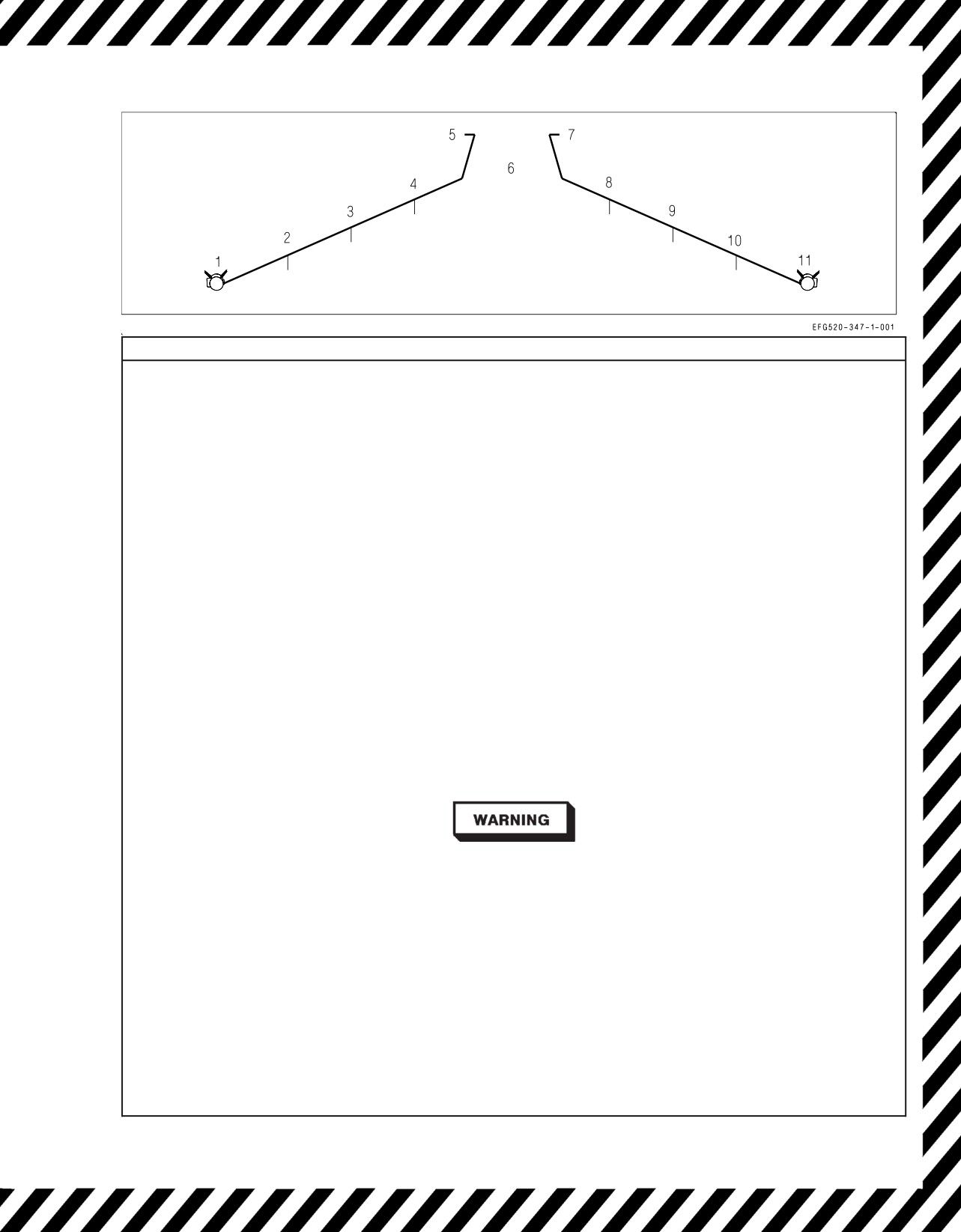
A1-E18GA-NFM-000
EMERGENCY JETTISON
Requirements: WoffW or LDG GEAR handle UP
1. EMERG JETT button - PUSH Jettison all stores/racks/launchers sequential by station pairs: 3 & 9, 2 & 10, 4 & 8, then 6 (100 ms)
SELECTIVE JETTISON
Requirements:
(1) WoffW, (2) LDG GEAR handle UP, (3) All landing gear up and locked
1. Find a clear area (if possible).
2. LT TEST switch - TEST Verify all JETT STATION SELECT buttons are illuminated.
3. JETT STATION SELECT buttons - SELECT DESIRED STATIONS (CTR, LI, RI, LM, RM, LO, RO)
4. SELECT JETT knob - ROTATE (as required)
a. L FUS MSL - Left fuselage missile
b. R FUS MSL - Right fuselage missile
c. RACK/LCHR - Rack/launcher (jettisons whatever is attached to the selected parent racks)
d. STORES - (1) Jettisons ordnance loaded on selected parent racks, CVERs, or IMERs;
(2) Jettisons missiles attached to launchers on selected stations except HARM;
(3) HARM anti-compromise launch.
5. SIM mode - UNBOXED
6. MASTER ARM switch - ARM
7. SELECT JETT button - PUSH Jettison sequential by selected stations: RM, LM, RI, LI, CL, RO, LO (350 ms)
After jettison -
8. MASTER ARM switch - SAFE
9. SELECT JETT knob - SAFE
NOTE
• Outboard station ADU-773 missile rails cannot be jettisoned, since they are installed in place of a BRU-32 rack.
• If multiple stations selected for STORE jettison include AGM-88s, the first HARM in the default sequence is launched first, then
the sequence continues from that station, releasing the remaining selected non-HARM stores. Regardless of the number
selected, only one HARM is launched each time the SELECT JETT button is pushed.
• With the SELECT JETT knob rotated out of the SAFE position, the SMS unlocks all racks/launchers. When SAFE is reselected,
racks/launchers are not locked again until commanded by either lowering the landing gear or selecting SIM mode.
AUX RELEASE
Requirements: (1) station must be HALKD or HAULK following a failed normal release or SELECT JETT attempt, (2) WoffW, (3)
MASTER ARM switch - ARM (SIM unboxed), (4) auxiliary cartridge installed in the HUNG parent rack.
During an AUX REL, the Mk 19 auxiliary cartridge is fired, opening the selected parent rack’s hooks and allowing the attached
store or rack/launcher to free fall from the aircraft. Lacking a forced ejection, this release mode is prohibited except in an
emergency and then only in 1.0g level flight.
NOTE
A Mk 19 auxiliary cartridge is not installed in a parent rack when a wing station is loaded with an IMER, a HARM, a Maverick, a
Harpoon, or a SLAM.
1. Find a clear area (if possible).
2. LT TEST switch - TEST Verify all jettison pushtiles are illuminated.
3. AUX REL switch - ENABLE
4. Jettison pushtiles - SELECT HUNG STATION(S)
5. SELECT JETT knob - ROTATE TO EITHER RACK/LCHR or STORES
6. SIM mode - UNBOXED
7. MASTER ARM switch - ARM
8. SELECT JETT button - PUSH
Fires the aux cartridge(s) for gravity release of all stores/racks/launchers from the selected parent rack(s).
After AUX REL -
9. MASTER ARM switch - SAFE
10. SELECT JETT knob - SAFE
11. AUX REL switch - NORM
Figure 15-8. External Stores Jettison Chart
V-15-21
ORIGINAL
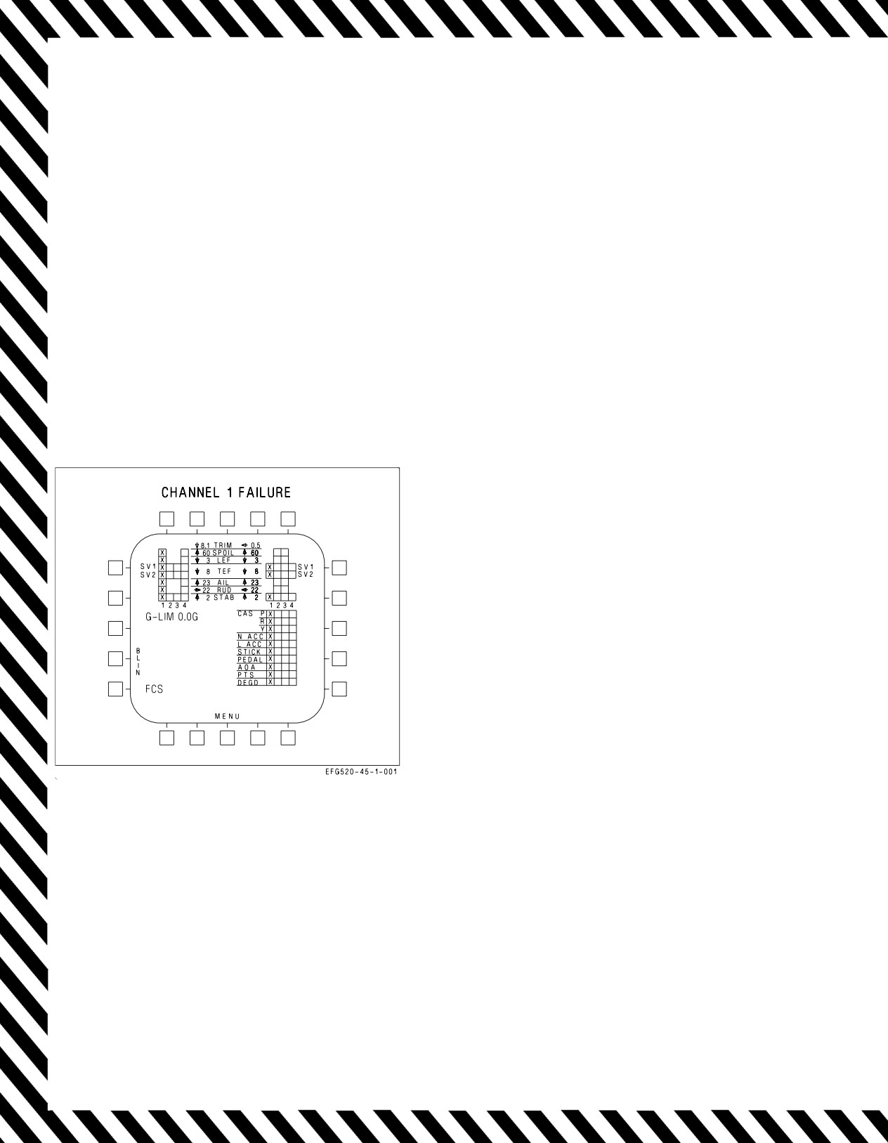
A1-E18GA-NFM-000
15.16 FCS FAILURE INDICATIONS AND EFFECTS
FCS failures are indicated by various cautions and by FCS format Xs and BLIN codes. Following
display or annunciation of an FCS caution, the FCS format should be used to identify the exact
malfunction/failure.
With the failure of FCC channels 1 and 3, the FCS format displays the word INVALID in place of
the G-LIM advisory. Subsequent FCS failures or resets will not be displayed.
The following figures depict typical FCS failure indications and their effects for the majority of FCS
related malfunctions/failures.
EFFECTS:
Loss of speedbrake function.
Figure 15-9. FCS Failure Indications and
Effects
V-15-22
ORIGINAL
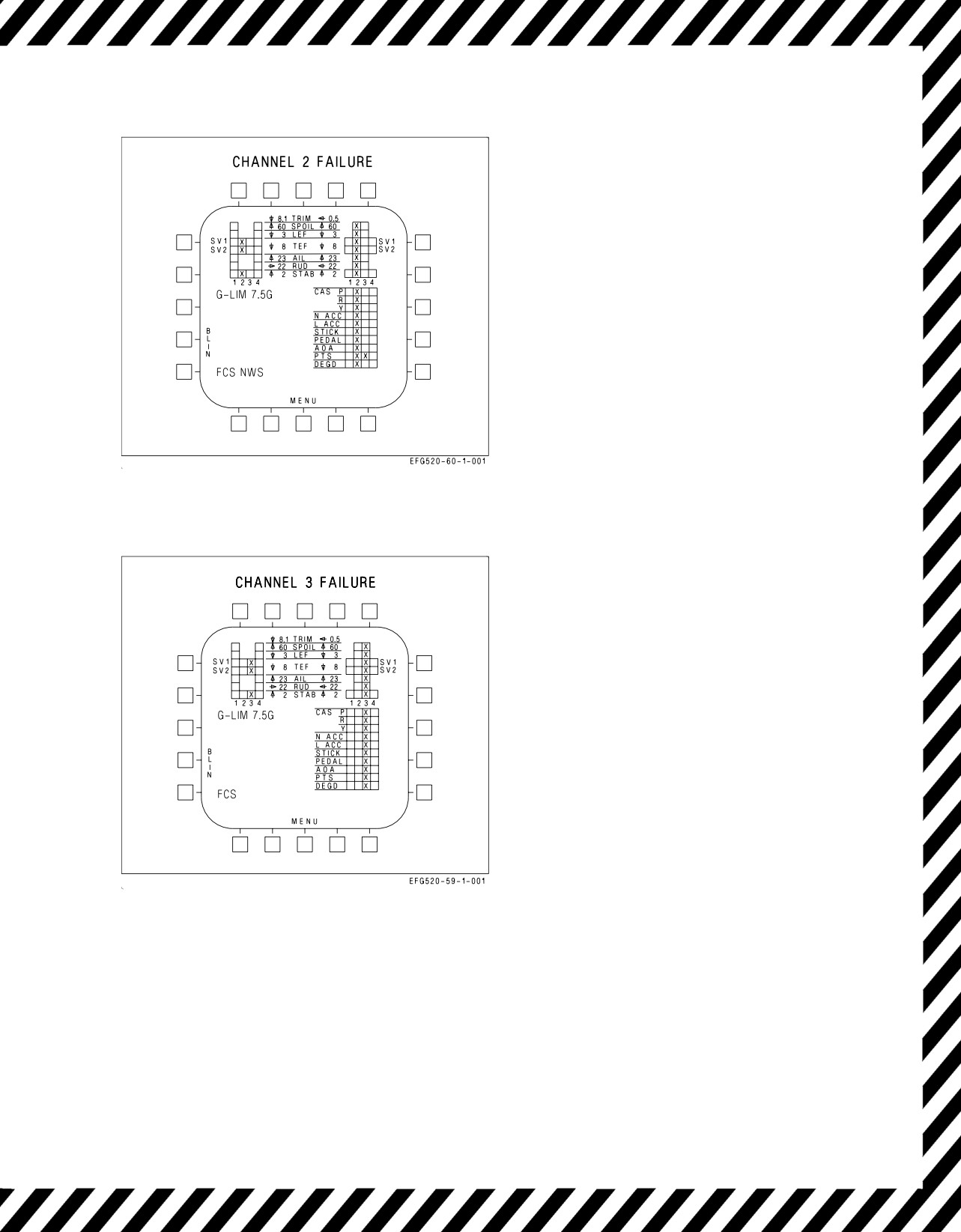
A1-E18GA-NFM-000
EFFECTS:
ATC inoperative.
Normal NWS inoperative.
Loss of HUD barometric altitude (radar altitude
available below 5,000 feet).
Standby altimeter available.
Loss of IFF altitude reporting.
Loss of speedbrake function.
Loss of Air Data from right pressure transmitter
set (PTS)
Loss of AOA/yaw rate warning tone.
Autopilot pitch mode defaults to FPAH if BALT
or RALT were previously selected.
MAD sensor data lost.
Figure 15-10. FCS Failure Indications and
Effects - Channel 2
EFFECTS:
Loss of speedbrake function.
Figure 15-11. FCS Failure Indications and
Effects - Channel 3
V-15-23
ORIGINAL
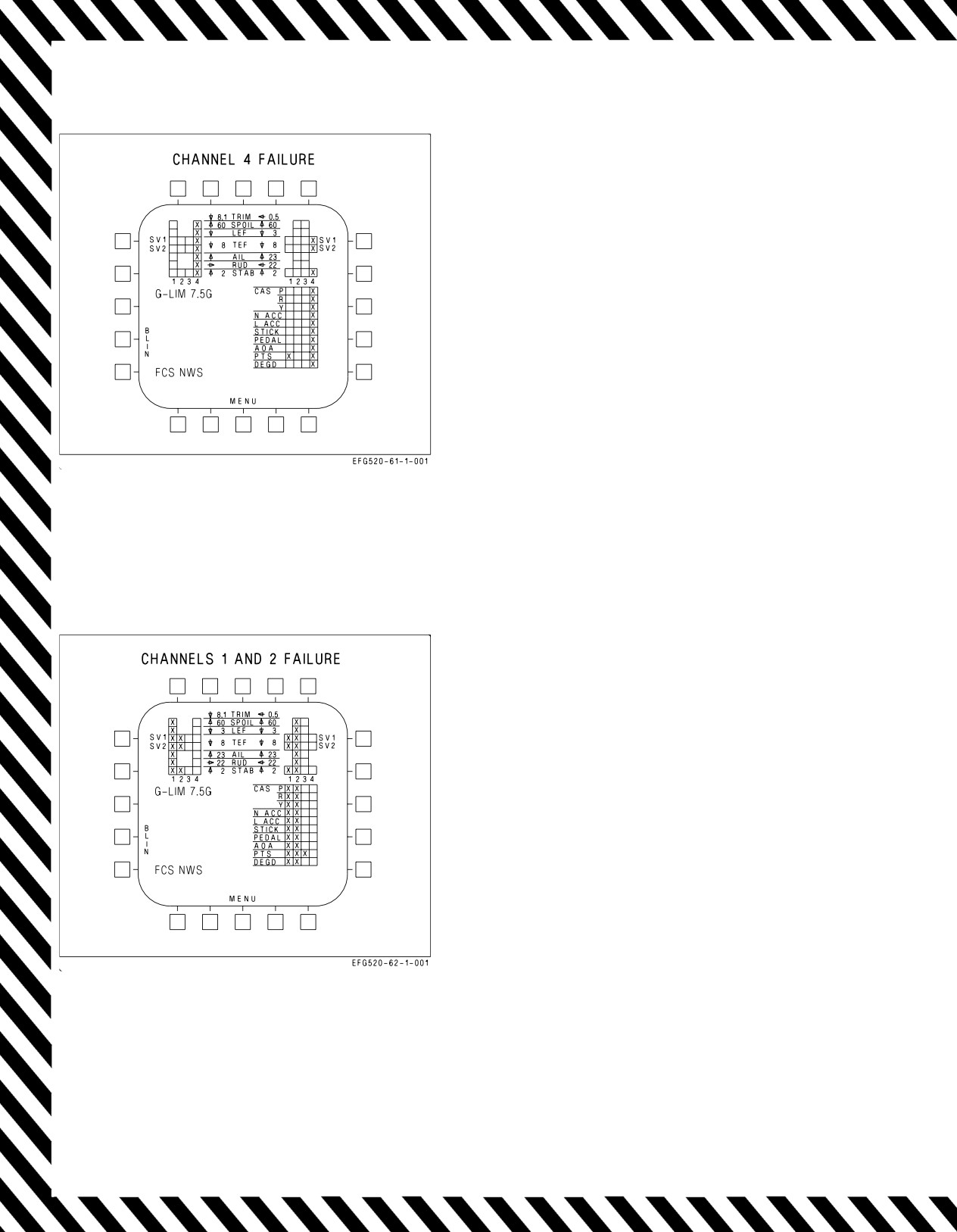
A1-E18GA-NFM-000
EFFECTS:
ATC inoperative.
Normal NWS inoperative.
Loss of Air Data from left pressure transmitter
set (PTS)
Loss of AOA approach/indexer lights.
Loss of speedbrake function.
Loss of AHRS over temperature detection.
Figure 15-12. FCS Failure Indications and
Effects - Channel 4
EFFECTS:
ATC inoperative.
Autopilot inoperative.
Normal NWS inoperative.
Loss of Air Data from left pressure transmitter
set (PTS)
Loss of HUD barometric altitude (radar altitude
available below 5,000 feet).
Standby altimeter available.
Loss of IFF altitude reporting.
Loss of speedbrake function.
MAD sensor data lost.
Figure 15-13. FCS Failure Indications and
Effects - Channels 1 and 2
V-15-24
ORIGINAL
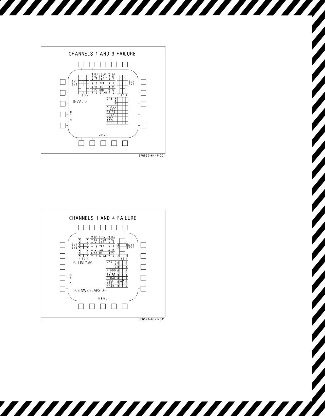
A1-E18GA-NFM-000
NOTE
A simultaneous failure of channels 1
and 3 prevents the display of any
FCS cautions. The FCS display shows
the word INVALID. Use FCES light
to monitor FCS failures.
EFFECTS:
Autopilot inoperative.
Loss of HUD air data displays.
Roll rate limiting is failed. Use no more than ½
lateral stick with rate limited stores aboard.
FCS G-limiter defaults to 7.5g.
Degraded flying qualities
>20° in AUTO
FLAPS.
Use no more than ±15° bank when selecting
HALF or FULL FLAPS from AUTO
FLAPS.
Loss of speedbrake function.
Figure 15-14. FCS Failure Indications and
Effects - Channels 1 and 3
EFFECTS:
FLAP SCHED caution is not displayed.
Left probe AOA blanked from FCS status page.
Autopilot inoperative.
ATC inoperative.
Normal NWS inoperative.
Left leading edge flap locked in failed position.
Left aileron and left rudder failed
(flutter
damper).
Left spoiler.
Loss of Air Data from left pressure transmitter
set (PTS)
Flaps - AUTO:
Loss of speedbrake function.
Flaps freeze.
Flaps - HALF or FULL:
Right leading edge flap frozen.
Trailing edge flaps 30° or 40° maximum.
Scheduled with airspeed.
Figure
15-15. FCS Failure Indications and
No aileron droop.
Effects - Channels
1 and 4
No rudder toe-in.
Loss of AOA approach/indexer lights.
Loss of AHRS over temperature detection.
V-15-25
ORIGINAL
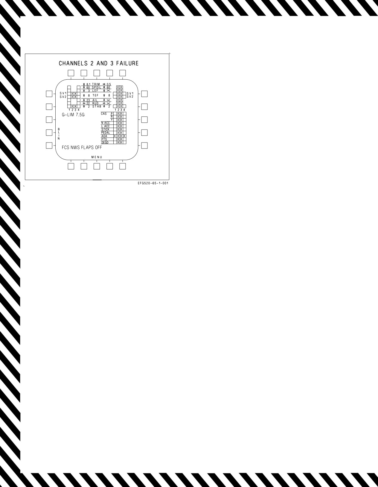
A1-E18GA-NFM-000
EFFECTS:
Right probe AOA blanked from FCS status page.
Autopilot inoperative.
ATC inoperative.
Normal NWS inoperative.
Right leading edge flap locked in failed position.
Right aileron and right rudder failed
(flutter damper).
Standby altimeter available.
Loss of IFF altitude reporting.
Loss of AOA/yaw rate warning tone.
MAD sensor data lost.
Flaps - AUTO:
TEFs will not schedule with AOA but operate
differentially for roll.
Loss of speedbrake function.
Flaps - HALF or FULL:
Left leading edge flap frozen.
Trailing edge flaps 30° or 40° maximum.
Scheduled with airspeed.
Figure
15-16. FCS Failure Indications and
No aileron droop.
Effects - Channels
2 and 3
No rudder toe-in.
V-15-26
ORIGINAL