HELICOPTER, ATTACK, AH-64D LONGBOW APACHE. TECHNICAL MANUAL (2002) - page 4
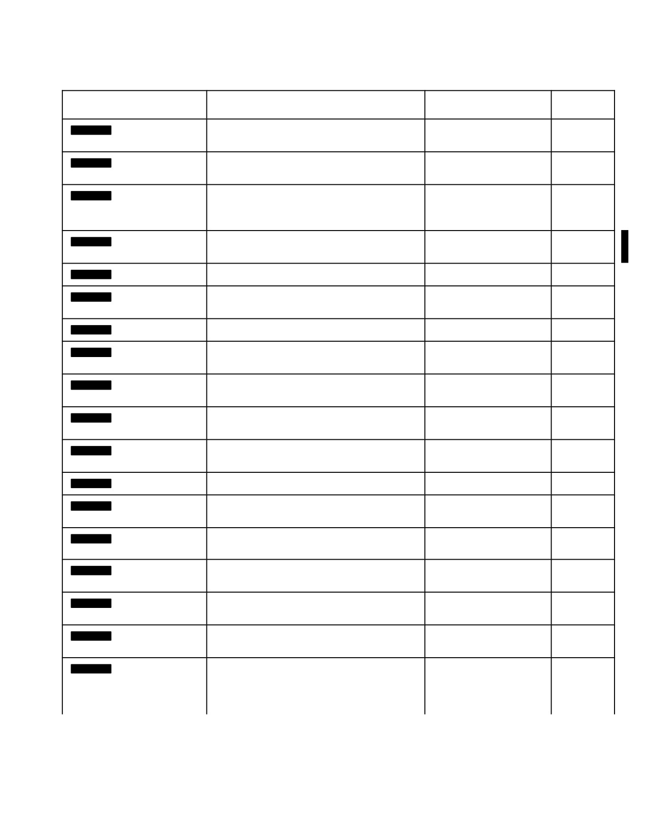
TM 1-1520-251-10
Table 2-15. Advisory Messages - continued
UFD TEXT
PARAMETER OR FAULT
MPD PAGE TEXT
ADVISORY
EUFD TEXT
TONE
[
BLK 2
NET JOIN
A mismatch has been detected and a NET
NET JOIN REQUIRED
NO
REQUIRED]
JOIN is required.
[
BLK 2
IDM INHIBIT]
The IDM has been placed in the INHIBIT
IDM INHIBIT
NO
mode.
[
BLK 2
IDM FAULT]
The IDM has lost communication over the
IDM FAULT
NO
RS232 CSMA port with one or both of the
FM radios.
[
BLK 2
SEEKING TI]
A radio is tuned to the Internet protocol and
SEEKING TI
NO
is attempting to find the TI server.
[
BLK 2
*FREE TEXT]
The IDM has received a flash free message.
*FREE TEXT
YES
[
BLK 2
*FCR TGT
The IDM has received a flash FCR Target(s)
*FCR TGT REPORT
YES
REPORT]
report.
[
BLK 2
*BDA REPORT]
The IDM has received a flash BDA report.
*BDA REPORT
YES
[
BLK 2
*PP REPORT]
The IDM has received a flash manually sent
*PP REPORT
YES
Present Position report.
[
BLK 2
*OBSERVER
The IDM has received a flash oberver
*OBSERVER MSN
YES
MSN UPDT]
mission update.
UPDT
[
BLK 2
*MSG TO
The IDM has received a flash message to
*MSG TO OBSERVER
YES
OBSERVER]
oberver message.
[
BLK 2
*AIRBORNE FIRE
The IDM has received a flash airborne fire
*AIRBORNE FIRE MSN
YES
MSN]
mission message.
[
BLK 2
*SPOT REPORT]
The IDM has received a flash spot report.
*SPOT REPORT
YES
[
BLK 2
*SITREP]
The IDM has received a flash situation
*SITREP
YES
report.
[
BLK 2
*FIELD
The IDM has received flash field orders.
*FIELD ORDERS
YES
ORDERS]
[
BLK 2
*INFO
The IDM has received a flash information
*INFO REQUEST
YES
REQUEST]
request.
[
BLK 2
CPG UFD HOT]
The CPG’s Up - front Display has detected
CPG UFD HOT
NO
an overtemperature condition.
[
BLK 2
PLT UFD HOT]
The Pilot’s Up - front Display has detected an
PLT UFD HOT
NO
overtemperature condition.
[
BLK 2
CTR TANK
The Internal Auxiliary Fuel System is empty.
CTR TANK EMPTY
NO
EMPTY]
The calculated IAFS fuel level is low and
when the IAFS was commanded to transfer,
the fuel lines did not pressurize.
Use or disclosure of this information is subject to the restriction(s) on the title page of this document.
Change 4
2-161
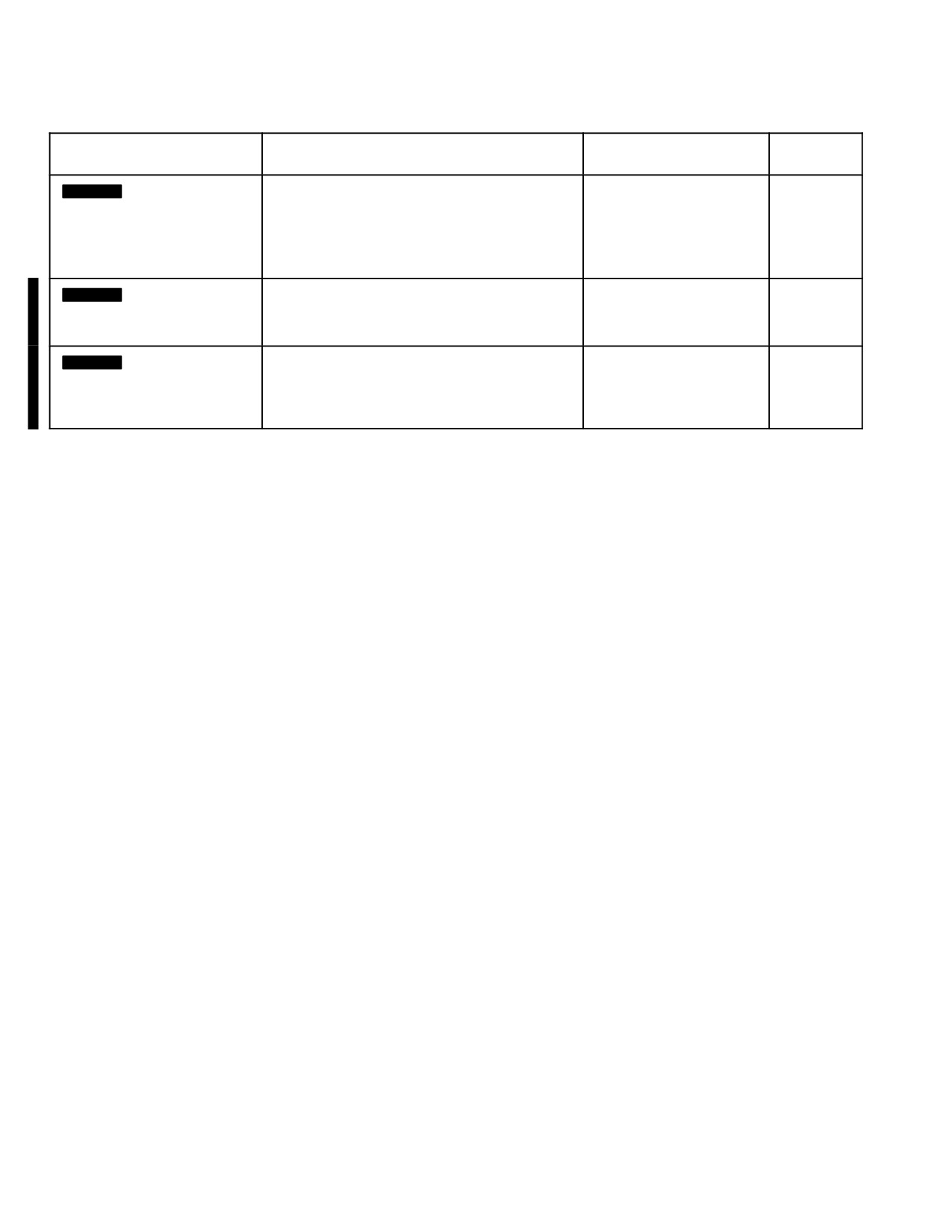
TM 1-1520-251-10
Table 2-15. Advisory Messages - continued
UFD TEXT
PARAMETER OR FAULT
MPD PAGE TEXT
ADVISORY
EUFD TEXT
TONE
[
BLK 2
CTR XFER FAIL]
The Internal Auxiliary Fuel System failed to
CTR XFER FAIL
NO
transfer fuel. The calculated IAFS fuel level
is not low and when the IAFS was
commanded to transfer, the fuel lines did not
pressurize.
[
BLK 2
DTC WRITING]
The DTU door has been opened, but the
DTC WRITING
NO
DTU is finishing writing the FAT on the DTC.
The DTC cards should not be removed.
[
BLK 2
DTC WRITE
The DTU door has been opened, and the
DTC WRITE
NO
COMPLETE]
DTU has finished writing the FAT on the
COMPLETE
DTC. The advisory indicated the DTC cards
ready to be removed.
Use or disclosure of this information is subject to the restriction(s) on the title page of this document.
2-162
Change 2
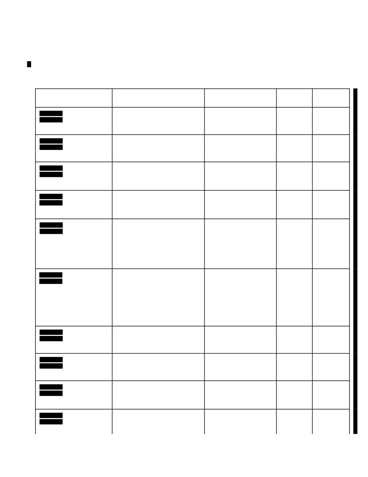
TM 1-1520-251-10
2.140 TESS ADVISORY MESSAGES
mesages. A listing of Advisories, cause for the Advisory,
Advisory Tone, and Voice Message is presented in Table
TESS advisory messages are presented to crewmembers
2-16.
via the UFD/EUFD and MPD Page formats and as voice
Table 2-16. TESS Advisory Messages
UFD TEXT
PARAMETER OR FAULT
MPD PAGE TEXT
ADVISORY
VOICE
EUFD TEXT
TONE
MESSAGE
[
BLK 1
TESS NO GPS]
TESS has not been able to track
TESS NO GPS TRACK
NO
[
BLK 2
TESS NO GPS
the GPS satellites.
TRACK]
[
BLK 1
SIM KILL]
TESS has detected a simulated
TESS SIM KILL
NO
You have
[
BLK 2
TESS SIM
kill condition.
been killed.
KILL]
[
BLK 1
SIM HIT]
TESS has detected a simulated
TESS SIM HIT
NO
You have
[
BLK 2
TESS SIM HIT]
hit condition. Remains on for 8
been hit.
seconds.
[
BLK 1
SIM MISS]
TESS has detected a simulated
TESS SIM NEAR MISS
NO
Near miss.
[
BLK 2
TESS SIM
near miss condition. Remains on
NEAR MISS]
for 8 seconds.
[
BLK 1
SIM RESET]
TESS has established the
TESS SIM RESET
NO
Simulation
[
BLK 2
TESS SIM
aircraft in a reset state after a
is reset.
RESET]
simulated hit or kill condition (i.e.
the aircraft is in the same state it
began the excercise in).
Remains on for 8 seconds.
[
BLK 1
SIM RESURR]
TESS has established the
TESS SIM
NO
Simulation
[
BLK 2
TESS SIM RES-
aircraft in a resurrected state
RESSURRECT
is
SURRECT]
after a simulated hit or kill
resurrected.
condition (i.e. the aircraft is in
the same state before being hit
or killed). Remains on for 8
seconds.
[
BLK 1
LIVE ROUND]
TESS has determined live gun
TESS LIVE GUN AMMO
NO
[
BLK 2
TESS LIVE
ammo is present on the aircraft.
GUN AMMO]
[
BLK 1
LIVE ATAM]
TESS has determined a live ATA
TESS LIVE ATA MSL
NO
[
BLK 2
TESS LIVE ATA
missile is present on the aircraft.
MSL]
[
BLK 1
LIVE HF MSL]
TESS has determined a live
TESS LIVE HF MSL
NO
[
BLK 2
TESS LIVE HF
hellfire missile is present on the
MSL]
aircraft.
[
BLK 1
LIVE ROCKET]
TESS has determined a live
TESS LIVE ROCKET
NO
[
BLK 2
TESS LIVE
rocket is present on the aircraft.
ROCKET]
Use or disclosure of this information is subject to the restriction(s) on the title page of this document.
Change 2
2-163

TM 1-1520-251-10
Table 2-16. TESS Advisory Messages - continued
UFD TEXT
PARAMETER OR FAULT
MPD PAGE TEXT
ADVISORY
VOICE
EUFD TEXT
TONE
MESSAGE
[
BLK 1
TESS STORES]
TESS has found a stores
TESS STORES ERROR
NO
[
BLK 2
TESS STORES
conflict. The configuration load
ERROR]
simulated by the TESS system
does not match a possible
aircraft configuration.
TESS FAIL
TESS has detected a fault
TESS FAIL
NO
condition that will inhibit
operation of the TESS weapon
emulation. Remains on until the
DMS page is displayed.
TESS FAULT
TESS has detected a fault
TESS FAULT
NO
condition that degrades, but
does not inhibit the TESS
weapon emulation. Remains on
until the DMS page is displayed.
Use or disclosure of this information is subject to the restriction(s) on the title page of this document.
2-164
Change 2
TM 1-1520-251-10
CHAPTER 3
BLK 1
AVIONICS
Section I.
GENERAL
3.1 DESCRIPTION
• The UHF-AM (ARC-164) radio provides
the second best overall performance. Two
Avionics equipment includes communication equipment
line-of-sight blockages occur with the UHF
and navigation equipment. This chapter describes each
radio that completely block reception and
major item with respective locations on the airframe and
transmission due to pylon-mounted weap-
antenna locations.
ons. These blockages are in 25-degree di-
3.2 AVIONICS EQUIPMENT CONFIGURATION
rectional arcs, from 012 to 037 degrees and
Communication/Navigation equipment configurations are
from 323 to 348 degrees from the nose. A
shown in Table 3-1. Communication/Navigation antenna
slight range and audibility degradation oc-
locations are shown in Figure 3-1.
curs around the tail directions from 120 to
240 degrees from the nose. Although trans-
3.3 AVIONICS POWER SUPPLY
missions are clear, the maximum reception
range for UHF is approximately 30 NM be-
CAUTION
low 300 MHz and approximately 35 NM
Uncommanded FM transmissions may occur
above 300 MHz.
during IDM IBIT, FALLBACK, when the CIU
• The FM-1 radio transmits clearly and pro-
circuit breaker is open, or during CIU power-
vides the third best overall performance. A
up. CIU power-up occurs during aircraft pow-
slight range and audibility degradation oc-
er-up and upon CIU circuit breaker reset.
curs at the low and high band of frequen-
Power to operate all of the avionics communication equip-
cies in directions from 120 to 210 degrees
ment is provided by the emergency dc bus. This allows back-
from the nose. Reception is achieved up to
up battery power to be used in case of an aircraft electrical
a maximum range of 29 NM for plain and
failure. External power may also be applied. See Chapter 2,
22 NM for cipher text mode. The exception
Section XI for more information on electrical power supply.
is near 40 and 80 MHz where reception is
achieved to a maximum range of 23 and
NOTE
16.5 NM respectively. Non-line-of-sight re-
• Testing of the aircraft has shown that there
ception is expected to be nonexistent.
may be significant self-generated interfer-
• The FM - 2 radio can transmit clearly at
ence (HF missile launchers, DNS anten-
slightly reduced ranges. A severe reception
nae, MPDs, etc.) and local conditions (ra-
range and audibility degradation occurs on
dio, television stations, public transmitters)
most frequencies compared to the FM-1.
that affect aircraft communications receiv-
The maximum line-of-sight reception
ers. Reception ranges may be significantly
range is 22 NM, except for frequencies of
reduced, whereas, transmission capability
32, 40 and 80 MHz that can be as low as
is normally unaffected.
13 NM.
• The VHF-AM (ARC-186) radio can
transmit clearly. A slight range and audi-
bility degradation occurs at the high band
frequencies in directions from 0 to 120
degrees from the nose. Reception is
achieved up to a range of 22 NM except
with frequencies above 145 MHz where
the direction degradation is severe.
Use or disclosure of this information is subject to the restriction(s) on the title page of this document.
Change 3
3-1
TM 1-1520-251-10
Table
3-1. Communication/Navigation Equipment
Control
Equipment
Nomenclature
Use
Range
Location
Remarks
Inter -
Communication
Pilot right
Pilot volume controls RH
Inter-
Within crew
communication
Control Panel
console and
wing volume, CPG
communication
stations
(COMM)
CPG right
volume controls LH wing
between crew
and two
console
volume,
members, wing
external
station
receptacles
communications
located on
and volume control.
the wing
tips.
Radio set
Two-way voice
Line of
MPD, UFD,
VHF-AM
RT-1300B/
communications
sight
and COMM
Communication
ARC-186(V)
VHF-AM frequency
panel
VHF
range 116 to
151.975 MHz.
Receives only
frequency range
108 to 115.975
MHz.
UHF-AM
Radio set
Two-way voice
Line of
MPD, UFD,
Provides the capability to
Communication
RT-1145F/
communication
sight
and COMM
monitor the guard
ARC-164(V)
UHF-AM frequency
panel
frequency while receiving
UHF (HAVE
range of 225 to
and transmitting on any
QUICK)
399.975 MHz.
frequency other than 243
Radio set
Contains a
MHz. Provides the
RT-1614 (HQ2)
separate dedicated
capability for frequency
guard receiver
hopping (FH) and secure
fixed-tuned to 243
communications.
MHz.
VHF-FM
Radio set
Two-way voice
Line of
MPD, UFD,
Provides the capability for
Communication
RT-1478D/
communication
sight
and COMM
FH and secure
ARC-201D VHF
VHF-FM in the
panel
communications.
Single Channel
frequency range of
Ground and
30 to 87.975 MHz.
Airborne Radio
Set
(SINCGARS)
HF
Radio set
Two-way voice
Non - Line
MPD, EUFD,
Provides the capability for
Communication
ARC-220 HF
communication HF
of sight
and COMM
non - line of sight
in the frequency
panel
communications.
range of
20 to 29.9999 MHz.
Use or disclosure of this information is subject to the restriction(s) on the title page of this document.
3-2
Change 3
TM 1-1520-251-10
Table 3-1.
Communication/Navigation Equipment - continued
Control
Equipment
Nomenclature
Use
Range
Location
Remarks
Voice Security
TSEC/KY-58
Secures
Not
MPD, UFD,
The COMSEC subsystem
System
(CIPHER
communication for
applicable
and
provides control of the
DEVICE)
UHF radio.
EMERGENCY
TSEC/KY-58 from both
panel.
crew stations. It has the
capability to store up to 6
Crypto Net Variables.
FM amplifier
Improved FM
Varies power
Not
MPD
Is a variable power
(IFM)
output of FM1.
applicable
amplifier capable of
providing RF output at
four power levels.
Transponder set
RT-1836/
Transmits a reply
Line of
MPD, EUFD,
Includes mode S growth
APX-118(V)
coded to a radar
sight
and
provisions and embedded
interrogator
EMERGENCY
encrypted Mode 4
system.
panel.
operation.
Transponder set
RT-1471/
Transmits a reply
Line of
MPD, EUFD,
Optional installation to
APX-100(V)
coded to a radar
sight
and
RT1836/APX - 118
interrogator
EMERGENCY
system.
panel.
Identification
Kit-1C computer
Provides encrypted
Not
Not applicable
Not reguired for
Friend or Foe
mode 4 operation.
applicable
RT1836/APX - 118
(IFF)
Communication
CIU
Provides
Not
Not applicable
Provides audio switching,
Interface Unit
P/N
centralized
applicable
conditioning, and mixing
7-513200010
processing and
capabilities; crew monitor
distribution of
and transmitter
communication
selections; and voice
data and audio
messages and warning
signals.
tones.
Improved Data
Provides an
Not
MPD
IDM, MD-1295/A
Provides capability to
Modem
interface between
applicable
transmit and receive data
tactical aircraft
via Longbow Protocol.
radios and data
bus.
Use or disclosure of this information is subject to the restriction(s) on the title page of this document.
Change 3
3-3

TM 1-1520-251-10
Table 3-1.
Communication/Navigation Equipment - continued
Control
Equipment
Nomenclature
Use
Range
Location
Remarks
Embedded
GPS
Provides position
Not
MPD
Global
and velocity
applicable
Positioning
information to the
Inertial
INU
Navigation
System (EGI)
INU
Provides
Not
MPD
acceleration,
applicable
angular rate,
heading, velocity,
position, and
position error
estimates data.
Provides actual
0 - 1428 ft
MPD/IHADSS
Radar Altimeter
Altimeter, Radar
terrain clearance
AN/APN-209
height.
Doppler Radar
AN/ASN-157
Provides aircraft
Not
MPD
Velocity Sensor
referenced ground
applicable
(DRVS)
velocities to the
EGI.
ADS
Not
Not applicable
Air Data System
Computes air mass
applicable
referenced data to
provide the
Omni-directional
airspeed,
Barometric Altitude,
and Outside Air
Temperature
information
necessary to
display Mean Sea
Level (MSL) terrain
elevation for the
aircraft present
position.
Automatic
AN/ARN-149
Provides a relative
Line of
MPD
Direction Finder
bearing to the
sight
(ADF)
station signal as
well as an audio
output of the
received signal.
Use or disclosure of this information is subject to the restriction(s) on the title page of this document.
3-4
Change 3
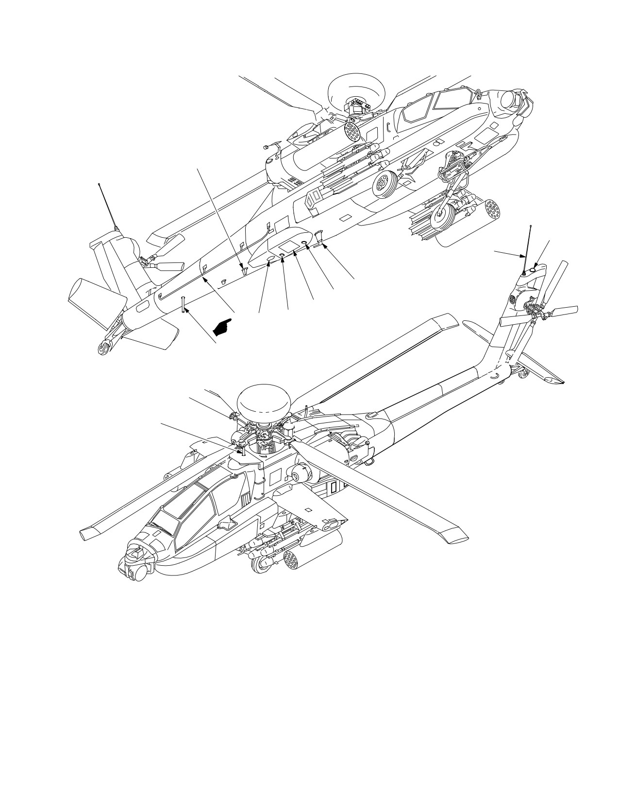
TM 1-1520-251-10
1
3
2
8
7
6
11
5
9
10
4
1. UHF
6. RADAR DOPPLER
2. VHF−AM/FM1 WHIP
7. RADAR ALTIMETER RECEIVER
3. GLOBAL POSITIONING SYSTEM (GPS)
8. VHF−FM2
4. UPPER TRANSPONDER
9. ADF
5
RADAR ALTIMETER (TRANSMITTER)
10. LOWER TRANSPONDER
11. HF
LBA5082
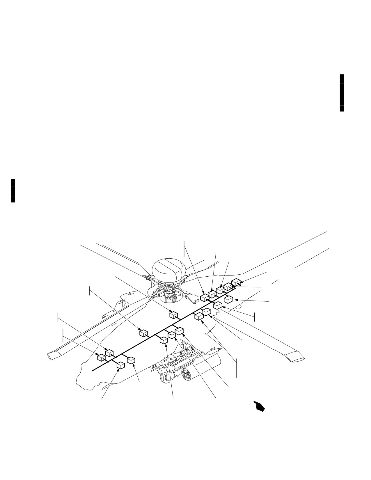
Figure 3-1. Communication/Navigation Antennas
Use or disclosure of this information is subject to the restriction(s) on the title page of this document.
Change 3
3-5
TM 1-1520-251-10
Section II. COMMUNICATIONS SUBSYSTEM
3.4 INTRODUCTION
• ARC-186(V) VHF-AM Radio Set
NOTE
This section covers the description and operation of air-
craft communication subsystem and the Transponder/IFF
The APX-100(V) Transponder or
subsystem (fig 3-2 ). Both voice and digital communica-
APX-118(V) may be installed. If
tions are supported by the following equipment:
APX - 100(V) is installed, Kit - 1C computer
must be installed for Mode 4 operation.
• ARC-186(V) VHF-AM Radio Set
• ARC-164(V) UHF-AM Radio Set (HAVEQUICK)
Each crewstation provides the crew with independent control
and status monitoring of the communication subsystem via
• Load Maintenance Panel (LMP) (COMSEC)
the Multipurpose Display (MPD), Up Front Display (UFD),
• ARC-201D VHF-FM (SINCGARS) 2 each
and Keyboard Unit (KU). In addition, monitor select and vol-
• TSEC/KY-58 (CIPHER DEVICE)
ume/squelch controls for each of the four radios are con-
trolled by the COMM panel in each crewstation. The commu-
• IFM-101A/AM-7189A/ARC Improved FM (IFM)
nication subsystem equipment is powered from the battery
Amplifier
bus and defaulted to ON when power is applied. However
crew control of the radios is limited until aircraft or external
• APX-100(V) Transponder
power is applied. After aircraft power has been applied to the
or
MPDs, rapid initialization of the radio presets and Signal Op-
• APX-118(V) Transponder
erating Instructions (SOI) can be accomplished via the Data
• MD-1295/A Improved Data Modem (IDM)
Transfer Unit (DTU).
AM1789A/ARC
ARC−186
IMPROVED FM
VHF−AM RADIO
AMPLIFIER
ARC−201D (FM2)
VHF−FM RADIO
SYSTEM
PROCESSOR q2
HF POWER AMPLIFIER
COUPLER
ARC−201D (FM1)
DATA TRANSFER
UNIT
VHF−FM RADIO
ARC220 HF RADIO
DISPLAY
ARC−164
PROCESSOR q2
UHF−AM RADIO
COMMUNICATION
INTERFACE
UNIT (CIU)
KY−58/TSEC
PROCESSOR
SECURE VOICE
KY−100/TSEC
PROCESSOR
SECURE VOICE / DATA
KIT−1C/TSEC
MD1295/A
IMPROVED DATA
TRANSPONDER
MODEM (IDM)
COMPUTER (WITH APX100)
SYSTEM
DISPLAY
APX−100(V) OR APX118(V)
PROCESSOR q1
PROCESSOR q1
IFF TRANSPONDER
LBA5080A
Figure 3-2. Communications Subsystem
Use or disclosure of this information is subject to the restriction(s) on the title page of this document.
3-6
Change 3
TM 1-1520-251-10
3.5 ARC-186(V) VHF-AM RADIO SET
3.6.1
Frequency Hopping (FH) Capability (HAVE
QUICK). The UHF radio has a FH capability, which is an
electronic counter-countermeasures (ECCM) enhance-
The aircraft contains one ARC-186 VHF radio which pro-
ment to the standard UHF radio. The radio provides a FH
capability, by which the frequencies being used and the
vides two-way communication over VHF-AM frequency
dwell times are rapidly changed many times a second.
range (116.000 to 151.975 MHz) in 0.025 MHz channel
The radio requires three items to determine the FH pat-
spacing.
tern:
a. Time of Day (TOD). The TOD is synchronized to
NOTE
the radio clock, which is normally set to Coordinated Uni-
versal Time (UTC). The TOD is required by the radio to
ARC-186 FM frequencies (30.000 to
maintain its internal clock, which controls the FH timing.
87.975 MHz) are not implemented in the air-
The TOD is set upon power-up using the time from the
craft. FM frequencies are provided by the
EGI. The crew may send or receive the TOD signal if FH
ARC-201D radios.
communication is desired through non TOD synchronized
radios. Receiving the TOD affects only the internal clock
of the UHF radio.
3.5.1 VHF Tone. Selecting the VHF TONE button will
not generate a tone from the radio but will transmit a ”dead
b. Word of Day (WOD). The WOD is classified and
carrier” over the air for maintenance.
controlled by the National Security Agency (NSA). The
WOD programs the FH pattern and rate. The radio cannot
function in the FH mode without a valid WOD. A WOD is
3.6 ARC-164(V) UHF-AM RADIO SET (HAVE QUICK)
required for each day and consists of up to six segments,
which code the radio for FH. For HaveQuick 2 radios, the
WOD must be tagged with its operational day (1-31). The
The aircraft contains one ARC-164 UHF radio which pro-
WODs are loaded into the radio through the DTU or via
vides two-way communications over UHF-AM frequency
the crew.
range (225.000 to 399.975 MHz) in 0.025 MHz channel
spacing. The radio contains a separate dedicated guard
c. Net Number. The net number programs the radio
receiver fixed tuned to 243.000 MHz, thus providing capa-
to operate in one of the FH modes, selects the frequency
bility to simultaneously monitor guard frequency (243.000
table to be used and determines entry point into the FH
MHz) while receiving and transmitting on any frequency
pattern. Net numbers enable multiple station pairs to op-
other than 243.000 MHz. When the transceiver is tuned to
erate simultaneously using the same WOD and TOD with-
243.000 MHz, the dedicated guard receiver is automati-
out interference. The net number will be loaded into the
cally turned OFF. The radio set has squelch capability and
radio through the DTU or via the crew.
can operate in either single channel or frequency hopping
mode. The frequency hopping capability of the UHF radio
3.6.2 UHF Tone. Selecting the UHF TONE button gen-
is referred to as HAVE QUICK (HQ). There can be one of
erates an audio tone from the radio and transmits the tone
two versions of HAVE QUICK radios installed in the air-
over the air.
craft. HAVE QUICK 1 radios provide the capability to load
one word of day into the radio and utilize 6 training fre-
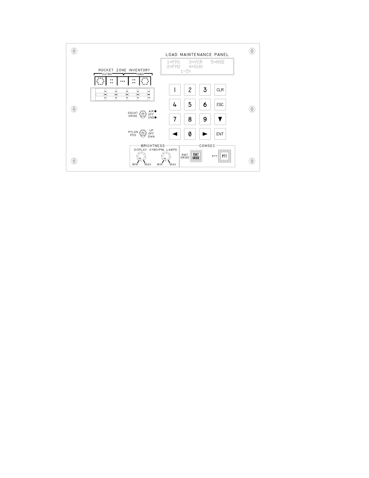
3.7 LOAD MAINTENANCE PANEL (LMP)
quencies for the training mode. HAVE QUICK 2 radios
provide the capability to load up to six words of the day
The LMP (fig 3-3 ) consists of a keypad, display, front pan-
into the radio and utilize 16 training frequencies for the
el control switches, and knobs. It is co-located in the RH
training mode.
aft avionics bay with the Remote Selectable Fill Port.
Use or disclosure of this information is subject to the restriction(s) on the title page of this document.
3-7
TM 1-1520-251-10
6PD
6IL
6RC
6SK
6WP
LBA2583
Figure 3-3. Load Maintenance Panel
3.7.1 LMP Capabilities. The LMP provides the follow-
3.7.3 Press-To-Talk (PTT) Pushbutton. The PTT but-
ing capabilities:
ton enables the transfers of Crypto Net Variable(s) from
the Fill Gun to the KY-58. This CNV transfer can be initi-
• Display and specify VCR tape length loaded.
ated by keying the appropriate radio from either crewsta-
• Position pylons for loading stores.
tion.
• Override the SQUAT SWITCH setting to simulate
3.7.4 LMP Lighting. To save power, all LMP displays
airborne conditions for troubleshooting and testing
and lamps are extinguished while airborne. After landing,
while on the ground.
activation of any LMP keypad pushbutton reactivates the
• Display and specify rocket types associated with
LMP displays and status lights. The initial keypad push-
each of the aircraft rocket zones.
button activation is not interpreted as a data entry key-
stroke.
• Display and specify 30mm Gun rounds count.
• Display and specify Chaff count.
3.7.5 FM Radio Fill Selections. The LMP provides for
• Specify data download to the FM radios.
frequency hopping and COMSEC variable fill selections
via LMP keyboard. Selections are available for the follow-
• Press-to-talk (PTT) and Remote Override (RMT
ing fill gun capabilities:
ORIDE) COMSEC pushbuttons.
• Single Hopset Preset
3.7.2
Remote Override (RMT ORIDE) Pushbut-
• Single Lockout Set Preset
ton.
The RMT ORIDE button disables MPD control and
enables front panel (KY-58) control capabilities for Crypto
• Single COMSEC variable
Net Variables loading purposes. The RMT ORIDE button
is automatically disabled when the aircraft is airborne and
• Complete set of Hopset/Lockout Set/COMSEC
must be manually actuated on the ground for any further
loading.
Single Hopset/Lockout Set/COMSEC variable filling re-
quires two separate FILL gun devices. A complete set of
NOTE
Hopset/Lockout Set/COMSEC variable filling can be
ICS communication is the only recom-
achieved with a single FILL gun device. LMP display feed-
mended communication during PTT opera-
back is provided for function in-progress, function comple-
tions. Do not use UHF at this time.
tion, function PASS and function FAIL status.
Use or disclosure of this information is subject to the restriction(s) on the title page of this document.
3-8
TM 1-1520-251-10
3.7.6 VCR Selection. Selecting VCR on the LMP top
automatically loaded when the system is filled through the
level menu produces a display which provides a selection
Remote Selectable Fill Port or through an ECCM Remote
for one of two possible VCR tape lengths. In addition, the
Fill (ERF).
currently selected VCR tape length is displayed. Tape
length is used by the VCR to calculate the elapsed time
3.9 TSEC/KY-58 VOICE SECURITY SYSTEM
which is displayed on the VCR page. Two possible tape
lengths are 40 minute and 60 minute tapes.
The aircraft contains one TSEC/KY-58 Voice Security
System for the UHF radio which provides encrypted com-
3.8 ARC-201D VHF-FM SINGLE CHANNEL GROUND
munication for the radio. The TSEC/KY-58 has the capa-
& AIRBORNE RADIO SET (SINCGARS)
bility to store up to six Crypto Net Variables (CNV). CNVs
are COMSEC variables required to establish the encryp-
tion process inside the TSEC/KY-58. CNVs are generally
The aircraft contains two ARC-201D VHF-FM radios
loaded directly into the TSEC/KY-58 via a fill gun by the
which provide two-way communications over VHF-FM fre-
maintenance crew at the Remote Selectable Fill Port, but
quency range of 30.000 to 87.975 MHz in 0.025 MHz
may also be loaded through RF Link. TSEC/KY-58 con-
channel spacing. The radio set operates in either single
trols are implemented on the MPD and/or the EMER-
channel or frequency hopping (FH) mode. The two
GENCY Panel and the LMP.
ARC-201D radios are referred to as FM1 and FM2, or in
general as FM. In addition, secure voice/data communica-
3.9.1
KY-58 Tones. The KY-58 generates tones for
tions are provided by COMSEC equipment which is em-
variable loading and failure conditions. An additional tone
bedded in the radios.
is generated when the KY-58 is ready to Tx or Rx.
3.8.1
Frequency Hopping (FH) Capability. This en-
3.10 IMPROVED FM (IFM)
hancement provides a FH capability (frequencies and
dwell times are rapidly changed many times a second).
FH provides an anti-jamming capability which can operate
CAUTION
in conjunction with a secure communications mode. Zer-
oizing the individual radio can be accomplished from the
• The IFM should be turned OFF when
MPD. Three items required to determine FH patterns are:
operating the radios on battery power
to avoid draining the aircraft battery.
a. Time. Time is in the form: day, hour, and minutes.
• Transmitting IFM in HIGH while both
Time is required by the radio to maintain its internal clock,
FMs are tuned to the same frequency
which controls FH timing.
may cause damage to the FM2 receiv-
er.
b. Hopset. The Hopset is classified and controlled
by the NSA. The Hopset programs frequency hopping
NOTE
rate and frequency hopping pattern. The range of Hopsets
is between 001 to 999. There are up to six Hopsets loaded
Failure of the IFM will turn off the sidetone
into the radio. Hopset information can be inserted locally
from the ARC-201D FM1 radio. An IFM fail-
through the fill gun with control provided by the load main-
ure is also reported during radio IBIT. The
tenance panel (LMP) and connected via the remote se-
FM1 radio may still be able to transmit at its
lectable FILL port. It can also be distributed by RF link
own internal power of 10 Watts. Should an
also known as ECCM Remote Fill (ERF).
IFM failure occur it is recommended to turn
IFM off.
c. Lockout Set. During frequency selection for the
Hopsets, it may be determined that interference may re-
The aircraft contains one IFM amplifier to vary the RF
sult between two nets using the same frequency. In this
power output of the FM1. The four power levels are listed
case one of two types of lockouts, common or unique, is
in Table 3-2.
Use or disclosure of this information is subject to the restriction(s) on the title page of this document.
3-9
TM 1-1520-251-10
the KIT-1C computer via a fill gun through the Remote Se-
Table 3-2. RF Output Levels
lectable Fill Port in the aft avionics bay. Code selection is
Power Setting
Effective Radiating Power (Watts)
limited to A or B, which corresponds to the operational
LOW
2.5
day. Other MODE 4 capabilities are:
NORM
10.0
• When on the ground, the MODE 4 HOLD
HIGH
40.0
enables the computer to save the last
MODE 4 codes for utilization on the next
OFF
10.0
power-up.
The communications subsystem provides capability to set
• IDENT selection located on the MPD and
IFM Power to LOW /NORMAL /HIGH /OFF via the MPDs.
COMM panel enables IDENT transmis-
sion to ID ownship on others’ radar
screens.
3.11 APX-100 TRANSPONDER
• Selectable MODE 4 audio cueing.
The aircraft contains one transponder, an APX-100 or
APX - 118 (para 3.11A ) which provides automatic radar
• Selectable MODE 4 UFD visual cueing.
identification of the aircraft to all suitably equipped sta-
tions. The transponder receives, decodes, and responds
• Selectable EMERGENCY mode.
to interrogation of the following modes:
3.11A APX-118 TRANSPONDER
MODE 1
Provides 32 possible code
combinations that can be selected
The APX - 118 provides automatic radar identification of
in-flight. Possible code combinations
the aircraft to all suitably equipped stations. The trans-
are: 00-03, 10-13, 20-23, 30-33, 40-43,
ponder receives, decodes, and responds to interrogation
50-53, 60-63, and 70-73.
of the following modes:
MODE 2
Provides 4096 possible code
combinations. The desired code must
MODE 1
Provides 32 possible code
be set on the ground on the APX-100
combinations that can be selected
located behind access panel L160.
in-flight. Possible code combinations
Possible code combinations are
are: 00-03, 10-13, 20-23, 30-33, 40-43,
0000-7777.
50-53, 60-63, and 70-73.
MODE 3/A Provides 4096 possible code
MODE 2
Provides 4096 possible code
combinations that can be selected
combinations. Possible code
in-flight. Possible code combinations
combinations are 0000-7777.
are 0000-7777.
MODE 3/A
Provides 4096 possible code
MODE C Provides altitude information obtained
combinations that can be selected
from the FMC.
in-flight. Possible code combinations
are 0000-7777.
NOTE
MODE 4
Provides a crypto - secure mode of
identification by relying on an encrypted
• KIT - 1C is not required in the aircraft with
interrogation. It utilizes two classified
the APX - 118 transponder.
operational codes which are loaded
directly into the transponder via a fill
• When the KIT-1C is not installed in the
device through the Remote Selectable
aircraft, the MODE 4 selection will not be
Fill Port in the aft avionics bay. Code
shown on the MPDs.
selection is limited to A or B, which
corresponds to the operational day.
3.11.1 KIT-1C MODE 4 Computer. Provides a crypto-
MODE C
Provides altitude information obtained
secure mode of identification for the APX - 100 transpond-
from the FMC.
er, by relying on an encrypted interrogation. It utilizes two
MODE S
Growth provisions only.
classified operational codes which are loaded directly into
Use or disclosure of this information is subject to the restriction(s) on the title page of this document.
3-10
Change 3
TM 1-1520-251-10
3.12 IMPROVED DATA MODEM (IDM)
UFD communications symbology are:
NOTE
1.
Radio identifier (VH, UH, F1, and F2).
Testing has shown that reception ranges are
2.
Currently tuned frequency/FH parameters.
often degraded by five NM or more over
those ranges where voice communication
3.
Squelch (OFF/ON) status (asterisk indicates
can be received.
squelch on).
The IDM provides an interface between aircraft radios and
4.
CALL SIGN assigned to the currently tuned fre-
the mission equipment. IDM communications occur over a
quency.
crewmembers selected radio. Management of the IDM is
performed through the communications subsystem. Baud
5.
Cipher (OFF/ON) status and Crypto Net Vari-
rate options of 16000, 8000, 2400, 1200, 600, 300, 150, or
able (UHF, FM 1, and FM 2 only).
75 are available.
6.
Guard (G) receiver (OFF/ON) (UHF only).
3.13 UP FRONT DISPLAY (UFD) COMMUNICATION
CONTROLS
7.
IDM Net Status.
UFD communication controls are the RTS pushbutton and
8.
Last tuned frequency.
LAST pushbutton.
9.
Current time (Local or Zulu).
3.13.1 RTS Push Button. When the RTS button is ac-
tioned the UFD cycles through the crewmembers selected
10.
FM1 power setting Low (L), Normal (N), High
radios, automatically bringing up the next radio as the ac-
(H), Off (O) Status.
tive transmitter.
11.
XPNDR Mode 4 code. Presence of code indi-
3.13.2 LAST Button. When the LAST button is ac-
cates Mode 4 is ON.
tioned the last frequency shown on the right side of the
UFD is exchanged with current frequency and call sign on
12.
Transponder Master Control (STBY/NORM/
the left side of the display. RTS radios in both crewstations
EMER) status.
are tuned to the last set frequency when the LAST button,
on the radio selected, is actioned.
13.
Transponder Mode 3/A status and code.
3.14 UFD COMMUNICATIONS FORMAT
14.
Transponder identifier.
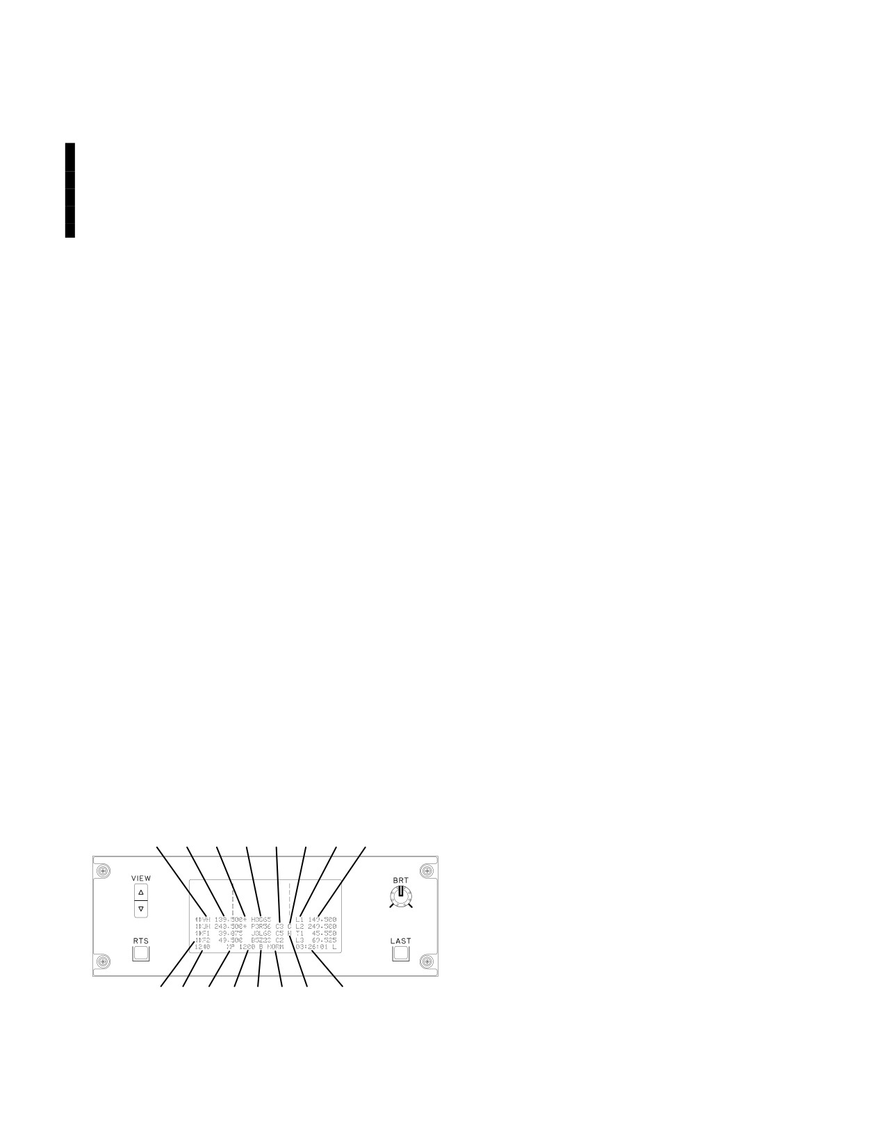
The UFD is capable of displaying a select subset of the
15.
Total fuel quantity.
current status of the communication system as shown in
figure 3-4.
16.
Transmit/receive indicator. Filled triangle indi-
cates radio selected for transmitting. Unfilled
1
2
3
4
5
6
7
8
triangle indicates radio is enabled for monitor-
ing. The opposite crewmembers radio status
triangles are on the right. Lack of a triangle indi-
cates the radio is not being used/monitored (pin
pulled).
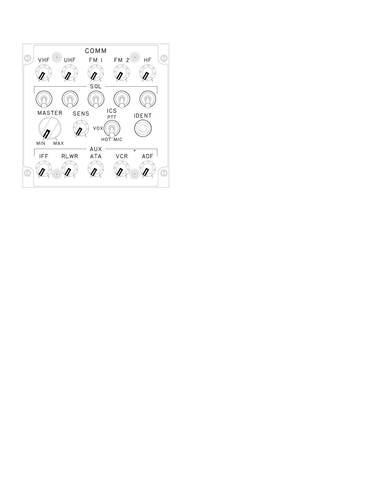
3.15 COMMUNICATIONS PANEL (COMM)
There is a COMM panel (fig 3-5) in both the pilot’s and
16
15
14
13
11
12
10
9
LBA0401
CPG’s crewstation to provide audio level control for the re-
spective crewstation. Following is a description of the
Figure 3-4. UFD Format
COMM panel controls:
Use or disclosure of this information is subject to the restriction(s) on the title page of this document.
Change 3
3-11
TM 1-1520-251-10
3.15.5 ICS Mode Switch. The ICS mode switch pro-
vides selection of the audio keying system for commu-
nication between crew stations. Following are the three
modes that can be selected with the ICS switch:
ÑÑÑÑÑÑÑÑ
ÑÑ
ÑÑ
ÑÑÑÑÑÑÑ
ÑÑ
ÑÑ
a. Push-To-Talk (PTT). The PTT position allows
communication only while the ICS PTT switch is being ac-
tioned.
ÑÑÑ Ñ
b. VOX. The VOX position allows communication
ÑÑÑÑÑÑ
between crewmembers only when their voice levels ex-
ceed the threshold level as set with the SENS control.
ÑÑÑ
ÑÑ
c. HOT MIC. The HOT MIC position allows continu-
ous communication between crewmembers.
ÑÑÑÑÑÑÑÑ
ÑÑ
ÑÑ
ÑÑÑÑÑÑÑÑ
ÑÑ
ÑÑ
3.15.6 IDENT Switch. The IDENT switch allows the
LBA0072
transponder to be placed in IDENT mode. This switch per-
forms the same function as the IDENT option label located
on the MPD XPNDR page.
Figure 3-5. Communications (COMM) Panel
3.15.7 AUX Control IFF.
a. IFF Control. The IFF control provides indepen-
3.15.1 Volume Control The volume control provides
dent volume control of the IFF MODE 4 audio.
independent volume control for the respective radio. Mon-
itoring of the radios, VCR, and ADF audio can be disabled
by pulling out the respective control knob which removes
b. Radar/Laser Warning Receiver (RLWR) Con-
the appropriate monitor status triangle from the UFD, un-
trol. The RLWR control provides independent volume
less selected as the active transmitter.
control of the RLWR audio.
3.15.2 Squelch (SQL) Switches. The SQL switches
c. Air To Air (ATA) Control. This knob is not cur-
are momentary toggle switches that provide squelch se-
rently used.
lect/deselect capability for both crewstations. There is a
SQL switch for each radio, located directly under the cor-
d. Videocassette Recorder (VCR) Control. The
responding radio volume control.
VCR control provides independent volume control of the
VCR playback audio.
3.15.3 MASTER Control. The MASTER control pro-
vides the capability to adjust the audio level of all signals
e. Automatic Direction Finder
(ADF) Con-
associated with the communication subsystem and con-
trol. The ADF control provides independent volume
trols the applicable crewstation helmet and wing connec-
control of the ADF audio.
tion volume levels.
3.16 EMERGENCY PANEL
3.15.4 Sensitivity (SENS) Control. The SENS control
provides the capability to adjust the audio threshold level
when the ICS mode switch is in the VOX position. The
The EMERGENCY panel (fig 3-6) allows selection of the
system only transmits when voice level exceeds the
transponder (XPNDR) emergency mode, tuning the UHF
threshold setting of the SENS adjustment. To increase
radio to the GUARD frequency, and zeroizing classified
sensitivity rotate control clockwise.
data.
Use or disclosure of this information is subject to the restriction(s) on the title page of this document.
3-12
Change 3

TM 1-1520-251-10
g. IDM network parameters.
EMERGENCY EMERG
HYD
h. IDM subscribers team indications in the IDM and
GUARD
XPNDR
ZEROIZE
DP NVM.
ON
ON
ON
i. TSD Waypoints, Targets/Threats, and Control
Measures.
NOTE
LBA2448
• Emergency zeroize does not erase clas-
sified data in the FCR and DTC
Figure 3-6. EMERGENCY Panel
3.17 CYCLIC GRIP COMMUNICATIONS CONTROLS
3.16.1 GUARD Button. Pressing this button tunes the
The cyclic controls provide the crew with the RADIO/ICS
UHF radio to its guard frequency, which is displayed on
Push-To-Talk (PTT) switch and the Radio Transmit Select
the UFD. The crew member pressing the GUARD button
(RTS) switch.
will cause the system to automatically RTS to the UHF ra-
3.18 ICS/RADIO FOOT CONTROLS
dio. Deselecting the GUARD button commands the sys-
tem to load the guard frequency into the last frequency
CS/Radio foot controls are identical for both crew stations
location and places last single channel frequency (and as-
and are located on the forward crew station deck. The ra-
sociated call sign) into the current frequency and call sign
dio PTT foot control is located on the left side of the crew
locations on the UFD.
station. The ICS PTT foot control is located on the right
side of the crew station.
3.16.2
XPNDR Button. Pressing this button sets a
code of 7700 in mode 3/A. The XPNDR Mode 3/A button
3.19 COMMUNICATION SUBSYSTEM DISPLAY
has to be moded ON and XPNDR MASTER button can be
FORMAT OVERVIEW
in NORM or STBY prior to activating the XPNDR emer-
gency button. The UFD provides a status of 7700 EMER
The Communication Subsystem controls and displays are
to indicate that emergency transponder mode has been
accessed through the MPDs in each crew station. The
selected. To exit the emergency transponder mode, press
paging tree (fig 3-7) illustrates the structure of the COM
the XPNDR button again, which will extinguish the light.
subsystem pages.
After deactivation, the system does not reset any codes
3.20 COMMUNICATIONS PROTOCOL
until they are entered manually or with the DTC.
The following communications protocol terminology is
3.16.3 ZEROIZE Switch. The ZEROIZE switch is ac-
used throughout this section:
tioned by first pulling it up and out of the locked position,
• Originator ID. Unique IDM ID that is assigned to
next to the forward position, and then returning the switch
the ownship in the IDM.
to the locked or after position to complete the zeroization
process. Actioning the ZEROIZE switch zeroes-out the
• Network. A network is a functionally related group
following classified data:
of subscribers assigned to a common radio
frequency, digital network, radio, and call sign.
a. COMSEC variables.
• Subscriber. A subscriber is a single member or
station assigned to a network. Each subscriber
b. FM1 and FM2 Hopsets.
has a unique subscriber ID which is stored in their
IDM.
c. FM1 and FM2 lockout sets.
•
Team Member. A team member is a subscriber
designated to receive IDM messages. There can
d. HQ1 WOD or HQ2 MWOD from radio, and SP
only be 15 team members per digital network.
NVM.
• Zone Member. A zone member is a subscriber
e. All Communications Electronic Operating Instruc-
designated to receive zone messages. There can
tions (CEOI) tables/data in DP NVM.
only be 8 zone members (including the ownship)
per digital network. A net member must be a team
f. Mode 4 (KIT-1C).
member in order to be a zone member.
Use or disclosure of this information is subject to the restriction(s) on the title page of this document.
Change 3
3-13
TM 1-1520-251-10
COM
ATHS
MAN
MSG REC
NET
FREE
ATHS
SUFFIX
MODEM
EDIT
TEXT
MSG SEND
SOI
SINC
HQ1/2
XPNDR
UTIL
EXPND
SEG
TSET
FALL BACK
FREE
CURRENT
ERF
ATHS
ERF
ERF
TEXT
MISSION
REC
SEND
Available from Menu Page
LBA2017B
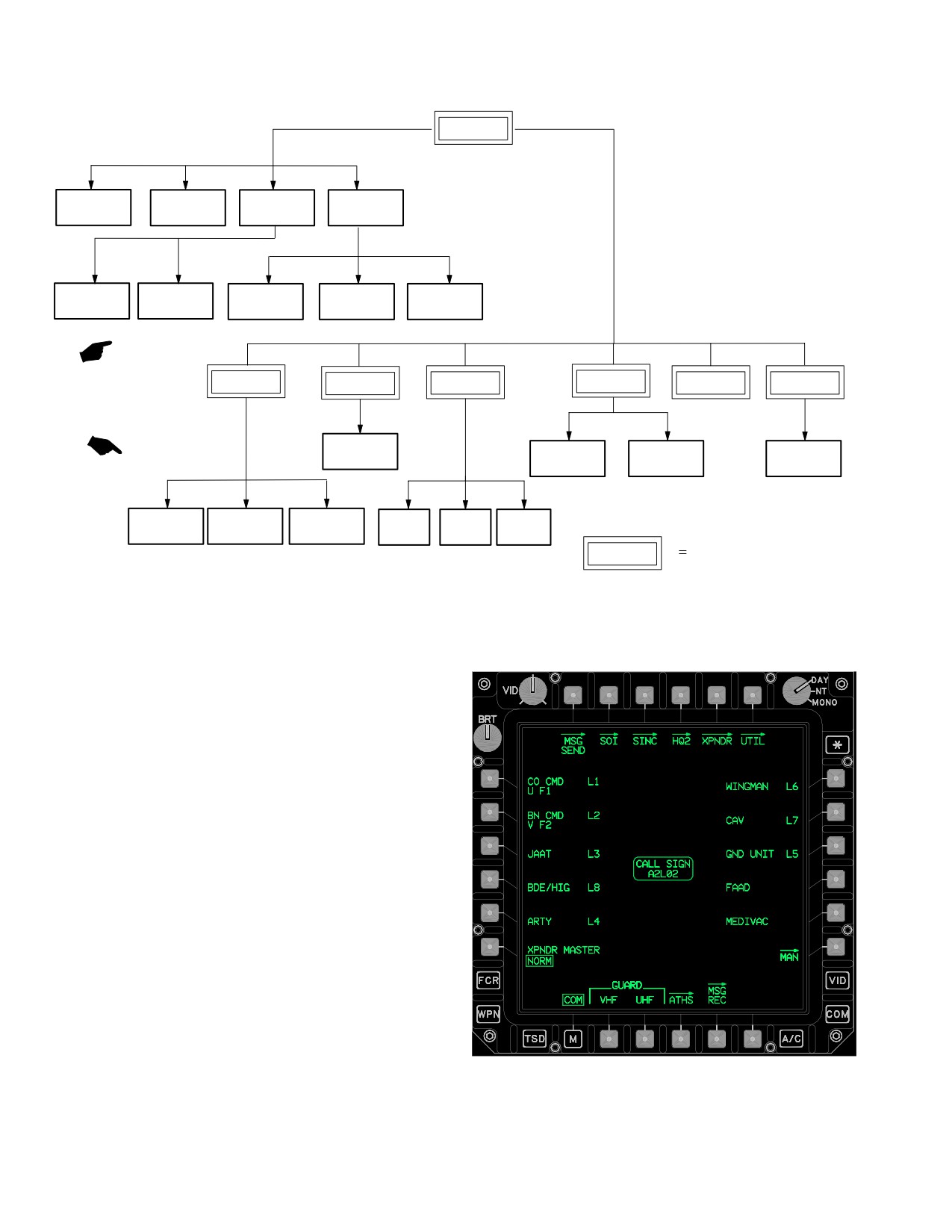
Figure 3-7. COM Subsystem Paging Tree
3.21 COMMUNICATIONS (COM) PAGE
The COM page (fig 3-8) is used to manage the ten net-
works. Of the ten available networks, only eight of them
can be digital. Selecting the COM subsystem button or the
COM page button from the MENU page displays the COM
page. Various communication subsystem status windows
and control selections are provided by bezel buttons lo-
cated along the edges of the format. The paging options at
the top of the page provide access to subsystem function-
al pages.
LBA5205
Figure 3-8. COM Page
Use or disclosure of this information is subject to the restriction(s) on the title page of this document.
3-14
Change 2
TM 1-1520-251-10
Buttons on the COM page are described below:
3.21.9 MAN Page Button. The MAN button displays
the MAN page.
• T1
MSG SEND button
• T2
SOI button
3.21.10 GUARD VHF Button. The GUARD VHF but-
• T3
SINC (SINCGARS) button
ton selects the GUARD VHF channel.
• T4
HQ1 or HQ2 button
3.21.11 GUARD UHF Button. The GUARD UHF but-
• T5
XPNDR button
ton selects the GUARD UHF channel.
• T6
UTIL (utility) button
• L1-L5
PRESET buttons
3.21.12 ATHS Button. The ATHS button displays the
• L6
XPNDR MASTER button
ATHS page.
• R1-R5
PRESET buttons
3.21.13 MSG REC Page Button. The MSG REC but-
• R6
MAN button
ton displays the message receive (MSG REC) page only
• B2
GUARD VHF button
when there are messages in the IDM.
• B3
GUARD UHF button
• B4
ATHS button
3.21.14 CALL SIGN Status Window. The CALL SIGN
status window indicates the ownship call sign.
• B5
MSG REC button
3.21.1 MSG SEND Page Button. The MSG SEND but-
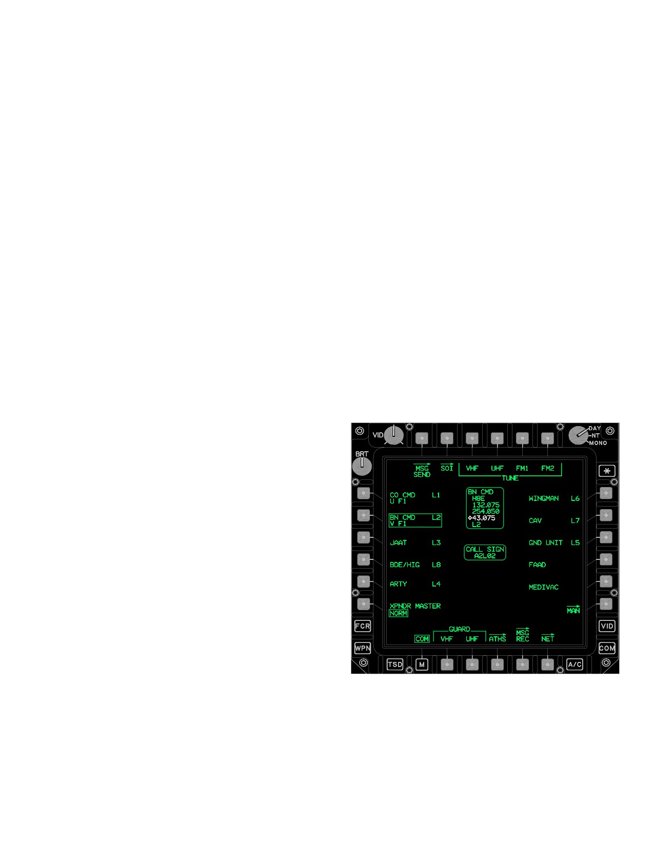
3.22 COM PAGE - PRESET SELECTED
ton displays the MSG SEND page.
The COM page preset status window is shown in Figure
3.21.2 SOI Page Button. The SOI button displays the
3-9.
SOI page.
3.21.3 SINC Page Button. The SINC button displays
the SINCGARS page.
3.21.4 HQ1 or HQ2 Page Button. The HQ1 or HQ2
button displays the appropriate page for the type of HAVE
QUICK installed.
3.21.5 XPNDR Page Button. The XPNDR button dis-
plays the XPNDR page.
3.21.6 UTIL Page Button. The UTIL button displays
the COM UTIL page.
3.21.7 PRESET Buttons. The PRESET (1-10) buttons
provide the capability to tune the VHF, UHF, FM 1, and FM
2 radios. They also provide configuration control for the
Improved Data Modem (IDM) channels. The text for each
preset button includes two lines of information. The first
line contains the unit ID, net type, and net number. The
second line contains the radio status.
LBA0403A
3.21.8 XPNDR MASTER Button. The XPNDR MAS-
TER button toggles between Standby (STBY) and Normal
(NORM) modes.
Figure
3-9.
COM Page (Preset Selected)
Use or disclosure of this information is subject to the restriction(s) on the title page of this document.
3-15
TM 1-1520-251-10
The following unique buttons are displayed on the COM
page when preset is selected:
• T3
TUNE VHF button
• T4
TUNE UHF button
• T5
TUNE FM1 button
• T6
TUNE FM2 button
• B6
NET page button
3.22.1 TUNE Button. The TUNE buttons are displayed
when the COM page is displayed and a preset button is
selected, or when the NET page is selected. Selecting a
TUNE button tunes that radio to the frequency displayed
and configures the channel of the IDM to the network dis-
played.
3.22.2 NET Page Button. The NET button displays the
net subscriber page. See paragraph 3.24.
3.22.3
COM PRESET Status Window. The COM
LBA0405A
PRESET status window displays the data associated with
the preset that is currently selected. Data is displayed in
the following order:
Figure
3-10.
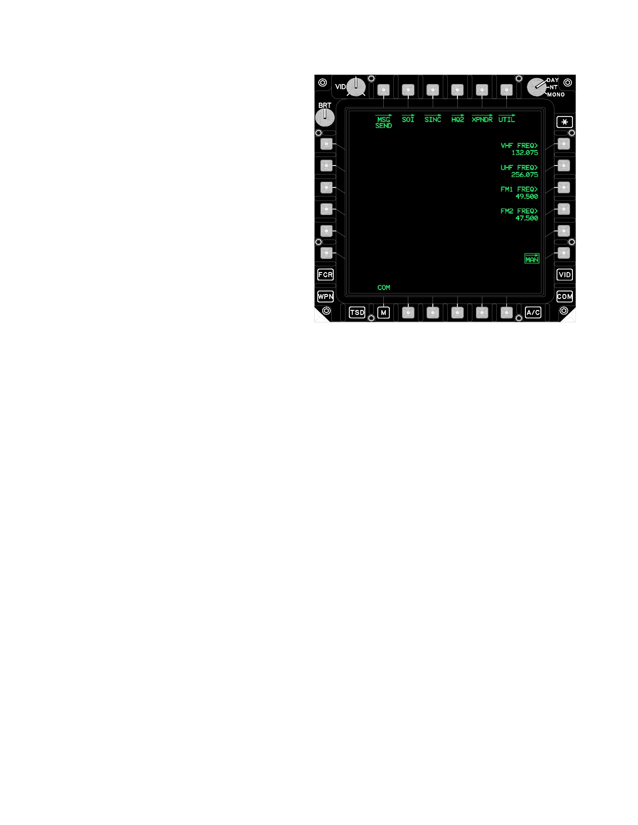
MAN Page
• 1) Unit ID
• 2) Call Sign
• 3) VHF Frequency
The MAN page contains the following unique buttons:
• 4) UHF Frequency
• R1
VHF FREQ button
• 5) FM Frequency
• R2
UHF FREQ button
• 6) IDM Type and IDM Net Number
•
R3
FM1 FREQ button
The Primary frequency is displayed in white and desig-
• R4
FM2 FREQ button
nated by a white arrow.
3.24 NET PAGE
3.23 MAN PAGE
The MAN page (fig 3-10) provides the capability to select
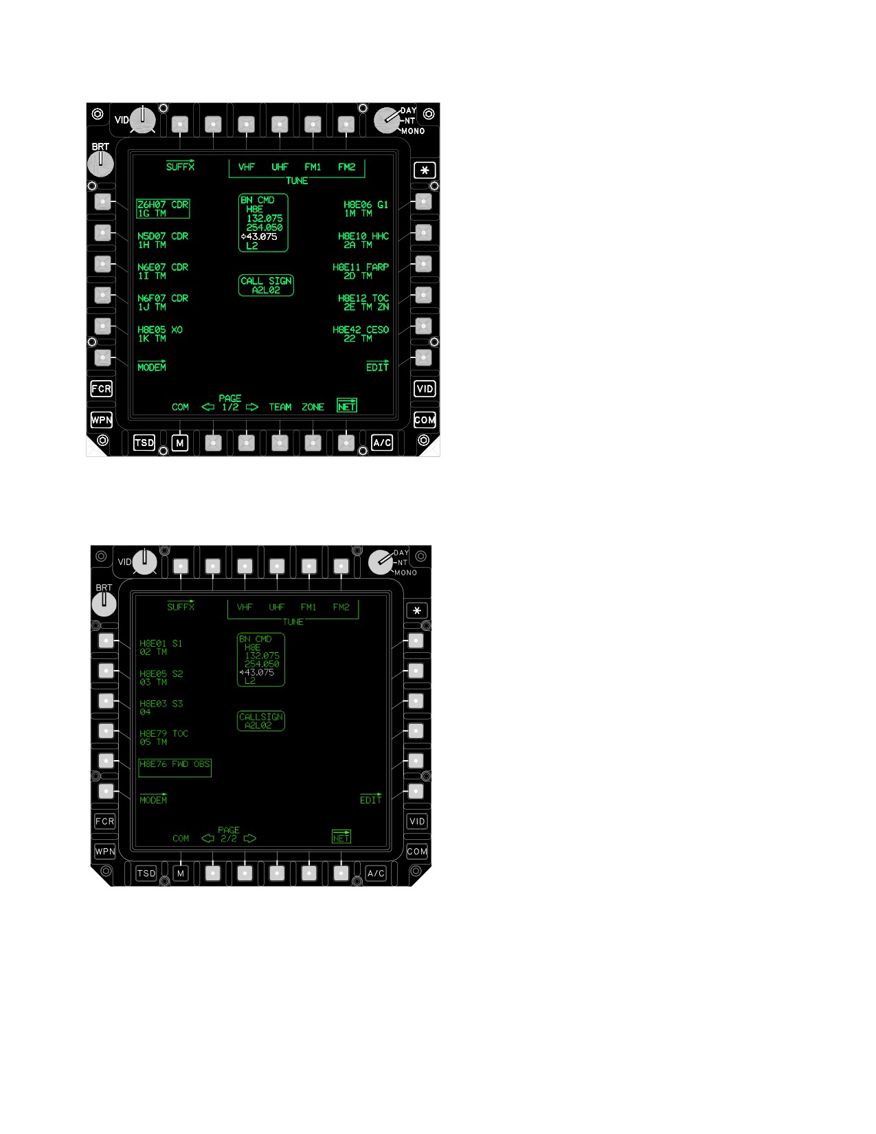
The NET page (figs 3-11 and 3-12) displays the preset
a radio button and tune to a non-preset frequency.
data associated with the selected preset.
Use or disclosure of this information is subject to the restriction(s) on the title page of this document.
3-16
TM 1-1520-251-10
• T2
CLEAR button
• T3
TUNE VHF button
• T4
TUNE UHF button
• T5
TUNE FM1 button
• T6
TUNE FM2 button
• L1-L5
Subscriber buttons
• L6
MODEM button
• R1-R5
Subscriber buttons
• R6
EDIT button
• B2
PAGE DOWN button
• B3
PAGE UP button
• B4
TEAM button
• B5
ZONE button
3.24.1 SUFFX Page Button. SUFFX button displays
the SUFFX page. This button is not displayed when the
net member currently selected has a subscriber ID. See
paragraph 3.25.
LBA5206
3.24.2 CLEAR Button. The CLEAR button, displayed in
white, only appears if the IDM is detected to have extraneous
Figure
3-11.
NET Page - (Team member selected)
subscribers. This may occur if the crew deletes subscribers
from a net, but then performs an upload of the original sub-
scriber data from the DTC. Pressing the CLEAR button will
delete the extraneous subscribers from the IDM.
3.24.3 Subscriber Buttons. The subscriber buttons
provide the capability to assign team and zone member
status for net subscribers.
3.24.4 MODEM Page Button. The MODEM button dis-
plays the MODEM page. See paragraph 3.27.
3.24.5 EDIT Page Button. The EDIT button displays
the EDIT page. See paragraph 3.26.
3.24.6 PAGE UP and PAGE DOWN Buttons. Allows
selection between two pages of subscribers.
3.24.7 TEAM Button. The TEAM button provides the
capability to toggle team designation on or off for net sub-
scribers. This button is only displayed if the net member
currently selected has a subscriber ID.
3.24.8 ZONE Button. The ZONE button provides the
capability to toggle zone designation on or off for net sub-
scribers. This button is only displayed if the net member
LBA2569
currently selected has a subscriber ID and if there are not
already seven subscribers designated as zone members.
Figure
3-12.
NET Page - (Net member selected, no
subscriber ID)
3.25 SUFFX PAGE
The SUFFX page (fig 3-13) is accessed by selecting the
SUFFX page button from the NET page. The SUFFX
The NET page contains the following unique buttons:
page provides only that data that has been loaded
• T1
SUFFX (Suffix) button
through the DTU.
Use or disclosure of this information is subject to the restriction(s) on the title page of this document.
3-17
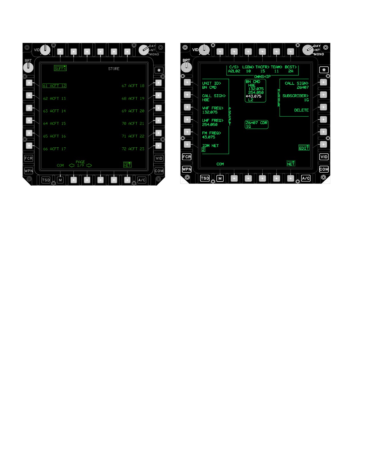
TM 1-1520-251-10
LBA5012
LBA5207
Figure 3-13. SUFFX Page
Figure 3-14. EDIT Page - (Preset with IDM net)
The SUFFX page contains the following unique buttons:
The EDIT page contains the following unique buttons:
• T5
STORE button
• T2
OWNSHIP C/S button
• L1-L6
Suffix buttons
• T3
OWNSHIP LBGW button
• R1-R6
Suffix buttons
• T4
OWNSHIP TACFR button
• B2
PAGE DOWN button
• T5
OWNSHIP TEAM button
• B3
PAGE UP button
•
T6
OWNSHIP BCST button
3.25.1 STORE Button. Selecting the STORE button
• L1
PRESET UNIT ID button
provides the capability to store the selected Suffix into a
selected subscriber button location on the NET page.
• L2
PRESET CALL SIGN button
• L3
PRESET VHF FREQ button
3.25.2
Suffix Buttons. The Suffix buttons are dis-
• L4
PRESET UHF FREQ button
played on the left and right sides of the SUFFX page.
• L5
PRESET FM FREQ button
3.25.3 PAGE UP and PAGE DOWN Buttons. Allows
• L6
PRESET IDM NET button
selection of multiple pages of suffixes.
•
R1
MEMBER CALL SIGN button
3.26 EDIT PAGE
• R2
MEMBER SUBSCRIBER button
• R3
MEMBER DELETE button
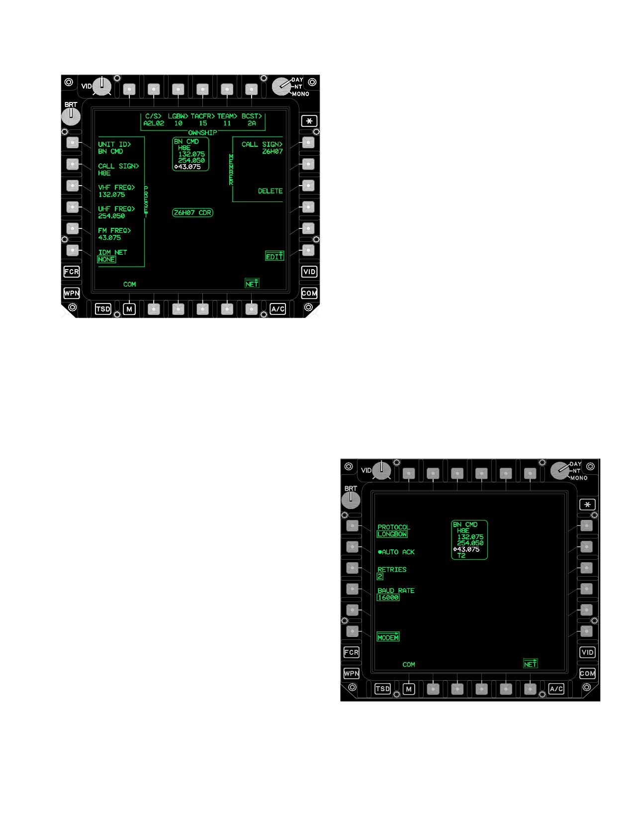
The EDIT page (figs 3-14 and 3-15) provides the capabili-
ty to modify preset and selected subscriber buttons.
• R6
EDIT button
Use or disclosure of this information is subject to the restriction(s) on the title page of this document.
3-18
TM 1-1520-251-10
3.26.7 PRESET VHF, UHF, FM FREQ Buttons. The
PRESET VHF, UHF, FM FREQ buttons provides the capa-
bility to change the selected preset frequency.
3.26.8 PRESET IDM NET Button. The PRESET IDM
NET button provides the capability to assign/unassign an
IDM net to a preset.
3.26.9 MEMBER CALL SIGN Button. The MEMBER
CALL SIGN button provides the capability to modify the
selected subscriber call sign. This button is only displayed
for a preset with an assigned IDM net.
3.26.10 MEMBER SUBSCRIBER Button. The MEM-
BER SUBSCRIBER button provides the capability to
modify the selected subscriber ID.
3.26.11 MEMBER DELETE Button. The MEMBER
DELETE button provides the capability to delete the se-
LBA2570A
lected subscriber. This button is only displayed for a pre-
set with an assigned IDM net and a valid call sign has
been entered in the MEMBER CALL SIGN button.
Figure 3-15. EDIT Page - (Preset without IDM net)
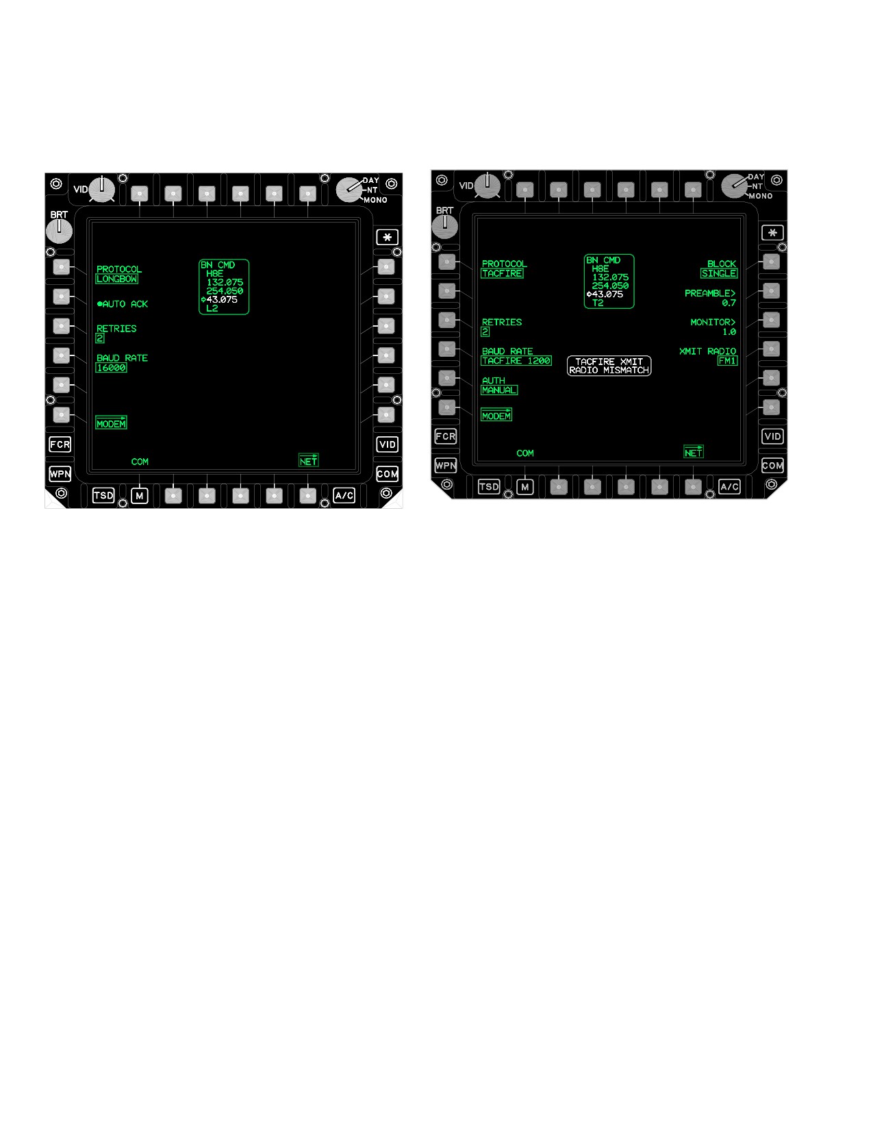
3.27 MODEM PAGE
3.26.1 C/S Button. The ownship call sign (C/S) button
provides the capability to modify the current call sign as
The MODEM page (fig 3-16) provides the capability to
displayed in the call sign status window.
modify the IDM net that is assigned to the PRESET but-
ton.
3.26.2 LGBW Button. The LGBW button provides the
capability to modify the originator ID for the Longbow Pro-
tocol. If an ID is not uploaded from the DTC, this button
will be displayed with a question mark to indicate that a
valid originator ID must be entered to transmit data.
3.26.3 TACFR Button. The TACFR button provides the
capability to modify the Originator ID for the TACFIRE pro-
tocol. This button functions exactly like the ORIG button
on the ATHS page.
3.26.4 TEAM Button. The TEAM button provides the
capability to modify the TEAM ID for the TACFIRE proto-
col. This button functions exactly like the TEAM button on
the ATHS page.
3.26.5 BCST Button. The BCST button provides the
capability to modify the Broadcast ID for the TACFIRE
protocol. This button functions exactly like the BC button
on the ATHS page.
LBA1883A
3.26.6
PRESET CALL SIGN Button. The PRESET
CALL SIGN button provides the capability to modify the
preselected preset call sign.
Figure
3-16.
MODEM Page
Use or disclosure of this information is subject to the restriction(s) on the title page of this document.
3-19
TM 1-1520-251-10
3.27.1 PROTOCOL Button. The PROTOCOL button
d. BAUD RATE Button. The BAUD RATE button
provides the capability to select either the LONGBOW or
provides baud rate options of 16000, 8000, 2400, 1200,
TACFIRE protocol.
600, 300, 150, or 75.
LBA5013
LBA5015
Figure 3-18. MODEM Page with TACFIRE Selected
Figure 3-17. PROTOCOL Page
3.27.3 TACFIRE PROTOCOL. If the multi - state PRO-
NOTE
TOCOL button is selected to TACFIRE, the following
unique buttons are displayed.
The Longbow Protocol used in the IDM is
also known as the Air Force Applications
• PROTOCOL button
Program Development (AFAPD)
•
RETRIES button
3.27.2
LONGBOW PROTOCOL. If the multi-state
• BAUD RATE button
PROTOCOL button is selected to LONGBOW, the follow-
• AUTH button
ing unique buttons are displayed.
•
BLOCK button
• PROTOCOL button
• PREAMBLE button
• AUTO ACK button
• MONITOR button
• RETRIES button
• XMIT RADIO button
• BAUD RATE button
a. PROTOCOL button. The PROTOCOL button
a. PROTOCOL Button. The PROTOCOL button
provides the capability to select TACFIRE protocol.
provides the capability to select LONGBOW protocol.
b. AUTO ACK Button. The AUTO ACK button pro-
b. RETRIES Button. The RETRIES button pro-
vides the capability to enable or disable the auto acknowl-
vides the capability to select the number of retransmis-
edge mode.
sions the IDM performs (2, 1, or 0) with no acknowledge-
ment from a subscriber.
c. RETRIES Button. The RETRIES button pro-
vides the capability to select the number of retransmis-
c. BAUD RATE Button. The BAUD RATE button
sions the IDM performs (2, 1, or 0) with no acknowledge-
provides baud rate options of 1200, 600, 300, 150, or 75.
ment from a subscriber.
TACFIRE 1200 and TACFIRE 600 are the only options
Use or disclosure of this information is subject to the restriction(s) on the title page of this document.
3-20
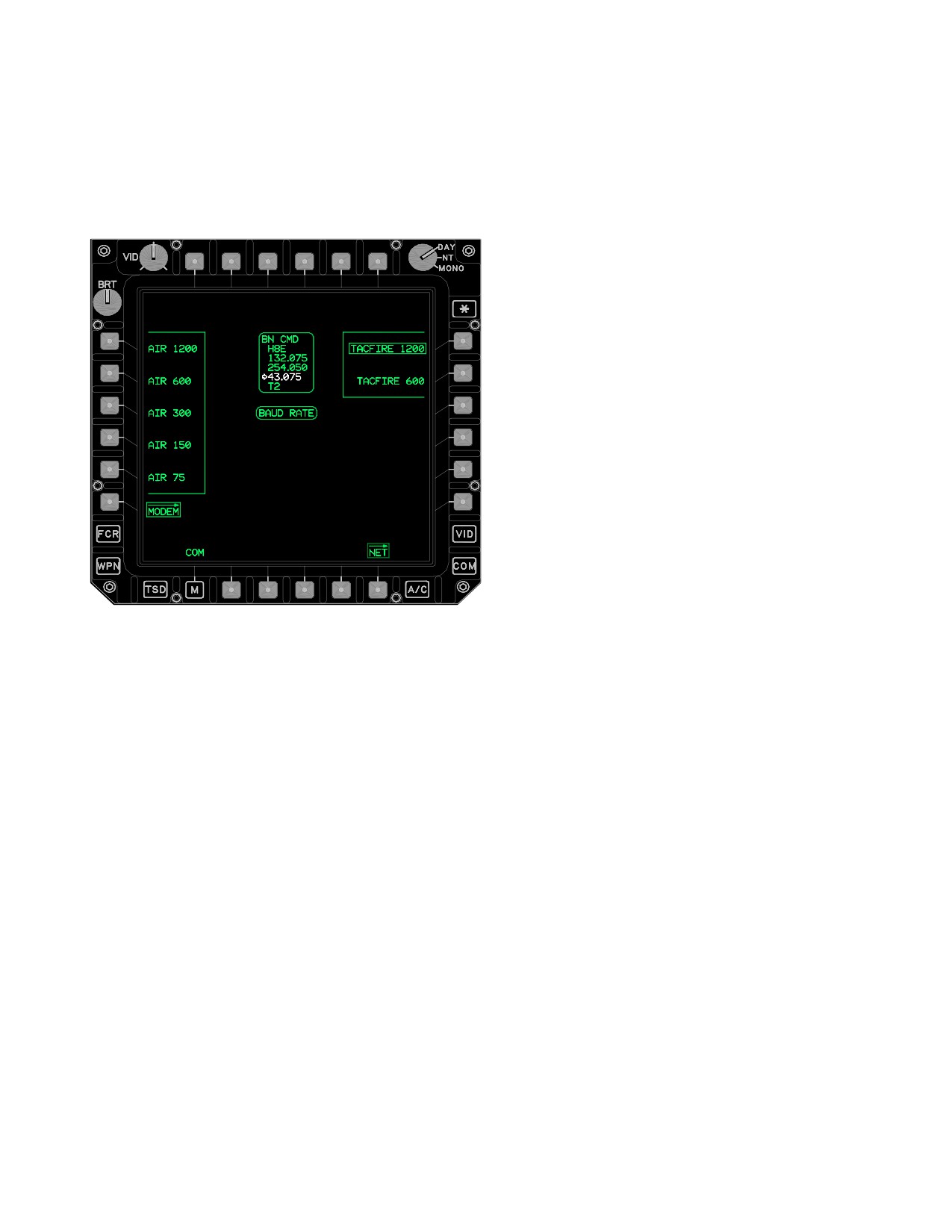
TM 1-1520-251-10
available for TACFIRE messages sent to artillery. TAC-
NOTE
FIRE 1200 is the default for the TACFIRE nets. The slow-
er rates for the AIR NETS are to be used only if reception
• A minimum preamble of 0.4 seconds is
is poor at high rates.
required when transmitting through cryp-
to equipment. The longer the preamble,
the longer the air time.
• When establishing communications with
AFATDS, ensure that 2.3 seconds is
used by both the AH - 64D and the artil-
lery.
f. PREAMBLE Button. The PREAMBLE button is
the ON AIR time that establishes a digital link between the
radios prior to the message being sent. Selecting the
PREAMBLE button provides the capability to modify this
ON AIR time. An interval between 0.1 and 9.9 seconds
may be entered.
g. MONITOR Button. Selection of the MONITOR
button allows the crew to modify the time that the IDM lis-
tens for interfering traffic prior to transmitting the mes-
sage. A time from 0.5 seconds to 9.9 seconds or OFF may
be entered. To turn this function off the crew must enter
zero, the word OFF is displayed on the ATHS page. If
more than 15 seconds have elapsed after the SEND but-
LBA5016
ton has been depressed, the IDM will reset automatically
and the SEND button must be pressed again. Voice trans-
mission has priority over digital transmission; therefore,
Figure
3-19.
MODEM Page with TACFIRE and
the IDM will wait until the airway is clear of voice traffic if a
BAUD RATE Selected
monitor time has been selected.
h. XMIT RADIO Button. Selection of the multi -
d. AUTH Button. The AUTH two - state button al-
state XMIT RADIO button allows the crew to select the ra-
lows the crew to toggle between NONE and MANUAL. If
dio that the IDM will use to transmit the TACFIRE digital
NONE is selected, no authentication is required. This
messages. Preset options of VHF, UHF, FM1 and FM2 are
function automatically displays NONE due to use of auto-
displayed upon selection of of the XMIT RADIO button.
matic authentication. If MANUAL is selected, an operator
When the preset is selected and tuned to a radio, that ra-
input of the transmission authenticator is required each
dio will be set at XMIT RADIO. After the preset has been
time transmission is attempted. MANUAL authentication
tuned to a radio, this button allows the operator to config-
is normally only used in air - to - air or air - to - ground TAC-
ure it to a different radio. Artillery TACFIRE nets are nor-
FIRE. If MANUAL is selected, but no manual authentica-
mally set on FM1 or FM2.
tion is desired at the time of transmission, the message
will be sent on the second press of the SEND button.
3.28 MSG REC PAGE
e. BLOCK Button. The BLOCK two - state button
allows the crew to toggle between SINGLE and DOUBLE.
The MSG REC page (fig 3-20) provides the capability to
SINGLE BLOCK sends each segment of data once per
manage IDM messages that are received within the IDM
SEND. DOUBLE BLOCK sends each data segment twice
buffer. The crew is cued when a message is received by
per SEND. DOUBLE should be used when atmospheric
UFD advisory and the message appearing on the MPD.
conditions/reception are poor or when jamming is sus-
The MSG REC page button is not displayed when there
pected.
are no messages within the IDM buffer.
Use or disclosure of this information is subject to the restriction(s) on the title page of this document.
3-21
TM 1-1520-251-10
• B2
PAGE DOWN button
• B3
PAGE UP button
NOTE
Storage of an IDM message will overwrite
the selected mission data.
3.28.1 STORE/RVW Button. The STORE/RVW button
provides the capability to store a data message or review
a LONGBOW free text or any TACFIRE message re-
ceived within or via the IDM. These buttons are only dis-
played after a message button has been selected. If a
TACFIRE message is selected for review, then upon ac-
tivation of the RVW button the page will automatically
switch to the page MSG RCVD page of the ATHS TAC-
FIRE. Refer to fig. 3-60 in the ATHS section para 3.53 for
more information.
3.28.2 DEL Button. Selecting this button deletes the
IDM message associated with the selected Message but-
LBA1887
ton.
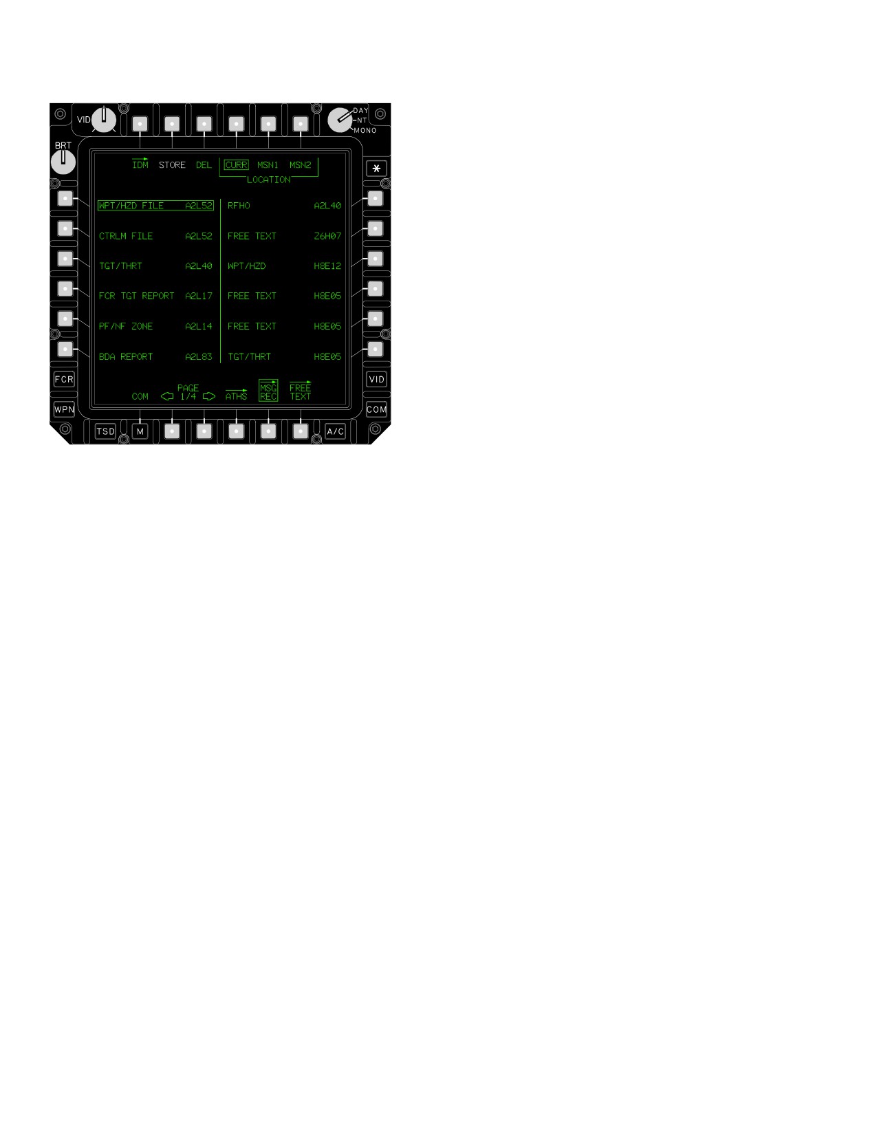
Figure 3-20. Message Receive Page
3.28.3 LOCATION CURR/MSN1/MSN2 Buttons. The
MSG REC Page CURR, MSN1, and MSN2 buttons (fig
3-20) allow crewmembers to control where the current
The MSG REC page contains the following unique but-
message will be stored when the STORE button is se-
tons:
lected.
• T2
STORE button or RVW button
3.28.4 Message Buttons. There can be up to 12 mes-
• T3
DEL button
sages buttons per page (fig 3-21), up to 4 pages. The type
of message will be displayed, along with the call sign of
• T4
LOCATION CURR button
the subscriber who transmitted the message. New incom-
• T5
LOCATION MSN1 button
ing messages are displayed on the bottom of the page.
The example shows FREE TEXT selected.
• T6
LOCATION MSN2 button
• L1-L6
Message Receive buttons
3.28.5 PAGE UP and PAGE DOWN Buttons. Allows
• R1-R6
Message Receive buttons
selection of multiple pages of received IDM messages.
Use or disclosure of this information is subject to the restriction(s) on the title page of this document.
3-22
TM 1-1520-251-10
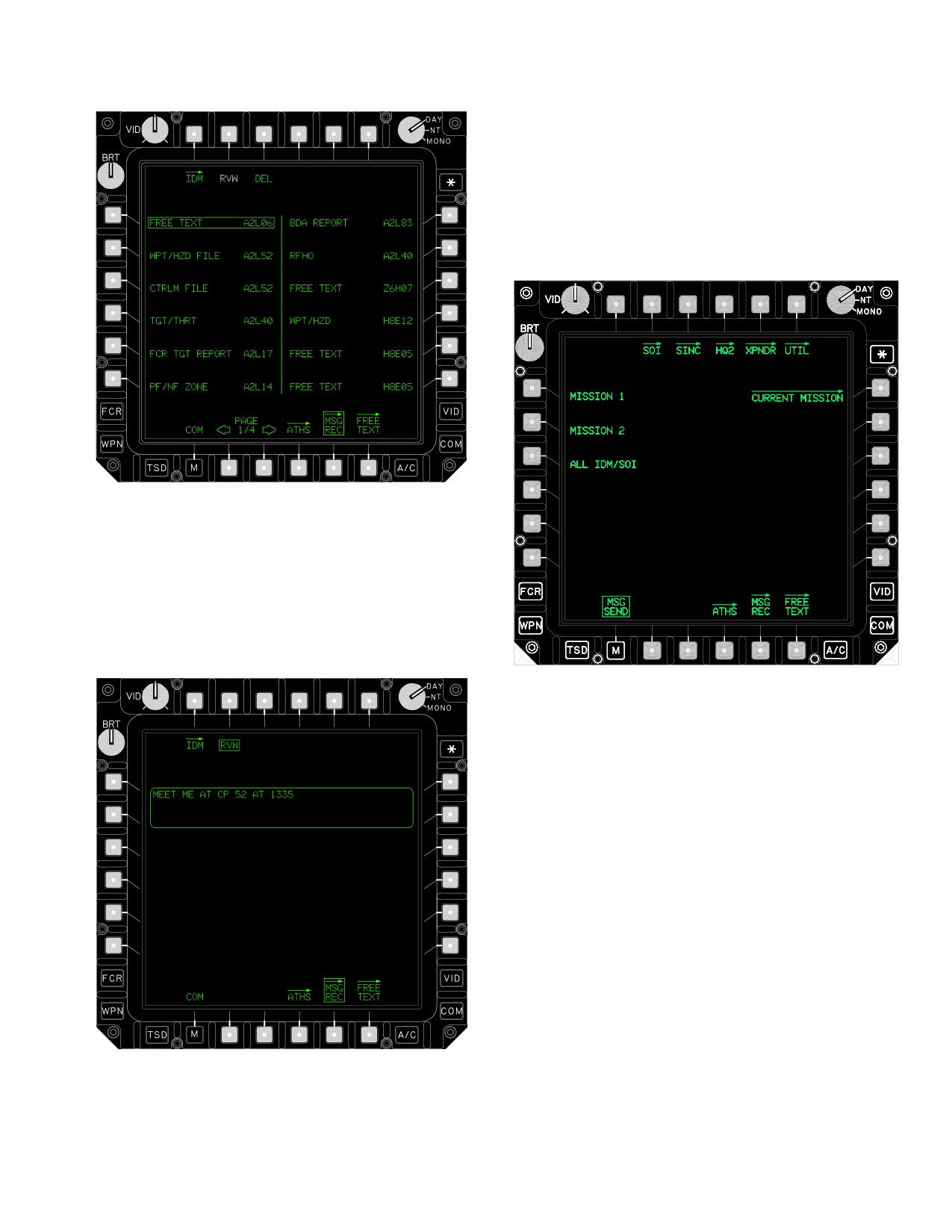
3.29 IMPROVED DATA MODEM (IDM) PAGE
The IDM page (fig 3-23) provides controls to send MIS-
SION 1, MISSION 2, or ALL IDM/SOI data files via the
IDM to team members. It also provides access to the
CURRENT MISSION page which is used for sending se-
lected components of the current mission to team mem-
bers.
LBA1884
Figure 3-21. Message Buttons (FREE TEXT
selected)
3.28.6
FREE TEXT Message Window. The FREE
TEXT Message Window (fig 3-22) allows the crewmem-
bers to review Free Text messages received over the IDM.
LBA5207
Figure 3-23. IDM Page
The IDM page contains the following unique buttons:
• L1
MISSION 1 button
• L2
MISSION 2 button
• L3
ALL IDM/SOI buttons
• R1
CURRENT MISSION button
• R6
SEND button
3.29.1 MISSION 1 (or 2) Buttons. The IDM MISSION
buttons provides the capability to transmit the MISSION 1
(or 2) files upon the selection of the IDM SEND button.
3.29.2 ALL IDM/SOI Button. The ALL IDM/SOI button
provides the capability to transmit the SOI and IDM net
files when the SEND button is selected.
LBA1886
3.29.3 CURRENT MISSION Button. The CURRENT
MISSION button displays the CURRENT MISSION page.
Figure
3-22. FREE TEXT Message Window
See paragraph 3.30.
Use or disclosure of this information is subject to the restriction(s) on the title page of this document.
3-23
TM 1-1520-251-10
3.29.4 SEND Button. The SEND button is only dis-
• L4
ROUTE (CURRENT) button
played if the MISSION 1 (or 2) button or ALL IDM/CEOI
• L5
TGT/THRT button
button has been selected. The selection of the SEND but-
• L6
CONTROL MEASURES button
ton will command the system to transmit the selected files
through the selected channel of the IDM. The data is only
• R2
LASER CODES button
sent to team members.
• R6
SEND button
• B4
ALL button
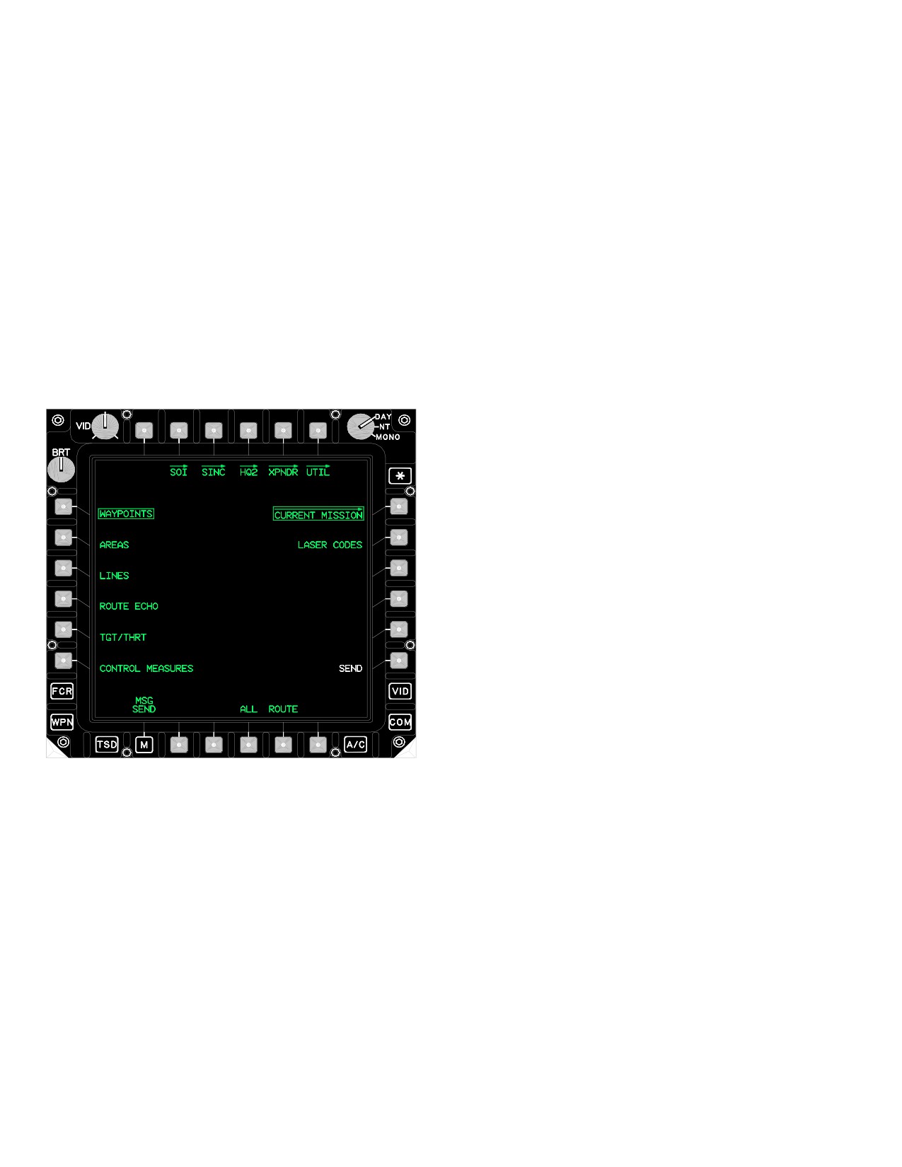
3.30 CURRENT MISSION PAGE
• B5
ROUTE button
The CURRENT MISSION button displays the CURRENT
3.30.1 WAYPOINTS Button. The WAYPOINTS button
MISSION page (fig 3-24). The CURRENT MISSION page
allows sending of the current waypoints file over the IDM.
provides the capability to individually select the type of in-
formation to be sent over the IDM. Selection of the ALL
3.30.2
AREAS Button. The AREAS button allows
button allows transmission of all current files. Once an
sending of the current engagement areas file over the
item is selected, selecting the SEND button will initiate
IDM.
transmission over the IDM.
3.30.3 LINES Button. The LINES button allows send-
ing of the current phase lines file over the IDM.
3.30.4
ROUTE Button. The ROUTE button allows
sending of the current route file over the IDM.
3.30.5 TGT/THRT Button. The TGT/THRT button al-
lows sending of the current target and threats file over the
IDM.
3.30.6
CONTROL MEASURES Button. The CON-
TROL MEASURES button allows sending of the current
control measures file over the IDM.
3.30.7 LASER CODES Button. The LASER CODES
button allows sending the current laser codes file over the
IDM.
3.30.8 SEND Button. The SEND button is only dis-
played if a valid CURRENT MISSION file is selected to be
LBA1990A
sent. The selection of the SEND button will command the
system to transmit the selected files through the selected
Figure 3-24. CURRENT MISSION Page
channel of the IDM. The data is only sent to team mem-
bers.
The CURRENT MISSION page contains the following
3.30.9 ALL Button. The ALL button allows sending of
unique buttons:
all current mission files over the IDM.
• L1
WAYPOINTS button
3.30.10 ROUTE Button. The ROUTE button presents
• L2
AREAS button
all of the current routes files available for sending over the
• L3
LINES button
IDM (fig 3-25).
Use or disclosure of this information is subject to the restriction(s) on the title page of this document.
3-24
TM 1-1520-251-10
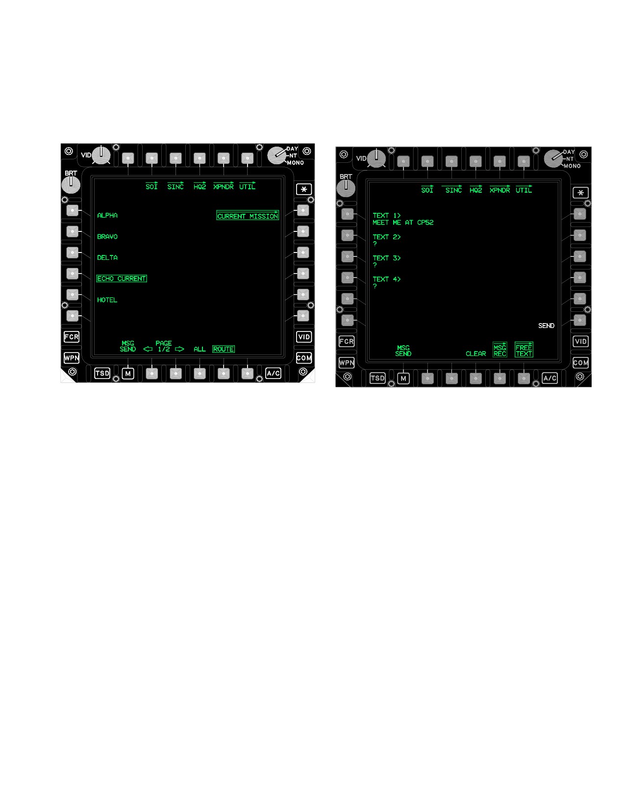
3.31 CURRENT MISSION - ROUTE SELECTIONS
3.32 FREE TEXT PAGE
The ROUTE button (fig 3-25) provides the capability to se-
The FREE TEXT page (fig 3-26) provides the operator the
lect various routes.
capability to create a free text message for transmission
through the IDM.
LBA1991A
LBA1992A
Figure 3-26. FREE TEXT Page
Figure 3-25. ROUTE button selected
The FREE TEXT page contains the following unique but-
The ROUTE button provides the following selections:
tons:
• L1-L5
ROUTE buttons
• L1-L4
TEXT (1-4) buttons
• B2
PAGE DOWN button
• R6
SEND button
• B3
PAGE UP button
• B4
CLEAR button
• B4
ALL button
3.32.1 TEXT Buttons. Each TEXT (1-4) button pro-
vides the capability to load four 44-character messages
3.31.1 ROUTE Buttons. The ROUTE buttons allows
into the system for transmission by the ID.
selection of a single route file to send over the IDM.
3.32.2 SEND Button. The SEND button transmits the
3.31.2 PAGE UP and PAGE DOWN Buttons. Allows
FREE TEXT message through the selected channel of the
selection between two lists of routes.
IDM. The data is only sent to team members.
3.31.3 ALL Button. The ALL button allows sending of
3.32.3 CLEAR Button. The CLEAR button clears the
all route files over the IDM.
data contained on the FREE TEXT page.
Use or disclosure of this information is subject to the restriction(s) on the title page of this document.
3-25
TM 1-1520-251-10
3.33 SIGNAL OPERATING INSTRUCTIONS (SOI)
Page
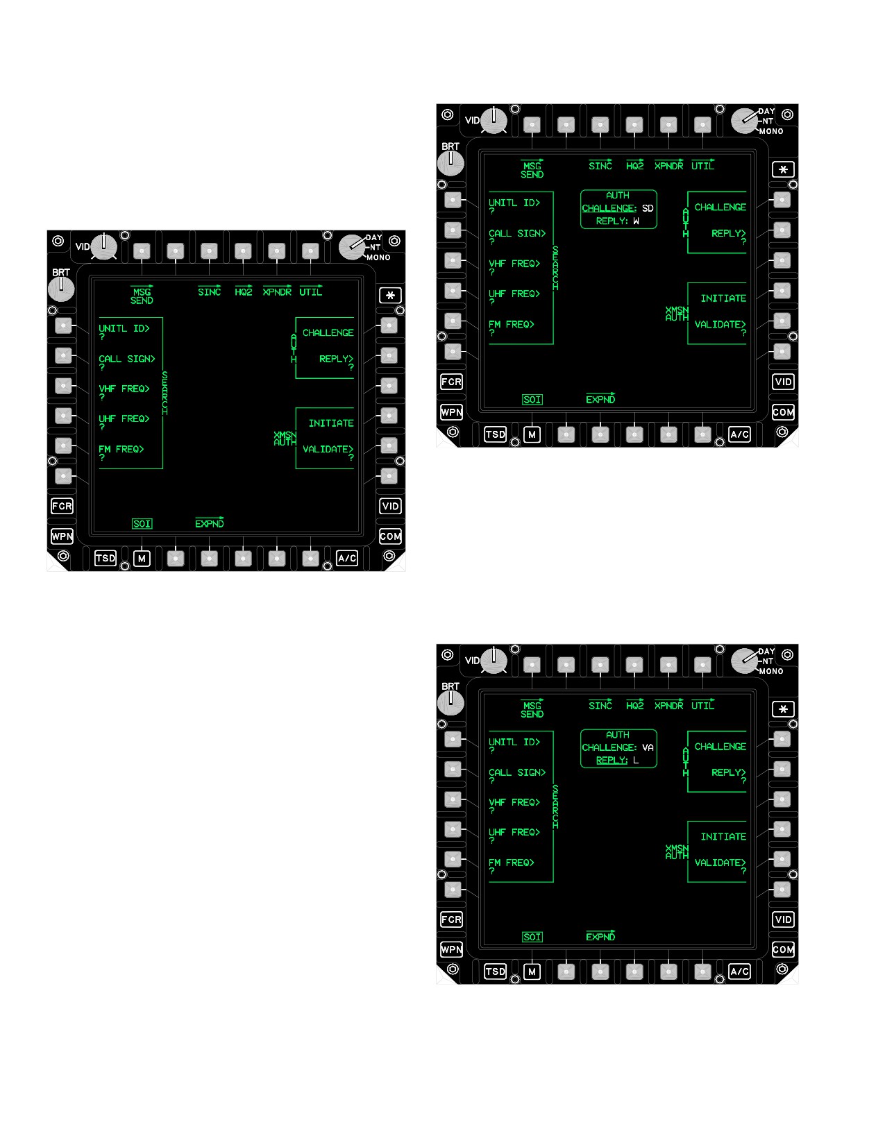
The SOI page (fig 3-27) provides the capability to authen-
ticate communications transmissions.
LBA2021A
Figure 3-28. SOI Page - AUTH CHALLENGE
3.33.2 AUTH REPLY Button. The AUTH REPLY but-
ton (fig 3-29) provides the capability to enter a challenge
code and extract the reply code from the challenge/reply
LBA0409A
table and display the code within the AUTH CHALLENGE
REPLY window.
Figure 3-27. SOI Page
The SOI page contains the following unique buttons:
• L1
SEARCH UNIT ID button
• L2
SEARCH CALL SIGN button
• L3
SEARCH VHF FREQ button
• L4
SEARCH UHF FREQ button
• L5
SEARCH FM FREQ button
• R1
AUTH CHALLENGE button
• R2
AUTH REPLY button
• R4
XMSN AUTH INITIATE button
• R5
XMSN AUTH VALIDATE button
• B3
EXPND (Expander) page button
3.33.1
AUTH CHALLENGE Button. The AUTH
LBA2022A
CHALLENGE button (fig 3-28) provides the capability to
extract the challenge/reply table and display the codes
within the AUTH CHALLENGE REP window.
Figure 3-29. SOI Page - AUTH REPLY
Use or disclosure of this information is subject to the restriction(s) on the title page of this document.
3-26
TM 1-1520-251-10
3.33.3
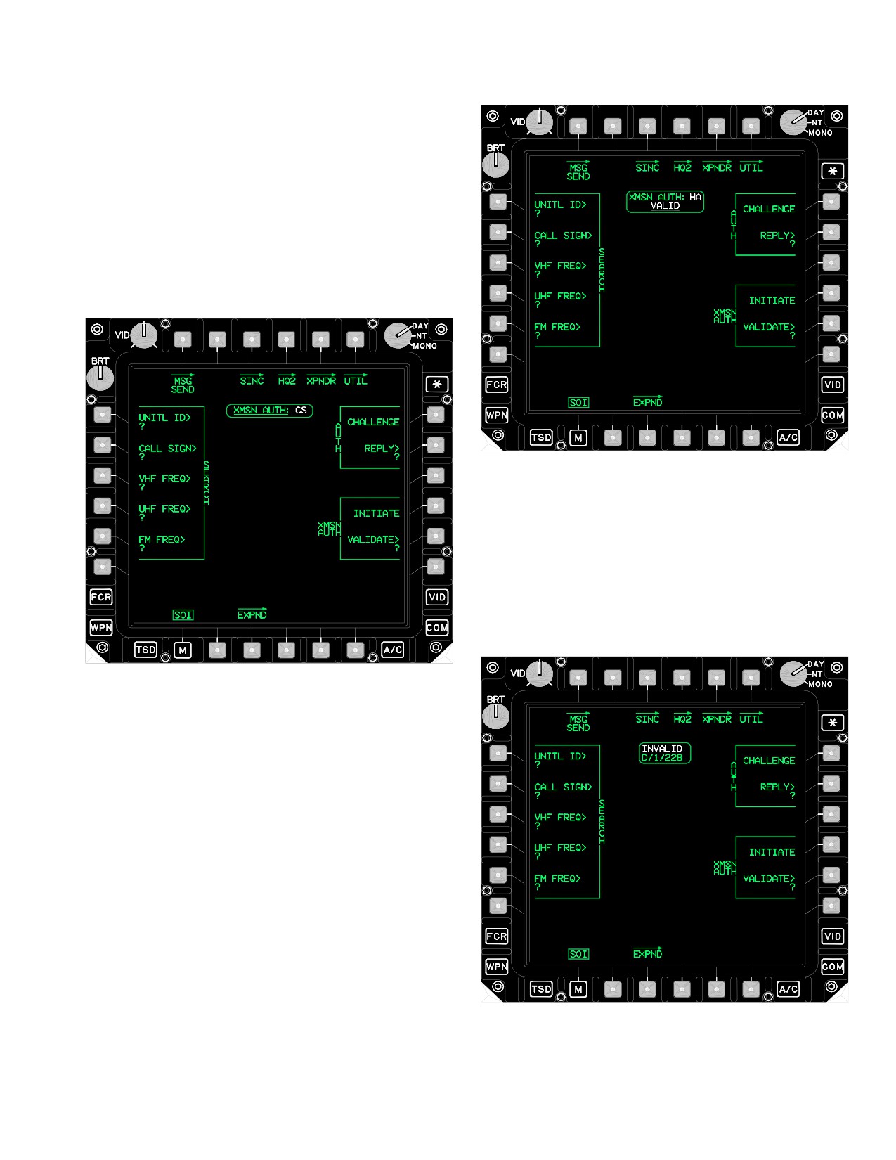
XMSN AUTH INITIATE Button. The XMSN
AUTH INITIATE button (fig 3-30) extracts the transmit au-
thentication codes from the transmit authentication table
and display the codes within the XMSN AUTH window.
The ALL CODES USED message will be displayed in
white.
LBA2024A
Figure 3-31. SOI Page - XMSN AUTH VALIDATE
3.33.5
SEARCH Mode. The SEARCH buttons (fig
3-32) provides the capability to enter a unit ID, frequen-
cies or call sign. The system will then search the SOI data-
base, extract and display the associated unit ID, frequen-
cies and call sign. The data displayed can then be loaded
into one of the ten preset locations.
LBA2023A
Figure 3-30. SOI Page - XMSN AUTH INITIATE
3.33.4 XMSN AUTH VALIDATE Button. The XMSN
AUTH VALIDATE button (fig 3-31) provides the capability
to verify a transmit authentication code from the transmit
authentication table. The VALID label is displayed when
the transmit authentication matches the transmit authenti-
cation code entered through the KU. The INVALID label is
displayed when the transmit authentication table does not
LBA2606A
match the transmit authentication code entered through
the KU.
Figure 3-32. SOI Page - SEARCH INVALID
Use or disclosure of this information is subject to the restriction(s) on the title page of this document.
3-27
TM 1-1520-251-10
a. Invalid Window. An Invalid Window is dis-
preset. Which causes return to the main CEOI page for-
played on the SOI page if no corresponding unit ID, fre-
mat.
quency, or call sign is found.
3.33.7 Expander (EXPND) Page Button. The EXPND
button displays the EXPND page. See paragraph 3.34.
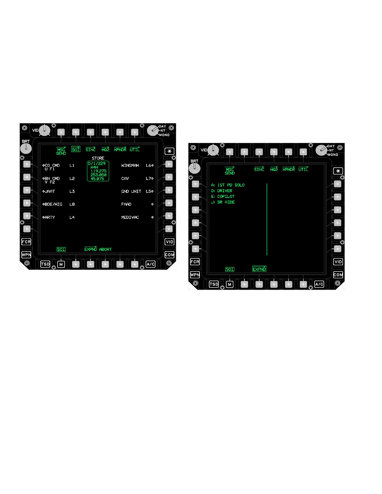
3.33.6 STORE Status Window. Upon completion of a
successful search of the SOI database, the SOI page is
3.34 EXPANDER (EXPND) PAGE
displayed containing a status window with a STORE label
on top (fig 3-33). The STORE status window contains the
The EXPND page (fig 3-34), a view - only page, provides
unit ID, call sign, and frequencies.
the capability to view the expander lookup table. The ex-
pander lookup table displays the one character expander
and descriptor field. Up to 26 expanders may be displayed
from the lookup table.
LBA1993A
Figure 3-33. SOI Page - SEARCH/STORE
LBA0689A
Figure 3-34. EXPND Page
a. Search/Store Buttons. The Search/Store pre-
set buttons provides the capability to store data that is
contained within the STORE status window into one of the
3.35 SINCGARS (SINC) PAGE
10 preset locations, as shown in white and designated by
The SINC page (figs 3-35 through 3-39) provides the ca-
an arrow.
pability to control the FM radios and their FH modes. The
b. Search ABORT Button. The Search ABORT
radio control buttons on the SINC page are only displayed
button provides the capability to abort the storing of a new
if the radio is installed.
Use or disclosure of this information is subject to the restriction(s) on the title page of this document.
3-28
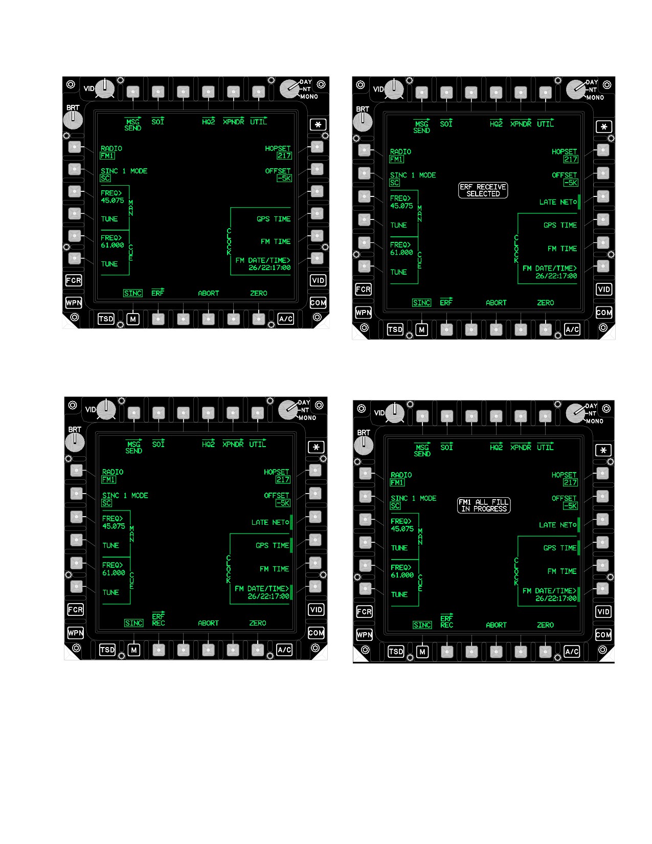
TM 1-1520-251-10
LBA0410A
LBA5209
Figure 3-35. SINC Page - SC M
Figure 3-37. SINC Page - FH/M MODE
LBA5208
LBA5210
Figure 3-36. SINC Page - FH MODE
Figure 3-38. SINC Page - FILL IN PROGRESS
Use or disclosure of this information is subject to the restriction(s) on the title page of this document.
3-29
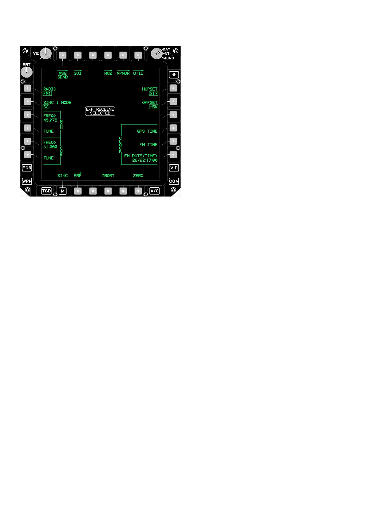
TM 1-1520-251-10
to the ERF Receive Page. FH/M mode allows access to
the ERF Send Page.
3.35.3
MAN FREQUENCY Button. The MAN FRE-
QUENCY button provides the capability to change the
Manual frequency of the selected radio.
3.35.4
MAN TUNE Button. The MAN TUNE button
provides the capability to tune the radio to the frequency
that is displayed within the MAN FREQUENCY button.
3.35.5
CUE FREQUENCY Button. The CUE FRE-
QUENCY button provides the capability to change the
Cue frequency of the selected radio.
3.35.6 CUE TUNE Button. The CUE TUNE button pro-
vides the capability to tune the radio to the frequency that
is displayed within the CUE FREQUENCY button.
3.35.7 HOPSET Button. The HOPSET button provides
LBA5015
seven options that include the six HOPSET buttons and
the MAN button. The hopset ID selected determines the
radio FH characteristics (hopping rate, frequencies, and
Figure 3-39. SINC Page - ERF RECEIVE SELECTED
frequency order).
The SINC page contains the following unique buttons:
3.35.8 OFFSET Button. The OFFSET button provides
the capability to control the offset (-10K,
-5K, 0, +5K,
• L1
RADIO button
+10K) from the single channel FM frequency.
• L2
SINC 1 MODE or SINC 2 MODE buttons
3.35.9 LATE NET Button. The LATE NET button is
• L3
MAN FREQUENCY button
used to synchronize to an operational net whose TOD is
• L4
MAN TUNE button
not within the 4 second (plus/minus) frequency hopping
communication window. The late net function may only be
• L5
CUE FREQUENCY button
used if the two net TODs are within 1 minute (plus/minus)
• L6
CUE TUNE button
of each other. This button is only displayed when the SINC
• R1
HOPSET button
mode is FH.
• R2
OFFSET button
3.35.10 CLOCK GPS TIME Button. The GPS TIME
• R3
LATE NET button
button causes the current time from the EGI to be loaded
• R4
CLOCK GPS TIME button
into the radio and extracts that time from the selected ra-
dio and displays the data within the DATE/TIME button.
• R5
CLOCK FM TIME button
• R6
CLOCK FM DATE/TIME button
3.35.11 CLOCK FM TIME Button. The FM TIME but-
• B6
ZERO button
ton extracts the current time from the selected radio and
displays the data within the DATE/TIME button.
3.35.1 RADIO Button. The RADIO button provides the
capability to toggle the display between the FM1 and the
3.35.12
CLOCK FM DATE/TIME Button. The FM
FM2 radio controls.
DATE/TIME button provides the capability to change the
date and time currently loaded into the selected radio.
3.35.2 SINC MODE Button. The SINC MODE button
This data is displayed for 1 minute, then is considered
provides the capability to control the mode of the selected
stale.
radio. The button provides options of SINC SC, SINC FH,
and SINC FH/M (Frequency Hopping/Master). SC mode
3.35.13 ZERO Button. The ZERO button provides the
allows access to the ERF Page. FH mode allows access
capability to zeroize the FM radio.
Use or disclosure of this information is subject to the restriction(s) on the title page of this document.
3-30
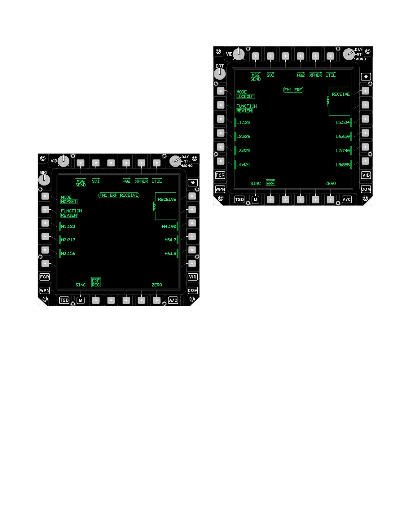
TM 1-1520-251-10
3.35.14 ERF RECEIVE WINDOW. The white ERF RE-
CEIVE WINDOW will display on the SINC, ERF, and ERF
SEND pages whenever the ERF RECEIVE button (R1) on
the ERF RECEIVE page is left selected for receipt of mul-
tiple ERFs.
3.36 ERF RECEIVE PAGE
The ERF RECEIVE page (figs 3-40 and 3-41) provides
the capability to initiate receive of hopsets and lockouts.
LBA5211
Figure 3-41. ERF RECEIVE Page - Lockout Mode
3.36.1 ERF MODE Button. The ERF MODE button op-
erates in two modes: HOPSET and LOCKOUT. The HOP-
SET mode configures the system for the reception of hop-
sets. The LOCKOUT mode configures for the reception of
lockout sets.
3.36.2 ERF FUNCTION. The ERF FUNCTION button
LBA1995A
provides the capability to select REVIEW and DELETE for
hopsets and lockouts and COPY functions for hopsets.
3.36.3 ERF HOPSET Buttons. Selecting one of the
Figure 3-40. ERF RECEIVE Page - Hopset Mode
ERF HOPSET buttons (figs 3-40) stores the hopset that is
displayed within the RECEIVE hopset window to that but-
ton.
The ERF RECEIVE page contains the following unique
buttons:
3.36.4 ERF LOCKOUT Buttons. The ERF LOCKOUT
buttons are only selectable when deleting LOCKOUTS.
• L1
ERF MODE button
• L2
ERF FUNCTION button
3.36.5 ERF RECEIVE Button. The ERF RECEIVE but-
ton provides the capability to command the radio to the
• L3-L6
ERF HOPSET/LOCKOUT buttons
ERF receive mode. The radio remains in the ERF receive
mode to receive multiple ERFs for 5 minutes unless the
• R1
ERF RECEIVE button
ERF RECEIVE button is manually deselected or automat-
• R2
ERF CLEAR button
ically deselected when a confirmed CLEAR (R2) is per-
formed. When a hopset or lockout set is received, this but-
• R3-R6
ERF HOPSET/LOCKOUT buttons
ton will be barriered until the HOPSET or LOCKOUT is
• B3
ERF STORE button
either cleared or stored (fig 3-42).
Use or disclosure of this information is subject to the restriction(s) on the title page of this document.
3-31
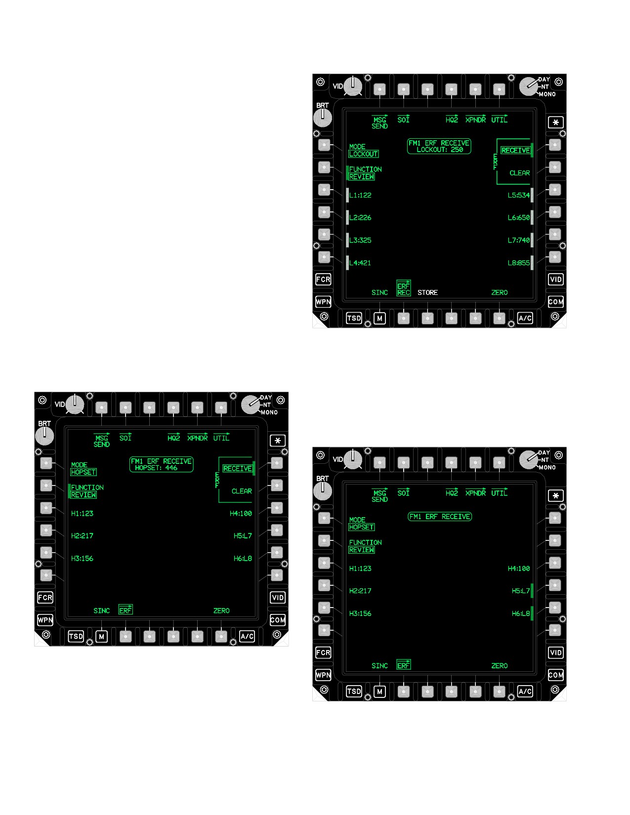
TM 1-1520-251-10
3.36.6 ERF CLEAR Button. The ERF CLEAR button
provides the capability to clear a HOPSET or LOCKOUT
from the holding memory buffer. The CLEAR button will
display upon receipt of a HOPSET or LOCKOUT and
when in COPY or EDIT modes.
NOTE
A YES/NO confirmation will only display
when the CLEAR button is used to clear a
received HOPSET or LOCKOUT.
3.36.7 ERF RECEIVE Button. The ERF RECEIVE but-
ton provides the capability to command the radio to the
ERF receive mode. The radio remains in the ERF receive
mode for 5 minutes or until the deselection of the ERF RE-
CEIVE button.
3.36.8 ERF STORE Button. The STORE button provides
the capability to load the lockout set into one of the eight lock-
out set locations within the current lockout window.
3.36.9 RECEIVED HOPSET Window. The RECEIVED
LBA5213
HOPSET window (fig 3-42) is displayed when the system
has received a valid HOPSET. The HOPSET will be dis-
Figure 3-43. ERF RECEIVE Page - Lockout
played in white.
Received
3.37 ERF SEND PAGE
The ERF SEND page (figs 3-44 and 3-45) provides the
capability to send hopsets and lockouts.
LBA5212
Figure 3-42. ERF RECEIVE Page - Hopset Received
LBA5214
3.36.10
RECEIVED LOCKOUT Window. The RE-
CEIVED LOCKOUT window (fig 3-43) is displayed when
the system has received a valid LOCKOUT.
Figure 3-44. ERF SEND Page - Hopset Mode
Use or disclosure of this information is subject to the restriction(s) on the title page of this document.
3-32
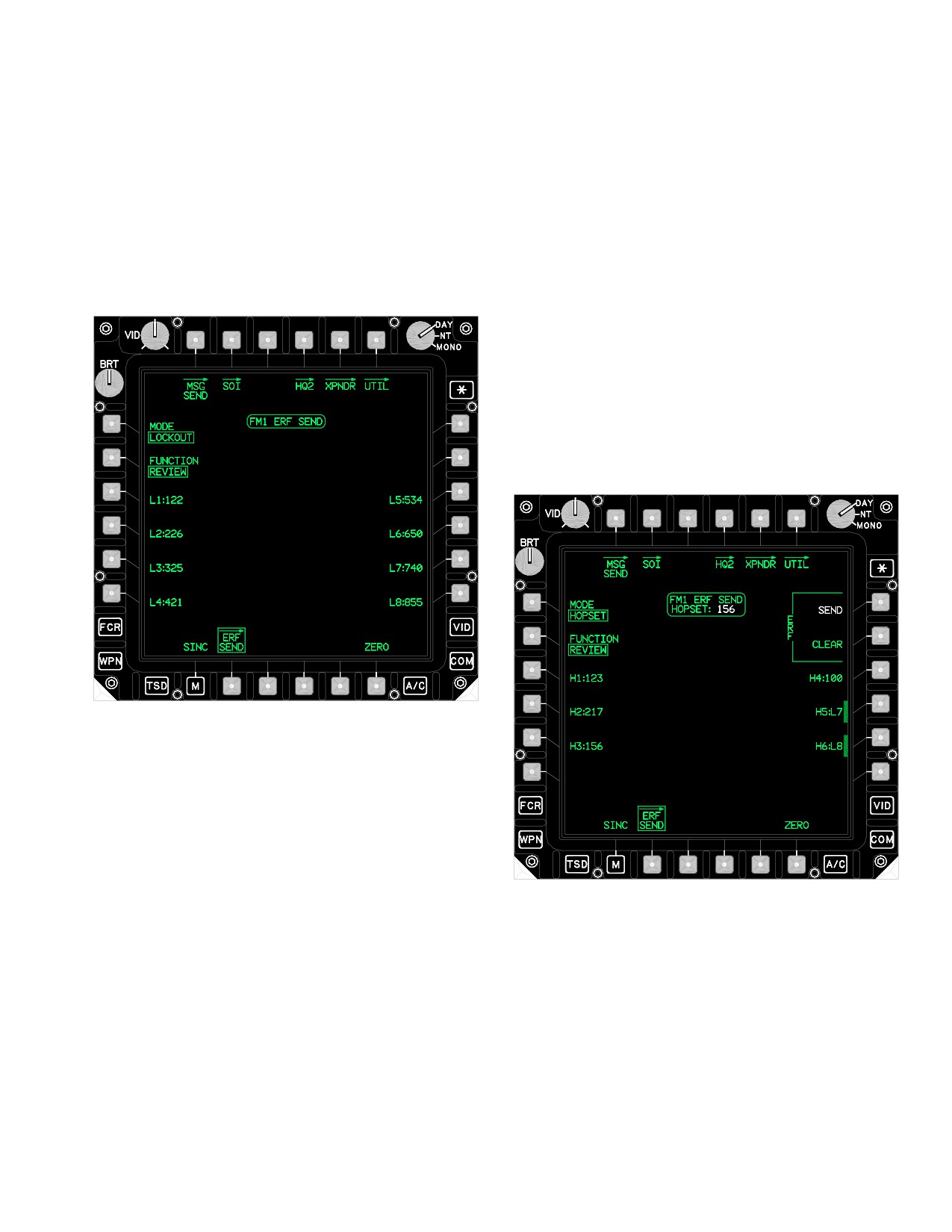
TM 1-1520-251-10
The ERF SEND page contains the following unique but-
3.37.4 ERF LOCKOUT Buttons. The ERF LOCKOUT
tons:
buttons provides the capability to select a lockout to be
transmitted through the ERF process. The current lockout
• L1
ERF MODE button
to be sent is displayed in the SEND LOCKOUT window.
• L2
ERF FUNCTION button
• L3-L6
ERF HOPSET/LOCKOUT buttons
3.37.5 ERF SEND Button. The ERF SEND button pro-
vides the capability to command the radio to transmit the
• R1
ERF SEND button
hopset or lockout selected for sending. Once the trans-
• R2
ERF CLEAR button
mission is complete the ERF SEND button is removed.
• R3-R6
ERF HOPSET/LOCKOUT buttons
3.37.6 ERF CLEAR. The ERF CLEAR button clears
the hopset or lockout that was selected for sending. The
ERF CLEAR button removes the ERF SEND button and
itself.
3.37.7 SEND HOPSET Window. The SEND HOPSET
window (fig 3-46) displays the hopset data in that is to be
transmitted through the ERF process with the selection of
the ERF SEND button.
LBA5215
Figure 3-45. ERF SEND Page - Lockout Mode
3.37.1 ERF MODE Button. The ERF MODE button op-
erates in two modes: HOPSET and LOCKOUT.
3.37.2 ERF FUNCTION. The ERF FUNCTION button
provides the capability to select REVIEW and DELETE
hopsets and lockouts, and COPY and EDIT functions for
LBA5216
hopsets.
Figure 3-46. ERF SEND Page - Hopset Send
3.37.3 ERF HOPSET Buttons. The ERF HOPSET but-
tons provides the capability to select a hopset to be trans-
mitted through the ERF process. The current hopset to be
3.37.8 SEND LOCKOUT Window. The SEND LOCK-
sent is displayed in the SEND HOPSET window and an
OUT window (fig 3-47) displays the lockout data in that is
intermittent beep will be heard until the hopset is sent or
to be transmitted through the ERF process with the selec-
cleared.
tion of the ERF SEND button.
Use or disclosure of this information is subject to the restriction(s) on the title page of this document.
3-33
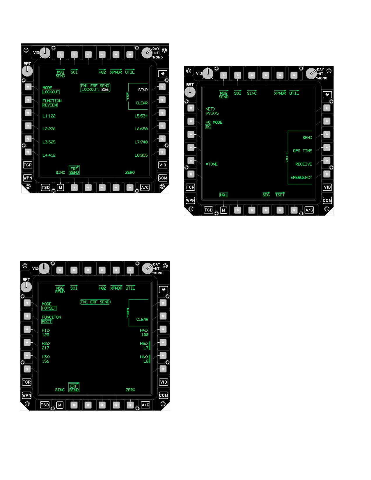
TM 1-1520-251-10
3.38 HQ1 (HAVE QUICK) PAGE
The HQ1 button (fig 3-49) displays the HQ1 page.
LBA5217
Figure 3-47. ERF SEND Page - Lockout Send
LBA5219
Figure 3-49. HQ1 Page
3.37.9 ERF SEND Page - Hopset Edit. The EDIT func-
tion is only available for hopsets (fig 3-48).
• L1
NET button
• L2
HQ MODE button
• L5
TONE button
• R3
TOD SEND button
• R4
TOD GPS TIME button
• R5
TOD RECEIVE button
• R6
TOD EMERGENCY button
• B4
SEG (Segment) button
• B5
TSET (Training Setup) button
3.38.1 NET Button. The net numbers enable multiple
station pairs to operate simultaneously using the same
Word of Day and Time of Day without interference.
3.38.2 HQ MODE Button. The HQ MODE button pro-
vides the capability to control the current mode. The but-
ton provides options of SC, FH, and TRNG (Training).
3.38.3 TONE Button. The TONE button enables crew
members to enable/disable the HAVE QUICK tones.
3.38.4
TOD SEND Button. The TOD SEND button
transmits TOD data. A tone in the headset sounds when
LBA5218
the TOD is transmitted. The TOD SEND button is not dis-
played when the HQ1 MODE is set to the HQ1 FH or HQ1
Figure
3-48.
ERF SEND Page - Hopset Edit
TRNG mode.
Use or disclosure of this information is subject to the restriction(s) on the title page of this document.
3-34
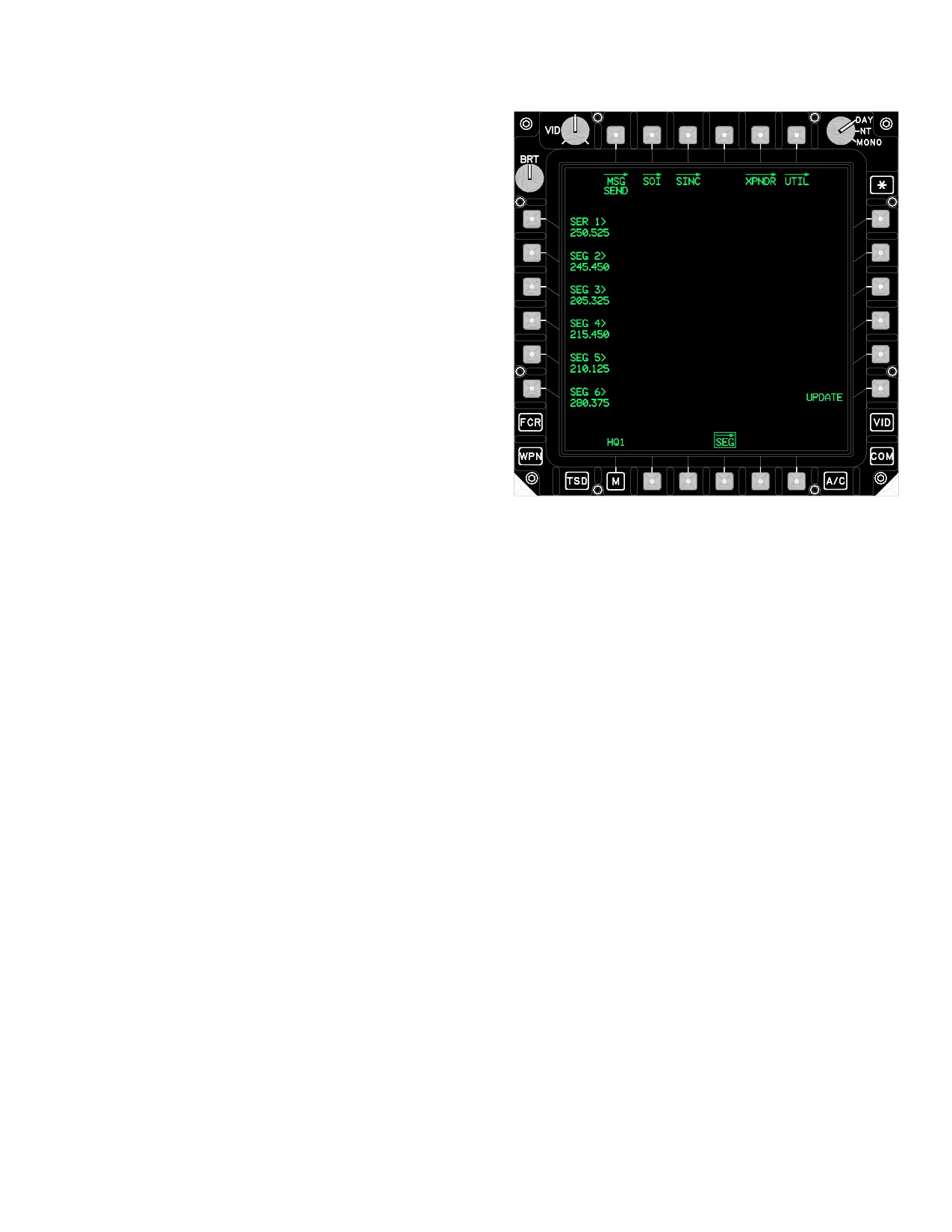
TM 1-1520-251-10
3.38.5 TOD GPS TIME Button. The TOD GPS TIME
button configures the UHF radio to accept the TOD as the
time from the EGI. The TOD GPS TIME button is not dis-
played when the HQ1 MODE is set to the HQ1 FH or HQ1
TRNG mode.
NOTE
When initiating the TOD RECEIVE button,
notify other crewmember to prevent inad-
vertent termination of reception.
3.38.6
TOD RECEIVE Button. The TOD RECEIVE
button configures the UHF radio to receive the TOD. A
tone is generated to provide the crew feedback with that
the reception was successful. The crew has the capability
to terminate the receive mode prior to timing out by press-
ing the TOD RECEIVE button again. The TOD RECEIVE
LBA5220
legend is not displayed when the HQ1 MODE is set to the
HQ1 FH or HQ1 TRNG modes.
Figure 3-50. HQ1 SEG Page
• L1-L6
SEG buttons
• R6
UPDATE button
3.38.7 TOD EMERGENCY Button. The TOD EMER-
GENCY button generates a pseudo TOD which can be
NOTE
utilized as a reference TOD when no other TOD is avail-
able. The TOD SEND button is selected to transmit the
The segments displayed on the segment
TOD EMERGENCY. The TOD EMERGENCY button is
page are not necessarily the segments ac-
not displayed when the HQ1 MODE is set to the HQ1 FH
tive in the UHF radio. The UPDATE button
or HQ1 TRNG modes.
on the HQ1 must be selected following mod-
ification of the segments on the SEG page
to transfer the modified segments to the
UHF radio.
3.38.8 SEG Page Button. The SEG button displays the
HQ1 SEG page.
3.39.1 SEG Buttons. The SEG buttons change any of
the six WOD segments. At least 1 segment must be
loaded into the UHF radio for FH operation. The SEG but-
tons are not selectable when the HQ1 MODE is set to the
3.38.9 TSET Page Button. The TSET button displays
HQ1 FH or HQ1 TRNG modes. Upon power up, the state
the HQ1 TSET page. See paragraph 3.40.
at last shutdown is restored if no DTC is present.
3.39.2
UPDATE Button. The UPDATE button com-
mands the system to load the current segments that are
3.39 HQ1 SEG PAGE
displayed on the SEG page into the radio. A tone is gener-
ated when a crewmember selects the UPDATE button as
a result of a valid WOD entry into the radio. The UPDATE
The HQ1 SEG button (fig 3-50) displays the HQ1 SEG
button is not displayed when the HQ1 MODE is set to the
page.
HQ1 FH or HQ1 TRNG modes.
Use or disclosure of this information is subject to the restriction(s) on the title page of this document.
3-35
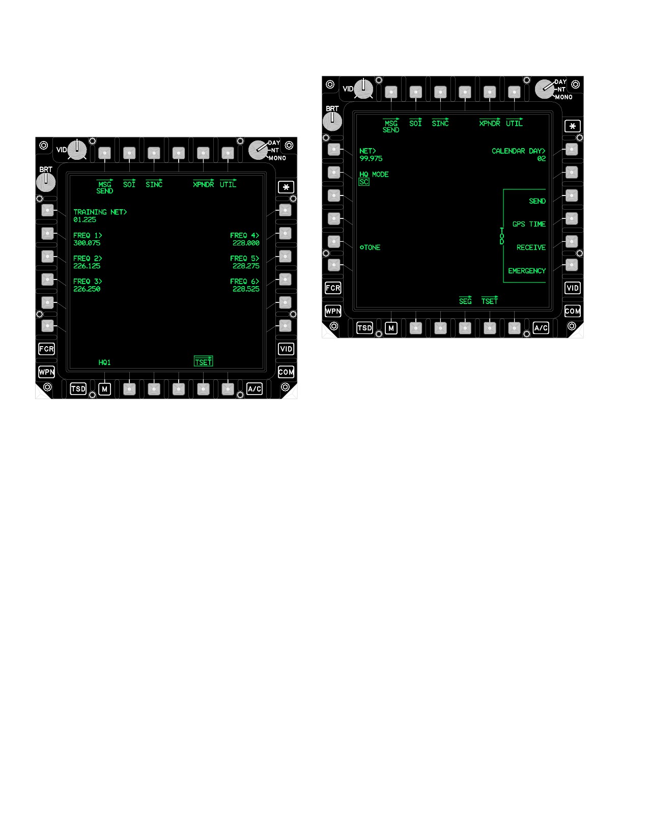
TM 1-1520-251-10
3.40 HQ1 TSET PAGE
The TSET button displays the HQ1 TSET page (fig 3-51).
LBA5222
Figure 3-52. HQ2 Page
The HQ2 page (fig 3-52) contains the following unique
LBA5221
buttons:
Figure 3-51. HQ1 TSET Page
• R1
CALENDAR DAY button
• B4
SEG (Segment) button
• B5
TSET (Training Setup) button
The HQ1 TSET page contains the following unique but-
tons:
3.41.1
CALENDAR DAY Button. The CALENDAR
DAY button provides the capability to change the calendar
• L1
TRAINING NET button
day. The calendar day is the internal date utilized by the
• L2-L4
FREQ buttons
UHF radio. When the WOD and CALENDAR DAY data
fields match, the associated segments become active, en-
• R2-R4
FREQ buttons
abling frequency hopping communication.
3.40.1 TRAINING NET Button.The TRAINING NET but-
3.41.2 SEG Page Button. The SEG button displays the
ton provides the capability to change the training net.
HQ2 SEG page.
3.40.2 FREQ Buttons. The FREQ buttons provide the
3.41.3 TSET Page Button. The TSET button displays
capability to change the six training frequencies.
the HQ2 TSET page.
3.41 HQ2 PAGE
3.42 HQ2 SEG PAGE
The HQ2 button (fig 3-52) displays the HQ2 page.
The SEG button (fig 3-53) displays the HQ2 SEG page.
Use or disclosure of this information is subject to the restriction(s) on the title page of this document.
3-36
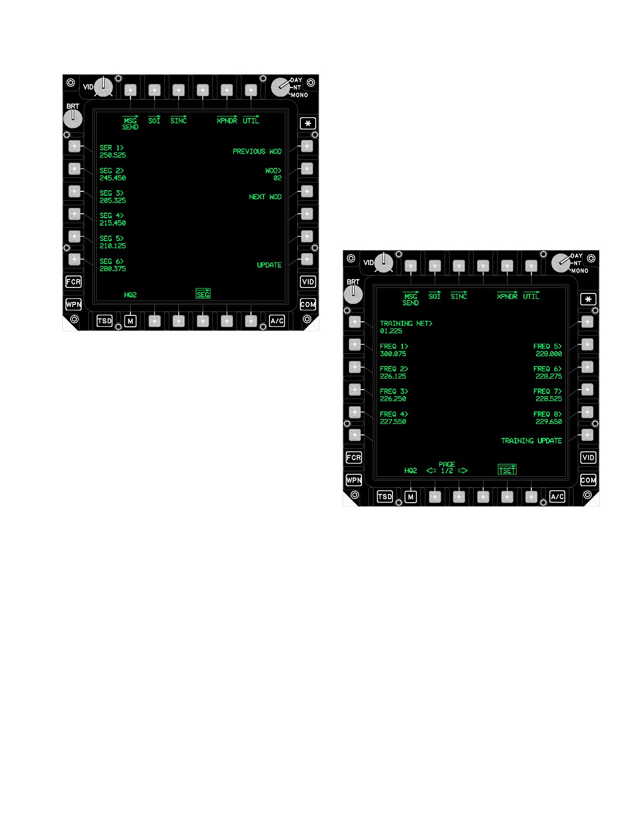
TM 1-1520-251-10
3.42.5
UPDATE Button. The UPDATE button com-
mands the system to load the current segments that are
displayed on the SEG page into the radio. A tone is gener-
ated when a crewmember selects the UPDATE button as
a result of a valid WOD entry into the radio. The UPDATE
button is not displayed when the HQ2 MODE is set to the
HQ2 FH or HQ2 TRNG modes.
3.43
(HQ2) TSET PAGE
The HQ2 TSET button (fig 3-54) displays the HQ2 TSET
page.
LBA5223
Figure 3-53. HQ2 SEG Page
The SEG page (fig 3-53) contains the following unique
buttons:
• L1-L6
SEG buttons
• R1
PREVIOUS WOD button
• R2
WOD button
• R3
NEXT WOD button
3.42.1 SEG Buttons. The SEG buttons change any of
the six WOD segments. At least one segment must be
LBA5224
loaded into the UHF radio for FH operation. The SEG but-
tons are not selectable when the HQ2 MODE is set to the
FH or TRNG modes. Upon power up, the state at last
Figure 3-54. HQ2 TSET Page
shutdown is restored if no DTC is present.
3.42.2
PREVIOUS WOD Button. The PREVIOUS
The HQ2 TSET page button (fig 3-54) contains the follow-
WOD button is used to decrement and display 1 of the 6
ing unique buttons:
Word of Days that is loaded into the system.
• L1
TRAINING NET button
3.42.3 WOD Button. The WOD button determines the
• L2-L5
FREQ buttons
Word of Day assignment. When the CALENDAR DAY and
a WOD that have been loaded into the radio match, the
• R2-R5
FREQ buttons
associated segments become active, enabling FH com-
• R6
TRAINING UPDATE button
munications. The radio knows which WOD to activate by
• B2
PAGE DOWN button
the number assigned to it during loading.
• B3
PAGE UP button
3.42.4 NEXT WOD Button. The NEXT WOD button is
used to increment and display 1 of the 6 Word of Days that
3.43.1 TRAINING NET Button. The TRAINING NET
is loaded into the system.
button provides the capability to change the training net.
Use or disclosure of this information is subject to the restriction(s) on the title page of this document.
3-37
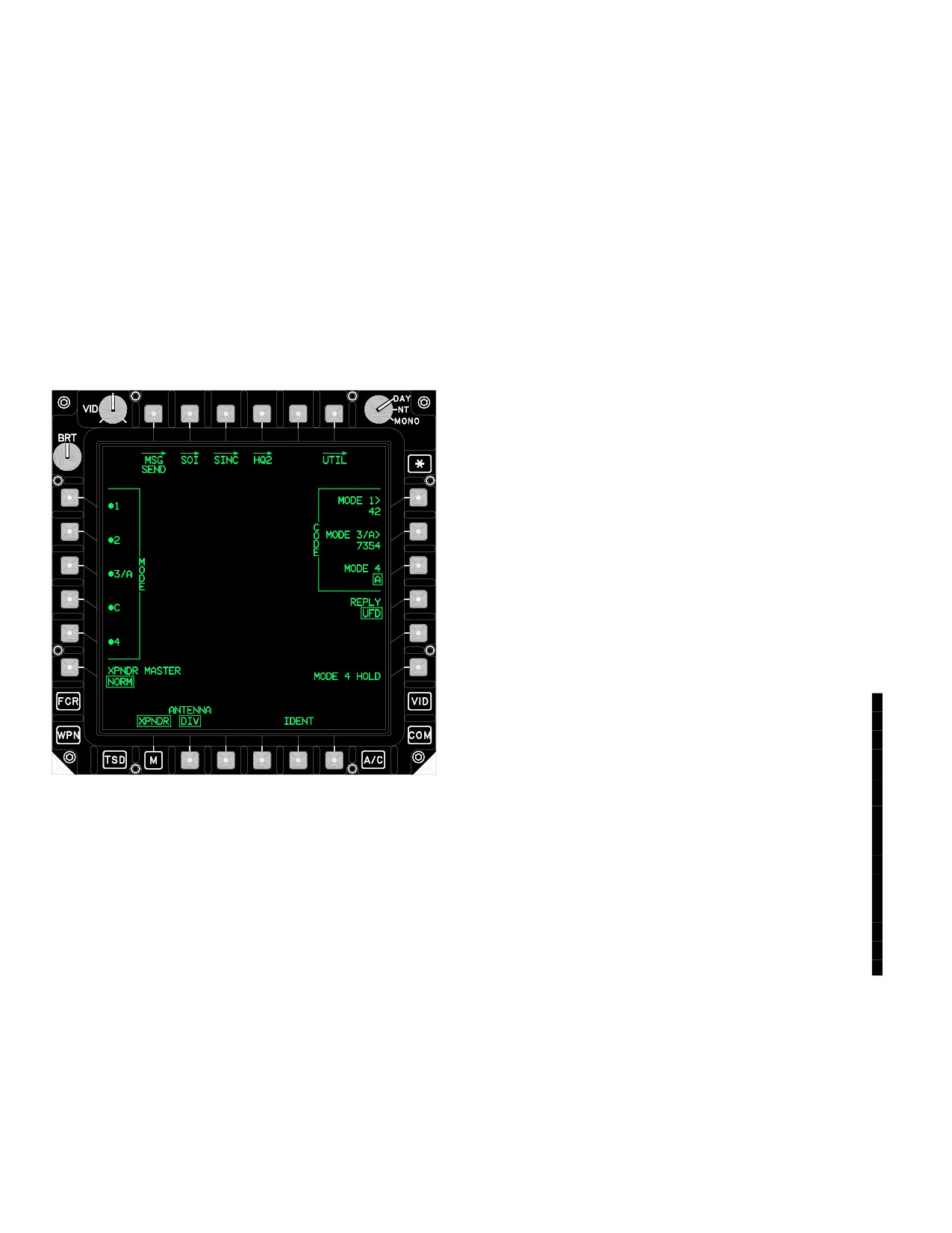
TM 1-1520-251-10
3.43.2 FREQ Buttons. The FREQ buttons provide the
• B2
ANTENNA button
capability to change the 16 training frequencies.
• B5
IDENT button
3.43.3 TRAINING UPDATE Button. The TRAINING
3.44.1 MODE 1 Button. The MODE 1 button enables/
UPDATE button commands the system to load the train-
disables MODE 1
ing frequencies that are displayed on the TSET page into
3.44.2 MODE 2 Button. The MODE 2 button enables/
the UHF radio. A tone is generated when the crew selects
disables MODE 2
the TRAINING UPDATE button.
3.44.3 MODE 3/A Button. The MODE 3/A button en-
3.43.4 PAGE UP and PAGE DOWN Buttons. Allows
ables/disables Mode 3/A. When MODE 3/A button is se-
selection between two pages of training frequencies.
lected OFF, the MODE C button is automatically turned
3.44 XPNDR PAGE
OFF.
3.44.4 MODE C Button. The MODE C button enables/
The XPNDR page (fig 3-55) provides the capability to ac-
disables the MODE C transmission. When MODE C but-
cess transponder functions.
ton is selected ON, the MODE 3/A button is automatically
turned ON.
3.44.5 MODE 4 Button. The MODE 4 button enables/
disables Mode 4. The Mode 4 Code data field on the UFD
is updated when the mode has been been changed. The
Mode 4 warning is a tone which is generated by the
XPNDR in response to a Mode 4 incompatible code.
3.44.6 XPNDR MASTER Button. The XPNDR MAS-
TER button toggles between Standby (STBY) and Normal
(NORM) modes.
3.44.7 CODE MODE 1 Button. The CODE MODE 1 but-
ton provides the capability to change the MODE 1 code.
NOTE
• Mode 2 must be manually entered on the
face of the APX - 100.
• Due to the APX-118 hardware and soft-
ware fielding plan, an interim alternative
MODE 2 entry procedure must be per-
formed.
LBA5225
3.44.7A APX - 118 CODE MODE 2 Entry.
1. MODE 3A - Select.
Figure 3-55.
XPNDR Page
NOTE
If the assigned mode 2 code is not entered
The XPNDR page contains the following unique buttons:
within 15 seconds,
2222 will be displayed as
• L1
MODE 1 button
the current MODE 3/A code.
• L2
MODE 2 button
2. Mode 2 code - Enter “2222” followed by as-
• L3
MODE 3/A button
signed mode 2 code, within 15 seconds (exam-
• L4
MODE C button
ple: 2222xxxx).
• L5
MODE 4 button
3.44.8 CODE MODE 3/A Button. The CODE MODE 3/A
• L6
XPNDR MASTER button
button provides the capability to change the MODE 3/A code.
• R1
CODE Mode 1 button
3.44.9 CODE MODE 4 Button. The CODE MODE 4 but-
• R2
CODE Mode 3/A button
ton toggles between XPNDR code MODE 4 A and B. The
• R3
CODE Mode 4 button
code Mode 4 data field is updated when the code has been
• R4
REPLY button
changed. The CODE MODE 4 button is not displayed if the
• R6
MODE 4 HOLD button
KIT-1C computer is not installed.
Use or disclosure of this information is subject to the restriction(s) on the title page of this document.
3-38
Change 3
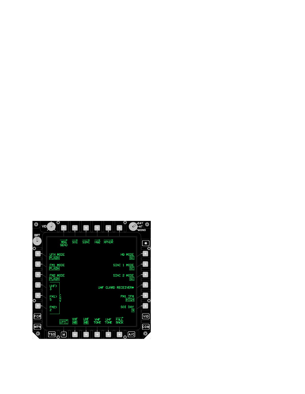
TM 1-1520-251-10
3.44.10 REPLY Button. The REPLY button controls
The COM UTIL page contains the following buttons:
the feedback the crew will receive when the XPNDR sys-
• L1
UHF MODE button
tem responds to a Mode 4 interrogation. The button pro-
vides options of REPLY UFD/AUDIO, REPLY UFD, and
• L2
FM1 MODE button
REPLY OFF.
• L3
FM2 MODE button
• L4
CNV UHF button
3.44.11 MODE 4 HOLD Button. Selecting the MODE 4
HOLD button prevents erasure of the Mode 4 Codes in
• L5
CNV FM1 button
the Kit-1C computer when the aircraft is on the ground
• L6
CNV FM2 button
and power is removed from the XPNDR system. The
• R1
HQ MODE button
MODE 4 HOLD button is not displayed if the Kit-1C com-
puter is not installed.
• R2
SINC 1 MODE button
• R3
SINC 2 MODE button
3.44.12 ANTENNA Button. The ANTENNA button al-
• R4
UHF GUARD RECEIVER button
lows selection of the antenna used for transmitting and re-
• R5
FM1 IFM button
ceiving XPNDR interrogations. The button provides op-
tions of ANTENNA TOP, ANTENNA Diversity (DIV), and
• R6
SOI DAY button
ANTENNA Bottom (BOT).
• B2
VHF Bandwidth button
• B3
UHF Bandwidth button
3.44.13 IDENT Button. The IDENT button commands
the transponder to transmit Modes 1, 2, and 3/A if ON.
• B4
VHF TONE button
The IDENT button is not displayed if XPNDR MASTER
• B5
UHF TONE button
button is in STBY mode or if Modes 1, 2, and 3/A are all
• B6
FALL BACK button
OFF, regardless of the XPNDR MASTER mode.
3.45.1 UHF MODE Button. The UHF MODE button
3.45 COMMUNICATIONS UTILITY (UTIL) PAGE
controls the operation of the UHF KY-58. The button pro-
vides options of CIPHER, PLAIN, and RECEIVE.
The COM UTIL page (fig 3-56) provides the capability to
access communication functions.
3.45.2 FM1 MODE Button. The FM1 MODE button
controls the operation of the FM1 embedded COMSEC
device. The button provides options of CIPHER, PLAIN,
and RECEIVE.
3.45.3 FM2 MODE Button. The FM2 MODE button
controls the operation of the FM2 embedded COMSEC
device. The button provides options of CIPHER, PLAIN,
and RECEIVE.
NOTE
When CNVs are loaded into the radios,
there is no indication in the crewstation as to
which CNV was loaded into which radio.
3.45.4 CNV UHF Button. The CNV UHF button pro-
vides the capability to change the UHF crypto net variable.
3.45.5 CNV FM1 Button. The CNV FM1 button pro-
vides the capability to change the FM1 embedded COM-
SEC device’s crypto net variable.
LBA0415A
3.45.6 CNV FM2 Button. The CNV FM2 button pro-
vides the capability to change the FM2 embedded COM-
Figure 3-56. COM UTIL Page
SEC device’s crypto net variable.
Use or disclosure of this information is subject to the restriction(s) on the title page of this document.
3-39
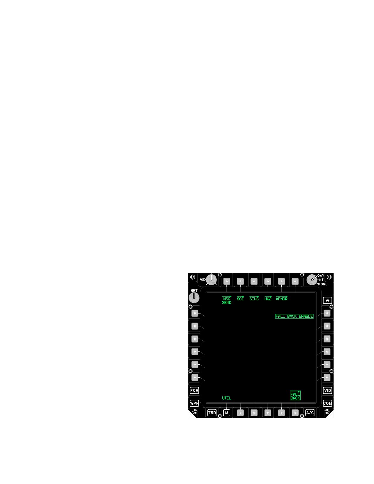
TM 1-1520-251-10
3.45.7 HQ MODE Button. The HQ MODE button pro-
NOTE
vides the capability to control the current mode. The but-
• The VHF TONE button causes the tone
ton provides options of SC, FH, and TRNG (Training).
to be transmitted over the air.
• When Tacfire protocol is active, an audi-
ble tone will be transmittted over the air.
3.45.8 SINC 1 MODE Button. The SINC 1 MODE but-
ton provides the capability to control the mode of the se-
• When Longbow (AFAPD) protocol is ac-
lected FM1 radio. The button provides options of SC, FH,
tive, no audible tone and a “dead carrier”
and FH/M.
will be transmitted over the air.
3.45.16 UHF TONE Button. The UHF TONE button
enables the UHF tone. The tone may be used to set the
3.45.9 SINC 2 MODE Button. The SINC 2 MODE but-
volume and perform maintenance on the UHF radio.
ton provides the capability to control the mode of the se-
When a crewmember selects the UHF TONE button, the
lected FM2 radio. The button provides options of SC, FH,
radio generates the tone for 5 seconds.
and FH/M.
NOTE
The UHF TONE button causes the tone to
3.45.10 UHF GUARD RECEIVER Button. The UHF
be transmitted over the air.
GUARD RECEIVER button enables/disables the dedi-
cated guard receiver. This button is disabled and barri-
3.45.17 FALL BACK Page Button. The FALL BACK
ered if the UHF radio is tuned to the Guard frequency.
page is accessed by selecting the FALL BACK button on
the COM UTIL page. See paragraph 3.46.
3.45.11 FM1 IFM Buttons. The FM1 IFM button con-
3.46 FALL BACK PAGE
trols the Improved Frequency Modulation amplifier of the
FM1 radio. The button provides options of HIGH, NORM,
The FALL BACK page (fig 3-57) provides the capability to
LOW, and OFF.
set the system into a FALL BACK mode in the event of
Communication Interface Unit (CIU) failure.
3.45.12 SOI DAY Button. The SOI DAY button pro-
vides the capability to toggle between the two different
days of SOI data that are displayed within the communica-
tions subsystem.
3.45.13 VHF Bandwidth Button. The VHF Bandwidth
button provides the capability to toggle between the WB
(Wide Bandwidth) and NB (Narrow Bandwidth) modes.
3.45.14 UHF Bandwidth Button. The UHF Bandwidth
button provides the capability to toggle between the WB
(Wide Bandwidth) and NB (Narrow Bandwidth) modes.
3.45.15 VHF TONE Button. The VHF TONE button en-
ables the VHF tone. The tone may be used to set the vol-
ume and perform maintenance on the VHF radio. When a
LBA2574A
crewmember selects the VHF TONE button, the radio
generates the tone for 5 seconds.
Figure 3-57. FALL BACK Page
Use or disclosure of this information is subject to the restriction(s) on the title page of this document.
3-40
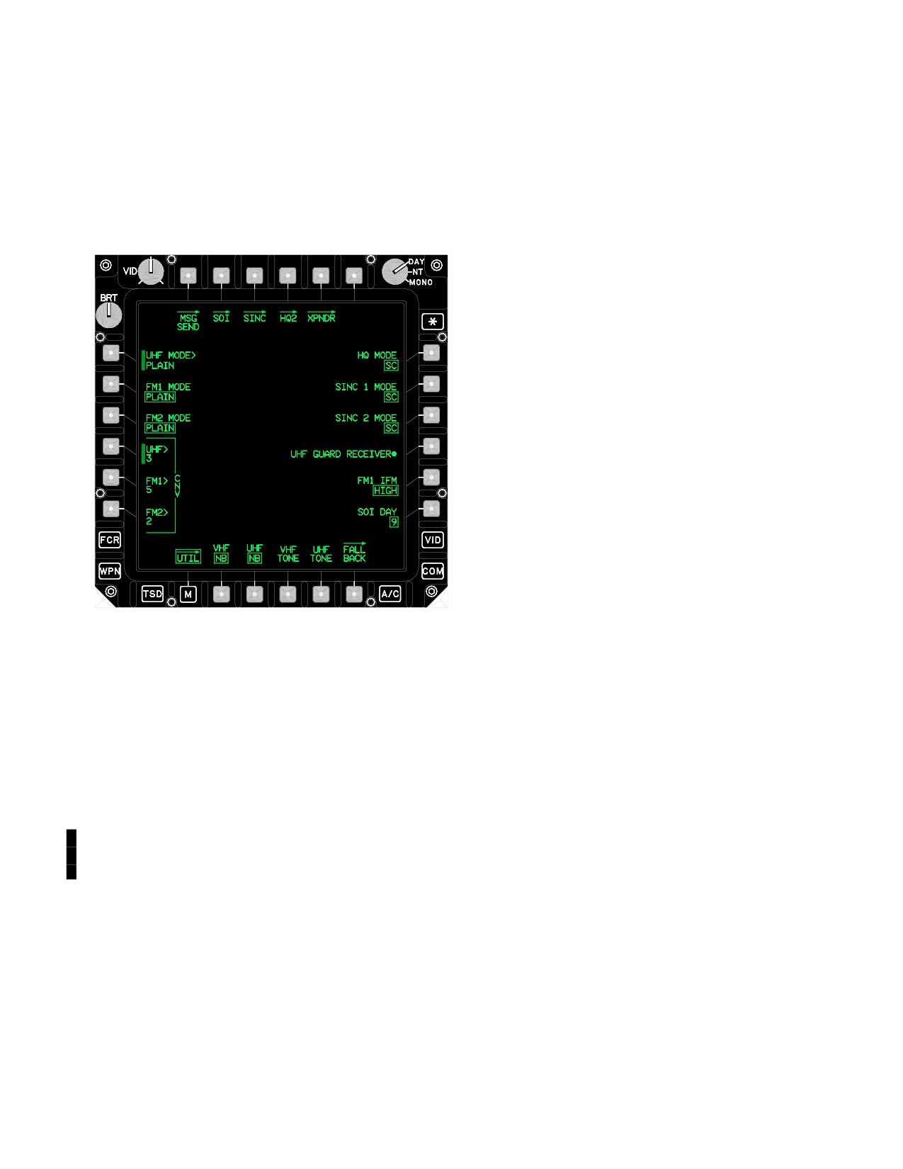
TM 1-1520-251-10
3.46.1 FALL BACK Enable Button. The FALL BACK
• UHF radio will go secure if a KY- 58 is installed and
enable button (fig 3-58) provides the capability to mode
turned ON. If the FILL position selected is not
the communication subsystem to a Fall Back mode. When
loaded with a CNV, only plain radio reception is
a crewmember selects the FALL BACK enable button,
available. Attempting to transmit will result in a
the system is set to the FALL BACK mode and the UFD
steady tone.
displays the advisory message FALL BACK.
• ICS communication between the Pilot and CPG is
moded to Hot MIC (TEMPEST MIC Only).
3.47 ARC-164 HAVE QUICK (HQ) PROCEDURES
NOTE
HQ2 is standard. If HQ1 is installed, the air-
craft will configure automatically. HQ1 has
only one WOD and six TSET (training) fre-
quencies.
3.47.1 Automatic Loading HQ Data.
NOTE
• When using the DTU to load HQ data into
the aircraft, all HQ data is loaded.
• TSET HQ data must be entered manually
into the aircraft. There is no DTU upload
capability.
1. DTU - Select MASTER LOAD.
LBA2575A
or
Figure
3-58.
UTIL Page - FALL BACK Enable
2. DTU DATA COMMUNICATIONS - Select ALL
or MWOD.
3.47.2 Manual Loading HQ Data.
The following functions are moded with the selection of
the FALL BACK mode:
NOTE
• Always use NEXT WOD or PREVIOUS
NOTE
WOD when indexing between WOD seg-
• The pilot and CPG floor, push to talk
ment lists. DO NOT use the WOD entry
switches are inoperative when operating
with the keyboard as this only renames
the CIU in the Fall Back mode.
the WOD segment list currently dis-
played.
• Operating in the Fall Back mode requires
• The last two digits of the first segment in
a TEMPEST microphone to communi-
any WOD specifies the hoprate in the FH
cate on either intercom or the the radios.
mode:
xxx.x00 (slowest)
• Pilot is RTS to the UHF radio.
xxx.x25
• Pilot and CPG radio monitor levels are defaulted
xxx.x50
to a fixed level.
xxx.x75 (fastest)
Best results for FH CIPHER (secure), use
• CPG is RTS to the VHF radio.
hoprates between xxx.x00 or xxx.x25.
Use or disclosure of this information is subject to the restriction(s) on the title page of this document.
Change 4
3-41
TM 1-1520-251-10
• The calendar day (via GPS/TOD RE-
9. NET - Enter.
CEIVE/CALENDAR DAY) number speci-
fies which WOD segment list the radio
10. CALENDAR DAY - Enter.
will use.
11. HQ2 - Deselect when complete.
• Operational NET numbers are allocated
as follows:
or
yy.y00 - HQ1 Mode
yy.y25 - HQ2 NATO usage
If TSET values are to be entered, perform
yy.y50 - HQ2 non-NATO countries
the following:
Where y is any number 0 to 9. All other
operational NET number combinations
12. HQ2 - Select.
are illegal.
13. TSET - Select.
• Training NET numbers are allocated as
follows:
14. Enter all TSET segments 1 thru 16 (1 thru 6 if
When using WOD segment lists for train-
HQ1).
ing (first segment in a given WOD must
be 300.0xx), NET numbers are 00.z00.
15. TRAINING NET - Enter.
Where z is any number 0 to 4; z specifies
which of the frequencies in the WOD seg-
16. TSET - Deselect.
ments hopping will start on.
When using the TSET segment list for
17. HQ2 - Deselect.
training, NET numbers are 0z.z25. The
suffix of 25 specifies that the TSET fre-
3.47.3 Update WOD or TSET.
quency list in the radio is to be used for
hopping. The z.z is any number 0.0 to 1.5
1. HQ2 - Select.
and designates which of the frequencies
in the list will be used to start hopping.
2. SEG - Select.
1.
COM - Select.
3. Use NEXT WOD or PREVIOUS WOD to index
desired WOD segment list.
2.
HQ2 - Select.
4. UPDATE - Press.
3.
SEG - Select.
or
4.
WOD number - Enter as necessary.
If TSET frequencies are to be updated, per-
form the following:
5.
Enter all WOD segments 1 through 6.
5. HQ2 - Select.
6.
Use NEXT WOD or PREVIOUS WOD buttons to
6. TSET - Select.
index to next available WOD storage location.
7. TRAINING UPDATE - Press.
7.
Repeat steps 4 through 6 as necessary until all
WOD segments have been entered.
8. TSET - Deselect.
8.
SEG - Deselect.
9. HQ2 - Deselect.
Use or disclosure of this information is subject to the restriction(s) on the title page of this document.
3-42
Change 2
TM 1-1520-251-10
3.47.4 Receive TOD Signal.
3.48 ARC-201D SINCGARS PROCEDURES
1. HQ2 - Select.
NOTE
• Selections on the SINC page take 3 to 4
2. TOD RECEIVE - Select, can now receive TOD
seconds to complete in changing the
for the next 60 seconds.
modes of the ARC-201D radio. DO NOT
make a second or subsequent selection
3. HQ2 - Deselect.
until the first selection OPERATION IN
PROGRESS is complete.
3.47.5 Create Emergency TOD.
• In order to use SINCGARS frequency
1. HQ2 - Select.
hopping, the ARC-201D radio must be
loaded with the required hopsets and
2. CALENDAR DAY - Enter.
lockout sets.
• In order to send or receive an ERF, a hop-
3. TOD EMERGENCY - Press.
set must be stored in location 1 in the
ARC-201D radio.
4. HQ2 - Deselect.
•
An ERF procedure (ERF SEND or ERF
3.47.6 Create TOD.
RECEIVE) WILL NOT work correctly if
the MAN and CUE frequencies are the
1. HQ2 - Select.
same and the radio has been tuned to the
MAN frequency; either in SC or FH MAN.
Avoid setting the same frequency for
2. TOD GPS TIME - Press.
MAN and CUE.
3. HQ2 - Deselect.
3.48.1 Automatic Loading of SINCGARS Data.
3.47.7 Send TOD.
NOTE
1. HQ2 - Select.
The DTU will automatically load the initial
power-up, MAN, and CUE frequencies for
2. TOD SEND - Press.
each radio. It WILL NOT load the hopset
and lockout set data. This must be done di-
3. HQ2 - Deselect.
rectly into each radio.
3.47.8 Activation of HAVEQUICK (Frequency Hop-
1. DTU - Select MASTER LOAD.
ping).
2. DTU DATA COMMUNICATIONS - Select ALL.
1. Automatic load HQ data (para 3.47.1).
3.48.2 Manual Loading of SINCGARS Data.
or
1. COM - Select.
2. Manual load HQ data (para 3.47.2).
2. SINC - Select.
3. Update WOD or TSET segments in radio (para
3.47.3).
3. RADIO - Select FM1 or FM2 as desired.
4. Radio has TOD - Verify.
4. MAN frequency - Enter.
5. COM UTIL - Select.
5. CUE frequency - Enter.
6. HQ MODE - Select FH.
6. HOPSET - Select to verify loaded hopsets.
7. COM UTIL - Deselect.
7. HOPSET - Deselect.
Use or disclosure of this information is subject to the restriction(s) on the title page of this document.
3-43
TM 1-1520-251-10
8. Repeat steps 3 through 7 for other FM radio, as
9. SINC - Deselect.
desired.
3.48.4 ERF Send.
9. SINC - Deselect.
1.
SINC - Select.
3.48.3
Set Base Time-of-Day (TOD)/NET (Hopset)
Synchronization.
2.
Automatic Loading of SINCGARS data
(para 3.48.1).
NOTE
or
• To ensure all aircraft will use approxi-
mately the same TOD within ± 4 seconds,
3.
Manual Loading of SINCGARS Data
select the CLOCK GPS TIME button.
(para 3.48.2).
Other methods are permissible but may
require more detailed coordination; any
4.
RADIO - Select FM1 or FM2 as desired.
method used must ensure that the base
TOD is within ± 4 seconds.
5.
HOPSET - Select MAN.
• The base TOD only needs to be set once,
but the ERF SEND/RECEIVE procedure
6.
SINC 1 or 2 MODE - Select FH/M.
for final synchronization must be accom-
plished with each different Net Control
7.
ERF SEND - Select.
Station (Hopset) that will be used.
8.
MODE - Select desired mode, hopset or lock-
• After TOD synchronization, if the
out.
ARC-201D radio battery backup is
installed with good batteries, the radio will
9.
Select desired Hopset or Lockout Set.
hold synchronization for approximately
24 hours after aircraft power is off.
10.
SEND - Select.
1.
SINC - Select.
11.
Repeat steps 8 through 10 as necessary to com-
plete ERF transfer for all hopsets and lockout
2.
RADIO - Select FM1 or FM2 as desired.
sets desired.
3.
GPS TIME - Press.
12.
ERF SEND - Deselect.
or
13.
SINC - Select.
4.
DATE/TIME - Enter day of month, hour and
3.48.5 ERF Receive.
minutes in 24 hour format.
1. SINC - Select.
If NET (Hopset) Synchronization only is re-
quired, only the following is necessary:
2. RADIO - Select desired FM radio.
5. RADIO - Select FM1 or FM2, if required.
3. HOPSET - Select MAN
6. Execute ERF SEND/ERF RECEIVE procedure,
4. SINC 1 or 2 MODE - Select FH.
as appropriate, to complete synchronization.
5. ERF REC - Select.
7. Repeat step 6, as necessary, for each different
Net Control Station (Hopset) that will be used.
6. MODE - Select desired mode, hopset or lock-
out, as directed.
8. Repeat steps 2 through 7 for other FM radio, as
desired.
7. RECEIVE - Select.
Use or disclosure of this information is subject to the restriction(s) on the title page of this document.
3-44
TM 1-1520-251-10
8. If hopset data received - Store in desired stor-
or
age location.
2. DTU DATA COMMUNICATIONS - Select ALL
or
or IDM.
9. If lockout set data received - STORE Select.
3.50.2 Manual Loading of IDM NET Data.
10. RECEIVE - Deselect.
1. COM - Select.
11. Repeat steps 8 or 9 as necessary to complete
2. Select desired preset.
ERF transfer for all hopsets and lockout sets de-
sired.
3. NET - Select.
12. ERF REC - Deselect.
4. Select any subscriber location.
13. SINC - Deselect.
5. EDIT - Select.
3.48.6 Activate Frequency Hopping Mode.
6. Enter the following as desired:
1. SINC - Select.
Net Parameters
Subscriber Parameters
UNIT ID
MEMBER CALL SIGN
2. RADIO - Select FM1 or FM2 as desired.
CALL SIGN
MEMBER SUBSCRIBER
3. NET (Hopset) Synchronization (para 3.48.3), -
VHF FREQ
Verify complete.
UHF FREQ
4. HOPSET - Select desired hopset.
FM FREQ
IDM NET
ORIG (Ownship Subscriber ID)
5. SINC 1 or 2 MODE - Select FH or FH/M.
7. EDIT - Deselect.
6. SINC - Deselect.
8. Verify subscriber added/edited is designated in
3.49
COMSEC OPERATION
ZN or TM, as desired.
1. COM UTIL - Select.
NOTE
2. Enter CNV for UHF, FM1 and FM2, as desired.
• A maximum of 15 subscribers/team
members of which 8 can be zone mem-
3. UHF - Select and choose PLAIN or CIPHER, as
bers (including ownship) are allowed in
desired.
any given net.
• Valid subscriber numbers range from
4. FM1 - Select and choose PLAIN or CIPHER, as
0 - 39, A - 3I.
desired0.
9. Repeat steps 6 through 8 as desired for other
5. FM2 - Select and choose PLAIN or CIPHER, as
subscriber data only.
desired.
10. MODEM - Select.
6. COM UTIL - Deselect.
NOTE
3.50
IMPROVED DATA MODEM NET SETUP
Lower baud rates for the IDM may improve
3.50.1 Automatic Loading of IDM NET Data.
long range digital communications.
1. DTU - Select MASTER LOAD.
11. Enter modem parameters as desired.
Use or disclosure of this information is subject to the restriction(s) on the title page of this document.
3-45
TM 1-1520-251-10
12. MODEM - Deselect.
13. NET - Deselect.
14. Repeat steps 2 through 13 for additional presets
as desired.
15. Tune desired radio and verify frequency and Net
assignment on UFD.
3.51 TRANSMITTING AIR FORCE APPLICATION
PROGRAM DEVELOPMENT (AFAPD) PROTOCOL
MESSAGES
NOTE
• The Longbow Protocol is sometimes re-
ferred to as the AFAPD protocol.
• RTS must be used to select a radio with a
valid IDM Net before transmission. The
SEND selection will not be displayed if
the selected radio does not have a valid
IDM Net.
• IDM messages capable of being trans-
mitted from the TSD or FCR displays will
only have the SEND selection displayed
if the subscriber(s) have been selected.
Subscriber(s) will only be displayed on
these displays if they have been desig-
nated as zone members.
Use or disclosure of this information is subject to the restriction(s) on the title page of this document.
3-46
TM 1-1520-251-10
3.52 TO TRANSMIT LONGBOW MESSAGES
TYPE OF MESSAGE
MPD SELECTIONS/ACTIONS
TO SEND MESSAGE
RF Target Handover
After FCR scan, on FCR display
Select zone member, then SEND.
select NTS. Select RFHO.
FCR Targets - All
TSD RPT TGT ALL
Select zone member, then SEND.
FCR Targets - Priority
TSD RPT TGT PRI
Select zone member, then SEND.
FCR Targets - Single or Multiple
TSD RPT TGT Cursor select single
Select zone member, then SEND.
or multiple FCR target icons
Shot At - All
TSD RPT BDA ALL
Select zone member, then SEND.
Shot At - Ownship
TSD RPT BDA OWN
Select zone member, then SEND.
Mode MSG to SEND
Shot At - Query
TSD RPT BDA OWN
Select zone member, then SEND.
Mode MSG to RQST
Pres Posn Report
TSD RPT PP
Select zone member, then SEND.
Mode MSG to SEND
Pres Posn Query
TSD RPT PP
Select zone member, then SEND.
Mode MSG to RQST
FARM Report
TSD RPT FARM
Select zone member, then SEND.
Mode MSG to SEND
FARM Query
TSD RPT FARM
Select zone member, then SEND.
Mode MSG to RQST
Single Stored Target/Threat
TSD THRT XMIT
SEND.
Use cursor to select or point data
entry method to select target or
threat
Single Waypoint/Hazard
TSD WPT XMIT
SEND.
Use cursor to select or point data
entry method to select
waypoint/hazard
Single Control Measure
TSD WPT XMIT
SEND.
Use cursor to select or point data
entry method to select control
measure
Zones - Priority Fire
TSD/ ATK ZN PF
SEND.
Zones - No Fire
TSD/ ATK ZN NF
SEND.
Zones - All
TSD/ ATK ZN BOTH
SEND.
Freetext
COM IDM FREETEXT
SEND.
Enter freetext
Waypoints file
COM IDM CURR MISSION
SEND.
WAYPOINTS
Routes file
COM IDM CURR MISSION
SEND.
Select ROUTE ALL, ROUTE
Select ALL, deselect ROUTE
Single route
COM IDM CURR MISSION
SEND.
Select ROUTE, ROUTE Select
desired route, deselect ROUTE
Laser codes
COM IDM CURR MISSION
SEND.
LASER CODES
Comm Data All
COM IDM ALL IDM/CEOI
SEND.
Use or disclosure of this information is subject to the restriction(s) on the title page of this document.
3-47
TM 1-1520-251-10
3.52 TO TRANMIT LONGBOW MESSAGES (contin-
ued)
Control Measures file
COM IDM CURR MISSION
SEND.
CONTROL MEASURES
Boundry/Phase Lines file
COM IDM CURR MISSION
SEND.
LINES
Engagement Areas file
COM IDM CURR MISSION
SEND.
AREAS
Stored Targets/Threats file
COM IDM CURR MISSION
SEND.
TGT/THRT
Current Mission - All
COM IDM CURR MISSION
SEND.
ALL
MISSION 1 - All files
COM IDM MISSION 1
SEND.
MISSION 2 - All files
COM IDM MISSION 2
SEND.
3.53 ATHS - TACFIRE IMPROVED DATA MODEM
12 - 48 (1 - 4 TACFIRE radios) previously received ATHS -
TACFIRE messages. The system also supports the shoot-
er/designator execution of a digital remote HELLFIRE
3.53.1
ATHS - TACFIRE MISSION CAPABIL-
mission and other airborne fire missions specifying rock-
ITIES. The IDM (MD - 1295/A Processor Interface Unit
ets, gun or HELLFIRE direct. The ATHS - TACFIRE sup-
[PIU] processes AFAPD (LONGBOW) and TACFIRE pro-
ports digital artillery fire missions as the Forward Artillery
tocol messages. The AH-64D’s 1553B bus integrated
Aerial Observer (FAAO) and transmits/receives spot situ-
TACFIRE protocol is programmed to continuously receive
ation reports, battle damage assessments, and casualty
and share dynamic data to and from the bus. Data from
reports. Team situational awareness capabilities are en-
the bus is automatically input into many of the data fields
hanced by the ability to track team member Fuel, Ammo,
that comprise the various messages. Received data is
Rockets, and Missile (FARM) status along with the ability
placed on the bus for SP, DP, and WP usage e.g. ATHS -
to track the present position of up to 15 team members per
TACFIRE target grid coordinate translated to 1553B T - 50
query.
target data and remote Hellfire automatic weapon mod-
ing. Specific to the AH - 64D’s TACFIRE integration, the
term ATHS is synonymous with TACFIRE; ATHS - TAC-
3.53.2 PHYSICAL DESCRIPTION. The IDM is com-
FIRE. The original ATHS was a proprietarily limited (TAC-
posed of a single line replaceable unit (LRU) that receives
FIRE only) self contained modem. The IDM, along with its
information via the 1553B bus. Information is received
updated TACFIRE (AIR mode) protocol software, is the
from the DMS, EGI, SP, WP, onboard sensors, Multipur-
successor of the former ATHS modem. The IDM’s TAC-
pose Display’s (MPD), Keyboard Unit (KU) and through
FIRE protocol software is backward compatible with the
the receipt of digital messages. When ATHS is selected,
legacy ATHS, handheld Digital Messaging Device (DMD),
the processed information may be displayed on either of
Forward Entry Device (FED), and the Tactical Fire (TAC-
the PLT’s or CPG’s MPD’s. ATHS - TACFIRE messages
FIRE) computer.
may be transmitted to and from other ATHS - TACFIRE ca-
pable aircraft, artillery TACFIRE/FIST systems, handheld
data message devices (DMD’s), and SINCGARS config-
NOTE
ured AMPS computers. ATHS - TACFIRE formats complex
The Advanced Field Artillery Tactical Data
messages such as artillery fire requests, reports, emer-
System (AFATDS) is the successor of the
gency broadcasts, automatic reporting of status, move-
TACFIRE computer. AFATDS is backward
ment commands, and general free test messages with au-
compatible with the legacy TACFIRE com-
tomatic or manual authentication.
puter and the IDM’s ATHS - TACFIRE (TAC-
FIRE mode) message format.
ATHS - TACFIRE protocol incorporates two modes of op-
eration: 1) AIR (AIRBORNE) NET mode; and 2) TFR
The ATHS - TACFIRE is designed to maintain current mis-
(TACFIRE) NET mode respectively. If an ATHS - TACFIRE
sion status for up to eight active airborne fire missions,
NET is to be used exclusively between ATHS - IDM aircraft
two active artillery fire missions, and two preplanned artil-
then AIR (default) NET mode should be selected. When
lery fire missions. The IDM retains all ATHS - TACFIRE
communications must be established with the artillery,
mission essential data in nonvolatile storage and will store
legacy ATHS, or DMD, then the TFR NET mode should be
Use or disclosure of this information is subject to the restriction(s) on the title page of this document.
3-48
TM 1-1520-251-10
selected. Differences in message format and capabilities
• ATHS MESSAGE RECEIVED
between the AIR and TFR modes exist.
• ATHS TABLE LOW
• ATHS TABLE LOW
ATHS MESSAGE RECEIVED indicates that an ATHS -
TACFIRE message has been received. ATHS TABLE
3.53.3 ATHS - TACFIRE INITIALIZATION.
LOW indicates the authentication tables have less than 20
available lines remaining. ATHS FAIL indicates the IDM’s
NOTE
ATHS - TACFIRE component has failed.
The AH- 64D’s IDM TACFIRE protocol oper-
A total of eight (8) separate sections may be accessed
ates independently from the IDM AFAPD
from the INDEX page. The 8 sections are displayed with
protocol. If problems are ever experienced
associated line-keys, a series of dashes, aligned with
with one IDM protocol, the other protocol will
specific L1 - L4 or R1 - R4 MPD variable action buttons.
usually function normally.
The 8 sections include:
• AIR REQ
The ATHS - TACFIRE system is a legacy method for es-
• ARTY REQ
tablishing TACFIRE NETS, MODEM protocol, BAUD
• MOVEMENT
RATE, etc. Complete functionality for establishing TAC-
FIRE NETS, RETRIES, BAUD RATE, AUTH, BLOCK,
• REPORTS
PREAMBLE, MONITOR, and XMIT RADIO now exists in
• RSVD MSG
the COM system (refer to para 3.27 for more information).
• START
• STATUS
This section still provides a description of the buttons that
• MSGS/FTXT
reside on the ATHS page as well as describe in detail the
procedures to transmit specific TACFIRE messages.
In addition to the 8 line key sections three other unique
buttons are displayed on the index page:
A complete and detailed description of the ATHS - TAC-
• QUICK
FIRE subsystem is described in Technical Bulletin
• SEND
11 - 5895 - 1632 - 10. Refer to Appendix A to obtain the
• HFMSN
complete description of this Technical Bulletin.
The QUICK button provides direct access to various pre-
vious/preset messages. The SEND R5 button is displayed
a. ATHS (INDEX) PAGE. The ATHS - TACFIRE is
on most of the ATHS pages and is only functional when a
either initialized automatically through a DTU load or
destination subscriber data ID bloc is displayed in L1. The
manually through the ATHS top level (INDEX) page
HFMSN button should be selected (boxed) when conduct-
(fig.3-59). An automatic initialization is contingent on a
ing a remote hellfire mission between AH - 64D aircraft.
TACFIRE NET having been constructed on the AMPS and
downloaded to the DTC. The top level ATHS page is ac-
The ATHS - TACFIRE employs a set of ASCII characters
cessed through either the PLT’s or CPG’s top level COM
to denote operator interface functionality of specific fields.
page by selecting the ATHS button. Upon selecting the
An asterisk (*) indicates a current active field. An arrow (>)
ATHS button, the ATHS - TACFIRE page last displayed in
that points away from an associated MPD button indicates
that crew station will be recalled and displayed. Following
that manual KU data entry is allowed. An arrow (<) point-
an aircraft startup, the initial ATHS button selection will al-
ing to the MPD button signifies a new page button. An ar-
ways display the top level ATHS page. The top level ATHS
row pointing upward (^) besides the associated MPD but-
page is also referred to as the INDEX page. Regardless of
ton indicates that selecting the button will cycle through
what specific ATHS page is currently displayed, selecting
alternative fields. A double pound sign (##) indicates a nu-
the INDEX button will command the INDEX page (top lev-
meric entry button. A double ampersand sign (@@) indi-
el ATHS page) to display.
cates alpha character entry button.
NOTE
The ATHS top level page reserves the data area beneath
the last two line keys for ATHS - TACFIRE specific caution/
The UFD will display an ATHS MSG adviso-
advisories. ATHS top level page caution/advisories in-
ry whenever the IDM receives an ATHS -
clude:
TACFIRE message.
Use or disclosure of this information is subject to the restriction(s) on the title page of this document.
3-49
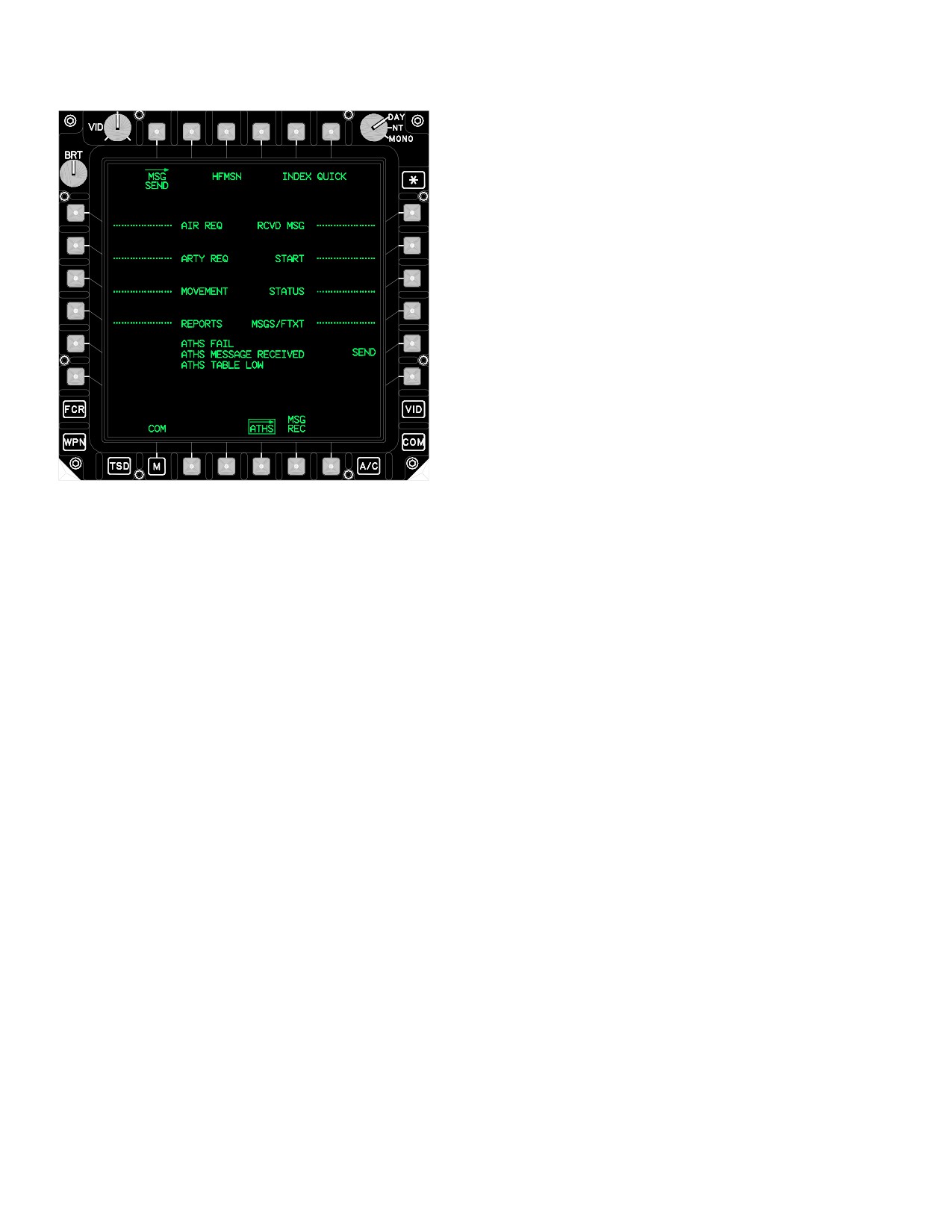
TM 1-1520-251-10
Mayday Message Summary Page.
Quick Menu Page.
c. START PAGES - DESCRIPTION.
NOTE
• ATHS - TACFIRE NETS are commonly
constructed using the AMPS during pre -
mission planning. When an AMPS is not
used, ATHS-TACFIRE NETS can be
constructed through the COM NET edit
pages.
• An ATHS-TACFIRE NET established
solely through the AH - 64D’s COM NET
edit pages will not support the Auto Ac-
knowledge selection.
• The zeroize line-key button does not
clear AFAPD messages or communica-
LBA5005
tion NETS.
The START pages (fig 3-60) are also available to manual-
Figure 3-59. ATHS - TACFIRE INDEX
ly initialize the IDM’s ATHS - TACFIRE functionality. The
pages maintain the files for communication, location, GO/
b. QUICK BUTTON FUNCTION. The QUICK but-
NO GO test, time, and authentication. Communication
ton appears on every ATHS - TACFIRE page. The QUICK
subscriber identifiers are entered as ORIGIN (ORIG),
function provides direct access to any one of the following
TEAM (TM), and BROADCAST (BC). Additionally, a ZER-
five operational ATHS - TACFIRE pages.
OIZE line - key button is provided in the START pages.
This ZEROIZE line - key button clears all data and table
Summary Page of Highest Priority Received Message.
entries from the IDM’s ATHS - TACFIRE component. The
START pages also include six message preset selections,
Airborne Mission Summary Page.
six movement preset selections, and a bulk data load
Artillery Mission Summary Page.
send/receive message capability.
Use or disclosure of this information is subject to the restriction(s) on the title page of this document.
3-50
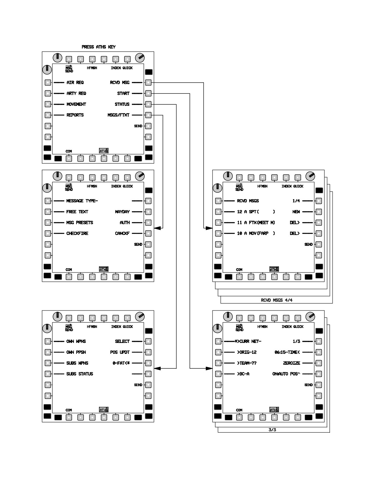
TM 1-1520-251-10
LBA3044A
Figure 3-60. ATHS TOP LEVEL (INDEX) MENU SELECTIONS
Use or disclosure of this information is subject to the restriction(s) on the title page of this document.
3-51
TM 1-1520-251-10
3.53.4 AIR REQUEST PAGES.
mission list is accomplished by pressing the paging (up-
per right) button on the MPD. Accessing a stored Air Mis-
sion Request Summary page is accomplished by pressing
a. Description. The Air Request (AIR REQ) list can
the left button adjacent to desired mission. Complete mis-
store up to eight fire mission requests. The three index
sion information will display. Initiating a new mission re-
pages display observer mission number, type of ord-
quest is accomplished by pressing a NEW key - button of
nance, firing element (LAUNCHER/subscriber) to which
an available mission number on the Air Request list, se-
request was sent, and mission status. This list is for origi-
lecting air mission type, entering the required parameters,
nating mission requests. Incoming new missions are
receiving the summary, and transmitting the data. Refer to
stored in the Received Message file. Stepping through the
figure 3-61 and 3-62.
Use or disclosure of this information is subject to the restriction(s) on the title page of this document.
3-52
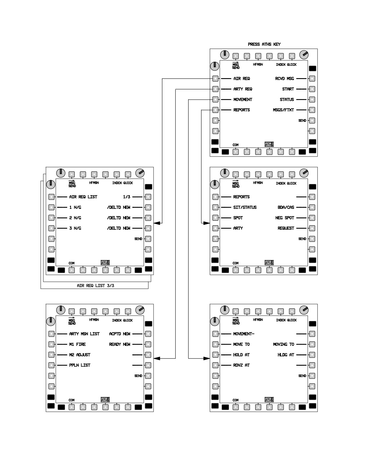
TM 1-1520-251-10
LBA3046A
Figure 3-61. AIR REQ, ARTY REQ, MOVEMENT, AND REPORTS MENU STRUCTURE
Use or disclosure of this information is subject to the restriction(s) on the title page of this document.
3-53
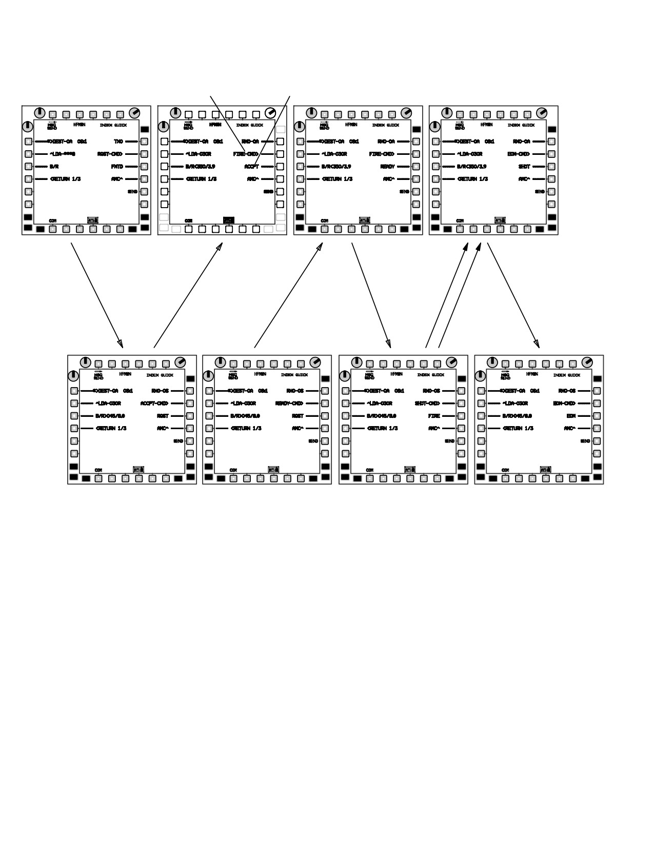
TM 1-1520-251-10
COMMAND
LAST RECEIVED
SELECT
MESSAGE
OBSERVER
93H
REQUEST
ACCEPT
READY
FIRE
1ST SHOT
2ND
EOM
SHOT
LAUNCHER
LBA3049A
Figure 3-62. SIMPLIFIED DIGITAL REMOTE HELLFIRE ATHS - TACFIRE AIR MISSION
(1) Types of air missions are as follows:
(b) OTHER ORDNANCE. Seven selections,
NO PREF, ATGM, GUN, HE, ILLUM, SMOKE, and
(a) HELLFIRE. The number of rounds to be
CHAFF.
fired is requested and guidance is by other than the
launching element.
(c) NO PREF.
Use or disclosure of this information is subject to the restriction(s) on the title page of this document.
3-54
TM 1-1520-251-10
(2) STORING / SENDING AIR MISSION FIRE
16. On Air Mission Summary page, SEND button -
REQUEST FOR ORDNANCE OTHER THAN REMOTE
Press.
HELLFIRE.
(3) DIGITAL REMOTE HELLFIRE LAUNCHER
1. Locate target - CAQ or KU enter as required.
(L) AND DESIGNATOR (D) MISSION EXECUTION.
NOTE
•
Remote HELLFIRE (REMOTE HLFR)
The last CAQ’d (T50 or etc.) will automati-
mission request. The paging required for
cally fill the target location data field. Subse-
a simplified request is depicted in fig
quent target CAQing targets will overwrite
3-62.
the target data.
•
Launcher AUTO SHOT should be set to
ON to enable automatic TOF messaging
2. COM page ATHS button - Press.
from the launcher to designator at trigger
pull.
3. INDEX button - Press as required to display
ATHS - TACFIRE index page.
• The launcher’s HFMSN should be boxed
to enable automatic CPG weapons mod-
4. AIR REQ line - key button - Press.
ing. Selecting the button will box and un-
box HFMSN.
5. Line (1 - 8) - Select mission number on which
mission is to be entered. NEW button - Press.
NOTE
When HFMSN is boxed T51 it will be auto-
6. MSN TYPE - Press appropriate button.
matically populated with the coordinate data
from the Hellfire message. T51 target data
7. As pages sequence, press appropriate button.
will be overwritten with the last CAQ’d target
when the operator toggles the HFSM but-
8. Air Mission Summary page - Review and
ton.
change parameters as required.
•
Set FAT on STATUS page to insure valid
TOF message. FAT is not integrated with
To execute a fire request, perform steps 9 and 10.
the 1553B bus.
9. On Air Mission Summary page, SEND button -
• The Mission Status will change from RE-
Press.
QUESTED to ACCEPTED, READY,
FIRE, and SHOT. At completion of mis-
10. ATHS button - Press and repeat steps 1 through
sion an END OF MISSION message
8 above for each net as required.
should be sent.
To recall and send a stored mission, perform steps
1.
(D) ATHS - Select.
11 through 14.
2.
(D) INDEX - Select as required.
11. INDEX button - Press as required to display
3.
(D) AIR REQ - Select.
ATHS - TACFIRE index page.
4.
(D) NEW (as desired) - Select next available air
12. AIR REQ line - key button - Press.
mission.
13. Desired mission (1 - 8) line number - Select.
NOTE
14. R1 button - Press to display Air Mission Sum-
There are three pages (3/3) of NEW AIR
mary page.
MSN’s available, select the next available
AIR MSN.
15.
*>DEST button - Enter SUB, TEAM or BC ad-
dress as desired through KU.
5.
(D) HELLFIRE - Select.
Use or disclosure of this information is subject to the restriction(s) on the title page of this document.
3-55
TM 1-1520-251-10
6.
(D) Locate target - CAQ or KU enter as re-
NOTE
quired.
• The Launcher must verify the LDA and
SEP angle. The LDA is the laser designa-
NOTE
tion angle and is the area in front of the
launching aircraft that the designating air-
The last target CAQ’d (T50 or ect.) will auto-
craft should avoid. This angle is +/ - 30
matically fill the target location data fill. Sub-
degrees of the launchers gun - target line
sequent target CAQing will overwrite the tar-
(software is set to flash at +/-
20 de-
get data.
grees).
• The Separation angle (SEP) is +/ - 60 de-
grees from the target back towards the
7. D) TARGET type - Select and set.
designator aircraft. This is the angle that
the designator should be inside to pre-
8.
(D) ACTIVITY - Select and set
clude a missile miss due to laser angle to
the missile. The SEP angle will flash
when the angle is greater than 60 de-
9.
(D) 1/3 - Select and advance to page 2/3.
grees.
• The launcher must verify that the target is
10.
(D) MST (missile separation time) TRAJ, Code/
within range based upon the environ-
quantity - Set/verify.
mental conditions. The range is set to
flash at ranges greater than 4.0KM. The
bearing to the target is relative to the
NOTE
launcher in this case and the > indicates
the closest direction to turn to the target.
The LDA/SEP L2 on 2/3 should be ignored.
Data will not accurately display on page 2/3
• Range and bearing are displayed appro-
until both the DEST subscriber 3/3 has been
priately for the aircraft location (launcher
entered and valid subscriber data is avai-
and designator).
lable. Valid subscriber data is automatically
provided if a previous situation report was
17.
(L) CMD line - Verify ACCPT is displayed.
received or an ATHS-TACFIRE position
query was performed. Page 3/3 also dis-
18.
(L) SEND - Select and note send/receive advi-
plays the LDA/SEP data bloc.
sory status R1.
19.
(L) - CMD line - Verify that READY is now dis-
11.
(D) Select 2/3 - Advance to page 3/3 and verify
played.
Range/Bearing to TGT.
20.
(L) SEND - Select and not send/receive adviso-
ry status R1.
12.
(D) >DEST - ?? - Select and enter subscriber ID.
21.
(D) - CMD line - Verify that FIRE is now dis-
played.
13.
(D) SEND - Select and note send/receive advi-
sory status R1.
22.
(L) SEND - Select and note send/receive advi-
sory status R1.
14.
(L) ATHS MSG - Receive. Select INDEX page
23.
(L) Missile in constraints, FIRE missile, and
and RCVD MSG buttons.
auto - send or manual send SHOT CMD.
15.
(L) Message buffer address L 2, L3, or L4 - Se-
24.
(D) - Monitor TOF, LASE target at delay time.
lect to open AIR REQ Message.
25.
(L) - FIRE second missile at MST, if required.
16.
(L) LDA/SEP, B/R, Mode, Code, & Qty - Verify
26.
(D) - Monitor TOF, LASE target for second mis-
data.
sile.
Use or disclosure of this information is subject to the restriction(s) on the title page of this document.
3-56
TM 1-1520-251-10
27.
(D) - CMD line - Set to EOM.
b. Types of artillery mission requests are as fol-
lows:
28.
(D) - SEND - Select and note send/receive ad-
(1) NEW TGT. Observer defines target type and
visory status R1.
strength.
(2) Known Point (KNPT TGT). The observer de-
NOTE
fines a point which is a location previously identified and
numbered, known both to the requestor and to the artillery
The receipt of the EOM will automatically
FDC. The requestor then provides target type and
mode the CPG’s weapon systems back to
strength.
their previous settings.
(3) QUICK. Requestor enters only a known point.
All other data is known by the artillery FDC.
3.53.5 ARTILLERY REQUEST PAGES.
(4) Preplanned (REQ PPLN). Observer provides
type of fire request (either Final Protective Fire (FPF) or
a. Description. The mission data contained in the
Copperhead (CPHD) guided munitions). Only one FPF
IDM is formatted to be consistent with the TACFIRE Artil-
can be preplanned at a time; however, both preplanned
lery Fire Direction Center (FDC) system and associated
missions can be Copperhead. The requestor then pro-
forward observer digital message devices (DMD). Artillery
vides target position and known point number.
mission command selection is initially entered on the
(5) Copperhead (CPHD). Target position is de-
ARTY MISSION SUMMARY page automatically as REQ.
fined as NEW or Known Point and point number is pro-
Upon receipt of the TACFIRE FDC message - to - observer
vided to the firing element
(MTO), the mission command will automatically change to
FIRE. A READY command will be displayed if the Battery
c. ARTILLERY FIRE REQUESTS.
Computer System (BCS) is online with TACFIRE. Target
position (range and bearing from the helicopter) is auto-
There are three types of artillery fire requests - pre-
matically calculated. By pressing the TGT PSN (target
planned, new, and Copperhead.
position) button, the operator can manually enter the UTM
grid, range, bearing, and altitude of the target on sub-
d. PREPLANNED FIRE REQUESTS.
pages if required. The Artillery Request List stores two ac-
tive artillery missions and two preplanned mission re-
To insert a preplanned fire request, proceed as follows:
quests on the Preplanned Mission List subpage.
Accessing either active mission is accomplished by press-
1. COM page ATHS button - Press .
ing the M1 or M2 button on the ARTY REQ list page. To
review a preplanned mission, pressing the PPLN LIST
2. INDEX button - Press, as required, to display
button on the Preplanned Mission List page will cause the
ATHS - TACFIRE INDEX page.
Preplanned Mission Summary page to display.
3. ARTY REQ line - key button - Press.
NOTE
4. NEW line - key button - Press (On line opposite
mission to be replaced).
In order to store a preplanned mission, a
preplan request must be executed and
5. REQ PPLN button - Press.
stored as a standard artillery preplan re-
6. Mission type - Select either FPF or CPHD as
quest. Then the mission must be inserted
desired.
into preplan list.
NOTE
Initiating a new artillery mission request is accomplished
If KNPT TGT is selected, entry of two - digit
by pressing the NEW line - key button of an available mis-
KNPT number is required.
sion number, selecting artillery mission type, following
prompts through the subpages, reviewing summary page,
7. KNPT TGT or NEW TGT - Select as appropri-
and transmitting data.
ate.
Use or disclosure of this information is subject to the restriction(s) on the title page of this document.
3-57
TM 1-1520-251-10
8. ARTY mission summary page will appear -
7. Review mission on summary page and make
Press SEND. Wait for preplanned MTO then
changes as required.
continue.
8.
*>DEST button - Enter SUB, TEAM or BC ad-
9. INDEX button - Press to return to ATHS - TAC-
dress as desired through KU.
FIRE index page.
9. SEND button - Press.
10. ARTY REQ line - key button - Press.
f. COPPERHEAD FIRE MISSION - ACTIVE AND
PREPLANNED.
11. PPLN LIST button - Press.
To accomplish a Copperhead fire mission, proceed as fol-
12. P1 or P2 - Press NEW as desired.
lows:
13. L2 - Press on preplan insertion pages.
1. Locate target - CAQ or KU enter as required.
14. Repeat steps 1. through 11. to insert a second
NOTE
preplanned mission.
The last target CAQ’d (T50 or ect.) will auto-
matically fill the target location data fill. Sub-
NOTE
sequent target CAQing will overwrite the tar-
If the PPLN mission is requested as M1, it
get data.
can only be stored as P1.
2. COM page ATHS button - Press as required.
e. NEW ARTILLERY FIRE MISSION REQUEST.
3. INDEX button - Press, as required, to display
To initiate a new fire mission, proceed as follows:
ATHS - TACFIRE INDEX page.
1. Locate target - CAQ or KU enter as required.
4. ARTY REQ line - key button - Press.
5. To accomplish in active mission, M1 or M2 but-
NOTE
ton - Press as desired.
The last target CAQ’d (T50 or ect.) will auto-
matically fill the target location data fill. Sub-
6. CPHD - Press.
sequent target CAQing will overwrite the tar-
get data.
NOTE
If KNPT TGT is selected, entry of two - digit
2. COM page ATHS button - Press as required.
KNPT number is required.
3. INDEX button - Press, as required, to display
7. NEW TGT or KNPT TGT - Select as appropri-
ATHS - TACFIRE INDEX page.
ate.
4. ARTY REQ line - key button - Press.
8. ARTY mission summary page will appear - Re-
view ARTY mission summary page and change
5. NEW button opposite mission (M1 or M2) to be
as required.
replaced - Press.
9.
*>DEST button - Enter SUB, TEAM or BC ad-
6. Mission type - Press applicable button and en-
dress as desired through KU.
ter required parameters on subsequent pages
until all data is inserted.
10. SEND button - Press.
Use or disclosure of this information is subject to the restriction(s) on the title page of this document.
3-58
TM 1-1520-251-10
3.53.6
MOVEMENT COMMAND COMMUNICA-
a. SITUATION/STATUS (SIT/ STATUS). Report
TIONS. The MOVEMENT pages allow position instruc-
Transmission. To transmit observers situation and/or sta-
tions to be transmitted without voice communication. The
tus, proceed as follows:
IDM operator can issue directions to specific or all team
members to MOVE TO, HOLD AT, rendezvous (RDZV) at;
NOTE
or inform team members MOVlNG TO or HLDG AT a loca-
Attached to the situation report, the AH - 64D
tion. The locations can be preset to allow QUICK commu-
will automatically include the ownship’s fuel,
nication. In addition, the MOVEMENT pages allow auto-
AMMO (30 mm), rocket, and missile
matic transmission of current position through MY
(FARM) quantities. No operator input is re-
POSITION button and free text communication through
quired, all FARM data is taken off the 1553B
the OTHER button.
bus.
a. MOVEMENT COMMAND TRANSMISSION.
1. COM page ATHS button - Press as required.
Transmit movement commands as follows:
2. INDEX button - Press, as required, to display
ATHS - TACFIRE INDEX page.
1. COM page ATHS button - Press as required.
3. REPORTS line - key button - Press.
2. INDEX button - Press, as required, to display
4. Activity to report - Press the desired activity but-
ATHS - TACFIRE INDEX page.
ton:
• 1) HOLDING.
3. MOVEMENT line - key button - Press.
•
2) CONT MSN.
4. Appropriate movement type button - Press.
• 3) OBS TGT.
• 4) ENGAGING.
5. Appropriate destination select button - Press.
5. Report summary page - Review and change as
NOTE
required.
Pressing the OTHER button will display
NOTE
freetext message entry page where a manu-
The situation report location data fill is the
al entry can be made using KU.
ownship’s location. Location is automatical-
ly filled from data taken off the 1153B bus.
6. Mission summary page - Review and change as
required.
6.
*>DEST button - Enter SUB, TEAM or BC ad-
dress as desired through KU.
7.
*>DEST button - Enter SUB, TEAM or BC ad-
dress as desired through KU.
7. SEND button - Press.
b. SPOT REPORT TRANSMISSION.
8. SEND button - Press.
To transmit a spot report, proceed as follows (fig. 3-61):
3.53.7 REPORT COMMUNICATIONS. The REPORTS
pages (fig. 3-60) allow the observer to provide various in-
1. Locate target - CAQ, store or receive as re-
formation to team and net members such as: Situation/
quired.
status (SIT/STATUS) which reports the observers own sit-
uation, SPOT which reports target activity, ATI or provide
NOTE
intelligence reports to artillery units, BDA to report battle
damage assessments, CAS to report casualty assess-
The last target CAQ’d (T50 or ect.) will auto-
ments, NEG SPOT, and REQUEST to request a report
matically fill the target location data fill. Only
from another subscriber.
one location data fill is available.
Use or disclosure of this information is subject to the restriction(s) on the title page of this document.
3-59
TM 1-1520-251-10
2. COM page ATHS button - Press as required.
5. BDA summary page - Press appropriate button
and manually enter information using KU.
3. INDEX button - Press, as required, to display
ATHS - TACFIRE INDEX page.
NOTE
The last target CAQ’d (T50 or ect.) will auto-
4. REPORTS line - key button - Press.
matically fill the target location data fill.
5. SPOT button - Press.
6.
*>DEST button - Enter SUB, TEAM or BC ad-
dress as desired through KU.
NOTE
7. SEND button - Press.
Three different target types may be entered
for each SPOT report.
d. CASUALTY (CAS) REPORT TRANSMISSION.
6.
TARGET type - Press appropriate button.
To provide casualty reports, proceed as follows:
7.
Target strength (STR) - Press appropriate but-
1. COM page ATHS button - Press as required.
ton.
2. INDEX button - Press, as required, to display
8.
R1 button - Press.
ATHS - TACFIRE INDEX page.
9.
ALT button - Press as desired.
3. REPORT line - key button - Press.
10.
Target (TGT) ACTIVITY - Select as desired. If
4. BDA/CAS button - Press.
MOVING is selected, proceed to step 10. If STA-
TIONARY is selected, proceed to step 11.
5. CAS summary page - Press appropriate button
and manually enter information using KU.
11.
Target direction - Press appropriate button.
NOTE
12.
R1 button - Press.
The last target CAQ’d (T50 or ect.) will auto-
matically fill the target location data fill.
13.
Mission summary page - Review and change as
required.
6.
*>DEST button - Enter SUB, TEAM or BC ad-
dress as desired through KU.
14.
*>DEST button - Enter SUB, TEAM or BC ad-
dress as desired through KU.
7. SEND button - Press.
e. ARTILLERY INTELLIGENCE REPORT (ATI)
15.
SEND button - Press.
TRANSMISSIONS.
c. BATTLE DAMAGE ASSESSMENT (BDA) RE-
To transmit an artillery intelligence (ATI) report, proceed
PORT TRANSMISSION.
as follows:
To provide battle damage assessments, proceed as fol-
1. COM page ATHS button - Press as required.
lows:
2. INDEX button - Press, as required, to display
1. COM page ATHS button - Press as required.
ATHS - TACFIRE INDEX page.
2. INDEX button - Press, as required, to display
3. REPORTS line - key button - Press.
ATHS - TACFIRE INDEX page.
4. ATI button - Press.
3. REPORTS line - key button - Press.
5. REL - Scroll through reliability option until de-
4. BDA/CAS button - Press.
sired option is displayed.
Use or disclosure of this information is subject to the restriction(s) on the title page of this document.
3-60
TM 1-1520-251-10
6. Target type - Press appropriate button.
3.53.8 STATUS PAGES. The STATUS pages (fig. 3-60)
provide a means of maintaining and reviewing the last
7. Target strength - Press appropriate button.
position, fuel, ammunition, rocket, and missile (FARM)
status of subscribers. STATUS pages are automatically
filled each time a subscribers situation report is received.
8. R1 button - Press.
The status pages also maintain the ownship’s dynamic
status. The weapons format will depend on whether the
9. RAD/LGTH, WIDTH, and ATTITUDE buttons -
subscriber is defined in an AIR NET or a TACFIRE NET.
Press as appropriate.
The subscriber pages will be automatically updated upon
receipt of a situation/status report.
10. R1 button - Press.
NOTE
11. ATl summary page - Review and change as re-
quired.
All ownship FARM data is automatically tak-
en from the 1553B bus. There is no need to
NOTE
input or edit ownship data.
The last target CAQ’d (T50 or ect.) will auto-
a. OWN STATUS.
matically fill the target location data fill.
To review own status, proceed as follows:
12.
*>DEST button - Enter SUB, TEAM or BC ad-
dress as desired through KU.
1. COM page ATHS button - Press as required.
13. SEND button - Press.
2. INDEX button - Press, as required, to display
ATHS - TACFIRE INDEX page.
f. REPORT REQUESTING FROM ANOTHER SUB-
SCRIBER.
3. STATUS line - key button - Press.
To request a report from another subscriber, proceed as
4. OWN WPNS or OWN PPSN button - Press as
follows:
desired.
5. For OWN WPNS entry, laser designator code -
1.
COM page ATHS button - Press as required.
Enter using KU and press paging select button
(1/1) to return to status index page.
2.
INDEX button - Press, as required, to display
ATHS - TACFIRE INDEX page.
b.
OWN PPSN ENTRY.
3.
REPORTS line - key button - Press.
1. Present position is continuously updated from
the 1553B bus. If a contingency warrants, PPSN
4.
REQUEST button - Press.
may be manually edited. To change, enter coor-
dinates using KU and UTM button - Press.
5.
On report request select page - Press appropri-
ate button to designate type of report desired.
2. ALT is entered continuously from the 1553B
bus. If a contingency warrants, ALT may be
6.
DEST - button on summary page - Press and
manually edited. ALT button - Press. Enter alti-
enter subscriber identifier from which report is
tude in meters or enter N/G.
desired using KU.
3. FUEL is continuously updated from the 1553B
7.
Request report summary page - Review and
bus. If a contingency warrants, FUEL may be
change as required.
manually edited. FUEL button - Press and en-
ter.
8.
“>DEST button - Enter SUB, TEAM or BC ad-
dress as desired through KU.
4. Paging select (1/1) - Press to return to status in-
dex page (fig. 3-60). To obtain the status of a
9.
SEND button - Press to transmit request.
single subscriber, proceed as follows:
Use or disclosure of this information is subject to the restriction(s) on the title page of this document.
3-61
TM 1-1520-251-10
c. WEAPONS STATUS - ALL SUBSCRIBERS.
e. WEAPONS/PRESENT POSITION STATUS -
SINGLE SUBSCRIBER.
To obtain subscriber weapons status, proceed as follows:
1. COM page ATHS button - Press as required.
1. COM page ATHS button - Press as required.
2. INDEX button - Press, as required, to display
2. INDEX button - Press, as required, to display
ATHS - TACFIRE INDEX page.
ATHS - TACFIRE INDEX page.
3. STATUS line - key button - Press.
3. STATUS button - Press.
4. SELECT button - Press.
4. SUBS WPNS button - Press. Review weapons
status of net subscribers as IDM automatically
5. SUB - button - Press. Enter desired subscriber
sequences from the first subscriber in NET 1 to
identifier using KU. Present position page will
the last subscriber in NET 8.
display.
5. Paging button - Press to return to status index
6. Paging button - Press to review weapons sta-
page.
tus.
d. PRESENT POSITION STATUS - ALL SUB-
7. Weapons status paging button - Press to return
SCRIBERS.
to status index page.
To obtain present position information on all net subscrib-
f.
SUBSCRIBER POSITION STATUS.
ers, proceed as follows:
1.
COM page ATHS button - Press as required.
1. COM page ATHS button - Press as required.
2.
INDEX button - Press, as required, to display
2. INDEX button - Press, as required, to display
ATHS - TACFIRE INDEX page.
ATHS - TACFIRE INDEX page.
3.
STATUS line - key button - Press.
3. STATUS line - key button - Press.
4.
POS UPDT button - Press.
4. SUBS PPSN button - Press.
5.
SUBS POSITION button - Press and review.
NOTE
6.
Repeat steps 1 through 3.
• Subscriber status will begin with the first
subscriber in NET 1 and display, in order,
7.
SUBS NET button - Select appropriate NET.
through the last subscriber in NET 8 as
paging button is pressed.
8.
Repeat steps 4 and 5 as desired.
• UTM button can be alternately pressed to
display UTM grid coordinates or range
9.
SUMMARY page - Review and select destina-
and bearing of subscriber status being
tion.
displayed.
10.
*>DEST button - Enter SUB, TEAM or BC ad-
5. If desired, return to status index page by press-
dress as desired through KU.
ing paging button once more after last subscrib-
er status is displayed.
11.
SEND button - Press.
Use or disclosure of this information is subject to the restriction(s) on the title page of this document.
3-62
TM 1-1520-251-10
3.53.9
FREE TEXT/PRESET PAGES. The FREE
7. SEND button - Press to transmit message.
TEXT/PRESET message pages (fig. 3-60) allow the ob-
server to compose and transmit any message up to 36
b. PRESET MESSAGE TRANSMISSION.
characters (two lines) at any time. Also, these pages allow
messages to be composed and stored for subsequent re-
To transmit any of up to six preset messages entered dur-
call and transmission at the appropriate time. The top
ing IDM initialization, proceed as follows:
message page includes a MAYDAY for QUICK MAYDAY
broadcasts, a CHECKFIRE message for a QUICK cease
1. COM page ATHS button - Press as required.
fire broadcast, an authentication synchronization mes-
sage to align the FDC codes to the IDM codes, and cancel
2. INDEX button - Press, as required, to display
checkfire message. The free text and preset messages
ATHS - TACFIRE INDEX page.
contain the same information. The free text/preset mes-
sages are automatically addressed to the team subscriber
3. MSGS/FTXT line - key button - Press.
identifier. the MAYDAY message is addressed to the
broadcast subscriber identifier, and contains the MAYDAY
4. MSG PRESETS button - Press.
message and own present position. The Authentication
Synchronization (AUTH) message is addressed to the
5. Select message to be transmitted by pressing
broadcast subscriber identified in the start pages with
button adjacent to appropriate message num-
whom the automatic authentication is to occur (normally
ber.
TACFIRE). If, after transmission, a NAK is returned, the
tables are out of synchronization. TACFIRE will still get
6. DEST - button - Press and enter subscriber
the message and change tables to match the observers.
identifier.
TACFIRE will call back once synchronization has been ac-
complished.
7. SEND button - Press.
a. FREE TEXT MESSAGE COMPOSITION AND
8. To return to ATHS - TACFIRE index page, IN-
TRANSMISSION.
DEX button - Press.
To compose and transmit a free text message, proceed as
c. CHECKFIRE MESSAGE TRANSMISSION.
follows:
To broadcast a cease fire message to all subscribers, pro-
1. COM page ATHS button - Press as required.
ceed as follows:
2. INDEX button - Press, as required, to display
1. COM page ATHS button - Press as required.
ATHS - TACFIRE INDEX page.
2. INDEX button - Press, as required, to display
3. MSGS/FTXT line - key button - Press.
ATHS - TACFIRE INDEX page.
4. DEST button - Enter subscriber identifier using
3. MSGS/FTXT line - key button - Press.
KU.
4. CHECKFIRE button - Press.
NOTE
When FREE TEXT - TEST is used for com-
5. Broadcast identifier is automatically inserted to
munication check, data is not required.
change: DEST - button - Press and enter identi-
fier. using KU.
5. FREE TEXT button - Press to scroll between
TEST and DATA as required.
6. SEND button - Press.
6. Message - Enter any message up to 36 charac-
7. To return to ATHS - TACFIRE index page, IN-
ters long using KU.
DEX button- Press.
Use or disclosure of this information is subject to the restriction(s) on the title page of this document.
3-63
TM 1-1520-251-10
d. MAYDAY MESSAGE TRANSMISSION.
4. AUTH button - Press.
To broadcast a MAYDAY message, proceed as follows:
5. DEST - button - Press. Enter identifier of sub-
scriber with which automatic authentication is
1. COM page ATHS button - Press as required.
desired.
6. When desired, SEND button - Press.
2. INDEX button - Press, as required, to display
ATHS - TACFIRE INDEX page.
NOTE
3. MSGS/FTXT line - key button - Press.
• If authentication tables between sender
and receiver are not synchronized, a
4. MAYDAY button - Press.
NAK will be returned. Sender should not
retransmit.
5. Present position is automatically filled from the
• Receiver should change table positions
1153B bus. To change present position in UTM
and transmit to original sender with tables
grid, POSITION button - Press. Enter UTM us-
synchronized.
ing KU.
f. CANCEL CHECKFIRE MESSAGE TRANSMlS-
6. Broadcast identifier is automatically inserted to
SION.
change: DEST - button - Press and enter identi-
fier.
To broadcast a cancel checkfire message, proceed as fol-
lows:
7. SEND button - Press.
1. COM page ATHS button - Press as required.
8. To return to ATHS - TACFIRE index page, IN-
DEX button - Press.
2. INDEX button - Press, as required, to display
ATHS - TACFIRE INDEX page.
e. A U T H E N T I C A T I O N SYNCHRONIZATION
TRANSMISSION.
3. MSGS/FTXT line - key button - Press.
To broadcast an Authentication Synchronization transmis-
4. CANCKF button - Press.
sion, proceed as follows:
5. DEST button - Press. Enter identifier of sub-
1. COM page ATHS button - Press as required.
scriber as desired.
2. INDEX button - Press, as required, to display
6. SEND button - Press.
ATHS - TACFIRE INDEX page.
7. To return to ATHS - TACFIRE index page, IN-
3. MSGS/FTXT line - key button - Press.
DEX button - Press.
Use or disclosure of this information is subject to the restriction(s) on the title page of this document.
3-64