HELICOPTER, ATTACK, AH-64D LONGBOW APACHE. TECHNICAL MANUAL (2002) - page 2
TM 1-1520-251-10
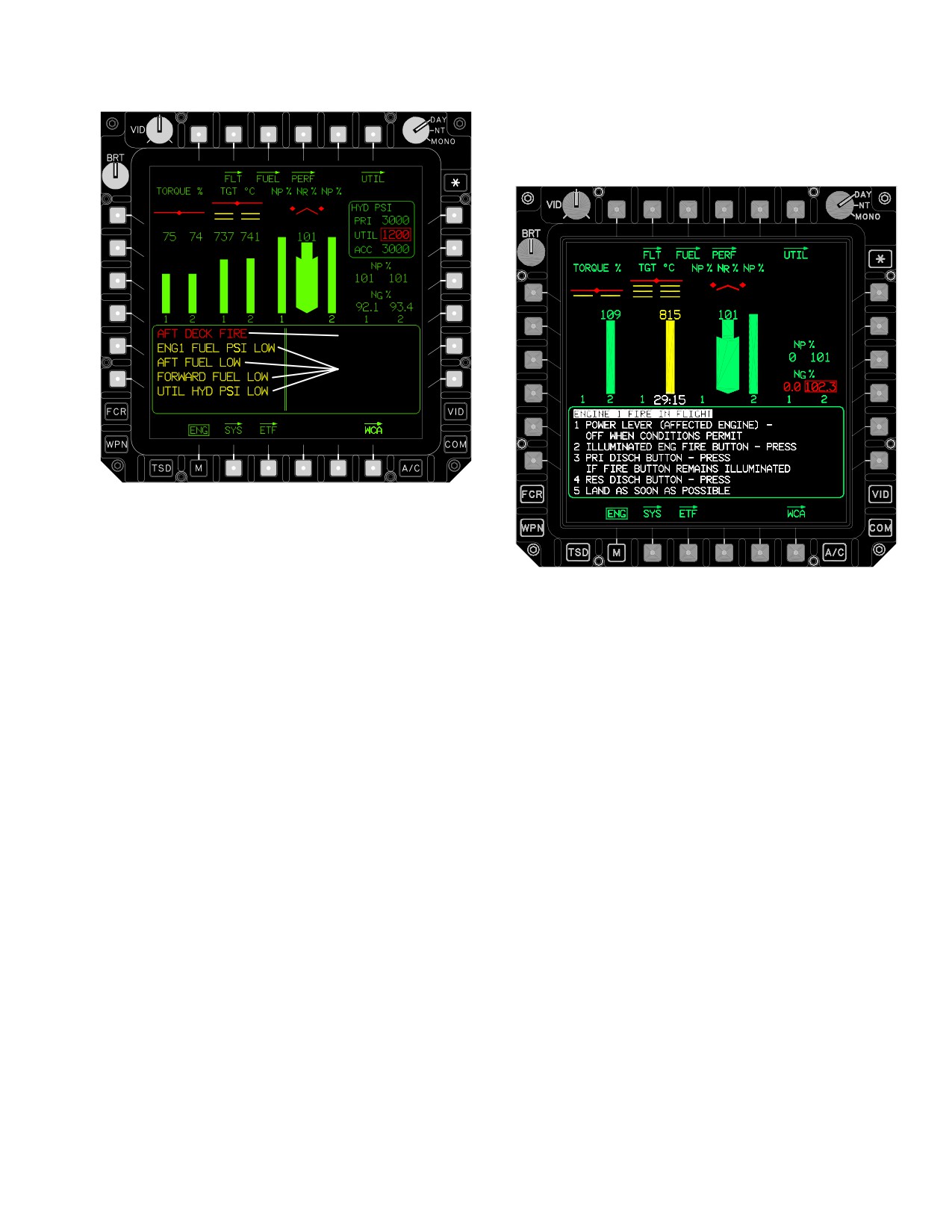
This text, displayed in WHITE, is provided to allow the
crew to rapidly verify procedures once immediate correc-
tive action has been taken.
WARNING
CAUTIONS
LBA−3003
Figure 2-46. In - flight Format - Active Warnings
LBA5191
and Cautions
Figure 2-47. ENG Instruments Page Emergency
Format
NOTE
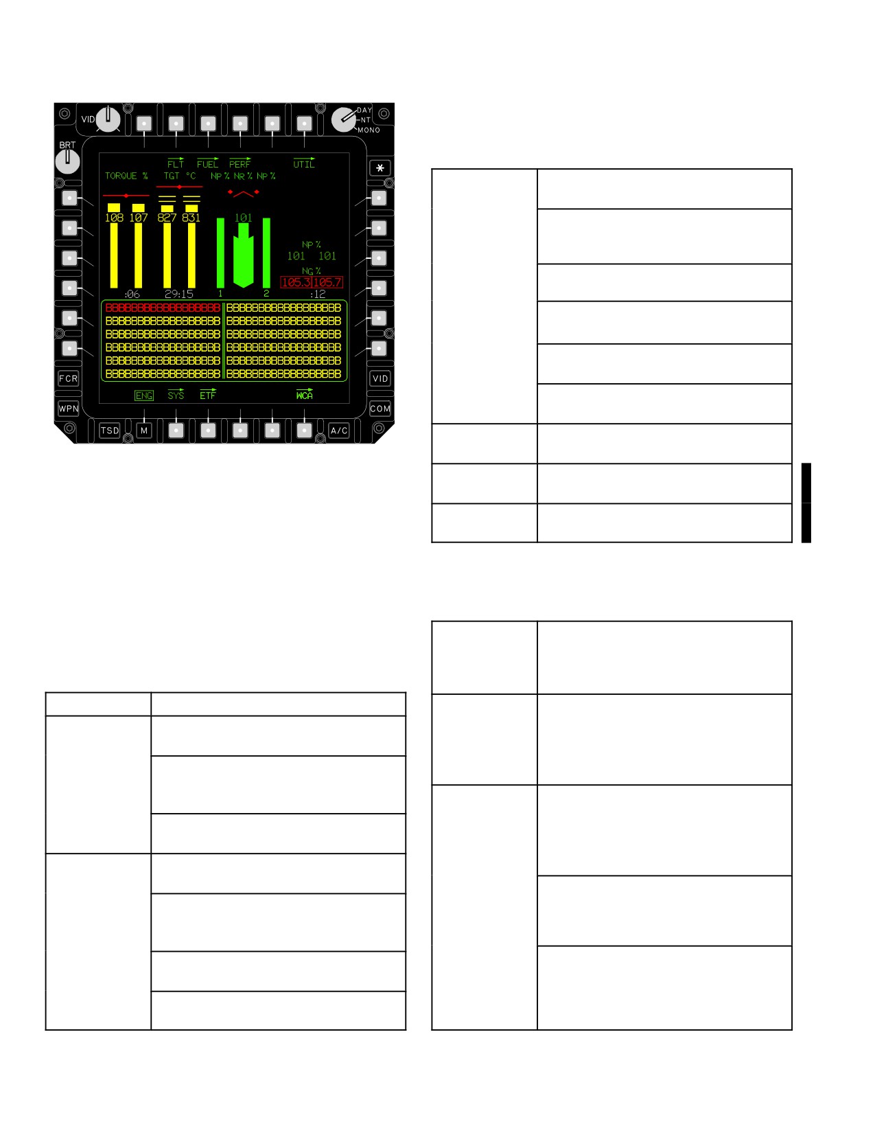
2.48.4 Count-Down Timers. Count-down-timers are
displayed in WHITE on the MPD ENG Page (fig 2-48) and
Emergency procedures will be displayed on
decrement based upon the parameters listed in Table 2-4.
the ENG page emergency format only when
When a timer has decremented completely, it displays 0:0
a DTC with procedures data is installed and
until reset. In addition Engine TGT values are displayed
loaded.
on the FLT Page and the HMD based upon the parame-
ters in Table 2-5.
2.48.3
ENG Page Emergency Format.. The ENG
NOTE
page emergency format (fig 2-47) is automatically dis-
played in response to all aircraft warnings. The upper half
During multiple timer operations, the highest
of the ENG page emergency format displays the same in-
timer number (1 - 4) value will be displayed.
dications as the ground and in-flight formats (Table 2-2).
Earlier timers will continue to run. As power
The lower half of the page will display a window containing
is reduced, each preceding timer value will
the immediate action steps associated with the active
be displayed, and each timer will be reset,
warning condition.
automatically, in order.
Use or disclosure of this information is subject to the restriction(s) on the title page of this document.
2-41
TM 1-1520-251-10
Table 2-4 Engine Page Timers (cont)
TGT ( - 701C)
Dual Engine: u
810 °C, timer
decrements from 30 minutes. (timer1).
Either engine: u
870 °C, timer decre-
ments from 10 minutes
(timer 2).
Single Engine: >810 °C, timer decre-
ments from 30 minutes (timer 1)
u
870 °C, timer decrements from
10 minutes (timer 2).
<878 °C timer decrements from 2
minutes and 30 seconds (timer 3).
<896 °C timer decrements from 12
seconds (timer 4).
NG
Either engine NG u
102.2%, timer
decrements from 12 seconds.
LBA3005
NP 1
Engine 1 NP > 105%, timer
decrements from 12 seconds.
NP 2
Engine 2 NP > 105%, timer
decrements from 12 seconds.
Figure
2-48.
Engine Instrument Timers
Table
2-5. MPD FLT Page and HMD TGT
TGT ( - 701)
Dual engine: u
807 °C, timer
Table
2-4. Engine Page Timers
decrements from 30 minutes. TGT
value is displayed on HMD and FLT
page during the final 2 minutes.
PARAMETER
CONDITIONS
Single engine: u
864°C, timer
decrements from 2 minutes and 30
TORQUE
Dual Engine: u
100%, timer
seconds. TGT value is displayed on
decrements from 6 seconds.
HMD and FLT page the entire 2
Single Engine: u
110% (contingency),
minutes and 30 seconds (timer 2).
timer decrements from 2 minutes and
TGT ( - 701C)
Dual engine: u
810 °C, timer
30 seconds (timer 1).
decrements from 30 minutes. TGT
u
122% timer decrements from
value is displayed on HMD and FLT
6 seconds (timer 2).
page during the final 2 minutes (timer
TGT ( - 701)
Dual Engine:u
807 °C, timer
1).
decrements from 30 minutes.
u
870 °C, timer decrements from 10
Single Engine:u
807 °C, timer
minutes. TGT value is displayed on
decrements from 30 minutes
HMD and FLT page during the final 2
minutes (timer 2).
(timer 1).
Single Engine: >878 °C, timer decre-
>864 °C, timer decrements from
2
ments from 2 minutes and 30 sec-
minutes and 30 seconds (timer 2).
onds. TGT value is displayed on HMD
u
919 °C, timer decrements from
and FLT page the entire 2 minutes
12 seconds (timer 3).
and 30 seconds (timer 3).
Use or disclosure of this information is subject to the restriction(s) on the title page of this document.
2-42
Change 4
TM 1-1520-251-10
Section IV. FUEL SUPPLY SYSTEM
2.49 FUEL SUPPLY SYSTEM
into the outboard auxiliary tank forcing the fuel from the
outboard auxiliary tank to the inboard auxiliary tank and
NOTE
then to the internal fuel cells. When an internal auxiliary
fuel cell is installed, an electric pump is used to transfer
Fuel grades, specifications, and servicing
fuel from the internal auxiliary fuel cell directly into the for-
instructions are described in Servicing,
ward and aft fuel cells simultaneously. Both auxiliary fuel
Parking, and Mooring, Section XV.
subsystems are selected on/off via the MPD and man-
aged through fuel system priorities.
The fuel system (fig 2-49) provides fuel and fuel manage-
ment provisions to operate both engines and the APU.
2.53 FUEL CROSSFEED SUBSYSTEM
Fuel is stored in two crash resistant, self sealing fuel cells;
one forward and one aft of the ammunition bay. Fuel may
WARNING
be transferred from either cell to the other. Fuel levelling
can be accomplished manually or automatically. The sys-
tem is also equipped to selectively crossfeed fuel to en-
The CROSSFEED button shall be set to
gines from either the forward or aft fuel cells. The aircraft
NORM position at all times while in flight,
has provisions for carrying external fuel tanks on the wing
unless executing emergency procedures
pylon attach points. There is also a provision for an inter-
for engine 1 fuel PSI and engine 2 fuel
nal auxiliary fuel cell carried in the ammunition bay.
PSI. A malfunctioning crossfeed valve
could result in a single engine flameout.
2.50 FUEL TANKS
The crossfeed subsystem allows both engines to draw
Two internal fuel cells provide the main storage for the air-
fuel from either internal fuel cell. There are two crossfeed
craft fuel supply. The forward fuel cell holds 156 gal.; the
valves, one for each engine. The valves are three-way,
aft fuel cell holds 220 gal.
four-position valves. The crossfeed modes are crewmem-
ber selectable functions via the MPD. Crossfeed mode
2.51 EXTENDED RANGE KIT
selections are described in paragraph 2.60.4. The AFT
crossfeed is automatically activated for the engine being
Up to four auxiliary tanks can be mounted on the four wing
started by the system processor during engine start. After
pylons for extended range operations. Each auxiliary tank
start, the crossfeed is automatically reset to NORM.
holds up to 230 usable gal. The auxiliary tanks can be jet-
2.54 FUEL QUANTITY SUBSYSTEM
tisoned in the same manner as any other externally
mounted stores.
The fuel quantity subsystem measures remaining fuel and
detects low levels in the forward and aft fuel cells. The fuel
2.51A INTERNAL AUXILIARY FUEL SYSTEM (IAFS)
quantity is displayed in lb for each cell and for the total in-
ternal fuel remaining. A forward fuel low caution message
An internal auxiliary fuel cell can be installed in the am-
is displayed when the forward cell quantity drops below
munition bay for extended range operations. The internal
240 lb or when the low level switch in the fuel cell is acti-
auxiliary fuel system holds a 129, or a 98, usable gal. cell.
vated. The low level switch will be activated at a lower fuel
The fuel cell may be equipped with a fuel probe that mea-
quantity of 175 ±20 lb. An aft fuel low caution message is
sures the fuel quantity.
displayed when the aft cell quantity drops below 260 lb or
2.52 FUEL TRANSFER SUBSYSTEM
when the low level switch in the fuel cell is activated. The
low level switch will be activated at a fuel quantity of 240
The fuel transfer subsystem allows for the transfer of fuel
±20 lb. When an auxiliary tank is empty an advisory is an-
between the internal fuel cells and from both the external
nunciated.
tanks and the internal auxiliary fuel cell to the internal fuel
2.55 FUEL BOOST SUBSYSTEM
cells. The internal fuel transfer pump is a pneumatically
driven pump that allows the transfer of fuel between the
The fuel boost pump provides pressurized fuel during en-
forward and aft fuel cells, and from external fuel tanks to
gine start and is used to increase fuel pressure when
the internal forward and aft cells. The internal transfer
manually selected ON. The pneumatically driven boost
mode provides manual and automatic selections via the
pump pressurizes the fuel line out of the aft cell. Under
MPD. When external fuel tanks are mounted on both the
normal operation, fuel is drawn out of the fuel cells by the
inboard and outboard pylons, pressurized air is routed
main engine fuel pumps.
Use or disclosure of this information is subject to the restriction(s) on the title page of this document.
Change 2
2-43
TM 1-1520-251-10
BREAKAWAY VALVE
ENG
TO ENG 2
CELL
ÔÔÔÔÔ
RIGHT SIDE
BOOST PUMP
PRESSURE SWITCH
ENÔÔ
X FEED
ÔÔ
Ô
APU
APU FUEL
ENG
RIGHT CROSSFEED
FUEL BOOST
SHUTOFF
SHUTOFF VALVE
PUMP
N2 CHECK
VALVE
VALVE
TO APU
XFEED
FLOW
REGULATED
AIR FROM
29 +
PRESS
PAS SYSTEM
2 PSI
AIR IN
BOOST
19+ 3 PSI
INLET
PUMP
COOLING
SHUTOFF
AIR
OUTLET
VALVE
AUX
FUEL TANK
AIR SHUTOFF
GRAVITY
BREAKAWAY
VALVE
FILLER
VALVES
PORT (CAP)
FUEL
CLOSE
AIR
FUEL
IN
XFER PUMP
AIR IN
XFER
AIR VALVE
Ô
OPEN
DRAIN
ÏÏÏÏÏÏÏÏÏÔ
Ï
FUEL
BREAKAWAY VALVE
PILOT
FUEL
VALV
DRAIN
Ï
ÔÔAIR VENT
E
Ï
TUBE
FUEL/DEFUEL
PRESS
CHECK VALVE
OVBD
RELIEF
INLET
Ï
Ï
VENT
VALVE
OVBD
ÏPUMPT PRESS RELIEF
Ï
VENT
OUT
AIR
FUEL
Ï
OUT
IN
XFER
(REFUEL)
Ï
VALVE
DRAIN
LOW
Ï
Ï
ÔÔ
THERMAL
LVL
BREAKAWAY
FLOW
RELIEF
SNSR
VALV
Ï
OPEN
E
ÔÔ
AUX
Ï
Ï
TANK
CHECK
OVBDÏÏÏÏÏ
VALVE
ÏÏÏÏÏÏÏ
DRAIN
ÓÓ
LIGHTNING
FUEL
AFT
ARRESTOR
FUEL
QTY
FUEL
CELL
ÓÓ
XMTR
OVBD
OVBD
SHUTOFF
WING JOINT
4WAY
VENT
DRAIN
VALVE
CHECK
SUMP
VALVE
DRAIN
PUSH
TO
FUEL
VALVE
ÔÔÔ
DRAIN
XFER
SHUTOFF
Ô
ÔÔ
VALVE
Ô
GRAVIT
Y FILLER
PORT
(CAP)
PULL AWAY
COUPLINGS
AUXILIARY
FUEL
TANK(S)
EMPTY
RIGHT SIDE
230 U.S. GAL
EACH
LBA02921A
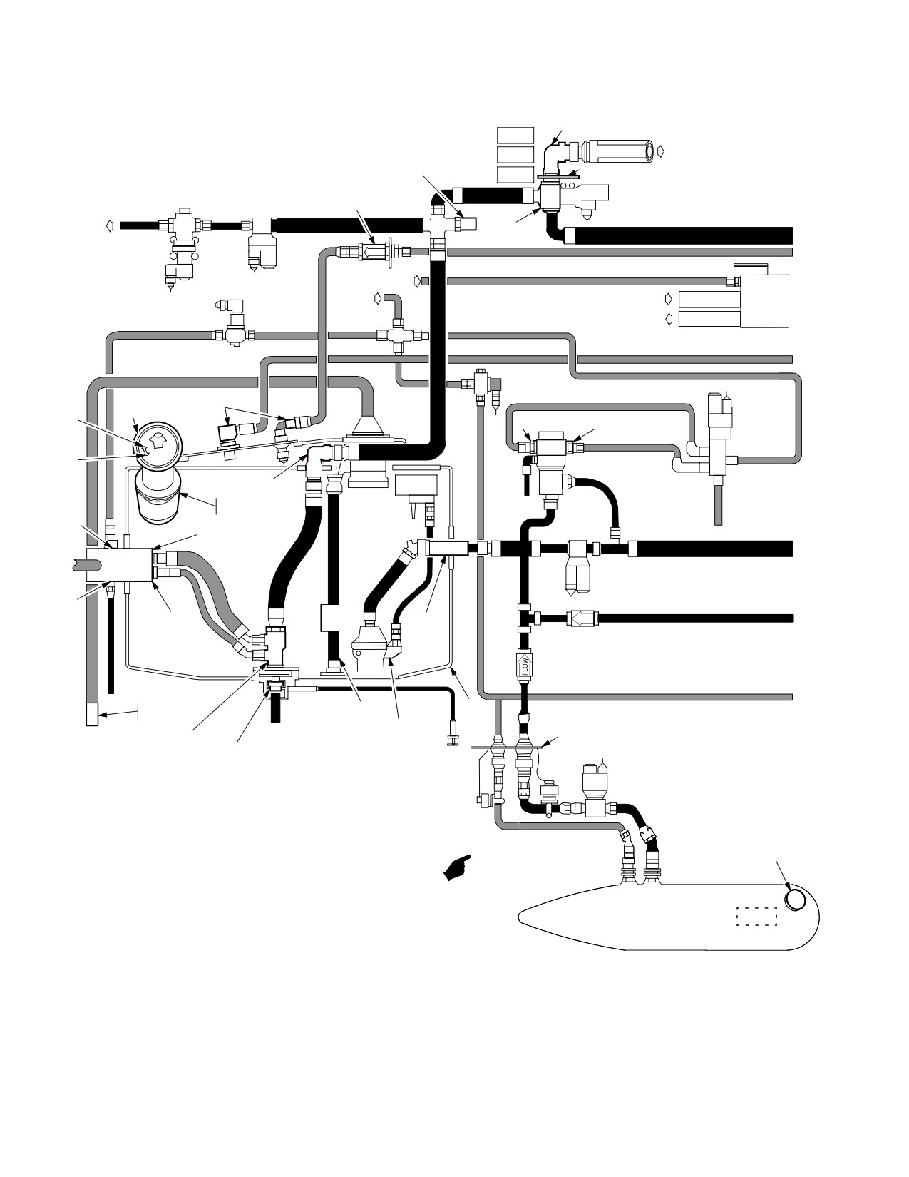
Figure 2-49. Fuel System (Sheet 1 of 2)
Use or disclosure of this information is subject to the restriction(s) on the title page of this document.
2-44
Change 1
TM 1-1520-251-10
ENG
TO ENG 1
CELL
LEFT SIDE
ÏÏ
X FEED
ÏÏBREAKAWAY VALVE
LEFT CROSSFEED
ENG
ENG FIREWALL
SHUTOFF VALVE
CELL
XFEED
ÔÔÔ
ÔÔÔ
INERT
NITROGEN
NITROGEN
INERTING
OUT
UNIT
FUEL VENT
SHUTOFF
VALVE
CLOSE
OPEN
DRAIN
SINGLE
GRAVIT
AIR VENT
POINT
FUEL/
FILLER
PORT
ADAPTER
DEFUEL
PORT
BREAKAWAY
AIR VENT/
(CAP)
CHECK
(CAP)
VALVE
PRESS RELIEF
VALVE
CLOSED
VALVE
CIRCUIT
ÏÏÏÏÏ
Ï
ÏÏ
ADAPTER
PRESSURE
(CAP)
FUELING
PILOT
Ï
ÔÔÔ
VALVE
Ï
MANIFOLD
Ï
ÔÔÔ
Ï
VENT TUBE
FUEL
BREAKAWAY
PRESS
Ô
Ï
VALVES
RELIEF
PORT
ÔÔÔ
ÔÔ
SCREEN
Ï
Ï
AUX
ÔÔÔ
LIGHTNING
ÏÔÔ
Ï
TANK
CHECK
ARRESTER
VALVE
Ï
LOW
Ï
LVL
BAFFLE
SENSOR
IAFS
Ï
FORWARD
CHECK
FLOW
FUEL
MANIFOLD
VALVES
CELL
ÏÏÏ
Ï
ÓÏÏÏÏÏÏÏÏÏÏÏÏÏÏÏ
O
BD
AFT
FUEL
FWD
V
ÏÏ
FUEL QTY
VENT
SUMP
FUEL QTY
SHUTOFF
XMTR
VALVE
XMTR
DRAIN
OVBD
VALVE
DRAIN
CHECK/THERMAL
PUSH
RELIEF VALVE
TO DRAIN
WING JOINT
Ô
Ô
FUEL
XFER
ÔÔÔ
SHUTOFF
VALVE
Ô
Ô
ÏÏÏÏÏÏÏÏÏÏÏ
GRAVITY
ÏÏÏÏÏÏÏÏÏÏÏÏ
FILLER
PORT
VENT
(CAP)
Ï
INTERNAL AUXILIARY FUEL SYSTEM
ÏÏ
PULL AWAY
100 U.S. GAL/130 U.S. GAL
N2 Ï
COUPLINGS
Ï
FUEL IN Ï
AUXILIARY
Ï
FUEL TANK(S)
FUEL QUANTITY
FUEL OUT
LEFT SIDE
EMPTY
INDICATING TAPE
Ï
ÏÏ
220 U.S. GAL
EACH
Ï
SUMP DRAIN
ÏÏ
ÏÏÏÏÏÏÏÏÏÏÏÏ
LBA02922B
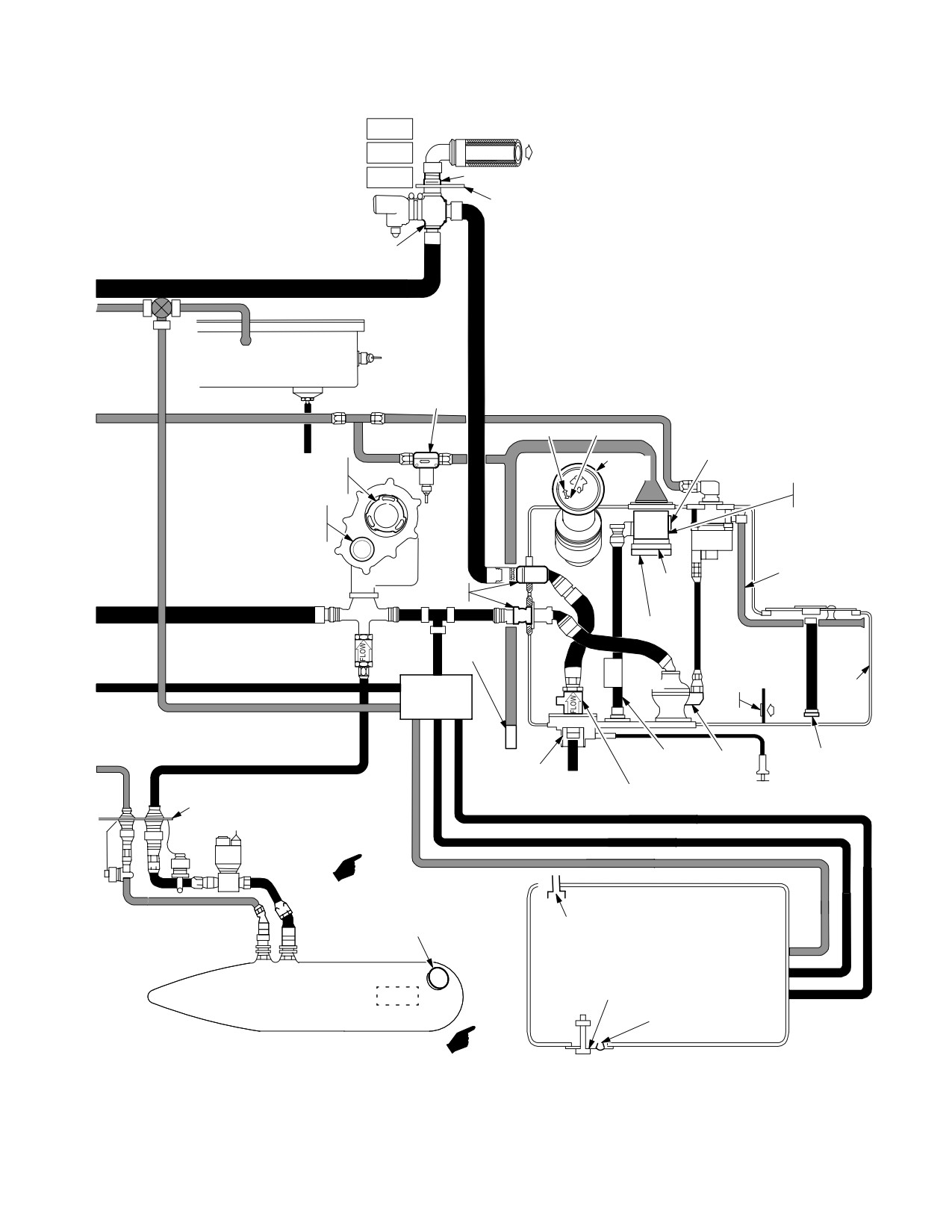
Figure 2 - 49. Fuel System (Sheet 2 of 2)
Use or disclosure of this information is subject to the restriction(s) on the title page of this document.
Change 2
2-45
TM 1-1520-251-10
2.56 FUEL FLOW RATE SUBSYSTEM
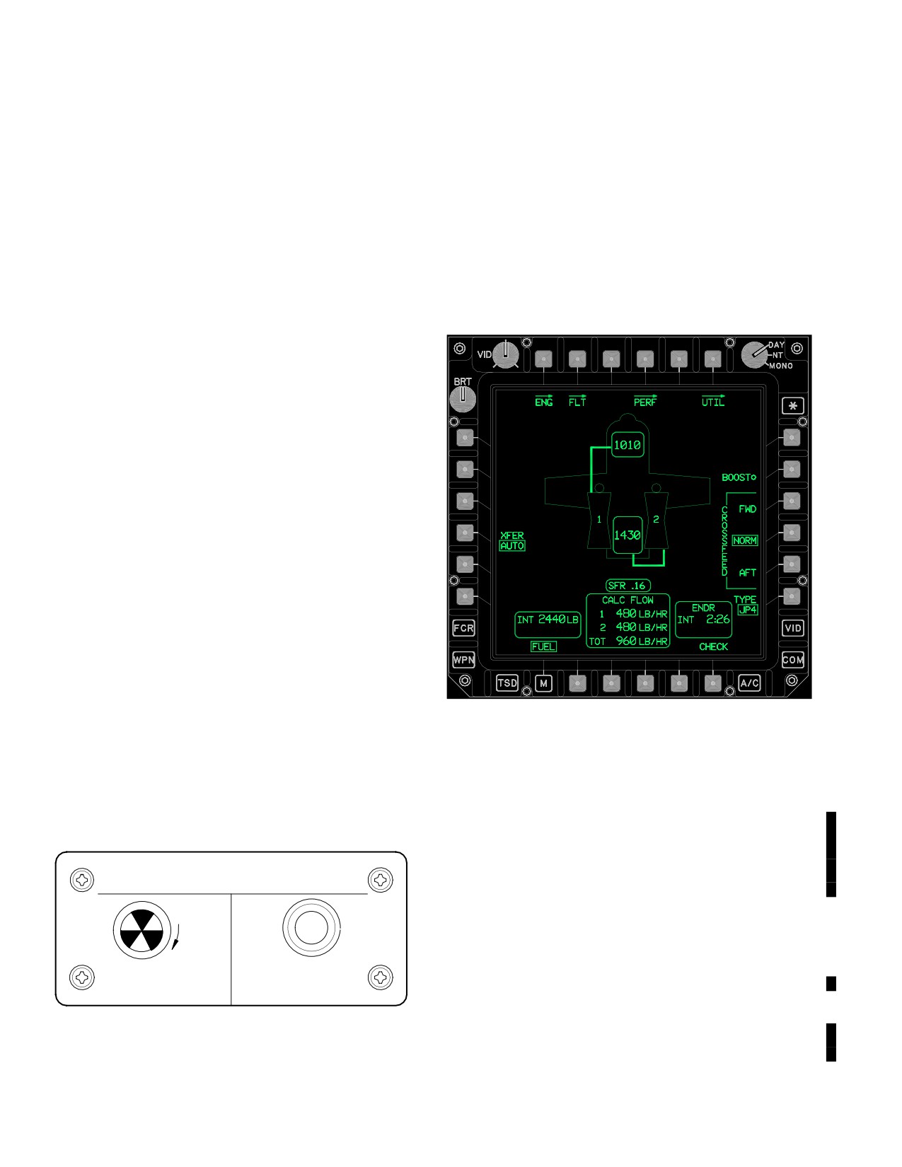
2.60 MPD FUEL MANAGEMENT PAGE
The fuel flow rate subsystem calculates engine fuel con-
The FUEL page displays all information and controls
sumption rate in lb/hr.
required to manage the internal fuel system (fig 2-51), the
external auxiliary system, and the internal auxiliary fuel
system (para 2.61 and 2.61A). The aircraft icon is laid out
2.57 APU FUEL SUBSYSTEM
in the same relative position as the physical equipment on
the aircraft. Status windows for fuel quantity, fuel flows
The APU fuel subsystem provides fuel to the APU. It con-
and aircraft endurance are located at the lower portion of
sists of an electrically driven APU boost pump which
the display. When a crewmember selects an operation,
draws fuel from the aft fuel cell and provides pressurized
the associated fuel lines will be displayed to provide a
fuel to the APU. The APU shut-off valve controls the flow
graphic representation of fuel routing.
of fuel from the aft cell to the APU via the boost pump.
2.58 REFUEL SUBSYSTEM
The refuel subsystem allows for pressurized refueling via
a single point adapter or a closed circuit adapter. It also
allows for gravity refueling via fuel cell filler ports for the
external fuel tanks and the forward and aft internal fuel
cells. The internal auxiliary fuel cell can only be refueled
via a pressurized adapter. The external refuel panel pro-
vides direct control of the refuel, vent, level control valve
units, and internal auxiliary fuel cell.
2.59 NITROGEN INERTING UNIT (NIU)
The NIU reduces fire hazards associated with fuel cell ul-
lages (air space) by filling the ullage with oxygen depleted
air. The NIU is self contained and automatically operated
whenever pressurized air and 115 Vac is available. A
press-to-test panel (fig 2-50) is located in the aft avionics
bay. The press-to-test button will only be valid when pres-
surized air and 115 Vac is applied to the system. The
press-to-test button will indicate that the NIU is not provid-
LBA5190
ing pressurized air. The NIU utilizes pressurized air from
the pressurized air manifold and purges about 70% of the
Figure
2-51.
Fuel Page - Standard Configuration
oxygen present. This air is then regulated into the aft fuel
cell and onward into the FWD fuel cell. When transferring
Bezel button selections are as follows:
fuel from the internal auxiliary fuel cell, all air is diverted to
the internal auxiliary fuel cell.
• T1
ENG button
• T2
FLT button
NITROGEN INERT MONITOR
• T4
PERF button
7311642315
• T6
UTIL button
RESET
• L4
XFER button
• R2
BOOST ON/OFF button
• R3
CROSSFEED FWD button
BLACK OK
PRESS TO TEST
• R4
CROSSFEED NORM button
WHITE FAIL
10 SEC MIN
• R5
CROSSFEED AFT button
LBA0452
• R6
TYPE button
Figure 2-50. NIU Test Panel
• B6
CHECK button
Use or disclosure of this information is subject to the restriction(s) on the title page of this document.
2-46
Change 2
TM 1-1520-251-10
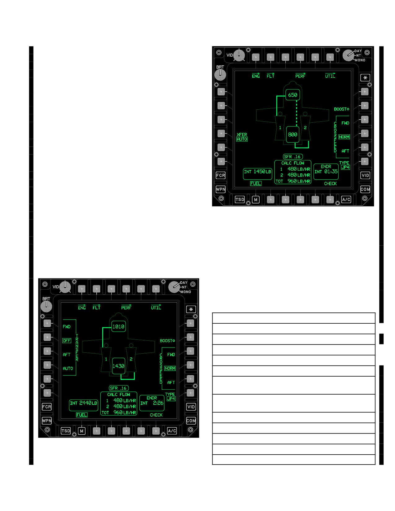
2.60.1
Transfer (XFER) Button. The XFER control
buttons (fig 2-52 ) allow crewmembers to balance the fuel
load between the forward and aft fuel cells. Four option
buttons, FWD, OFF, AFT, and AUTO, provide the means
to transfer fuel between the forward and aft fuel cells.
NOTE
Selecting either FWD or AFT button will
automatically override any previous internal
transfer selection.
a. Forward (FWD) XFER Button. The FWD button
allows the manual transfer of fuel from the aft fuel cell to
the forward fuel cell.
b. Off (OFF) XFER Button. The OFF button stops
the transfer of fuel between the forward fuel cell and the
aft fuel cell.
c. Aft (AFT) XFER Button. The AFT button allows
LBA5000
the manual transfer of fuel from the forward fuel cell to the
aft fuel cell.
d. Automatic (AUTO) XFER Button. The AUTO
button (fig 2-53) allows crewmembers to select automatic
Figure
2-53.
Automatic Fuel Transfer
fuel levelling between the forward and aft fuel cell (Table
2-6).
Table 2-6.
Automatic Fuel Levelling Conditions
(with AUTO selected)
BEGIN AUTO LEVELLING TO AFT TANK
1. Engines 1 and 2 are running.
2. APU or ENG bleed air is on.
3. Aft Fuel level <814 lb
4. No Fwd Fuel Low level indication.
5. Fwd Fuel quantity >280 lb
6. If Fwd Fuel quantity >500 lb and is >100 lb more
than Aft Fuel quantity.
7. If Fwd Fuel quantity <500 lb and is >50 lb more
than Aft Fuel quantity.
HALT AUTO LEVELLING TO AFT TANK
1. Fwd Fuel low level Caution.
LBA5189
2. Fuel split <20 lb
3. APU is off and ENG bleed air is off
Figure 2-52. Fuel Transfer Options
Use or disclosure of this information is subject to the restriction(s) on the title page of this document.
Change 1
2-47
TM 1-1520-251-10
Table 2-6. Automatic Fuel Levelling Conditions
WHITE for three seconds upon change of state, then they
(with AUTO selected) (cont)
are displayed in GREEN.
b. Normal (NORM) CROSSFEED Button. The
AUTO LEVELLING TO FWD TANK
NORM button routes fuel from the forward fuel cell to en-
1. Engines 1 or 2 are running.
gine 1 and aft fuel cell to engine 2. The aircraft icon re-
flects this state by providing a graphic representation of
2. APU or ENG bleed air is on.
the fuel cell lines. The lines are displayed in WHITE for
3. Fwd Fuel level <814 lb
three seconds upon change of state, then they are dis-
4. No Aft Fuel Low level indication.
played in GREEN.
5. Aft Fuel quantity >240 lb
c. Aft (AFT) CROSSFEED Button. The AFT button
6. If Aft Fuel quantity >500 lb and is >100 lb more
routes fuel from the aft fuel cell to engine 1 and 2. The air-
than Fwd Fuel quantity.
craft icon reflects the AFT selection by providing a graphic
representation of the aft fuel cell routing fuel to engine 1
7. If Aft Fuel quantity <500 lb and is >50 lb more
and 2. The lines are displayed in WHITE for three seconds
than Fwd Fuel quantity.
upon change of state, then they are displayed in GREEN.
2.60.5 Fuel Type Selection. The system will default to
HALT AUTO LEVELLING TO FWD TANK
fuel type JP-8. The operator will have the option to select
1. Aft Fuel low level Caution.
the fuel type other than JP-8 through the TYPE button.
2. Fuel split <20 lb
Selection of the TYPE button will display the fuel type
selections JP-8, JP-5, and JP-4. Fuel TYPE entries affect
3. Fwd tank is full
external fuel tank and non - probed internal auxiliary fuel
4. APU is off and ENG bleed air is off
cell quantity computations by changing fuel density val-
ues. Internal fuel quantity densities are sensed automati-
2.60.2 Transfer Status. When the internal transfer
cally. The fuel TYPE also affects the calculated fuel flow.
system is commanded on, the fuel transfer line will be dis-
2.60.6 Status Windows. The following status windows
played and marquee to indicate direction of transfer. The
are displayed during normal aircraft fuel configuration:
fuel transfer line is displayed in WHITE for three seconds
upon activation and then turns green. Transfer status is
a. Forward (FWD) Fuel Cell Quantity. The FWD
also indicated during automatic transfer. Fuel transfer is
fuel quantity is displayed in green at the top area of the
stopped when fuel split is less than 20 lb.
aircraft icon and provides forward fuel cell quantity. The
forward fuel cell quantity is displayed in YELLOW when
2.60.3 Boost (BOOST) ON/OFF Button. The BOOST
the cell is detected as low level. The FWD fuel cell display
button controls boost pump operation. The BOOST button
range is 0 to 1100 lb and depicts in units of 10 lb.
provides an ON dot to the right of the BOOST label when
b. Aft (AFT) Fuel Cell Quantity. The AFT fuel cell
the boost has been activated. When the boost pump has
quantity is displayed in green in the bottom area of the air-
been actioned on the system automatically sets the fuel
craft icon and provides aft fuel cell quantity. The aft fuel
CROSSFEED to AFT and the CROSSFEED AFT button.
cell quantity is displayed in YELLOW when the cell is de-
tected as low level. The AFT fuel cell display range is 0 to
2.60.4 Fuel Page Crossfeed Selections. Three se-
1500 lb and depicts in units of 10 lb.
lectable buttons, FWD, NORM and AFT, will allow selec-
c. Internal
(INT) Fuel Quantity Status Win-
tion of which cells will feed each engine. Both engines will
dow. The INT fuel quantity data field is displayed in the
feed from either the forward or aft cell when selected. This
lower left corner of the FUEL page and provides the crew-
allows the pilot an emergency means to continue flight to
member the total fuel quantity of the forward and aft fuel
a safe area after sustaining fuel system damage. Cross-
cells only. The internal fuel quantity is displayed in YEL-
feed routing can be used on the ground to control fuel feed
LOW when either the forward or aft fuel cell quantity is dis-
during hot refueling.
played in YELLOW. Internal fuel quantity is displayed
within a range of 0 to 2600 lb in increments of 10 lb. The
a. Forward (FWD) CROSSFEED Button. The
internal fuel quantity is monitored by internal sensors and
FWD button routes fuel from the forward fuel cell to engine
does not require any operator input.
1 and 2. The aircraft icon reflects the FWD selection by
providing a graphic representation of the forward fuel cell
d. Endurance (ENDR) Status Window. The ENDR
routing fuel to engine 1 and 2. The lines are displayed in
status window is displayed in the bottom right corner of
Use or disclosure of this information is subject to the restriction(s) on the title page of this document.
2-48
Change 1
TM 1-1520-251-10
the page and provides the amount of fuel (forward fuel cell
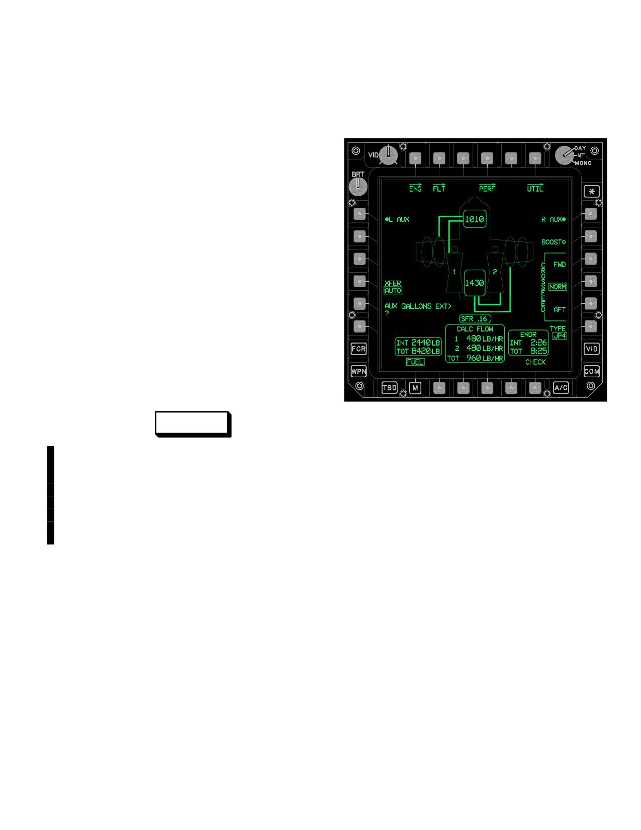
• L1
L AUX Fuel Transfer ON/OFF button
and aft fuel cell) remaining in time. Endurance is based on
• L5
AUX GALLONS EXT button
calculated fuel flow and will vary based upon power ap-
plication. The remaining time is displayed in WHITE when
• R1
R AUX Fuel Transfer ON/OFF button
it is less than 20 minutes.
e. Fuel Flow (CALC FLOW) Status Window. The
CALC FLOW is displayed in the bottom center of the
FUEL page and provides crewmembers with the uncor-
rected main engines calculated fuel flow in lb per hour
(LB/HR). Fuel flow is calculated based on static/free air
temperature, engine torque, pressure altitude, fuel type,
and engine type. The engine 1 & 2 fuel flow data field has
a display range of 0 to 950 LB/HR in increments of 5 LB/
HR. The total fuel flow data field has a display range of 0
to 1900 LB/HR in increments of 5 LB/HR.
f. Specific Fuel Range
(SFR) Status Win-
dow. The SFR is displayed above the CALC FLOW sta-
tus window. SFR is a calculation of ground speed in knots
divided by the total fuel uncorrected flow for the present
power setting, and is used to determine power settings for
optimum fuel economy during cruise. SFR will display only
when airspeed is ten kts or above.
2.61 FUEL PAGE EXTERNAL AUXILIARY FUEL
TANK SELECTION
LBA2565B
WARNING
Figure
2-53A.
Fuel Page - External Auxiliary Fuel
Tanks Installed
Extended Range Fuel System (ERFS)
tanks do not have any ballistic protec-
tion and are vulnerable to high-speed
2.61.1
External Auxiliary Fuel Transfer Opera-
projectiles. Projectiles passing through
tion.
External fuel transfer can be accessed on the
a fueled ERFS tank can generate a fuel
FUEL page. If tank(s) are installed on the left side of the
driven fuselage fire and or cause the
aircraft, L AUX selection is displayed. If tank(s) are
tank to detonate with the potential for
installed on the right side of the aircraft, R AUX selection
losing both thw aircrew and aircraft.
is displayed. A crewmember can select one or both auxil-
iary fuel tank transfers.
The fuel system will detect the presence and location of
2.61.2 LEFT and RIGHT AUX ON/OFF Buttons. The
external auxiliary tanks on the aircraft and display icons
AUX on/off buttons start or stop fuel transfer from left and/
representing the external tanks on the FUEL page (fig
or right tanks. The left and/or right fuel tanks must be
2-53A). A float switch in each tank indicates when that
installed on the aircraft for the AUX buttons to be dis-
tank is empty and the FUEL page displays a WHITE indi-
played. When an AUX button is activated, the respective
cator E on the center of the tank icon.
fuel line graphic will be shown and the ON dot will be dis-
Additional Bezel buttons available when auxiliary fuel
played. The lines are displayed in WHITE for three se-
tanks are installed are:
conds upon activation, then they are displayed in GREEN.
Use or disclosure of this information is subject to the restriction(s) on the title page of this document.
Change 4
2-49
TM 1-1520-251-10
NOTE
Auxiliary fuel quantity must be added
through the AUX GALLONS EXT data entry
button on the FUEL page.
a. Either left or right aux fuel transfer mode will be
commanded to off when any of the following occurs:
• A crewmember deselects aux transfer via the
MPD.
• The SP loses communication with both WPs.
• The auxiliary tanks on that side of the aircraft
indicate empty.
• AC power is lost.
b. If an internal fuel transfer is commanded, the exter-
nal auxiliary fuel transfer will be suspended until the the
forward/aft transfer is complete. The MPD R/L AUX but-
ton will display the auxiliary transfer mode as ON while in
the suspended mode. [
BLK 2
Additionally, the external
fuel transfer lines will be displayed in partial intensity
LBA5026
green while suspended.] A crewmember may select auxil-
iary transfer on and off while in the suspended mode. This
Figure 2-53B. Fuel Page - Internal Auxiliary Fuel
applies to both manual and automatic internal fuel cell
Tank Installed
transfers.
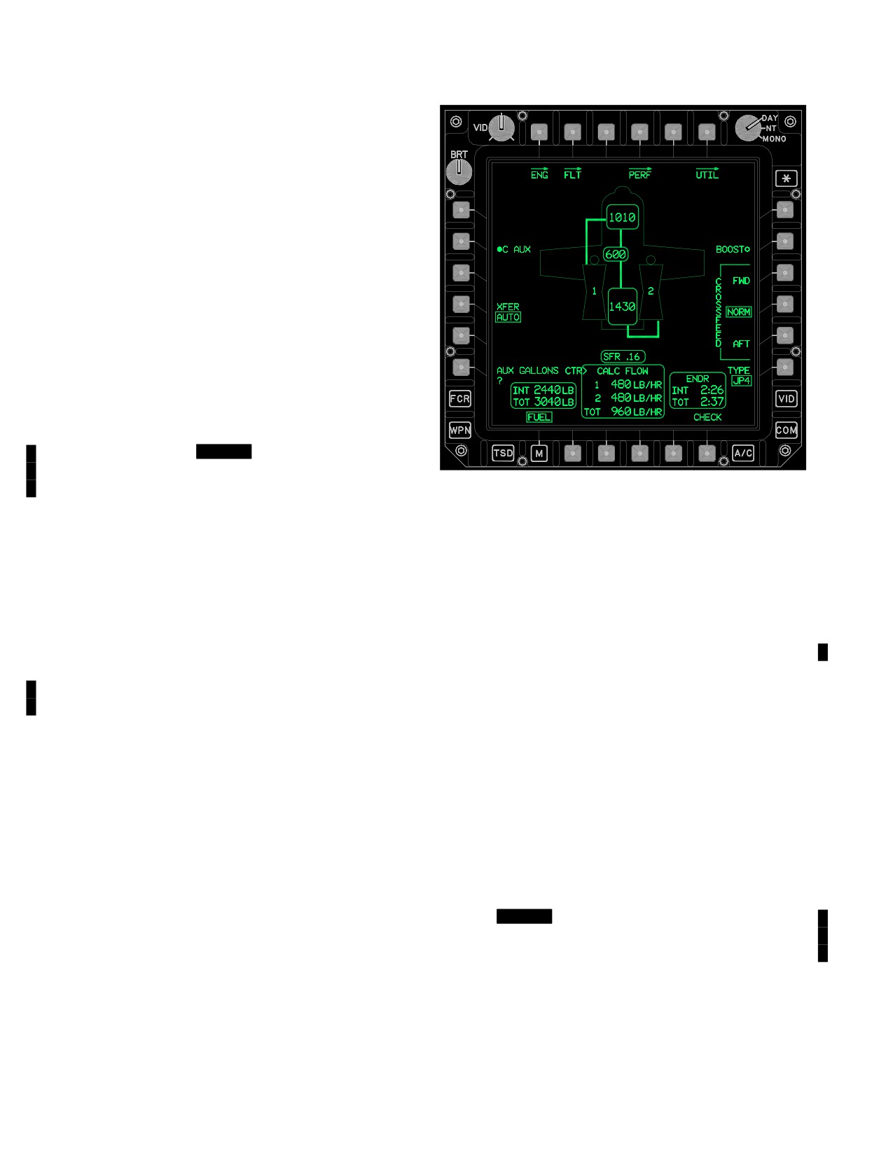
Additional Bezel buttons available when an internal auxil-
2.61A FUEL PAGE INTERNAL AUXILIARY FUEL
iary fuel cell is installed are:
TANK INSTALLED
• L2
C AUX Fuel Transfer ON/OFF button
• L6
AUX GALLONS CTR button (unprobed)
The fuel system will detect the presence and configuration
of the internal auxiliary fuel system on the aircraft and dis-
2.61A.1 Internal Auxiliary Fuel Transfer Opera-
play an icon representing the internal auxiliary fuel cell on
tion. Internal auxiliary fuel transfer can be accessed on
the FUEL page (fig 2-53B). A pressure switch indicates
the FUEL page. When an internal auxiliary fuel cell is
when the tank is empty, an advisory is displayed on the
installed, the C AUX selection is displayed.
UFD/EUFD, and the FUEL page displays a WHITE indica-
a. The internal aux fuel transfer mode will be com-
tor E on the center of the tank icon when empty.
manded to off when any of the following occurs:
• A crewmember deselects aux transfer via the
MPD.
• AC power is lost.
• The auxiliary tank is indicated as empty or failed.
b. If either an internal fuel transfer or an external aux-
iliary transfer is commanded, the internal auxiliary fuel
transfer will be suspended until the the forward/aft/exter-
nal transfer is complete. The MPD ON button will display
the auxiliary transfer mode as on while in the suspended
mode. [
BLK 2
Additionally, the external fuel transfer
lines will be displayed in partial intensity green while sus-
pended. A crewmember may select auxiliary transfer ON
and OFF while in the suspended mode.] This applies to
both manual and automatic internal fuel cell transfers.
Use or disclosure of this information is subject to the restriction(s) on the title page of this document.
2-50
Change 2
TM 1-1520-251-10
2.61A.2 Center AUX On/Off Button. The C AUX on/
off button starts or stops the fuel transfer from the center
tank. The center fuel tank must be installed on the aircraft
for the C AUX button to be displayed. When the C AUX
button is activated, the fuel line graphic will be displayed
and the on dot will be displayed. Lines are displayed in
WHITE for three seconds upon activation, then they are
displayed in GREEN. Fuel is transferred from the internal
auxiliary fuel cell to both the forward and aft fuel cells si-
multaneously.
NOTE
Unless probed, internal auxiliary fuel quanti-
ty must be added through the AUX GAL-
LONS CTR data entry button on the FUEL
page.
2.61A.3 Status Windows. Additional status is dis-
played when auxiliary fuel tanks are installed. This data
LBA5187
field will only be displayed when the system has detected
that there are external tanks located on the aircraft.
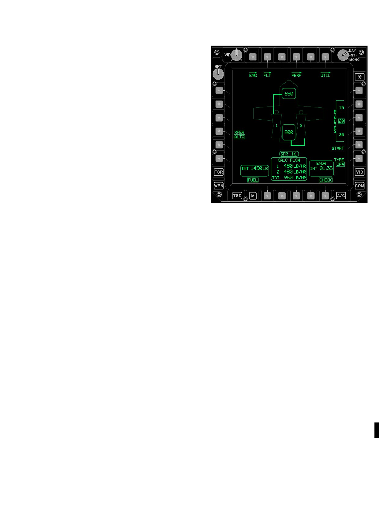
Figure
2-54.
Fuel Page - CHECK Format
a. Total (TOT) Fuel Quantity Status. The TOT
quantity is displayed in the bottom left corner of the FUEL
page and provides the crewmember the total fuel quantity
of the forward, aft, and all auxiliary tanks. This data field
Additional bezel buttons available when CHECK is se-
will only be displayed when the system has detected that
lected:
there are external tanks located on the aircraft. The total
fuel quantity data field has a display range of 0 to 8840 lb
• R2
15 (MINUTES) button
in increments of 10 lb. Auxiliary fuel quantity must be add-
• R3
20 (MINUTES) button
ed through the AUX GALLONS EXT and/or AUX GAL-
LONS CTR data entry buttons.
• R4
30 (MINUTES) button
• R5
START/STOP button
b. Total Endurance (ENDR TOT) Status. The
ENDR TOT status window is displayed in the bottom right
2.62.2
Fuel Check Operation. Either crewmember
corner of the FUEL page and provides the total endur-
may initiate a fuel check by selecting the CHECK button,
ance based on the fuel remaining in the forward cell, aft
pressing the desired MINUTES (15, 20, or 30) button and
cell, and all auxiliary fuel tanks. Total endurance is based
then pressing the START button. A status window in the
upper left corner will display the START time, RUN time,
on calculated fuel flow and will vary based upon power ap-
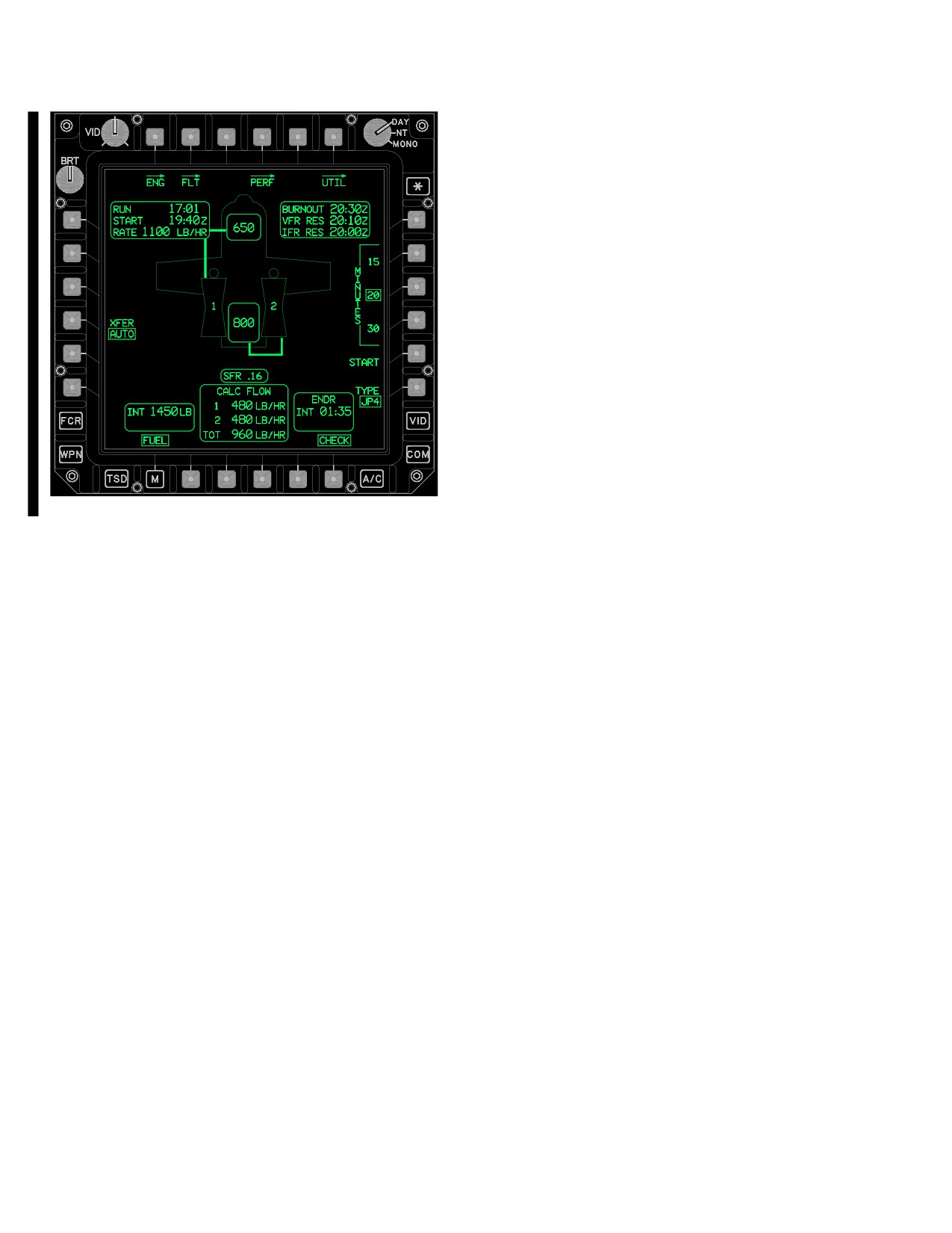
and burn RATE. Upon completion of the check (fig 2-55),
plication.
a status window, in the upper right corner, will display cal-
culated BURNOUT, VFR RES, and IFR RES times in the
2.62 FUEL CHECK
currently selected time format, Zulu or local. The fuel
check may be terminated prior to the selected MINUTES
by selecting STOP. If neither crewmember is viewing the
2.62.1 Fuel CHECK Button. When selected, the fuel
CHECK format at the conclusion of the check, an advisory
CHECK button allows the calculation of (fig 2-54) burnout,
will appear on the UFD/EUFD. Selection of the CHECK
VFR reserve, and IFR reserve times, based on the fuel
format by either crewmember will remove the advisory.
quantity change, during the selected 15, 20, or 30 minute
Additional fuel checks may be initiated by selecting the
intervals.
START button.
Use or disclosure of this information is subject to the restriction(s) on the title page of this document.
Change 2
2-50.1
TM 1-1520-251-10
LBA5188
Figure 2-55. Fuel Page - CHECK Complete
Use or disclosure of this information is subject to the restriction(s) on the title page of this document.
2-50.2
Change 2
TM 1-1520-251-10
Section V. FLIGHT CONTROL SYSTEM
2.63 FLIGHT CONTROL SYSTEM
measure the positions of the controls and provide this in-
formation to the FMC. Hydraulic power is supplied by two
The AH-64D employs an irreversible hydromechanical
independent hydraulic pumps which are mounted on the
flight control system (fig 2-56). The hydromechanical sys-
accessory gearbox of the main transmission. The FMC
tem is mechanically activated with conventional cyclic,
provides rate damping, command augmentation, attitude
collective, and directional controls, through a series of
and altitude hold within the ± 10% (20% forward pitch) au-
push pull tubes and bellcranks which activate four air-
thority of the system. An electrically actuated horizontal
frame-mounted hydraulic servocylinders. The four hy-
stabilator is attached to the lower aft portion of the vertical
draulic servocylinders control longitudinal/lateral cyclic,
stabilizer. Movement of the stabilator is commanded by
main rotor collective, and tail rotor pitch. The servocylind-
the FMC in either a manual or automatic mode. A trim feel
ers incorporate integral Stability and Command Aug-
system is incorporated in both the cyclic and pedals pro-
mentation System (SCAS) actuators which are active
whenever the Flight Management Computer (FMC) is on.
viding a control force gradient with control displacement
Linear Variable Differential Transducers (LVDTs) are in-
from a selected trim position. A trim release switch allows
corporated into each of the flight control axes. The LVDTs
momentary disengagement of the trim feel system.
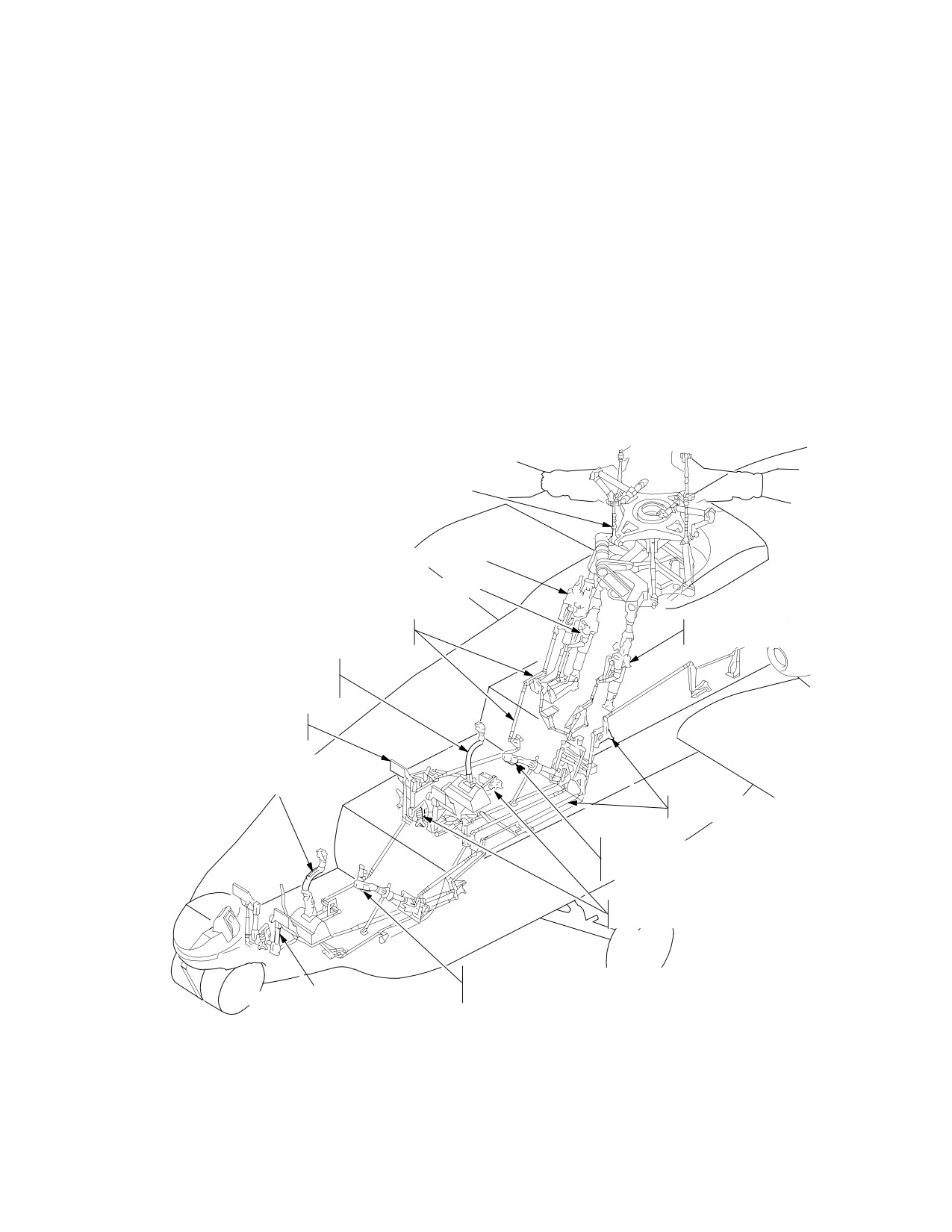
UPPER FLIGHT CONTROLS
LONGITUDINAL SERVOCYLINDER AND BUCS SHEAR PIN
COLLECTIVE SERVOCYLINDER AND BUCS SHEAR PIN
LONGITUDINAL
LATERAL SERVOCYLINDER AND
MECHANICAL CONTROL LINKAGE
BUCS SHEAR PIN
PILOT CYCLIC CONTROL STICK
(LVDT, AND ARDD ASSEMBLIES
UNDER COVER)
PILOT DIRECTIONAL CONTROL PEDALS
(LVDT, AND ARDD ASSEMBLIES UNDER
COVER)
CPG CYCLIC CONTROL STICK
(LVDT, AND ARDD,
ASSEMBLIES UNDER COVER)
LATERAL
MECHANICAL CONTROL LINKAGE
PILOT COLLECTIVE CONTROL STICK
(LVDT, ARDD ASSEMBLIES AND 1G
SPRING ASSEMBLIES UNDER COVER).
(PILOT ONLY) LATERAL AND LONGITUDINAL
FEEL SPRING ASSEMBLIES AND MAGNETIC BRAKES
CPG COLLECTIVE CONTROL STICK
(LVDT, ARDD ASSEMBLIES AND 1G
CPG DIRECTIONAL CONTROL PEDALS
SPRING ASSEMBLIES
(LVDT, AND ARDD ASSEMBLIES
UNDER COVER)
LBA0475
UNDER COVER)
Figure 2-56. Flight Controls System
Use or disclosure of this information is subject to the restriction(s) on the title page of this document.
2-51
TM 1-1520-251-10
2.64 CYCLIC CONTROL SUBSYSTEM
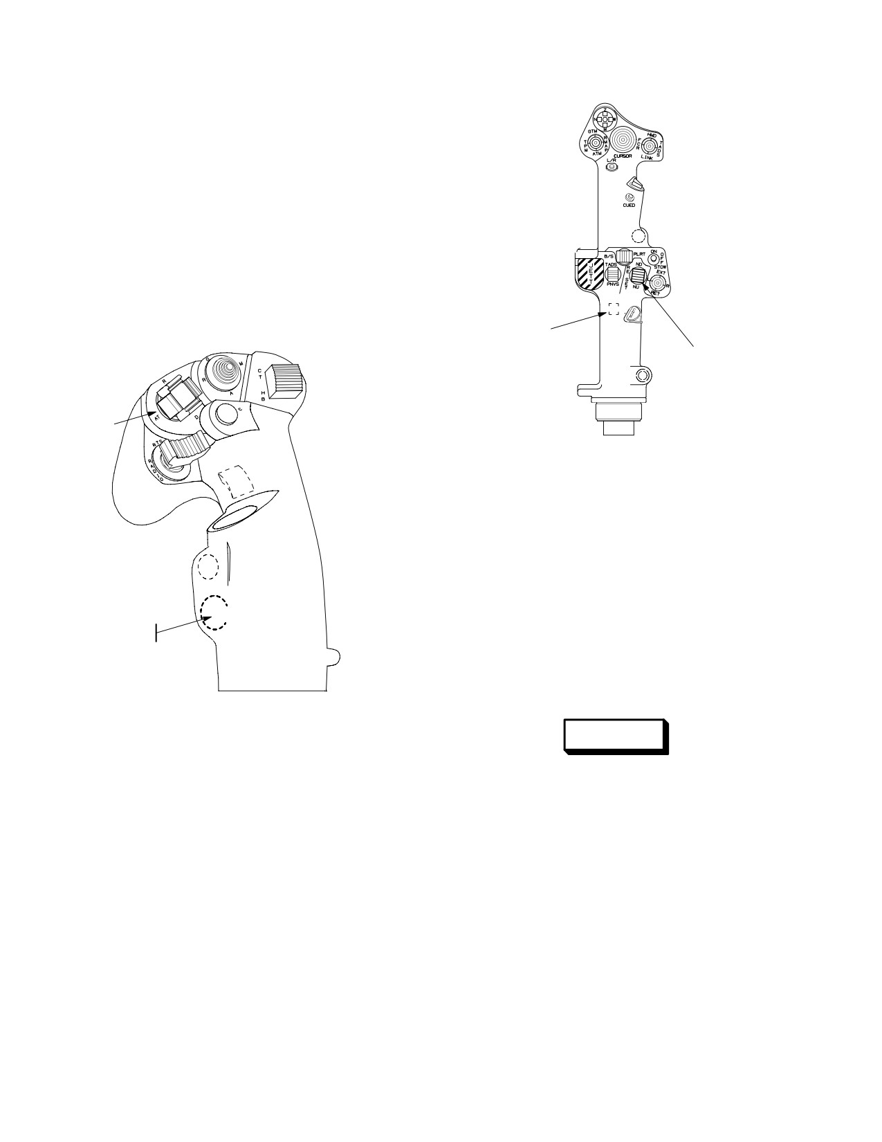
Conventional cyclic control sticks (fig 2-57) are attached
to individual support assemblies which house the primary
longitudinal and lateral control stops and two LVDT’s. The
cyclic stick grips incorporate the force trim release, hold
mode switch, and the FMC release button. The CPG cy-
clic stick incorporates a fold down mechanism to minimize
interference when the CPG is not flying the aircraft. The
CPG cyclic stick is fully effective in either the up or down
position.
BUCS SELECT
TRIGGER
STABILATOR
(CPG ONLY)
CONTROL SWITCH
FORCE
TRIM/HOLD
MODE
LBA2082
SWITCH
Figure 2-58. Collective Grip Flight Control
Switches
2.66 DIRECTIONAL CONTROL SUBSYSTEM
The directional control system consists of pedals in each
crew station which activate the tail rotor servocylinder lo-
cated in the vertical stabilizer. Attached to each directional
pedal assembly is a control stop and one LVDT. Pedal ad-
justment is accomplished through a lock/unlock lever lo-
FMC
RELEASE
cated between and aft of the pedals. Wheel brakes are in-
corporated into the upper portion of the control pedals.
LBA2081
2.67 FORCE TRIM SUBSYSTEM
WARNING
Figure 2-57. Cyclic Grip Flight Control Switches
Even with the force trim ON, the flight
controls must be monitored at all times
2.65 COLLECTIVE CONTROL SUBSYSTEM
while the rotors are turning. When force
trim is selected OFF from the A/C UTIL
page, no force gradient will be available
The collective pitch control system consists of identical
to position the cyclic. Hands off cyclic
collective grips (fig 2-58) in each cockpit. Movement of the
capability will NOT be available.
collective is transmitted to the collective servocylinder for
control of main rotor blade pitch angle and to the load de-
A force trim system is incorporated in the longitudinal, lat-
mand spindle of each engines hydromechanical unit for
eral and directional control axes. The force trim system is
load anticipation. Located at the base of each collective
designed to keep the controls in the position that the pilot
control is the primary control stop, an LVDT, and a 1G bal-
or CPG selects. The force trim system is located beneath
ance spring. The 1G spring counterbalances the weight of
the pilots floor. The Force Trim Release (FTR) switch al-
the collective control sticks. Both collective control sticks
lows the crewmember to momentarily interrupt the sys-
employ a friction adjustment twist grip. The collective con-
tem. When interrupted, the force trim brakes allow move-
trol grips also provide the stabilator control switch.
ment of the controls without any resistance. When
Use or disclosure of this information is subject to the restriction(s) on the title page of this document.
2-52
TM 1-1520-251-10
engaged, the magnetic brakes lock and the spring assem-
c. The “?” symbol is displayed in red just above the
blies resist control movement. DC electrical power is re-
symbol when the stabilator has been detected as failed
quired for operation of the system and a complete failure
and the position of the stabilator is unknown.
would disable the system and allow the cyclic and pedals
to move freely without resistance from the trim feel
springs.
2.68 HORIZONTAL STABILATOR
The stabilator provides pitch trim angle control and im-
proves over-the-nose visibility at low airspeeds. The stabi-
lator has both an automatic and a manual mode. The au-
tomatic mode is engaged following power-up of the
aircraft and is controlled by the FMC. Two modes are
available within the automatic control system. The auto -
mode provides automatic scheduling in accordance with
collective position, airspeed, and pitch rate. The Nap Of
the Earth/Approach (NOE/A) mode commands the stabi-
lator to 25° trailing edge down, up to a speed of 80 KTAS.
At speeds greater than this, the stabilator schedule re-
verts to the auto - mode. A manual mode is selectable at
airspeeds less than 80 KTAS, or is engaged when the au-
tomatic system fails. Manual control or stabilator reset is
affected through the stabilator control switch on the collec-
tive flight grip. Depressing the stabilator control switch will
LBA2083A
reset the stabilator to the AUTO mode. Stabilator position-
ing is accomplished by two tandem DC motor actuators.
Stabilator position information (in degrees) is presented
Figure
2-59.
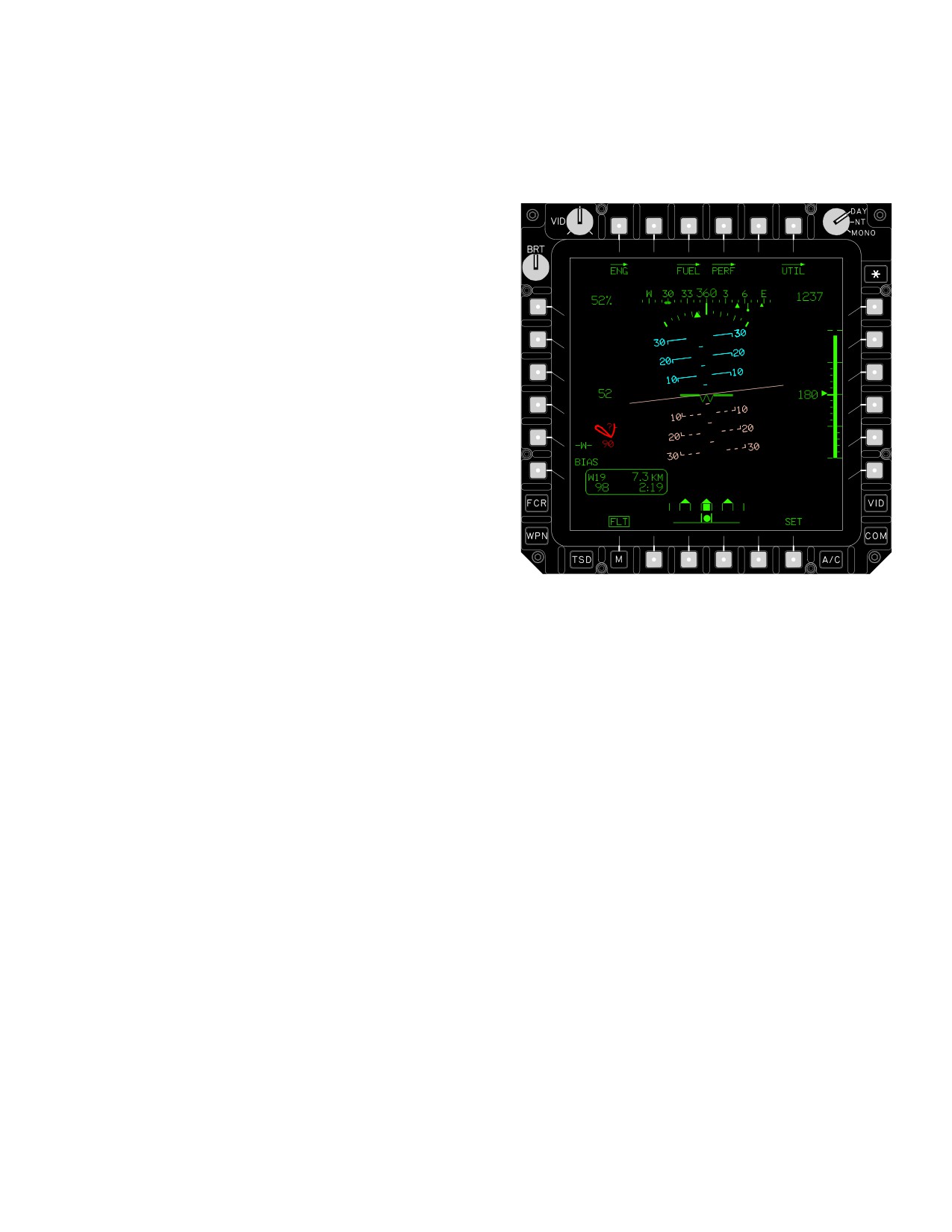
FLT Page - Stabilator Symbol
on the SYS page, and relative position information on the
the FLT page and on the FLT SET page. The stabilator
trailing edge incorporates Gurney flaps for increased
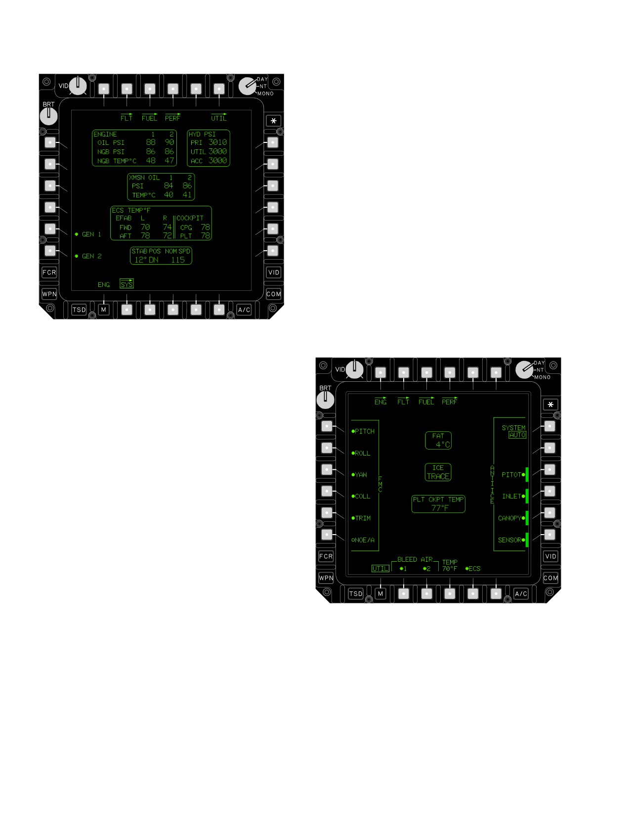
2.68.2 Engine SYS Page. Indications in the Stabilator
aerodynamic stabilization.
Status Window on the engine SYS page (fig 2-60) are as
follows:
2.68.1 FLT and FLT SET Page. Stabilator indications
on the FLT and FLT SET (fig 2-59) pages are as follows:
a. The stabilator trailing edge angle is displayed at a
range from - 10° up to 35° down. A “?” symbol is displayed
when the stabilator has been detected as failed and the
a. The stabilator symbol is displayed in WHITE with-
position of the stabilator is unknown.
out airspeed information when the stabilator is operating
in the manual mode. When the stabilator has been de-
tected as failed, the stabilator symbol is displayed in YEL-
b. The stabilator orientation is presented as “UP” or
LOW along with the limiting TAS for the current stabilator
“DN” (down). This indication is not presented when the
position. The stabilator symbol and TAS limit are dis-
stabilator has been detected as failed.
played in RED when the current TAS is greater than the
TAS limit.
c. The nominal TAS limit is displayed to indicate the
maximum operating airspeed limit for the current trailing
b. The nominal true airspeed (TAS) limit is displayed
edge angle. The limit is displayed in WHITE when the sta-
just below the symbol to indicate the maximum operating
bilator is operating in the manual mode; the limit is dis-
airspeed limit when the stabilator has been detected as
played in YELLOW when the stabilator has been detected
failed. When the position of the stabilator is unknown, the
as failed. When the position of the stabilator is unknown,
nominal airspeed limit will default to the TAS equivalent of
the nominal airspeed limit will default to the TAS equiva-
90 KIAS. When FMC data is not valid, the nominal IAS
lent of 90 KIAS. When FMC data is not valid, the nominal
limit is displayed.
IAS limit is displayed.
Use or disclosure of this information is subject to the restriction(s) on the title page of this document.
2-53
TM 1-1520-251-10
the radar or barometric altitude hold mode. Attitude and
Altitude hold switches are momentary ON/OFF. Selecting
the switch once turns the mode ON; selecting the switch a
second time turns the mode OFF. The collective control
flight grip incorporates a switch for control of the horizontal
stabilator. The three position switch allows the stabilator
to be moved throughout its complete range and to be re-
set to the automatic mode. When the stabilator is in the
NOE/APPR mode, pressing the stabilator RESET button
will disengage the NOE/APPR mode.
2.70 MPD FMC CONTROLS
The A/C UTIL page (fig 2-61) displays controls for the
FMC. The controls have two possible initialization condi-
tions; ground and in - flight. If startup occurs in - flight, the
FMC controls will be set to the state they were in before
the power interrupt. If startup occurs on the ground, all
modes and controls are on except the NOE/Approach
mode. The Stability and Command Augmentation System
LBA2540A
(SCAS) will automatically be engaged following EGI align-
ment.
Figure 2-60. SYS Page - Stabilator Status
2.69
CONTROL SWITCHES
Control switches are integrated into the cyclic and collec-
tive to allow hands-on cyclic and collective manipulation of
the systems. The cyclic grip (fig 2-57) incorporates an
Flight Management Computer (FMC) release button and
the Force Trim/Hold Mode switch. The FMC release but-
ton immediately disengages the SCAS if pressed. The
Force Trim/Hold Mode switch is a five position center
maintained switch. In the center position, SCAS, force trim
and the hold mode, if selected, are active. Pressing the
switch up (forward) to the Release (R) position interrupts
force trim and the attitude hold mode references if the hold
modes are selected. Releasing the force trim switch re-
engages the force trim at the new location and resets the
attitude hold modes to the new conditions. Pressing the
switch down to the Disengage (D) position disengages
any selected hold modes. Pressing the switch to the left to
the attitude (AT) position engages/disengages the posi-
LBA2083
tion, velocity, or attitude hold mode. Pressing the switch to
the right to the altitude (AL) position engages/disengages
Figure
2-61.
UTIL Page
Use or disclosure of this information is subject to the restriction(s) on the title page of this document.
2-54
TM 1-1520-251-10
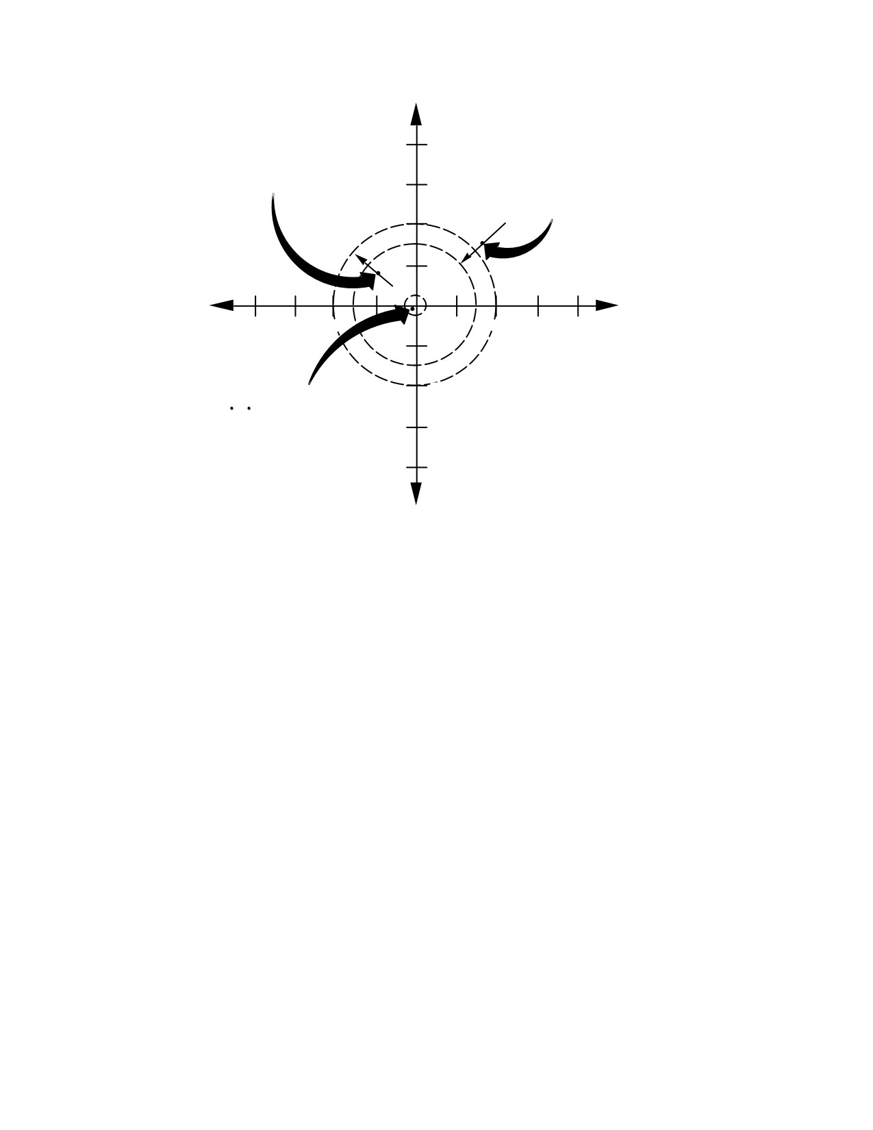
2.71 STABILITY AND COMMAND AUGMENTATION
The hold modes are divided into altitude and attitude hold
SUBSYSTEM (SCAS)
(fig 2-62). The modes are activated through the five - posi-
tion Force Trim / Hold Mode switch. Upon activation, the
NOTE
pilot is provided with a visual indication that the mode is
The FMC is susceptible to electrical switch-
engaged (see Section XIV). Upon disengagement, the
ing transients at voltage levels below that
flight cues are removed and a tone sounds. The attitude
found on the aircraft. Susceptibility is char-
hold mode can be engaged anytime the SCAS channels
acterized by uncommanded disengagement
and Force Trim are on. However, the mode is only active
of SCAS functions in some or all axes.
in-flight. The pilot can “fly through” the hold modes in any
or all axes. When the FMC senses control motion above
The SCAS has three functions; Stabilization System,
the breakout in any axis or the force trim is momentarily
Command System, and the Hold modes. The Stabilization
released, that axis reference is no longer held. When the
System provides rate damping in all axes. Additionally, the
controls are returned to trim, the FMC captures and holds
Stabilization System automatically provides turn coor-
the new reference.
dination at speeds greater than 40 kts, and dampens any
atmospheric upsets to the airframe in order to stabilize the
aircraft. The Command System provides a uniform aircraft
response for a given control input at all airspeeds. The
Hold modes are designed to provide limited hands-off
flight and decrease pilot workload. The FMC monitors all
inputs and will disengage on an axis-by-axis basis if a fail-
ure occurs.
2.72 HOLD MODES
WARNING
• Hold modes operate through the
SCAS system, and as such provide
only limited capability. The system is
not capable of maintaining the se-
lected flight condition in all flight
conditions. The pilot shall continually
monitor the aircraft’s flight condition
to ensure safe operation.
• Fly the aircraft to a stabilized trimmed
state before engaging attitude, hover,
or altitude hold. Alternatively, fly the
aircraft with the trim gradient (FTR
switch released) until the aircraft is
stabilized at the desired trimmed
state. Failure to follow this procedure
may result in undesirable and/or un-
suspected aircraft responses.
Use or disclosure of this information is subject to the restriction(s) on the title page of this document.
2-55
TM 1-1520-251-10
VELOCITY HOLD:
ALTITUDE HOLD:
VX, VY, HEADING AND RADAR
80
PITCH, ROLL, HEADING/TURN
ALTITUDE HOLD, IF ENGAGED
COORDINATION AND
(INCREASED GROUND SPEED
BAROMETRIC ALTITUDE HOLD
5 TO 40 KTS)
60
IF ENGAGED (DECREASING
GROUND SPEED DOWN TO
30 KTS)
40
ÓÓ
0
Ó
80 Ó
0
6Ó40Ó 20
20
ÓÓÓ
40
Ó
60
80
Ó
ÓÓÓÓÓÓÓ
20
ÓÓÓ
Ó
Ó
ÓÓ
40
POSITION HOLD:
V , V , HEADING AND RADAR
ALTITUDE HOLD, IF ENGAGED
60
(GROUND SPEED UP TO 5
KTS)
80
*INERTIALLY COMPUTED POSITION
LBA2084
Figure 2-62. Hold Mode Engagement Regions
Use or disclosure of this information is subject to the restriction(s) on the title page of this document.
2-56
TM 1-1520-251-10
2.72.1 Use of Force Trim during Hold Mode Opera-
NOTE
tions.
Yaw breakout ranges (Table 2-7) increase in
order to provide good pedal response at a
hover. They also de - sensitize the pedals in
WARNING
order to prevent disengaging the heading
hold mode during cruise flight.
Even with the force trim ON, the flight
controls must be monitored at all times
while the rotors are turning. When force
Table 2-7. Flight Control Breakout Values
trim is selected OFF from the A/C UTIL
page, no force gradient will be available
Pitch and Roll cyclic displacement w
0.25 in.
to position the cyclic. Hands off cyclic
Collective displacement w
0.50 in.
capability will NOT be available.
Pedal displacement depends on the Attitude Hold
submode as follows:
The force trim release provides two functions to the hold
modes: 1) it provides a means to communicate to the flight
Position hold w
0.10 in.
control system that the pilot wants to establish a new ref-
Velocity hold w
0.20 in.
erence condition to hold, and 2) it provides a mechanism
Attitude hold w
0.30 in.
to allow the SAS sleeves to re - center, providing the great-
est possible margin for maintaining any of the desired hold
2.72.2 Attitude Hold. This mode is divided into four
conditions.
submodes of operation: position hold, velocity hold, atti-
tude hold, and heading hold. Activation of a submode is
a. Force Trim Operational Theory. When the SAS
dependent on inertial ground speed.
is attempting to hold a position or attitude it develops a
bias towards one side. As the wind or other disturbances
a. Position hold submode. Position hold may be
continue to upset the aircraft this can lead to a case where
engaged below 5 kts ground speed provided the force trim
more response is required than SAS can provide (the SAS
is operational. The FMC uses velocity inputs from the EGI
has only ± 10% of the total actuator authority in roll, yaw,
to approximate and maintain a position. Heading hold is
and collective actuators, and 20% and - 10% in the pitch
provided and, if Altitude Hold is engaged, a three dimen-
actuator). When all of the SAS authority is used up, the
sional hover hold is available. If the aircraft drifts out of a
SAS is saturated. When this occurs a flight control tone
48 foot boundary (one rotor diameter) and the hold mode
will sound and a message will appear on the UFD/EUFD,
is engaged, the Flight Controls tone will sound and a UFD/
meaning that the SAS is saturated in one or more axes. At
EUFD advisory message will be displayed.
this point, the SAS will be totally ineffective in the axis that
is saturated.
b. Velocity hold submode. Velocity hold may be
engaged at ground speeds between 5 kts and 40 kts (30
b. Force Trimming Procedure. When the force
kts when decelerating in attitude hold mode). The force
trim release is actioned it causes the SAS command to
trim system must be operational and ON. The FMC uses
decay or “washout” at a one second rate. Actioning or
input from the EGI to maintain a constant velocity. Head-
“bumping” the force trim release for only a fraction of a se-
ing Hold is active and Altitude Hold may be engaged.
cond resets the mechanical portion of the force trim to a
zero force state, but does not provide enough time to re-
NOTE
center the SAS. The best procedure to follow after receipt
of a SAS saturated message, or entering a hold mode, is
This is not a terrain following mode. The ra-
to fly the aircraft to the desired state (hover, velocity, or at-
dar altimeter provides only distance from
titude) then press and hold the FTR button for 3 seconds.
the ground directly below the aircraft and
This allows the SAS time to re-center providing the most
does not provide any approaching terrain
margin for any external disturbances to the aircraft.
variation information.
Use or disclosure of this information is subject to the restriction(s) on the title page of this document.
Change 2
2-57
TM 1-1520-251-10
c. Attitude Hold Submode. The FMC uses EGI
d.
Heading Hold Submode.
rates and attitudes to maintain the selected aircraft atti-
tude. Attitude hold will either maintain the attitude and
NOTE
heading that existed when the mode was selected or the
attitude/heading that existed when the force trim was re-
There is no pilot symbology or tone indica-
leased. Heading hold is provided in this mode until the pi-
tions of heading hold engagement or disen-
lot initiates a turn. Upon initiating a turn, the turn coordina-
gagement.
tion mode will engage while maneuvering. When the turn
1. Heading Hold submode is engaged when Atti-
is completed, heading hold will automatically re-engage.
tude Hold mode is ON when:
1.
Attitude Hold Engagement. Attitude Hold may
a. Pilot displacement of the pedals is t the
be engaged when ground speed u
40 kts; pitch
breakout values listed in table 2-7.
attitude t
± 30°; roll attitude is t
± 60°; and
pitch and roll rates are t
5°/second. Attitude
b. Yaw rate is t
3°/second.
hold will re - reference to a new pitch or roll atti-
c. Pilot displacement of roll cyclic input is t
tude when the force trim release button is no
0.25 in. from trim position.
longer being asserted and the aircraft is within
the attitude limits defined previously. If the roll t
d. Roll attitude is t
± 3° from level.
3°, the roll reference will be automatically set to
zero (wings level).
2. Heading Hold submode is engaged when Atti-
tude Hold mode is OFF (SAS only) when:
2.
Turn Coordination. Yaw turn coordination oper-
ates in conjunction with heading hold at speeds
a. Ground speed is t
40 kts.
u
40 kts ground speed in Attitude Hold sub-
b. Pilot displacement of the pedals is t
0.1 in.
mode. Heading hold will revert to turn coordina-
from trim position.
tion when:
c. Yaw rate is t
3°/second.
a. Pilot displaces pedals u
0.3 in. from trim
position.
d. One second has passed after heading hold
was disengaged.
b. Pilot applies roll cyclic input u
0.25 in. from
trim position.
e.
Altitude Hold Submode. The Altitude Hold sub-
c. Pilot actions force trim release.
mode may be engaged at any airspeed. Vertical velocity
must be less than 200 fpm at a hover, or 400 fpm at cruise
d. Aircraft rolls u
± 7° from level.
for the mode to engage. The Altitude Hold mode will auto-
3.
Turn coordination with the Attitude Hold mode
matically disengage when:
OFF operates continuously at speeds u
40 kts
ground speed. Turn coordination will revert to
1. Pilot displaces the collective more than 0.50 in.
YAW SAS when:
from the reference position.
a. Pilot displaces pedals u
0.3 in. from trim
2. Rotor speed is u
104%.
position.
3. Rotor speed is t
97%.
b. Pilot actions force trim release.
4. Either engine torque exceeds 100%.
c. Sideslip is re-referenced only when the
force trim release is actioned.
5. Either engine TGT exceeds 867 °C.
Use or disclosure of this information is subject to the restriction(s) on the title page of this document.
2-58
Change 4
TM 1-1520-251-10
2.73.1
Description. The Back-Up Control System
CAUTION
(BUCS) is a single - channel, non - redundant, fly- by- wire
control system that can electronically operate all four control
In the event the radar altitude hold func-
axes. The BUCS is modeled to duplicate the mechanical
tion fails due to radar altimeter or sub-
flight controls without the Stability Augmentation System
system failure and the BAR HOLD and
(SAS) engaged. This provides identical control authority and
RADHLD FAIL advisories are not dis-
handling qualities as SAS-OFF flight in any given flight con-
played, the Altitude Hold mode should
trol axis. A shear pin is located on each of the flight control
be disengaged to prevent an inadvertent
actuators and an Automatic Roller Detent Device (ARDD) is
loss of altitude. The Altitude Hold mode
located on each control, in each crewstation, to allow the con-
may be subsequently re-engaged as
trols to decouple in the event of a control jam. This system
long as the proper UFD/EUFD advisories
allows the controls to decouple regardless of where the jam
are present.
takes place. The FMC uses Linear Variable Displacement
f. Radar Altitude to Barometric Altitude Hold
Transducers (LVDT) control position and actuator position to
Changeover. When the altitude hold mode is engaged
calculate the equivalent mechanical control command when
and the aircraft is within 0 - 40 kts groundspeed and be-
in BUCS. Rotary Variable Displacement Transducers (RVDT)
tween 0 - 1428 ft AGL, the aircraft will be in the Radar Alti-
are used to sense a decoupling of the ARDDs, and LVDTs
tude hold mode; anything outside these parameters and
are used to sense a mistrack and send control movement in-
the aircraft will be in Barometric hold mode.
formation to the FMC. The FMC electrically controls the
2.73 BACK - UP CONTROL SYSTEM (BUCS)
BUCS servo valve on the primary side of the affected flight
control actuator. The primary hydraulic system and the FMC
CAUTION
must be operational for BUCS to operate.
• Engagement of the BUCS system may
occur without Automatic Roller Detent
WARNING
Decoupler (ARDD) breakout during
crew force fights if a CPG BUCS select
switch failure has also occurred.
Servoactuator LVDT probe migration
• When BUCS is engaged, do not re-
may aggravate the force fight condi-
lease the flight controls until the flight
tion. If a BUCS engagement occurs af-
has been completed and the main ro-
ter a control force fight, attempt to re-
tor has come to a complete stop.
cover the aircraft without severing the
Force trim may or may not be available
mechanical controls and follow estab-
in the BUCS ON axis.
lished procedures for BUCS ON flight.
• If during a force fight with the CPG
• BUCS can become engaged when a
BUCS select switch activated, and a
mistrack between the controls and the
breakout of the ARDD occurred, the
actuator is sensed. This commonly
BUCS would not provide a three sec-
occurs when external power is pro-
ond easy on and would subject the air-
vided to the aircraft without hydraulic
craft to a large control transient.
power. Applying hydraulic power and
• Breakout of the ARDD at the base of
completing an FMC IBIT may clear the
the collective control will eliminate the
BUCS engagements.
normal mass of the control system
and may cause the collective to move
slightly in response to rotor system
vibration. This slight movement will
2.73.2 Operation. When BUCS is engaged, an FMC
be detected by the LVDT and can pro-
disengaged caution and a SAS DISENGAGED (A/C UTIL
duce an unwanted heave (collective)
page) for the axis in BUCS will be displayed. Several
application. Increasing collective fric-
types of engagements are possible, and are covered, by
tion can eliminate this characteristic.
crewstation, in the following paragraphs.
Use or disclosure of this information is subject to the restriction(s) on the title page of this document.
Change 4
2-59
TM 1-1520-251-10
(2) Severances.
WARNING
(a) Severance aft of the pilot’s control. A
A BUCS jam engagement in the aft cyclic
severance can occur due to malfunction or battle damage
longitudinal control direction or in the
between the pilots’ controls and the actuator. In this case
left or right pedal tail rotor control direc-
the BUCS will automatically engage when the pilot
tion may result in limited control author-
achieves the proper mistrack with respect to RAM LVDT
ity (from the point of the jam) because
(17.5 %, except in longitudinal aft where the mistrack must
the actuator is unable to break the actua-
be 27.5%). The BUCS flight control logic will wash in full
tor shear pin. The worst case jam condi-
authority over a period of approximately one (1) second
tion in the longitudinal aft cyclic (jam oc-
allowing the pilot to transition to BUCS controlled flight.
curs at the actuator) will result in a 12%
SAS will be OFF in the engaged axis. Force trim will be
aft control authority from the point of the
ON in all axes. Hold modes will be available in the axes
jam. Forward cyclic can break the shear
that SAS is available. The UFD/EUFD will display the
pin and gain full control. The yaw axis
BUCS caution messages.
may be limited to +/ - 25% control author-
ity from the point of jam. If flight control
(b) Severance between crewstations. If a
authority is insufficient for a hover, at-
severance occurs between the crewstations the pilot will
tempt a run - on landing.
retain full mechanical control. The pilot should keep flying
on the mechanical flight controls. When a mistrack is de-
tected, a master caution light and flight control tone will be
CAUTION
presented and, on the UFD/EUFD, a BUCS FAIL X (X = P,
R, Y, or C) and FMC DISENGAGED caution messages
will be displayed. The CPG controls will not follow the pilot
After a BUCS engagement and transition
control inputs in the axis that is severed. SAS will be OFF
to BUCS controlled flight, a flight con-
in the severed axis. Force trim feel will not be available to
trols controllability check (small control
the CPG in in the severed axis. Hold modes will be avail-
inputs in each axis to check for correct
able in the axes that SAS is available.
response) should be conducted to es-
tablish if any other control axis has been
b. Control System Engagement Logic (Copilot
affected.
crewstation - CPG flying the aircraft).
a.
Control System Engagement Logic (Pilot
(1) Jams.
crewstation - pilot flying the aircraft).
The CPG will have to decouple the ARDD. BUCS will au-
(1) Jams. A jam can occur anywhere in the flight
tomatically engage in the affected axis. Breakout values
control system through malfunction or battle damage.
will be approximately 15% higher than the pilots’ values.
Should the pilot be unable to move the controls, in one or
The CPG can expect the control to displace to full throw
more axes, he should aggressively decouple into the ap-
when the ARDD releases. The FMC will wash in full au-
propriate axis. The pilot can expect the control to displace
thority over a period of approximately three (3) seconds
to full throw when the ARDD releases. The FMC will wash
allowing the CPG to center the controls and transition to
in full authority over a period of approximately three (3) se-
BUCS controlled flight. SAS and force trim will be OFF in
conds allowing the pilot to center the controls and transi-
the engaged axis. Hold modes will be available in the axes
tion to BUCS controlled flight. SAS will be OFF in the en-
that SAS is available. The UFD/EUFD will display the
gaged axis. Force trim will be ON in all axes. Hold modes
BUCS caution messages.
will be available in the axes that SAS is available. The
UFD/EUFD will display the BUCS caution messages.
Use or disclosure of this information is subject to the restriction(s) on the title page of this document.
2-60
Change 4
TM 1-1520-251-10
(2) Severances.
(b) Severance between the crewsta-
tions. If sufficient mistrack is detected between the pilot
(a) Severance Aft of the Pilot’s control. A
control position and CPG control position, the master cau-
severance can occur due to malfunction or battle damage
tion light and flight control tone will be presented in both
between the pilots’ controls and the actuator. Because the
crewstations, and the UFD/EUFD will display BUCS FAIL
two crewstations are still mechanically linked together,
X (X = P, R, Y, or C) and FMC disengaged caution mes-
this type of severance will operate the same as in the pilot
sages. In this instance, the pilot still has full mechanical
station. BUCS will automatically engage when both the pi-
control. The CPG should transfer control of the aircraft to
lot and CPG LVDTs achieve the proper mistrack with re-
the pilot. If it is necessary for the CPG to the fly the aircraft,
spect to the RAM LVDT. The FMC will wash in full author-
the BUCS trigger should be engaged and BUCS control
ity over a period of approximately one (1) second allowing
will be established after sufficient mistrack between CPG
either crewmember to transition to BUCS controlled flight.
control position and the RAM position is reached. The
SAS will be OFF in the engaged axis. Force trim will be
BUCS FAIL message will be replaced by the appropriate
ON in all axes. Hold modes will be available in the axes
BUCS ON caution message. The FMC will wash in full au-
that SAS is available. The UFD/EUFD will display the
thority over a period of approximately one second, allow-
BUCS caution messages.
ing the CPG to transition to BUCS controlled flight. SAS
and force trim will be off in the severed axis. Hold modes
CAUTION
will be available in the axis that SAS is available.
The effect of the CPG assuming control
c. BUCS - Flight Transfer of Controls. Transfer of
with the BUCS trigger select is to trans-
controls should only be accomplished if the flying crew-
fer control of the aircraft from a flight
member is incapacitated or in the case of the CPG flying
control that still retains some integrity to
the aircraft and a severance occurs between the crewsta-
that of a non-redundant electronic
tions. Table 2 - 8 lists the procedures for transfer of control
means of flight control. This shall only
between the crewmember in BUCS and the opposite
be activated if the pilot is incapable of
crewmember.
flying the aircraft.
NOTE
The CPG must create the proper mistrack. If
the CPG repositions the flight control (af-
fected axis) to a position that is is less than
the appropriate mistrack value and engages
the BUCS trigger, engagement will not oc-
cur. The CPG may engage the trigger and
hold it prior to achieving the mistrack. BUCS
engagement will occur when the proper mis-
track is reached.
Use or disclosure of this information is subject to the restriction(s) on the title page of this document.
Change 4
2-60.1/(2-60.2 blank)
TM 1-1520-251-10
Table 2-8. BUCS Flight - Transfer of Controls
CONDITION
CREWMEMBER IN BUCS
TRANSFER TO
ACTION
JAM
PILOT
CPG
The CPG must decouple
the ARDD and engage
the BUCS trigger
SEVERANCE AFT OF THE
PILOT
CPG
No action required
PILOT’S SEAT
SEVERANCE AFT OF THE
CPG
PILOT
No action required
PILOT’S SEAT
SEVERANCE BETWEEN
(NOT IN BUCS)
CPG
The CPG must achieve
THE CREWSTATIONS
PILOT REMAINS IN NORMAL
the proper mistrack and
MECHANICAL CONTROL
engage the BUCS
trigger
JAM
CPG
PILOT
The pilot must decouple
the ARDD.
SEVERANCE
CPG
_________
Cannot transfer from
CPG to pilot.
Use or disclosure of this information is subject to the restriction(s) on the title page of this document.
Change 2
2-61
TM 1-1520-251-10
Section VI. HYDRAULIC AND INTEGRATED PRESSURIZED AIR
SYSTEMS (IPAS)
2.74 HYDRAULIC SYSTEMS
2.77.3 Manifold Pressure and Return Filters. Filters
on both manifold pressure and return sides have mechan-
ical dirty filter indicators for visual inspection. These indi-
The hydraulic systems consist of two independent sys-
cators operate on differential pressure. Only the return fil-
tems: the primary system and the utility system. They are
ter has bypass valve provision. In addition to the
similar but not identical, and have separate as well as
mechanical/visual indicators both filters contain electrical
shared functions.
switches that provide signals to generate a caution mes-
sage on the UFD/EUFD.
2.75 PRIMARY HYDRAULIC SYSTEM
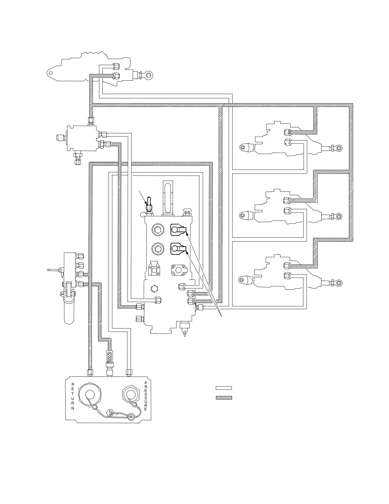
The primary hydraulic system (fig 2-63) provides hydraulic
2.77.4 Fluid Level Indicator. A fluid level indicator in
power to the primary side of all four flight control servocy-
the manifold housing allows visual inspection of the reser-
linders. Only the primary sides of these servo actuators
voir fluid level.
have electrohydraulic valves that allow the Flight Manage-
ment Computer (FMC) to affect the flight controls. Conse-
quently, failure of the primary hydraulic system will result
2.77.5 Primary System Pressure Sensing Switch. A
in the loss of FMC. The primary hydraulic equipment in-
pressure switch senses primary system pressure and in-
cludes a hydraulic pump, manifold, and servo actuators.
forms the pilot and CPG of a low fluid pressure condition
by generating a caution message on the UFD/EUFD.
2.76 PRIMARY HYDRAULIC PUMP
The primary hydraulic pump is mounted on the accessory
2.77.6 Pressure Transducer. A pressure transducer
drive case of the main transmission (left side). The pump
measures hydraulic pressure on the pressure side of the
is a constant pressure, variable displacement design,
manifold and transmits this value to the MPD.
driven by the transmission accessory gear train.
2.77 PRIMARY HYDRAULIC MANIFOLD
2.77.7 Pressure Transducer. A pressure transducer
measures hydraulic pressure on the pressure side of the
The primary manifold is installed on the left forward quad-
manifold and transmits this value to the MPD.
rant of the transmission deck. Its function is to store, filter,
and regulate the flow of hydraulic fluid as well as provide
analog pressure, dirty filter, and low level indications. The
2.78 UTILITY HYDRAULIC SYSTEM
manifold reservoir is pressurized on the return side by
IPAS air acting on the manifold reservoir piston. This pre-
vents pump inlet cavitation. Servicing crews introduce
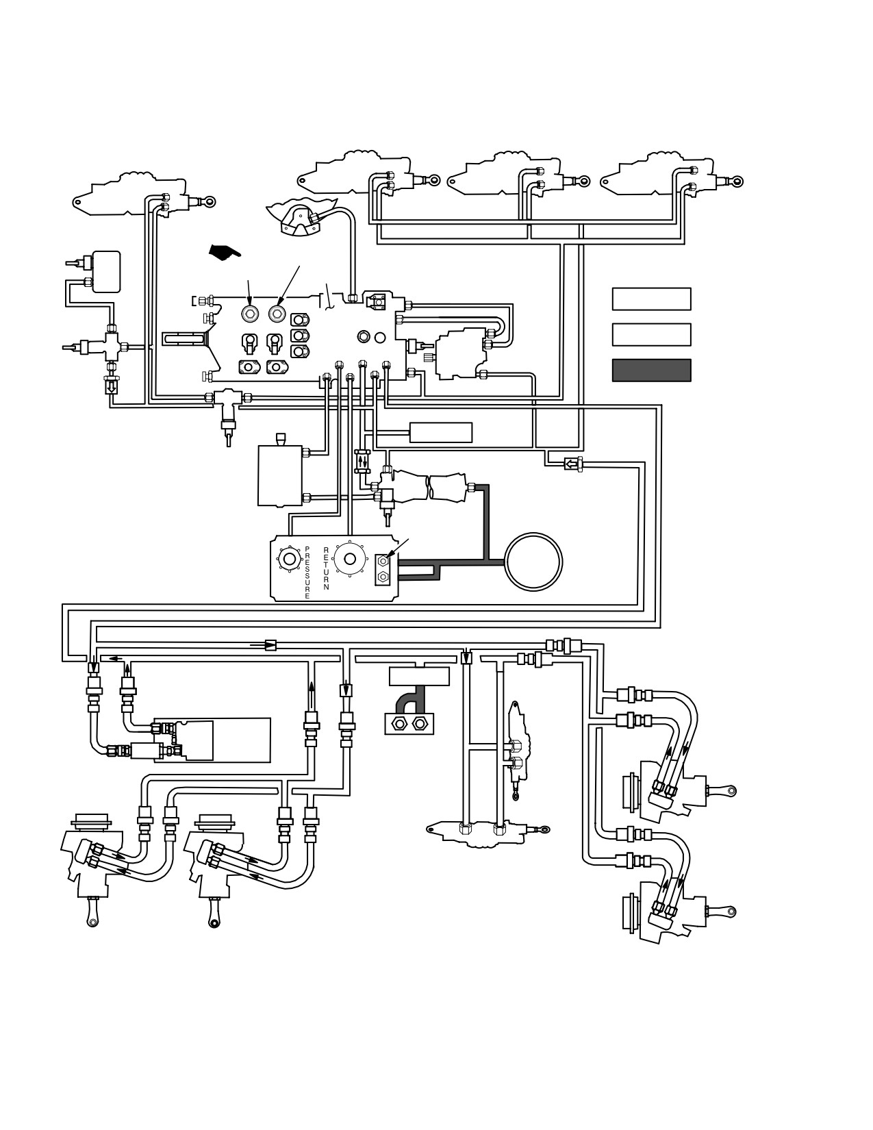
The utility hydraulic system (fig 2-64) provides hydraulic
fluid to the reservoir through the Ground Support Equip-
power to the utility side of all four flight control servocylind-
ment (GSE) connections or the hand pump. The primary
ers. This system also provides hydraulic power to the rotor
hydraulic system fluid capacity is 6 pt. The reservoir
brake, area weapon turret drive, ammunition handling
stores approximately 1 pt.
system, APU start motor, tail wheel unlock actuator, exter-
nal stores elevation actuators and emergency hydraulic
2.77.1 Air Bleed Valve. The air bleed valve is used to
system. Equipment includes a hydraulic pump, manifold,
deplete the pressurized air from the manifold reservoir for
and servocylinders. The pump is mounted on the acces-
system repair or service.
sory drive case of the main transmission (right side). The
significant difference in the primary and utility hydraulic is
2.77.2 Reservoir Low Level Indicating Switch. A res-
the manifold. Additional components in the system are the
ervoir low level indicating switch is activated by the man-
accumulator, rotor brake, and the utility hydraulic return
ifold reservoir piston. The UFD/EUFD displays the mini-
accumulator that dampens hydraulic pressure surges
mum operating level caution message.
caused by sudden actuation of the gun turret.
Use or disclosure of this information is subject to the restriction(s) on the title page of this document.
2-62
Change 2
TM 1-1520-251-10
DIRECTIONAL
SERVOCYLINDER
PRIMARY
PUMP
LATERAL
SERVOCYLINDER
IPAS
SIGHT
GAGE
COLLECTIVE
SERVOCYLINDER
FILTERS
HAND PUMP
LONGITUDINAL
SERVOCYLINDER
PRIMARY
MANIFOLD
FILTER INDICATORS
LEGEND
PRIMARY
PRESSURE
FLUID
RETURN
FILL
LBA0100
Figure 2-63. Primary Hydraulic System
Use or disclosure of this information is subject to the restriction(s) on the title page of this document.
2-63
TM 1-1520-251-10
LATERAL
COLLECTIVE
LONGITUDINAL
SERVOCYLINDER
SERVOCYLINDER
SERVOCYLINDER
DIRECTIONAL
SERVOCYLINDER
ÏÏ
ÏÏ
ÏÏ
ÏÏ
ÏÏ
Ï
Ï
ÏÏ
ÏÏ
Ï
Ï
Ï
ROTOR
ÏÏÏÏÏÏÏÏÏÏÏÏÏÏÏ
BRAKE
Ï
PRESS FILTER
Ï
TAIL
WHEEL
RTN FILTER
UTILITY
LEGEND
LOCK
Ï
MANIFOLD
Ï
TO PAS
Ï
ÏÏÏÏÏÏ
Ï
PRESSURE
SYSTEM
ROTOR
BRAKE
CONTROL
Ï
ÏÏÏÏÏÏ
ÏÏÏÏÏÏ
VALVE
Ï
GSE
ACC
AUX
ÏÏ
ÏÏÏÏÏÏRETURN
PRESS
PRESS
PRESS
UTILITY
START
GSE
PUMP
ÏÏ
RTN
RTN
RTN
Ï
NITROGEN
CHECK
ÏÏ
ÏÏÏÏ
ÏÏÏÏ
Ï
VALVE
ÏÏÏÏÏÏÏÏÏÏÏÏÏ
Ï Ï
SHUTOFF
ÏÏÏÏ
HAND PUMP
Ï Ï
VALVE
APU
ÏÏÏÏÏÏÏÏÏÏÏÏÏ
START
MOTOR
ÏÏÏ
ÏÏ
CHECK VALVE
ÏÏÏÏ
ÏÏ
Ï
UTILITY
ÏÏ
ACCUMULATOR
Ï
UTILITYÏÏGAGESURE
Ï
NITROGEN
GAS
Ï
RESERVOIR
Ï
ÏÏÏÏÏÏÏÏÏÏÏÏÏÏÏÏÏÏÏÏÏÏÏÏÏÏÏÏ
ÏÏ
ÏÏÏÏÏÏÏÏÏÏÏÏÏÏÏÏÏÏÏÏÏÏÏÏÏ
ÏÏÏÏÏÏÏÏÏÏÏÏÏÏÏÏÏÏÏ
RETURN
ÏÏÏÏÏÏ
ACCUMULATOR
ÏÏ
Ï
55 PSI
Ï
Ï
ÏÏ
ÏÏ
Ï
ÏÏÏÏÏ
CARRIER
CARRIER
ÏÏÏ
DRIVE
DRIVE
ÏÏ
Ï
ÏÏÏÏÏ
MOTOR
ASSEMBLY
LEFT
ÏÏ
ÏÏ
Ï
INBOARD
Ï
ÏÏÏÏÏÏÏÏÏ
Ï
TURRET
Ï
ÏÏ
RIGHT
ELEVATION
RIGHT
OUTBOARD
Ï
INBOARD
ÏÏ
Ï SERVOCYLINDER
ÏÏ
Ï
ÏÏ
Ï
Ï
ÏÏÏ
ÏÏÏÏÏ
TURRET
Ï Ï
AZIMUTH
SERVOCYLINDER
ÏÏÏ
ÏÏÏÏÏ
ÏÏÏÏÏ
Ï
LEFT
Ï
OUTBOARD
LBA−2542A
Figure 2-64. Utility Hydraulic System
Use or disclosure of this information is subject to the restriction(s) on the title page of this document.
2-64
Change 3
TM 1-1520-251-10
2.79 UTILITY HYDRAULIC MANIFOLD
utility hydraulic system. A pressure transducer measures
hydraulic pressure on the pressure side of the manifold
The utility manifold is installed on the aft main fuselage
and transmits this value for display on the MPD.
deck on the right side. It stores, filters, supplies, and regu-
lates the flow of utility hydraulic fluid. Demands on the util-
2.79.6 Rotor Brake Solenoid Valves. The solenoid
ity system are much greater than those on the primary
valves are controlled by the RTR BRK switch on the pilot
system, and the utility manifold is therefore larger. The
POWER lever quadrant (fig 2-42) adjacent to the POWER
utility manifold incorporates the utility accumulator hy-
levers. When this switch is positioned to BRK, utility sys-
draulic pressure transducer and rotor brake solenoids not
tem pressure is applied to stop the rotor brake disc on the
duplicated on the primary manifold.
main transmission. When positioned to LOCK, the brake
OFF solenoid valve traps pressure between the manifold
2.79.1 Low Level and Auxiliary Isolation Valves. The
and the utility system accumulator.
low level and auxiliary isolation valves permit hydraulic
fluid to flow to external stores, ammo carrier drive, and
2.79.7 Reservoir Low Level Indicating Switch. A res-
area weapon turret. If reservoir fluid level decreases sig-
ervoir low level indicating switch is activated by the man-
nificantly, the reservoir piston, driven by IPAS air, closes
ifold reservoir piston. A minimum operating level caution
the low level valve. The auxiliary isolation valve, which
message is presented on the UFD/EUFD sent from the
normally requires two sources of pressure to permit fluid
low level indicating switch.
flow, then closes and denies hydraulic power to the area
weapon turret, external stores actuator, and ammo carrier
2.79.8 Manifold Pressure and Return Filters. Filters
drive.
on both manifold pressure and return sides have mechan-
ical dirty filter indicators for visual inspection. These indi-
cators operate on differential pressure. Only the return fil-
2.79.2 Shutoff Valve. A shutoff valve in the pressure
ter has bypass valve provision. In addition to the
line to the directional servo and tail wheel unlock actuator
mechanical/visual indicators both filters contain electrical
is actuated by the low level switch in the utility system res-
switches that provide signals to generate a caution mes-
ervoir. The utility side of the directional servo actuator and
sage on the UFD/EUFD
the tail wheel unlock actuator become inoperative if a low
utility system fluid level is sensed.
2.79.9 Fluid Level Indicator. A fluid level indicator in
the manifold housing allows visual inspection of the reser-
2.79.3 Accumulator Isolation Valve. The accumulator
voir fluid level.
isolation valve normally isolates accumulator pressure
from the rest of the utility system but allows system flow
2.79.10 Utility System Pressure Sensing Switch. A
from the pump to pass through a portion of the valve to the
pressure switch senses utility system pressure and in-
utility side of the tandem servocylinders.
forms the pilot and CPG of a low fluid pressure condition
by generating the caution message on the UFD/EUFD.
2.79.4 Override Solenoid. An override solenoid, de-
energized to the closed position, permits crew manage-
2.80 UTILITY HYDRAULIC ACCUMULATOR
ment of accumulator reserve pressure. Upon activation of
the EMERG HYD pushbutton, the override solenoid valve
NOTE
energizes open and accumulator fluid passes to the accu-
mulator isolation valve via emergency routing. In this
The accumulator should be checked on pre-
case, another portion of the accumulator isolation valve
flight and thru-flight inspections for a mini-
permits accumulator fluid to flow to the utility side of the
mum of 2600 psi prior to APU start.
servocylinders.
The accumulator stores hydraulic fluid at 3000 psi. The
2.79.5 Pressure Transducer. An accumulator hydrau-
accumulator provides damping for fluid pressure
lic pressure transducer in the manifold provides the pilot
changes, hydraulic power for rotor brake application, APU
with a continuous indication of accumulator pressure on
starting, and emergency flight control operation. The start
the accumulator hydraulic pressure indicator. During nor-
valve opens when the APU ON button is pressed to ON
mal operation, the indicated pressure is the same as the
and closes automatically at 60% APU speed.
Use or disclosure of this information is subject to the restriction(s) on the title page of this document.
Change 3
2-65
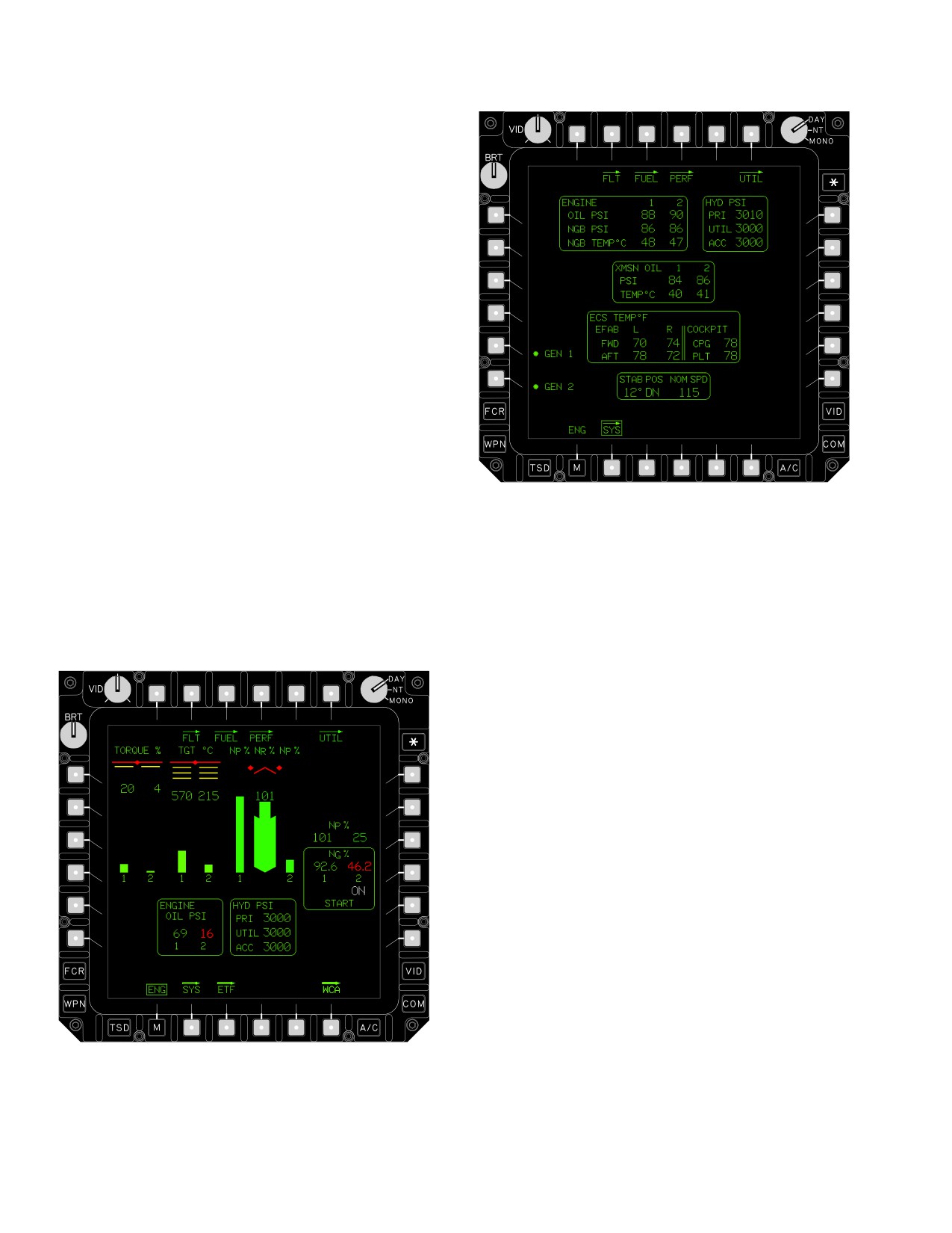
TM 1-1520-251-10
2.81 UTILITY HYDRAULIC RETURN ACCUMULATOR
The utility hydraulic return accumulator stores hydraulic
fluid at 55 psi. The accumulator dampens hydraulic pres-
sure surges caused by sudden actuation of the gun turret.
2.82 HYDRAULIC SYSTEM HAND PUMP
A hand pump is installed, next to the primary system GSE
panel, on the right side of the aircraft. The pump provides
one method of charging fluid pressure in the utility accu-
mulator as well as access for the ground crew to fill the
primary and utility reservoirs. The control lever may be
moved to any of three positions. This opens one of three
check valves to the accumulator or to either reservoir.
2.83 HYDRAULIC SYSTEM CONTROLS AND
DISPLAYS
LBA2540A
Operation of the hydraulic system is automatic except in
emergency situations, tail wheel locking/unlocking, and
rotor brake activation. Hydraulic system indications are
displayed on the ENG page ground format (fig. 2-65) and
Figure
2-66.
SYS Page
SYS page (fig 2-66).
2.83.1 ENG Page Ground Format.. See Section III for
descriptions of ENG page ground indications.
2.83.2
SYS Page. The following hydraulic pressures
(HYD PSI); primary (PRI), utility (UTIL) and accumulator
(ACC) are indicated on the ENG SYS page:
NOTE
The following descriptions of SYS page hy-
draulic system indications give ranges of
those displays. Refer to Chapter 5 for sys-
tem limits and restrictions.
PRI/UTIL/ACC PSI
0 to 6000
displayed in increments of 10 psi.
3410 - 6000
YELLOW ≥5 seconds RED w/box
3310 - 3400
YELLOW ≥5 minutes RED w/box
1260 - 6000
GREEN
0-1250
RED w/box
2.83.3 Emergency Hydraulics. An override solenoid
LBA3000
valve, normally de-energized closed, permits crew man-
agement of accumulator reserve pressure. Upon activa-
tion of the EMER HYD ON button on the EMERGENCY
Figure
2-65.
ENG Page Ground Format
panel (fig 2-67), the button will become
Use or disclosure of this information is subject to the restriction(s) on the title page of this document.
2-66
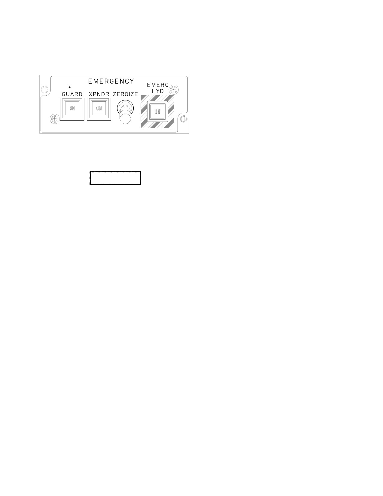
TM 1-1520-251-10
illuminated, the valve energizes open and accumulator
from being locked when the power levers are in any posi-
fluid passes via emergency routing to the utility side of the
tion except IDLEor OFFWhen the switch is set atBRK so-
servo actuators.
lenoid valves in the utility hydraulic manifold operate and
applies 337 psig to actuate the the brake. When rotors are
stopped, the switch may be set to LOCKwhich causes the
solenoid valves in the manifold to de-energize and all
available utility hydraulic system or accumulator pressure
to be applied to the brake. With the switch atOFF, the only
hydraulic pressure to the brake is 30 psig from the pres-
surized air system which, when operating, pressurizes the
return side of the utility hydraulic system. If helicopter
power is lost, the rotor brake, if previously set at LOCK re-
mains locked as long as accumulator pressure is avail-
LBA0021A
able.
Figure 2-67. EMERG HYD Pushbutton
2.83.5 Tail Wheel Lock. Utility hydraulic pressure is
used by the tail wheel lock actuator to unlock the tail
wheel. The tail wheel can be locked or unlocked from ei-
CAUTION
ther crew station via theTAIL WHEEL panel or collective
grip switch (refer to Section I). The tail wheel can also be
Do not place theRTR BRK switch in LOCK
locked or unlocked by ground crew using a handle pro-
position with rotors turning.
vided on the locking device.
NOTE
2.84 INTEGRATED PRESSURIZED AIR SYSTEM
When engaging rotor lock, pause in the
(IPAS)
BRK position until the RTR BRK advisory
message is displayed prior to placing the
Pneumatic power for the IPAS (fig 2-68) is generated by
switch in the LOCK position. The POWER
dual engine bleed air, APU or AGPU air. The IPAS pres-
levers will not advance past the ground idle
detent with the rotor brake switch in the
surizes, regulates, and distributes air to the following:
LOCK position.
• Air turbine starter
2.83.4 Rotor Brake. The rotor brake is a disc brake
• Fuel boost and transfer pumps
mounted at the aft end of the main transmission. The rotor
• External fuel tanks
brake reduces turnaround time for aircraft loading and
servicing and prevents windmilling of the rotor system
• Hydraulic reservoirs
during gusty wind conditions. TheRTR BRK switch on the
pilotPOWERlever quadrant has three modes:OFF, BRK,
• Engine inlet anti-ice
and LOCK. The BRK mode reduces time required to stop
• Ice detect probe aspirator
the main rotor system after engine shutdown. TheLOCK-
mode is used to prevent windmilling in strong winds and
• Nitrogen inerting unit
for locked rotor dual engine starts. When both engines are
• Engine firewall/cooling
at idle and the switch set atLOCK (full 3000 psig utility hy-
draulic system pressure), the brake prevents the drive
• Utility receptacle
train and power turbine from being driven by the gas tur-
bine. A system of three interlocks prevents the rotor brake
• Environmental Control System (ECS)
Use or disclosure of this information is subject to the restriction(s) on the title page of this document.
2-67
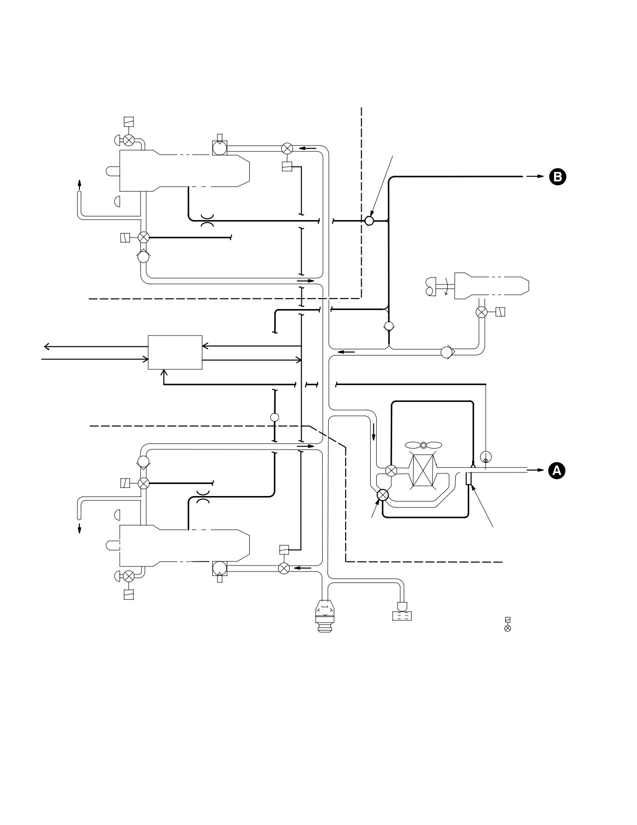
TM 1-1520-251-10
FIREWALL
ENG INLET
AIR TURBINE
ANTI−ICE
STARTER (ATS)
ATS PRESSURE
SOV
REGULATOR SOV
HIGH PRESSURE
CHECK VALVE
TO ENG COOLING
ENGINE 2
DOOR ACTUATOR
(RH)
HP
LP
LP
RESTRICTOR
VENTURI
ENG BLEED
FLOW SHARE
PRESSURE
REGULATOR
SENSE LINE
ACCESSORY
SOV
ENG BLEED
GEARBOX
AIR CHECK
INTERFACE
VALVE
APU
FIREWALL
HYDRAULIC
APU
APU LOAD
RESERVOIR
CREWSTATION
CHECK
CONTROL
CHECK
CAUTION INDICATION
ATS PRSOV POSITION
VALVE
VALVE
SYSTEM
VALVE
ENGINE Ng
PRESSURE
ATS PRSOV CLOSE
PROCESSOR
OVERTEMP SIGNAL
HIGH PRESSURE
ENGINE
CHECK VALVE
BLEED AIR
FIREWALL
PRECOOLER
AND FAN
BLEED AIR
OVERTEMP
ENG BLEED
SWITCH
ENG BLEED
AIR CHECK
PRESSURE
VALVE
REGULATOR
FLOW SHARE
SOV
SENSE LINE
RESTRICTOR
LP
VENTURI
PRECOOLER
LP
BYPASS
PRECOOLER BYPASS
HP
TO ENG COOLING
ENGINE 1
CONTROL
TEMPERATURE
DOOR ACTUATOR
VALVE
THERMOSTAT
(LH)
FIREWALL
ATS PRESSURE
ENG INLET
AIR TURBINE
REGULATOR
ANTI−ICE
STARTER (ATS)
SOV
SOV
NOTES:
UTILITY
1. SYMBOL
DENOTES
RECEPTACLE
28 Vdc SOLENOID
GROUND CART
ACTUATED VALVE.
CONNECTION
LBA02911
Figure 2-68. Integrated Pressurized Air System (Sheet 1 of 2)
Use or disclosure of this information is subject to the restriction(s) on the title page of this document.
2-68
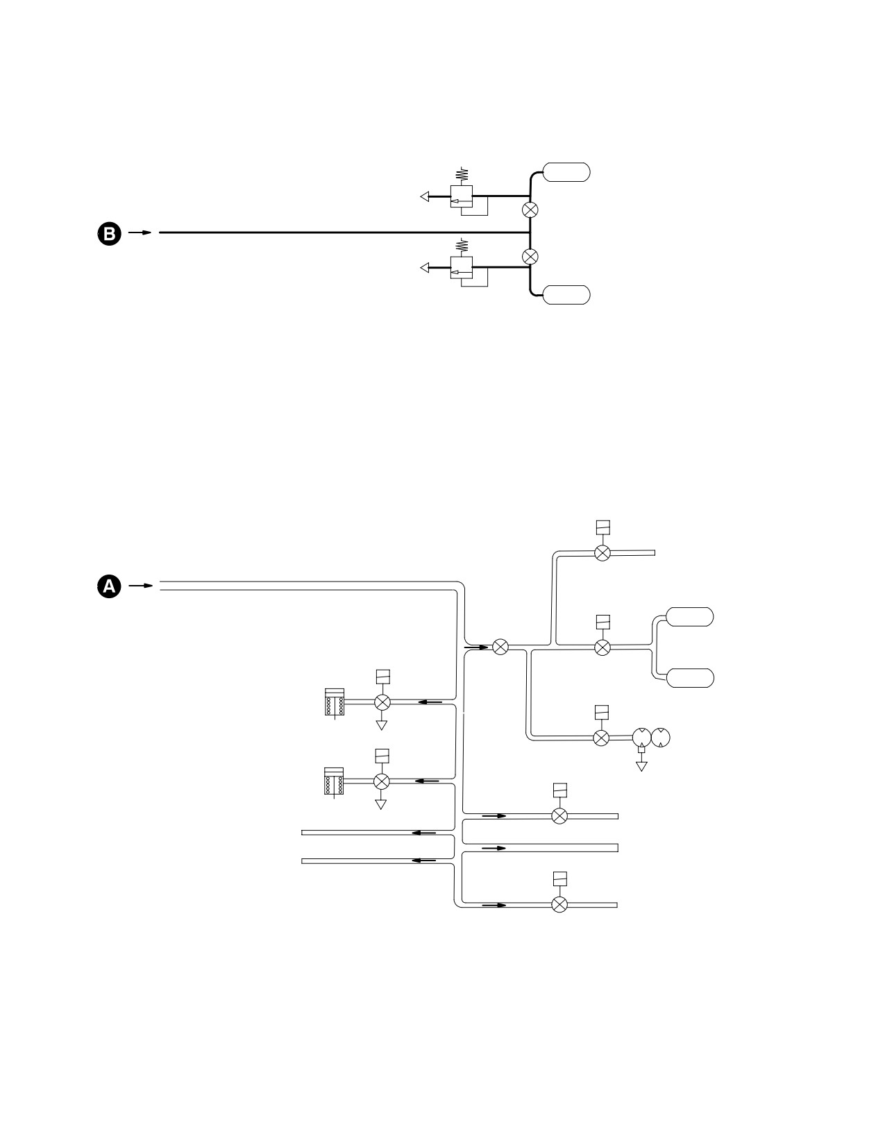
TM 1-1520-251-10
HYDRAULIC RESERVOIR
PRESSURE RELIEF VALVE
PRIMARY
HYDRAULIC
RESERVOIR
HYDRAULIC RESERVOIR
PRESSURE REGULATOR
HYDRAULIC RESERVOIR
PRESSURE REGULATOR
UTILITY
HYDRAULIC
HYDRAULIC RESERVOIR
RESERVOIR
PRESSURE RELIEF VALVE
FUEL TRANSFER
PUMP SOV
TO FUEL
TRANSFER
PUMP
EXTERNAL FUEL TANK
PRESSURIZATION SOV
FUEL SYSTEM
PRESSURE
REGULATOR
EXTERNAL
LOUVER
FUEL TANKS
ACTUATOR
LOUVER
CONTROL
ACTUATOR
VALVE
FUEL BOOST
PUMP SOV
LOUVER
LOUVER
ACTUATOR
ACTUATOR
CONTROL
FUEL BOOST
VALVE
PUMP
CABIN DEFOG SOV
TO DEFOG
TO NITROGEN
SYSTEM
INERTING UNIT
TO ECS
TO ECS AIR PARTICLE
ICE DETECTOR PROBE SOV
SEPARATOR
TO ICE DETECTOR
PROB
LBA02912
Figure 2-68. Integrated Pressurized Air System (Sheet 2 of 2)
Use or disclosure of this information is subject to the restriction(s) on the title page of this document.
2-69
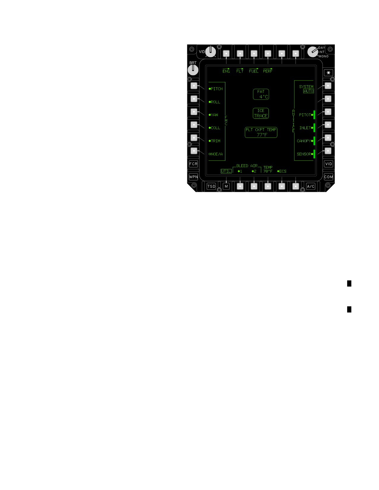
TM 1-1520-251-10
2.84.1 Dual Engine Bleed Air. The IPAS subsystem
primary pneumatic power source is dual engine bleed air.
Bleed air is provided by both engines during normal op-
eration.
2.84.2
Single Engine Bleed Air. The secondary
source of pneumatic power for the IPAS is single main en-
gine bleed air.
2.84.3 Power Up. During aircraft power up, APU bleed
air is the pressurized air source and is used to start main
engines. External air from an AGPU or another aircraft
may be used to start engines via the external air recep-
tacle. Each engine has a low and high pressure bleed air
port. The high pressure port is used exclusively to pres-
surize the hydraulic reservoirs and the low pressure port
supports the remaining functions. Low pressure flow and
pressure is controlled by the engine bleed pressure regu-
lator and shutoff valve. High pressure flow and pressure is
controlled by a restrictor and a regulator.
2.84.4 IPAS Contro. Control of IPAS is an integrated
LBA - 2083
function provided by system processors, display proces-
Figure 2-69. A/C UTIL Page (Pilot)
sors, and the Electrical Power Management System
(EPMS). The A/C UTIL page (fig 2-69) provides BLEED
2.84.5 PAS Cautions. Crewmembers are provided the
AIR 1 and 2ON/OFF pushbuttons.
following IPAS advisory messages via the Warning/Cau-
tion/Advisory system:
a. Engine Bleed Air Fail. This advisory message
occurs when engine 1 and/or engine 2 primary shutoff
valve is in the commanded position and the system pro-
cessor commands the engine 1 and/or engine 2 bleed air
shutoff valve open or closed and it does not move.
b. Engine Bleed Air Overtemperture. When the
system processor receives a bleed air overtemperature
signal, it will send a caution message to the UFD/EUFD.
Use or disclosure of this information is subject to the restriction(s) on the title page of this document.
2-70
Change 2
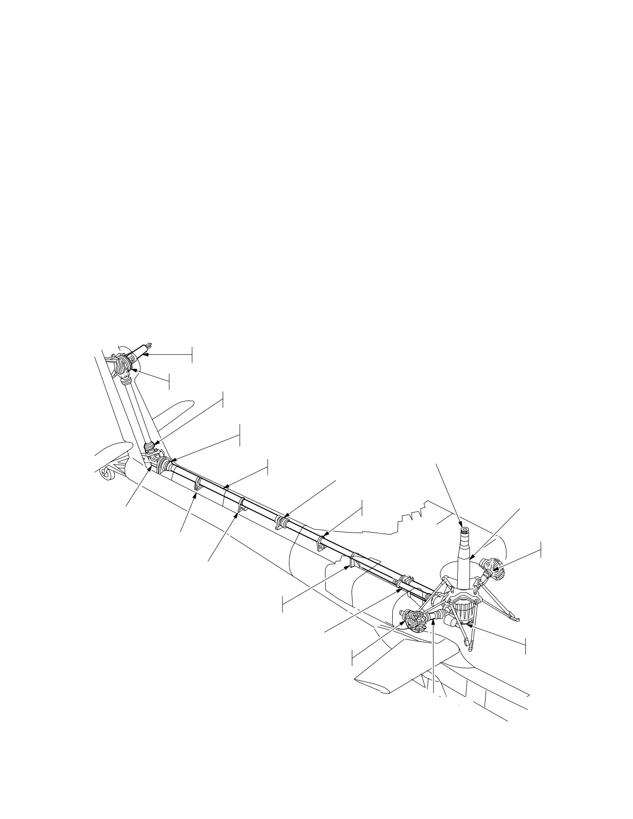
TM 1-1520-251-10
Section VII. DRIVE TRAIN SYSTEM
2.85 INTRODUCTION
• Tail rotor gearbox
The drive train (fig 2-70) transmits engine power to the ro-
tors and to accessories mounted on the transmission. The
2.86 MAIN ROTOR DRIVE SYSTEM
drive train includes the following:
• Two engine nose gearboxes
2.86.1
Engine Nose Gearboxes. One engine nose
gearbox is mounted on the front of each engine. They re-
• Two input shafts
duce drive shaft speed and change the angle of the drive.
• APU drive shaft and couplings
Both nose gearboxes have self contained pressurized oil
systems with provisions to ensure limited operation if a to-
• Couplings and input clutch to the main transmis-
tal loss of pressurized lubrication occurs. The input drive
sion
shafts have flexible couplings that require no lubrication.
• Main transmission
Sensors and detectors monitor the nose gearboxes and
provide information to crewmembers about oil tempera-
• Main rotor drive shaft
ture, oil pressure, and the presence of metal chips. High
• Tail rotor drive shafts
oil temperature, low oil pressure, and presence of metallic
chips in the gearbox cause cautions to be annunciated in
Intermediate gearbox
the crew stations.
TAIL ROTOR
STATIC MAST
TAIL ROTOR
GEARBOX
FLEXIBLE COUPLING
(TYPICAL)
TAIL ROTOR AND
INTERMEDIATE BEARBOX
COOLING FAN
MAIN ROTOR
DRIVE SHAFT
TAIL ROTOR
DRIVE SHAFT
HANGER BEARING
STATIC MAST
ANTIFLAIL
INTERMEDIATE
SLEEVE
GEARBOX
ANTI−FLAIL
SLEEVE
COOLING
FANS (2)
DRIVE SHAFT
DAMPER
DRIVE SHAFT
DAMPER
APU DRIVE SHAFT
MAIN
TRANSMISSION
NOSE
GEARBOX (2)
INPUT DRIVE SHAFTS (2)
LBA0115
Figure 2-70. Drive Train
Use or disclosure of this information is subject to the restriction(s) on the title page of this document.
2-71
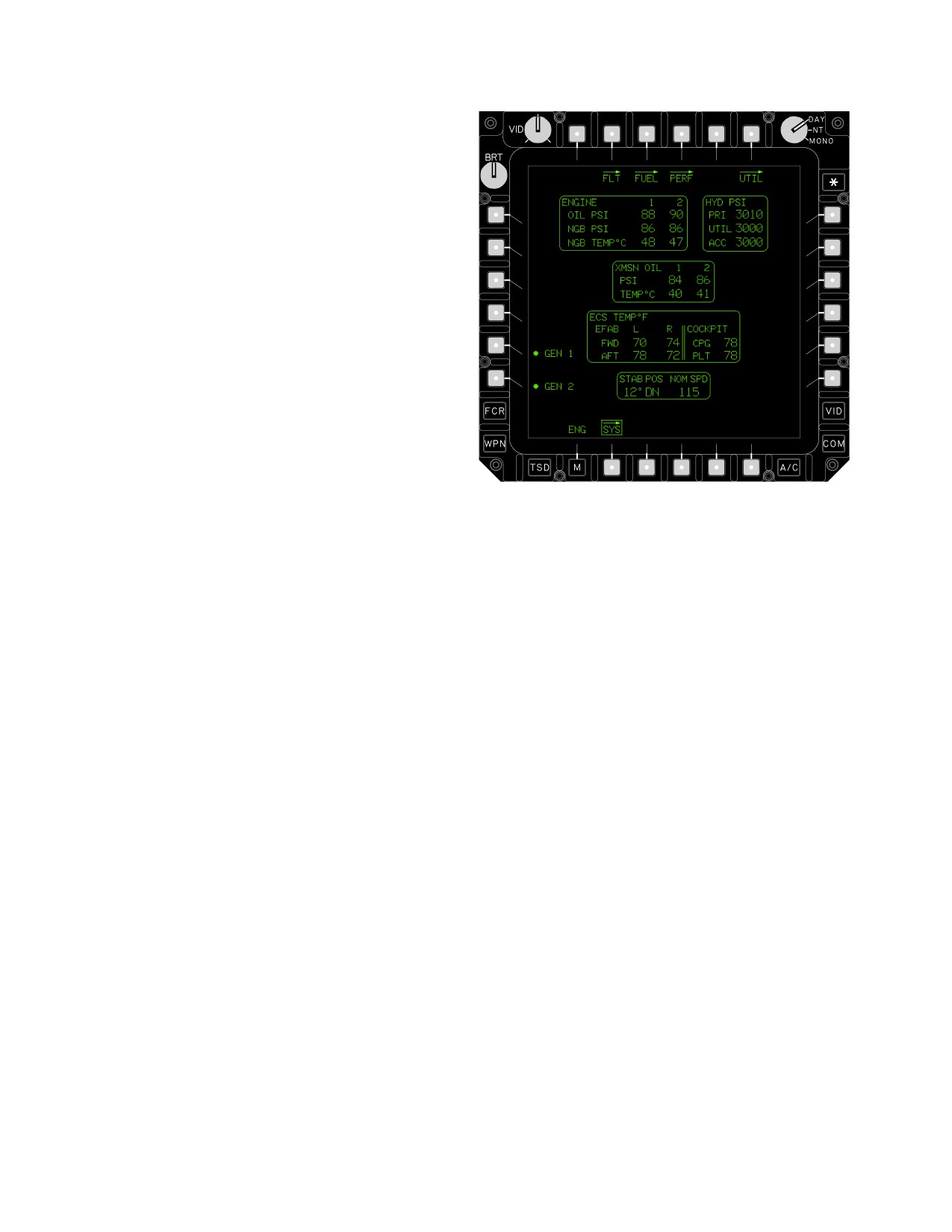
TM 1-1520-251-10
2.86.2 Main Transmission. The main transmission is
mounted below the main rotor static mast base which al-
lows its removal without removing the upper controls,
mast or hub. The main transmission combines the two en-
gine nose gearbox inputs, reduces output RPM, and pro-
vides drive to the main rotor, tail rotor, accessories, and
rotor brake disc. Sensors in the transmission monitor
conditions and provide crewstation caution messages.
a. Main Rotor Drive Shaft. The main rotor drive
shaft is designed to carry torque loads only. The rotor hub
is on a static mast which carries vertical or bending loads.
The drive shaft rotates inside the static mast.
b. Reduction Gearing. The main transmission has
a three stage primary reduction gearing with two engine
inputs, main rotor, and tail rotor power output. An over run-
ning clutch provides APU drive to the accessory section of
the transmission when the rotor is stopped.
LBA2610A
c. Accessory Gearbox. The accessory gearbox is
driven by the APU drive shaft or engine drive shafts and
Figure 2-71. SYS Page
provides shaft power to the main generators and the hy-
draulic pumps while the rotor is stationary or rotating. The
oil pressure in the gearbox is monitored by the accessory
NGB1 OR 2 OIL PRESSURE (PSI)
oil pressure switch. Reduction gearing and drive shaft
coupling is provided.
0 to 100 psi Resolution 1 psi.
30 - 100 psi Normal operation (GREEN)
d. Main Transmission Lubrication. The main
30 psi Minimum (<30 RED w/box)
transmission has two independent oil systems. Each sys-
tem has its own sump, pump, filter, and heat exchanger.
Oil level sight gages are located in the transmission hous-
NGB1 OR 2 OIL TEMPERATURE (°C)
ing at each oil sump. These systems are not totally inde-
- 32 to 149
Resolution 1_
pendent in the usual sense because during normal opera-
134
Maximum (>134 RED w/box)
tion, the oil mixes. If oil loss occurs in either sump or in
either heat exchanger, the diverter (float) valve will seal off
0-134
Normal operation (<134 GREEN)
that sump to prevent a total loss of oil.
2.87.2 Transmission Oil Status Indications. The fol-
2.87 DRIVE TRAIN CONTROLS AND DISPLAYS
lowing main transmission oil status indications are dis-
played on the SYS page:
Engine nose gearbox and main transmission systems in-
dications are displayed on the SYS page (fig 2-71).
XMSN 1 OR 2 OIL PRESSURE (PSI)
0 to 100 psi Resolution 1 psi
NOTE
30 - 100 psi Normal operation (GREEN)
The following descriptions of SYS page en-
30 psi Minimum (<30 RED w/box)
gine(s) NGB and main transmission indica-
tions give ranges of those displays. Refer to
Chapter 5 for system limits and restrictions.
XMSN 1 OR 2 OIL TEMPERATURE (°C)
- 32 to 149
Resolution 1_
2.87.1 Engine NGB Oil Status Indications. The fol-
134
Maximum (>134 RED w/box)
lowing engine oil status indications are displayed on the
- 32 - 134
Normal operation (<134 GREEN)
SYS page:
Use or disclosure of this information is subject to the restriction(s) on the title page of this document.
2-72
TM 1-1520-251-10
2.88 TAIL ROTOR DRIVE SYSTEM
2.88.2 Intermediate Gearbox. The intermediate gear-
box reduces RPM and changes the angle of drive to the
tail rotor. The intermediate gearbox is a grease lubricated
The tail rotor drive system consists of the tail rotor drive
sealed unit. Four thermistors monitor temperature and an
shafting, couplings, hanger bearing, dampers, anti-flail
accelerometer measures vibration to provide crewmem-
assemblies, and intermediate and tail rotor gearboxes.
bers with UFD/EUFD caution messages.
2.88.1 Tail Rotor Drive Shaft. There are four tail rotor
drive shaft sections. Three tail rotor drive shaft sections
CAUTION
lead from the transmission to the intermediate gearbox.
Two are of equal length. The fourth section is installed on
Prolonged OGE hover (20-30 minutes)
the vertical stabilizer between the intermediate and tail ro-
with outside air temperature above 755 F
tor gearboxes. Hanger bearings support the longer shafts.
(245 C) may cause the tailrotor gearbox
The two equal length shafts incorporate friction dampers
to overheat.
and anti-flail assemblies. Flexible couplings, attached to
the shaft ends, are capable of accommodating shaft mis-
2.88.3
Tail Rotor Gearbox. The tail rotor gearbox,
alignments throughout the power range.
mounted on the vertical stabilizer, reduces the output rpm
and changes the angle of drive. The tail rotor output shaft
passes through the gearbox static mast. All tail rotor loads
CAUTION
are transmitted to the static mast. The output shaft trans-
mits only torque to the tail rotor. Lubrication of this gear-
Prolonged OGE hover (20-30 minutes)
box is identical to that of the intermediate gearbox. As with
with outside air temperature above 755 F
the intermediate gearbox, four thermistors monitor tem-
(245 C) may cause the intermediate gear-
perature and an accelerometer measures vibration to pro-
box to overheat.
vide crewmembers with UFD/EUFD caution messages.
Use or disclosure of this information is subject to the restriction(s) on the title page of this document.
Change 2
2-73
TM 1-1520-251-10
Section VIII. ROTORS
2.89 ROTOR SYSTEM
move horizontally. The pin goes through the “V” portion of
each strap within the pitch housing.
The rotor system (fig 2-72) consists of a four bladed, fully
articulated main rotor and a four bladed tail rotor assem-
2.90.3 Damper Assembly. Two damper assemblies con-
bly with two teetering rotor hubs.
trol lead-lag movement of each main rotor blade. Each
damper attaches outboard to a link lug and inboard to a
2.90 MAIN ROTOR ASSEMBLY
trunnion at the pitch housing. The dampers contain elas-
tomeric elements that distort to allow the blade to lead or
The main rotor has four removable blades. The rotor head
lag.
allows the four blades to flap, feather, lead, or lag inde-
pendently. The head consists of a hub assembly, pitch
2.90.4 Main Rotor Blades. The outboard tip is swept
housings, rotor dampers, and lead-lag links. The main ro-
aft 20° and tapers to a thinner section. Tip weights are in-
tor is controlled by the cyclic and collective control sticks
stalled in the blades. Each blade is secured to its lead-lag
through a swashplate mounted about the static mast. This
link by two blade attachment pins. These pins can be re-
arrangement allows the static mast, rather than the main
moved without the use of tools. Sets of five doublers are
rotor drive shaft, to assume all flight loads. The hub is
located on the upper and lower surfaces of the blade at
splined to the main rotor drive shaft by a drive plate adapt-
the blade root.
er bolted to the hub. The hub is secured to the static mast
by a large locknut secured with multiple bolts. The hub
2.91 TAIL ROTOR ASSEMBLY
houses two sets of grease lubricated, sealed roller bear-
ings that transfer hub loads to the static mast. Mechanical
droop stops limit blade droop. When blade droop occurs,
The tail rotor system is of semi-rigid, teetering design. Two
a striker plate on the pitch housing contacts a roller. The
pairs of blades, each pair fastened to its own delta hinged
roller presses a plunger against a droop stop ring on the
hub, provide anti-torque action and directional control. A
lower portion of the hub.
titanium fork houses four elastomeric teetering bearings
and drives the rotating swashplate through an attached
2.90.1 Pitch Housing. The pitch housing permits blade
scissors assembly. The tail rotor assembly is splined to,
pitch changes in response to flight control movements
and driven by, the tail rotor gearbox drive shaft which
transmitted through the swashplate. This is made possi-
passes through a static mast. Blade pitch changes are
ble within the four pitch housings by “V” shaped stainless
made when directional control inputs cause the non-rotat-
steel strap assemblies that twist and flap to permit blade
ing swashplate to act upon the rotating swashplate. One
feathering, flapping, and carry the centrifugal force load.
pitch link for each blade, attached to the rotating swash-
Cyclic and collective stick inputs are transmitted to the
plate and pitch horn, causes blade movement about two
pitch housing horns by pitch links attached to the swash-
pitch change bearings in the blade root. Centrifugal forces
plate. Feather bearings are installed inboard on the pitch
are carried by strap assemblies attached outboard to the
housing to allow vertical and horizontal loads to be trans-
blade root and inboard at the hub center. An elastomeric
ferred from pitch housing to the hub. Centrifugal loads are
bearing assembly positions the hub and strap pack in the
transmitted by each strap assembly to the hub.
tail rotor fork. Each blade has one stainless steel spar and
two aluminum spars. Doublers, adhesive, and rivets at-
2.90.2 Lead Lag Links. Lead-lag links are connected
tach the blade to the blade root. Brackets on the root fitting
to the outboard end of each pitch housing and are secured
hold chord-wise balance weights. Span-wise balance
in place by a pin and two bearings allowing the links to
weights are installed in blade tip caps.
Use or disclosure of this information is subject to the restriction(s) on the title page of this document.
2-74
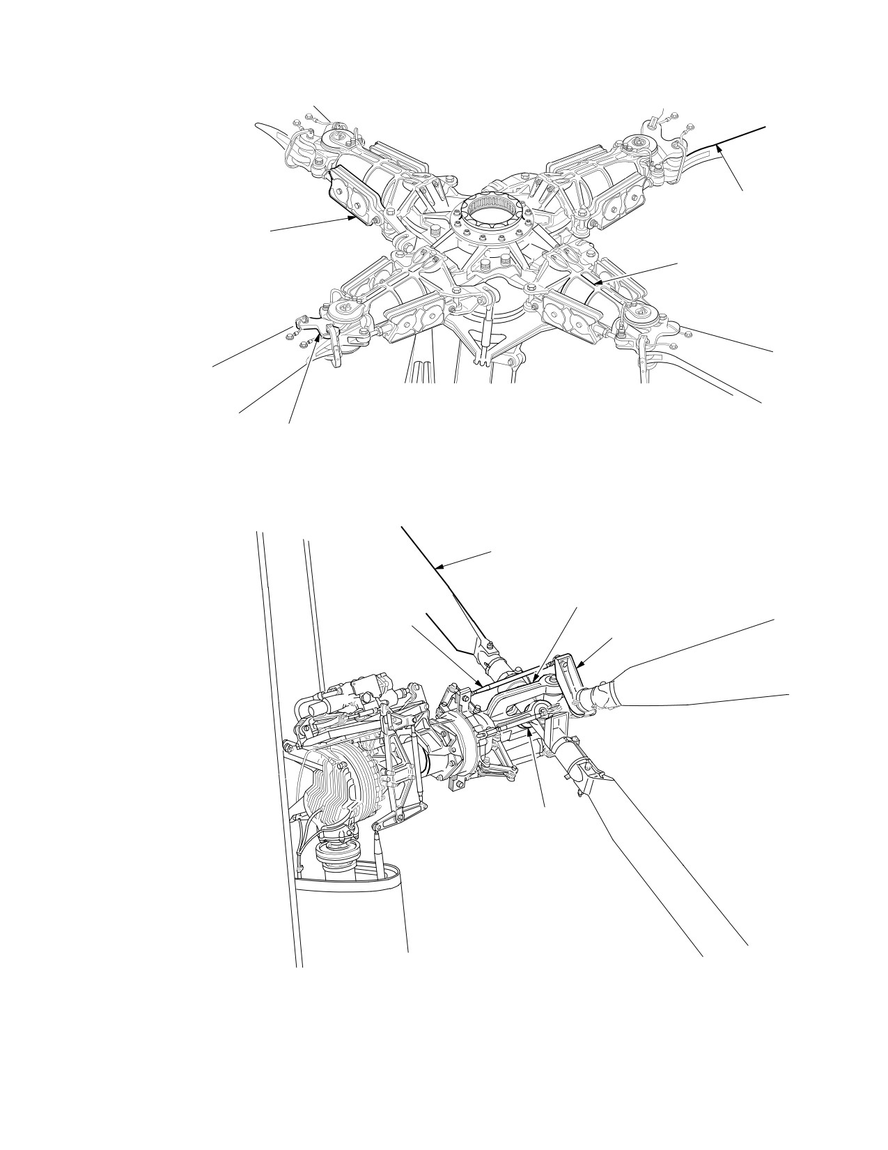
TM 1-1520-251-10
MAIN ROTOR BLADE
DAMPER ASSEMBLY
PITCH HOUSING
LEADLAG LINK
MAIN ROTOR ASSEMBLY
TAIL ROTOR BLADE
FORK
PITCH LINK
PITCH HORN
TAIL ROTOR
HEAD ASSEMBLY
TAIL ROTOR ASSEMBLY
LBA1877
Figure 2-72. Rotor System
Use or disclosure of this information is subject to the restriction(s) on the title page of this document.
2-75
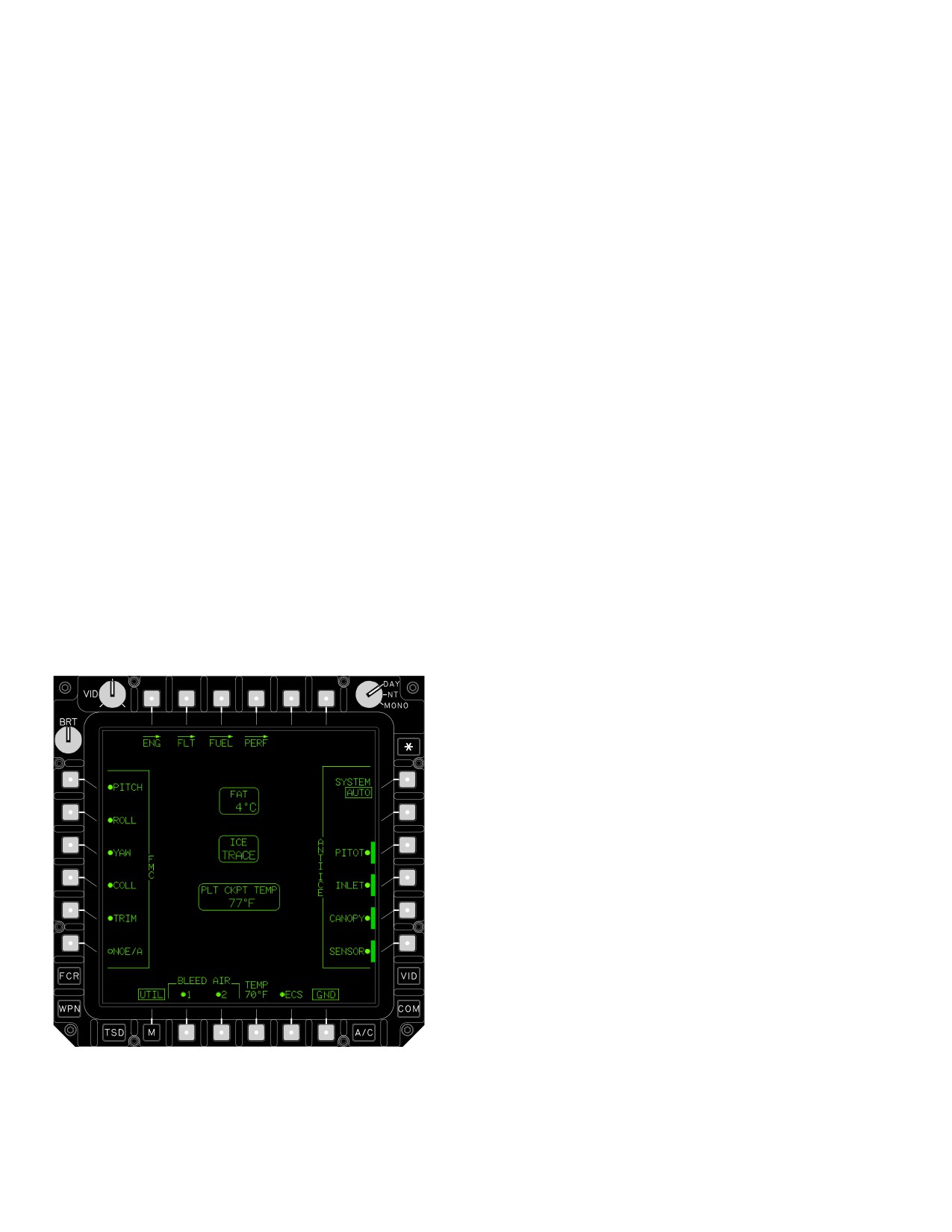
TM 1-1520-251-10
Section IX. UTILITY SYSTEMS
2.92 ANTI-ICE SYSTEM
a. AUTO Mode. When in the AUTO mode, ANTI-
ICE system buttons are not selectable when an icing con-
ditions is detected. The buttons are selectable in this
The anti-ice protection systems provides crewmembers
mode when no icing condition is detected. The SP uses
with automatic and manual means to prevent ice accu-
the ice status signal from the ice detector signal processor
mulation (anti-ice). Anti-ice subsystems are installed in
and FAT status from the FMC to determine when to acti-
the airspeed sensors, engine inlets, engine nose gear-
vate the anti-ice systems. Once activated, anti-ice sys-
boxes, canopy, sensor shrouds and windows of TADS/
tems are not automatically set to off; the systems must be
PNVS.
manually selected to off.
2.92.1 Ice Detect Probe. The Ice Detect Probe aspira-
tor will become active when the Free Air Temperature
b. MANUAL Mode. When in MANUAL mode, the
(FAT) decreases to 5° C or less. When the ice detect
ANTI-ICE system buttons are selectable. When entering
probe senses ice, it sends a discrete ice detect signal and
the MANUAL mode, any anti-ice system that is currently
an analog icing rate signal to the SP. In the AUTO mode,
ON (activated in the AUTO mode), will remain in an ON
the SP commands all anti-icing functions to an ON state
state.
when the icing rate signal indicates an icing condition. The
probe will be deactivated when the FAT increases to 7° C
c. FAT Status Window. The current FAT value is
or higher. The SP will not command the anti - icing func-
displayed in the FAT status window. The range value of
tions to OFF. In MANUAL control, the anti-ice system op-
FAT is from -50° C to +50° C.
eration is independent of icing conditions.
2.92.2 Anti-Ice System Controls. The A/C UTIL page
d. ICE Status Window. The current ICE status is
(fig 2-73) ANTI-ICE SYSTEM button toggles the system
displayed in the ICE status window. The state of the ICE
between MANUAL and AUTO modes.
status is displayed in conditions of TRACE (GREEN),
LIGHT (WHITE), MODER (YELLOW), or SEVERE
(RED).
2.92.3 Airspeed Sensors Anti-Ice. The airspeed sen-
sors anti-ice system prevents formation of ice that could
cause false indications from the pitot tubes and Air Data
Sensors. When PITOT is selected, power is applied to
heat the pitot tubes and ADS, which prevents ice forma-
tion on the tubes and sensors.
2.92.4 Engine INLET Anti-Ice System. The engine
anti-ice system includes the engine, engine inlet fairings,
and nose gearbox fairings. Engine fifth stage bleed air is
used to heat the swirl vanes, nose splitter, and engine inlet
guide vanes on each engine. The nose gearbox fairing is
electrically heated to prevent ice from forming on the sen-
sors.
2.92.5 CANOPY Anti-Ice. Canopy windshield anti-ice
is incorporated into the pilot and CPG middle forward
LBA0651A
looking windshields. Heating elements and sensors are
embedded into the windshield laminates. When CANOPY
is selected, heat produced by the elements prevents ice
Figure
2-73.
A/C UTIL Page (Pilot)
formation on the windshields.
Use or disclosure of this information is subject to the restriction(s) on the title page of this document.
2-76
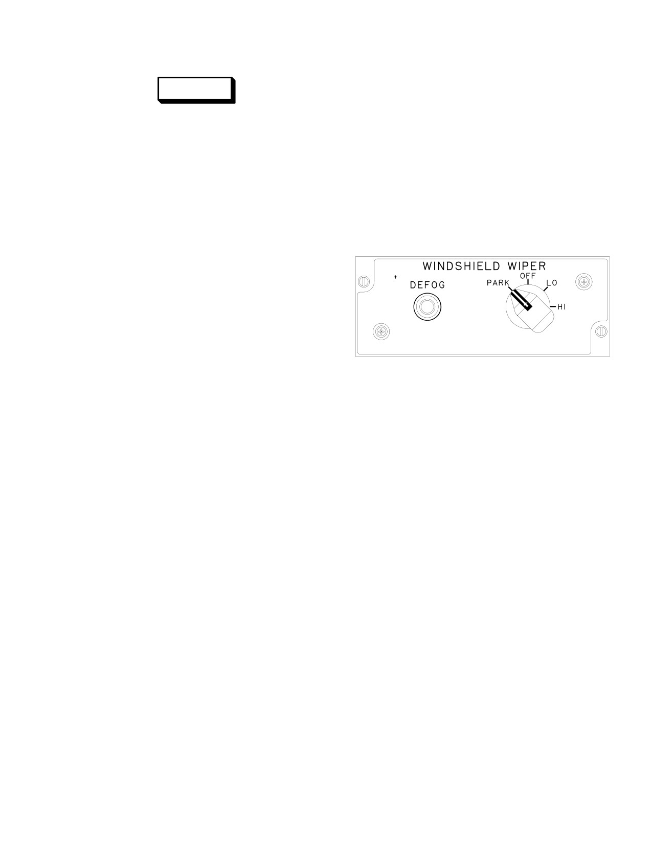
TM 1-1520-251-10
2.93.1 Windshield wipers. Two electrically driven wip-
WARNING
ers are mounted on the canopy frame to remove moisture
from the two windshields. The wipers have two speeds
Do not touch TADS/PNVS shroud win-
and a park position and are controlled by the WIND-
dows. Electrical shock can result, and
SHIELD panel WIPER rotary switch (fig 2-74) in each
heaters in these fairings can cause seri-
crew station.
ous burns. If shock or burns occur, seek
medical aid.
2.93.2 Canopy Defog. Pressurized hot air is mixed
with crew station conditioned air and directed against the
2.92.6 TADS/PNVS SENSOR Anti-Ice.
canopy side panels to defog them. Canopy defog is con-
trolled by the WINDSHIELD panel DEFOG pushbutton
a. Inflight. SENSOR anti-ice prevents ice formation
switch (fig 2-74) in each crew station.
on turret shrouds, boresight and sensor modular win-
dows. Anti-icing is accomplished via thermostatically con-
trolled heating elements in the shrouds and electronically
regulated power through the conductive window coatings.
ÑÑÑ
b. GND Position. The SENSOR anti-ice is inhibited
from operation when the helicopter is on the ground. This
ÑÑÑ
inhibit may be overridden by using the sensor anti-ice
ÑÑÑ
ground (GND) override on/off button (fig 2-73).
2.93 RAIN REMOVAL
LBA0024
The rain removal system consists of two Windshield wip-
ers and canopy defog.
Figure 2-74. Windshield Panel
Use or disclosure of this information is subject to the restriction(s) on the title page of this document.
2-77
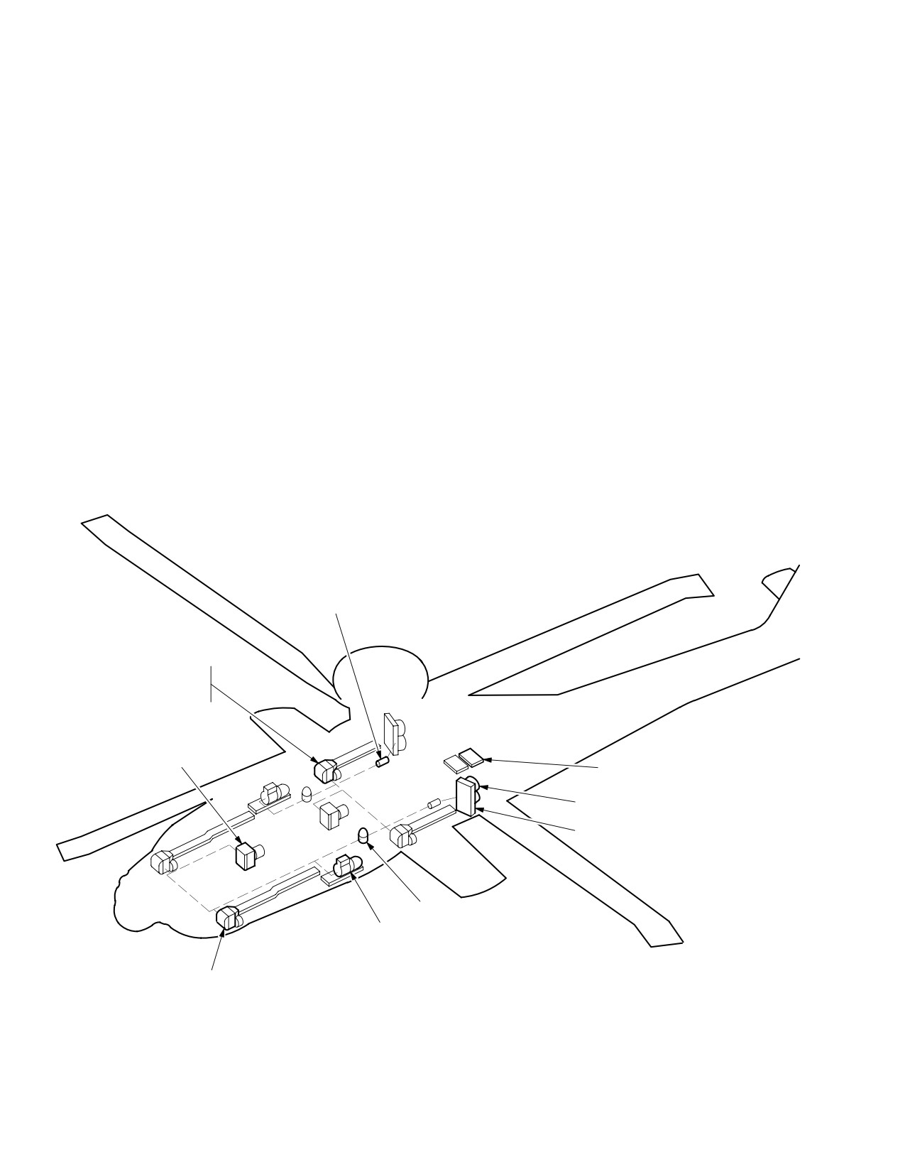
TM 1-1520-251-10
Section X. ENVIRONMENTAL CONTROL SYSTEM
2.94 ENVIRONMENTAL CONTROL SYSTEM (ECS)
• Operating the aircraft in a loose grass en-
vironment could cause the ECS condens-
er inlet to become clogged. This could re-
The ECS (fig 2-75) provides crew station ventilation, heat-
sult in a single or double condenser
ing, and Vapor Cycle Cooling System (VCCS) air condi-
overtemp condition.
tioning. The VCCS is the primary source of cool air for the
Extended Forward Avionics Bays (EFAB) and the TADS/
PNVS. No heating is required in the EFABs.
2.94.1 ECS Normal Operation. Environmental cooling
is provided by two independently operated VCCS sys-
tems. Crewstation heating uses bleed air from the main
NOTE
engines or APU via the IPAS. System control is performed
by the Digital Control Unit (DCU). One VCCS system will
• During engine starts in the heating mode,
service the aft right and left hand EFAB and the pilot crew
conditioned air will cease to be provided
station. The other system will service the forward right and
until starter drop-out. Non-conditioned
left hand EFAB, CPG crew station and the TADS/PNVS.
airflow will continue.
The aft avionics bays are supplied ambient air circulation
• When a canopy door is unlatched, cool-
via a fan. Temperature sensors, located in each crew sta-
ing air will not be provided to that
tion and EFAB, provide temperature status to the ap-
crewstation (heating mode is unaffected
propriate VCCS system allowing independent crew sta-
by canopy position).
tion and EFAB cooling.
RECEIVER/FILTER/DRYER (2 PL)
AFT EVAPORATOR WITH
THERMAL EXPANSION
VALVE/FAN (2 PL)
EVAPORATOR WITH
THERMAL EXPANSION
VALVE/BLOWER (2 PL)
CONTROLLER (2 PL)
BLOWER (4 PL)
CONDENSER (2 PL)
OIL SEPARATOR (2 PL)
COMPRESSOR (2 PL)
FWD EVAPORATOR WITH
THERMAL EXPANSION
VALVE/FAN (2 PL)
LBA2391
Figure 2-75. Environmental Control System (ECS)
Use or disclosure of this information is subject to the restriction(s) on the title page of this document.
2-78
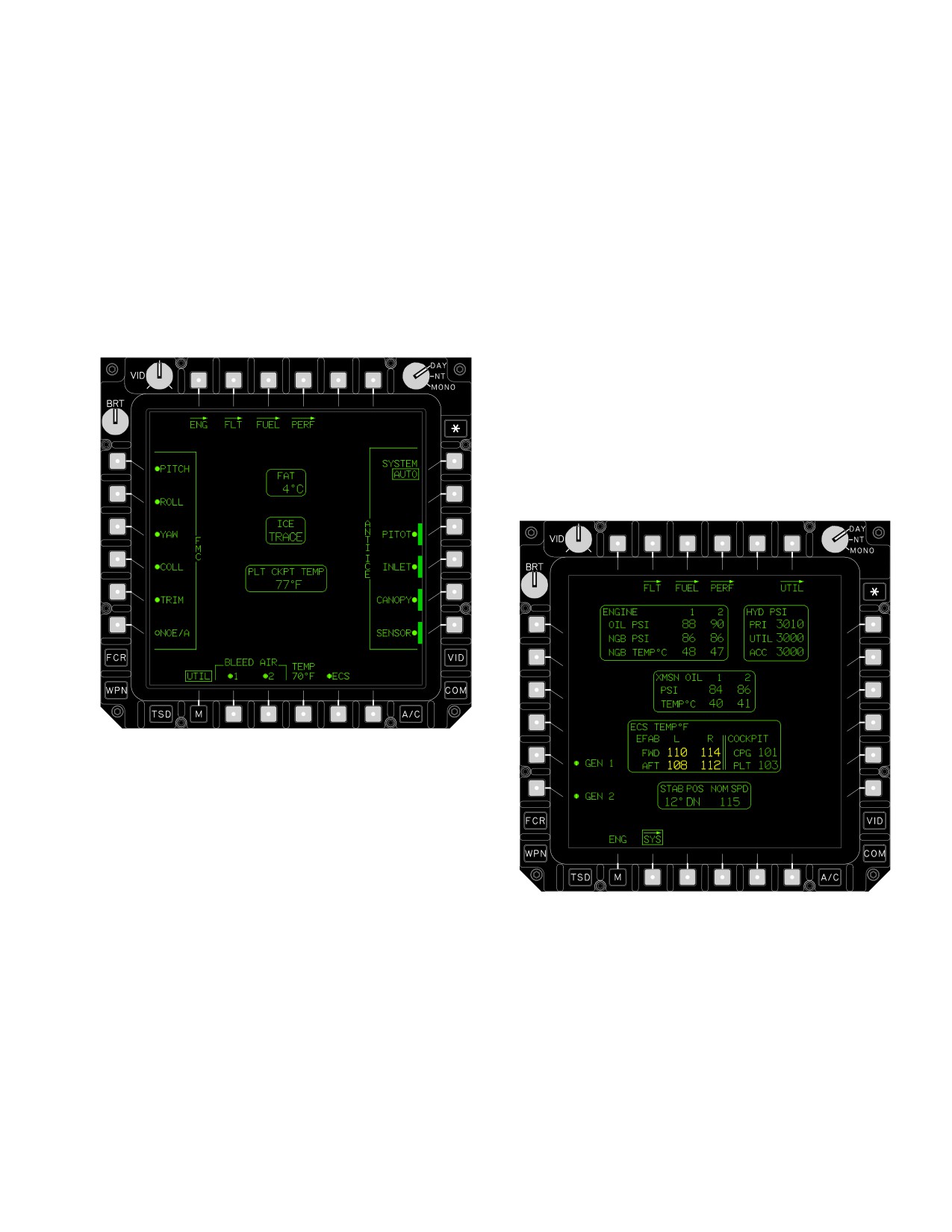
TM 1-1520-251-10
2.94.2 ECS Controls and Displays. Controls and dis-
b. TEMP Set Button. After crewmember selects
plays required to manage the ECS are provided on the
TEMP button, the desired crew station temperature is en-
A/C UTIL page (fig 2-76) and the SYS page. ECS controls
tered in 1° increments, 50° F to 90° F, via the Keyboard
consist of an ECS ON/OFF button, a data entry TEMP
Unit (KU). The crewmember then selects ENTER on the
(temperature) set button and a current crew station TEMP
KU and the new temperature setting will be displayed
status window located on the A/C UTIL page. Individual
above the TEMP button. Upon aircraft power up, TEMP
crew compartment air temperature readouts are dis-
will default to the last value set prior to shutdown. This
played on the SYS page. ECS variables involving the
data entry is independent in each crewstation.
equipment, EFABS, and crewstations can be viewed on
the ECS page.
c. Temperature Status Windows. The current
crew station ambient temperature is displayed in the
TEMP status window on the A/C UTIL page (fig 2-76).
The range value for the PLT/CPG CKPT TEMP status
window is from - 65° F to +160° F in 1° increments. Each
crewstation and EFAB compartment (left/right/forward
and aft) temperature is displayed in the ECS TEMP° F sta-
tus window on the SYS page (fig 2-77). An EFAB compart-
ment temperature is displayed in YELLOW when it is
greater than 105°. The range value for the ECS TEMP° F
window is from - 65° F to +160° F and displayed in 1° in-
crements.
LBA2547
Figure 2-76. A/C UTIL Page (Pilot)
a. ECS ON/OFF Button. The ECS button toggles
LBA2392A
the ECS between ON and OFF. Upon aircraft power up,
the ECS defaults ON.
Figure 2-77. SYS Page
Use or disclosure of this information is subject to the restriction(s) on the title page of this document.
2-79
TM 1-1520-251-10
2.95 CREWSTATION BACKUP COOLING
CAUTION
During most ECS failure modes, the EFAB and crewsta-
tion blowers will continue to circulate air to each compart-
To obtain optimum performance from the
ment, and the Air Particle Separator (APS) will provide
heating and cooling system, the gaspers
ambient air to the crewstations. There is one interconnect
must be full open. Adjusting the temper-
valve located in the air distribution ducting between the
ature level rather than closing gaspers
two crewstations. In the event of a cockpit cooling failure,
will increase the reliability of the blower.
the Digital Control Unit (DCU) will send a signal to the in-
Closing two or more gaspers will cause
terconnect valve to fully open the valve, thus allowing air-
the blower to operate in a stall region, in-
flow between the two cockpits. The crewstation blower to
creasing noise levels. Operating with all
the affected crewstation will shut down and allow the re-
gaspers closed may cause the blower to
maining crewstation blower to supply both cockpits with
overheat and shutdown.
conditioned air. It is possible with an Air Particle Separator
and ECS failure that the blowers may be disabled and no
d. Crewstation Gasper Adjustment. Each
fresh air is provided.
crewstation air distribution system features two torso
gaspers, two head gaspers and two leg vents. The torso
2.95.1 ECS Failure. The system begins to monitor for
and head gaspers may be manually adjusted open or
ECS failure when generator power is applied. The ECS
closed for airflow regulation and may be positioned up to
failure caution occurs when the system processor detects
60° off centerline in any direction for crew comfort. The
various ECS failures. Failures of the forward and aft ECS
torso gaspers are located on the front instrument panel
systems are usually temporary and the blowers continue
facing the crewmember, while the head gaspers are lo-
to operate. Failure of the ECS control is usually perma-
cated over each shoulder of the crewmember. The leg
nent and the blowers may be disabled. The UFD/EUFD
vents are located above both legs of each crewmember
and MPD will display the related caution message.
and are not adjustable.
2.96 VENTILATING SYSTEM
In the event of an ECS failure, the EFABS and crew sta-
tion blowers will continue to circulate air to each compart-
ment, and the Air Particle Separator (APS) will provide
ambient air to the crew stations. In the event of an ECS
and APS failure the blowers may be disabled and no fresh
air is provided.
Use or disclosure of this information is subject to the restriction(s) on the title page of this document.
2-80
Change 2
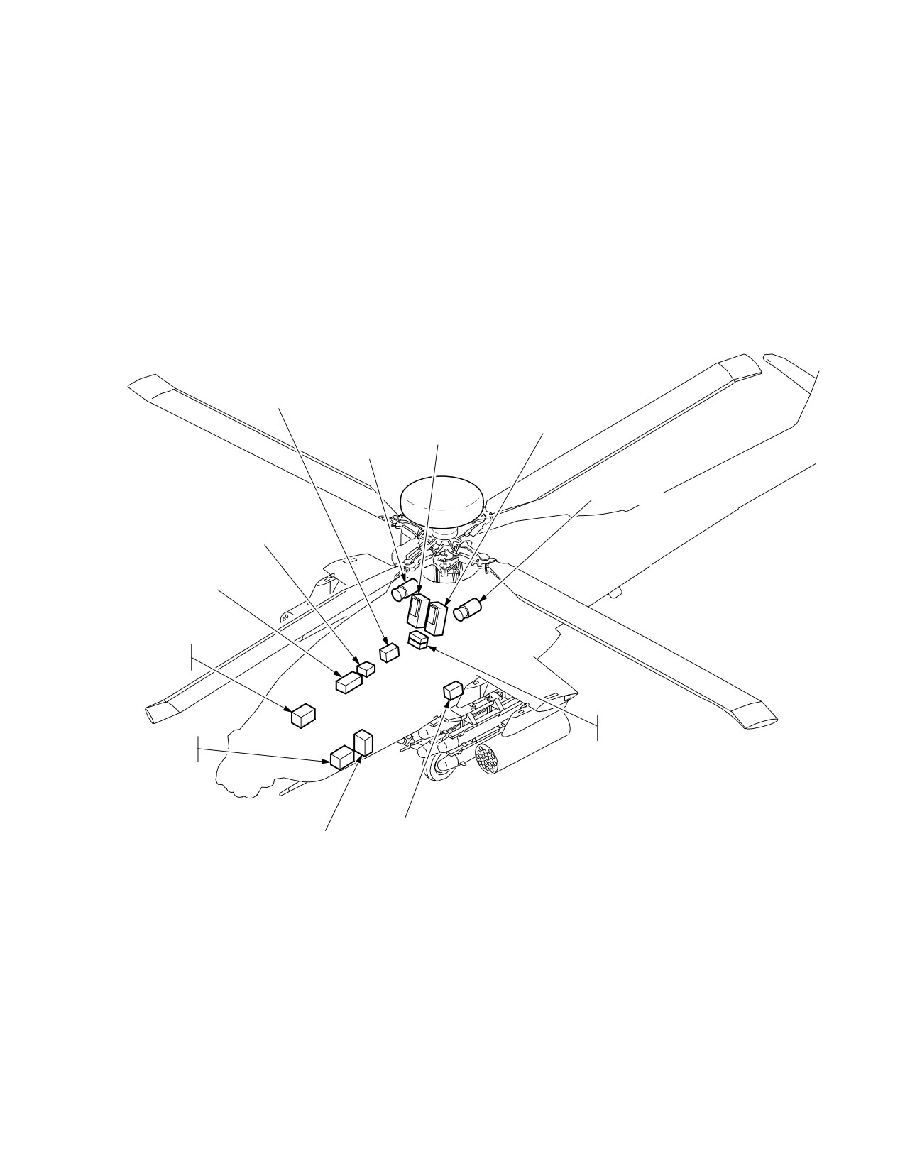
TM 1-1520-251-10
Section XI. ELECTRICAL SYSTEM
2.97 INTRODUCTION
ing Modules (HPSM) and two Electrical Load Centers
(ELC). On each HPSM is mounted a Circuit Breaker Panel
The electrical system (fig 2-78) produces and distributes
(CBP). The EPMS and the CBPs provide distribution for
all of the electrical power required for operation of the heli-
AC, DC, battery power, and ground power. EPMS opera-
copter. The electrical system provides: AC power genera-
tion is fully automated. Because of redundancy, there are
tion, DC power generation, and battery power.
no normal indications for the EPMS subsystem). Failures
within the EPMS are displayed on the MPD Data Manage-
2.98 ELECTRICAL POWER MANAGEMENT SYSTEM
ment System (DMS) page (refer to Section XVI). Busses
(EPMS)
1, 3 and 5 are tied together in each of the respective pow-
er distribution systems as are busses 2, 4 and 6
The EPMS (fig 2-79) consists of two High Power Switch-
(Figs 2-80,2-81 ,2-82 ,2-83).
CIRCUIT BREAKER
CIRCUIT BREAKER
PANEL q1 AND
TRANSFORMER
PANEL q2 AND
HIGH POWER
RECTIFIER q2
HIGH POWER
SWITCHING
SWITCHING
MODULE q1
MODULE q2
GENERATOR 2
GENERATOR 1
BATTERY
CHARGER
BATTERY
ELECTRICAL
LOAD CENTER q2
GENERATOR
CONTROL UNITS
ELECTRICAL
LOAD CENTER q1
TRANSFORMER
LIGHTING
RECTIFIER q1
CONTROLLER
LBA2396
Figure 2-78. Electrical System Components
Use or disclosure of this information is subject to the restriction(s) on the title page of this document.
2-81
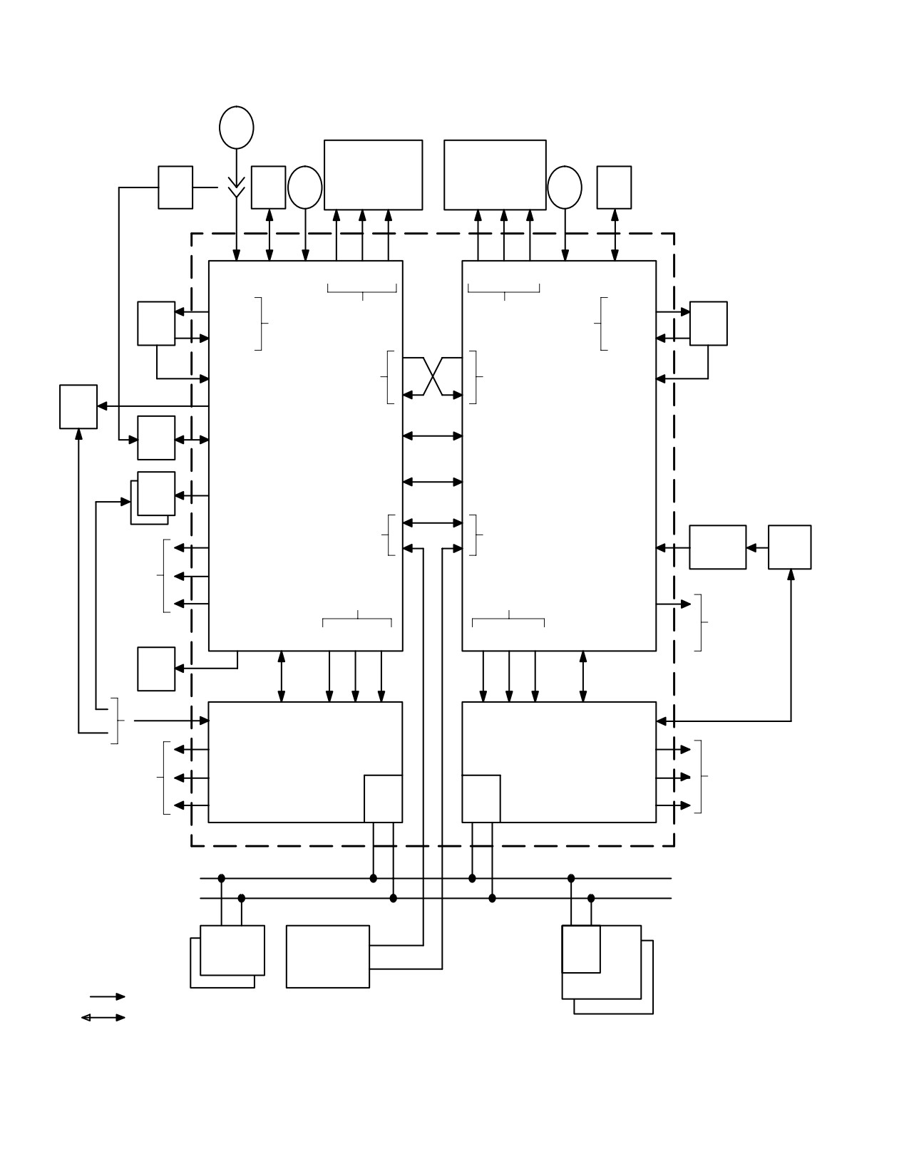
TM 1-1520-251-10
AGPU
1
CIRCUIT BREAKER PANELS
2
W
W
W
W
W
W
A
D
B
B
D
A
EPM
GCU1
GEN1
5
5
5
6
6
6
GEN2
GCU2
EPMS
EXT AC IN
AC IN
AC DC BAT
BAT DC AC
AC IN
MON/CTL
AC OUT
CBP FEEDERS
CBP FEEDERS
AC OUT
TRU1
TRU
TRU
TRU2
DC IN
DC IN
AC BUS
AC BUS
MON/CTL
MON/CTL
TIE
TIE
MMA
AC
HPSM1
HPSM2
DC BUS
MIK
CTL
TIE
PSP
BAT
LPRF
AC,DC
CTL
CTL
AC
BATTERY
CHGR
A/C
DC
LOADS
HOT BAT
ELC1 FEEDERS
ELC2 FEEDERS
AC
A/C
LOADS
DC
MON/CTL AC DC BAT
BAT DC AC MON/CTL
RFI
CTL
MON/CTL W
W
W
W
W
W
MON/CTL
CTL
A
D
B
B
D
A
3
3
3
4
4
4
AC
AC
A/C
ELC 2
A/C
ELC 1
DC
DC
LOADS
LOADS
RT
RT
BAT
BAT
AVIONICS DATA BUS
WEAPONS
UTIL RELAY
BC
PROCS
PANEL
LEGEND:
SYS PROCS
ELECTRICAL POWER
SIGNAL I/O
LBA2393
Figure 2-79. Electrical Power Management System
Use or disclosure of this information is subject to the restriction(s) on the title page of this document.
2-82
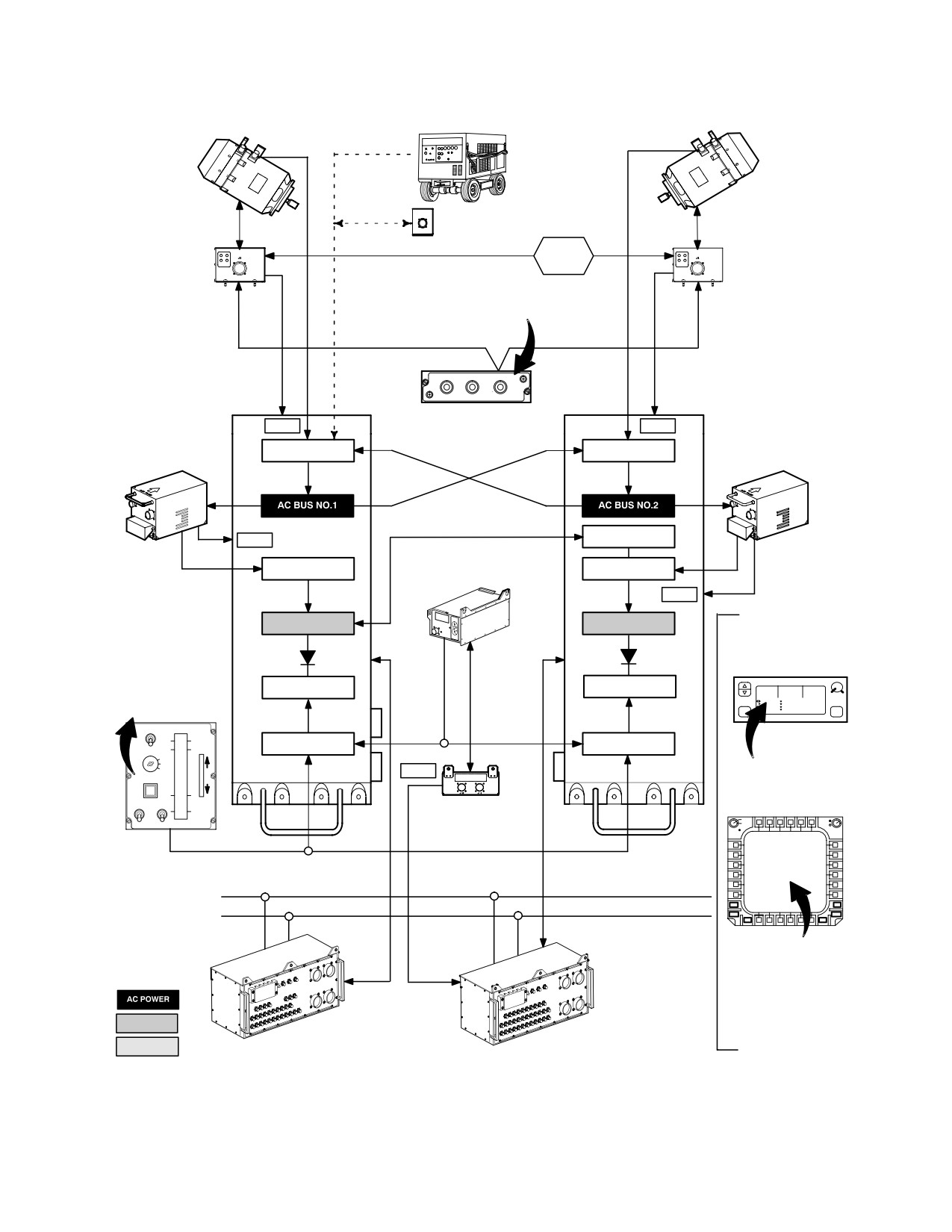
TM 1-1520-251-10
115/200 VAC 3PHASE 400 HERTZ
AVIATION GROUND POWER UNIT
115/200 VAC 3PHASE 400 HERTZ
NO. 1 AC
NO. 2 AC
GENERATOR
GENERATOR
EXTERNAL
POWER
GCU 1
MONITOR
GCU 2
SQUAT
SWITCH
OVERSPEED TEST PANEL
NO. 1 & NO. 2
GENERATOR
RESET
HIGH POWER
CHK OVSP TEST
GEN RST
HIGH POWER
ÍÍ
ENG 1
Í
SWITCHING
OFF
GEN 1
GEN 2
SWITCHING
CKT A
ENG 2
CKT B
MODULE NO. 1
MODULE NO. 2
Í
ÍÍ
FAIL
FAIL
NO. 1 REGULATED
NO. 2 REGULATED
TRANSFORMER
AC CONTACTOR
AC CONTACTOR
TRANSFORMER
RECTIFIER UNIT
RECTIFIER UNIT
DC BUS TIE
FAIL
115/200 VAC
FIBROUS
115/200 VAC
3PHASE
DC CONTACTOR
NICKEL
DC CONTACTOR
3PHASE
TO 28 VDC
CADMIUM
TO 28 VDC
BATTERY
FAIL
DC BUS NO. 1
DC BUS NO. 2
CAUTIONS
WARNINGS
ADVISORIES
PILOT’S POWER
UPFRONT DISPLAY
QUADRANT
VIEW
RTS
ENG1 OUT CAUTIONS ADVISORIES
ÄÄBAT BUS NO. 1Ä
ÄBAT BUS NO. 2ÄÄ
MASTER IGNITION
VH
H8G65
139.50
149.500249.500
RTS
UH
P3R56 C3 GJ8L52 C5 H
240.07545.07
45.550
LAST
KEY SWITCH
F1F2
B5Z23 C2
49.50XPNORM 5000 B
10:56:01 L
69.525
ÄÄÄÄÄ
ÄÄÄÄÄ
ÍRTR B
OFFBRK
LOCK
Í
GEN1 FAIL
LOCK
OUT
BAT CONTACTOR
BAT CONTACTOR
GEN2 FAIL
MSTR IGN
FLY
OFF
INC
RECT1 FAIL
BATT
RECT2 FAIL
EXT
FR
FAIL
PWR
I
BATTERY
APU
CT
CHARGER
Í
Í
ON
IDLE
DECR
MULTIPURPOSE DISPLAY
ENG START
STARTOFF
OFF
BATTERY CHARGER
DAY
BRT
NIGHT
CON
ÍNO.IGN ORIDE. 2 Í
SYMBRT
AVIONICS DATA BUS
FCR
VID
WPN
COM
TSD
M
A/C
BATTERY FAIL
BATTERY CHARGER FAIL
GENERATOR 1 FAIL
GENERATOR 2 FAIL
LEGEND:
GENERATOR CONTROL UNIT 1 FAIL
GENERATOR CONTROL UNIT 2 FAIL
TRANSFORMER/RECT 1 FAIL
TRANSFORMER/RECT 2 FAIL
HPSM 1 _ _ _ _ FAIL
DC POWER
HPSM 2 _ _ _ _ FAIL
ELECTRIC LOAD
ELC 1 _ _ _ _ FAIL
CENTER NO. 1
ELECTRIC LOAD
BATT POWER
ELC 2 _ _ _ _ FAIL
CENTER NO. 2
LBA2561
Figure 2-80. Electrical Power Distribution
Use or disclosure of this information is subject to the restriction(s) on the title page of this document.
2-83
TM 1-1520-251-10
• ECS COMP 1
• ECS COMP 2
• FCR
• ELC2 AC
• ELC1 AC
• AIR DATA SENSOR HTR
• P2 1760 AC
• P1 1760 AC
• CPG FLT CONT (REF B)
• AIR DATA SENSOR HTR
• WP/SP1&2/STAB SYN (REF C)
• P2 1760 AC
• ICE PROBE HEATER
• CPG FLT CONT (REF B)
•
AWS AC
• P3 1760 AC
• P4 1760 AC
• GUN MOTOR
• AFT COND BLOWER B
• ANTICOLL/ FORM LTS
• DISPL PROC q2
• ENG1 OVSP
• IHADSS DEU
• LASER EU
• NITROGEN INERT
• PNVS EU
• ENG2 OVSP
• DISPL PROC q1
• AFT COND BLOWER A
• NOSE GRBX HEATER 1
• ORT
• PLT LH MPD
• CPG LH MPD
• IHADSS SEU
• VIDEO RCDR
• CPG RH MPD
• GND SVC RECPT AC
• FWD COND BLWR A
• AMMO MOTOR
• FWD LH/RH FAB FANS
• AFTLH/RH FAB FANS
• CPG CKPT FAN
• FANENG BLEED AIR
• AIR PARTICLE SEP FAN
• NOSE GRBX HEATER 2
• FWD COND BLWR B
• PLT RH MPD
• RH/LH FANSAFT BAYS
• BATTERY CHARGER
• TADS PWR SUPPLY
• PLT CKPT FAN
LBA2562
• CANOPY HEATER
Figure 2-81.
[
BLK 1
AC Power Distribution]
Use or disclosure of this information is subject to the restriction(s) on the title page of this document.
2-84
Change 2
TM 1-1520-251-10
•
AFT LH FAB FAN
•
AFT COND BLOWER A
•
AIR PARTICLE SEP
•
AFT COND BLOWER B
•
ANTI COLL/FORM LTS
•
AFT RH FAB FAN
•
CPG CKPT FAN
•
AMMO MOTOR
•
CPG RH MPD
•
BATTERY CHARGER
•
DISPL PROC #1
•
CANOPY HEATER
•
ECS COMP 1
•
CPG LH MPD
•
ELC1 AC
•
DISP PROC #2
•
ENG 1 OVSPD
•
ECS COMP 2
•
FCR
•
ELC2 AC
•
FWD COND BLWR A
•
ENG2 OVSPD
•
FWD COND BLWR B
•
FANENG BLEED AIR
•
FWD LH FAB FAN
•
FWD RH FAB FAN
•
GUN MOTOR
•
GND SVC RECPT AC
•
HF ARC220 FAN
•
IHADSS DEU
•
IHADSS SEU
•
NITROGEN INERT
•
LASER EU
•
NOSE GRBX HEATER 2
•
NOSE GRBX HEATER 1
•
PLT CKPT FAN
•
PLT LH MPD
•
PLT RH MPD
•
PNVS EU
•
RH/LH FANS AFT BAYS
•
TADS PWR SUPPLY
• AIR DATA SENSOR
• AWS AC
• IAFS FUEL PUMP
• CPG FLT CONT (REF B)
• ICE PROB HEATER
• P1 1760 AC
• P2 1760 AC
• P3 1760 AC
• P4 1760 AC
• WP&SP 1&2/STAB SYN
• PLT FLT CONT (REF A)
LBA5167
Figure 2-81A.
[
BLK 2
AC Power Distribution ]
Use or disclosure of this information is subject to the restriction(s) on the title page of this document.
Change 2
2-84.1

TM 1-1520-251-10
DC BUS NO. 1
DC BUS NO. 2
•
IR JAM SOURCE/ELX/FAN
•
ELC2 DC
•
PSP/LPRF
•
RFI
•
ELC1 DC
DC BUS NO. 3
DC BUS NO. 4
•
ENG1 AI/START BL V/ NGB HTR 1
•
ENG2 AI/START BL VLV/ NGB HTR 2
•
LW ROCKET ARM
•
IHADSS DEU PWR
•
LWT 1760 DC2
•
RW PITOT HTR
•
RDR WRN RCVR
•
RWT 1760 DC2
•
TADS STANDBY
•
RW ROCKET ARM
•
CANOPY HEAT/DEFOG V
•
ICE SIG PROC/ ASP SOV
•
CHAFF ARM
•
RWT 1760 DC1
•
LWT 1760 DC1
•
IHADSS SEU PWR
•
FUEL VALVE
•
RDR ALTM PWR
•
P2 1760 DC1
•
P3 1760 DC1
•
P2 1760 DC2
•
P3 1760 DC2
•
P1 1760 DC1
•
P4 1760 DC1
•
P1 1760 DC2
•
P4 1760 DC2
•
ELC1 DC CONT
•
ELC2 DC CONT
•
LW PITOT HTR
•
GUN ARM
•
PNVS STANBY
•
DPLR SENSOR
•
LASER WRN RCVR
DC BUS NO. 5
DC BUS NO. 6
•
EGI 1A
•
PRI LT CPG
•
STAB ACTR RH
•
NAV LTS/ANTI COL
•
DCU 1
•
PRI LT PLT
•
P3 ACTR PWR
•
P3 PIU PWR
•
P2 PIU PWR
•
GRBX XDCR
•
WSHLD WPR CPG
•
EGI 2B
•
ENG CHOP
•
RADAR JAM
•
BUCS/FMC CMPTR
•
KEYBD CPG
•
KYBD PLT
•
EGI ANT SPLITTER
•
PNVS EU
•
WPNS PROC q2
•
STAB ACTR LH
•
CPG SIGHT SW
•
AREA WPNS SYS DC
•
GND SVC RECPT DC
•
P2 ACTR PWR
•
PLT SIGHT SW
•
STAB CNTRL
•
FUZZ BURNER
•
SELECT JTSN
•
EGI 2A
•
P4 ACTR PWR
•
SIDE LOADER
•
FAN AFT BAY
•
IR JAM CONTRL
•
P4 PIU PWR
•
HADS
•
PLT CBR FLTR BLWR
•
TADS/PNVS
•
BATT HTR
•
EGI 1B
•
WPNS PROC q1
•
TESS TECU
•
DCU 2
•
ADF
•
P1 ACTR PWR
•
TESS TLIA
•
CPG CBR FLTR BLO
•
WSHLD WPR PLT
•
P1 PIU PWR
•
TESS LRFD
LBA2563
Figure
2-82.
[
BLK 1
DC Power Distribution ]
Use or disclosure of this information is subject to the restriction(s) on the title page of this document.
2-84.2
Change 2
TM 1-1520-251-10
DC BUS NO. 1
DC BUS NO. 2
•
DCU 1
• PLT CBR FLTR BLWR
• ADF
•
NAV LTS/ANTI COL
•
EGI 1A
• PLT SIGHT SW
• AREA WPNS SYS DC
•
P3 ACTR PWR
•
EGI 2A
• PRI LT CPG
• BATT HTR
•
P3 PIU PWR
•
EGI ANT SPLITTER
• PRI LT PLT
• BUCS/FMC CMPTR
•
P4 ACTR PWR
•
ELC1 DC
• PSP/LPRF
• CPG CBR FLTR BLO
•
PNVS EU
•
ENG CHOP
• RADAR JAM
• CPG SIGHT SW
•
PR PIU PWR
•
FAN AFT BAY
• RFI
• DCU 2
•
SIDE LOADER
•
GRBX XDCR
• SELECT JTSN
• EGI 1B
•
STAB ACTR RH
•
IAFS FUEL QTY
• STAB ACTR LH
• EGI 2B
•
STAB CNTRL
•
IR JAM CONTROL
• TADS/PNVS
• ELC2 DC
•
VIDEO RCDR
•
KYBD PLT
• TESS LRFD
• FUZZ BURNER
•
WPNS PROC #2
•
P1 ACTR PWR
• TESS TECU
• GND SVC RECPT DC
•
WSHLD WPR CPG
•
P1 PIU PWR
• TESS TLIA
• HADS
•
WSHLD WPR PLT
•
P2 ACTR PWR
• WPNS PROC #1
• KEYBD CPG
•
P2 PIU PWR
DC BUS NO. 3
DC BUS NO. 4
•
CANOPY HEAT
•
DPLR SENSOR
•
CHAFF ARM
•
ELC2 DC CONT
•
ELC1 DC CONT
•
ENG2 AI/START BL
•
ENG1 A1/START BL
•
GUN ARM
•
FUEL VALVE
•
ICE SIG PROC/ASP SOV
•
IAFS CTRL
•
IHADSS DEU PWR
•
LASER WRN RCVR
•
IHADSS SEU PWR
•
LW PITOT HTR
•
P3 1760 DC1
•
LW ROCKET ARM
•
P3 1760 DC2
•
LWT 1760 DC1
•
P4 1760 DC1
•
LWT 1760 DC2
•
P4 1760 DC2
•
P1 1760 DC1
•
RDR ALTM PWR
•
P1 1760 DC2
•
RESERVED FOR ROTOR
•
P2 1760 DC1
•
RW PITOT HTR
•
P2 1760 DC2
•
RW ROCKET ARM
•
PNVS STANDBY
•
RWT 1760 DC1
•
RDR WRN RCVR
•
RWT 1760 DC2
•
TADS STANDBY
LBA5168
Figure 2-82A.
[
BLK 2
DC Power Distribution ]
Use or disclosure of this information is subject to the restriction(s) on the title page of this document.
Change 2
2-84.3

TM 1-1520-251-10
ÄÄÄBATT BUS NO. 1ÄÄÄÄ
ÄÄÄBATT BUS NO. 2ÄÄÄ
ÄÄÄÄÄÄÄÄÄÄÄ
ÄÄÄÄÄÄÄÄÄÄ
ÄÄÄBATT BUS NO. 3ÄÄÄÄ
ÄÄÄBATT BUS NO. 4ÄÄÄ
• ELC1 BAT CONT
• ELC2 BAT CONT
• ENG1 ATS
• FUEL CRSFD2
• FUEL CRSFD1
• APU FUEL BOOST AND SOV
• ZEROIZE PNL
• FUEL BOOST SOV
• ENG1 OIL PRESS
• ENG2 ATS
• ENG1 BL LOUVER ON/OFF
• XFER AIR VALVE
• APU ECU PWR/START
ÄÄÄBATT BUS NO. 5ÄÄÄÄ
• ENG2 BL LOUVER ON/OFF
Ä•ÄFIRE DET ENG q1ÄÄÄÄÄ
• ENG2 OIL PRESS/TRANS XDCR
• LD MAINT/PRCS SEL
• VIDEO CONT PNL/BPIA
• IFM AMP
ÄÄÄÄÄÄÄÄÄÄÄ
• SQUAT SWITCH
ÄÄÄÄÄÄÄÄÄÄÄ
• FM2 ARC201
•
LDG SRCH LIGHT
• IDM
•
CIU
• TAIL WHL LOCK
•
UHF ARC 164
• RTR/TADS BRAKES
•
XPNDR/IFF
• EMER JTSN
•
UTIL LTS MAINT
• SEC/CPG ADV LTS
•
FIRE EXT PLT
• GEN 2 BACKUP
•
DATA XFR UNIT
• FIRE EXT CPG
•
SYS PROC q2
• FM1 ARC201
•
HYD PRESS XDCRS
• SYS PROC q1
•
INT GRBX TEMP ALM
• UPFRONT DSPL PLT
•
UTIL RLY PNL
• CPG PWR LEVER
•
VHF ARC 186
•
KY58
ÄÄÄÄÄÄÄÄÄÄÄ
•
REFUEL PNL
ÄÄÄBATT HOT BUSÄÄÄÄ
•
EMG S/O VALVE
• COLD RFL
•
PLT ADV LT
• MIK SW
•
UPFRONT DSPL CPG
• HPSM1 CONT
•
FIRE DET ENG q2
• HPSM2 CONT
•
FIRE DET APU
•
STBY INSTR
•
MDR
NOTE: ALL EQUIPMENT LISTED ABOVE ON BATTERY BUSSES 1
THROUGH 6 WILL BE POWERED BY BATTERY POWER IN
•
GEN 1 BACKUP
THE EVENT OF AN ELECTRICAL FAILURE.
•
FLT CNTRL TRIM
LBA2564
Figure 2-83.
[
BLK 1
Battery Power Distribution ]
Use or disclosure of this information is subject to the restriction(s) on the title page of this document.
2-84.4
Change 2
TM 1-1520-251-10
ÄÄÄÄÄÄBATT BUS NO. 1ÄÄÄÄÄ
ÄÄÄÄÄBATT BUS NO. 2ÄÄÄÄÄ
Ä•ÄÄÄÄÄÄÄ•ÄÄÄÄÄÄ
•ÄCIUÄÄÄÄÄÄ•ÄMDRÄÄÄÄ
CPG PWR LEVER
IDM
• EMER JTSN
• IFM AMP
• DATA XFR UNIT
• PLT ADV LTS
• FIRE DET ENG #1
• LD MAINT PRCS SEL
• EMG S/O VALVE
• REFUEL PNL
• FIRE EXT CPG
• RTR/TADS BRAKES
• FIRE DET APU
• STDBY INSTR
•
FM1 ARC201
• SEC/CPG ADV LTS
• FIRE DET ENG #2
• SYS PROC #2
• FM2 ARC201
• SQUAT SWITCH
• FIRE EXT PLT
• UHF ARC164
• GEN 2 BACKUP
• SYS PROC #1
• FLT CNTRL TRIM
• UPFRONT DSPL CPG
• HF ARC220
• TAIL WHL LOCK
• GEN 1 BACKUP
• UTIL LTS MAINT
• HF KY100
• UPFRONT DISPL PLT
• HYD XDCR PRI/EMER
• UTIL RLY PNL
• HYD XDCR UTIL
• INT GRBX TEMP ALM
• VHF ARC186
• KY58
• XPNDR/IFF
• LDG SRCH LIGHT
ÄÄÄÄÄÄÄÄÄÄ
ÄÄÄÄÄÄÄÄÄÄÄ
ÄÄÄBATT BUS NO. 3ÄÄÄ
ÄÄÄBATT BUS NO. 4ÄÄÄÄ
• ELC1 BAT CONT
• APU ECU PWR/START
• ENG1 ATS
• APU FUEL BOOST AND
• ENG1 BL/LOUVER
• ELC2 BAT CONT
• ENG1 OIL PRESS
• ENG2 OIL
• FDMU PROVISION
• ENG2 ATS
• FUEL CRSFD1
• ENG2 BL/LOUVER
• ZEROIZE PNL
• FUEL BOOST SOV
• FUEL CRSFD2
• VIDEO CONT PNL/BPIA
• XFER AIR VALVE
ÄÄÄÄÄÄÄÄ
ÄÄÄÄÄÄÄÄ
• COLD RFL PANEL
• HPSM1 CONT
• HPSM2 CONT
• MIK SW & MDR
LBA5169
Figure 2-83A.
[
BLK 2
Battery Power Distribution ]
Use or disclosure of this information is subject to the restriction(s) on the title page of this document.
Change 2
2-84.5/(2-84.6 blank)
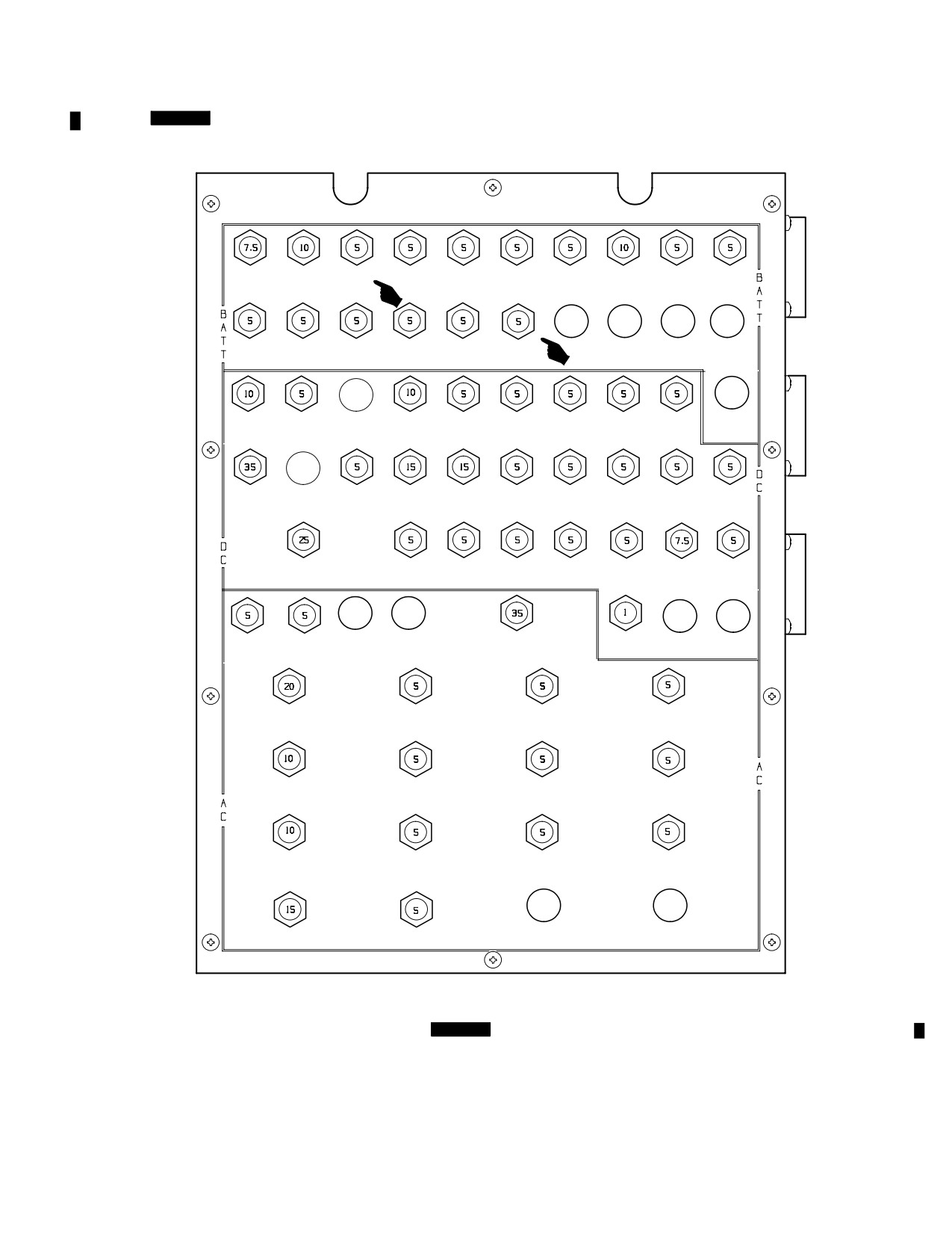
TM 1-1520-251-10
2.98.1 [
BLK 1
Circuit Breaker Panel (CBP) 1. CBP
switched secondary loads on the No. 1 busses. CBP 1 is
1 receives 115/200 Vac, 28 Vdc, and 24/28 Vdc input from
mounted on the forward face of HPSM 1. Figure 2-84
HPSM 1. It contains the CBs necessary to supply the un-
shows which CBs are located on CBP 1. ]
SEC/CPG
EMERG
RTR/TADS
TAIL WHL
IDM
FM2
SQUAT
IFM
LO MAINT
FIRE DET
ADV LTS
JISN
BRAKES
LOCK
ARC201
SWITCH
AMP
PRCS SEL
ENG q1
CPG PWR
UPFRONT
SYS PROC
FM1
FIRE EXT
GEN 2
LEVER
DSPL PLT
q1
ARC201
CPG
BACKUP
SELECT
P2 ACTR
STAB
KYBD
ENG
P2 PIU
OCU 1
EGI 1A
JTSN
PWR
ACTR LH
PLT
CHOP
PWR
RADAR
GRBX
PRI LT
PRI LT
P1 PIU
P1 ACTR
WPN PROC
PLT CBR
FAN AFT
JAM
XDCR
PLT
CPG
PWR
PWR
q1
FLTR BLWR
BAY
TADS/
EGI 2A
PLT SIGHT
CPG
EGI ANT
TESS
TESS
TESS
PNVS
SW
SIGHT SW SPLITTER
TECU
TLIA
LRFD
ENG1
ANTI COLL
GUN
IR JAM
OVSP
FORM LTS
MOTOR
CONTROL
NOSE GRBX
DISPL PROC
PNVS
LASER
HEATER 1
q1
EU
EU
FWD COND
CPG RH
IHADS
PLT LH
BLWR A
MPD
SEU
MPD
FWD COND
AIR PARTICLE
CPG CKPT
FWD LH/RH
BLWR B
SEP FAN
FAN
FAB FANS
TADS PWR
RH/LH FANS
SUPPLY
AFT BAYS
LBA23981A
CIRCUIT BREAKER PANEL 1
Figure 2-84.
[
BLK 1
Circuit Breaker Panel 1 ]
Use or disclosure of this information is subject to the restriction(s) on the title page of this document.
Change 2
2-85
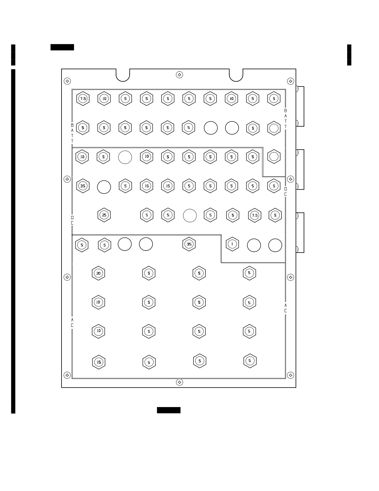
TM 1-1520-251-10
2.98.1A [
BLK 2
Circuit Breaker Panel
(CBP)
ply the unswitched secondary loads on the No. 1 busses.
1. CBP 1 receives 115/200 Vac, 28 Vdc, and 24/28 Vdc
CBP 1 is mounted on the forward face of HPSM 1. Figure
input from HPSM 1. It contains the CBs necessary to sup-
2-84A shows which CBs are located on CBP 1. ]
SEC/CPG
EMERG
RTR/TADS
TAIL WHL
IDM
FM2
SQUAT
IFM
LO MAINT
FIRE DET
ADV LTS
JISN
BRAKES
LOCK
ARC201
SWITCH
AMP
PRCS SEL
ENG q1
5
CPG PWR
UPFRONT
SYS PROC
FM1
FIRE EXT
GEN 2
HF
HYD XDCR
LEVER
DSPL PLT
q1
ARC201
CPG
BACKUP
UTIL
KY100
25
SELECT
P2 ACTR
STAB
KYBD
ENG
P2 PIU
OCU 1
EGI 1A
HF
JTSN
PWR
ACTR LH
PLT
CHOP
PWR
ARC220
RADAR
GRBX
PRI LT
PRI LT
P1 PIU
P1 ACTR
WPN PROC
PLT CBR
FAN AFT
JAM
XDCR
PLT
CPG
PWR
PWR
q1
FLTR BLWR
BAY
TADS/
EGI 2A
PLT SIGHT
EGI ANT
TESS
TESS
TESS
PNVS
SW
SPLITTER
TECU
TLIA
LRFD
ENG1
ANTI COLL
GUN
IR JAM
OVSP
FORM LTS
MOTOR
CONTROL
NOSE GRBX
DISPL PROC
PNVS
LASER
HEATER 1
q1
EU
EU
FWD COND
CPG RH
IHADS
PLT LH
BLWR A
MPD
SEU
MPD
FWD COND
AIR PARTICLE
CPG CKPT
FWD LH
BLWR B
SEP FAN
FAN
FAB FAN
TADS PWR
RH/LH FANS
FWD RH
HF ARC220
SUPPLY
AFT BAYS
FAB FAN
FAN
LBA5170
CIRCUIT BREAKER PANEL 1
Figure 2-84A.
[
BLK 2
Circuit Breaker Panel 1 ]
Use or disclosure of this information is subject to the restriction(s) on the title page of this document.
2-86
Change 2
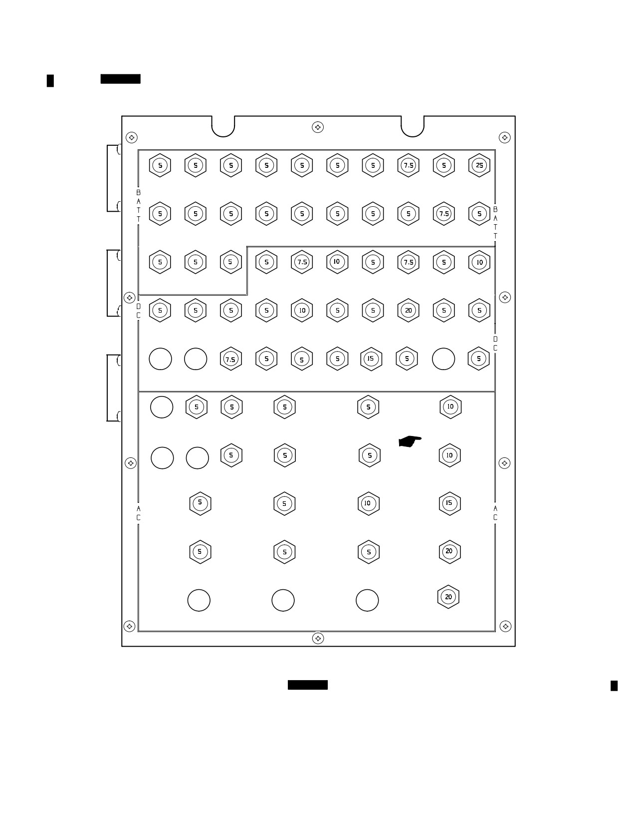
TM 1-1520-251-10
2.98.2 [
BLK 1
Circuit Breaker Panel (CBP) 2. CBP
switched secondary loads on the No. 2 busses. CBP 2 is
2 receives 115/200 Vac, 28 Vdc, and 24/28 Vdc input from
mounted on the forward face of HPSM 2. Figure 2-85
HPSM 2. It contains the CBs necessary to supply the un-
shows which CBs are located on CBP 2.]
INT GRBX HYD PRESS
SYS PROC
DATA XFR
FIRE
UTIL LTS
XPNDR/
VHF
CIU
LDG SRCH
IFF
ARC186
TEMP ALM XDCRS
q2
UNIT
EXT PLT
MAINT
LIGHT
STDBY
FIRE DET
FIRE DET
UPFRONT
PLT ADV
EMG S/O
REFUEL
KYSB
UHF
UTIL
INSTR
ARC164
APU
q2
DSPL CPG
LTS
VALVE
PNL
RLY PNL
FLT CNTRL GEN 1
MDR
STAB
AREA WPNS
PNVS
BUCS/FMC
WSHLD
P3 PAC
STAB
TRIM
SYS DC
EU
BACK UP
CNTRL
CMPTR
WPR CPG
PWR
ACTR RH
WPN PROC
KEYBD
EGI ZB
P3 PIU
NAV LTS/
CPG CBR
DCU 2
BATT
P4 PIU
P4 ACTR
q2
CPG
HTR
PWR
PWR
PWR
ANTICOL
FLTR BLO
WSHLD
ADF
EGI 1B
HADS
SIDE
FUZZ
GND SVC
WPR PLT
LOADER
BURNER
RECPT DC
ENG2
NITROGEN
IHADSS
DISPL PROC
AFT COND
OVSP
INERT
DEU
q2
BLOWER B
VIDEO
CPG LH
ORT
AFT COND
RCDR
MPD
BLOWER A
FANENG
FWD LH/RH
AMMO
GND SVC
BLEED AIR
FAB FANS
MOTOR
RECPT AC
PLT CKPT
BATTERY
PLT RH
NOSE GRBX
FAN
CHARGER
MPD
HEATER 2
CANOPY
HEATER
CIRCUIT BREAKER PANEL 2
LBA23982A
Figure 2-85.
[
BLK 1
Circuit Breaker Panel 2 ]
Use or disclosure of this information is subject to the restriction(s) on the title page of this document.
Change 2
2-87
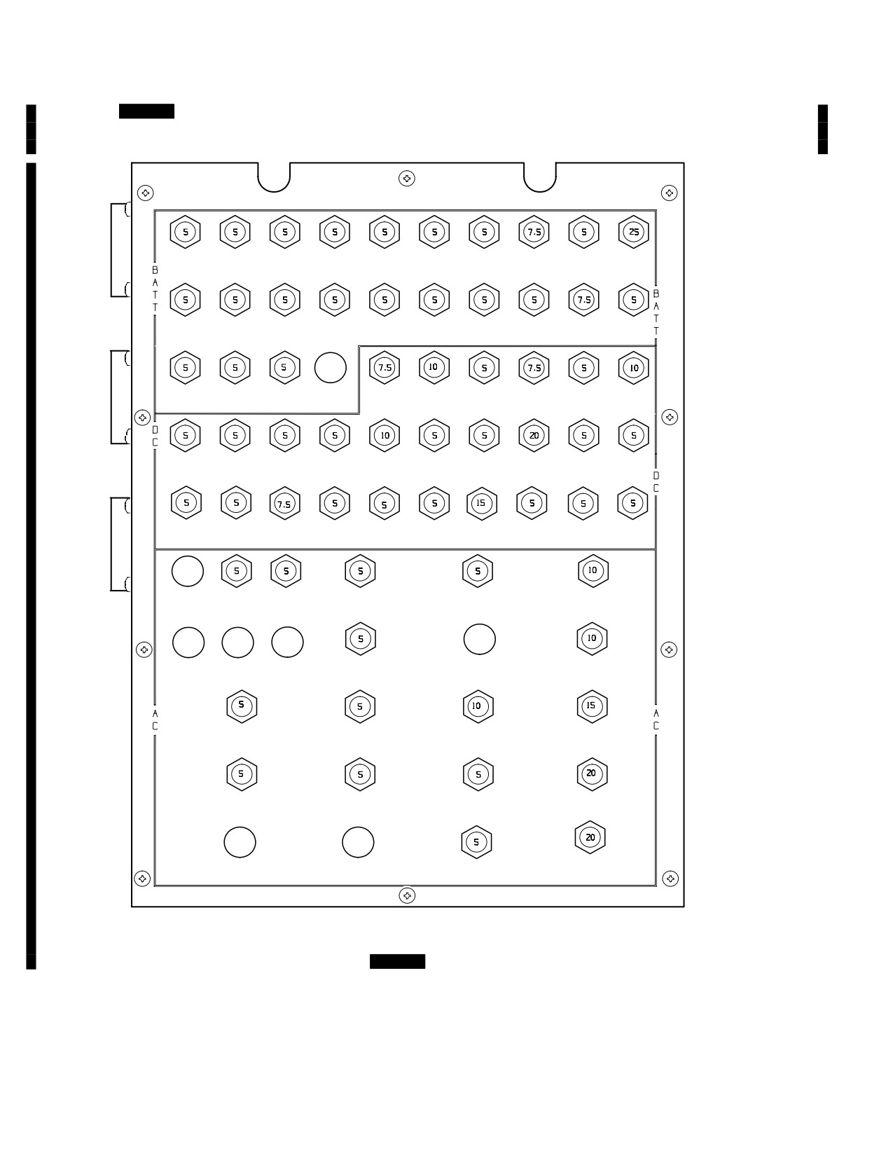
TM 1-1520-251-10
2.98.2A [
BLK 2
Circuit Breaker Panel
(CBP)
ply the unswitched secondary loads on the No. 2 busses.
2. CBP 2 receives 115/200 Vac, 28 Vdc, and 24/28 Vdc
CBP 2 is mounted on the forward face of HPSM 2. Figure
input from HPSM 2. It contains the CBs necessary to sup-
2-85A shows which CBs are located on CBP 2.]
INT GRBX HYD PRESS
SYS PROC
DATA XFR
FIRE
UTIL LTS
XPNDR/
VHF
CIU
LDG SRCH
IFF
ARC186
TEMP ALM PRI/EMER
q2
UNIT
EXT PLT
MAINT
LIGHT
STDBY
FIRE DET
FIRE DET
UPFRONT
PLT ADV
EMG S/O
REFUEL
KYSB
UHF
UTIL
INSTR
ARC164
APU
q2
DSPL CPG
LTS
VALVE
PNL
RLY PNL
FLT CNTRL GEN 1
MDR
AREA WPNS
PNVS
BUCS/FMC
WSHLD
P3 PAC
STAB
TRIM
SYS DC
EU
BACK UP
CMPTR
WPR CPG
PWR
ACTR RH
WPN PROC
KEYBD
EGI ZB
P3 PIU
NAV LTS/
CPG CBR
DCU 2
BATT
P4 PIU
P4 ACTR
q2
CPG
HTR
PWR
PWR
PWR
ANTICOL
FLTR BLO
CPG
STAB
WSHLD
ADF
EGI 1B
HADS
SIDE
FUZZ
VIDEO
GND SVC
SIGHT SW
CNTRL
WPR PLT
LOADER
BURNER
RCDR
RECPT DC
ENG2
NITROGEN
IHADSS
DISPL PROC
AFT COND
OVSP
INERT
DEU
q2
BLOWER B
CPG LH
AFT COND
MPD
BLOWER A
FANENG
AFT RH
AMMO
GND SVC
BLEED AIR
FAB FAN
MOTOR
RECPT AC
PLT CKPT
BATTERY
PLT RH
NOSE GRBX
FAN
CHARGER
MPD
HEATER 2
CANOPY
AFT LH
HEATER
FAB FAN
CIRCUIT BREAKER PANEL 2
LBA5171
Figure 2-85A.
[
BLK 2
Circuit Breaker Panel 2 ]
Use or disclosure of this information is subject to the restriction(s) on the title page of this document.
2-88
Change 2
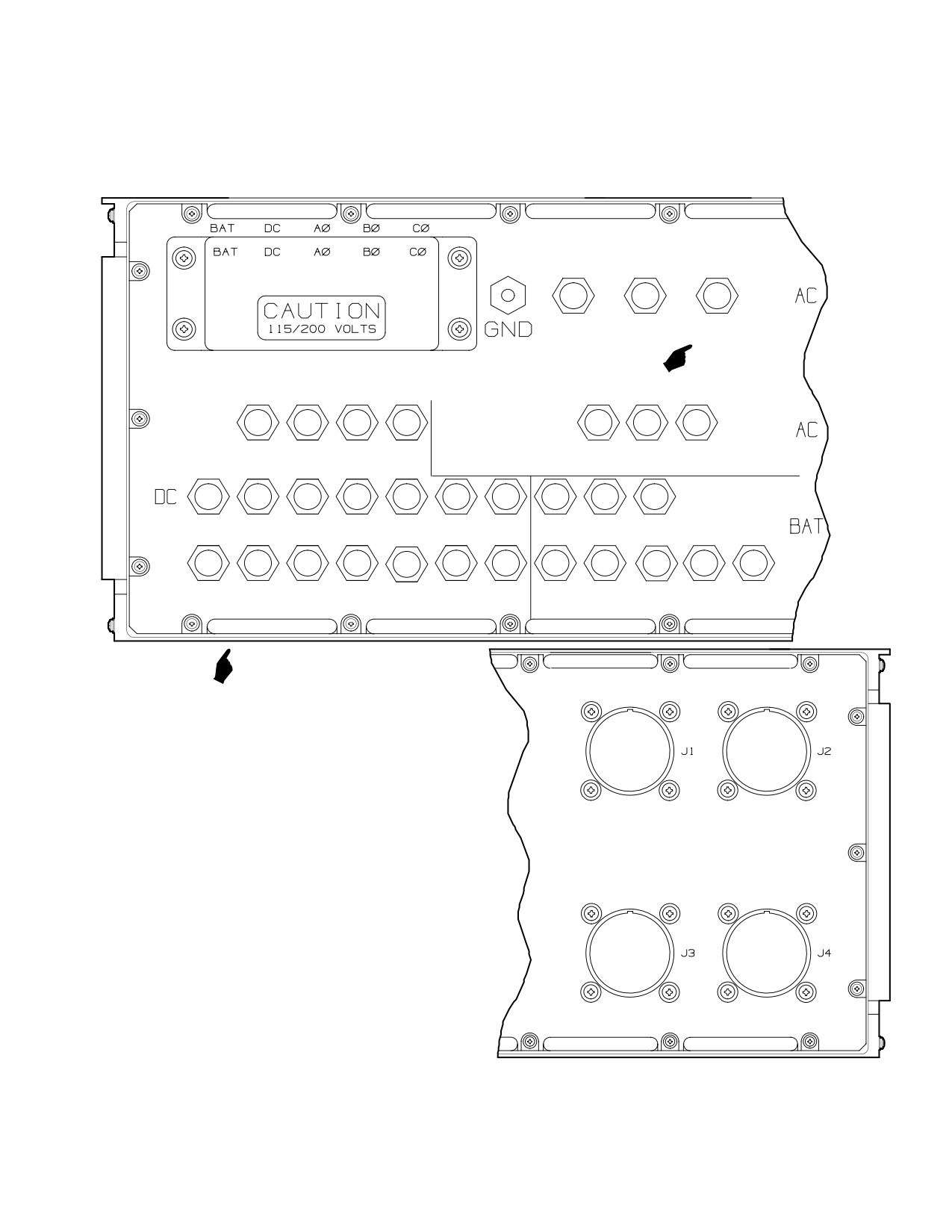
TM 1-1520-251-10
2.98.3
Electrical Load Center 1. ELC 1 receives
ary loads on the No. 1 busses. It also receives commands
115/200 Vac, 28 Vdc, and 24/28 Vdc input from HPSM 1.
from the system processors for positioning the remote
It contains the Circuit Breakers (CB) and remote con-
controlled switches. ELC 1 is located in the left forward
trolled switches necessary to supply the switched second-
EFAB. Figure 2-86 shows the CBs located on ELC 1.
P2
P1
IAFS
1760
ÔÔ
1760
FUEL
AC
AC
PUMP
TADS
LASER
CHAFF
RDR
SPARE
WP*SP 1&2
AIR DATA
STANDBY
WRN
ARM
WRN
/STAB SYN
SENSOR
RCVR
RCVR
(REFC)
HEATER
LW
LWT
LWT
P2
P2
P1
P1
ELCI
ENG1
ENG 1 BL
ROCKET
1760
1760
1760
1760
1760
1760
BAT
OIL
LOUVER
ARM
DC2
DC1
DC1
DC2
DC1
DC2
CONT
PRESS
ON/OFF
PNVS
IAFS
FUEL
LW
CANOPY
ENG1 A1
ELCI
FDMU
SPARE
ENG 1
ZEROIZE
FUEL
STANDBY
VALVES
PITOT
HEAT\
START BL
DC
(PROV)
ATS
PANEL
CRSFD1
CTRL
VLV/NOSE
HTR
DEFOG
CONT
VALVE
GBX HTR1
ELECTRICAL LOAD CENTER NO. 1
LBA2395A
Figure 2-86. ELECTRICAL LOAD CENTER NO 1 Circuit Breakers
Use or disclosure of this information is subject to the restriction(s) on the title page of this document.
Change 2
2-89
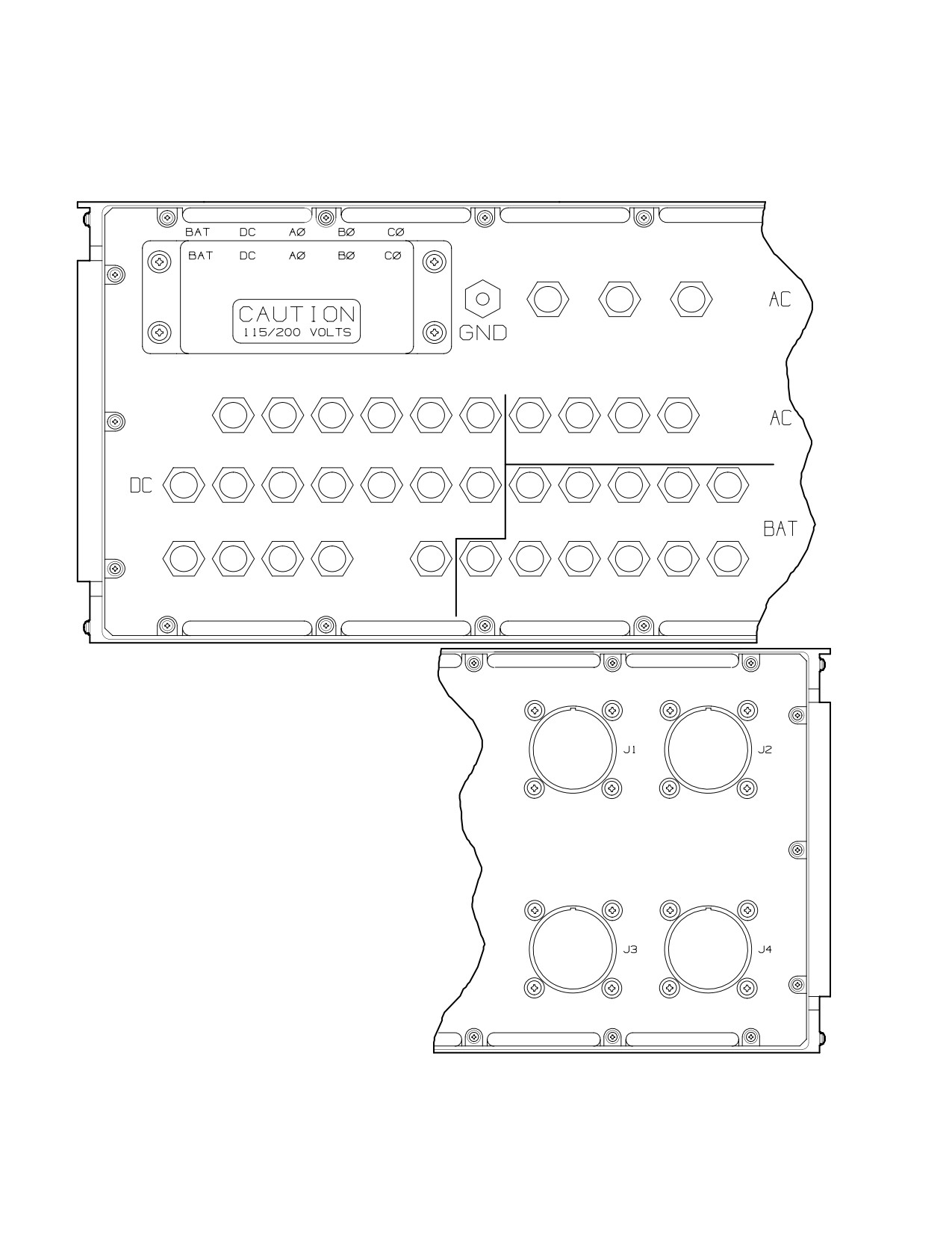
TM 1-1520-251-10
2.98.4
Electrical Load Center 2. ELC 2 receives
ary loads on the No. 2 busses. It also receives commands
115/200 Vac, 28 Vdc, and 24/28 Vdc input from HPSM 2.
from the system processors for positioning the remote
It contains the Circuit Breakers (CB) and remote con-
controlled switches. ELC 2 is located in the right forward
trolled switches necessary to supply the switched second-
EFAB. Figure 2-87 shows the CBs located on ELC 2.
P3
P4
SPARE
1760
1760
AC
AC
SPARE
IHADSS
IHADSS
RDR
DPLR
GUN
AWS
PLT FLT
PLT FLT
ICE
DEU PWR
SEU
ALTM
SENSOR
ARM
AC
CONT
CONT
PROBE
PWR
PWR
(REF B)
(REF A)
HEATER
RW
RWT
RWT
P3
P3
P4
P4
ELC2
ENG2 OIL
ENG2 BL
VIDEO
SPARE
ROCKET
1760
1760
1760
1760
1760
1760
BAT
PRESS
LOUVER
CONT
ARM
DC2
DC1
DC1
DC2
DC1
DC2
CONT
ON/OFF
PNL/PB1A
SPARE
ELC2
ICE SIG
RW
ENG2 A1/
APU ECU
XFER
ENG2
FUEL
APU FUEL
FUEL
DC
PROC/
PITOT
START BL
PWR/
AIR
ATS
BOOST
BOOST
CRSFD2
CONT
ASP SOV
HTR
VLV/NOSE
START
VALVE
AND SOV
GBX HTR2
ELECTRICAL LOAD CENTER NO. 2
LBA2397
Figure 2-87. ELECTRICAL LOAD CENTER NO 2 Circuit Breakers
Use or disclosure of this information is subject to the restriction(s) on the title page of this document.
2-90
TM 1-1520-251-10
2.99 BATTERY
the internal temperature of the battery drops below 10° C
the battery heater is activated. The internal heater is func-
tional between 10° C and - 40° C, therefore, an external
The battery subsystem consists of one 24 Vdc, 15 ampere
heater blanket is not required. The battery heater is pow-
hour, sealed cell, Fibrous Nickel Cadmium (FNC) battery
ered by the aircraft 28 Vdc bus via CBP 2.
and associated battery charger. Both the battery and bat-
tery charger are located in the right center EFAB. The bat-
2.101 DC ELECTRICAL SYSTEM
tery provides power during ground refueling, APU start-
ing, and engine starting. The battery also provides backup
power in the event of a loss of all other DC power (fig
2-83). In that event, the battery will supply the normal in
flight battery loads for a minimum of 12 minutes provided
Two regulated 28 Vdc, 350 amp TRUs are the primary DC
the battery is at least 80% charged. During normal opera-
power source, each capable of supplying managed power
tion the battery is isolated from the battery busses and is
to all DC loads. The TRUs convert AC input to 28 Vdc.
charged by the battery charger.
They are self monitoring for over temperature. TRU fail
status is displayed on the UFD/EUFD.
2.99.1 Battery Power Control. Battery power is con-
2.101.1 Total DC Circuit Load Support. Either TRU,
trolled by the MSTR IGN switch (fig 2-88) on the pilot
in conjunction with either generator, is capable of support-
POWER lever quadrant. The ignition key is not required to
ing the total DC bus load.
actuate the MSTR IGN switch. With the MSTR IGN switch
in the OFF position, power is still applied to the refuel pan-
2.101.2 DC BUS Interface with Battery Electrical Sys-
el. When the refuel switch on the refuel panel is turned
tem. Primary DC bus 1 and DC bus 2 provide 28 Vdc to
ON, the aircraft may be refueled without the need to turn
battery bus 1 and bus 2 through two diodes. These diodes
the MSTR IGN switch to the BATT position. When the
isolate the battery electrical system from DC bus load
MSTR IGN switch is placed in the BATT position, the bat-
when TRU electrical power has failed.
tery is connected to the battery busses unless the busses
are being supplied by the Transformer Rectifier Unit
2.101.3 TRU Failure. In the event of a TRU failure, a
(TRU) power. If the battery busses are being powered by
caution message will be annunciated on the MPD and the
the output of the TRU, the battery is isolated and placed in
UFD/EUFD. The failed DC bus system is then transferred
the charge mode. In the event that TRU power is lost, the
to the remaining operational DC bus system.
battery will automatically be connected to the battery
busses (fig 2-83).
2.102 AC ELECTRICAL SYSTEM
2.99.2
Battery Power Indications. Any time the
The AC generation subsytem consists of two 45 KVA, 3
battery charger fails, an advisory message is displayed on
Phase, 4 wire, 115/200 Vac, 400Hz, air cooled, brushless
the UFD/EUFD, and battery charging is terminated. If the
AC generators and two Generator Control Units (GCU).
charger detects a battery fault an advisory message is dis-
Each generator normally supplies its respective AC bus,
played on the UFD/EUFD, and battery charging is termi-
AC bus 1 or AC bus 2. In the event of a generator failure
nated.
the remaining generator has sufficient power to supply all
AC loads, without the need to load shed. Each generator
2.100 BATTERY CHARGER
control unit provides voltage regulation, control and
protection for its associated generator. Protection is pro-
The battery charger is normally powered by 115 Vac sup-
vided against undervoltage, overvoltage, underfrequency,
plied from CBP 2. The charger automatically maintains
over current/short circuit, and differential/feeder fault op-
the battery in a full state of charge. Additionally the battery
eration.
[
BLK 1
Aircraft
equipped with
charger monitors the battery temperature and state of
7-511B11019-11 and -13 GCUs, underfrequency protec-
health. If it detects a battery fault, it is reported to the sys-
tion is inhibited in flight and undervoltage protection is in-
tem processor for display on the UFD/EUFD. The charger
hibited during underfrequency operation. Aircraft
also monitors itself for a fault and if a fault is detected that
equipped with 7 - 511B11019 - 15 - 17, - 19 and - 21 GCUs,
is also reported to the system processor for display on the
underfrequency protection is functional in flight and
UFD/EUFD. In the event of a battery or battery charger
undervoltage protection is inhibited during underfre-
failure, battery charging is automatically terminated and
quency operation. ] [
BLK 2
Underfrequency protection
can not be restarted until the fault has cleared. Finally the
is functional in flight and undervoltage protection is inhib-
battery charger controls the battery internal heater. When
ited during underfrequency operation.]
Use or disclosure of this information is subject to the restriction(s) on the title page of this document.
Change 3
2-91
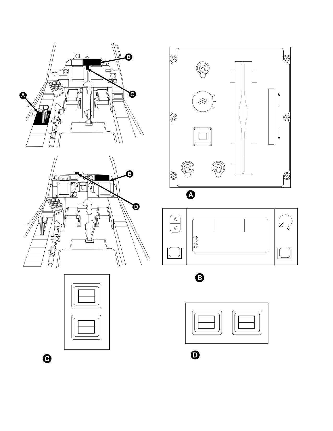
TM 1-1520-251-10
PILOT STATION
Ô
Ô
RTR BRK
POWER
Ô
Ô
OFF
Ô
Ô
BRK
LOCK
OUT
LOCK
FLY
MSTR IGN
INC
OFF
BATT
EXT
PWR
F
R
Ô
Ô
I
C
Ô
APU
T
Ô
ON
IDLE
DECR
ENG START
CPG STATION
START
OFF
OFF
Ô
Ô
IGN ORIDE
NO. 1
NO. 2
NO. 1
NO. 2
Ô
Ô
PILOT POWER LEVER QUADRANT
VIEW
BRT
WARNINGS
CAUTIONS
ADVISORIES
VH 139.500*
H8G65
L8
149.500
UH 240.075*
P3R56 C3 G
L2
249.500
J8L52 C5 H
45.550
LAST
RTS
F1 45.075*
B5Z23 C2
L4
69.525
F2 49.500*
1240
XP 1200 NORM B
10:56:01 L
UP FRONT DISPLAY (UFD)
MSTR
WARN
MSTR
MSTR
MSTR
WARN
CAUT
CAUT
CPG MASTER WARNING/
PILOT MASTER WARNING/
CAUTION PUSH BUTTONS
CAUTION PUSH BUTTONS
LBA0640A
Figure 2-88. Battery Control and Indicators
Use or disclosure of this information is subject to the restriction(s) on the title page of this document.
2-92
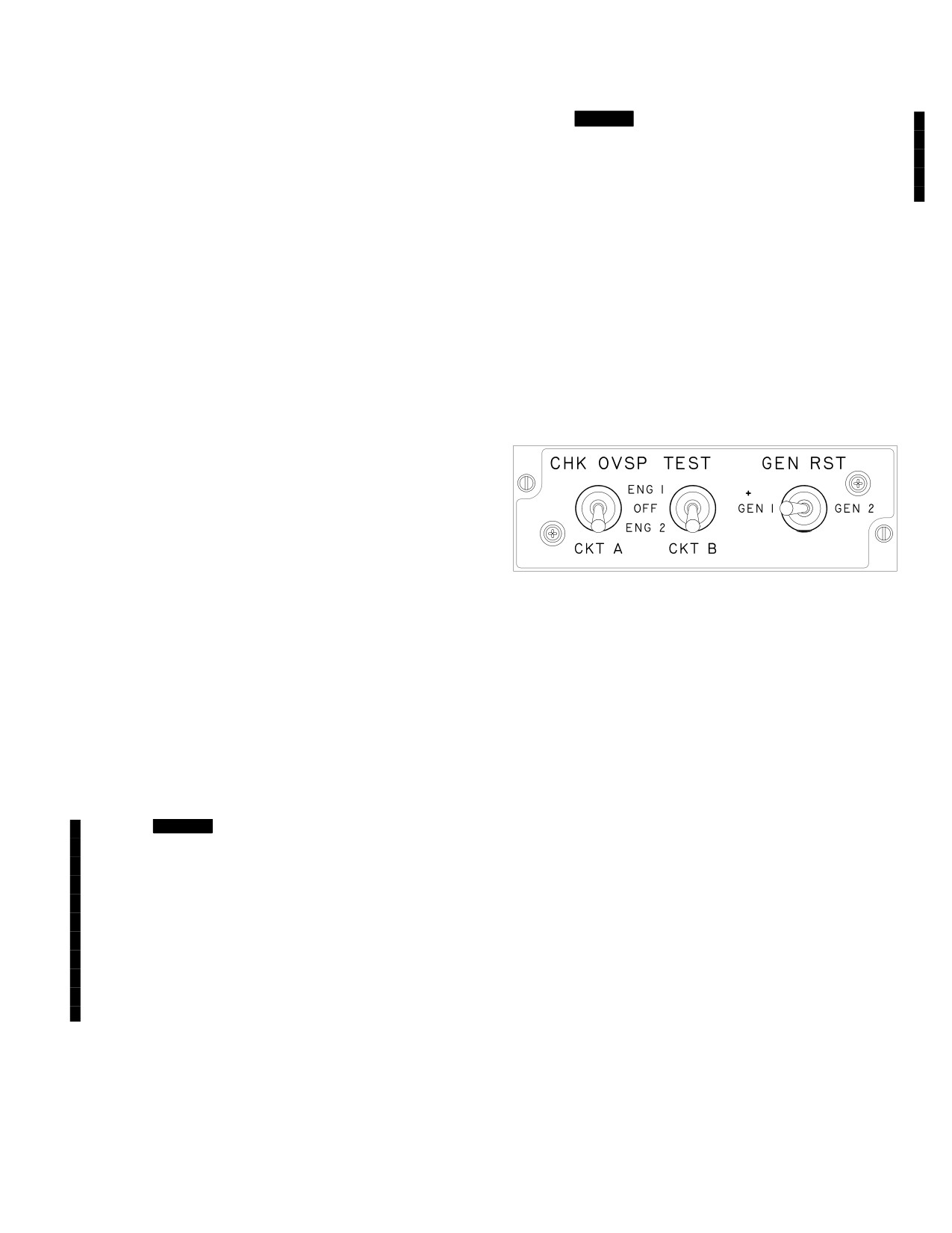
TM 1-1520-251-10
2.102.1 Generators. Each generator is capable of sup-
• [
BLK 2
Underfrequency (during ground opera-
plying power to all aircraft loads. Each generator is
tion, the AC generator output frequency drops to
equipped with a GCU which provides automatic start up
between 365 to 380 Hz for 1 to 3 seconds; during
and generator protection and fault detection for automatic
flight operation, AC generator frequency drops to
shutdown. If one generator fails, its load is automatically
306 Hz for 1 second).]
transferred to the other generator.
2.102.2 AC Power Indications. Anytime a generator is
a. Generator Drive. The generators are driven si-
failed, a caution message will be displayed on the UFD/
multaneously by the accessory gearbox. The accessory
EUFD and the MPD CAUTION page.
gearbox is driven by the APU or engines/main rotor.
2.102.3 AC Power Controls. Generator output is auto-
b. Generator Operation. During normal operation,
matically controlled by the GCU. In the event of an an-
each generator carries approximately 50% of the electri-
nunciation, the pilot may reset either generator with the
cal load. Each generator powers a three phase bus man-
GEN RST switch on the CHK OVSP TEST/GEN RST
aged by the EPMS. A bus interlock configuration prevents
panel (fig 2-89). A generator may be selected OFF
generators from operating in parallel or operating in paral-
through the SYS page.
lel with an external power source. Either generator is ca-
pable of supporting both AC busses.
c. Generator Electrical Output Manage-
ment. Generator output is managed by the associated
GCU, which regulates output voltage and provides protec-
tion against undervoltage, overvoltage, underfrequency,
over current/short circuit, and differential/feeder fault op-
eration. Underfrequency protection is inhibited in flight
and undervoltage protection is inhibited during underfre-
LBA0020
quency operation. The GCU connects its associated gen-
erator to the appropriate AC primary bus. The GCU dis-
Figure 2-89. Check Overspeed Test/Generator
connects and de-energizes its generator under the
Reset Panel
following adverse operating conditions:
• Overcurrent/short circuit
2.103 EXTERNAL/GROUND POWER
• Overvoltage (the AC generator output voltage is
greater than 125 Vac).
Ground power is applied to the helicopter by connecting
• Undervoltage (the AC generator output voltage
the power cable from the Aviation Ground Power Unit
drops below 100 Vac for longer than 200 ±50
(AGPU) to the external power receptacle located in the
milliseconds).
right hand aft fuselage (refer to Section XV). Ground pow-
er supplies power to all aircraft loads.
• [
BLK 1
Aircraft equipped with 7- 511B11019 - 11
and - 13 GCUs, underfrequency (during ground
2.103.1 External/Ground Power Controls. When the
operation, the AC generator output frequency
MSTR IGN switch is in the EXT power position, the exter-
drops to between 365 to 380 Hz for 1 to 3
nal power monitor automatically controls the application of
seconds).
power to the helicopter and monitors for degraded power
Aircraft equipped with 7 - 511B11019 - 15 - 17, - 19
supply.
and - 21 GCUs underfrequency (during ground
operation, the AC generator output frequency
drops to between 365 to 380 Hz for 1 to 3 seconds;
2.103.2 External/Ground Power Indications. The
during flight operation, AC generator frequency
UFD/EUFD will display an advisory when the external
drops to 306 Hz for 1 second). ]
power access door is open.
Use or disclosure of this information is subject to the restriction(s) on the title page of this document.
Change 3
2-93
TM 1-1520-251-10
Section XII. AUXILIARY POWER UNIT (APU)
2.104
INTRODUCTION
also provides, directly, pressurized air for the operation of
helicopter systems anytime the APU is ON (whether or not
the main engines are driving the transmission accessory
WARNING
section). The APU provides the means of engine starting
without the need for an AGPU. It is located just inboard of
• To prevent an accidental APU start,
the APU ECU PWR/START circuit
the right engine nacelle in the aft equipment bay. The APU
breaker located on the ELECTRICAL
consists of a gearbox, a compressor, and a turbine sec-
LOAD CENTER NO. 2 in the right hand
tion, together with associated fuel, lubrication, and electri-
EFAB shall be out when battery or ex-
cal systems.
ternal power is connected to the heli-
copter and unqualified personnel are
in or around the pilots crew station.
• The APU ECU testing performed
2.104.1 Fuel System. The aft fuel cell provides all fuel
shows that certain transmitters can
for APU operation and is discussed in more detail in Sec-
preclude the APU from being started
tion IV of this chapter. The APU fuel control automatically
or will cause it to be shut down. Addi-
regulates fuel flow. The APU burns approximately 175 lb
tionally, it is possible that uncomman-
of fuel per hour.
ded overspeeds could occur without
overspeed protection. The aircrew
should exercise caution when starting
the APU in any location where the APU
2.104.2 Lubrication System. The APU has a self con-
has not been previously operated, es-
tained oil system. An oil filler cap is located on the left side
pecially in the vicinity of high powered
of the unit. Oil cooling is provided by airflow over cooling
transmitters.
fins at the compressor inlet. The oil level sight gage is lo-
cated on the right side and is an integral part of the oil
The APU (fig 2-90) indirectly provides hydraulic pressure
and electrical power for the operation of helicopter sys-
sump. The sight gage can be inspected through a door in
tems whether the engines are operating or not. The APU
the bottom of the right engine nacelle.
Use or disclosure of this information is subject to the restriction(s) on the title page of this document.
2-94
Change 2
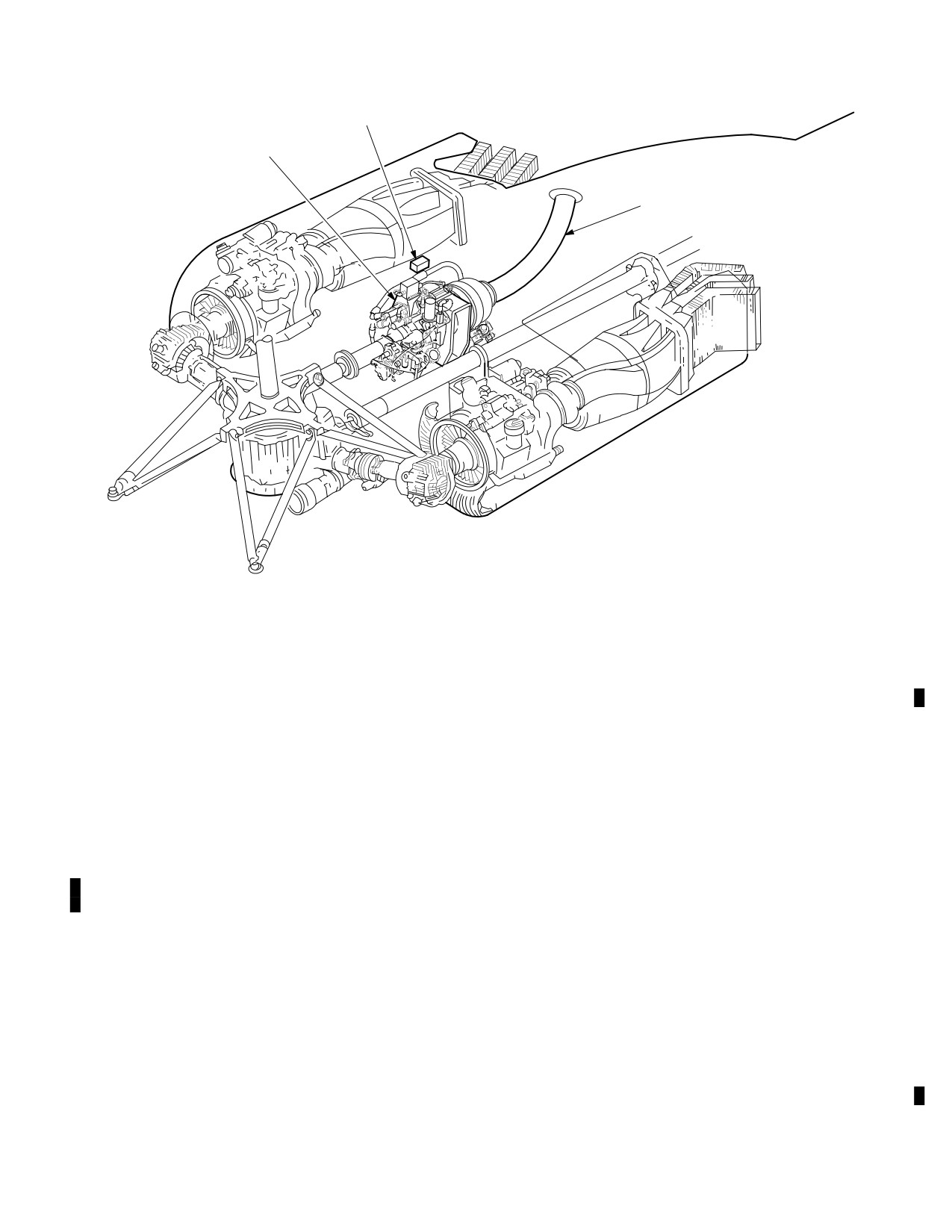
TM 1-1520-251-10
APU ELECTRONIC CONTROL UNIT
APU
APU EXHAUST DUCT
LBA0391
Figure 2-90.
APU Location
2.104.3 Electrical System. The APU electrical system re-
OFF. The ECU also transmits the shutdown signal auto-
quires DC power. This power is normally delivered by the he-
matically for fault detection of any of the monitored func-
licopter battery when the MSTR IGN switch is set to BATT.
tions. An advisory is sent from the low oil pressure switch
when automatic shutdown occurs. The PTO clutch actua-
2.104.4 APU Control Switch. The APU control switch is a
tion is also controlled by the APU ECU. Normally, PTO
momentary button switch located on the pilot POWER lever
clutch engagement occurs at 60% APU speed if the main
quadrant (fig 2-88). This switch applies dc power to energize
transmission temperature is above 0 °F; however, if the
the APU boost pump, open the APU fuel shutoff valve, and
main transmission temperature is below 0 °F, it will en-
sends a signal to the APU ECU to commence the start se-
gage at 95% APU speed.
quence. The APU momentary button switch turns the APU
ON and OFF, and has a hinged cover to prevent inadvertent
2.104.6 Main Transmission Low Oil Temperature Sen-
actuation. When the APU is turned ON and the APU speed
sor. The main transmission low oil temperature sensor
reaches 95%, the ON legend in the button illuminates and an
provides transmission oil temperature information to the
advisory is displayed on the UFD/EUFD.
system processor for cold start of the APU.
2.104.5 APU Electronic Control Unit (ECU). The APU
2.104.7 Utility Hydraulic Accumulator. The accumu-
ECU provides for automatic start and operation of the
lator, located on the deck of the aft equipment bay below
APU and Power Takeoff clutch (PTO) engagement. The
the APU, provides hydraulic pressure to the APU hydrau-
start valve opens when the APU switch is pressed to ON
lic starter through a solenoid operated hydraulic start
and closes automatically at 60% APU speed. The ECU
valve. The utility hydraulic accumulator is discussed in
monitors the APU for loss of thermocouple, overtempera-
more detail in Section VI of this chapter.
ture, overspeed, overcurrent, low oil pressure, percent
rpm, and exhaust gas temperature. The APU ECU trans-
2.104.8 APU Advisories. The APU advisories are dis-
mits a shutdown signal to the APU whenever the APU but-
played on the UFD/EUFD and MPD and are listed in Table
ton switch on the pilot POWER lever quadrant is set to
2-15.
Use or disclosure of this information is subject to the restriction(s) on the title page of this document.
Change 2
2-95
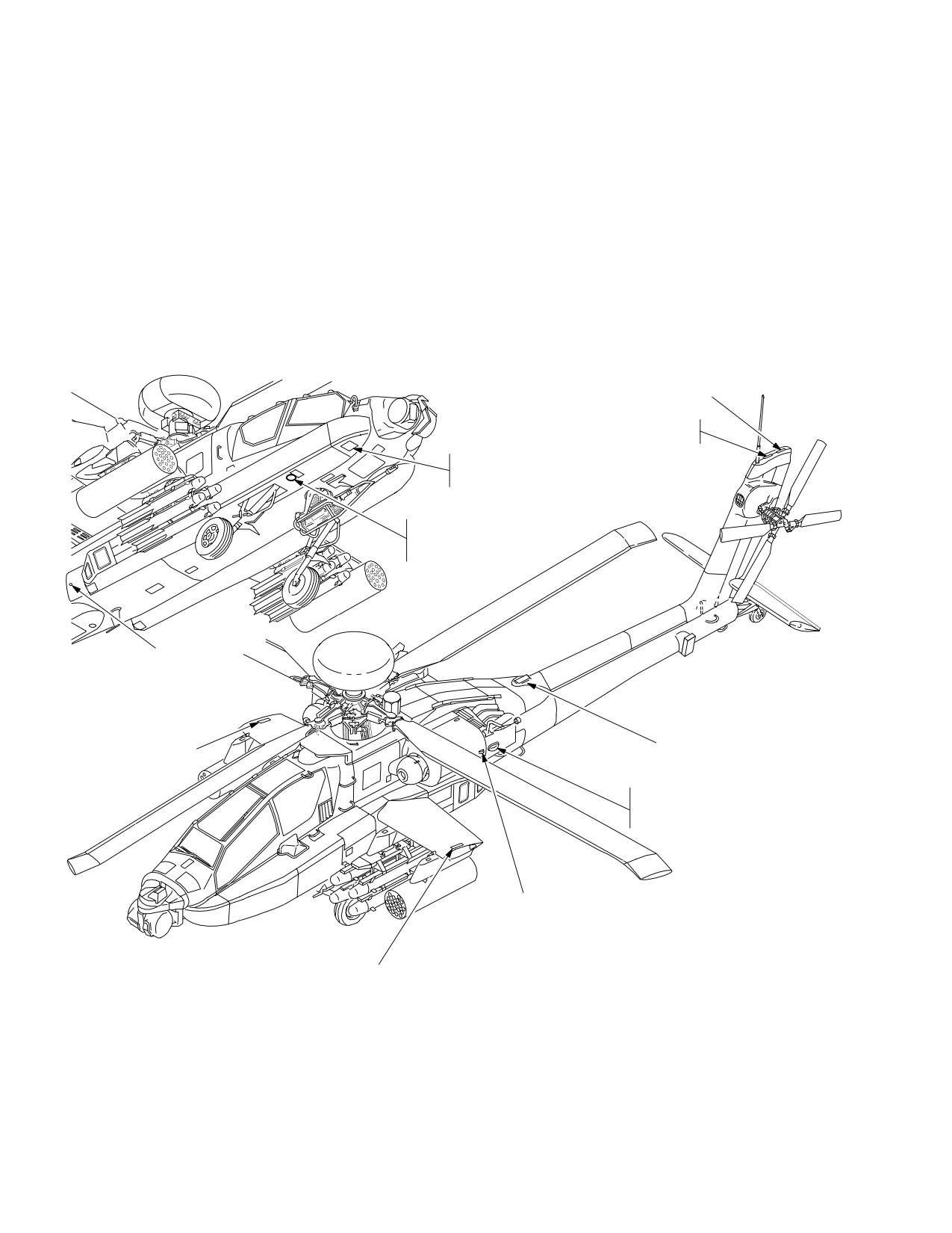
TM 1-1520-251-10
Section XIII. LIGHTING
2.105 LIGHTING EQUIPMENT
The aircraft lighting system consists of exterior and interi-
or lighting and their associated controls. The main func-
NOTE
tion of the aircraft exterior lighting is to provide visual in-
dications to other aircraft for navigation and safety
The search/landing light, crew station flood
reasons. The aircraft interior lighting provides crewmem-
lights, signal lights, and utility lights are the
bers with Night Vision Goggle (NVG) compatible lighting.
only lights available under battery power.
2.106 EXTERIOR LIGHTING EQUIPMENT
Exterior lighting equipment (fig 2-91) consists of formation
lights, navigation lights, anticollision lights, a search/land-
ing light, and an inspection and maintenance light.
NAVIGATION
LIGHT (WHITE)
FORMATION
LIGHT (GREEN)
FWD INSPECTION AND
MAINTENANCE LIGHT
RECEPTACLE
SEARCH/LANDING
LIGHT (WHITE)
RETRACTED POSITION
FWD INSPECTION AND
MAINTENANCE LIGHT
RECEPTACLE
(INSIDE AVIONICS BAY)
FORMATION LIGHT (GREEN)
FORMATION LIGHT (GREEN)
ANTICOLLISION LIGHT
(RED OR WHITE)
(TYPICAL BOTH SIDES)
NAVIGATION LIGHT
(LEFT SIDE RED,
RIGHT SIDE GREEN)
FORMATION LIGHT (GREEN)
LBA0545
Figure 2-91. Exterior Lighting Equipment
Use or disclosure of this information is subject to the restriction(s) on the title page of this document.
2-96
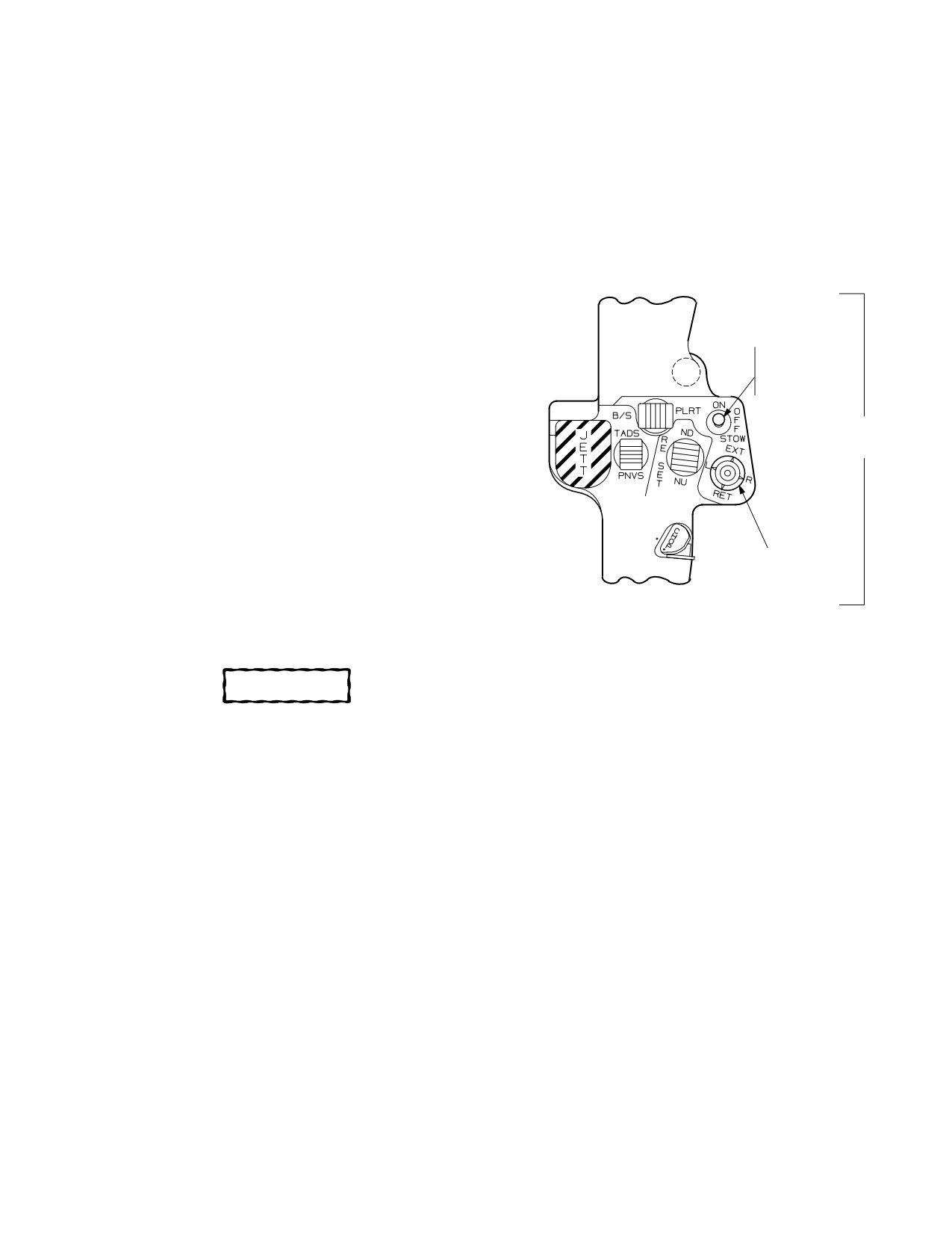
TM 1-1520-251-10
2.106.1 Formation Lights. The green formation lights
in a fairing under the forward section of the right Extended
provide visual orientation information regarding position of
Forward Avionics Bay (EFAB), just forward of the landing
the helicopter to adjacent aircraft in formation flight. They
gear attachment. The searchlight control switches (fig
are located on the upper surface of each wing, the upper
2-92) are located on the flight control grip of the collective
centerline of the aft fuselage, and on the upper surface of
control stick. Setting the ON/OFF/STOW switch to ON
the vertical stabilizer. The formation (FORM) lights rotary
supplies 28 vdc to the searchlight. The searchlight posi-
control knob on the pilot Exterior/Interior Lighting (EXT LT/
tion switch is a four position thumbforce control switch
INTR LT) panel varies the intensity of the formation lights
used to manually control searchlight motion.
from OFF to BRT (bright). For description and operation
of pilot and CPG lighting control panels, refer to paragraph
2.107.
2.106.2 Navigation Lights. The navigation lights indi-
SEARCH/LANDING
LIGHT
cate aircraft position and direction to other aircraft during
ON/OFF/STOW
flight. One green light is located on the right engine na-
SWITCH
celle and one red light is located on the left engine nacelle.
One white aft navigation light is located on the top aft side
FLIGHT
CONTROL
of the vertical stabilizer. The navigation (NAV) lights
GRIP
switch on the pilot EXT LT/INT LT panel has three posi-
tions, BRT, OFF, and DIM.
2.106.3 Anti-collision Lights. The anti-collision lights
provide a visual anti-collision warning during all phases of
SEARCH/LANDING
flight. High intensity red and white anti-collision strobe
LIGHT
POSITION
lights are located on each engine nacelle. The anti-colli-
SWITCH
sion (ANTI COL) lights switch on the pilot EXT LT/INT LT
LBA0480
panel has three positions: WHT, OFF and RED.
Figure 2-92. Search/Landing Light Control
CAUTION
Switches
• The searchlight can reach tempera-
2.106.5 Inspection/Maintenance Light. The inspec-
tures capable of igniting combustible/
tion/maintenance light is stored in the left equipment stow-
flammable materials. Do not land in
age compartment. Two plug-in electrical receptacle loca-
areas such as high grassy meadows
tions and the light’s 50 ft long cord facilitates inspection
with the searchlight ON.
and maintenance at all points on the helicopter. One re-
• Burning of the aircraft skin is possible
ceptacle is located adjacent to the CPG station on the un-
if the searchlight is over - extended.
derside of the right EFAB, forward of the searchlight. The
second receptacle is located in the right aft avionics bay.
• R/H EFAB door should not be left open
Operation of the inspection/maintenance light is con-
with the searchlight on.
trolled by an OFF/BRT rheostat switch which is integral
with the light.
NOTE
2.107 LIGHTING CONTROLS
Searchlight motion is inhibited for 60 sec-
onds after the ON/OFF/STOW switch is
Aircraft exterior lighting (excluding the searchlight) is con-
placed in the STOW position.
trolled via the EXT LT section of the pilot EXT LT/INTR LT
panel (fig 2-93). Aircraft interior lighting can be controlled
2.106.4 Search/landing Light. The retractable search-
independently for each cockpit by use of the INTR LT sec-
light provides omnidirectional search and landing light
tion of the pilot EXT LT/INTR LT panel or the CPG INTR
during low visibility conditions. The searchlight is located
LT panel.
Use or disclosure of this information is subject to the restriction(s) on the title page of this document.
2-97
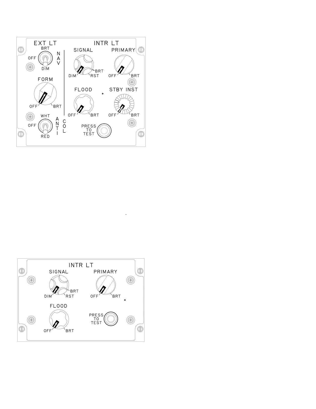
TM 1-1520-251-10
NOTE
The Lighting Distribution Unit in the pilot
crewstation contains variable resistors
ÑÑÑ
ÑÑÑ
(available to maintenance personnel) to al-
low balancing of individual panels in the
ÑÑÑ
ÑÑÑ
standby instruments lighting system for uni-
ÑÑÑ ÑÑÑ
form intensity within the crewstation
ÑÑÑ
throughout the STBY INST control dimming
ÑÑÑ
Ñ
Ñ
range.
ÑÑÑ
ÑÑÑ
ÑÑÑ
2.108 INTERIOR LIGHTING EQUIPMENT
ÑÑ
ÑÑÑ
ÑÑÑ
ÑÑÑ ÑÑ
The interior lighting system includes four subsystems
powered by the Lighting System Controller: primary, sec-
ondary/emergency, signal, and standby instrument light-
ing. Each cockpit also has one utility light.
LBA0025
2.108.1 Primary Lighting. Primary lighting consists of
integrally illuminated lightplates, display bezels and key-
pads. The PRIMARY variable resistor rotary control al-
lows for continuous adjustment of the crewstation primary
lighting system brightness from OFF to BRT. Turning the
Figure 2-93.
Pilot EXT LT/INTR LT Panel
PRIMARY variable resistor from OFF towards BRT in-
forms the Lighting System Controller that the cockpit is in
a “night” condition and allows for the SIGNAL RST posi-
tion to function for resetting to a dim mode. The FLOOD
2.107.1 INTR LT Panel. The INTR LT section of the pi-
control must be OFF or less than the midpoint of its range
lot panel controls the lighting in the pilot’s station and con-
to allow SIGNAL RST. The PRIMARY lights control is on
sists of four rotary control knobs and a PRESS-TO-TEST
the pilot EXT LT/INTR LT panel and on the CPG INTR LT
button. The CPG INTR LT panel (fig 2-94) controls the
panel.
lighting in the CPG’s station and consists of three rotary
control knobs and a PRESS-TO-TEST button.
2.108.2 Secondary/Emergency Lighting. Secondary/
emergency lighting consists of floodlights to provide crew
compartment illumination and is powered by the battery
bus as an alternate to primary lighting. The FLOOD vari-
able resistor rotary control allows for continuous adjust-
ment of the floodlighting system brightness from OFF to
ÑÑÑ
ÑÑ
BRT. Turning the FLOOD control clockwise past the mid-
point of the control range informs the Lighting System
ÑÑÑ
ÑÑÑ
Controller that the cockpit is in a “bright” condition and re-
ÑÑÑ
ÑÑÑ
verts the SIGNAL lights to BRT. Turning the FLOOD con-
trol counterclockwise past the midpoint of the control
range allows for the SIGNAL lights to reset to a dim mode.
The FLOOD lights control is on the pilot EXT LT/INTR LT
ÑÑÑ
panel and on the CPG INTR LT panel.
ÑÑÑ
ÑÑÑ
2.108.3
Standby Instrument Lighting. Standby
instrument lighting consists of integral illumination of the
LBA0026
four standby flight instruments in the pilot station. The
STBY INST variable resistor rotary control allows for con-
tinuous adjustment of the standby instruments lighting
system brightness from OFF to BRT. The STBY INST
Figure 2-94. CPG INTR LT Panel
lights control is on the pilot EXT LT/INTR LT panel.
Use or disclosure of this information is subject to the restriction(s) on the title page of this document.
2-98
TM 1-1520-251-10
2.108.4 Signal Lighting. Signal lighting includes warn-
manually turn the control to RST for night conditions.
ing, caution, and advisory indicators/switches. The SIG-
Turning the FLOOD control clockwise past the midpoint of
NAL variable resistor rotary control allows for continuous
the control range informs the Lighting System Controller
adjustment from DIM to BRT for the SIGNAL lighting. The
that the cockpit is in a “bright” condition and reverts the
rotary control knob for SIGNAL lighting includes a RST
SIGNAL lights to the bright mode. Turning the FLOOD
position to allow for reset to dim mode for night conditions.
control counterclockwise past the midpoint of the control
The warning lights have a fixed daytime brightness (28
range allows for the SIGNAL lights to reset to a dim mode.
vdc) and a fixed nighttime brightness (14 vdc). The cau-
The PRESS TO TEST button allows all SIGNAL lighting
tion and advisory lights have a fixed daytime brightness
lamps to be tested at once. The SIGNAL lights control and
(28 vdc) and a variable nighttime brightness (14 vdc
PRESS TO TEST button are on the pilot EXT LT/INTR LT
max.). The SIGNAL variable resistor controls the signal
panel and on the CPG INTR LT panel.
lighting brightness for the advisory lights from BRT to
DIM, but does not extinguish the lights. Initial aircraft pow-
2.108.5 Utility Light. The utility light is stowed (via a
er-up sets the SIGNAL lighting to full daytime brightness.
bayonet base) in the left side of each crewstation. The
If the PRIMARY lights control is ON, and the FLOOD light-
hand-held light has a coiled cord and is powered by the
ing control is less than the midpoint position, then turning
battery bus. The utility light has a built-in variable rheostat
the SIGNAL control clockwise to the momentary RST
control for continuous adjustment of the light from OFF to
position results in reset to the dim mode for night condi-
BRT, and a press-to-hold BRT button. The beam can be
tions. In the event of a power interrupt, the signal lighting
adjusted from SPOT to FLOOD. The color of the illumina-
reverts to the daytime brightness; the crewmember must
tion can be adjusted to WHITE or NVG GREEN.
Use or disclosure of this information is subject to the restriction(s) on the title page of this document.
2-99
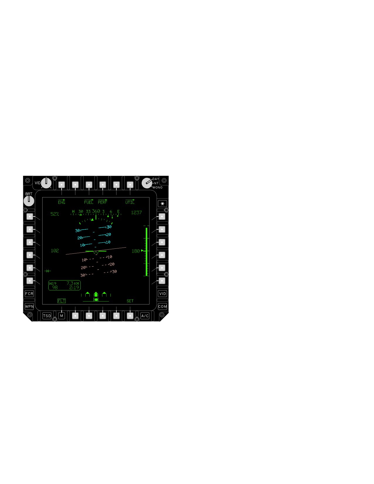
TM 1-1520-251-10
Section XIV. FLIGHT INSTRUMENTS
2.109 INTRODUCTION
• T4
PERF (Performance) page button
• T6
A/C UTIL (Utility) page button
Instruments discussed in this section are, for the most
part, those that directly measure flight performance. Flight
• L5
-W- (Waterline) button
instruments are available on the IHADSS and the MPD
• B6
FLT SET button
FLT page. The CPG can present flight symbology, HOD/
HDD displays, and video displays on the ORT.
2.110.1 MPD FLT Page Buttons. The FLT page (figs
2-95 and 2-96) provides the following button selections:
2.110 MPD FLT PAGE
a. ENG Page Button. Pressing the ENG page but-
The FLT page (fig 2-95) presents flight instrument
ton presents the Engine instrument page.
symbology required for flight from the MPD. The majority
of the buttons and some of the graphics are presented
b. FLT Page Button (On second level only). Press-
only when the FLT SET button is selected,
ing (deselecting) the FLT page button returns the MPD to
the top-level format.
c. FUEL Page Button. Pressing the FUEL page
button presents the Fuel page.
d. PERF Page Button. Pressing the PERF page
button presents the Performance page.
e. A/C UTIL Page Button. Pressing the A/C UTIL
button presents the Aircraft Utility page.
f.
-W- Button. The -W- button allows the crew to
align the attitude indicator and HMD horizon line to the
waterline symbol in the pitch axis. The word BIAS is pres-
ented below the waterline button when a bias has been
applied using the up or down bias buttons. Deselecting
the - W - button clears any manually applied bias from the
attitude indicator and HMD horizon line.
g. FLT SET button. Selection of the FLT SET but-
ton presents the control buttons necessary to set or enter
LBA0580A
data on the FLT page. Deselecting the FLT SET button
blanks these control buttons and additional graphics, and
Figure 2-95. FLT Page
returns the format to the FLT page.
• T1
ENG (Engine) page button
2.110.2 MPD FLT Page graphics. The FLT Page pro-
• T3
FUEL page button
vides the following graphics (fig 2-96):
Use or disclosure of this information is subject to the restriction(s) on the title page of this document.
2-100
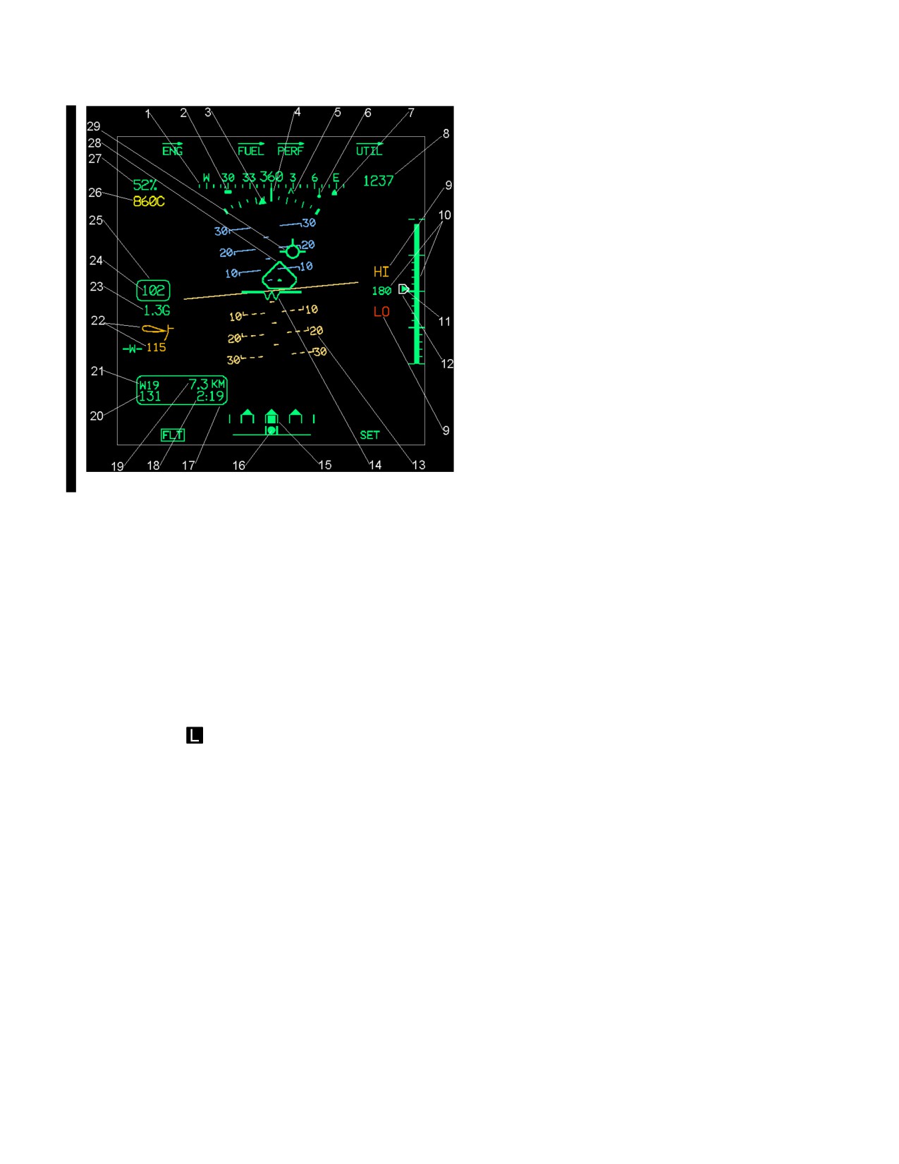
TM 1-1520-251-10
4. Lubber Line. The lubber line is aligned to the
centerline of the aircraft. It is the reference for both heading
and angle of bank.
5. Command or Bobup Heading. The com-
mand heading chevron symbol along the bottom of the
magnetic heading scale indicates the heading to the next
navigation waypoint selected through the navigation sub-
system. The symbol is presented when there is a valid next
waypoint and the heading scale is presented. Upon selec-
tion of the cyclic symbol select bobup mode, the symbol
represents the heading at the initiation of the bobup sym-
bol. The symbol remains at the bobup heading until the bo-
bup mode is disengaged or the heading becomes invalid.
6. ADF Bearing. The ADF bearing is presented
along the bottom of the magnetic heading scale, represent-
ing the instantaneous bearing to the tuned ADF Non - Di-
rectional Beacon (NDB). It is displayed only when a valid
bearing signal is received by the ADF system and the
heading scale is presented.
LBA5199A
7. Alternate
(Pilot or CPG) Sensor Bear-
ing. The alternate crewmembers sensor bearing is pres-
ented as a triangle along the bottom of the heading scale. It
Figure 2-96. FLT Page Symbols
is only presented when the heading scale is presented and
the opposite crewmembers sight is valid. This allows one
crewmember to see the other crewmember’s selected sen-
1.
Heading Scale. The heading scale is cen-
sor’s line of sight azimuth. The symbol is not presented in a
tered in the top area of the page. The moving scale has a
crew station when the other crewmembers selected sight is
total range of 360°. It displays an instantaneous 180° in 10°
FCR.
increments, and the major cardinal points are labeled N, S,
E, and W. Current magnetic heading is located in the center
8. Barometric or Inertial Altitude. Barometric
of the heading scale as a 3 digit data field. The heading
altitude is presented in feet in the upper right area of the
scale is presented when the EGI has determined its true
page. The total range of barometric altitude is from - 2300
heading, and has a position for determining magnetic vari-
to 20,000 ft, in 10 ft increments. Barometric altitude is not
ance.
presented when the ADS has identified internal continuous
BIT faults, when there is no last stored altimeter settings, or
2. FCR
Centerline Bearing. The FCR cent-
when barometric pressure data is out of valid range. The
erline bearing is displayed along the bottom of the magnet-
inertial altitude (calculated MSL altitude) is WHITE in color
ic heading scale. It represents the azimuth of the current
and presented in feet with the WHITE text “INRTL” beneath
FCR scan centerline
(or line of bearing) when the
it when barometric altitude is not available, or when the EGI
centerline is within the displayed portion of the heading
has identified internal continuous BIT faults, and when in-
scale. The FCR centerline bearing is presented when the
heading scale is presented and the requirements for pre-
ertial altitude data is valid. Inertial altitude presented is the
calculated MSL altitude using inertial altitude information.
sentation of the FCR footprint on the TSD Page are met.
The total range of inertial altitude is from - 2300 to 20,000 ft,
3. Bank Angle. The bank angle indicator pro-
in 10 ft increments. The System Processor computes the
vides an analog indication of the aircraft’s current bank
displayed INRTL MSL altitude, using the Inertial altitude
angle in degrees. The bank angle indicator consists of a
and present position information from the primary INU.
fixed curved tape presenting a minimum of 30° to the left
Maximum allowable error is 70 ft.
and 30° to the right of the 0° bank in 5° increments. The
bank angle triangle is aligned and fixed to the roll move-
9. Radar Altitude HI and LO. The radar altitude
ment of the attitude indicator. As the bank angle increases,
HI and LO indicators are displayed just above and below
the bank angle tick marks expand to show a larger portion
the radar altitude digital readout. The YELLOW HI and
of the compass rose. When the angle of bank exceeds
RED LO indications can be set to present at 1 to 1428 ft. If
”20°, the entire symbol is shown WHITE in color. The bank
the HI or LO indications are set to 0, they are not presented
angle is presented if the attitude indicator is presented.
to the crew.
Use or disclosure of this information is subject to the restriction(s) on the title page of this document.
Change 4
2-101