HELICOPTER, ATTACK, AH-64D LONGBOW APACHE. TECHNICAL MANUAL (2002) - page 1
*TM 1-1520-251-10
TECHNICAL MANUAL
WARNING DATA
OPERATOR’s MANUAL
TABLE OF CONTENTS
FOR
HELICOPTER, ATTACK,
INTRODUCTION
AH-64D
AIRCRAFT AND SYSTEMS
DESCRIPTION AND OPERATION
LONGBOW APACHE
AVIONICS
WARNING - This document contains technical data whose export is
restricted by the Arms Export Control Act (Title 22, U.S.C., Sec. 2751
et seq.) or the Export Administration Act of 1979, as amended, Title
MISSION EQUIPMENT
50, U.S.C., App. 240 - 1 et seq. Violation of these export laws are
subject to severe criminal penalties. Disseminate in accordance with
OPERATING LIMITS AND
provisions of DoD Directive 5230.25.
RESTRICTIONS
DISTRIBUTION STATEMENT D - Distribution authorized to
Department of Defense and DoD contractors only due to critical
WEIGHT/BALANCE AND LOADING
technology. This determination was made on 26 June 2000. Other
requests for this document shall be referred to Commander, US Army
Aviation and Missile Command, ATTN: SFAE-AV-AAH-ATH,
PERFORMANCE DATA
Redstone Arsenal, AL 35898 - 5000.
DESTRUCTION NOTICE - Destroy by any method that will prevent
NORMAL PROCEDURES
disclosure of contents or reconstruction of the document.
TECHNICAL DATA (INCLUDING DRAWINGS): — Furnished to the
EMERGENCY PROCEDURES
U.S. Government with Unlimited Rights as defined by DFARS
252.227 - 7013 (NOV 1995), which takes precedence over any other
restrictive markings.
REFERENCES
Furnished to all others with restrictions. This document includes
MDHS proprietary rights. Recipient agrees not to reproduce, disclose
to others, or transfer to other documents all or any part of this docu-
ABBREVIATIONS AND TERMS
ment for any purpose except as authorized in writing by MDHS. If the
recipient has rightfully received this document from the U.S. Govern-
TWO LETTER IDENTIFIERS
ment, this paragraph does not apply.
AND SYMBOLS
Copyright unpublished 1998. All rights reserved under the copyright
laws by MDHS. A copyright license is granted to the U.S. Govern-
ment under DFARS 252.227 - 7013 (NOV 1995).
RFI DETECTED, FCR SYMBOLS
ALPHABETICAL INDEX
* This manual supercedes TM 1-1520-251-10, dated
15 December 1998, including all changes.
HEADQUARTERS, DEPARTMENT OF THE ARMY
29 MARCH 2002
TM 1-1520-251-10
WARNING
Personnel performing operations, procedures, and practices which are included
or implied in this technical manual shall observe the following warnings.
Disregard of these warnings and precautionary information can cause serious
injury or loss of life.
WARNING
AVIATION LIFE SUPPORT EQUIPMENT
Aviation life support equipment shall be utilized in accordance with AR 95 - 1 and
FM 1 - 302. Failure to do so may result in personal injury or loss of life.
WARNING
BATTERY ELECTROLYTE
Battery electrolyte is harmful to the skin and clothing. Neutralize any spilled
electrolyte by thoroughly flushing contacted area with water.
WARNING
CANOPY JETTISON
Canopy jettison safety pins shall be installed in pilot, copilot/gunner, and
external firing mechanisms when the helicopter is on the ground. The canopy
jettison system is manually operated. The canopy can be jettisoned when no
electrical power is on the helicopter. Pilot and copilot/gunner safety pins shall be
removed before starting engines. Safety pins shall be installed during engine
shutdown check. Debris may be expelled 50 feet outward when system is
actuated. Pilot and copilot/gunner helmet visor should be down to prevent eye
injury.
WARNING
CARBON MONOXIDE
When smoke, suspected carbon monoxide fumes, or symptoms of anoxia exist,
the crew should immediately ventilate the cockpit.
WARNING
ELECTROMAGNETIC INTERFERENCE (EMI)
No electrical/electronic devices of any sort, other than those described in this
manual or appropriate maintenance manuals, are to be operated by crew
members during operation of this helicopter. The aircraft may experience
equipment performance anomalies when flying in the vicinity of High Intensity
Radio Transmission Areas (HIRTAs); accordingly, aircraft flights, whether day or
night, shall use night stand - off distances in accordance with HIRTA messages.
Even when in compliance with the above paragraph, erratic behavior of these
systems (communication, navigation, display and weapons) may occur when
operating in and around high - powered radio and radar transmitters.
Use or disclosure of this information is subject to the restriction(s) on the title page of this document.
Change 2
a
TM 1-1520-251-10
WARNING
FIRE EXTINGUISHER
Exposure to high concentrations of extinguishing agent or decomposition
products should be avoided. The liquid should not be allowed to contact the
skin; it may cause frostbite or low - temperature burns.
WARNING
GROUND OPERATION
Engines will be started and operated only by authorized personnel. Reference
AR 95 - 1 and AR 95 - 13.
WARNING
HANDLING FUEL, OIL, AND HYDRAULIC FLUIDS
Turbine and lubricating oils contain additives which are poisonous and readily
absorbed through the skin. Do not allow them to remain on skin longer than
necessary. Prolonged contact may cause skin rash. Prolonged contact with
hydraulic fluid may cause burns. Refer to FM 10 - 68 and FM 10 - 69 when handling
fuel.
WARNING
HIGH VOLTAGE
All ground handling personnel must be informed of high voltage hazards when
working near Target Acquisition Designator Sight (TADS) and Pilot Night Vision
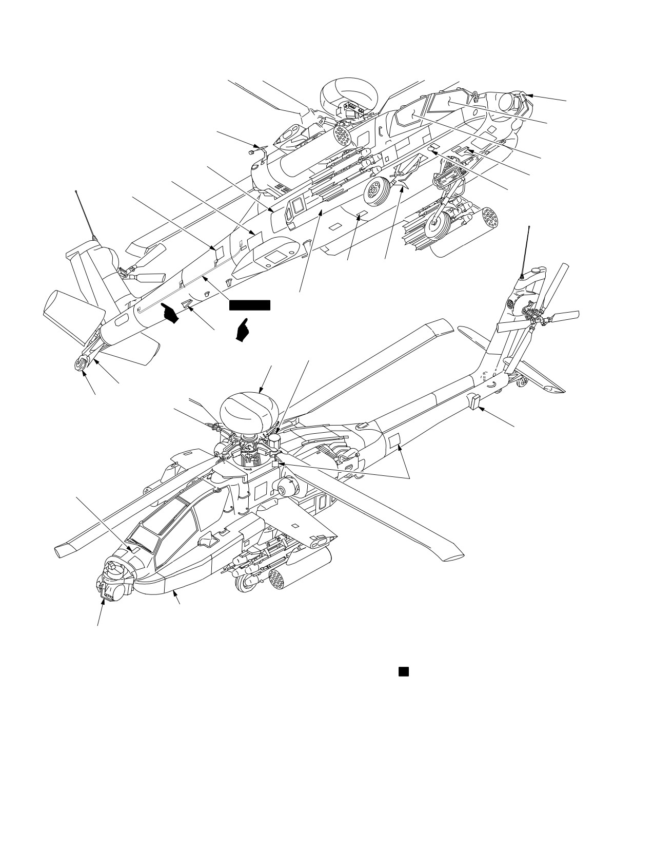
Sensor (PNVS) equipment.
WARNING
LASER LIGHT HAZARD
LASER LIGHT
The laser light beam is dangerous and can cause blindness if it enters the eye
either directly or reflected from a surface. Personnel should wear approved laser
protection whenever in a controlled area when laser rangefinder or laser target
designators are being used. Laser shall be used only in controlled areas by
qualified personnel.
Use or disclosure of this information is subject to the restriction(s) on the title page of this document.
b
TM 1-1520-251-10
WARNING
NOISE
Sound pressure levels around helicopters during some operating conditions
exceed the Surgeon General’s hearing conservation criteria as defined in DA
PAM 40 - 501 Hearing protection devices, such as the aviator helmet or ear plugs,
are required to be worn by all personnel in and around the helicopter during its
operation.
WARNING
STARTING ENGINES AND AUXILIARY POWER UNIT
Be sure that the rotor and blast area is clear, and a fire guard is posted if
available.
WARNING
VERTIGO
The anti - collision strobe lights should be off during flight through clouds to
prevent sensations of vertigo as a result of reflections of the light on the clouds.
WARNING
WEAPONS AND AMMUNITION
Observe all standard safety precautions governing the handling of weapons and
live ammunition. When not in use, point all weapons in a direction away from
personnel and property in case of accidental firing. Do not walk in front of
weapons. SAFE all weapons before servicing. To avoid potentially dangerous
situations, follow the procedural warnings in this text. To prevent inadvertent
rocket firing, electrical tests shall not be performed with rockets in launcher, and
all other sources of inadvertent electrical power shall be kept away from the
launcher. Ensure electrical equipment, even if turned off and unplugged, is not in
the vicinity of a loaded launcher.
WARNING
WING STORES JETTISON
All jettison safety pins shall be installed when the helicopter is on the ground.
Safety pins shall be removed prior to flight. Failure to do so will prevent jettison
of wing stores.
WARNING
RADIO FREQUENCY TRANSMISSION
Personnel should remain at least five feet away from the HF radio antenna while
the radio is transmitting. High levels of electromagnetic radiaton are emitted by
this antenna while transmitting. The HF radio should not be operated inside
hangar or metal covered building.
Use or disclosure of this information is subject to the restriction(s) on the title page of this document.
Change 2
c/(d blank)
TM 1-1520-251-10
C4
CHANGE
HEADQUARTERS
DEPARTMENT OF THE ARMY
}
NO.
4
WASHINGTON, D.C., 27 April 2005
TECHNICAL MANUAL
OPERATOR’S MANUAL
FOR
HELICOPTER, ATTACK,
AH-64D
LONGBOW APACHE
WARNING - This document contains technical data whose export is restricted by the Arms
Export Control Act (Title 22, U.S.C., Sec 2751, et seq.) or the Export Administration Act of 1979,
as amended, Title 50 U.S.C., App. 2401 et seq. Violation of these export laws are subject to
severe criminal penalties. Disseminate in accordance with provisions of DoD Directive 5230.25.
DISTRIBUTION STATEMENT D - Distribution authorized to the Department of Defense and
DoD contractors only due to critical technology. This determination was made on 26 June 2000.
Other requests for this document shall be referred to Commander, U.S. Army Aviation and
Missile Command, ATTN: SFAE - AV - AAH - ATH, Redstone Arsenal, AL 35898 - 5000.
DESTRUCTION NOTICE - Destroy by any method that will prevent disclosure of contents or
reconstruction of the document.
TM 1-1520-251-10, 29 March 2002, is changed as follows:
1. Remove old pages and insert new pages as indicated below. New or changed material is indicated by
vertical bar in the margin of the page. Revised illustrations are indicated by a miniature pointing hand.
Remove pages
Insert pages
A through C/(D blank)
A through D
1-1 and 1-2
1-1 and 1-2
2-3 and 2-4
2-3 and 2-4
2-13 and 2-14
2-13 and 2-14
2-25 and 2-26
2-25 and 2-26
2-41 and 2-42
2-41 and 2-42
2-49 and 2-50
2-49 and 2-50
2-57 through 2-60.1/(2-60.2 blank)
2-57 through 2-60.1/(2-60.2 blank)
2-101 through 2-106
2-101 through 2-106
2-127 and 2-128
2-127 and 2-128
2-128.1/(2-128.2 blank)
2-130.1/(2-130.2 blank)
2-135 and 2-136
2-135 and 2-136
2-139 and 2-140
2-139 and 2-140
2-143 and 2-144
2-143 and 2-144
2-146.1 and 2-146.2
2-146.1 and 2-146.2
2-147 and 2-148
(2 - 147 blank)/2 - 148
2-155 and 2-156
2-155 and 2-156
2-161 and 2-162
2-161 and 2-162
TM 1-1520-251-10
C4
Remove pages
Insert pages
3-41 and 3-42
3-41 and 3-42
3-66.13 and 3-66.14
3-66.13 and 3-66.14
3-66.39 and 3-66.40
3-66.39 and 3-66.40
3A - 3 and 3A - 4
3A - 3 and 3A - 4
3A - 9 through 3A - 14
3A - 9 through 3A - 14
3A - 17 through 3A - 28
3A - 17 through 3A - 26
3A - 26.1/(3A - 26.2 blank)
3A - 27 and 3A - 28
3A - 27 and 3A - 28
3A - 28.1 through 3A - 28.3/(3A - 28.4 blank)
3A - 35 through 3A - 38
3A - 35 through 3A - 38
3A - 47 through 3A - 58
3A - 47 through 3A - 58
3A - 63 through 3A - 72
3A - 63 through 3A - 72
3A - 100.5 through 3A - 100.18
3A - 100.5 through 3A - 100.18
(3A - 101 blank)/3A - 102
3A - 101 and 3A - 102
3A - 147 through 3A - 154
3A - 147 through 3A - 154
3A - 157 through 3A - 160
3A - 157 through 3A - 160
4-1 through 4-8
4-1 through 4-8
4-8.1/(4-8.2 blank)
4-11 through 4-16
4-11 through 4-16
4-16.1/(4-16.2 blank)
4-19 through 4-28
4-19 through 4-26
4-26.1 and 4-26.3/(4-26.4 blank)
4-27 and 4-28
4-33 through 4-36
4-33 through 4-36
4-36.1 and 4-36.2
4-65 and 4-68
4-65 and 4-68
4-72.1 and 4-72.2
4-72.1 and 4-72.2
4-73 and 4-74
4-73 and 4-74
4-78.1 through 4-78.5/(4-78.6 blank)
4-78.1 through 4-78.6
4-95 and 4-96
4-95 and 4-96
4-111 and 4-112
4-111 and 4-112
5-11 and 5-12
5-11 and 5-12
6-5 and 6-6
6-5 and 6-6
6-11 and 6-12
6-11 and 6-12
7-13 through 7-16
7-13 through 7-16
7A - 3 through 7A - 6
7A - 3 through 7A - 6
7A - 13 through 7A - 18
7A - 13 through 7A - 18
8-3 through 8-6
8-3 through 8-6
8-9 and 8-10
8-9 and 8-10
9-15 through 9-20
9-15 through 9-20
9-27 through 9-30
9-27 through 9-30
9-37 through 9-40
9-37 through 9-40
B-3 and B-4
B-3 and B-4
B-7 through B-12
B-7 through B-12
D-1 through D-4
D-1 through D-4
Index - 1 through index - 48
Index - 1 through index - 48
Index 49/(Index 50 blank)
Electronic 2028 Instruction Sheet and Blank
Electronic 2028 Instruction Sheet and Blank
2.
File this change sheet in the front of the publication for reference purposes.
TM 1-1520-251-10
C3
CHANGE
HEADQUARTERS
DEPARTMENT OF THE ARMY
}
NO.
3
WASHINGTON, D.C., 30 April 2004
TECHNICAL MANUAL
OPERATOR’S MANUAL
FOR
HELICOPTER, ATTACK,
AH-64D
LONGBOW APACHE
WARNING - This document contains technical data whose export is restricted by the Arms
Export Control Act (Title 22, U.S.C., Sec 2751, et seq.) or the Export Administration Act of 1979,
as amended, Title 50 U.S.C., App. 2401 et seq. Violation of these export laws are subject to
severe criminal penalties. Disseminate in accordance with provisions of DoD Directive 5230.25.
DISTRIBUTION STATEMENT D - Distribution authorized to the Department of Defense and
DoD contractors only due to critical technology. This determination was made on 26 June 2000.
Other requests for this document shall be referred to Commander, U.S. Army Aviation and
Missile Command, ATTN: SFAE - AV - AAH - ATH, Redstone Arsenal, AL 35898 - 5000.
DESTRUCTION NOTICE - Destroy by any method that will prevent disclosure of contents or
reconstruction of the document.
TM 1-1520-251-10, 29 March 2002, is changed as follows:
1. Remove old pages and insert new pages as indicated below. New or changed material is indicated by
vertical bar in the margin of the page. Revised illustrations are indicated by a miniature pointing hand.
Remove pages
Insert pages
A/(B blank)
A and B
C/(D blank)
i through iii/(iv blank)
i through iv
1-1 and 1-2
1-1 and 1-2
2-14.1 and 2-14.2
2-14.1 and 2-14.2
2-17 through 2-20
2-17 through 2-20
2-20.1 and 2-20.2
2-21 through 2-24
2-21 through 2-24
2-63 through 2-66
2-63 through 2-66
2-91 through 2-94
2-91 through 2-94
2-115 and 2-116
2-115 and 2-116
2-116.1 and 2-116.2
2-116.1 and 2-116.2
2-119 through 2-124
2-119 through 2-124
2-127 and 2-128
2-127 and 2-128
2-141 and 2-142
2-141 and 2-142
2-145 through 2-148
2-145 through 2-148
2-151 and 2-152
2-151 and 2-152
3-1 through 3-6
3-1 through 3-6
3-9 through 3-14
3-9 through 3-14
TM 1-1520-251-10
C 3
Remove pages
Insert pages
3-37 and 3-38
3-37 and 3-38
3-66.1 through 3-66.82
3-69 through 3-72
3-69 through 3-72
3-105 through 3-108
3-105 through 3-108
3A - 1 through 3A - 14
3A - 1 through 3A - 14
3A - 17 through 3A - 26
3A - 17 through 3A - 26
3A - 26.1/(3A - 26.2 blank)
3A - 27 and 3A - 28
3A - 27 and 3A - 28
3A - 31 through 3A - 36
3A - 31 through 3A - 36
3A - 43 and 3A - 44
3A - 43 and 3A - 44
3A - 47 and 3A - 48
3A - 47 and 3A - 48
3A - 53 through 3A - 56
3A - 53 through 3A - 56
3A - 63 and 3A - 64
3A - 63 and 3A - 64
3A - 73 and 3A - 74
3A - 73 and 3A - 74
3A - 81 through 3A - 102
3A - 81 through 3A - 100
3A - 100.1 through 3A - 100.18
3A - 101 and 3A - 102
(3A - 101 blank)/3A - 102
3A - 103 through 3A - 112
3A - 103 through 3A - 112
3A - 112.1/(3A - 112.2 blank)
3A - 115 through 3A - 122
3A - 115 through 3A - 122
3A - 122.1 through 3A - 122.4
3A - 125 and 3A - 126
3A - 125 and 3A - 126
3A - 129 through 3A - 132
3A - 129 through 3A - 132
3A - 132.1 through 3A - 132.4
3A - 135 and 3A - 136
3A - 135 and 3A - 136
3A - 141 through 3A - 156
3A - 141 through 3A - 156
4-5 and 4-6
4-5 and 4-6
4-9 through 4-12
4-9 through 4-12
4-15 through 4-26
4-15 through 4-26
4-26.1 and 4-26.2
4-27 and 4-28
4-27 and 4-28
4-33 through 4-36
4-33 through 4-36
4-41 and 4-42
4-41 and 4-42
4-45 through 4-52
4-45 through 4-52
4-55 through 4-58
4-55 through 4-58
4-61 through 4-64
4-61 through 4-64
4-69 through 4-72
4-69 through 4-72
4-72.1 and 4-72.2
4-72.1 through 4-72.4
4-73 through 4-78
4-73 through 4-78
4-78.1 through 4-78.5/(4-78.6 blank)
4-81 through 4-84
4-81 through 4-84
4-107 and 4-108
4-107 and 4-108
4-113 and 4-114
4-113 and 4-114
4-117 and 4-118
4-117 and 4-118
5-11 and 5-12
5-11 and 5-12
7-1 through 7-4
7-1 through 7-4
7A - 1 through 7A - 4
7A - 1 through 7A - 4
7A - 53 and 7A - 54
7A - 53 and 7A - 54
8-3 through 8-6
8-3 through 8-6
TM 1-1520-251-10
C3
Remove pages
Insert pages
9-5 and 9-6
9-5 and 9-6
9-17 through 9-22
9-17 through 9-22
9-27 through 9-30
9-27 through 9-30
B-1 and B-2
B-1 and B-2
B-7 and B-8
B-7 and B-8
B-11 and B-12
B-11 and B-12
C-5/(C-6 blank)
Index 1 through Index 41/(Index 42 blank)
Index 1 through Index 48
Cover Page
Cover Page
2. File this change sheet in the front of the publication for reference purposes.
By Order of the Secretary of the Army:
PETER J. SCHOOMAKER
General, United States Army
Official:
Chief of Staff
JOEL B. HUDSON
Administrative Assistant to the
Secretary of the Army
0409004
DISTRIBUTION:
To be distributed in accordance with the the Initial Distribution Number (IDN) 313360,
requirements for TM 1-1520-251-10.
TM 1-1520-251-10
C 2
CHANGE
HEADQUARTERS
DEPARTMENT OF THE ARMY
}
NO.
2
WASHINGTON, D.C., 1 August 2003
TECHNICAL MANUAL
OPERATOR’S MANUAL
FOR
HELICOPTER, ATTACK,
AH-64D
LONGBOW APACHE
DISTRIBUTION STATEMENT C: Distribution authorized to U.S. Government agencies and their contractors only
to protect technical or operational information from automatic dissemination under the International Exchange
Program or by other means. This determination was made on 1 July 1994. Other requests for this document will be
referred to U.S. Army Aviation and Missile Command, ATTN: AMSAM - MMC - MA - NP, Redstone Arsenal, AL.,
35895 - 5230.
TM 1-1520-251-10, 29 March 2002, is changed as follows:
1. Remove old pages and insert new pages as indicated below. New or changed material is indicated by
vertical bar in the margin of the page. Revised illustrations are indicated by a miniature pointing hand.
Remove pages
Insert pages
a and b
a and b
c/(d blank)
c/(d blank)
A/(B blank)
A and B
i and ii
i and ii
1-1 and 1-2
1-1 and 1-2
2-1 through 2-10
2-1 through 2-10
-
-
-
-
-
2-10.1 and 2-10.2
2-11 through 2-14
2-11 through 2-14
-
-
-
-
-
2-14.1 and 2-14.2
2-17 through 2-30
2-17 through 2-30
2-35 through 2-38
2-35 through 2-38
2-43 through 2-46
2-43 through 2-46
2-49 and 2-50
2-49 and 2-50
2-50.1 and 2-50.2
2-50.1 and 2-50.2
2-57 through 2-60
2-57 through 2-60
-
-
-
-
-
2-60.1/(2-60.2 blank)
2-61 and 2-62
2-61 and 2-62
2-65 and 2-66
2-65 and 2-66
2-69 and 2-70
2-69 and 2-70
2-73 and 2-74
2-73 and 2-74
2-79 and 2-80
2-79 and 2-80
2-83 through 2-96
2-83 and 2-84
2-84.1 through 2-84.5/(2-84.6 blank)
2-85 through 2-96
2-103 and 2-104
2-103 and 2-104
(2 - 111 blank)/2 - 112
(2 - 111 blank)/2 - 112
TM 1-1520-251-10
C 2
Remove pages
Insert pages
2-115 through 2-164
2-115 and 2-116
-
-
-
-
-
2-116.1 and 2-116.2
-
-
-
-
-
2-117 through 2-140
-
-
-
-
-
2-140.1 and 2-140.2
2-141 through 2-164
3-1 and 3-2
3-1 and 3-2
3-11 through 3-14
3-11 through 3-14
3-41 and 3-42
3-41 and 3-42
3-69 through 3-72
3-69 through 3-72
3-77 and 3-78
3-77 and 3-78
3-87 through 3-90
3-87 through 3-90
-
-
-
-
-
3A - 1 through 3A - 160
4-25 and 4-26
4-25 and 4-26
4-61 through 4-72
4-61 through 4-72
-
-
-
-
-
4-72.1 and 4.72.2
4-73 and 4-74
4-73 and 4-74
4-77 and 4-78
4-77 and 4-78
4-93 through 4-98
4-93 through 4-98
4-105 through 4-108
4-105 through 4-108
4-113 through 4-118
4-113 through 4-118
5-11 and 5-12
5-11 and 5-12
6-5 and 6-6
6-5 and 6-6
6-10.1 /( 6-10.2 .blank)
6-10.1 and 6-10.2
7-13 and 7-14
7-13 and 7-14
7A - 3 and 7A - 4
7A - 3 and 7A - 4
7A - 13 and 7A - 14
7A - 13 and 7A - 14
8-1 and 8-2
8-1 and 8-2
8-5 through 8-20
8-5 through 8-20
8-21/(8-22 blank)
8-21/(8-22 blank)
9-1 through 9-34
9-1 through 9-42
A-1 and A-2
A-1 and A-2
B-1 through B13/(B14 blank)
B-1 through B14
Index 1 through Index 32
Index1 through Index 41/(Index 42 blank)
DA - Form 2028 - 2, 1 Jul 79
DA - Form 2028, Feb 74
2.
File this change sheet in the front of the publication for reference purposes.
TM 1-1520-251-10
C 2
By Order of the Secretary of the Army:
PETER J. SCHOOMAKER
General, United States Army
Official:
Chief of Staff
JOEL B. HUDSON
Administrative Assistant to the
Secretary of the Army
0319202
DISTRIBUTION:
To be distributed in accordance with the the Initial Distribution Number (IDN) 313360,
requirements for TM 1-1520-251-10.
TM 1-1520-251-10
C 1
CHANGE
HEADQUARTERS
DEPARTMENT OF THE ARMY
}
NO.
1
WASHINGTON, D.C., 23 August 2002
TECHNICAL MANUAL
OPERATOR’S MANUAL
FOR
HELICOPTER, ATTACK,
AH-64D
LONGBOW APACHE
DISTRIBUTION STATEMENT C: Distribution authorized to U.S. Government agencies and their contractors only
to protect technical or operational information from automatic dissemination under the International Exchange
Program or by other means. This determination was made on 1 July 1994. Other requests for this document will be
referred to U.S. Army Aviation and Missile Command, ATTN: AMSAM - MMC - MA - NP, Redstone Arsenal, AL.,
35895 - 5230.
TM 1-1520-251-10, 29 March 2002, is changed as follows:
1. Remove old pages and insert new pages as indicated below. New or changed material is indicated by
vertical bar in the margin of the page. Revised illustrations are indicated by a miniature pointing hand.
Remove pages
Insert pages
A/(B blank)
A/(B blank)
2-43 through 2-50
2-43 through 2-50
-
-
-
-
2-50.1 and 2-50.2
2-107 through 2-110
2-107 through 2-110
-
-
-
-
2-110.1 and 2-110.2
2-111 and 2-112
(2 - 111 blank)/2 - 112
2-115 through 2-118
2-115 through 2-118
4-93 and 4-94
4-93 and 4-94
-
-
-
-
6-10.1/(6-10.2 blank)
Index 3 through Index 6
Index 3 through Index 6
Index 11 through Index 20
Index 11 through Index 20
Index 23 and Index 24
Index 23 and Index 24
Index 27 through 30
Index 27 through 30
2. File this change sheet in the front of the publication for reference purposes.
TM 1-1520-251-10
C 1
By Order of the Secretary of the Army:
ERIC K. SHINSEKI
General, United States Army
Official:
Chief of Staff
JOEL B. HUDSON
Administrative Assistant to the
Secretary of the Army
0224708
DISTRIBUTION:
To be distributed in accordance with the the Initial Distribution Number (IDN) 313360,
requirements for TM 1-1520-251-10.
TM 1-1520-251-10
INSERT LATEST CHANGED PAGES: DESTROY SUPERSEDED PAGES.
NOTE: The portion of the text affected by the changes is indicated by a
LIST OF EFFECTIVE PAGES
vertical line in the outer margins of the page. Changes to
illustrations are indicated by miniature pointing hands. Changes
to wiring diagrams are indicated by shaded areas.
Date of issue for original and change pages are:
Original
0
29 March 2002
Change
3
30 April 2004
Change
1
23 August 2002
Change
4
27 Apri l 2005
Change
2
01 August 2003
Change
5
. . . . . . . . .26 July
2005
TOTAL NUMBER OF PAGES IN THIS PUBLICATION IS 1057 CONSISTING OF THE FOLLOWING:
Page
*Change
Page
*Change
No.
No.
No.
No.
Cover
3
2-58 -- 2-60
4
Blank
0
2-60.1
4
a
2
2-60.2 Blank Added
2
b
0
2-61 -- 2-62
2
c
2
2-63
0
d Blank
0
2-64
3
A -- D
5
2-65
3
i -- iv
3
2-66 -- 2-69
0
1-1
0
2-70
2
1-2
4
2-71 -- 2-72
1
2-1
0
2-73
2
2-2
2
2-74 -- 2-79
0
2-3
4
2-80
2
2-4 -- 2-5
0
2-81 -- 2-83
0
2-6 -- 2-10
2
2-84
2
2-10.1 -- 2-10.2
2
2-84.1 -- 2-84.5 Added
2
2-11 -- 2-12
2
2-84.6 Blank Added
2
2-13
4
2-85 -- 2-89
2
2-14
2
2-90
0
2-14.1
3
2-91
3
2-14.2
2
2-92
0
2-15 -- 2-17
0
2-93
3
2-18 -- 2-20
3
2-94 -- 2-95
2
2-20.1 -- 2-20.2 Added
3
2-96 -- 2-100
0
2-21
3
2-101
4
2-22
2
2-102
0
2-23
0
2-103 -- 2-105
4
2-24
3
2-106
0
2-25
4
2-107 -- 2-110
1
2-26 -- 2-30
2
2-110.1 -- 2-110.2 Added
1
2-31 -- 2-35
0
2-111 Blank
2
2-36 -- 2-37
2
2-112
1
2-38
2
2-113 -- 2-114
0
2-39 -- 2-41
0
2-115
1
2-42
4
2-116
3
2-43
2
2-116.1 -- 2-116.2
3
2-44
1
2-117
2
2-45 -- 2-46
2
2-118
0
2-47 -- 2-48
1
2-119 -- 2-120
3
2-49
4
2-121
2
2-50
2
2-122
3
2-50.1 -- 2-50.2
2
2-123
2
2-51 -- 2-56
0
2-124
3
2-57
2
2-125 -- 2-126
2
*Zero in this column indicates an original page.
Use or disclosure of this information is subject to the restriction(s) on the title page of this document.
Change
5
A
TM 1-1520-251-10
INSERT LATEST CHANGED PAGES: DESTROY SUPERSEDED PAGES.
LIST OF EFFECTIVE PAGES
Page
*Change
Page
*Change
No.
No.
No.
No.
2-127 -- 2--128
4
3A-5
2
2-128.1/(2--128.2 blank) Added
4
3A-6 -- 3A-9
3
2-130.1/(2--130.2 blank) Added
4
3A-10 -- 3A-11
4
2-129 -- 2-135
2
3A-12 -- 3A-13
2
2-136
4
3A-14
4
2-137 -- 2-138
2
3A-15 -- 3A-16
2
2-139
4
3A-17 -- 3A-26
4
2-140
2
3A-26.1
4
2-140.1 -- 2-140.2
2
3A-26.2 Blank
4
2-141
3
3A-27 -- 3A-28
4
2-142 -- 2-143
2
3A-28.1 -- 3A-28.3 Added
4
2-144
4
3A-28.4 Blank Added
4
2-145
2
3A-29 -- 3A-30
2
2-146
3
3A-31 -- 3A-32
3
2-146.1 -- 2-146.2 Added
4
3A-33
2
2-147 Blank Added
4
3A-34
3
2-148
4
3A-35
2
2-149 -- 2-150
2
3A-36-- 3A-38
4
2-151 -- 2-152
3
3A-39 -- 3A-42
2
2-153 -- 2-154
2
3A-43
3
2-155 -- 2-156
4
3A-44 -- 3A-46
2
2-157 -- 2-160
2
3A-47 -- 3A-58
4
2-161
4
3A-59 -- 3A-63
2
2-162 -- 2-164
2
3A-64 --3A-67
4
3-1 -- 3-6
3
3A-68 -- 3A-69
2
3-7 -- 3-9
0
3A-70 -- 3A-72
4
3-10 -- 3-13
3
3A-73
3
3-14
2
3A-74 -- 3A-80
2
3-15 -- 3-37
0
3A-81 -- 3A-100
3
3-38
3
3A-100.1 -- 3A-100.5 Added
3
3-39 -- 3-40
0
3A-100.6 -- 3A-100.18
4
3-41
4
3A-101
4
3-42 -- 3-66
0
3A-102
4
3-66.1 -- 3-66.12 Added
3
3A-103
2
3-66.13
4
3A-104 -- 3A-105
3
3-66.14 -- 3-66.38
3
3A-106
2
3-66.39
4
3A-107 -- 3A-112
3
3-66.40 -- 3-66.82
3
3A-112.1
3
3-67 -- 3-68
0
3A-112.2 Blank Added
3
3-69
2
3A-113 -- 3A-115
2
3-70 -- 3-71
3
3A-116
3
3-72 -- 3-77
0
3A-117
2
3-78
2
3A-118 -- 3A-122
3
3-79 -- 3-86
0
3A-122.1 -- 3A-122.4 Added
3
3-87
2
3A-123 -- 3A-125
2
3-88
0
3A-126
3
3-89
2
3A-127
2
3-90 -- 3-105
0
3A-128
0
3-106 -- 3-107
3
3A-129 -- 3A-132
3
3-108
0
3A-132.1 -- 3A-132.4 Added
3
3A-1 -- 3A-2
3
3A-133 -- 3A-134
2
3A-3 -- 3A-4
4
3A-135
3
*Zero in this column indicates an original page.
Use or disclosure of this information is subject to the restriction(s) on the title page of this document.
B
Change 4
TM 1-1520-251-10
INSERT LATEST CHANGED PAGES: DESTROY SUPERSEDED PAGES.
LIST OF EFFECTIVE PAGES
Page
*Change
Page
*Change
No.
No.
No.
No.
3A-136 -- 3A-140
2
4-72.3 -- 4-72.4 Added
3
3A-141
3
4-73
3
3A-142
2
4-74
4
3A-143 -- 3A-146
3
4-75 -- 4-78
3
3A-147
2
4-78.1 Added
3
3A-148 -- 3A-153
4
4-78.2 -- 4-78.6
4
3A-154 -- 3A-156
3
4-79 -- 4-81
0
3A-157
2
4-82 -- 4-83
3
3A-158 -- 3A-160
4
4-84 -- 4-92
0
4-1
4
4-93
2
4-2
0
4-94 -- 4-95
0
4-3
4
4-96
4
4-4
U
4-97
2
4-5 -- 4-8
4
4-98 -- 4-105
0
4-8.1/(4.8.2 Blank) Added
4
4-106 -- 4-107
2
4-9
3
4-108 -- 4-111
0
4-10
0
4-112
4
4-11 -- 4-16
4
4-113
0
4-16.1/(4.16.2 Blank) Added
4
4-114
3
4-17
0
4-115 -- 4-117
2
4-18
3
4-118
3
4-19 -- 4-24
4
5-1 -- 5-11
0
4-25
3
5-12
4
4-26
4
5-13
0
4-26.1 -- 4-26.2
4
5-14 Blank
0
4-26.3/(4-26.4 blank)
4
6-1 -- 6-5
0
4-27
0
6-6
4
4-28
4
6-7 -- 6-10
0
4-29 -- 4-32
0
6-10.1 -- 6-10.2
2
4-33 -- 4-36
4
6-11
0
4-36.1 -- 4-36.2 Added
4
6-12
4
4-37 -- 4-40
0
6-13 -- 6-19
0
4-41
3
6-20 Blank
0
4-42 -- 4-44
0
7-1-- 7-4
3
4-45
3
7-5 -- 7-12
0
4-46
0
7-13
4
4-47 -- 4-48
3
7-14
0
4-49
0
7-15
4
4-50 -- 4-51
3
7-16 -- 7-74
0
4-52 -- 4-54
0
7A-1 -- 7A-3
3
4-55
3
7A-4 -- 7A-5
4
4-56 -- 4-57
0
7A-6 -- 7A-13
0
4-58
3
7A-14 -- 7A-16
4
4-59 -- 4-60
0
7A-17
0
4-61 -- 4-62
3
7A-18
4
4-63
2
7A-19 -- 7A-53
0
4-64
3
7A-54
3
4-65 -- 4-67
4
7A-55 -- 7A-76
0
4-68
2
8-1
0
4-69 -- 4-72
3
8-2
2
4-72.1
4
8-3
0
4-72.2
3
8-4 -- 8-5
4
*Zero in this column indicates an original page.
Use or disclosure of this information is subject to the restriction(s) on the title page of this document.
Change
4
C
TM 1-1520-251-10
INSERT LATEST CHANGED PAGES: DESTROY SUPERSEDED PAGES.
LIST OF EFFECTIVE PAGES
Page
*Change
Page
*Change
No.
No.
No.
No.
8-6
3
B-3
2
8-7 -- 8-8
2
B-4
4
8-9
4
B5 -- B-7
2
8-10 -- 8-11
2
B-8 -- B-9
4
8-12 -- 8-13
0
B-10
2
8-14 -- 8-21
2
B-11
4
8-22 Blank
0
B-12 -- B-14
2
9-1 -- 9-5
2
C-1 -- C-4
0
9-6
3
C-5 Added
3
9-7 -- 9-14
2
C-6 Blank Added
3
9-15 -- 9-16
4
D-1
4
9-17
2
D-2
0
9-18
4
D-3 -- D-4
4
9-19
5
Index-1 -- Index-48
4
9-20
5
Index-49/)Index 50 blank) Added
4
9-21 -- 9-22
3
Blank
0
9-23 -- 9-27
2
Electronic 2028 Instructions
4
9-28 -- 9-30
4
9-31 -- 9-37
2
Blank
0
9-38 -- 9-40
4
2028 - Example
2
9-41 -- 9-42
2
2028 - Example
2
A-1
2
2028
2
A-2
0
2028
2
B-1
2
Metric Conversion
0
B-2
3
Back Cover
0
*Zero in this column indicates an original page.
Use or disclosure of this information is subject to the restriction(s) on the title page of this document.
D
Change 5
*TM 1-1520-251-10
Technical Manual
HEADQUARTERS
DEPARTMENT OF THE ARMY
No. 1-1520-251-10
WASHINGTON, D. C., 29 March 2002
TECHNICAL MANUAL
OPERATOR’S MANUAL
FOR
HELICOPTER, ATTACK
AH-64D LONGBOW/APACHE
REPORTING ERRORS AND RECOMMENDING IMPROVEMENTS
You can help improve this publication. If you find any mistakes, or if you know of a way to improve these
procedures, please let us know. Mail your letter or DA Form 2028 (Recommended Changes to
Publications and Blank Forms) directly to: Commander, US Army Aviation and Missile Command, ATTN:
AMSAM - MMC - MA - NP Redstone Arsenal, AL, 35898 - 5230. You may also submit your recommended
changes by E - mail directly to 2028@redstone.army.mil or by fax (256) 842 - 6546 or DSN 788 - 6546. A
reply will be furnished directly to you. Instructions for sending an electronic 2028 may be found at the
back of this publication. For the World Wide Web use: https://amcom2028.redstone.army.mil.
WARNING - This document contains technical data whose export is restricted by the Arms
Export Control Act (Title 22, U.S.C., Sec 2751, et seq.) or the Export Administration Act of 1979,
as amended, Title 50 U.S.C., App. 2401 et seq. Violation of these export laws are subject to
severe criminal penalties. Disseminate in accordance with provisions of DoD Directive 5230.25.
DISTRIBUTION STATEMENT D - Distribution authorized to the Department of Defense and
DoD contractors only due to critical technology. This determination was made on 26 June 2000.
Other requests for this document shall be referred to Commander, U.S. Army Aviation and
Missile Command, ATTN: SFAE - AV - AAH - ATH, Redstone Arsenal, AL 35898 - 5000.
DESTRUCTION NOTICE - Destroy by any method that will prevent disclosure of contents or
reconstruction of the document.
TABLE OF CONTENTS
Page
CHAPTER 1
INTRODUCTION .
1-1
CHAPTER 2
AIRCRAFT AND SYSTEMS DESCRIPTION AND OPERATION .
2-1
Section I.
Aircraft .
2-1
Section II.
Emergency Equipment .
2-27
Section III.
Engines and Related Systems .
2-31
Section IV.
Fuel Supply System .
2-43
Section V.
Flight Control System .
2-51
Section VI.
Hydraulic and Integrated Pressurized Air Systems (IPAS) .
2-62
Section VII.
Drive Train System .
2-71
Section VIII.
Rotors .
2-74
* This manual supersedes TM 1-1520-251-10, dated 15 December 1998, including all changes.
Use or disclosure of this information is subject to the restriction(s) on the title page of this document.
Change 3
i
TM 1-1520-251-10
TABLE OF CONTENTS - continued
Page
Section IX.
Utility Systems .
2-76
Section X.
Environmental Control System .
2-78
Section XI.
Electrical System .
2-81
Section XII.
Auxiliary Power Unit (APU) .
2-94
Section XIII.
Lighting .
2-96
Section XIV.
Flight Instruments .
2-100
Section XV.
Servicing, Parking, and Mooring .
2-107
Section XVI.
Data Management System .
2-120
Section XVII.
Warnings/Cautions/Advisory Messages .
2-141
CHAPTER 3
BLK 1
AVIONICS .
3-1
Section I.
General .
3-1
Section II.
Communications Subsystem .
3-6
Section IIA.
HF
Communications Subsystem .
3-66.1
Section III.
Navigation Subsystem .
3-67
CHAPTER 3A
BLK 2
AVIONICS .
3A-1
Section I.
General .
3A-1
Section II.
Communications Subsystem .
3A-6
Section III.
Navigation Subsystem .
3A-99
CHAPTER 4
MISSION EQUIPMENT .
4-1
Section I.
Sighting Subsystem .
4-1
Section II.
Armament Systems .
4-79
Section III.
Active and Passive Defense Equipment .
4-108
CHAPTER 5
OPERATING LIMITS AND RESTRICTIONS .
5-1
Section I.
General .
5-1
Section II.
System Limits .
5-2
Section III.
Power Limits .
5-4
Section IV.
Loading Limits .
5-9
Section V.
Airspeed Limits .
5-9
Section VI.
Manuevering Limits .
5-12
Section VII.
Environmental Restrictions .
5-12
Section VIII.
Other Limits .
5-12
Use or disclosure of this information is subject to the restriction(s) on the title page of this document.
ii
Change 3
TM 1-1520-251-10
TABLE OF CONTENTS - continued
Page
CHAPTER 6
WEIGHT/BALANCE AND LOADING .
6-1
Section
I.
Genral .
6-1
Section
II.
Weight and Balance .
6-3
Section
III.
Fuel and Oil .
6-6
Section
IV.
Personnel .
6-11
Section
V.
Mission Equipment .
6-12
Section
VI.
Cargo Loading .
6-16
Section
VII.
Allowable Loading .
6-18
CHAPTER 7
PERFORMANCE DATA FOR AH-64D HELICOPTERS
EQUIPPED WITH T700-GE-701 ENGINES .
7-1
Section
I.
Introduction .
7-1
Section
II.
Maximum Torque Available .
7-10
Section
III.
Hover Ceiling .
7-15
Section
IV.
Hover .
7-17
Section
V.
Cruise
7-19
Section
VI.
Drag .
7-70
Section
VII.
Climb Descent .
7-73
CHAPTER 7A
PERFORMANCE DATA FOR AH-64D HELICOPTERS
EQUIPPED WITH T700-GE-701C ENGINES .
7A-1
Section
I.
Introduction .
7A-1
Section
II.
Maximum Torque Available .
7A-10
Section
III.
Hovering Ceiling .
7A-16
Section
IV.
Hover .
7A-19
Section
V.
Cruise
7A-21
Section
VI.
Drag .
7A-72
Section
VII.
Climb - Descent
7A-75
CHAPTER 8
NORMAL PROCEDURES .
8-1
Section
I.
Crew Duties/Responsibilities .
8-1
Section
II.
Operating Procedures and Maneuvers .
8-2
Section
III.
Instrument Flight .
8-18
Section
IV.
Flight Characteristics .
8-18
Section
V.
Adverse Environmental Conditions .
8-18
CHAPTER 9
EMERGENCY PROCEDURES .
9-1
Section
I.
Helicopter Systems .
9-1
Section
II.
Mission Equipment .
9-21
Section
III.
Warning/Caution/Advisory Messages .
9-24
Use or disclosure of this information is subject to the restriction(s) on the title page of this document.
Change 3
iii
TM 1-1520-251-10
TABLE OF CONTENTS - continued
Page
APPENDIX A
REFERENCES .
A-1
APPENDIX B
ABBREVIATIONS AND TERMS .
B-1
APPENDIX C
TWO LETTER IDENTIFIERS AND SYMBOLS .
C-1
APPENDIX D
RADAR FREQUENCY INTERFEROMETER (RFI) DETECTED
AND FIRE CONTROL RADAR (FCR) MERGED SYMBOLs .
D-1
ALPHABETICAL INDEX .
Index 1
Use or disclosure of this information is subject to the restriction(s) on the title page of this document.
iv
Change 3
TM 1-1520-251-10
CHAPTER 1
INTRODUCTION
1.1 GENERAL
THIS MANUAL SHALL BE CARRIED IN THE
HELICOPTER AT ALL TIMES.
These instructions are for use by the operators. They ap-
ply to the AH-64D Apache helicopter.
1.4 APPENDIX A, REFERENCES
1.2 WARNINGS, CAUTIONS, AND NOTES DEFINED
Appendix A is a listing of official publications cited within
this manual which are applicable to, and available for,
Warnings, Cautions, and Notes are used to emphasize
flight crews.
important and critical instruction and are used for the fol-
lowing conditions:
1.5 APPENDIX B, ABBREVIATIONS AND TERMS
WARNING
Appendix B is a list of abbreviations to be used to clarify
the text in this manual only. They are not necessarily stan-
dard abbreviations.
An operating procedure, practice, condi-
tion or statement, which if not correctly
followed, could result in personal injury
1.6 APPENDIX C, TWO LETTER IDENTIFIERS AND
or loss of life.
SYMBOLS
Appendix C is a listing of two letter identifiers and symbols
CAUTION
used within this manual which are applicable to, and avail-
able for, flight crews.
An operating procedure, practice, condition
or statement, which if not strictly observed,
1.7 APPENDIX D, TACTICAL SITUATION DISPLAY
could result in damage to or destruction of,
(TSD) PREPLANNED, RADAR FREQUENCY
equipment, loss of mission effectiveness or
INTERFEROMETER (RFI) DETECTED, AND FIRE
long term health hazards to personnel.
CONTROL RADAR (FCR) MERGED SYMBOLS
NOTE
Appendix D is a listing of TSD, RFI and FCR symbols
An operating procedure, condition or state-
used within this manual which are applicable to, and avail-
ment, which is essential to highlight.
able for, flight crews.
1.8 INDEX
1.3 DESCRIPTION
The Index lists, in alphabetical order, every titled para-
This manual contains the best operating instructions and
graph, figure, and table contained in this manual. Chapter
procedures for the AH-64D Apache helicopter under most
7 and 7A Performance Data, have an additional index.
circumstances. The helicopter is capable of carrying two
crewmembers; a pilot and a Copilot/Gunner (CPG). The
helicopter is designed as a weapons delivery platform and
1.9 ARMY AVIATION SAFETY PROGRAM
is equipped with: a M230E1, 30mm automatic gun, aerial
rockets system (2.75 inch folding fin), and point target
Reports necessary to comply with the safety program are
weapons (Hellfire missiles). The observance of limita-
prescribed in AR 385-40.
tions, performance, and weight and balance data pro-
vided in this manual is mandatory. The observance of pro-
1.10 DESTRUCTION OF ARMY MATERIEL TO
cedures is also mandatory, except when modification is
PREVENT ENEMY USE
required because of multiple emergencies, adverse
weather, terrain, etc. Basic flight principles are not in-
For information concerning destruction of Army materiel
cluded.
to prevent enemy use refer to TM 750-244-1-5.
Use or disclosure of this information is subject to the restriction(s) on the title page of this document.
1-1
TM 1-1520-251-10
1.11 FORMS AND RECORDS
installed for MTADS and Modernized PNVS (MPNVS).
The text will state “if the aircraft is equipped with MTADS -
Army aviator’s flight record and aircraft maintenance re-
MPNVS provisions - - ”.
cords, which are to be used by crewmembers, are de-
scribed in DA PAM 738-751 and TM 55-1500-342-23.
Block 1
Block 1 aircraft are equipped with Lot 6 software which
1.12 EXPLANATION OF CHANGE SYMBOLS
provides unique functionality. Block 1 aircraft will use
chapters 1, 2, 3, 4, 5, 6, 7
, 7A
, (depending on
Changes to the text and tables, including new material on
which engine is installed), 8 and 9 of this manual. Equip-
added pages, are indicated by a vertical bar in the outer
ment/Systems that are only applicable to Block 1 will have
margin extending close to the entire area of the material
the data prefaced with a
BLK 1
icon. If the data is only
affected. Pages with emergency markings, which consist
applicable to a specific block, that data will start and end
of black diagonal lines around three edges, shall have the
with a bracket ( [ ] ) i.e. [
BLK 1
Only applicable to Block
vertical change bar placed along the outer margins be-
1 aircraft.] Units operating Block 1 aircraft may store the
tween the text and diagonal lines. Change bars show cur-
added chapter 3A at the direction of the commander.
rent changes only. A miniature pointing hand (symbol) is
used to denote a changed illustration. A vertical line in the
Block 1 aircraft with ARC - 220 HF Radio
outer margin, rather than miniature pointing hands, is uti-
Block 1 aircraft equipped with ARC - 220 HF Radio will
lized when there have been extensive changes made to
have data prefaced with
HF
. Chapter 3 Section IIA is
an illustration. Change symbols are not used to indicate:
a stand alone section for aircraft with the HF radio.
• Introductory material.
Block 2
• Indexes and tabular data where the change
The major differences between Block 1 and Block 2 air-
cannot be identified.
craft are unique software, ARC - 220 HF Radio, Enhanced
UFD, Expanded Data Transfer Unit, Digital Map, TEAC
• Blank space resulting from the deletion of text, an
V80AB Video Recorder, IDM - EPLRS, Emergency Loca-
illustration, or a table.
tor Transmitter and Underwater Acoustic Beacon. Block 2
• Correction of minor inaccuracies, such as spelling,
aircraft will use chapters 1, 2, 3A, 4, 5, 6, 7
, 7A
,
punctuation, relocation of material etc., unless
(depending on which engine is installed), 8 and 9 of this
such correction changes the meaning of instruc-
manual. Equipment/Systems that are only applicable to
tive information and procedures.
Block 2 will have the data prefaced with a
BLK 2
icon.
Block 2 illustrations will be shown with the text explaining
1.13 SERIES AND EFFECTIVITY CODES
the differences between Block 1 and Block 2 aircraft. If the
differences are extensive, both Block 1 and block 2 il-
Some AH-64D helicopters have Longbow mission equip-
lustrations will be shown. If the data is only applicable to a
ment installed. Those helicopters will have components,
specific block, that data will start and end with a bracket
displays, and procedures different from non Longbow air-
( [ ] ) i.e. [
BLK 2
Only applicable to to Block 2 aircraft.]
craft. The designator symbol
indicates text headings,
Units operating Block 2 aircraft may store the added chap-
text contents, and illustrations pertaining to helicopters
ter 3 at the direction of the commander.
with Longbow mission equipment installed. (See Chapter
4 for listing of Longbow Fire Control Radar.)
1.14 ILLUSTRATIONS
Some AH-64D helicopters have T700-GE-701 engines
The exterior aircraft illustrations in this manual will depict
installed. Those helicopters will have components, instru-
the Mast Mounted Assembly (MMA) installed unless the
mentation, and procedures different from helicopters with
illustration is specifically required technically to omit the
T700-GE-701C engines installed. The designator sym-
MMA.
bols
and
indicate material that pertains to those
specific engines.
1.15 USE OF SHALL, SHOULD, AND MAY
Some AH64D helicopters have Modernized TADS
Within this technical manual, the word shall is used to in-
(MTADS) software and hardware installed. The designa-
dicate a mandatory requirement. The word should is
tor symbol
MT
indicates text that pertains to helicopters
used to indicate a non-mandatory but preferred method of
with MTADS software and hardware installed. Some
accomplishment. The word may is used to indicate an ac-
AH64D helicopters have software (without hardware)
ceptable method of accomplishment.
Use or disclosure of this information is subject to the restriction(s) on the title page of this document.
1-2
Change 4
TM 1-1520-251-10
CHAPTER 2
AIRCRAFT AND SYSTEMS DESCRIPTION AND OPERATION
Section I.
AIRCRAFT
2.1 GENERAL
bay and stowage compartments are contained in the aft
section. The tail rotor, drive shafts, gearboxes, and stabi-
The AH-64D Apache helicopter is a twin engine, tandem
lator are attached to the aft section.
seat, aerial weapons platform.
2.5 ROTOR
2.2 INTRODUCTION
The helicopter has a fully articulated four-blade main rotor
system equipped with elastomeric lead-lag dampers. The
This chapter describes the crew interface requirements
tail rotor is a semi rigid design and consists of four blades.
for management of AH-64D Apache aircraft systems. Air-
craft systems are the non-avionics systems that provide
2.6 ENGINES
basic aircraft operations. Interface with aircraft systems is
provided by the multiplex (MUX) data bus, serial link, and
The helicopter is powered by two horizontally mounted
status lines. The aircraft MUX bus system provides the
turboshaft engines. Power is supplied to the main trans-
main interface for units involved in aircraft systems man-
mission through engine mounted nose gearboxes, shafts,
agement.
and over-running clutches. The main transmission drives
the main and tail rotors and accessory gearbox.
2.3 GENERAL ARRANGEMENT
2.7 WINGS
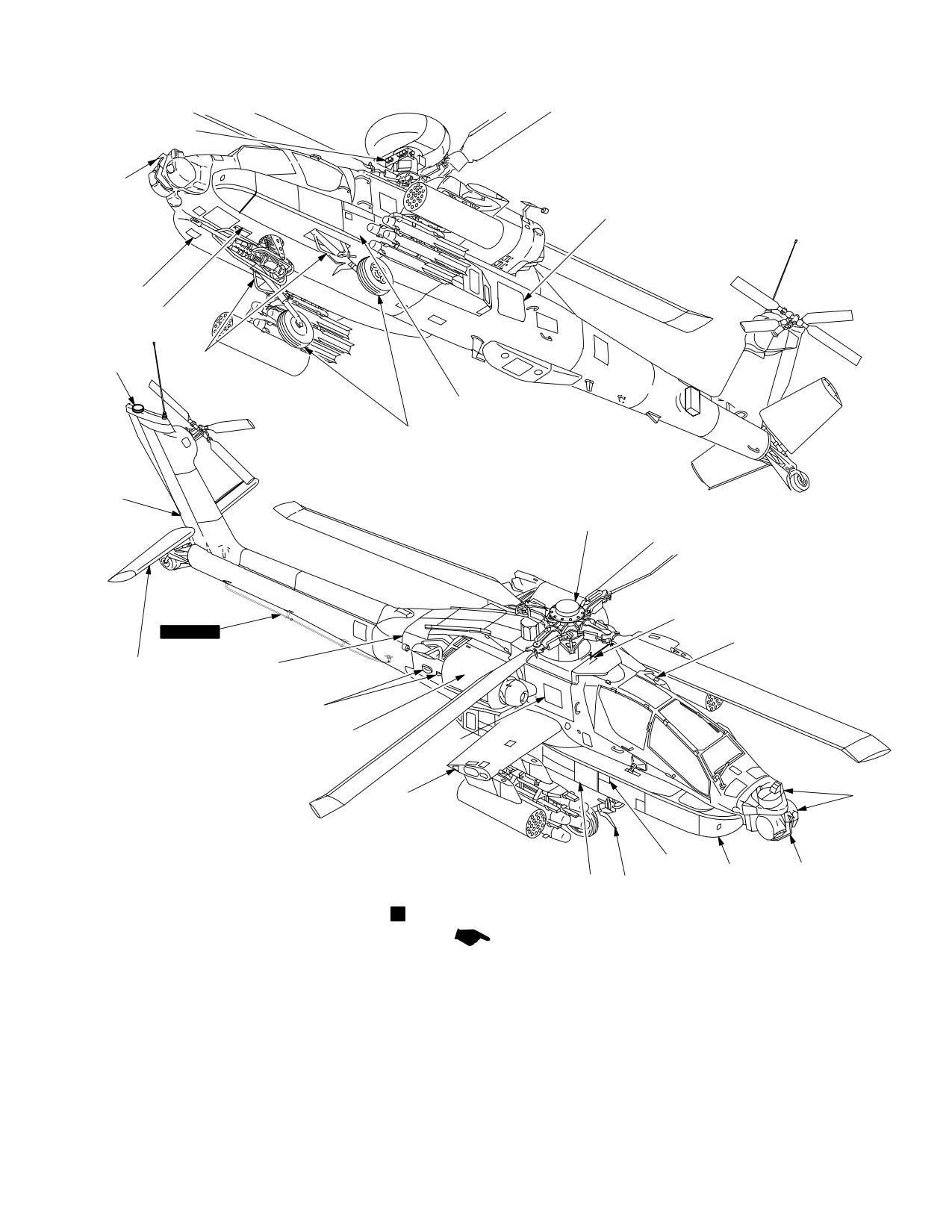
Figure 2-1 depicts the general arrangement of the
Left and right wings are attached to the center fuselage.
AH-64D Apache helicopter including access panels and
Each wing provides two hard points for external stores py-
major exterior components
lons with hydraulic and electrical quick-disconnects.
2.4 FUSELAGE
2.8 SPECIAL MISSION KITS
The fuselage includes a forward, center, and aft section.
The helicopter can be equipped with a Longbow kit, in-
All major weight items (crew, fuel, and ammunition) are
frared (IR) jammer kit, radar jammer kit, radar warning kit,
supported by bulkheads, frames, and a longitudinal sup-
laser warning kit, winterization kit, chaff kit, and extended
port structure. The forward fuselage section contains a
range kit.
portion of the Extended Forward Avionics Bays (EFAB),
and the CPG station. The Target Acquisition and Designa-
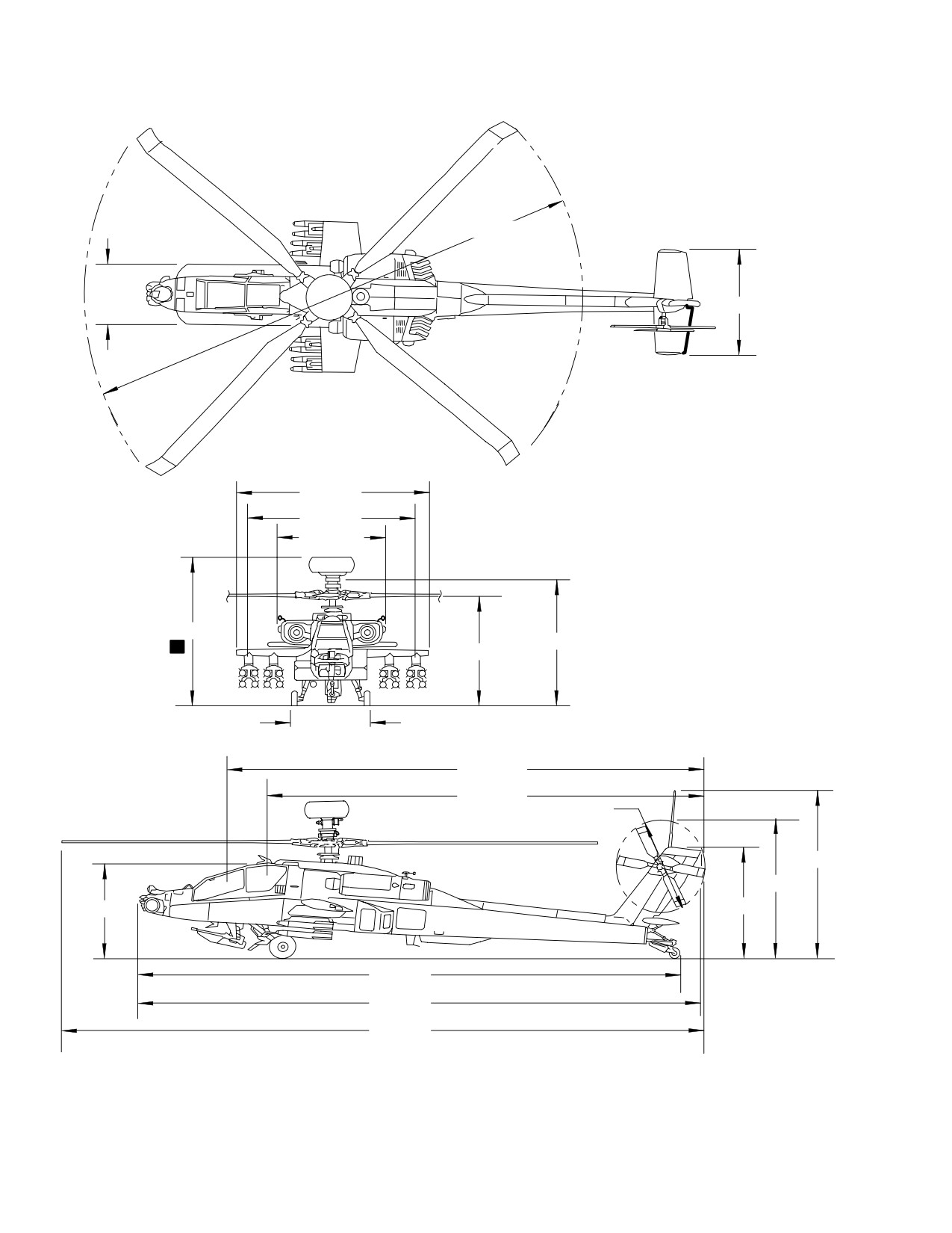
2.9 PRINCIPLE DIMENSIONS
tion Sight (TADS), Pilot Night Vision Sensor (PNVS), and
a 30mm area weapon are also mounted to this section.
Figure 2-2 illustrates principle helicopter dimensions.
The center fuselage contains a portion of the EFAB, the
pilot station, and provides support for the main landing
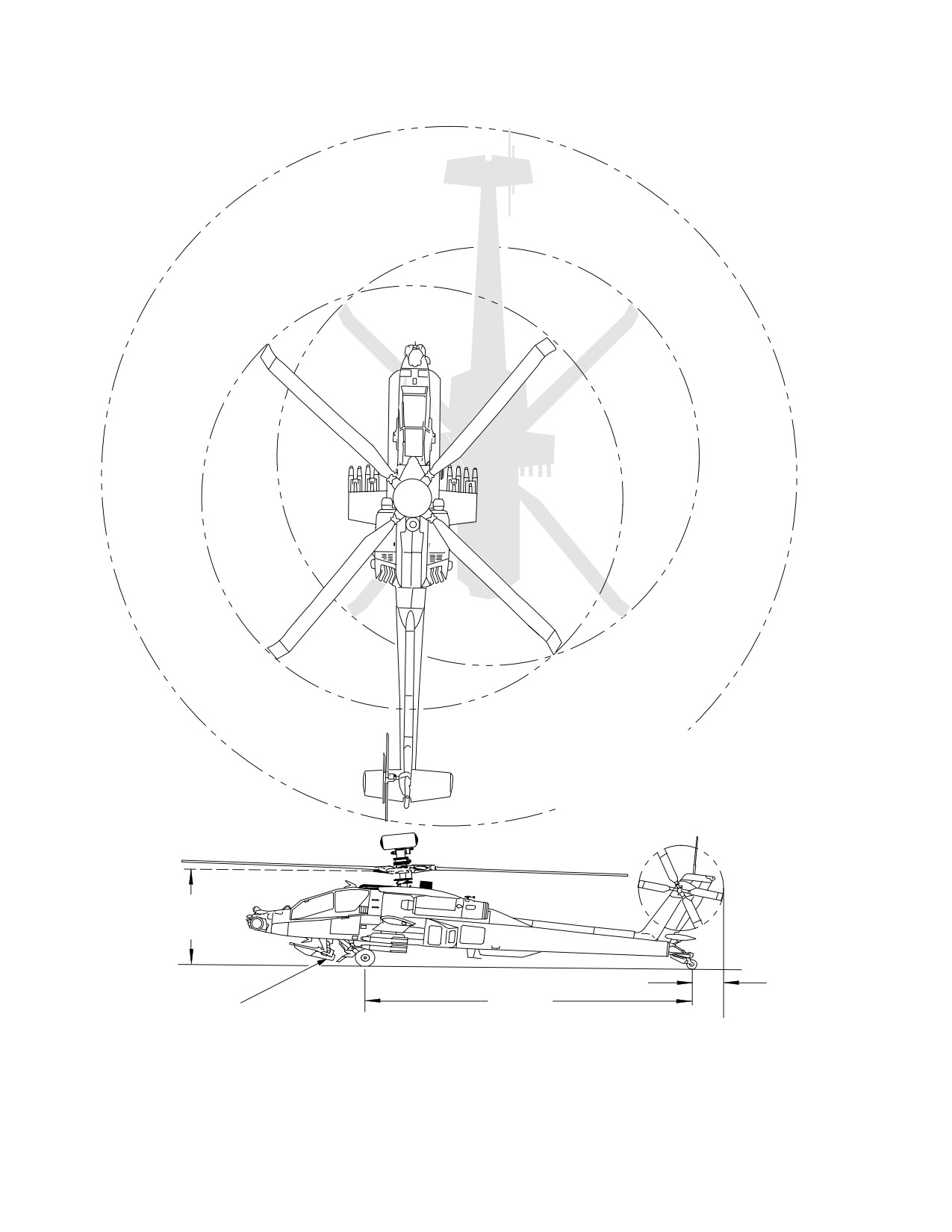
2.10 TURNING RADIUS AND GROUND CLEARANCE
gear, main transmission, wings, fuel cells, and ammuni-
tion bay. The aft fuselage section includes the vertical sta-
Figure 2-3 illustrates helicopter turning radius and ground
bilizer and mounts the tail landing gear. The aft avionics
clearance.
Use or disclosure of this information is subject to the restriction(s) on the title page of this document.
2-1
TM 1-1520-251-10
3
4
15
2
5
3
1
14
6
7
3
16
BLK 2
3
13
11
3
8
10
14
9
12
3
1. SURVIVAL EQUIPMENT STORAGE BAY
9. CANOPY JETTISON HANDLE ACCESS DOOR2
2. AFT AVIONICS BAY ACCESS DOOR
10. CHAFF DISPENSER
3. WIRE STRIKE PROTECTION SYSTEM (WSPS)
11. MAST MOUNTED ASSEMBLY (MMA)
L
4. CPG DOOR
12. LEFT SIDE EXTENDED FORWARD AVIONICS BAY (EFAB)
5. PILOT DOOR
13. IR JAMMER
6. SEARCHLIGHT
14. LASER WARNING SENSORS
7. AMMUNITION BAY ACCESS DOOR
15. AIR DATA SYSTEM (ADS) SENSOR
8. TAIL LANDING GEAR
16. RIGHT SIDE EXTENDED FORWARD AVIONICS BAY (EFAB)
LBA0001A
Figure 2-1. General Arrangement (Sheet 1 of 2)
Use or disclosure of this information is subject to the restriction(s) on the title page of this document.
2-2
Change 2
TM 1-1520-251-10
17
3
18
20
3
3
31
35
19
30
33
32
BLK 2
3
29
28
27
26
25
24
21
23
22
3
34
3
17. RADAR FREQUENCY INTERFEROMETER (RFI)
L
27. ANTICOLLISION LIGHTS AND NAVIGATION LIGHTS
18. AFT STORAGE BAY
28. HYDRAULIC GROUND SERVICE PANEL ACCESS DOOR
19. MAIN LANDING GEAR
29. HORIZONTAL STABILATOR
20. UTILITY LIGHT AND GROUND POWER OUTLET ACCESS DOOR
30. VERTICAL STABILIZER
21. TADS/PNVS TURRET
31. GLOBAL POSITIONING SYSTEM (GPS) ANTENNA
22. RIGHT SIDE EFAB
32. ICE DETECT PROBE
23. FIRE EXTINGUISHER ACCESS DOOR
33. FLAT PLATE (FCR REMOVED)
24. INTERCOMMUNICATIONS ACCESS DOOR
34. RIGHT FLYAWAY KIT BAY
25. TRANSMISSION ACCESS DOOR
35. LEFT FLYAWAY KIT BAY
26. ENGINE NACELLE ASSEMBLY
LBA0002B
Figure 2-1. General Arrangement (Sheet 2 of 2)
Use or disclosure of this information is subject to the restriction(s) on the title page of this document.
Change 4
2-3
TM 1-1520-251-10
48 FT DIA
6 FT 10 IN
11 FT 2 IN
16 FT 4 IN
15 FT 6 IN
9 FT 11 IN
16 FT 1 IN
13 FT 4 IN
L
11 FT 10 IN
6 FT 8 IN
43 FT 11 IN
38 FT 11 IN
9 FT 2 IN. DIA
17 FT 6 IN
14 FT 1 IN
9 FT 2 IN
11 FT 8 IN
48 FT 2 IN
49 FT 1 IN
57 FT 8 IN
LBA0006
Figure 2-2. Principle Helicopter Dimensions
Use or disclosure of this information is subject to the restriction(s) on the title page of this document.
2-4
TM 1-1520-251-10
TURNING RADIUS:
37 FT 6 IN
NOTE:
GROUND CLEARANCE
30mm GUN, STOWED 12.0 IN.
CLEARANCE IS REDUCED IF WIRE STRIKE
PROTECTION SYSTEM IS INSTALLED.
ROCKET LAUNCHER, GROUND STOW 25.0 IN
MISSILE LAUNCHER, UNLOADED RAIL 27.0 IN
MISSILE LAUNCHER, LOADED RAIL
18.0 IN
7FT 11 IN (MIN)
AT MAXIMUM
DROOP
2 FT 9 IN.
34 FT 9 IN.
(NOTE)
LBA0007
Figure 2-3. Turning Radius and Ground Clearance
Use or disclosure of this information is subject to the restriction(s) on the title page of this document.
2-5
TM 1-1520-251-10
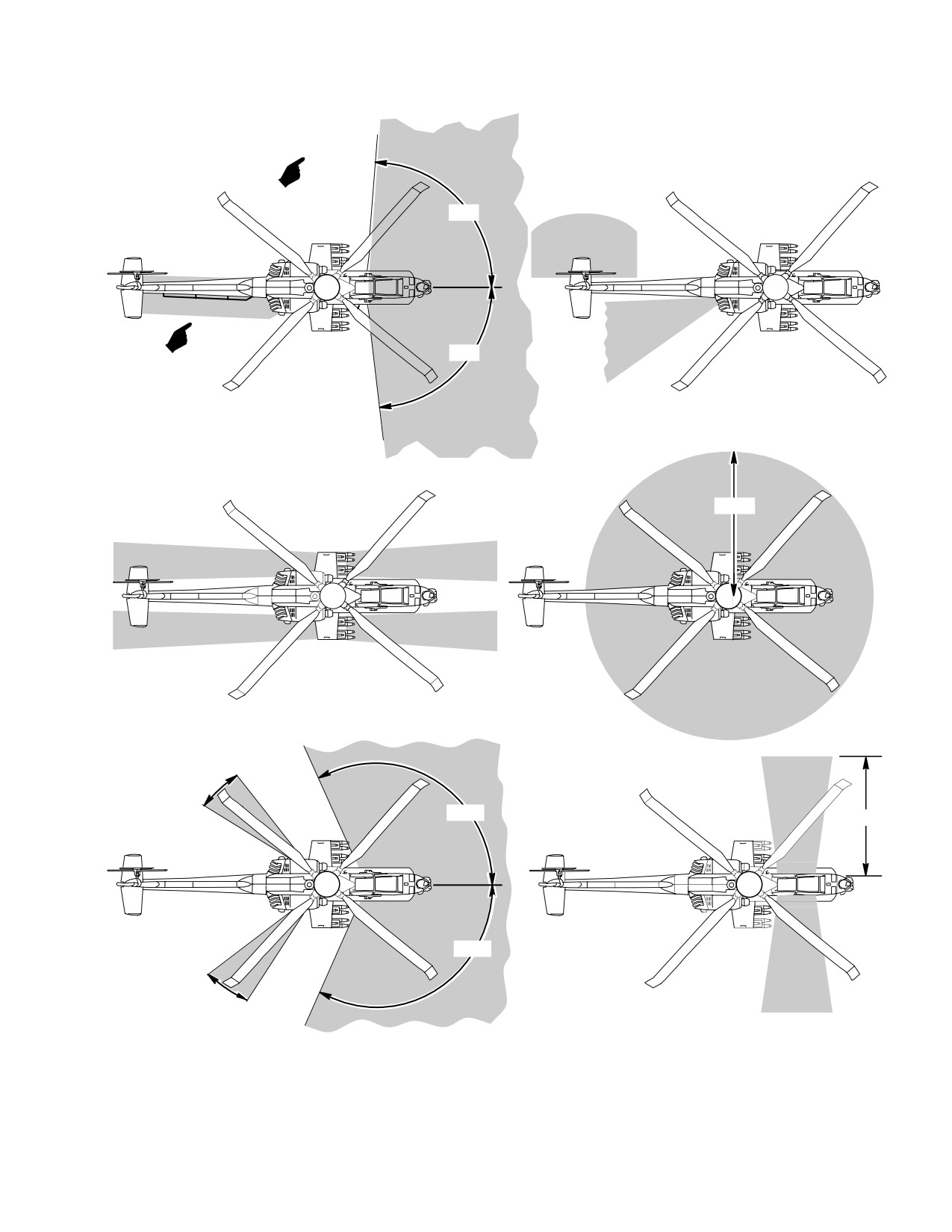
2.11 DANGER AREAS
2.11.4 During Canopy Jettison. Acrylic fragments will
be propelled up to 50 feet from the helicopter. Personnel
Figure 2-4 illustrates aircraft danger areas as described in
approaching a crash damaged helicopter must look for a
the following subparagraphs:
signal from the crew that closer approach is safe.
2.11.1 Approaching Operating Aircraft. Personnel
2.11.5 Laser. The laser must be given special safety
approaching an operating helicopter shall do so at a 45°
considerations because of extreme danger involved dur-
angle from the front. The approach shall be made from
ing its operation. Relatively low laser light levels can
well outside the rotor disc area until recognition is re-
cause permanent damage to eyes and skin burns.
ceived from the pilot. The pilot will signal when closer ap-
proach is safe.
2.11.6 Environmental Control System Exhaust. High
temperature, high velocity air is exhausted from the rear
2.11.2
Tail Rotor Air Flow and Main Rotor Down-
of both EFABS. Personnel should remain clear of these
wash. When the helicopter is in a hover or operating at
exhaust areas when working on or around the helicopter.
takeoff power, the downwash and airflow may be danger-
ous even outside the turning radius of the helicopter.
2.11.7
[
BLK 2
HF Radio Antenna. Personnel
2.11.3 Exhaust Gases. Personnel should remain clear
should remain at least five feet away from the HF radio an-
of areas exposed to exhaust gases (i.e. helicopter en-
tenna while the radio is transmitting. High levels of electro-
gines and APU). Severe burns may result from exposure
magnetic radiation are emitted by this antenna while
to these areas.
transmitting.]
Use or disclosure of this information is subject to the restriction(s) on the title page of this document.
2-6
Change 2
TM 1-1520-251-10
30MM GUN AREA & BLOCK 2 HF ANTENNA
APU EXHAUST AREA & TAIL ROTOR AREA
89°
89°
ENGINE EXHAUST AND ROTOR DISC AREA
HELLFIRE AND ROCKET AREA
25 FT
ECS BLOWER EXHAUST AND LASER AREA
CANOPY JETTISON AREA
20°
110°
50 FT
110°
20°
LBA0008A
Figure 2-4. Danger Areas
Use or disclosure of this information is subject to the restriction(s) on the title page of this document.
Change 2
2-7
TM 1-1520-251-10
2.12 CREWSTATIONS
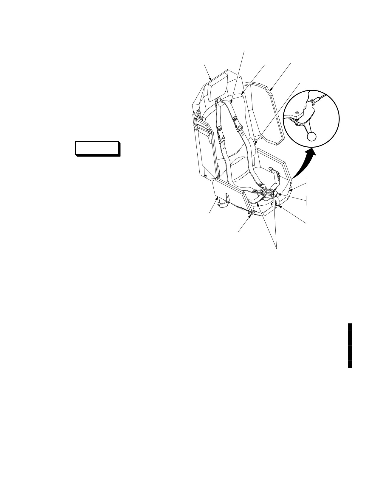
SHOULDER HARNESS
BACK
HEADREST
CUSHION
ARMORED WING
The crewstations are arranged in tandem and are sepa-
LUMBAR
rated by a ballistic shield. The pilot station is aft of the
SUPPORT
CPG station. Handholds and steps permit the crew to en-
CUSHION
ter and exit on the right side of the helicopter. A canopy
covers both crew stations. The canopy frame and trans-
parent ballistic shield form a rollover structure. Armored
INERTIA
seats, installed in both crew stations, provide maximum
REEL
survivability and minimum vulnerability.
LOCK
LEVER
2.13 CREWMEMBER SEATS
WARNING
Seats stroke downward during a crash,
and any obstruction may increase the
possibility of injury. Items shall not be
SEAT
CUSHION
placed beneath seats.
RESTRAINT
SYSTEM
The pilot and CPG seats (fig 2-5) provide ballistic protec-
tion. They are adjustable for height only. The seats are
ARMORED SEAT
one-piece armored seats equipped with back, seat, and
BUCKET
lumbar support cushions. Each seat is equipped with a
CROTCH
shoulder harness, lap belt, crotch belt, and inertial reel.
VERTICAL ADJUST
BELT
CONTROL HANDLE
The shoulder harness and belts have adjustment fittings
and come together at a common attachment point. This
LAP
provides a single release that can be rotated either clock-
BELTS
LBA0016
wise or counterclockwise to simultaneously release the
shoulder harness and all belts.
Figure 2-5. Crewmember Seat (Both Crew Stations)
NOTE
Seat height should be adjusted to the bore-
sight position for all flight operations. View-
2.13.2 Inertia Reel Operation. A two position shoulder
ing the MPD when the seat is not in the
harness inertia reel lock lever is installed on the left front
boresight position (or from outside the
of each seat. When the lever is in the aft position, the
crewstation) can result in presentation of
shoulder harness lock will engage with an acceleration of
MPD symbol color changes, as well as re-
6 Gs in any direction and/or if the webbing is exposed to
duced quality or distortion of MPD video in-
an acceleration of 2-1/2 Gs or greater. In the forward posi-
formation. The MPD viewing cone accom-
tion, the shoulder harness lock assembly is firmly locked.
modates normal body movement when the
Whenever the inertia reels lock because of deceleration
seat is adjusted to the design eye position.
forces, they remain locked until the lock lever is placed in
forward and then aft positions.
2.13.1 Seat Height Adjustment. Vertical seat adjust-
ment is controlled by a lever on the right front of the seat
2.14 CONTROLS, DISPLAYS, INSTRUMENT PANELS
bucket. When the lever is pulled out (sideways), the Pilot
AND CONSOLES
seat can be moved vertically approximately 5 inches and
locked at any 5/8 inch interval, the CPG can be moved
vertically approximately 3 3/4 inches and locked at any 5/8
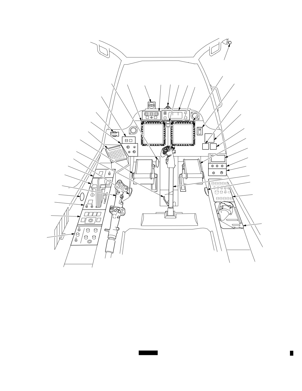
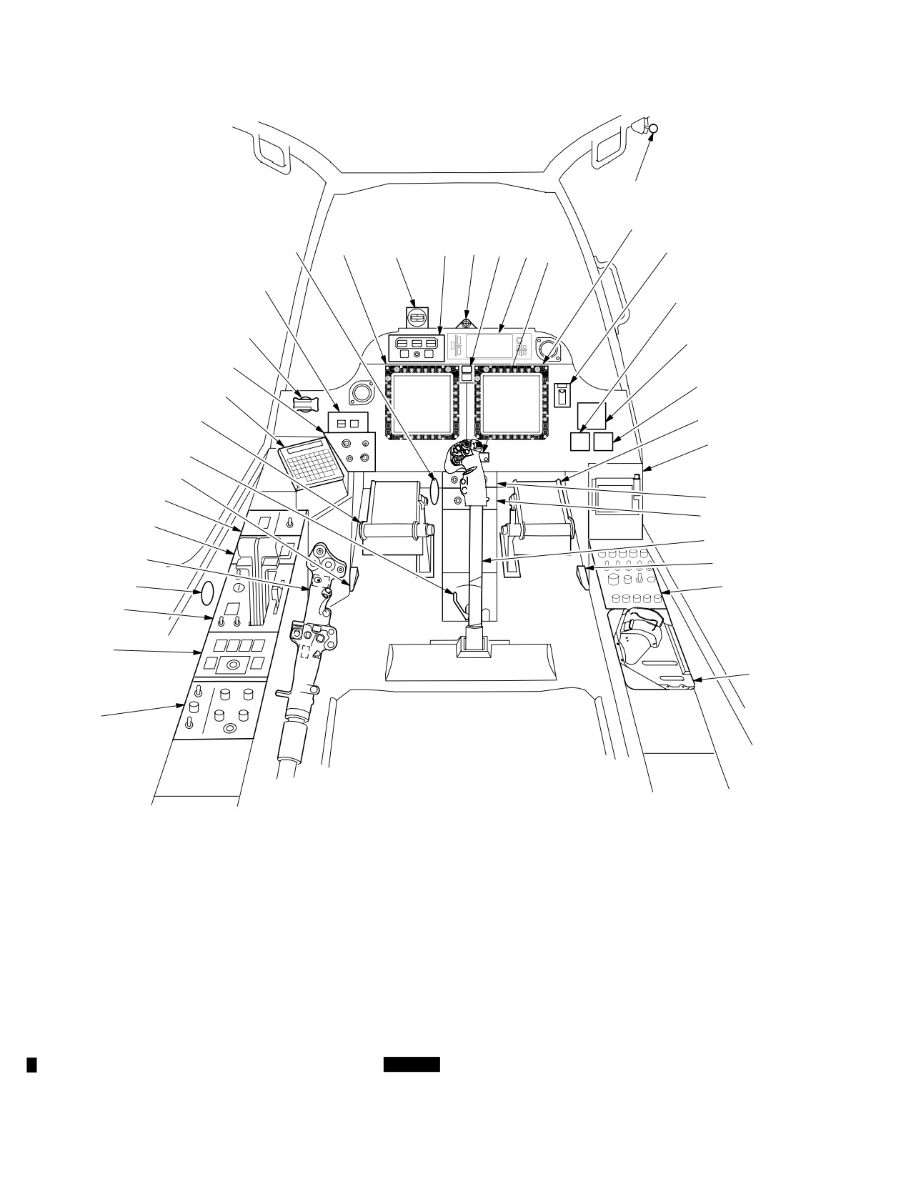
Figures 2-6 and 2-7 provide an overview of controls, dis-
inch interval. Springs counterbalance the weight of the
plays, and instrumentation in both crew stations. Individu-
seat. The lever returns to the locked position when re-
al controls, displays, and instruments will be discussed
leased.
with their associated systems.
Use or disclosure of this information is subject to the restriction(s) on the title page of this document.
2-8
Change 2
TM 1-1520-251-10
1
2
28
2
30
29
31
32
33
3
34
27
4
26
5
25
6
24
7
7
8
23
22
9
21
10
20
11
12
19
18
13
17
16
14
15
1. CANOPY DOOR RELEASE LEVER
11. CYCLIC STICK
21.
TAIL WHEEL LOCK/
29. STANDBY COMPASS
2. MULTIPURPOSE DISPLAY UNIT
12. ICS SWITCH
NVS MODE PANEL
30. FIRE DETECTION/
3. MASTER ZEROIZE
13. COMMUNICATIONS PANEL
22.
PUSHTOTALK (PTT)
EXTENGUISHING PANEL
4. AIRSPEED INDICATOR
14. HDU STORAGE
SWITCH
31. BORESIGHT RETICLE UNIT
5. ATITUDE INDICATOR
15. EXTERIOR/INTERIOR LIGHTING
23.
PEDAL ADJUST LEVER
32. MASTER WARNING/
6. ALTIMETER
PANEL
24.
KEYBOARD UNIT
MASTER CAUTION
7. DIRECTIONAL CONTROL PEDALS
16. STORES JETTISON PANEL
25.
VIDEO PANEL
LIGHTED PUSHBUTTONS
8. DATA TRANSFER
17. POWER LEVER QUADRANT
26.
CANOPY JETTISON
33. UP FRONT DISPLAY
CARTRIDGE RECEPTACLE
18. FREE AIR TEMPERATURE GAGE
HANDLE
34. RADIO CALL PLACARD
9. CHECK OVERSPEED TEST/
19. COLLECTIVE STICK
27.
ARMAMENT PANEL
GENERATOR RESET PANEL
20. EMERGENCY PANEL
28.
PARKING BRAKE HANDLE
10. WINDSHIELD WIPER CONTROL PANEL
LBA0455
Figure 2-6.
[
BLK 1
Pilot Station Diagram]
Use or disclosure of this information is subject to the restriction(s) on the title page of this document.
Change 2
2-9
TM 1-1520-251-10
1
2
28
2
30
29
31
32
33
3
34
27
4
26
5
25
6
24
7
7
8
23
22
21
9
10
20
11
19
12
18
13
17
16
14
15
1. CANOPY DOOR RELEASE LEVER
11. CYCLIC STICK
21.
TAIL WHEEL LOCK/
29. STANDBY COMPASS
2. MULTIPURPOSE DISPLAY UNIT
12. ICS SWITCH
NVS MODE PANEL
30. FIRE DETECTION/
3. MASTER ZEROIZE
13. COMMUNICATIONS PANEL
22.
PUSHTOTALK (PTT)
EXTENGUISHING PANEL
4. AIRSPEED INDICATOR
14. HDU STORAGE
SWITCH
31. BORESIGHT RETICLE UNIT
5. ATITUDE INDICATOR
15. EXTERIOR/INTERIOR LIGHTING
23.
PEDAL ADJUST LEVER
32. MASTER WARNING/
6. ALTIMETER
PANEL
24.
KEYBOARD UNIT
MASTER CAUTION
7. DIRECTIONAL CONTROL PEDALS
16. STORES JETTISON PANEL
25.
VIDEO PANEL
LIGHTED PUSHBUTTONS
8. DATA TRANSFER
17. POWER LEVER QUADRANT
26.
CANOPY JETTISON
33. ENHANCED UP FRONT DISPLAY
INIT
18. FREE AIR TEMPERATURE GAGE
HANDLE
34. RADIO CALL PLACARD
9. CHECK OVERSPEED TEST/
19. COLLECTIVE STICK
27.
ARMAMENT PANEL
GENERATOR RESET PANEL
20. EMERGENCY PANEL
28.
PARKING BRAKE HANDLE
10. WINDSHIELD WIPER CONTROL PANEL
LBA5065
Figure 2-6A.
[
BLK 2
Pilot Station Diagram]
Use or disclosure of this information is subject to the restriction(s) on the title page of this document.
2-10
Change 2
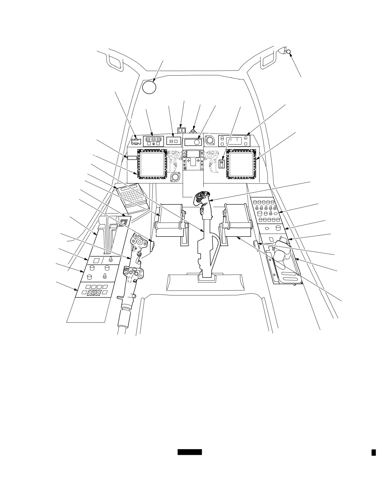
TM 1-1520-251-10
22
1
21
25
26
27
2
24
28
23
3
20
3
19
18
10
4
17
16
5
15
6
14
7
13
8
12
9
11
10
1. CANOPY DOOR RELEASE
11. STORES JETTISON PANEL
21.
CANOPY JETTISON HANDLE
2. UP FRONT DISPLAY
12. INTERIOR LIGHTING CONTROL PANEL
22.
REAR VIEW MIRROR
3. MULTIPURPOSE DISPLAY
13. TAIL WHEEL LOCK/NVS MODE PANEL
23.
FIRE DETECTION/EXTINGUISHING PANEL
4. CYCLIC STICK
14. COLLECTIVE STICK
24.
ARMAMENT PANEL
5. COMMUNICATIONS PANEL
15. POWER LEVER QUADRANT
25.
MASTER WARNING/MASTER CAUTION
6. WINDSHIELD WIPER CONTROL PANEL
16. PUSHTOTALK (PTT) SWITCH
LIGHTED PUSHBUTTONS
7. PROCESSOR SELECT PANEL
17. EMERGENCY PANEL
26.
BORESIGHT RETICLE UNIT
8. ICS SWITCH
18. KEYBOARD UNIT
27.
OPTICAL RELAY TUBE
9. HDU STORAGE
19. PEDAL ADJUST LEVER
28.
MASTER ZEROIZE
10. DIRECTIONAL CONTROL PEDALS
20. RADIO CALL PLACARD
LBA0456
Figure 2-7.
[
BLK 1
CPG Station Diagram]
Use or disclosure of this information is subject to the restriction(s) on the title page of this document.
Change 2
2-10.1
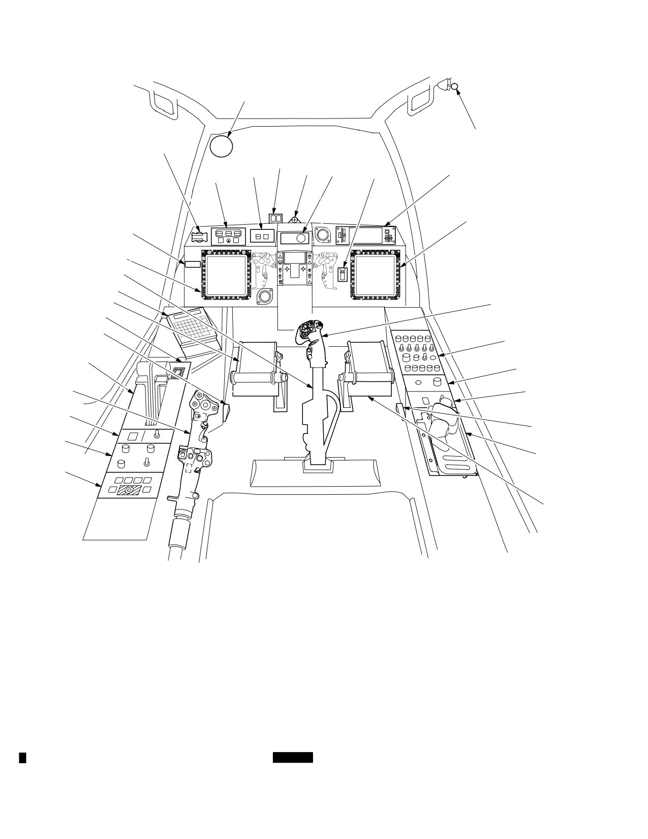
TM 1-1520-251-10
22
1
21
25
26
27
2
24
28
23
3
20
3
19
18
10
4
17
16
5
15
6
14
7
13
8
12
9
11
10
1. CANOPY DOOR RELEASE
11. STORES JETTISON PANEL
21.
CANOPY JETTISON HANDLE
2. ENHANCED UP FRONT DISPLAY
12. INTERIOR LIGHTING CONTROL PANEL
22.
REAR VIEW MIRROR
3. MULTIPURPOSE DISPLAY
13. TAIL WHEEL LOCK/NVS MODE PANEL
23.
FIRE DETECTION/EXTINGUISHING PANEL
4. CYCLIC STICK
14. COLLECTIVE STICK
24.
ARMAMENT PANEL
5. COMMUNICATIONS PANEL
15. POWER LEVER QUADRANT
25.
MASTER WARNING/MASTER CAUTION
6. WINDSHIELD WIPER CONTROL PANEL
16. PUSHTOTALK (PTT) SWITCH
LIGHTED PUSHBUTTONS
7. PROCESSOR SELECT PANEL
17. EMERGENCY PANEL
26.
BORESIGHT RETICLE UNIT
8. ICS SWITCH
18. KEYBOARD UNIT
27.
OPTICAL RELAY TUBE
9. HDU STORAGE
19. PEDAL ADJUST LEVER
28.
MASTER ZEROIZE
10. DIRECTIONAL CONTROL PEDALS
20. RADIO CALL PLACARD
LBA5066
Figure 2-7A.
[
BLK 2
CPG Station Diagram]
Use or disclosure of this information is subject to the restriction(s) on the title page of this document.
2-10.2
Change 2
TM 1-1520-251-10
2.15 MAIN LANDING GEAR
• Prevent swivel during operation on slopes.
Each main landing gear support consists of a trailing arm
and a nitrogen/oil shock strut. The trailing arms transfer
the helicopter landing and static loads to the airframe, and
the shock struts absorb vertical loads. The upper ends of
the left and right trailing arms attach to a cross tube which
passes through the fuselage and is supported by fuselage
anchored pivot bearings. The upper ends of the shock
struts are attached to mounts on the fuselage structure. In
addition to its normal energy absorbing function, each
ÓÓÓ
shock strut has a one time high impact absorbing feature.
Its shear rings are sheared and a rupture disc bursts caus-
ÓÓÓ
ing a controlled collapse of the strut.
ÓÓÓ
ÓÓÓ
2.16 TAIL LANDING GEAR
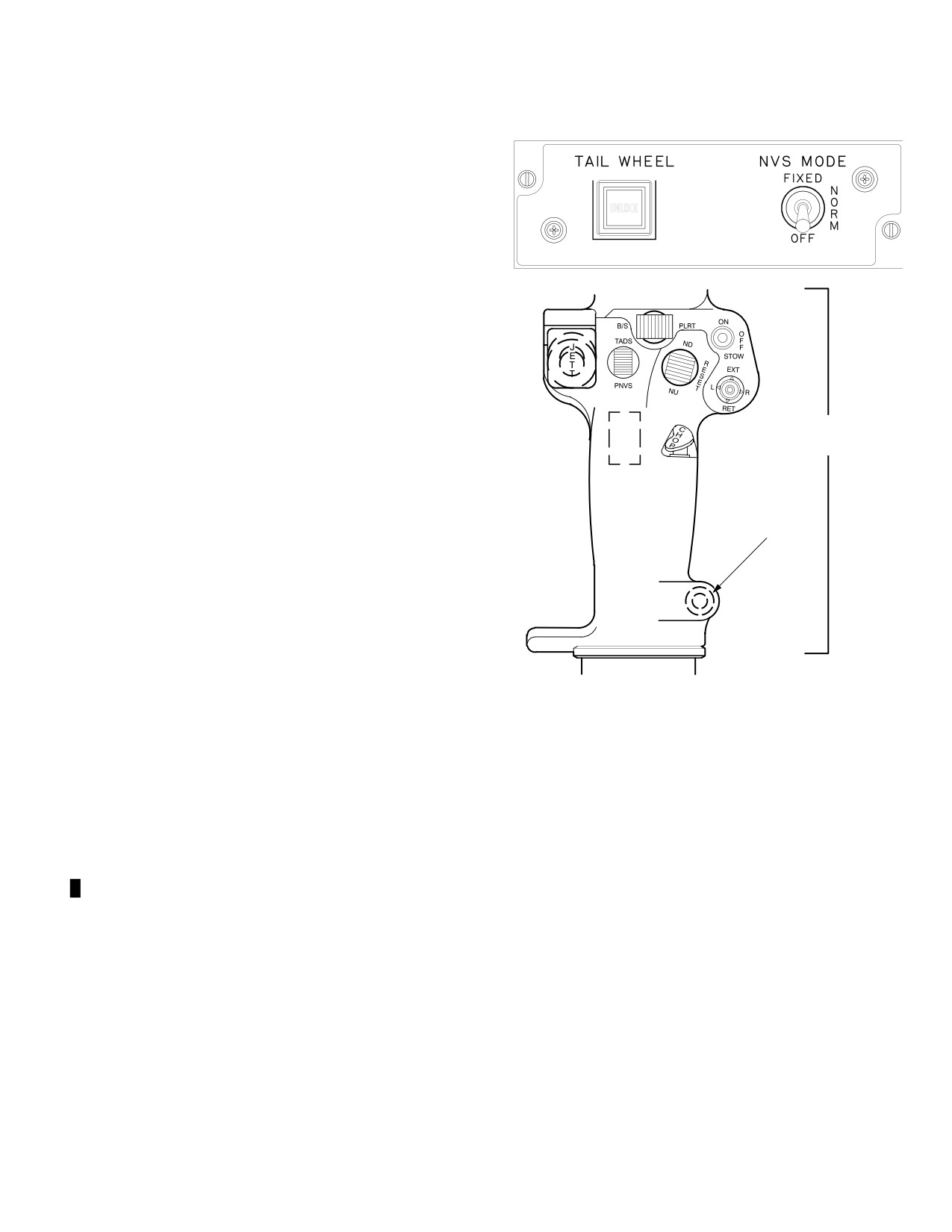
FLIGHT
CONTROL
GRIP
The tail landing gear consists of two trailing arms, nitro-
gen/oil shock strut, fork, axle, and wheel. The shock strut
has an impact absorbing capability similar to that of the
main landing gear shock strut. The tail wheel is 360° free
TAIL WHEEL
LOCK/UNLOCK
swiveling for taxiing and ground handling. The tail landing
gear system incorporates a spring loaded tail wheel lock.
The tail landing gear is hydraulically unlocked from the
crew station or manually locked/unlocked by a ground
crew using a handle attached to the actuator. The tail
wheel unlock system is actuated by hydraulic pressure
from the utility hydraulic system. Pressure is routed to the
actuator through a control valve located in the tail boom.
LBA1053
The valve is controlled by lock/unlock switches on the
TAIL WHEEL panel and collective flight control grip (fig
Figure 2-8.
Tail Wheel Lock/Unlock Switches
2-8). The tail wheel lock/unlock switches are alternate ac-
tion pushbutton switches. Pressing a switch energizes the
unlock actuator and retracts the locking pin. On the TAIL
2.17 LANDING GEAR BRAKES
WHEEL panel, the pushbutton illuminates to indicate UN-
LOCK. Pressing a pushbutton again de-energizes the un-
The brake system affects only the main landing gear
lock actuator and allows spring force to insert the lock pin
wheels. The main landing gear system consists of two in-
when the tail wheel is aligned to center position (the UN-
dependent hydromechanical systems, one left and one
LOCK pushbutton light will be extinguished). When the
right. Braking action is initiated from either station by ap-
aircraft is on the ground, an advisory message is dis-
plying foot pressure at the top portion of the directional
played on the UFD/EUFD to indicate the commanded
control pedals. This activates a master cylinder attached
state of the switch: T/W UNLK SEL or T/W LOCK SEL.
to each brake pedal. The master cylinders pressurize hy-
Switch annunciation and system status is simultaneous in
draulic fluid in the master cylinder system components.
both crew stations. If the tail wheel is unlocked manually,
This pressure is transmitted through tubing to the transfer
it can be locked from the either crewstation by pressing a
valves, and the parking brake valve, to the wheel brake
tail wheel lock/unlock switch. The tail wheel is locked to:
assemblies. It actuates pistons in each wheel brake as-
sembly causing friction linings to move against a floating
• Absorb rotor torque reaction during rotor brake
brake disk to stop wheel rotation. When the helicopter is
operation.
parked, the pilot or CPG applies and maintains pressure
• Prevent shimmy during rolling takeoffs and land-
on the brakes until the PARK BRAKE handle can be
ings.
pulled out by the pilot to set the parking brakes. When the
• Prevent swivel during ground operation in high
brake pressure is released, the handle can be released. If
winds.
the handle remains out, the parking brakes should be set.
Use or disclosure of this information is subject to the restriction(s) on the title page of this document.
Change 2
2-11
TM 1-1520-251-10
If the PARK BRAKE handle (fig 2-6) is pulled out without
2.19.2 Channel 2. The primary SP also serves as the
pressure applied to the brake pedals, the PARK BRAKE
bus controller for Channel 2 which integrates the naviga-
handle may remain out but the brakes will not be set. Hy-
tion and flight control equipment, as well as the Radar
draulic pressure is maintained in the system by the com-
Warning Receiver and Data Transfer Unit. In addition, the
pensator valves mounted on the parking brake valve. Ei-
Weapon Processors (WPs) and Display Processors
ther station can release the parking brake by exerting
(DPs) are remote terminals on Channel 2 which allows
pressure at the top of the directional control pedals.
data transfer between the SP, DP, and WP.
2.18 WINDSHIELD AND CANOPY
2.19.3 Channel 3. The primary WP serves as the bus
controller for Channel 3. The secondary WP monitors the
bus traffic to maintain coordination with the primary WP
The windshield consists of two heated, laminated glass
such that in the event of a failure the secondary WP can
windshields. One is directly forward of the CPG; the other
take over as primary. Channel 3 integrates the weapons
is directly above his head. The canopy consists of five
and sight subsystems.
acrylic panels: two on each side of the crew stations and
one directly above the pilot. The two canopy panels on the
right side are independently hinged. They latch and un-
2.19.4
Channel 4. Channel 4 is dedicated to data
latch separately by interior and exterior handles. They
transfer between the Fire Control Radar related equip-
swing upward and outward to provide entrance to, and
ment, including the Radar Frequency Interferometer.
exit from, the pilot/CPG crew stations. Failure to properly
close either canopy will cause an advisory message to ap-
2.19A [
BLK 2
FIBRE CHANNEL BUSES ]
pear on the Up Front Display (UFD)/Enhanced Up Front
Display (EUFD). The two canopy panels on the left side
are fixed and do not open. Refer to Section II of this chap-
The fibre channel buses are employed for transfer of data
ter for information about the canopy jettison system.
(especially large files) between the various elements of the
avionics system. Each bus is redundant, for failure and dam-
age tolerance, and consists of a primary and secondary bus
2.19 MIL-STD-1553B MULTIPLEX (MUX) BUSES
routed separately within the aircraft. Figure 2-9 depicts the
Fibre Channel bus architecture showing how the avionics
components are connected to the Fibre channels.
MIL-STD-1553B MUX bus channels are employed for
transfer of data between the various elements of the
avionics system. Each channel is redundant, for failure
2.19A.1 Fibre Channel Data Bus Loop. The System,
and damage tolerance, and consists of a primary and sec-
Weapon, and Display processors are connected to this fibre
ondary bus routed separately within the aircraft. MIL-
channel bus. This fibre channel bus is used to pass informa-
STD-1553B specifies a one megabit per second, serial,
tion between the processors. This fibre channel bus can
command/response, multi-access data bus which uses a
transmit 320 megabits per second. The processors are con-
bus controller, remote terminal command/response proto-
nected in an arbitrated loop fashion. The primary System
col. Figure 2-9 depicts the MUX bus architecture showing
Processor (SP) coordinates all message traffic and is used as
how the avionics components are connected to the MUX
the pass through for messages between the Display Proces-
channels. The redundant System, Weapon, and Display
sors. The mux bus connection must be established before
Processors are each connected to two bus channels to fa-
that processor can use the fibre channel bus.
cilitate control, monitoring, communications, and proces-
sing functions. The avionics are connected to the MUX
2.19A.2 DP/DTU Point to Point Fibre Channel Data
buses in a manner which assigns related equipment to a
Bus. Each Display Processor (DP) has a fibre channel
common bus.
connection with the Data Transfer Unit (DTU). This fibre
channel bus is used to pass data to and from the DTU. This
2.19.1
Channel 1. The primary System Processor
fibre channel bus can transmit 1024 megabits per second
(SP) serves as the bus controller for Channel 1. The sec-
(but may be limited by the transfer rate of the specific DTC).
ondary SP monitors the bus traffic to maintain coordina-
Mission data files are uploaded from one of the DPs and
tion with the primary SP such that in the event of a failure
passed to the appropriate processor over the fibre channel
the secondary SP can take over as the primary. Channel
data bus loop. Mission files are downloaded to the DTU in a
1 is used to integrate the communications, electrical, key-
similar fashion. Map data files are uploaded independently for
board, and display systems.
each DP.
Use or disclosure of this information is subject to the restriction(s) on the title page of this document.
2-12
Change 2
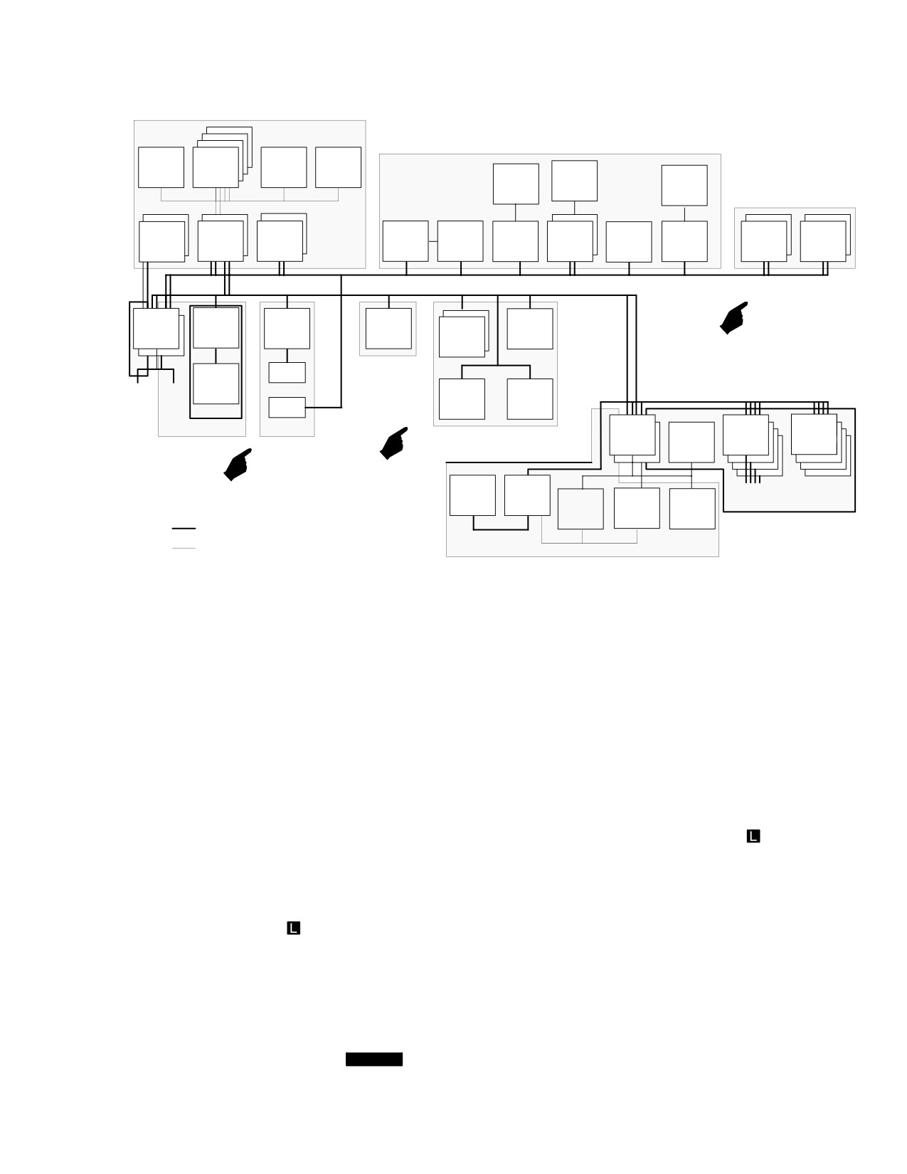
TM 1-1520-251-10
CONTROL AND DISPLAYS
COMM/IDENT
ORT
MPD
DEU
VCR
KY58
IFM
KIT
AIRCRAFT
1C
SYSTEMS
UHF
VHF
VHF
ECS
UFD
DP
KU
IDM
CIU
XPNDR
ELC
AM
FM
AM
DCU
MUX CH 1
MUX CH 2
SP
RWR
DTU
FMC
DRVS
EGI
FLIGHT
DTC
CONTROLS
LWR
MUX CH 3
IRJ
ADF
HADS
AIRCRAFT
RLWR
MDR
RJAM
SYSTEMS
CHAFF
HELLFIRE
NAVIGATION
WP
PIU
LAUNCHERS
GUN
ASE
DATA MGMT
RFI
FCR
ROCKET
TADS
PNVS
SEU
WEAPONS
MUX, DIRECT I/O
MUX CH 4
EIA/RS343A
VIDEO TO DP
SIGHTS
LBA0483B
LEGEND
ASE
AIRCRAFT SURVIVABILITY EQUIPMENT
KU
KEYBOARD UNIT
CIU
COMMUNICATIONS INTERFACE UNIT
KY58
ENCRYPTER/DECRYPTER DEVICE
DCU
DATA CONTROL UNIT
LWR
LASER WARNING RECEIVER
DEU
DISPLAY ELECTRONICS UNIT
MPD
MULTIPURPOSE DISPLAY
DP
DISPLAY PROCESSOR
ORT
OPTICAL RELAY TUBE
DRVS
DOPPLER RADAR VELOCITY SENSOR
PIU
PYLON INTERFACE UNIT
DTC
DATA TRANSFER CARTRIDGE
PNVS
PILOT NIGHT VISION SENSOR
DTU
DATA TRANSFER UNIT
RFI
RADAR FREQUENCY INTERFEROMETER
ECS
ENVIRONMENTAL CONTROL SYSTEM
RJAM
RADAR JAMMER
EMBEDDED GLOBAL POSITIONING INERTIAL NAVIGATION
EGI
RWR
RADAR WARNING RECEIVER
SYSTEM
ELC
ELECTRICAL LOAD CONTROLLER
SEU
SIGHT ELECTRONICS UNIT
EPMS
ELECTRICAL POWER MANAGEMENT SYSTEM
SP
SYSTEM PROCESSOR
FCR
FIRE CONTROL RADAR
TADS
TARGET ACQUISITION AND DESIGNATION SIGHT
FMC
FLIGHT MANAGEMENT COMPUTER
UFD
UP FRONT DISPLAY
HADS
HELICOPTER AIR DATA SYSTEM
VCR
VIDEO CASSETTE RECORDER
IDM
IMPROVED DATA MODEM
WP
WEAPONS PROCESSOR
IFM
IMPROVED FREQUENCY MODULATION
XPNDR
TRANSPONDER
IRJ
INFRARED JAMMER
Figure 2-9.
[
BLK 1
Mission Equipment Package Architecture]
Use or disclosure of this information is subject to the restriction(s) on the title page of this document.
Change 4
2-13
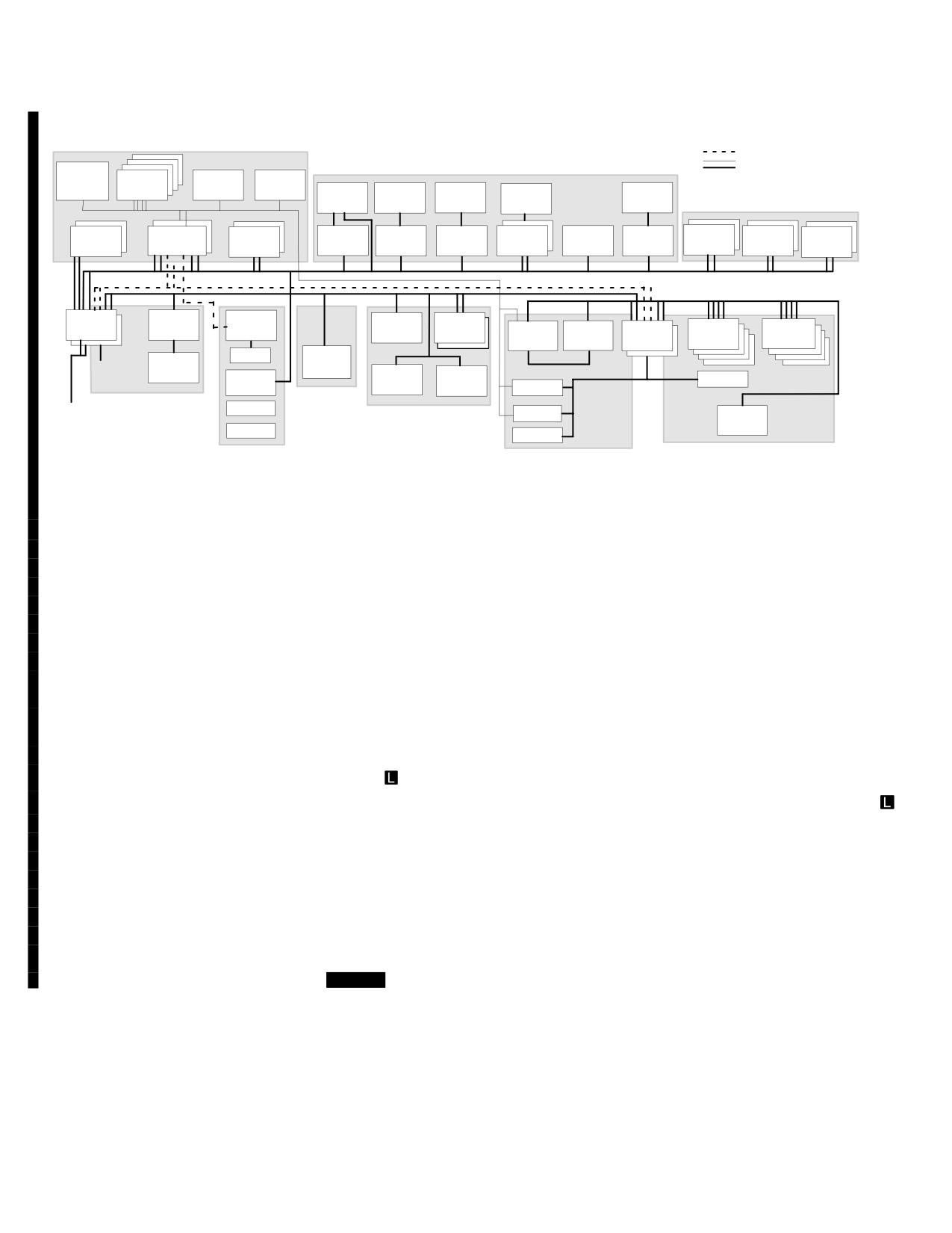
TM 1-1520-251-10
CONTROLS AND DISPLAYS
FIBRE CH
COMM/IDENT
EIA/RS343A
MUX, DIRECT I/O
ORT
MPD
DEU
VCR
CIU
KY100
KY58
IFM
KIT1C
AIRCRAFT SYSTEMS
EUFD
DP
KU
IDM
HF
UHF
FM
VHF
IFF
ECS
ELC
PCU
MUX CH 1
FIBRE CH
MUX CH 3
MUX CH 2
SP
RWR
DTU
DRVS
EGI
HELLFIRE
RFI
FCR
WP
PIU
LAUNCHER
PDTC
FMC
MUX CH 4
IRJ
LWR
RFJ
MDR
ADF
HADS
GUN
CHAFF
TADS
ASE
FLIGHT
AIRCRAFT
SPORT
CONTROLS
NAVIGATION
PVS
SYSTEMS
LEU
AMPS
SEU
WEAPONS
DATA MGMT
SIGHTS
LBA5163
LEGEND
ADF
AUTOMATIC DIRECTION FINDER
KIT1C
KIT1C ENCRYPTOR/DECRYPTOR DEVICE
ASE
AIRCRAFT SURVIVABILITY EQUIPMENT
KU
KEYBOARD UNIT
AMPS
AVIATION MISSION PLANNING STATION
KY100
KY100 ENCRYPTOR/DECRYPTOR DEVICE
CIU
COMMUNICATIONS INTERFACE UNIT
KY58
KY58 ENCRYPTOR/DECRYPTOR DEVICE
DEU
DISPLAY ELECTRONICS UNIT
LEU
LASER ELECTRONIC UNIT
DP
DISPLAY PROCESSOR
LWR
LASER WARNING RECEIVER
DRVS
DOPPLER RADAR VELOCITY SENSOR
MDR
MAINTENANCE DATA RECORDER
DTU
DATA TRANSFER UNIT
MPD
MULTIPURPOSE DISPLAY
ECS
ENVIRONMENTAL CONTROL SYSTEM
ORT
OPTICAL RELAY TUBE
EGI
EMBEDDED GPS/INERTIAL NAVIGATION UNIT
PDTC
PCMICA DATA TRANSFER CARTRIDGE
ELC
ELECTRICAL LOAD CONTROLLER
PCU
POWER CONTROL UNIT
EUFD
ENHANCED UP FRONT DISPLAY
PIU
PYLON INTERFACE UNIT
FCR
FIRE CONTROL RADAR
PNVS
PILOT NIGHT VISION SENSOR
FM
ARC201D RADIO
RFI
RADAR FREQUENCY INTERFEROMETER
FMC
FLIGHT MANAGEMENT COMPUTER
SEU
SIGHT ELECTRONICS UNIT
GUN
30MM AREA WEAPON SYSTEM
SP
SYSTEM PROCESSOR
HADS
HELICOPTER AIR DATA SYSTEM
SPORT
SOLDIER PORTABLE ONSYSTEM REPAIR TOOL
HF
ARC220 RADIO
TADS
TARGET ACQUISITION AND DESIGNATION SIGHT
IDM
IMPROVED DATA MODEM
UHF
ARC164 RADIO
IFF
IDENTIFICATION FRIEND OR FOE
VCR
VIDEO CASSETTE RECORDER
IFM
IMPROVED FREQUENCY MODULATION
VHF
ARC186 RADIO
IRJ
INFRARED JAMMER
WP
WEAPON PROCESSOR
Figure 2-9A.
[
BLK 2
Mission Equipment Package Architecture]
2.20
MULTIPURPOSE DISPLAY (MPD)
weapon systems during a mission. The MPD is a color ac-
tive matrix liquid crystal display (AMLCD) which presents
The MPD (fig 2-10) provides the capability for controlling
raster video images provided by the Display Processor
most of the avionics systems, and serves as the primary
(DP). The MPD is an interactive display through which
targeting display for the FCR. The MPD allows a crew-
systems can be controlled via bezel buttons or the re-
member to customize the way he monitors aircraft and
motely located cursor controllers. There are two MPDs in
Use or disclosure of this information is subject to the restriction(s) on the title page of this document.
2-14
Change 2
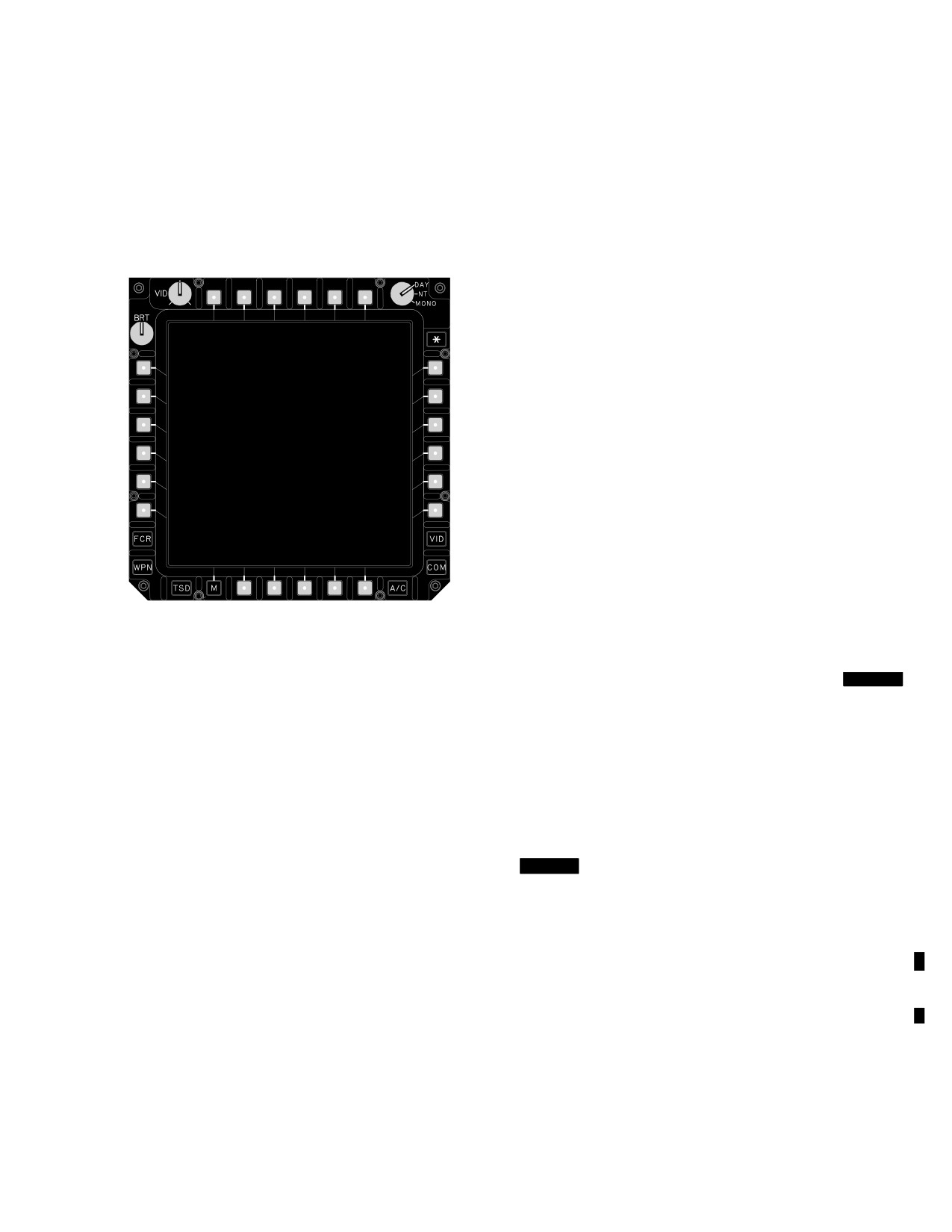
TM 1-1520-251-10
each crew station and they are supported by the AC pow-
touches will result in localized cooling of the glass, and a color
er bus. MPD interfaces with aircraft subsystems are de-
fingerprint at the location of the touch for a very short time.
scribed in the applicable sections of this manual. The ref-
This does not indicate that the displays are delicate, dam-
erence designators shown in figure 2-10; T1 - T6, L1 - L6,
aged, or easily damaged. The display surface is not soft. The
R1 - R6, and B1 - B6 are used throughout this manual to
displays will not be damaged by routine handling.
identify the respective MPD bezel button locations. B1 be-
zel button will always be the menu button.
2.20.4 Screen Save Mode. During ground operations
on external power with the throttles in the OFF position,
T 1
T 2
T 3
T 4
T 5
T 6
the displays will enter a screen save mode in which the
display backlight extinguishes if no button presses have
been received within 5 minutes. The display can be
brought out of screen save mode by selecting any button
on either display in that crewstation. Cursor and knob op-
L1
R1
erations will also interrupt the screen save mode.
L2
R2
2.20.5 MPD Viewability Controls. Each MPD has in-
L3
R3
dependent controls for adjustment of display image quali-
ty. Brightness (BRT), Video Enhancement (VID), and
L4
R4
DAY/NIGHT/MONO selections are provided. Brightness
L5
R5
is controlled locally by the MPD and is therefore unaf-
fected by single DP operations. The remaining functions
L6
R6
are impacted by single DP operations, as described be-
low.
a. Brightness (BRT) Control. The BRT control va-
ries the intensity of the display video and symbology. The
B1
B2
B3
B4
B5
B6
or
brightness range available is affected by the DAY/NIGHT/
Menu
LBA0459
MONO control selection.
Figure 2-10. Multipurpose Display
b. Video Enhancement (VID) Control.
[
BLK 1
The VID knob allows the crew to optimize the video on his
2.20.1
Eyewear Restrictions. MPDs emit polarized light.
MPD for a specific sensor or scene content. Leaving the
Polarized sunglasses should not be worn by the operator, be-
VID knob in the center detent position provides un - modi-
cause they could make the display appear black. Sunglasses
fied video. Rotating the VID knob clockwise brightens the
which preferentially block certain colors (such as yellow or
video, and can bring out information within dark areas.
green tint glasses) should not be used. Neutral density gray
Rotating the VID knob counterclockwise darkens the vid-
sunglasses are compatible with color displays. The MPDs
eo, and can bring out information within the bright areas.
are compatible with glasses and visors which protect against
During single DP operations, the video enhancement
the aircraft’s own laser. However, use of other laser protective
function uses a last - select logic.]
visors should not be attempted until their compatibility with all
[
BLK 2
When displaying a map underlay (on the TSD
MPD format colors has been established.
page), the VID knob controls the amount of attenuation on
the underlay. The attenuation allows for better visual sep-
2.20.2 Cleaning Restrictions. The MPDs should be
aration of the stick map symbols from the map underlay.
cleaned with a clean cotton cloth and alcohol. Ammonia -
Leaving the VID knob in the center detent position pro-
based cleaners shall not be used.
vides about 50% attenuation. Rotating the knob clockwise
decreases the attenuation (brightens the map underlay) to
2.20.3 Response To Touch. The MPDs will feel warm to
0%. Rotating the knob counterclockwise increases the at-
the touch during normal, proper operation. Crewmember
tenuation to 100%.]
Use or disclosure of this information is subject to the restriction(s) on the title page of this document.
Change 3
2-14.1
TM 1-1520-251-10
c. DAY/NIGHT/MONO Control. The DAY/NIGHT/
lit ambient or nighttime conditions. The NIGHT and
MONO control varies the operating range of the BRT con-
MONO modes provide an expanded lower dimming range
trols and the color mode. DAY operations provide MPD
to allow fine adjustment to accommodate various night-
white or green video and color symbols which can be used
time ambient and dark adaptation conditions. Backlight
from bright daytime ambient conditions to dim twilight am-
brightness control for DAY/NIGHT/MONO knob is not im-
bient conditions. NIGHT operations provide MPD white
pacted by single DP operation. However, color is im-
and green video and color symbols which can be used
pacted by single DP operation. If either MPD is set to
from completely dark to dimly lit or nighttime ambient
MONO, only green symbols and video will be available for
conditions MONO operations provide green video and
that MPD set. Otherwise, color symbols and white or
symbols which can be used from completely dark to dimly
green video will be available for that MPD set.
Use or disclosure of this information is subject to the restriction(s) on the title page of this document.
2-14.2
Change 2
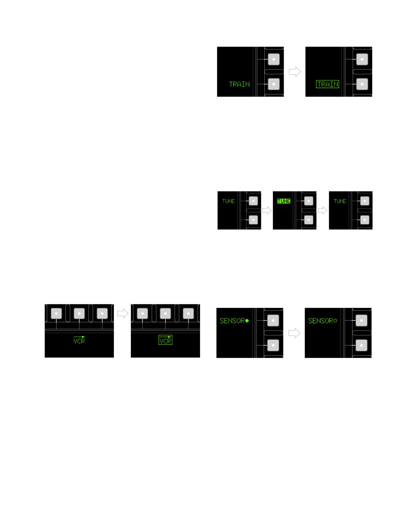
TM 1-1520-251-10
2.20.6 MPD Bezel Pushbutton Controls. The MPD
provides pushbuttons on the bezel perimeter used to se-
lect the page presented on the MPD, or to make selec-
tions or commands specified by the adjacent display text
label.
2.20.7 MPD Button Control Affect. MPD bezel push-
button control selections may have an aircraft/system
Operating Mode
Operating
wide affect, a crew station only affect, or a MPD only af-
Not Set
Mode Set
fect. For example, changes to the fuel system controls af-
LBA1939
fect the entire fuel system (aircraft), and controls/displays
in both crew stations. However, changing the map scale
Figure 2-12. Maintained Pushbutton Operation
on the TSD page affects only the control and display of the
map scale within that crew station on both MPDs. Controls
having an aircraft affect are referred to as common to both
c. Momentary Pushbuttons. Momentary pushbut-
crew stations. Controls having a crew station affect are re-
tons (fig 2-13) command the aircraft systems to perform
ferred to as independent in each crew station. Page but-
the action described by the text label.
ton selections have only a MPD affect. The page change
is reflected only on the MPD where the page pushbutton is
selected.
2.20.8 Interrupting a Process. If an MPD bezel push-
button is pressed to start a process, pressing an unrelated
MPD bezel button will abort the original process and the
new selection process is accepted. For example, if a data
Radio Tune in Progress
LBA1940
entry button is pressed, setting the KU for data entry, and
an unrelated MPD bezel pushbutton is selected, the data
Figure 2-13. Momentary Pushbutton Operations
entry process is aborted and the new selection is accept-
ed.
(1) On/Off Pushbuttons. On/Off pushbuttons (fig
a. Page Pushbuttons. Page pushbuttons (fig 2-11)
2-14) command hardware to be powered on or off, or to
are used to select the desired page on the MPD.
turn operating modes on or off.
VCR Page Presented
ON
OFF
LBA1941
LBA1938
Figure 2-14. On/Off Pushbutton Operation
Figure 2-11. Page Pushbutton Operation
b. Maintained Pushbuttons. Maintained pushbut-
(2) Two State Pushbuttons. Two state pushbut-
tons (fig 2-12 ) are used to set hardware or operating
tons (fig 2-15) are used to toggle hardware or operating
modes.
modes between one of two states.
Use or disclosure of this information is subject to the restriction(s) on the title page of this document.
2-15
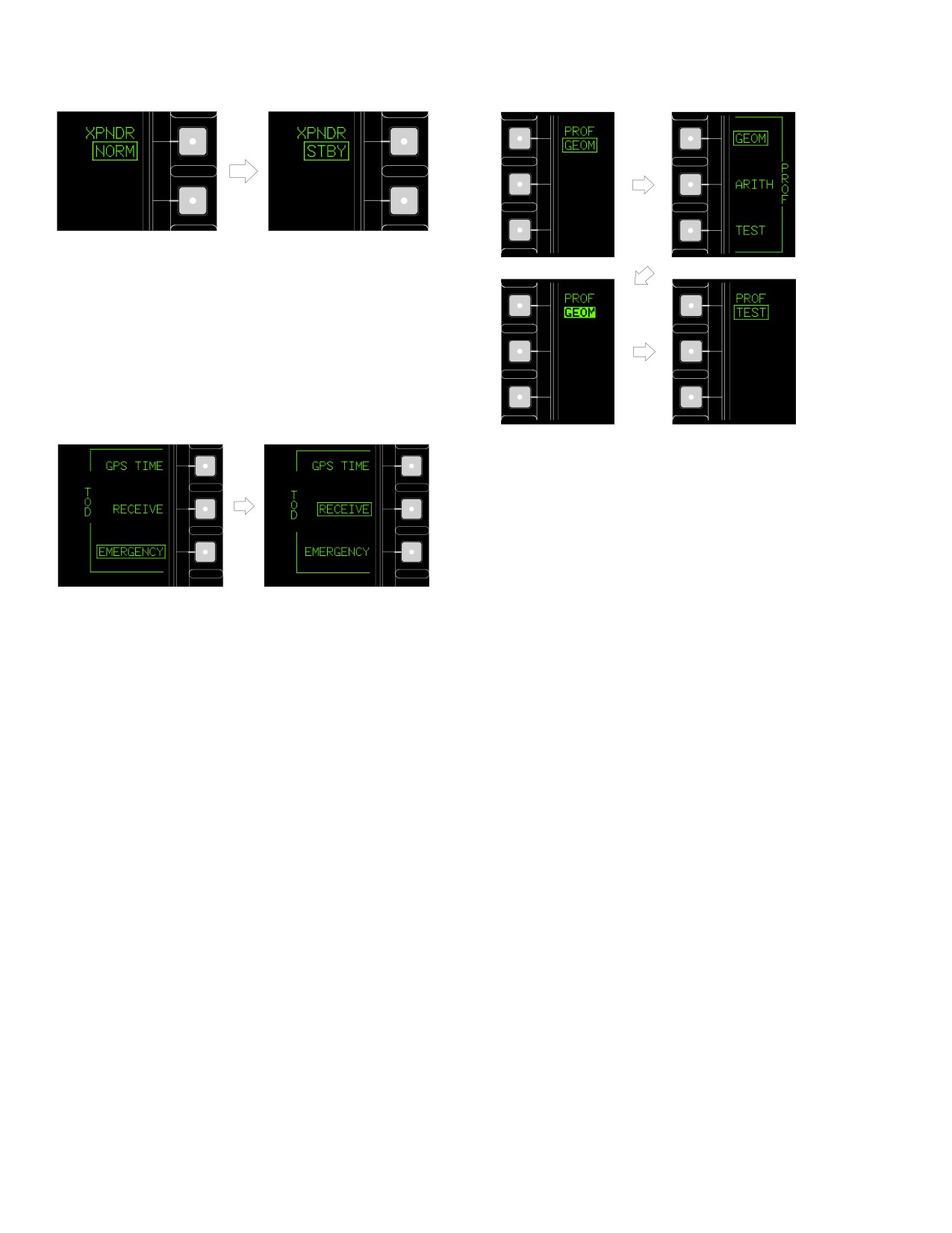
TM 1-1520-251-10
XPNDR Set to NORM
XPNDR Set to STBY
LBA1942
Figure 2-15. Two State Pushbutton Operation
(3) Grouped and Multi-State Option Pushbut-
tons. Grouped and Multi-state option pushbuttons (figs
2-16 and 2-17 ) are used to select the desired state of a
system or operating mode when there are three or more
options.
Current state is GEOM,
but changing.
LBA1944
Figure 2-17. Multi-State Pushbutton Operation
EMERGENCY Selected
RECEIVE Selected
LBA1943
(4) Data Entry Pushbuttons. Data entry pushbut-
Figure 2-16. Grouped Option Pushbutton
tons (fig 2-18) are used to enter alphanumeric and special
Operation
character data entry using the Keyboard Unit (KU).
Use or disclosure of this information is subject to the restriction(s) on the title page of this document.
2-16
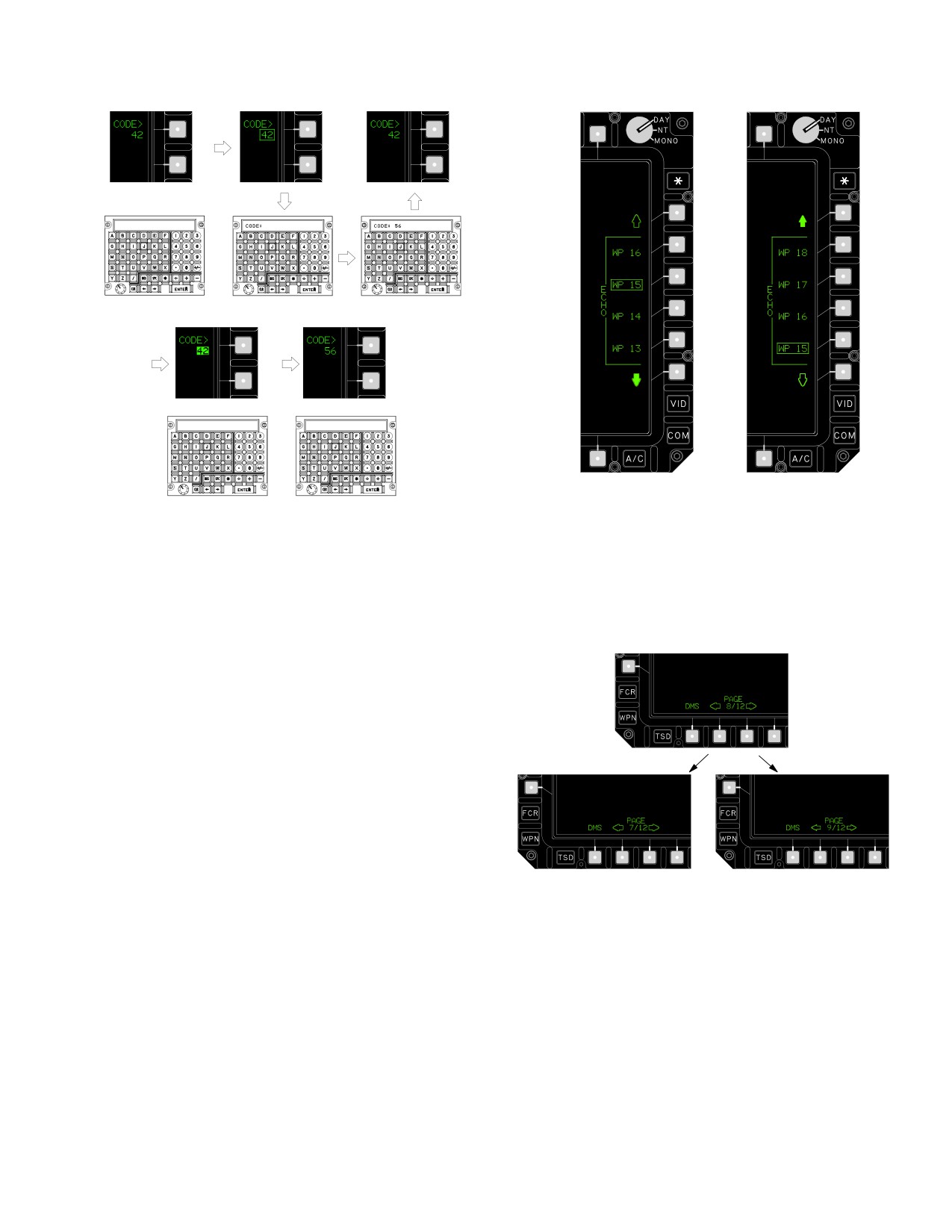
TM 1-1520-251-10
DATA BEGINS AND
PASSES VALIDITY CHECK
Lower part of list
Upper part of list
KU IS AVAILABLE
(below WP 13) is
(above WP 18)
FOR OTHER TASKS
LBA1945A
being brought
is being brought
into view.
into view.
LBA1946
Figure 2-18. Data Entry Pushbutton Operation
Figure 2-19. Search Pushbutton Operation
(5) Search Pushbuttons. Search pushbuttons
(6) Paging List Pushbuttons. Paging list push-
(fig 2-19) are used to scroll through lists of buttons or to
buttons (fig 2-20) are used to select previous (left) and
move graphics up or down.
next (right) pages.
Previous Page
Next Page
LBA1947
Figure 2-20. Paging List Pushbutton Operation
Use or disclosure of this information is subject to the restriction(s) on the title page of this document.
2-17
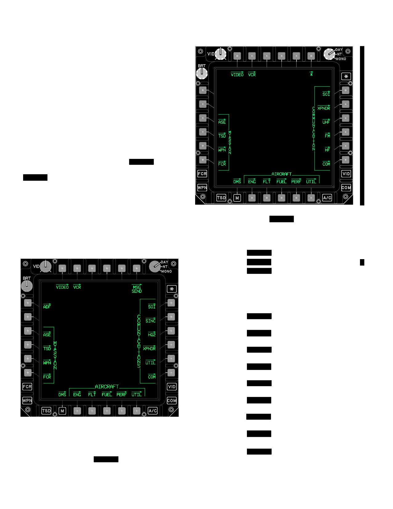
TM 1-1520-251-10
2.21 MPD PAGES
MPD pages are selectable by actioning variable action
bezel page buttons, fixed action buttons (FCR, WPN,
TSD, A/C, COM, or VID), or the Menu (M) button. Most
MPD formats and their component controls operate inde-
pendently. The same page may be presented on more
than one MPD in the same crew station, or on one MPD in
each crew station.
2.21.1
Subsystem Organization and the Menu
Page. All aircraft top-level pages can be accessed via
the MPD through the Menu page (figs [
BLK 1
2-21] and
[
BLK 2
2-21A] ). The Menu page is accessed by select-
ing the M bezel button on the MPD. The top level format
presented on that MPD is the format selected by the Menu
page or subsystem button (FCR, WPN, TSD, A/C, COM,
or VID). The top level format label is presented over the M
button. Double actioning the menu button will call up the
Figure
2-21A.
[
BLK 2
Menu Page]
DMS page from any other page (except the Menu page).
• T1
VIDEO page button
• T2
VCR page button
• T6
[
BLK 1
MSG SEND page button]
• T6
[
BLK 2
* page button]
• L1
[
BLK 1
ADF page button]
• L3
MISSION ASE page button
• L4
MISSION TSD page button
• L5
MISSION WPN page button
• L6
MISSION FCR page button
• R1
[
BLK 1
COMMUNICATIONS SOI
page button]
• R1
[
BLK 2
COMMUNICATION SOI
page button]
• R2
[
BLK 1
COMMUNICATIONS SINC
page button
• R2
[
BLK 2
COMMUNICATION XPNDR
page button]
• R3
[
BLK 1
COMMUNICATIONS
HQ1/HQ2 page button]
• R3
[
BLK 2
COMMUNICATION UHF
page button]
• R4
[
BLK 1
COMMUNICATIONS XPNDR
LBA5197
page button]
• R4
[
BLK 2
COMMUNICATION FM
page button]
• R5
[
BLK 1
COMMUNICATION UTIL
Figure
2-21.
[
BLK 1
Menu Page]
page button]
Use or disclosure of this information is subject to the restriction(s) on the title page of this document.
2-18
Change 3
TM 1-1520-251-10
• R5
[
BLK 2
COMMUNICATION HF
i.
[
BLK 2
COMMUNICATION FM Page Button.
page button]
The COMMUNICATION FM page button displays the FM
page.]
• R6
[
BLK 1
COMMUNICATIONS COM
page button]
j.
[
BLK 2
COMMUNICATION HF Page Button.
The COMMUNICATION HF page button displays the HF
• R6
[
BLK 2
COMMUNICATION COM
page.]
page button]
k.
[
BLK 1
COMMUNICATION UTIL button. The
• B1
DMS page button
UTIL button (para 3.45) provides access to the commu-
• B2
AIRCRAFT ENG page button
nications equipment Utility format.]
• B3
AIRCRAFT FLT page button
l. COMMUNICATION(S) COM button. The COM
• B4
AIRCRAFT FUEL page button
button (para 3.21) provides access to presets and tuning.
• B5
AIRCRAFT PERF page button
m. DMS button. The DMS button (para 2.128) pro-
vides access to the Data Management formats including
• B6
AIRCRAFT UTIL page button
warnings, cautions, advisories, faults, exceedences,
The top-level pages for the Fire Control Radar FCR,
built - in tests, and software versions.
Weapons WPN, Tactical Situation Display TSD, Aircraft
n. AIRCRAFT ENG button. The ENG button (Para
A/C, Communications COM, and Video VID controls can
2.110.1.a) provides access to engine instruments.
also be accessed directly through their respective subsys-
tem buttons. The DMS top level page is accessible from
o. AIRCRAFT FLT button. The FLT button (para
any other page by double action of the Menu button.
2.110.1.b) provides access to flight instruments.
p. AIRCRAFT FUEL button. The FUEL button (para
a. VIDEO button. The VIDEO button (para 4.54.1) pro-
2.110.1.c) provides access to fuel system controls.
vides access to real-time display of sensor video controls.
q. AIRCRAFT PERF button. The PERF button (para
b. VCR button. The VCR button (para 4.54) provides
2.110.1.d)) provides access to performance information
access to Video Cassette Recorder (VCR) controls, in-
and controls.
cluding on-board recording and tape playback.
r. AIRCRAFT UTIL button. The UTIL button (para
c.
[
BLK 1
MSG SEND button. The MSG SEND
2.110.1.e) provides access to the aircraft subsystem utility
button (para 3.21.1) provides access to sending mission
controls, including the cockpit environmental control sys-
files controls.]
tem, icing controls, and flight controls.
c1.
[
BLK 2
Asterisk (*) button. The * button (para
s.
[
BLK 1
ADF button. The ADF button (para
2.21.3A) provides access setup to the * fixed action but-
3.65) provides access to control moding of the Automatic
ton.]
Direction Finder system, and provides the symbology
necessary to perform ADF navigation.]
d. COMMUNICATION(S) SOI button. The SOI but-
ton (para 3.21.2) provides access to Signal Operating
t. MISSION ASE button. The ASE button (para
Instructions management.
4.89) provides access to Aircraft Survivability Equipment
(radar warning receiver, RFI, chaff, etc.) and display of
e.
[
BLK 1
COMMUNICATIONS SINC button. The
any detected threats.
SINC button (para 3.35.2) provides access to SINCGARS
(FM anti-jamming).]
u. MISSION TSD button. The TSD button (para 3.62)
provides access to the Tactical Situation Display navigation
f.
[
BLK 1
COMMUNICATION HQ1 or HQ2 button.
route, hazards, threat, and target coordinates, display of
The HQ1 button (para 3.38 ) provides access to Have Quick
boundary lines, phase lines, and engagement areas as well
1; the HQ2 button (para 3.41) provides access to Have Quick
as sensor footprint area.
2 (UHF anti-jamming). The HQ1 button is presented when
v. MISSION WPN button. The WPN button (para 4.6)
Have Quick 1 equipment is installed; the HQ2 button is pres-
provides access to weapons mode, weapons status (loads,
ented when Have Quick 2 equipment is installed.]
coding, tracking, faults), arm/safe status, sight and acquisition
g. COMMUNICATION(S) XPNDR button. The XPNDR
source moding, LRFD and LST coding, IHADSS grayscale,
button (para 3.44) provides access to transponder controls.
boresight controls, and chaff dispense status.
h.
[
BLK 2
COMMUNICATION UHF Page Button.
w. MISSION FCR button
. The FCR button (para
The COMMUNICATION UHF page button displays the
4.35) provides access to Fire Control Radar targeting and
UHF page.]
radar scan moding controls.
Use or disclosure of this information is subject to the restriction(s) on the title page of this document.
Change 3
2-19
TM 1-1520-251-10
2.21.2 Automatic Paging (Autopaging) of MPD For-
b. Engine Start. If the pilot power quadrant ENG
mats. The ENG page is automatically presented to the
START switch is pressed, the ENG Ground page will be
crew in response to all aircraft warning messages that have
autopaged in the pilots station only. Advancing both power
voice message capability. ASE information is automatically
levers to FLY causes the ENG page to change from
presented to the crew in response to detection of Radar La-
Ground format to Air format.
ser Warning Receiver (RLWR) or Radar Frequency Inter-
c. Sight Select FCR
. Selecting the sight select
ferometer (RFI) threats. ASE autopage thresholds may be
switch to FCR establishes control of the FCR to that crew
set in accordance with paragraphs 4.89.6 through 4.89.8.
station in the mode/format last selected at the FCR mode
switch (from either crew station). If the FCR page is not
When ENG is autopaged, it is presented on the left MPD un-
currently displayed on either MPD or the ORT HOD/HDD
less the right MPD already presents the ENG page, or unless
(CPG station), it is automatically called up on the left MPD
the left MPD presents FLT page. In the latter cases, the right
(in that crew station). All controls are available. Sight
MPD presents the ENG page. The CPG can suppress ENG
selection of the FCR between the crew stations is based
autopaging in his crew station using the DMS AUTOPAGE
on last-to-select logic.
button located on the DMS UTIL page.
d. Instant FLT Page Access/Return. Pressing the
center position (Z - axis) of the Symbol Select Switch on
When ASE information is autopaged, the system will either,
the Cycic Control Grip in either crewstation will autopage
update a currently displayed ASE page, provide ASE in-
switch that crewmember’s FLT Page to the left MPD.
formation on a currently displayed TSD Page, or autopage
When the switch is pressed, the system will either:
the TSD with ASE information shown. When autopaged, the
TSD page is presented on the right or left MPD unless that
• Have no effect if the FLT instruments page is
MPD presents the FLT instruments page, and there is a
currently displayed on the left MPD.
warning and the MPD presents the ENG page. Either crew-
• Move the FLT page to the left MPD if not currently
member can disable or alter the level of RFI or RLWR threat
displayed on either MPD.
detected which causes an ASE information autopage through
the AUTOPAGE grouped option button located on the ASE
• If the FLT page is currently displayed on the right
page or by multi-state option button on the TSD UTIL page.
MPD, it will be moved to the left MPD and the format
Threat detection threshold selections to trigger autopaging
on the left MPD will be moved to the right MPD.
are Search, Acquisition, and Track. See paragraph 4.89.
Subsequent switch selection will toggle the left MPD between
the Flight Page format and the previous page selection. The
If the current page on the MPD was displaying a video un-
return function will remain in effect until a page change oc-
derlay when an autopage to the TSD page occurred, the
curs as a result of entry into single DP, autopaging, switch
TSD page will be changed to show the stick map with the
paging, subsystem button selection, page button selection, or
video underlay. Otherwise, the TSD page will be displayed
ten minutes elapses since last return selection.
with the map underlay that was last viewed on one of the
TSD pages.
2.21.3A [
BLK 2
Asterisk (*) Page. The * page (fig
2-21B) allows either crewmember to store frequently used
2.21.3 Switch Paging of MPD Formats. The following
favorite pages in one or all of the three available queue
physical switch actions cause an autopage to the MPD
positions 1-3. Each MPD is capable of storing three
without bezel button selection:
pages for a total of six pages per crewstation. Selecting
the asterisk (*) button will cycle through the stored pages
a. Emergency Hydraulic (EMER HYD) Switch. If
in the numerical order indicated in the page store status
the EMER HYD switch on the EMERGENCY panel is
window on the respective MPD. An arrow in the page
pressed, the ENG page will be autopaged.
store status window indicates the current selected page.]
Use or disclosure of this information is subject to the restriction(s) on the title page of this document.
2-20
Change 3
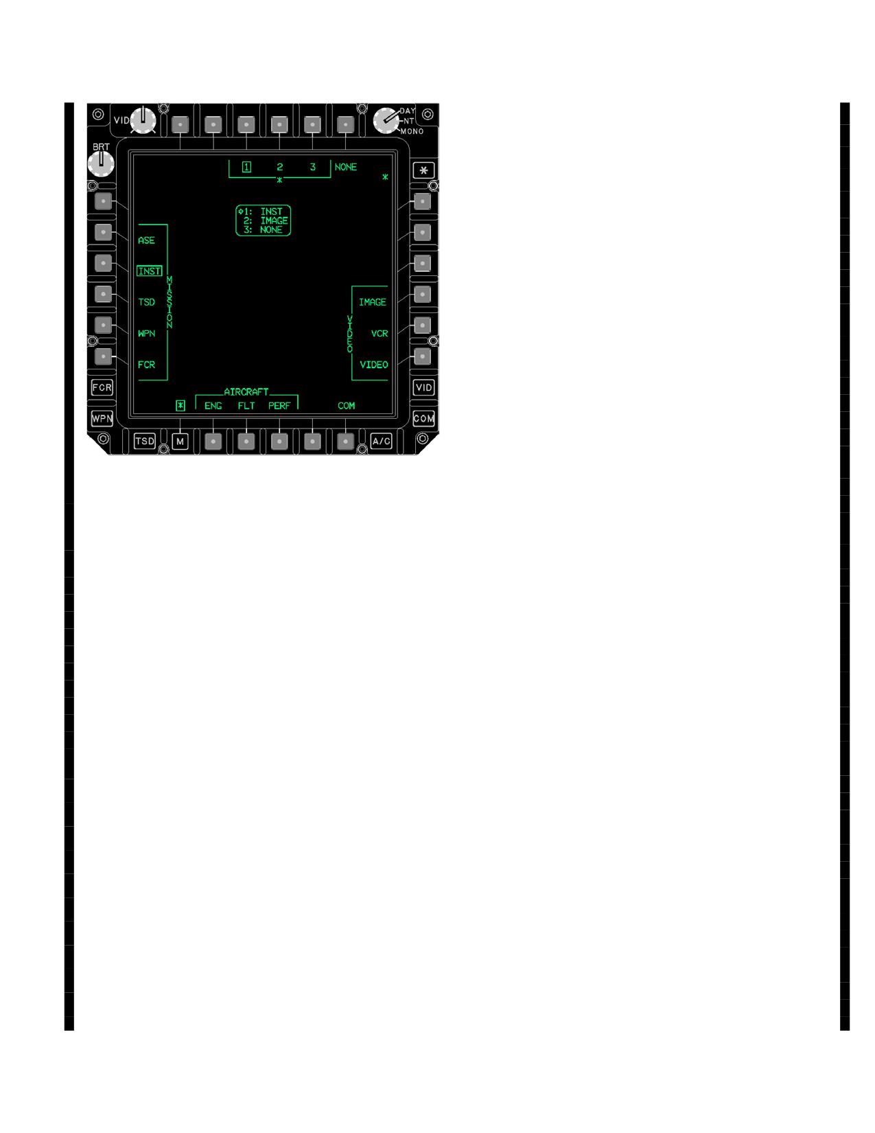
TM 1-1520-251-10
• B5
COM Page store button
• *
ASTERISK page cycle button
• R3
IMAGE Page store button
• R4
VCR Page store button
• R5
VIDEO Page store button
a. Queue 1 - 3 Buttons. Selecting any of the Queue
buttons determines the location for a page to be stored.
The default sequence for storing is 1 - 2 - 3 based on the
first available empty location. An empty location is indi-
cated with NONE shown in a queue position 1 - 3 in the
page store status window.
NOTE
Selecting any of the MISSION, AIRCRAFT,
COM or VIDEO pages from the ASTERISK
page will store that page in the currently
boxed queue position 1-3 regardless of
whether a position indicates NONE or a
page is already stored.
LBA5284
b. NONE Button Selection of the NONE button
erases the page stored in the currently boxed Queue posi-
Figure
2-21B. Asterisk (*) Page
tion 1 - 3.
NOTE
NOTE
When NONE is stored in a Queue 1 - 3, that
When at least one page has been stored the
position will be skipped in the page cycle se-
asterisk (*) label will appear next to the as-
quence.
terisk button. This indicates a memory page
is available to view by selecting the asterisk
c. ASE Page Store Button. Selection of the ASE
button. Crewmembers may also select
Page button stores the ASE page in the currently boxed
memory pages via the cursor controller on
Queue position 1 - 3.
either collective or the left hand grip by posi-
tioning the cursor over the (*). The asterisk
d. INST Page Store Button. Selection of the INST
will become bold and selecting the z - axis/
Page button stores the INST page in the currently boxed
cursor enter will cycle through the stored
Queue position 1 - 3.
pages in queue order.
• T3
Queue 1 button
e. TSD Page Store Button. Selection of the TSD Pa-
ge button stores the TSD page in the currently boxed
• T4
Queue 2 button
Queue position 1 - 3.
• T5
Queue 3 button
f. WPN Page Store Button. Selection of the WPN
• T6
NONE button
Page button stores the WPN page in the currently boxed
• L1
ASE Page store button
Queue position 1 - 3.
• L2
INST Page store button
g. FCR Page Store Button. Selection of the FCR Pa-
• L3
TSD Page store button
ge button stores the FCR page in the currently boxed
• L4
WPN Page store button
Queue position 1 - 3.
• B1
ENG Page store button
h. ENG Page Store Button. Selection of the ENG
• B2
FLT Page store button
Page button stores the ENG page in the currently boxed
• B3
PERF Page store button
Queue position 1 - 3.
Use or disclosure of this information is subject to the restriction(s) on the title page of this document.
Change 3
2-20.1
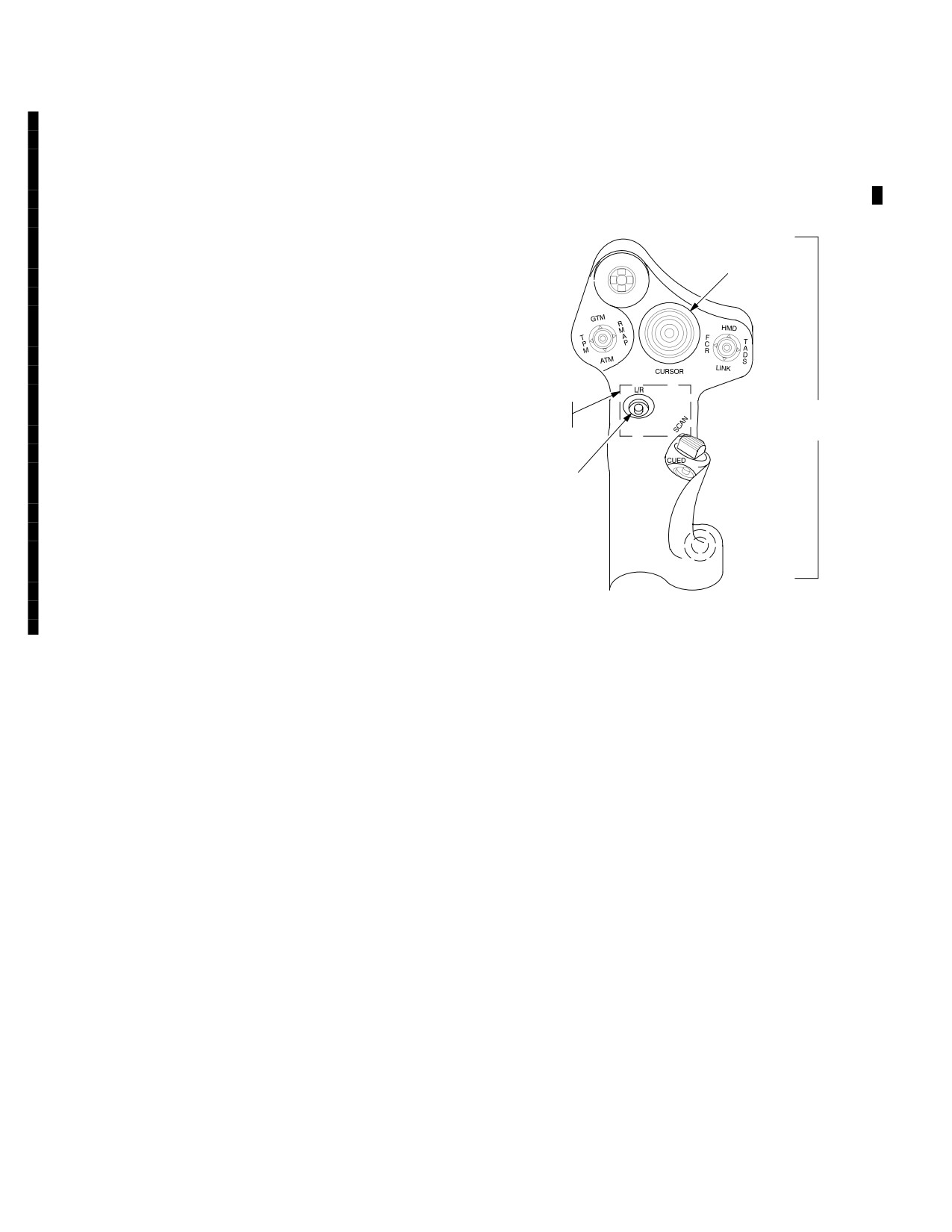
TM 1-1520-251-10
i. FLT Page Store Button. Selection of the FLT Pa-
2.21.4 MPD Cursor Controller/Enter. Both crewmem-
ge button stores the FLT page in the currently boxed
bers have the capability to select options on the MPD through
Queue position 1 - 3.
the use of cursor controls mounted on the collective Mission
Control Grip
(fig
2-22) and the Optical Relay Tube
(ORT)/TADS Electronic Display and Control (TEDAC) hand-
i. PERF Page Store Button. Selection of the PERF
grips (fig 2-23).
Page button stores the PERF page in the currently boxed
Queue position 1 - 3.
CURSOR
Z
CONTROLLER/ENTER
j. COM Page Store Button. Selection of the COM
N
W
Page button stores the COM page in the currently boxed
M
Queue position 1 - 3.
k. ASTERISK Page Cycle Button. Selection of the
ASTERISK button cycles through the stored pages in
Queue position order 1 - 3.
CURSOR ENTER
MISSION
(FAR SIDE)
CONTROL
l. IMAGE Page Store Button. Selection of the
GRIP
IMAGE Page button stores the IMAGE page in the cur-
rently boxed Queue position 1 - 3.
CURSOR
DISPLAY
m. VCR Page Store Button. Selection of the VCR Pa-
SELECT
ge button stores the VCR page in the currently boxed
Queue position 1 - 3.
n. VIDEO Page Store Button. Selection of the VID-
LBA0462
EO page button stores the VIDEO page in the currently
boxed Queue position 1 - 3.
Figure 2-22. Mission Control Grip Cursor Controls
Use or disclosure of this information is subject to the restriction(s) on the title page of this document.
2-20.2
Change 3
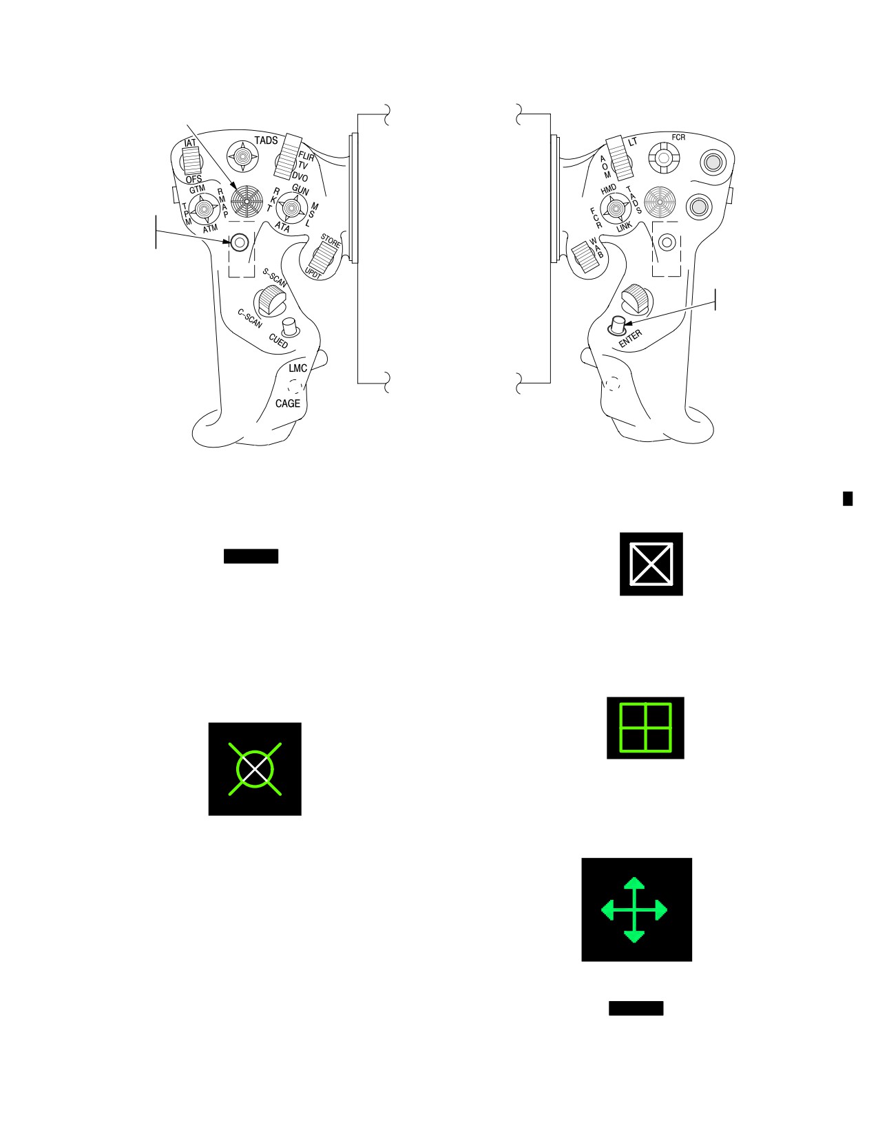
TM 1-1520-251-10
CURSOR CONTROLLER/ENTER
Z
Z
CSCOPE
N
W
M
W
M
N
VIDEO
SLAVE
RCD
FLIR
PLRT
CURSOR
CURSOR
MAN TRK
DISPLAY
SELECT
LASER
L/R
ZOOM
TRIGGER
WEAPONS
TRIGGER
CURSOR
ENTER
HDD
ADV
LBA0461
Figure 2-23. Handgrips
Control of the pilot and CPG’s MPD cursor symbols (figs
2-24, 2-25, 2-26 and [
BLK 2
2-26A] ) in each crew sta-
tion is independent of the other crew station. Bezel button
inputs override simultaneous cursor entered inputs. Cen-
tral crosshairs are presented when in an operating mode
LBA1948
which allows selection of individual symbols. When pick-
ing a symbol, the object to be selected is shown over a
Figure 2-25. MPD Cursor Symbol FCR Zoom
black circle.
Operation
LBA1949
Figure 2-26. MPD Cursor Symbol Target Reference
LBA0467A
Point
Figure 2-24. MPD Cursor Symbol
During FCR Zoom and TSD page target reference point
LBA5196
creation, the cursor symbol graphic changes to a size en-
compassing the area to be zoomed or to be the target ref-
Figure 2-26A.
[
BLK 2
MPD Cursor Panning
erence point. FCR Zoom cursor is WHITE in color.
Operation]
Use or disclosure of this information is subject to the restriction(s) on the title page of this document.
Change 3
2-21
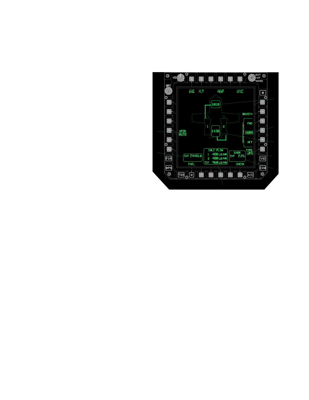
TM 1-1520-251-10
2.21.5 MPD Cursor Operation. The cursor is posi-
2.22.2 MPD Status Indications and Readouts. Infor-
tioned on the MPD by providing a force input in the direc-
mation which is provided by a system, such as status in-
tion of desired movement. Cursor speed increases with
dications or digital readouts, are contained within a status
increasing force applied. The cursor is positioned to
window with rounded corners (fig 2-27). Crewmember se-
another display by moving it to the adjacent edge of the
lected options are indicated by a box.
MPD, and then double bumping it over to the next ORT or
MPD display. The cursor can be moved to the center of
the other MPD by selecting the collective Mission Control
Grip or ORT LHG CURSOR Display Select button. Items
or buttons can be selected by pressing the center detent
of the cursor force controller, by pressing the cursor enter
1
on the collective mission grip, or by selecting the ENTER
pushbutton on the ORT RHG. The cursor is stowed in the
lower left corner of the display 3 minutes after the last use.
If on the TSD or FCR page, and in a valid selection area,
2
the cursor will remain in that valid selection indefinitely. If
8
moved from the valid selection area, the cursor will stow
after 3 minutes. The cursor is automatically positioned to
3
the FCR page’s NTS button when a crewmember who has
7
the FCR as his selected sight initiates an FCR scan or se-
4
lects a new next-to-shoot symbol using the cursor. See
paragraph 2.23 for single DP cursor operations.
5
2.22 GENERAL STATES OF MPD OPERATION
6
Crewmembers are provided consistent display feedback
LBA2578B
to indicate the current aircraft states. In general, informa-
tion is displayed by exception. If it is not relevant to the
Figure
2-27. MPD Status Indicators and Readouts
current task or conditions, it will not be presented. For ex-
ample, engine instruments will not routinely be presented
1.
FWD FUEL CELL QTY STATUS
constantly on the MPD after engine startup. However, the
system will provide the ENG page automatically if an
2.
FUEL CROSSFEED OPTION
emergency condition occurs. Similarly, controls for radios
which are currently not installed are not presented on the
3.
AFT FUEL CELL QTY STATUS
MPDs.
4.
FUEL TYPE OPTION
2.22.1
MPD Color Application. Seven colors are
5.
TIME REMAINING W/CURRENT FUEL STA-
used to indicate the following conditions:
TUS
• Green: Normal (default), advisory conditions
6.
CALCULATED FUEL FLOW STATUS
• Red: Warnings, Enemy Threats
7.
TOTAL REMAINING INTERNAL FUEL QTY
• Yellow: Cautions, Hazards
STATUS
• White: Attention
8.
FUEL TRANSFER OPTION
• Cyan: Friendlies, sky of attitude indicator
2.22.3 Bezel Button/Label Not Selectable. If a button
is not selectable in the current operating mode, and does
• Brown: Ground of attitude indicator
not contain relevant information, it is not displayed. If a
• Partial Intensity of any of these colors, to de - em-
button is not selectable in the current operating mode and
phasize normal conditions. Partial green may
does contain relevant information, it is displayed with a
appear blue - green. Partial yellow may appear
partial intensity barrier, separating it from the adjacent be-
brown or orange.
zel button (fig 2-28).
Use or disclosure of this information is subject to the restriction(s) on the title page of this document.
2-22
Change 2
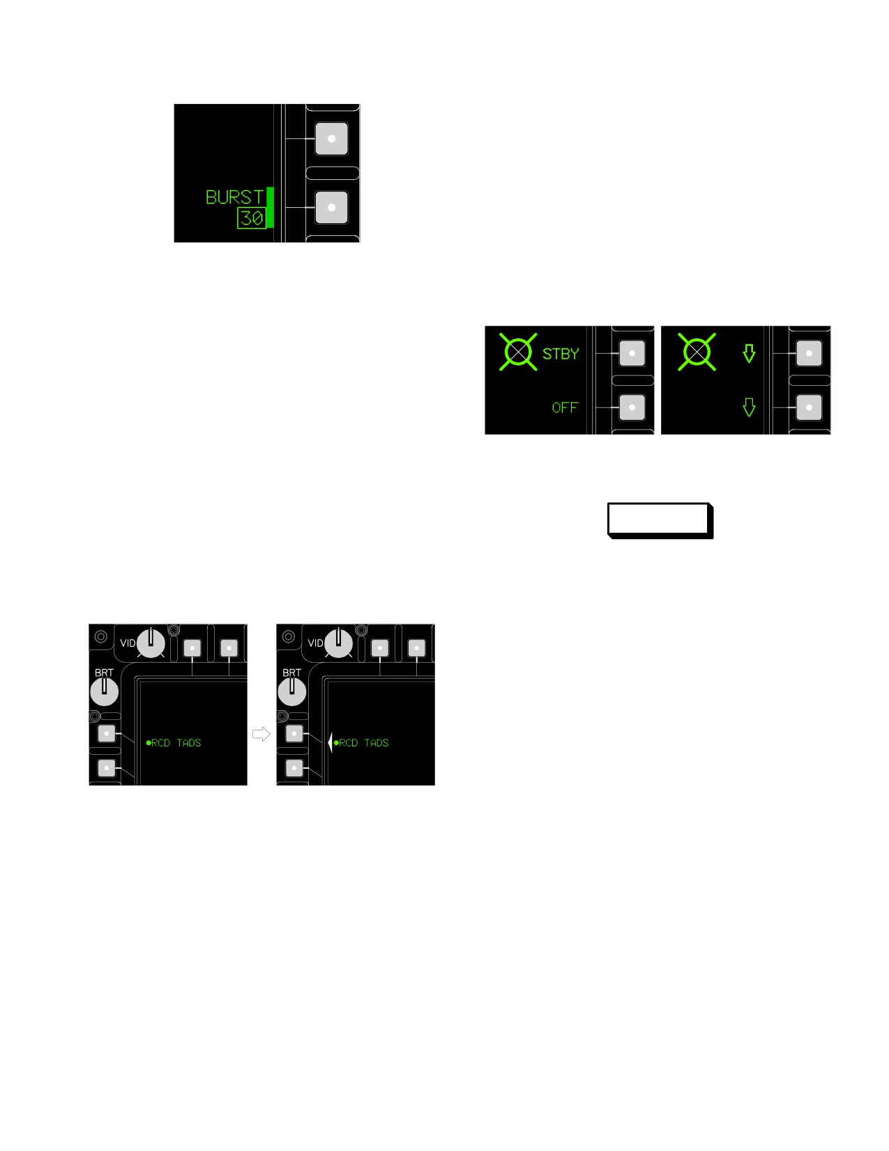
TM 1-1520-251-10
data field. If this is a result of a system error, or is a non -
standard condition, this question mark will be WHITE in
color.
2.22.7 Bold Font / Characters. Button labels show
bold intensity when the cursor is close enough to the sym-
bol to choose it (fig 2-30). Upon cursor selection, the
bolded item will be chosen. Bold fonts are also applied to
any characters shown in inverse video, and any charac-
LBA1951
ters which are shown RED or YELLOW in color. Note:
when operating in MONO mode, characters which would
be shown RED or YELLOW during NIGHT mode opera-
Figure 2-28. Not Selectable Bezel Edge Barrier
tions continue to be shown in bold font.
2.22.4 Operation In Progress (OIP). The current state
of buttons are shown in inverse video while their state is
changing, or an operation is in progress. The new state is
shown at the completion of the process in normal video.
Buttons cannot be selected while they are OIP. OIP in-
verse video states are shown on all button presentations
within the aircraft that they affect. Figure 2-13 shows an
Text Bolding
Symbol Bolding
LBA1953
example of the inverse video cue used for an operation in
progress.
Figure 2-30. Bold Character Presentation
2.22.5 Command Failed. If an operator command was
not implemented by the system, the button selected is
WARNING
shown with a white triangle (fig 2-29 ) between the button
and text label, pointing to the button to be selected for a
While in single display processor opera-
retry. Command fail triangles are shown on all the air-
tion, the format presented (including
craft’s affected buttons.
weapons configuration information)
could belong to the opposite crew mem-
ber.
2.23 MPD PAGES DURING SINGLE DISPLAY
PROCESSOR (DP) OPERATION
During single DP operation, the original four MPD pages
within the aircraft are reduced to two, with the left MPDs of
both crew stations duplicating each other, and the right
MPDs of both crew stations duplicating the other. Once a
display processor has been lost, it will not be recognized
as functioning again for a minimum of 10 seconds. Upon
L1 Selected
LBA1952
determining a DP is operational again, the MPDs will re-
tain the same formats as presented during single DP
mode, but in normal DP appearance and functionality. As
Figure 2-29. Command Failed Bezel Edge Triangle
a result of the page changes resulting from the failure, any
ongoing crew operations at the time of the transition will
2.22.6 Data Field Presentation of Invalid or Missing
be aborted. KU scratchpad data will be lost. During single
Data. Data fields, located in a data entry button or the
DP operation, the CPG’s cursor symbol graphic changes
center area of the page, display the value sent to them,
so it can be easily seen and separated from the pilot cur-
whether that value is within the specified validity range or
sor, even if they are both in the home position or format
not. If the DTC loaded data is invalid (a checksum error
center (fig 2-31). The pilots cursor does not change. Both
was found), the data is considered to be missing. If data is
cursors are visible in both crewstations.
missing for any reason a question mark is presented in the
Use or disclosure of this information is subject to the restriction(s) on the title page of this document.
2-23
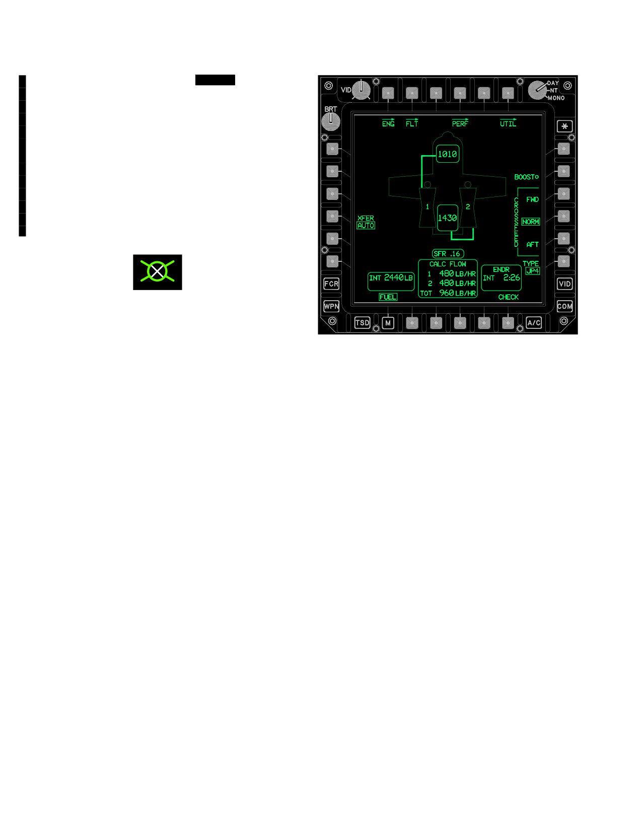
TM 1-1520-251-10
2.23.1 MPD Stale Operations.
[
BLK 2
During MPD
Stale operations (single DP operations only), graphics
and video on the affected display will not be current and
the MPD bezel buttons may not respond to commands.
Once an MPD Stale condition is recognized, the crew
should disregard the information on the stale MPD and
use the functional display. While in single DP with a LEFT
or RIGHT MPD STALE message, display information criti-
cal for maintaining aircraft control should be placed on the
“non - stale” MPD. The aircrew should perform operations
in accordance with SINGLE DP operations. With the
IHADSS/ORT STALE message active the crew should fol-
low procedures as in total HDU Failure (para 9.26.2.b).]
LBA1954
Figure 2-31. CPG MPD Cursor Symbol (Single DP
LBA5192
Operation)
Figure 2-32. Single DP Failure (Fuel)
2.23.2 MPD Format Selection. Following a failure of
one of the two DPs, the remaining processor acknowl-
2.23.4 MPD Format Control. Formats presenting pilot
edges the failure and notes the formats originally dis-
information can be brought to the left or right set of dis-
played in each of the four MPDs. A priority scheme deter-
plays by selecting them from the pilot station. Formats
mines the presentation of formats. In general, FLT page is
presenting CPG information can be brought to the left or
the highest priority format, followed by the ENG page in
right set of displays by selecting them from the CPG’s sta-
the presence of an active warning, and finally the TSD
tion. The ownership of the format is assigned to the crew-
page. The system identifies whether one of these top
member selecting the page (last format select logic). VID
three priority formats are present, and retains the highest
knob and SHARP operations also follow a last - select log-
priority page in each crewstation. The FLT page is consid-
ic. If either left display’s DAY/NIGHT/MONO knob is set to
ered to be a crucial display because it must be assumed
MONO, then the left displays of both crewstations will
that if a crewmember has this format shown, he may be
present only green symbology and video. Similarly, if ei-
relying upon it for flight. Whenever possible, the FLT,
ther right display’s DAY/NIGHT/MONO knob is set to
ENG, and TSD pages are not switched from left to right.
MONO, then the right displays of both crewstations will
present only green symbology and video. Otherwise, full
If there are no priority pages presented, pages are re-
color symbology and white or green video will be avail-
tained based on their location: pilot retains his left format,
able. Backlight brightness (BRT range) will be in accor-
CPG retains his right format. If a retained page presents
dance with that MPD’s DAY/NIGHT/MONO setting.
video underlay, then that video is also retained.
2.24 KEYBOARD UNIT (KU)
2.23.3 MPD Format Appearance. The MPD formats
present bold lines at the top and/or bottom of the format to
The KU (fig 2-33) is a multipurpose control through which
provide an indication of the single DP failure. Formats
the crew can enter alphanumeric and special character
presenting pilot information will present a WHITE bold line
data. The KU has an integrated light emitting diode (LED)
at the bottom of the page. Formats presenting CPG in-
scratchpad display to provide visual feedback for data
formation only will present a WHITE bold line at the top of
entry check, data entering prompts, calculator functions,
the page. Formats presenting information which applies to
and operator validation feedback. The KU communicates
the entire aircraft will have WHITE bold lines at the top
with the display processor via the MUX bus. The KU con-
and bottom of the page (fig 2-32). Control of the MPD is
sists of a scratchpad display, alphanumeric pushbuttons,
based on a “last format select” logic.
calculator function buttons, special function buttons, and a
Use or disclosure of this information is subject to the restriction(s) on the title page of this document.
2-24
Change 3
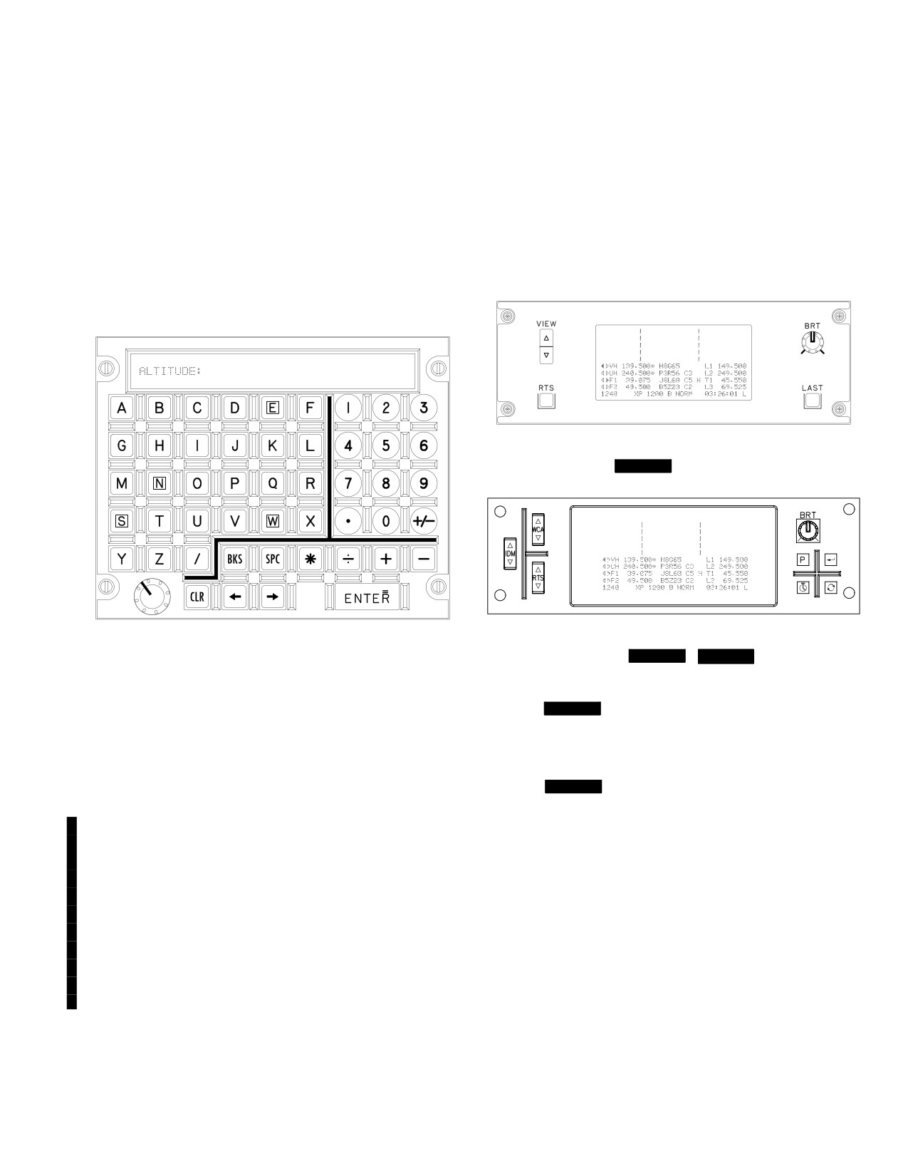
TM 1-1520-251-10
scratchpad display brightness control. When there is no
2.25 UP - FRONT DISPLAY (UFD)/ENHANCED
ongoing MPD data entry button operation, the KU can be
UP - FRONT DISPLAY (EUFD)
used as a notepad to enter data.
The UFDs/EUFDs (fig 2-34 and 2-35) provide uninterrupted
presentation of critical information under battery power and
2.24.1 Scratchpad Display. The KU scratchpad ac-
normal electrical power conditions. The first 5 lines of the ac-
cepts up to 44 characters, and can display up to 22 of
tive display is divided by vertical lines into warning, caution,
these characters at a time. If the scratchpad exceeds 22
and advisory areas (columnar, left to right). The next four
characters, the remaining text can be scrolled in and out
lines of the display present VHF, UHF, FM1 and FM2 radio
of the scratchpad area using the left or right arrows. The
status. The last line presents total fuel quantity, transponder
scratchpad also presents an up to 9 character prompt fol-
(XP) status, and local or Zulu time.
lowed by a colon. The scratchpad LEDs can be tested by
selecting the A and + keys simultaneously.
(Warnings)
(Cautions)
(Advisories)
LBA5194
Figure 2-34.
[
BLK 1
Up-Front Display (UFD)]
(Warnings)
(Cautions)
(Advisories)
LBA5195
LBA5193
Figure 2-35.
[
BLK 1
/
BLK 2
Enhanced
Figure 2-33. Keyboard Unit (KU)
Up-Front Display (EUFD)]
2.25.1 [
BLK 1
UFD. The UFD (fig 2-34) is a mono-
2.24.2 KU Lighting. The pushbutton brightness is con-
chrome, LED display. The display presents a test pattern to
trolled by the interior lights primary knob. Scratchpad bright-
check the LEDs when the RTS and LAST pushbuttons are
ness is controlled by the knob on the lower left corner of the
pressed simultaneously.]
unit. When the KU has not been in use for a minute, the dis-
play is not illuminated. Pressing any button or actioning a
2.25.2
[
BLK 1
UFD Controls. The UFD provides
data entry key will illuminate the keyboard display.
VIEW, RTS, LAST, and BRT controls.]
2.24.3 KU Operation. The KU becomes active in re-
a. VIEW Control. The UFD VIEW switch allows the list
sponse to MPD selection of a data entry button or if user in-
of caution and advisory information to be scrolled into view, if
put is required when a reauthentication request is issued by
either of the lists are more than five characters. If the caution
a Tactical Internet security officer. A short prompt and colon
list is more than five lines in length, the vertical line separating
are presented, indicating the anticipated data to be entered.
the list from the warnings is replaced by a triangle. If the list
No data is accepted by the system from the scratchpad until
has been scrolled off the top, the top line is replaced with a
ENTER is pressed. Upon selection of ENTER, the DP reads
triangle. Similarly, if the advisory list is more than five lines in
the scratchpad data and determines its validity. If it is valid,
length, the vertical line separating the list from the cautions is
this data is accepted and the scratchpad blanks. If it is invalid,
replaced by a triangle.
the scratchpad data will flash. The next operator keystroke
b. RTS Control. The RTS button selects the next
stops the flashing and allows the crew to edit the data.
radio as the transmitter. This button’s function is redun-
2.24.4 KU Keys. The KU provides alphanumeric, decimal,
dant to the RTS switch provided on the cyclic grip.
plus/minus, backspace, insert (space), left arrow, right arrow,
c. LAST Control. The LAST button tunes the se-
clear, multiply, divide, plus, minus, and enter/equals keys.
lected radio to the previous frequency.
Use or disclosure of this information is subject to the restriction(s) on the title page of this document.
Change 4
2-25

TM 1-1520-251-10
d. BRT Control. The BRT control varies the bright-
rocker switch can be momentarily pressed for single radio
ness of the UFD.
selection or continually pressed to scroll through the available
radios. Selection of the IDM rocker switch is circular such that
2.25.3
Enhanced Up-Front Display (EUFD). The
selection beyond the top or bottom of the list of available ra-
EUFD (fig 2-35) is a monochrome, LED display. The dis-
dios will cause the IDM tranmit symbol to be displayed at the
play presents a test pattern to check the LEDs when the
bottom or top of the list.
RTS (rocker switch - down) and swap buttons are pressed
c. RTS Control. The RTS rocker switch controls
simultaneously.
the selection of a radio for voice transmission. The left fac-
ing solid triangle is your current voice transmit radio. The
2.25.4 [
BLK 1
EUFD Controls. IDM, PRESET, EN-
right facing solid triangle is the other crew member’s voice
TER and STOPWATCH controls are currently non - func-
transmit radio. The RTS rocker switch allows cycling up or
tional selections. The EUFD does provide functional
down through the available radios to select a voice trans-
WCA, RTS and Swap controls.]
mit radio. The RTS rocker switch can be momentarily
a. View Control. The EUFD WCA rocker switch al-
pressed for single radio selection or continually pressed to
lows the display of warning, caution and advisory informa-
scroll through the available radios. Selection of the RTS
tion to be scrolled into view whenever a list contains more
rocker switch is circular such that selection beyond the top
than five lines of information. If any list is more than five
or bottom of the list of available radios will cause the RTS
lines in length, the vertical line separaring the warning and
transmit symbol to be displayed at the bottom or top of the
caution list and the line separating the caution and adviso-
list. NOTE: The RTS switch located on the cyclic grip only
ry list is augmented by double arrows. If a WCA list con-
allows cycling down through the available radios.
tains information not currently on the display, arrows are
d. Preset (P) Control. The Preset button opens or
presented indicating the direction the WCA rocker switch
closes the EUFD Preset Window on the EUFD display.
would need to be actioned to view this information.
The EUFD Preset Window is used to select one of ten pre-
b. RTS Control. The RTS switch selects the next
sets, in order to tune a single channel frequency into the
radio as the transmitter, regardless of whether the up or
current RTS radio.
down function is selected on the control. This switch is re-
e. Enter Control. The Enter button is used to initi-
dundant to RTS switch provided on the cyclic grip.
ate a tune of the current RTS radio, based on the preset
c. Swap Control. The Swap control
tunes the ra-
select arrow symbol displayed in the EUFD Preset Win-
dio to the previous frequency.
dow. Depressing the Enter button when the preset select
d. BRT Control. The BRT control varies the bright-
arrow symbol is displayed in the EUFD Preset Window will
ness of the EUFD.
close the EUFD Preset Window, regardless of whether or
2.25.5
[
BLK 2
EUFD Rocker Switch Push Con-
not the preset selected is valid (i.e. an invalid preset will
trols.
The EUFD rocker switch push controls are WCA,
not actually tune, but the EUFD Preset Window will close).
IDM, and RTS. The EUFD push button controls are Pre-
Depressing the Enter button when the preset select arrow
set, Enter, Stopwatch, and Swap. The EUFD control knob
symbol is not displayed in the EUFD Preset Window will
is BRT.]
not close the EUFD Preset Window, nor initiate a tune.
f. Stopwatch Control. The Stopwatch button
a. WCA Control. The WCA rocker switch controls
starts, stops, and resets the stopwatch function. The stop-
scrolling of the warning, caution, and advisory lists in the
watch timer field is displayed in the lower right portion of
upper portion of the EUFD. If there are more than seven
the EUFD display, above the clock field. Depressing the
warnings, cautions, or advisories to be displayed the verti-
Stopwatch button for the first time will start the stopwatch
cal lines separating the WCA lists will display a double ar-
timer. Depressing the Stopwatch button again will stop the
rowhead indicating the direction to scroll the WCA lists
stopwatch timer. To continue the stopwatch timer the
into view on the EUFD. The WCA rocker switch is also
Stopwatch button can be depressed again. To reset the
used inconjunction with the EUFD Preset Window to se-
stopwatch timer, the Stopwatch button needs to be held
lect one of ten presets for tuning the current RTS radio.
depressed for approximately 2 seconds. The stopwatch
b. IDM Control. The IDM rocker switch controls the
timer field is not displayed when reset. The stopwatch tim-
selection of a radio for IDM transmission. The inverse dia-
mond symbol is your current IDM transmit radio. The dia-
er function is independent in each crew station.
mond symbol is the other crew member’s IDM tranmit radio.
g. Swap Control. The Swap control
swaps the cur-
When both crew members have the same radio selected for
rent RTS radio, encryption, and IDM net configuration with
IDM transmit the symbols merge into a solid block symbol.
the standby radio, encryption, and IDM net configuration.
The IDM rocker switch allows cycling up or down through the
h. BRT Control. The BRT control varies the bright-
available radios to select an IDM transmit radio. The IDM
ness of the EUFD.
Use or disclosure of this information is subject to the restriction(s) on the title page of this document.
2-26
Change 2
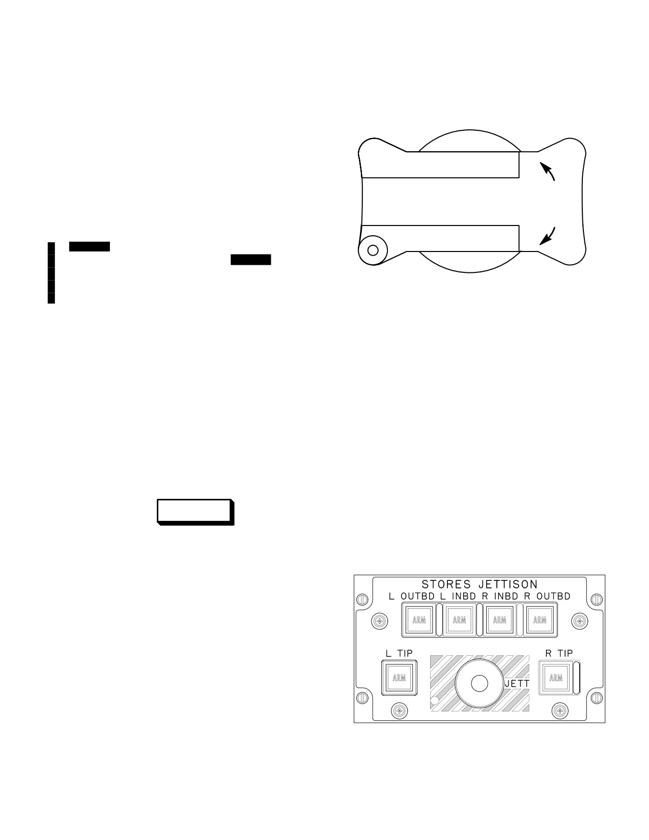
TM 1-1520-251-10
Section II. EMERGENCY EQUIPMENT
2.26 EMERGENCY EQUIPMENT
ÓÓÓ
SAFE
ÓÓÓÓÓÓÓÓÓÓÓ
ÓÓÓÓÓÓÓÓÓÓ
Emergency equipment on the helicopter consists of a
TURN
Canopy Jettison System, Stores Jettison System, porta-
CANOPY
90°
ble fire extinguisher, Engine and Auxiliary Power Unit
PUSH
JETTISON
(APU) Fire Detection/Extinguishing System, two first aid
ÓÓÓÓÓÓÓÓÓÓ
kits, and a sensitive data Master Zeroize Switch.
ÓÓÓÓÓÓÓÓÓÓ
[
BLK 1
Emergency equipment also includes Surviv-
ability Equipment - CBR Blower.] [
BLK 2
Emergency
ÓÓÓÓÓÓÓÓÓÓÓ
SAFE
equipment also includes Survivability Equipment - CBR
ÓÓ
LBA0022
Blower, Emergency Locator Transmitter and Underwater
Acoustic Beacon.]
Figure 2-36. CANOPY JETTISON Handle
2.28 STORES JETTISON SYSTEM
2.27 CANOPY JETTISON SYSTEM
NOTE
Only that crewstation arming the stores jetti-
The canopy jettison system is installed to provide a rapid
son panel can de-arm it. Once armed, either
emergency exit for the crewmembers. The transparent
crewstation can activate jettison.
portions of the four canopy side panels can be jettisoned
by means of a detonating cord installation. The system is
2.28.1 STORES JETTISON Panel. Pressing one or
controlled manually.
more of the alternate action pushbuttons on the STORES
JETTISON panel (fig 2-37) will illuminate the selected
pushbutton(s) to indicate that the stores jettison function
at selected stations is ARMed. Pressing an illuminated
pushbutton a second time will cause that pushbutton’s
WARNING
light to be extinguished, indicating that stores jettison at
that station is no longer ARMed. Pressing the recessed
JETT pushbutton will cause stores to be jettisoned from
all ARMed stations.
To prevent eye injury, pilot and CPG hel-
met visors should be down prior to
canopy jettison. Debris may be expelled
50 feet outward.
The CANOPY JETTISON handles (fig 2-36) are located in
the upper left area of the instrument panel in each crew
station. The handles incorporate a safety pin which is to
be removed before flight. Canopy jettison is accomplished
by turning the handle 90°, releasing, and pushing in
(TURN 90° PUSH). An external ground crew handle is lo-
cated under a quick release panel directly forward of the
LBA0080
forward crew compartment windshield. All four canopy
side panels are jettisoned by activating any of the three
jettison handles.
Figure 2-37. STORES JETTISON Panel
Use or disclosure of this information is subject to the restriction(s) on the title page of this document.
Change 2
2-27
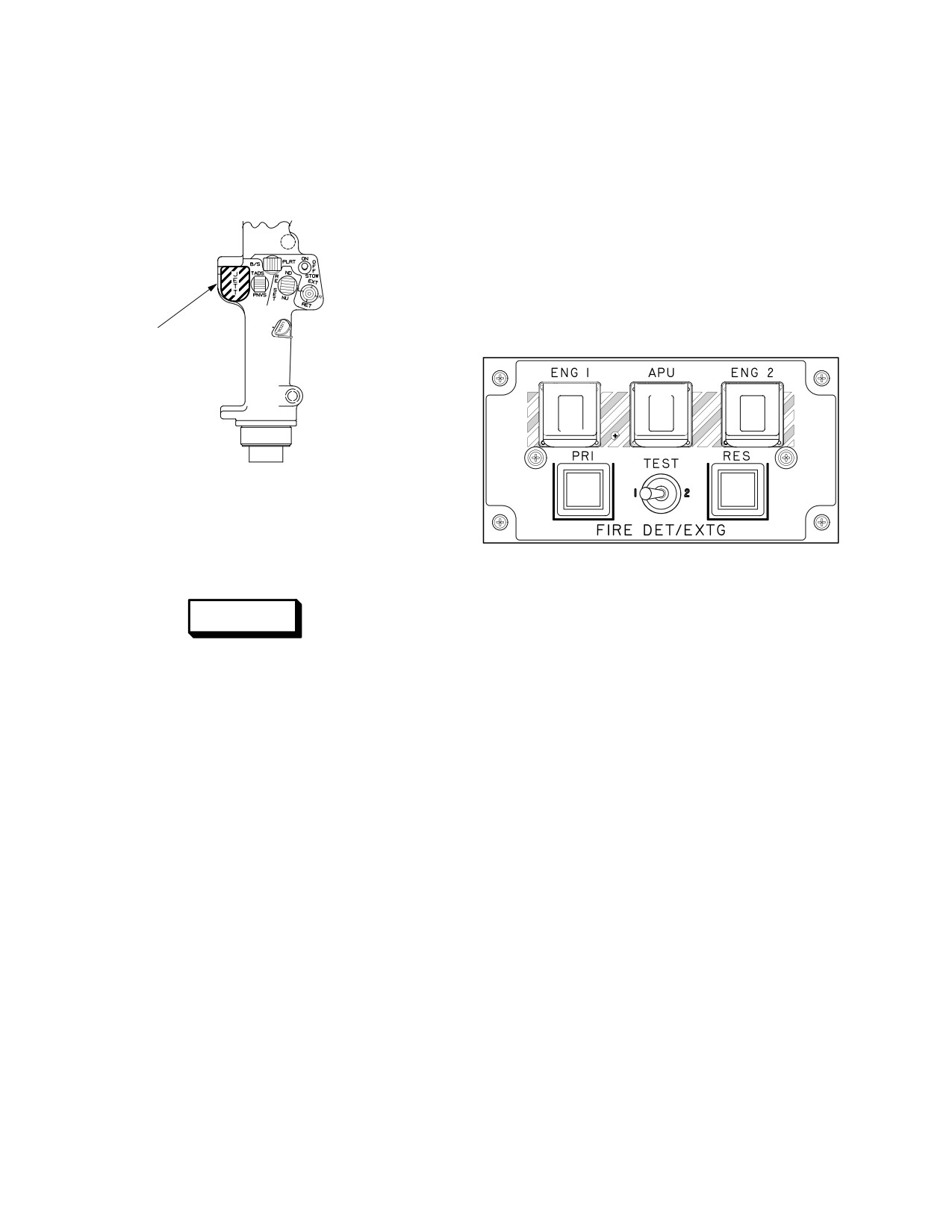
TM 1-1520-251-10
2.28.2
Emergency Stores Jettison
(JETT)
compartment. In case of a fire, amplified electrical signals
Switch. Pressing the guarded JETT switch on the flight
from the sensors illuminate the appropriate pushbutton
control section of the collective flight control grip (fig 2-38)
switch on the FIRE DET/EXTG panel (fig 2-39).
will cause all external stores to be jettisoned from the air-
2.30.1
Engine and APU Fire Extinguishing
craft at the same time.
Bottles. Fire extinguishing agent is stored in two spheri-
cal bottles each containing a nitrogen precharge. The
bottles, designated as primary (PRI) and reserve (RES),
are mounted on the fuselage side of the engine 1 firewall.
Bottle integrity may be checked by inspecting the thermal
relief discharge indicator disk (viewed from below the left
engine nacelle). A pressure gage on each bottle indicates
the nitrogen precharge pressure.
EMERGENCY
JETTISON SWITCH
(GUARDED)
ÔÔ
FIRE
FIRE
FIRE
RD
RDY
RDY
ÔY
ÔÔ
LBA0465
DISCH
DISCH
Figure 2-38. Emergency Stores Jettison (JETT)
Switch
LBA2547
2.29 PORTABLE FIRE EXTINGUISHER
Figure 2-39. Fire Detection/Extinguishing Panel
WARNING
2.30.2 Fire Detection/Extinguishing (FIRE DET/EXTG)
Panel. Each crew station contains a FIRE DET/ EXTG
Exposure to high concentrations of fire
panel. FIRE warning lights are combined with Ready
extinguishing agent or decomposition
(RDY) lights in alternate action pushbutton switches. The
products should be avoided. The gas
FIRE/RDY pushbutton switches have hinged cover
should not be allowed to contact the
guards to prevent inadvertent actuation. The color of each
skin; it could cause frostbite or low tem-
legend is NVIS yellow. The RDY, Primary (PRI) Discharge
perature burns. If agent comes in contact
(DISCH), and Reserve (RES) DISCH legends are NVIS
with the skin, seek medical help immedi-
green. The PRI DISCH and RES DISCH lights are mo-
ately.
mentary action pushbutton switches.
A pressurized fire extinguisher is mounted on a quick re-
NOTE
lease support located in the Extended Forward Avionics
Bay (EFAB) fairing aft of the right EFAB access door and
When positioning the fire detection test
above the main landing gear wheel. It is accessible
switch to position 1 or 2, hold the test switch
through a hinged access panel which is marked FIRE EX-
in the TEST position for approximately 2 se-
TINGUISHER INSIDE. The fire extinguisher compound is
conds before releasing it to the spring
released by a hand operated lever located on top of the
loaded center position (OFF) to ensure full
extinguisher. Inadvertent discharge of the bottle is pre-
voice warning activation. If the above proce-
vented by a breakaway safety wire across the actuating
dure is not followed, the crew will not receive
lever. Operating instructions are printed on the fire extin-
a proper response to the test initiation and
guisher.
may not receive a full voice warning reply of
all circuits.
2.30 ENGINE AND APU FIRE DETECTION/
a. Fire Detection Circuit TEST Switch. The TEST
EXTINGUISHING SYSTEM
switch is a three position toggle switch used to test fire
Two optical sensors, which react to visible flames are lo-
detection circuits 1 and 2. The switch is spring loaded to
cated in each engine compartment and in the APU
center (OFF) position.
Use or disclosure of this information is subject to the restriction(s) on the title page of this document.
2-28
Change 2
TM 1-1520-251-10
Placing the TEST switch in the left (1) position tests one-
c. Fire Extinguisher Discharge (DISCH) Lighted
half of the fire detection circuit for each engine, the APU,
Push Button Switches. When a FIRE pushbutton has
and the aft deck overheat sensors, and tests the master
been armed and the RDY light is ON, pressing the illumi-
warning light and voice warning. All three FIRE switches
nated PRI DISCH pushbutton will discharge the primary
illuminated confirms all circuits are operable.
fire bottle and extinguish the DISCH light, indicating the
primary fire bottle has discharged and is no longer avail-
Placing the TEST switch in the right (2) position tests the
able. If this fails to extinguish the fire and the FIRE light is
other half of the fire detection circuit in the same manner.
still illuminated, pressing the illuminated RES DISCH
All three FIRE switches and both DISCH switches illumi-
pushbutton will discharge the reserve bottle and extin-
nated confirms all circuits are operable.
guish the DISCH light, indicating the reserve fire bottle is
Failure of a pushbutton to illuminate or a voice warning to
discharged and no longer available.
annunciate during either test indicates a fault in the circuit
2.30.3 Aft Deck Fire. Three pneumatic fire/overheat
being tested.
detectors are located in the aft deck area. One detector is
b. FIRE Lighted Pushbutton. The FIRE pushbut-
mounted on the main transmission support, and one on
ton is used to isolate a fire and arm that area’s fire extin-
each of the two firewall louver doors. A transmission aft
guishing system. When sensors detect a fire in either en-
deck fire warning is provided by crewstation voice mes-
gine nacelle or the APU compartment, the FIRE
sage, flashing master warning pushbutton, UFD/EUFD
pushbutton legend associated with that area will illumi-
and MPD warning messages. There is no extinguishing
nate in both crewstations along with the master warning
agent for the aft deck area.
light and voice warning. When the warning occurs, the
MPD will autopage to the ENG Emergency format.
2.31 FIRST AID KITS
The helicopter is equipped with two first aid kits, one on
WARNING
the inside aft portion of the pilots right canopy panel and
one on the lower side of the CPGs left console. The loca-
• Ensure the aircraft controls are con-
tion of the first aid kits is shown in Chapter 9.
figured for single engine operation
prior to pressing the illuminated FIRE
2.32 MASTER ZEROIZE SWITCH
pushbutton.
• Pressing the FIRE pushbutton (wheth-
er illuminated or not) will shut off the
CAUTION
fuel to the selected engine or APU.
This action can only be reversed from
The use of the MASTER ZEROIZE switch
within the same crewstation.
is a ”Last Ditch” procedure that should
be used only when the compromise of
(1) Pressing the illuminated FIRE pushbutton will
classified information to hostile forces is
arm the fire extinguishing system, shut off fuel flow to the
imminent. This procedure causes physi-
indicated engine or APU, shut off bleed air from the indi-
cal damage to aircraft circuit cards, and
cated engine or APU, close the cooling louvers to the indi-
should not be used as a normal opera-
cated engine, turn off the voice warning message, and
tion procedure.
turn off the master warning light. When the RDY light is
ON, the system is armed.
The MASTER ZEROIZE switch (fig 2-40), located on the
right side instrument panel in pilot and CPG stations, is a
(2) Pressing the same FIRE pushbutton a second
toggle switch covered by a red guard secured with safety
time (in the same crew station) will reverse the above
wire. MASTER ZEROIZE erases all DTC data and all
functions and disarm the fire extinguishing system.
FCR data including FCR programming from non - volatile
memory (NVM). It includes a destructive zeroize of the
NOTE
non-volatile memory of the FCR Programmable Signal
The FIRE switches will remain illuminated
Processor (PSP) in addition to the data listed in the de-
until the sensors no longer detect a fire. For
scription of the EMERGENCY panel ZEROIZE switch in
a crewstation to discharge or reset the sys-
Chapter 3. MASTER ZEROIZE does not zeroize any of
tem, that crewstation FIRE pushbutton must
the User Data Modules (UDM). In order to zeroize, the air-
be armed/dearmed.
craft must have power and the FCR must be ON.
Use or disclosure of this information is subject to the restriction(s) on the title page of this document.
Change 2
2-29

TM 1-1520-251-10
be removed and stowed during normal flight. The trans-
mitter transmits an intermittent tone at 121.5 MHz and
243.0 MHz simultaneously.
ARM
OFF
ON
TEST
FOR AVIATION
LBA2136
EMERGENCY USE ONLY
LBA5502
Figure 2-40. Master Zeroize Switch
Figure 2-40A.
[
BLK 2
Emergency Locator
2.33 SURVIVABILITY EQUIPMENT
Transmitter]
[
BLK 1
Survivability equipment includes a CBR Blow-
er.] [
Survivability equipment includes a CBR
The OFF - TEST/ARM/ON switch is a three position switch
BLK 2
Blower, Emergency Locator Transmitter and Underwater
that is spring loaded from the OFF - TEST position to the
Acoustic Beacon.]
ARM position. It must be manually placed in the ON posi-
tion or to the ARM position from the ON position.
2.33.1 CBR Blower. The Chemical, Biological, Radio-
logical Filter/Blower (CBR) blower system is capable of
NOTE
providing filtered air to the flight crew, when the cockpit air
Transmitter test shall only be performed dur-
supply is believed to be contaminated. Each crewmember
ing the first five minutes after the hour.
carries his own CBR mask on board. The CBR mask is at-
tached to the external power source located on the left
The OFF - TEST position has two functions:
side of the crew seat in each crew station.
(1) To turn the transmitter off.
(2) To check power output (battery condition).
2.33.2
[
BLK 2
Emergency Locator Transmitter
(ELT)]. The ELT is provided to allow search/rescue
The ARM position allows for the ELT to start transmitting
teams to locate the aircraft and/or the crew. The ELT can
(if shorting plug is removed) if either of the G-switches
be actuated either by internal gravity switches (crash) or
(360 degree and/or vertical switch) are actuated.
manually using the OFF-TEST/ARM/ON switch (fig
2-40A). The ELT is located behind the CPG seat on the
The ON position allows for transmitting manually.
right side. It can be removed, as required, and carried with
the crew. The ELT is battery operated and fully self-con-
2.33.3 [
BLK 2
Underwater Acoustic Beacon]. The
tained. The ELT is equipped with a lanyard that has an at-
UAB is provided to allow search/rescue teams to locate
tached shorting plug. The shorting plug is used to de-acti-
the aircraft if it has been ditched. The UAB is actuated by
vate the gravity switches. The shorting plug should be
water (salt or fresh). The UAB is located forward of the pi-
installed at all times except when flying (at the discretion
lot’s left control pedal. The UAB is is battery operated and
of flight crew). Installing the shorting plug eliminates acci-
completely self-contained. When actuated, the UAB
dental activation of the transmitter. The shorting plug must
transmits at 37.5 KHz.
Use or disclosure of this information is subject to the restriction(s) on the title page of this document.
2-30
Change 2
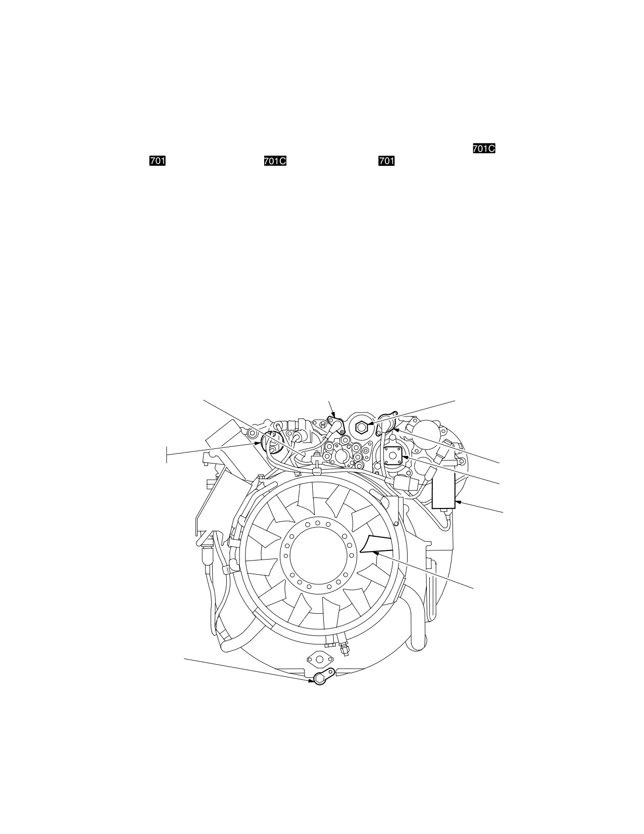
TM 1-1520-251-10
Section III. ENGINES AND RELATED SYSTEMS
2.34 ENGINES
and variable stage 1 and stage 2 stator vanes. Compo-
nents mounted on the cold section module are: the Digital
Electronic Control (DEC)
/Electronic Control Unit
The T700-GE-701
and T700-GE-701C
engines
(ECU)
, history recorder/history counter, ignition sys-
(fig
2-41) are front drive turboshaft engines of modular
tem, and electrical cables as well as the accessory section
construction. One horizontally mounted engine is housed
module.
in an engine nacelle on each side of the fuselage aft of the
main transmission above the wing. The engine is divided
2.36 HOT SECTION MODULE
into four modules: cold section, hot section, power turbine
section, and accessory section.
The hot section module consists of three subassem-
blies: the gas generator turbine, the stage 1 nozzle as-
sembly, and the annular combustion liner.
2.35 COLD SECTION MODULE
2.37 POWER TURBINE SECTION MODULE
The cold section module includes the main frame, diffuser
and mid frame assembly, the inlet particle separator, the
The power turbine module includes a two stage power tur-
compressor, the output shaft assembly, and associated
bine and exhaust frame. Mounted on the power turbine
components. The compressor has five axial stages and
module is the thermocouple harness, the torque and over-
one centrifugal stage. There are variable inlet guide vanes
speed sensor, and the NP sensor.
ALTERNATOR
OIL FILTER BYPASS SENSOR
OIL FILTER IMPENDING BYPASS BUTTON
OIL PRESSURE
SENSOR
CHIP DETECTOR
FUEL PUMP
FUEL FILTER
SWIRL VANES
OIL DRAIN PLUG
FRONT VIEW
LBA0104
Figure 2-41. T700-GE-701 / T700-GE-701C Engine (Sheet 1 of 2)
Use or disclosure of this information is subject to the restriction(s) on the title page of this document.
2-31
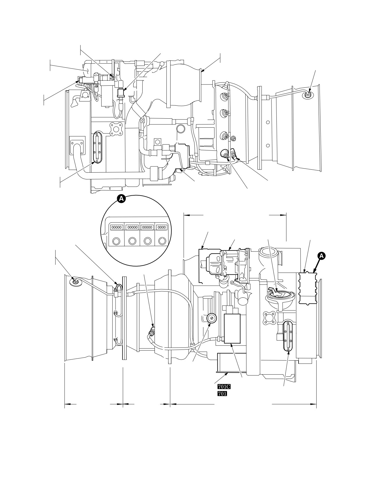
TM 1-1520-251-10
FUEL FILTER IMPENDING
FUEL PRESSURE SENSOR
BYPASS BUTTON
INLET PARTICLE
NP
OIL
SEPARATOR BLOWER
(% RPM)
COOLER
SENSOR
FUEL
PUMP
OIL LEVEL
IGNITOR PLUG
INDICATOR
ANTIICING AND
START BLEED VALVE
MAIN FUEL NOZZLE
LEFT SIDE VIEW
MODULE (INTERNAL)
ACCESSORY SECTION MODULE
HYDRO−MECHANICAL
UNIT
AIR
OIL FILLER
HISTORY
LCFI
LCF2
INDEX
HOURS
THERMOCOUPLE
TURBINE STARTER
CAP
RECORDER
HARNESS
TORQUE AND
OVERSPEED
SENSOR
IGNITER PLUG
BLEED AIR
PORT
IGNITION EXCITER
DEC
OIL LEVEL INDICATOR
ECU
POWER TURBINE
HOT SECTION
MODULE
MODULE
COLD SECTION MODULE
RIGHT SIDE VIEW
LBA0032
Figure 2 - 40. T700-GE-701 / T700-GE-701C Engine (Sheet 2 of 2)
Use or disclosure of this information is subject to the restriction(s) on the title page of this document.
2-32
TM 1-1520-251-10
2.38 ACCESSORY SECTION MODULE
nose gearbox fairing is an electrically heated fairing to
prevent the formation of ice on each engine nose gearbox
The accessory section module includes the top mounted
fairing. Operation of the system may be automatic or
accessory gearbox and the following components: a hy-
manual. Engine anti-ice controls are described in section
IX.
dromechanical unit (HMU), a fuel boost pump, oil filter, oil
cooler, alternator, oil lube and scavenge pump, particle
separator blower, fuel filter assembly, chip detector, oil/fil-
2.42 ENGINE FUEL CONTROL SYSTEM
ter bypass sensors, oil/fuel pressure sensor, overspeed
and drain valve (ODV), and an air turbine starter.
The engine has a conventional fuel control system: power
control lever position and the degree of collective pitch ba-
2.39 ENGINE COOLING
sically establish the power output demands placed on the
engines. Engine power is trimmed automatically through
Each engine is cooled by air routed through the engine
interaction of the HMU and the ECU
/DEC
. The
nacelle. Airflow is provided by eductor pumping action of
ECU
/DEC
of each engine exchanges torque sig-
the infrared suppressor. Fixed louvers on the top and bot-
nals with the opposite engine to achieve automatic load -
tom of the aft portion of each nacelle and movable doors
sharing between engines.
in the bottom forward portion of each nacelle accelerate
convection engine cooling after shutdown. The movable
door is shut by engine bleed air pressure during engine
2.42.1 Fuel Boost Pump. A low-pressure suction fuel
operation and is spring loaded to open during engine
boost pump is installed on the front face of the engine ac-
shutdown.
cessory gearbox. It ensures that the airframe fuel supply
system is under negative pressure, thus reducing the dan-
ger of fire in case of fuel system damage. If the ENG 1
2.40 AIR INDUCTION SYSTEM
FUEL PSI or ENG 2 FUEL PSI caution message appears
at idle speed and above, it could indicate a leak or restric-
The engines receive air through a bell mouth shaped na-
tion in the helicopter fuel system or a failed engine boost
celle inlet at the front of the engine. Air flows around the
pump.
nose gearbox fairing before entering the engine nacelle
inlet. From the inlet, air continues through canted vanes in
the swirl frame where swirling action separates sand,
2.42.2 Fuel Filter. A fuel filter is located between the
dust, and other particles. Separated particles accumulate
fuel boost pump and the high-pressure pump in the HMU.
by centrifugal force in a scroll case. The particles are
If this filter becomes clogged and impedes the passage of
ejected overboard via a blower which forces them through
fuel, a bypass valve permits fuel to bypass the filter. The
a secondary nozzle of the infrared suppression device.
differential pressure initiating bypass actuates the fuel-
Clean air, meanwhile, has passed through a swirl vane
pressure bypass sensor, thus causing the FUEL1 BYP or
which straightens the airflow and channels it into the com-
FUEL2 BYP caution to appear. An impending filter bypass
pressor inlet.
button on the filter housing pops out when filter element
differential pressure indicates impending bypass.
2.41 ENGINE AND ENGINE INLET ANTI-ICING
SYSTEM
2.42.3
Hydromechanical Unit.. The HMU provides
metered fuel to the combustor to control the gas generator
(NG) speed. The
HMU contains a high pressure fuel
CAUTION
pump to supply fuel to the metering section. The HMU re-
sponds to mechanical inputs from the aircrew through the
To prevent damage to the engines, the
power available spindle (PAS) and the load demand
engine anti-ice system shall be manually
spindle (LDS). The PAS is mechanically connected to the
activated when the aircraft is flown in
pilot’s
power levers while the LDS is connected to a bell-
visible moisture and Free Air Tempera-
crank attached to the collective servo. The HMU regulates
ture (FAT) is less than +41 °F / +5 °C.
fuel flow and controls positioning of the inlet guide vanes,
variable compressor stage 1 and 2 vanes as well as the
The engine anti-ice system includes the engine, the en-
anti-ice and start bleed valve in response to engine inlet
gine inlet fairings, and the nose gearbox fairings. Engine
air temperature, compressor discharge air pressure, NG
fifth stage bleed air is used to heat the swirl vanes, nose
speed, PAS and LDS positioning, and the ECU
, DEC
splitter, and engine inlet guide vanes of each engine. The
Use or disclosure of this information is subject to the restriction(s) on the title page of this document.
2-33
TM 1-1520-251-10
The HMU will additionally provide NG overspeed protec-
2.43.2 Engine TGT Limiter Function
The ECU
tion in the event the gas generator exceeds 108 - 112%.
incorporates a steady state dual and single TGT limiting
When an NG overspeed is sensed, fuel flow to the com-
function which restricts fuel flow within the HMU to prevent
bustor is stopped within the HMU which causes the en-
engine overtemperature. The limiting function has an in-
gine to flame out.
herent +/ - 4° C variance factor. In addition to the limiter
variance, the resistance in the cabling and circuitry be-
tween the ECU and the SP, DP, and MPD ENG page is
2.42.4 Overspeed and Drain Valve (ODV). The ODV
enough to produce a +/ - 8° C variance factor. Applying the
responds to a signal from the ECU/DEC. Under normal
sum of these two factors, the dual engine limiter setting is
operation, fuel is routed from the HMU via the oil cooler
allowed a value of 860 +/ - 12 (848 - 872)° C and the single
and through the ODV to the combustor. When an NP over-
engine (contingency power) limiter setting is allowed a
speed condition is sensed, a signal from the ECU
/
value of 917 +/ - 12 (905 - 929)° C. The TGT limiter setting
DEC
closes a solenoid in the ODV, thus routing fuel
for a particular engine can change within these ranges
back into the HMU. All residual fuel is drained overboard.
over a period of time.
Fuel flow to the fuel manifold ceases, and the engine
flames out.
2.43.3 Digital Electronic Control
The DEC is
mounted in the same location as the ECU. The DEC can
be overridden like the ECU by momentarily advancing the
2.43 ENGINE ELECTRICAL SYSTEM
engine POWER lever to LOCKOUT. The DEC, which in-
corporates improved technology, performs the same func-
2.43.1 Electrical Control Unit
The ECU controls
tions as the ECU except for the following functional and
the engine and transmits operational information to the
control improvements. The DEC can be fully powered by
crew stations. It is a solid-state device mounted below the
either the engine alternator or by 400 Hz, 120 Vac aircraft
engine compressor casing. Powered by the engine alter-
power. It incorporates logic which will eliminate torque
nator, the ECU receives inputs from the thermocouple
spike signals during engine start-up and shutdown. The
harness, NP sensor, torque and overspeed sensor, oppo-
DEC control logic contains a Maximum Torque Rate At-
site engine torque for load sharing, NG signal from the al-
tenuator (MTRA) feature designed to reduce the risk of
ternator, NP reference signal from the turbine speed con-
exceeding the dual engine torque limit during uncompen-
trol unit, and a feedback signal from the HMU for system
sated maneuvers. These are any maneuvers where pedal
stabilization. The torque-sharing system increases power
or cyclic inputs are made but no collective control input oc-
on the lower-output engine to match it with the higher out-
curs. For example, large transient engine torque increase
put engine. The ECU also receives opposite engine
can occur during left pedal and left lateral cyclic inputs
torque inputs to enable contingency power. When this in-
when performing maneuvers such as rapid hovering turns
put signal is 51% torque or below, contingency power is
or forward flight roll reversals. The MTRA is designed to
automatically enabled. However, contingency power is
reduce fuel flow and limit rate of torque increase to
not applied until the flight crew pulls in collective above
approximately 12% per second when transient engine
867 °C TGT. The ECU automatically allows the normally
torque exceeds 100% during an uncompensated maneu-
operating engine to increase its TGT limit, thereby in-
ver. However, any collective control increase during the
creasing its torque output. The overspeed protection sys-
maneuver can override the MTRA and normal maximum
tem senses a separate NP signal independently of the
engine torque rate increase can be achieved. The MTRA
governing channel. ECU also provides signals to the NP
feature is not active in the DEC logic under single engine
indicator, TORQUE indicator, and history recorder. In case
conditions. The DEC contains an automatic hot start pre-
of the ECU malfunction, system operation may be overrid-
venter (HSP). The DEC also provides signal validation for
den by momentarily advancing the engine POWER lever
selected input signals within the electrical control system.
to LOCKOUT and then retarding the lever past the FLY
Signals are continuously validated when the engine is op-
position to manually control engine power. This locks out
erating at flight idle and above. If a failure has occurred on
the ECU from all control/limiting functions except NP over-
a selected input signal, the failed component or related
speed protection, which remains operational. To remove
circuit will be identified by a pre - selected fault code. Fault
the ECU from lockout operation, the engine POWER lever
codes (Table 2-1) will be presented on the engine torque
must be moved to IDLE, then back to FLY.
display located on the aircraft ENG page.
Use or disclosure of this information is subject to the restriction(s) on the title page of this document.
2-34
TM 1-1520-251-10
Fault codes will be displayed starting with the lowest code
value of 896 +/ - 12 (884 - 908)° C. The TGT limiter setting
for four seconds on/two seconds off, rotating through all
for a particular engine can change within these ranges
codes and then repeating the cycle. The fault codes will
over a period of time.
be displayed on the engine torque vertical tape and digital
display only when all of the following conditions are met:
2.43.5 Hot Start Prevention
The hot start pre-
• NG less than 20 percent
vention (HSP) system is a part of the DEC and prevents
overtemperature during engine start. The HSP system re-
• NP less than 35 percent
ceives power turbine speed (NP) signal, gas generator
speed (NG) signal, and turbine gas temperature (TGT).
• Other engine shutdown
When NP and NG are below their respective hot start ref-
• Aircraft 400 Hz power available
erence, and TGT exceeds 900° C an output from the HSP
system activates a solenoid in the overspeed and drain
The fault codes can be suppressed by pressing either
valve. This shuts off fuel flow and causes the engine to
OVSP TEST switch. The fault codes can be recalled by
shut down. The HSP system will not operate if aircraft 400
again pressing either OVSP TEST switch. Once a failure
Hz power is not present at the DEC. The HSP system can
has been identified, the fault code will remain available for
be turned off by pressing and holding either OVSP TEST
diagnostic indication until starter dropout on the next en-
switch during the engine starting sequence.
gine start.
2.43.6 Fuel Pressure Warning System. The engine
fuel pressure warning system for each engine consists of
Table 2-1. Signal Validation - Fault Codes
a pressure switch that will cause the ENG1 FUEL PSI or
ENG2 FUEL PSI caution messages to be displayed when
Signal Failed
Diagnostic indication on
fuel pressure drops below 8 psi.
Torque Display
(± 3% Tolerance)
2.43.7 Engine Alternator
The engine alternator
DEC
15%
supplies AC power to the ignition circuitry and the ECU for
NP Demand Channel
25%
its control functions. Additionally, it also provides the NG
speed signal to the aircraft. When the alternator power to
Load Share
35%
the ECU is lost, a loss of NP
and torque indications will oc-
TGT Channel
45%
cur on the affected engine,and the engine will increase to
Alternator Power
55%
maximum power; ENGINE 1 OR ENGINE 2 OVER-
SPEED - NP FAILED HIGH emergency procedure. Air-
NG l Channel
65%
craft 400 Hz, 115 Vac power is provided as a backup to the
NP Channel
75%
engines to ensure operation of the NP overspeed protec-
tion circuitry. Aircraft backup power will not prevent an en-
Torque and Overspeed
85%
Channel
gine overspeed if an engine alternator fails, but it does en-
sure that the overspeed protection circuitry is powered to
Hot Start Prevention
95%
shut down the engine if overspeed limits are reached. If
Channel
the portion of the engine alternator providing the signal to
Aircraft 400Hz Power
105%
the aircraft is lost, the Ng indication for the affected engine
Collective Channel
115%
will be 00.0 %, the engine out warning for that engine will
be annunciated, and the capability to start that engine will
be lost.
2.43.4 Engine TGT Limiter Function
The DEC
incorporates a steady state dual and single TGT limiting
function which restricts fuel flow within the HMU to prevent
2.43.8 Engine Alternator
The engine alternator
engine overtemperature. The limiting function has an in-
supplies AC power to the ignition circuitry and DEC for its
herent +/ - 4° C variance factor. In addition to the limiter
control function. Additionally, it also provides the NG
variance, the resistance in the cabling and circuitry be-
speed signal to the aircraft. When the engine alternator
tween the DECU and the SP, DP, and MPD ENG page is
power to the DEC is lost, aircraft 400 Hz, 115 Vac power is
enough to produce a +/ - 8° C variance factor. Applying the
provided to prevent an engine overspeed condition. En-
sum of these two factors, the dual engine limiter setting is
gine operation and NP and torque signals are not affected.
allowed a value of 867 +/ - 12 (855 - 879)° C and the single
If the portion of the engine alternator providing the NG sig-
engine (contingency power) limiter setting is allowed a
nal to the aircraft is lost, the NG indication for the affected
Use or disclosure of this information is subject to the restriction(s) on the title page of this document.
2-35
TM 1-1520-251-10
engine will be 0.00 %, the engine out warning for that en-
a popped impending bypass button. As the pressure in-
gine will be annunciated, and the capability to start that
creases further, a caution message will be displayed on
engine will be lost.
the UFD/EUFD. During engine starting, with oil tempera-
ture below the normal operating range, pressure may be
high enough to close the oil filter bypass sensor switch. In
2.43.9 Ignition System. Each engine has an ignition
this situation, the advisory message will remain on until
exciter unit with two igniter plugs. The exciter unit receives
the oil warms up and oil pressure decreases. The impend-
power from its engine alternator. The MSTR IGN keylock
ing bypass indicator has a thermal lockout below 100° F
switch on the pilot engine power lever quadrant is an en-
(38° C) to prevent the button from popping.
abling switch to the ENG START switches. When an ENG
START switch is placed to START, pneumatic motoring of
2.44.4 Engine Chip Detector. Each engine chip detec-
the engine starter takes place and the ignition system is
tor is mounted on the forward side of the accessory gear-
energized. Ignition cutout is automatic after the engine
box. It consists of an integral magnet, electrical connector,
starts. Following aborted starts (Chapter 8, Operating
and a housing. A removable screen surrounds the mag-
Procedures and Maneuvers), the engine must be motored
net. The detector attracts magnetic particles at a primary
with the ignition system disabled. This is done by placing
chip detecting gap. If chips are detected, a message will
the ENG START switch to IGN ORIDE. Chapter 5 con-
be displayed on the UFD/EUFD. These chip detectors are
tains the starting cycle limitations.
of the non-fuzz burning type.
2.44 ENGINE OIL SUPPLY SYSTEM
2.45 ENGINE STARTING SYSTEM
Each engine is lubricated by a self-contained, pressur-
The engine uses an air turbine starter for engine starting.
ized, recirculating, dry sump system. Included are oil sup-
System components consist of the engine starter, a start
ply and scavenge pumps, an emergency oil system, an in-
control valve, an external start connector, check valves,
tegral oil tank, a filter, an oil cooler, and seal pressurization
controls, and ducting. Three sources may provide air for
and venting. An inline chip detector, located down stream
engine starts: APU bleed air, engine bleed air, or an ex-
of the scavenge pump, causes a caution message to be
ternally connected ground source. In any case, the start
displayed if metal chips are detected.
sequence is the same. With the MSTR IGN switch to
BATT, placing the ENG START switch momentarily to
START will initiate an automatic start sequence. An ENG1
2.44.1 Engine Emergency Oil System. Small oil res-
START or ENG2 START advisory message will appear
ervoirs, built into the engine oil sumps, are kept full during
when an engine start is initiated. Compressed air is then
normal operation by the oil pump. If oil pressure is lost, oil
directed through the start control valve to the air turbine
will bleed slowly out of these reservoirs and be atomized
starter. As the air turbine starter begins to turn, an overrun
by air jets thus providing an oil mist lubrication for the en-
clutch engages which causes the engine to motor. The
gine bearings for thirty seconds at 75% NG. A caution
starter turbine wheel and gear train automatically disen-
message will be displayed when oil pressure drops below
gage from the engine when engine speed exceeds starter
20 - 25 psi.
input speed. At approximately 52% NG, air to the starter
shuts off, and ignition is terminated. If the engine does not
2.44.2 Oil Tank. Pertinent oil grades and specifications
start, the POWER lever must be returned to OFF and the
are in Section XV. The filler port is on the right side of the
ENG START switch must be placed at IGN ORIDE (which
engine. The oil level is indicated by a sight gage on each
aborts the automatic engine start sequence) momentarily
side of the tank. Oil is supplied to the oil pump through a
before another start is attempted. Chapter 8 explains
screen. The scavenge pump returns oil from the sumps to
abort start procedures, and Chapter 5 contains the start
the oil tank through six scavenge screens.
cycle limits. If the engine is equipped with a DEC
,
fuel flow to the engine will be automatically shut off if TGT
2.44.3
Oil Cooler and Filter. Scavenge oil passes
exceeds 900 °C during the start sequence. If this occurs,
through an oil cooler before returning to the tank. It is
the POWER lever must be returned to OFF and the ENG
cooled by transferring heat from the oil to fuel routed
START switch must be placed in IGN ORIDE (which
through the cooler. If the oil cooler pressure becomes too
aborts the automatic engine start sequence).
high, a relief valve will open to dump scavenge oil directly
into the oil tank. Oil discharged from the oil pump is routed
2.45.1 APU Engine Start. The APU provides bleed air
through a disposable element filter. As the pressure differ-
for engine start. A complete description of the APU ap-
ential across the filter increases, the first indication will be
pears in Section XII.
Use or disclosure of this information is subject to the restriction(s) on the title page of this document.
2-36
Change 2
TM 1-1520-251-10
2.45.2 Engine Bleed Air Start. Either operating engine
manage engine power. The two quadrant control panels
bleed air may be used to start an engine that has failed in
are different, although the POWER levers are identical.
flight or engine not started by APU/AGPU during aircraft
Friction however, can be set on only the pilot levers. The
ground start. The single engine starting sequence is the
POWER levers have four detent positions: OFF, IDLE,
same as for APU/AGPU starting except; that the source of
FLY, and LOCKOUT. The pilot detent override controls
air pressure is provided by the operating engine. When
are mechanical while the CPG’s are electrically operated.
using this technique ensure adequate bleed air pressure
Movement of either POWER lever moves a cable to me-
is available by increasing collective pitch to a value that
chanically shut off fuel or to set NG speed. For flight, the
will increase NG of the bleed air source engine to a mini-
lever is advanced to FLY. By moving the POWER lever
mum of 95%.
momentarily to LOCKOUT, then retarding past FLY, NG
speed may be manually controlled. With the POWER le-
2.45.3 External Source for Engine Starting. An exter-
ver at LOCKOUT, the TGT limiting system is deactivated,
nal air receptacle under the No. 1 engine nacelle provides
and TGT must be closely monitored and controlled. The
an attachment point for an air line to start either engine
overspeed protection system is not disabled in the LOCK-
from an external source. The assembly contains a check
OUT position.
valve to prevent engine bleed air or IPAS pressurized air
from being vented overboard.
CAUTION
2.46 INFRARED (IR) SUPPRESSION SYSTEM
The IR suppression system consists of the primary nozzle
• Conditions permitting, POWER levers
and three secondary nozzles. The primary nozzle is
should be retarded to IDLE before re-
mounted to the engine exhaust frame and directs exhaust
setting CHOP button.
gases into the secondary nozzle. The three secondary
• Application of collective during CHOP
nozzles are attached and sealed to the engine nacelle.
operations will cause the Load De-
During engine operation, exhaust gases are cooled by air
mand system to allow the engines to
drawn through the transmission area by a low pressure
spool up.
area created by the eduction action of the primary nozzle.
Angles of the primary and three secondary nozzles pre-
• With the POWER levers in FLY, reset-
vents a direct view of the hot internal engine components.
ting the CHOP button will cause an er-
The cooler air is mixed with the hot air in the three second-
roneous ENG1 and ENG2 OUT warn-
ary nozzles cooling the exhaust gases.
ing to be activated.
2.47 ENGINE CONTROL SYSTEM
2.47.2 Pilot and CPG Engine Chop Control. A CHOP
The engine control system consists of the engine power
button is located on both the pilot and CPG collective flight
lever quadrant, the engine chop controls, the load de-
grips and is protected by a red spring loaded guard. When
mand system, and the overspeed protection system.
the engine CHOP button is pressed, the speed of both en-
gines is reduced to idle; and a warning message will ap-
2.47.1 Engine Power Lever Quadrant. The POWER
pear on the UFD/EUFD. The engine chop circuit is reset
lever quadrants (fig 2-42) allow either crewmember to
by pressing the CHOP button a second time.
Use or disclosure of this information is subject to the restriction(s) on the title page of this document.
Change 2
2-37
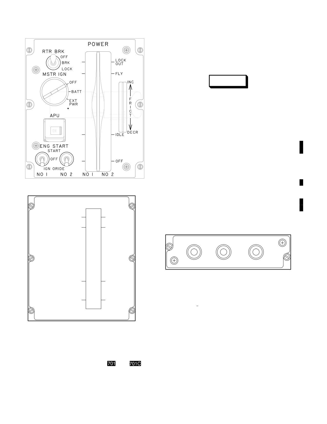
TM 1-1520-251-10
to LOCKOUT and then retarded to an intermediate posi-
tion, between IDLE and FLY, the engine will respond to
collective input, but control of engine speed is no longer
automatic and must be managed manually using the
POWER lever.
WARNING
The T700-GE-701 and T700-GE-701C en-
gine is designed to shut down when an
overspeed condition is sensed. The
OVSP TEST circuit trips at 95 - 97% NP
and should never be performed in flight.
Ó Ó
A power loss will result. Only mainte-
ÓÓ
nance is authorized to make this check.
ÓÓ
2.47.4 NP Overspeed Protection System. The over-
Ó Ó
speed protection system prevents turbine overspeed. The
system receives power turbine speed signals from the
torque and overspeed sensors located in the exhaust
frame. If the NP meets or exceeds 119.6"
1 %, two fre-
quency sensing circuits output a signal to the overspeed
PILOT POWER LEVER QUADRANT
LBA0463
system which causes the Overspeed Drain Valve (ODV)
to shut off fuel flow to the engine. Two overspeed test
Í
Í
switches are located on the CHK OVSP TEST/GEN RST
panel (fig 2-43). The switches, labeled CKTA and CKTB,
Í
POWER
Í
permit the use of two separate circuits to test each engine
Í
Í
in the normal power turbine speed range. The overspeed
LOCK
OUT
test switches are used during maintenance operational
FLY
checks.
Í
ÍÍ
CHK OVST TEST
GEN RST
ENG 1
Í
Í
Í
OFF
GEN 1
GEN 2
ÍÍ
ENG 2
Í
Í
CKT A
CKT B
Í
Í
Í
Í
LBA0020
IDLE
Figure 2-43. Check Overspeed Test/Generator
Reset Panel
OFF
2.48 ENGINE (ENG) PAGE INDICATION
Í
Í
NO. 1
NO. 2
Engine operational parameters are indicated on the En-
Í
Í
gine (ENG) page. The ENG page has three formats: a
PILOT POWER LEVER QUADRANT
LBA2541
“Ground” format, an “In-Flight” format and an “Emergen-
cy” format. Engine performance data is provided on the
Figure
2-42. POWER Lever Quadrants
PERF page and is described in Chapter 7. The controls
and displays necessary to establish engine and aircraft
torque factors (ETF/ATF) are located on the ETF page
2.47.3 Engine Load Demand System. When the en-
which is also described in Chapter 7.
gine POWER lever is in FLY, the ECU
/DEC
and
HMU respond to collective pitch position to automatically
2.48.1 ENG Page Ground Format. At aircraft power
control engine speed and provide required power. During
up, the left MPD in both crew stations defaults to ENG
emergency operations when the POWER lever is moved
ground format page (fig 2-44).
Use or disclosure of this information is subject to the restriction(s) on the title page of this document.
2-38
Change 2
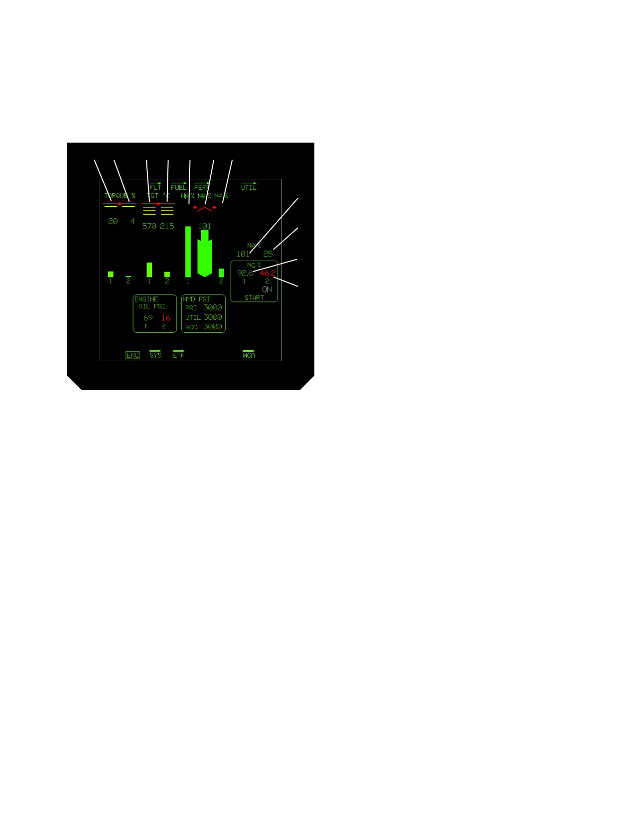
TM 1-1520-251-10
a. ENG Page Instruments. ENG page instruments
4.
Engine 2 Turbine Gas Temperature (TGT °C).
display torque, engine and main rotor indications in the
Tape/Digital Readout: 0° to 999 °C, resolution 1°.
upper area of the format (fig 2-44, Table 2-2). Operation of
5.
Engine 1 Power Turbine Speed (NP %).
these systems is indicated by color digital readouts and
Tape: 0 to 120 % RPM resolution 1%.
vertical tapes with operational limit markings.
6.
Main Rotor Speed (NR %).
1
2
3
4
5
6
7
Tape: 0 to 120% RPM, resolution 1%.
Digital Readout: 0 to 130%, resolution 1%.
7.
Engine 2 Power Turbine Speed (NP %).
8
Tape: 0 to 120% RPM, resolution 1%.
8.
Engine 1 Power Turbine Speed (NP %).
9
Digital Readout: 0 to 130%, resolution 1%.
9.
Engine 2 Power Turbine Speed (NP %).
Digital Readout: 0 to 130%, resolution 1%.
10
10. Engine 1 Gas Generator Speed (NG %).
Digital Readout: 0 to 120%, resolution 0.1%.
11
11. Engine 2 Gas Generator Speed (NG %).
Digital Readout: 0 to 120%, resolution 0.1%.
b. Ground Format Indications. The lower half of
the ENG page ground format displays engine oil pressure
and hydraulic pressure information in digital form (fig
2-45). The ground format will be displayed if the starter is
engaged during flight. The ENG page ground format dis-
LBA−30
plays the following system indications within the parame-
ters listed.
Figure 2-44. ENG Page Instruments
NOTE
The following descriptions of ENG page in-
dications give ranges of those displays. Re-
fer to Chapter 5 for system limits, instrument
markings, and restrictions.
Table 2-2. Engine Instruments Displays
1.
Engine 1 Torque (TORQUE %).
Tape: 0 to 130% resolution 1%.
Digital Readout: 0 to 255%, resolution 1%.
2.
Engine 2 Torque (TORQUE %).
Tape: 0 to 130% resolution 1%.
Digital Readout: 0 to 255%, resolution 1%.
3.
Engine 1 Turbine Gas Temperature (TGT °C).
Tape/Digital Readout: 0° to 999 °C, resolution 1°.
Use or disclosure of this information is subject to the restriction(s) on the title page of this document.
2-39
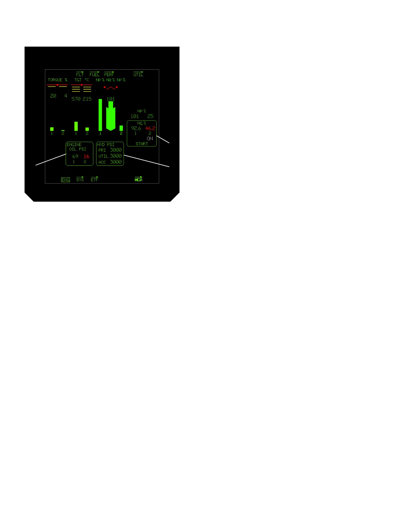
TM 1-1520-251-10
NOTE
Display of the HYD PSI status window takes
priority over the ENGINE OIL PSI status
window on the ENG page in - flight format.
2.48.2 ENG Page In-Flight Format.. The upper half of
the ENG page in-flight format (fig 2-46) displays the same
indications as the ground format. When both POWER le-
vers are advanced from IDLE to FLY, the ENG page auto-
matically changes from Ground format to In-flight format.
The lower half of the page will list active cautions in YEL-
LOW and warnings in RED as they occur, or display emer-
1
gency procedures when applicable.
3
2
LBA3002
Figure 2-45. Ground Format Indications
Table 2-3. Start, Engine Oil, Hydraulic Systems
Status
1. Start status (START) window. The START status
window and starter mode ON or OVRD label
(WHITE) will be displayed when the starter is
engaged.
2. Hydraulic pressure (HYD PSI) status window. The
Primary (PRI), Utility (UTIL), and Accumulator
(ACC) pressures will be displayed in the lower
area of the page on the ground format, and in the
upper right area of the in - flight format when
hydraulic pressure is less than 1260 psi or greater
than 3300 psi for more than 5 minutes or greater
than 3400 psi for more than 5 seconds.
Digital Readout: 0 to 6000 psi, resolution 10 psi.
3. Engine oil pressure (ENGINE OIL PSI) status
window. The engine 1 and 2 oil pressures will be
displayed in the lower area of the page on the
ground format, and in the upper right area of the
in - flight format when oil pressure is less than 23
psi or greater than 120 psi. Digital Readout: 0 to
255 psi, resolution 1 psi.
Use or disclosure of this information is subject to the restriction(s) on the title page of this document.
2-40
//////////////////////////