HELICOPTER, ATTACK, AH-64D LONGBOW APACHE. TECHNICAL MANUAL (2002) - page 5
TM 1-1520-251-10
3.53.10 RECEIVED MESSAGES.
a. REVIEWING RECEIVED ATHS MESSAGES.
There are three different ways to review a received mes-
NOTE
sage. To review a received message, follow one of the
procedures described:
ATHS - TACFIRE messages can only be
opened and viewed from the ATHS MSG
Procedure #1
RCV page. The COM IDM MSG RCV will
only allow for the deletion of an ATHS - TAC-
1. TSD page REC button (if the last message re-
FIRE message.
ceived is a tactical message) - Press as re-
quired. Upon selection of this button the page
The received message function of the IDM allows the ob-
will automatically switch to the RCVD MSG
server to access the received message list to review new
page.
messages. It also allows the observer to review and de-
lete any previously received messages, to include re-
2. Message to be reviewed - Select by pressing
ceived fire requests. When an ATHS - TACFIRE IDM mes-
button adjacent to appropriate message num-
sage is received, it will be stored in the RCVD MSGS
ber.
index of the IDM buffer and an ATHS message advisory
will appear on the MPD and UFD. An audible MODEM
3. Delete message as appropriate.
communication squelch is readily perceivable during the
message transmission and reception. Twelve messages
Procedure #2
(12 per ATHS - TACFIRE radio) can be stored for review
and deletion when desired, except for situation/status re-
1. COM page MSG REC button - Press as re-
ports which are automatically deleted upon review. Mes-
quired.
sages received while the RCVD MSGS index is full will not
be accepted, and the received advisory will not be dis-
2. Select TACFIRE message to be reviewed - Se-
played. When a message is received an acknowledge
lect by pressing button adjacent to appropriate
(ACK) is automatically transmitted back to the message
message number.
originator with no operator action required. Messages re-
ceived which are not recognizable, improperly addressed
3. RVW button - Press as required.
(net data incorrect), or unprocessable will be ignored. The
originator will not have an ACK displayed and an ATHS -
4. Review message.
TACFIRE MESSAGE will not be displayed to the receiver.
A message received which is acceptable, but from an
5. Delete message as appropriate.
originator not defined in the subscriber list, will be stored
and an advisory displayed; however, an ACK will not be
Procedure #3
transmitted back. A message received addressed to the
Team or Broadcast identifiers will be stored and an advi-
1. COM page ATHS button - Press as required. It
sory displayed but an ACK will not be sent to the origina-
is also possible to access ATHS button via the
tor. The RCVD MSG index will show the message num-
TSD RPT page.
ber, the identifier of the sender, a three character identifier
of message type, a six character field indicating the mes-
2. INDEX button - Press, as required, to display
sage content, and the status of the message. If the mes-
ATHS - TACFIRE INDEX page.
sage has been reviewed, delete (DEL) will appear next to
the right hand button line; if not yet reviewed, NEW will ap-
3. RCVD MSG line - key button - Press to display
pear. Another function of the received messages is that it
received message index.
allows the observer to leave the ATHS - TACFIRE pages
and still be able to manage a fire mission. The fire mission
4. Message to be reviewed - Select by pressing
summary pages will be automatically updated upon the
button adjacent to appropriate message num-
receipt of new mission commands. Received FREE TEXT
ber.
and movement messages can be deleted on the page that
they are reviewed. If delete is selected, the system will re-
5. Delete message as appropriate.
turn to the received message index page. Situation/status
reports are automatically deleted after they have been re-
6. To return to ATHS - TACFIRE index page, IN-
viewed and the information is stored in the status pages.
DEX button - Press.
Use or disclosure of this information is subject to the restriction(s) on the title page of this document.
3-65
TM 1-1520-251-10
b. ATHS MESSAGES. Table 3 - 3 lists all different
ATHS messages that can be displayed on the MSG REC
page.
Table 3-3.
ATHS Messages
TYPE OF MESSAGE
MESSAGE DISPLAYED ON THE MSC REC PAGE
Free Text
FREE TEXT T
Airborne Battle Damage Assessment/Casualty Report
BDA REPORT T
Airborne Situation Report
FARM REPORT T
Position Update Request
PP QUERY T
Position Update Reply
PP REPORT T
Airborne Mayday
MAYDAY REPORT
Airborne Movement Command
MOVE COMMAND
AIrborne Spot Report
SPOT REPORT
Airborne Negative Spot Report
NEG SPOT REPORT
Airborne Fire Request
AIR FIRE REQUEST
Airborne Mission Command
AIR FIRE REQUEST
Airborne Check All
AIR FIRE REQUEST
Airborne Target Position Update
AIR FIRE REQUEST
Artillery Intelligence Report
ARTY INTL GRID
Fire Request Grid
ARTY FIRE RQST
Fire Request Quick
ARTY FIRE RQST
Fire Request Shift
ARTY FIRE RQST
Forward Observer Command
ARTY FIRE RQST
Subsequent Adjust
ARTY FIRE RQST
End of Mission and Surveillance
ARTY FIRE RQST
Message to Observer
MSG TO OBSERVER
Observer Location
OBSERVER READY
Intialization Message
BULK MESSAGE
All Other Messages
ATHS MESSAGE
Use or disclosure of this information is subject to the restriction(s) on the title page of this document.
3-66
TM 1-1520-251-10
Section IIA.
HF
COMMUNICATIONS SUBSYSTEM
3.53A INTRODUCTION
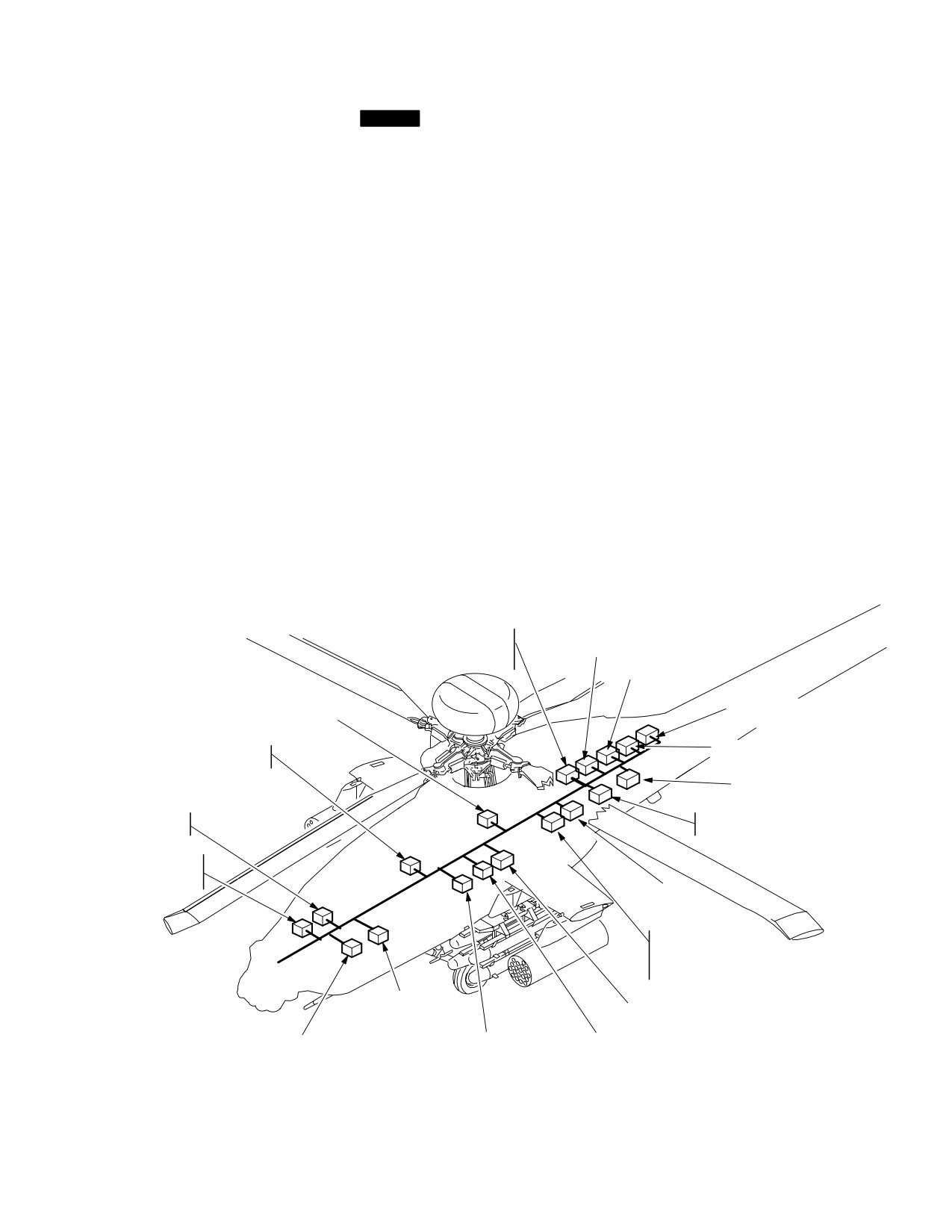
• Load Maintenance Panel (LMP) (COMSEC)
NOTE
This section covers the description and operation of the
aircraft communication subsystem and the Transponder/
The APX-100(V) Transponder or
IFF subsystem (fig 3-62A). Both voice and digital commu-
APX-118(V) may be installed. If
nications are supported by the following equipment:
APX - 100(V) is installed, Kit - 1C computer
must be installed for Mode 4 operation.
• ARC-186(V) VHF-AM Radio Set
• ARC-164(V) UHF-AM Radio Set (HAVEQUICK)
Each crewstation provides the crew with independent
• TSEC/KY-58 (CIPHER DEVICE)
control and status monitoring of the communication sub-
system via the Multi - Purpose Display (MPD), Up Front
• ARC-201D VHF-FM (SINCGARS) 2 each
Display (UFD) or Enhanced Up Front Display (EUFD),
• IFM-101A/AM-7189A/ARC Improved FM (IFM)
and Keyboard Unit (KU). In addition, monitor select and
Amplifier
volume/squelch controls for each of the five radios are
• ARC-220 HF Radio Set
controlled by the COMM panel in each crewstation. The
communication subsystem equipment is powered from
• TSEC/KY - 100 (HF CIPHER DEVICE)
the battery bus and defaulted to ON when power is ap-
• APX-100(V) Transponder
plied. However crew control of the radios is limited until
or
aircraft or external power is applied. After aircraft power
has been applied to the MPDs, rapid initialization of the
• APX-118(V) Transponder
radio presets and Signal Operating Instructions (SOI) can
• MD-1295/A Improved Data Modem (IDM)
be accomplished via the Data Transfer Unit (DTU).
AM1789A/ARC
ARC−186
IMPROVED FM
VHF−AM RADIO
AMPLIFIER
ARC−201D (FM2)
VHF−FM RADIO
SYSTEM
PROCESSOR q2
HF POWER AMPLIFIER
COUPLER
ARC−201D (FM1)
DATA TRANSFER
UNIT
VHF−FM RADIO
ARC220 HF RADIO
DISPLAY
ARC−164
PROCESSOR q2
UHF−AM RADIO
COMMUNICATION
INTERFACE
UNIT (CIU)
KY−58/TSEC
PROCESSOR
SECURE VOICE
KY−100/TSEC
PROCESSOR
SECURE VOICE / DATA
KIT−1C/TSEC
MD1295/A
IMPROVED DATA
TRANSPONDER
MODEM (IDM)
COMPUTER (WITH APX100)
SYSTEM
DISPLAY
APX−100(V) OR APX118(V)
PROCESSOR q1
PROCESSOR q1
IFF TRANSPONDER
LBA5080A
Figure 3-62A. Communications Subsystem
Use or disclosure of this information is subject to the restriction(s) on the title page of this document.
Change 3
3-66.1
TM 1-1520-251-10
3.53B ARC-186(V) VHF-AM RADIO SET
3.53C.1 Frequency Hopping (FH) Capability (HAVE
QUICK). The FH capability is an Electronic Counter-
Counter Measure (ECCM) enhancement to the standard
UHF radio by which the frequencies being used and the
The aircraft has one ARC-186 VHF radio which provides
dwell times are rapidly changed many times a second.
The radio requires three items to determine the FH pat-
two-way communication over VHF-AM frequency range
tern:
(116.000 through 151.975 MHz) in 0.025 MHz channel
spacing.
a. Time of Day (TOD). The TOD is synchronized to
the radio clock, which is normally set to Coordinated Uni-
versal Time (UTC). The TOD is required by the radio to
maintain its internal clock, which controls the FH timing.
NOTE
The crew may send or receive the TOD signal if FH com-
munication is desired through non - TOD synchronized ra-
dios. Receiving the TOD affects only the internal clock of
ARC-186 FM frequencies (30.000 through
the UHF radio.
87.975 MHz) are not implemented. See
b. Word of Day (WOD). The WOD is classified and
paragraph 3A.8
controlled by the National Security Agency (NSA). The
WOD programs the FH pattern and rate. The radio cannot
function in the FH mode without a valid WOD. A WOD is
required for each day and consists of up to six segments,
3.53B.1 VHF Tone. Selecting the VHF TONE button
which code the radio for FH. For HaveQuick 2 radios, the
will not generate a tone from the radio but will transmit a
WOD must be tagged with its operational day (1-31). The
”dead carrier” over the air for maintenance.
WODs are loaded into the radio through the DTU or by the
crew.
c. Net Number. The net number programs the radio
to operate in one of the FH modes, selects the frequency
3.53C ARC-164(V) UHF-AM RADIO SET (HAVE
table to be used and determines entry point into the FH
QUICK)
pattern. Net numbers enable multiple station pairs to op-
erate simultaneously using the same WOD and TOD with-
out interference. The net number will be loaded into the
radio through the DTU or via the crew.
The aircraft has one ARC-164 UHF radio which provides
3.53C.2 UHF Tone. Selecting the UHF TONE button
two-way communications over UHF-AM frequency range
generates an audio tone from the radio and transmits the
(225.000 through 399.975 MHz) in 0.025 MHz channel
tone over the air.
spacing. The radio contains a separate, dedicated guard
3.53D TSEC/KY-58 VOICE SECURITY SYSTEM
receiver fixed tuned to 243.000 MHz, thus providing capa-
bility to simultaneously monitor guard frequency (243.000
The aircraft has one TSEC/KY-58 Voice Security System
MHz) while receiving and transmitting on any frequency
for the UHF radio, which provides encrypted communica-
other than 243.000 MHz. When the transceiver is tuned to
tion. The TSEC/KY-58 has the capability to store up to six
Crypto Net Variables (CNV). CNVs are COMSEC vari-
243.000 MHz, the dedicated guard receiver is automati-
ables required to establish the encryption process inside
cally turned OFF. The radio set has squelch capability and
the TSEC/KY-58. CNVs are generally loaded directly into
can operate in either single channel or frequency hopping
the TSEC/KY-58 with a fill device by the maintenance
mode. The frequency hopping capability of the UHF radio
crew at the Remote Selectable Fill Port, but may also be
is referred to as HAVE QUICK. There can be one of two
loaded through RF Link. TSEC/KY-58 controls are imple-
versions of HAVE QUICK radios installed in the aircraft.
mented on the MPD and/or the EMERGENCY Panel and
HAVE QUICK 1 radios provide the capability to load one
the LMP.
word of day into the radio and utilize 6 training frequencies
3.53D.1 KY-58 Tones. The KY-58 generates tones for
for the training mode. HAVE QUICK 2 radios provide the
variable loading and failure conditions. An additional tone
capability to load up to six words of the day into the radio
is generated when the KY-58 is ready to transmit or re-
and utilize 16 training frequencies for the training mode.
ceive.
Use or disclosure of this information is subject to the restriction(s) on the title page of this document.
3-66.2
Change 3
TM 1-1520-251-10
3.53E AN/ARC-201D VHF-FM SINGLE CHANNEL
Table 3-3A. RF Output Levels
GROUND & AIRBORNE RADIO SET (SINCGARS)
Power Setting
Effective Radiating Power (Watts)
The aircraft has two ARC-201D VHF-FM radios. The radio
LOW
2.5
sets provide two-way communications over the VHF-FM
NORM
10.0
frequency range of 30.000 through 87.975 MHz in 0.025
MHz channel spacing. The radio set operates in either
HIGH
40.0
single channel or frequency hopping (FH) mode. The two
OFF
10.0
ARC-201D radios are referred to as FM1 and FM2 or, in
general, as FM. Secure voice/data communications are
The communications subsystem provides capability to set
provided by COMSEC equipment which is embedded in
IFM Power to LOW /NORMAL /HIGH /OFF via the MPDs.
the radios. Zeroizing the individual radio can be accom-
plished from the MPD.
3.53E.1 Frequency Hopping (FH) Capability. This
enhancement provides a FH capability (frequencies and
CAUTION
dwell times are rapidly changed many times a second).
• The IFM should be turned OFF when
FH provides an anti-jamming capability which can operate
operating the radios on battery power
in conjunction with a secure communications mode.
to avoid draining the aircraft battery.
Three items required to determine FH patterns are:
•
Transmitting IFM in HIGH while both
a. Time. Time is in the form: day, hour, and minutes.
FMs are tuned to the same frequency
Time is required by the radio to maintain its internal clock,
may cause damage to the FM2 receiv-
which controls FH timing.
er.
NOTE
b. Hopset. The Hopset is classified and controlled
Failure of the IFM will turn off the sidetone
by the NSA. The Hopset programs frequency hopping
from the ARC-201D FM1 radio. An IFM fail-
rate and frequency hopping pattern. The range of Hopsets
ure is also reported during radio IBIT. The
is between 001 - 999. There are up to six Hopsets loaded
FM1 radio may still be able to transmit at its
into the radio. Hopset information can be inserted locally
own internal power of 10 Watts. Should an
through the fill device with control provided by the load
IFM failure occur, it is recommended to turn
maintenance panel (LMP) and connected via the remote
IFM off.
selectable FILL port. It can also be distributed by Radio
3.53G AN/ARC-220 HF RADIO SET
Frequency (RF) link also known as ECCM Remote Fill.
The aircraft has one ARC-220 HF radio. The ARC - 220
provides High Frequency airborne communications in the
c. Lockout Set. During frequency selection for the
2.0000 through 29.9999 MHz frequency range, in 0.1 kHz
Hopsets, it may be determined that interference may re-
spaced steps. The ARC-220 operates in the following
sult between two nets using the same frequency. In this
modes:
case one of two types of lockouts, common or unique, is
• Manual tuning
automatically loaded when the system locally filled or
• Preset Channel tuning
through an ECCM Remote Fill.
• ALE (Automatic Link Establishment)
3.53F IMPROVED FM (IFM)
• ECCM Frequency Hopping
• Emergency
The Emergency mode is a preprogrammed configuration
The aircraft has one IFM amplifier to vary the RF power
of the ARC- 220 radio. The ARC - 220 radio will be referred
output of the FM1. The four power levels are listed in
to hereinafter as the HF radio. Refer to Table 3-3B for HF
Table 3-3A.
advisory and status messages.
Use or disclosure of this information is subject to the restriction(s) on the title page of this document.
Change 3
3-66.3
TM 1-1520-251-10
Table 3-3B. HF Radio Advisory/Status Message
3.53H KY - 100 HF RADIO COMMUNICATION
Table
SECURITY SYSTEM
Advisory/Status
Description
Message
The aircraft has one TSEC/KY - 100 Communications Se-
ANT TUNING
Radio is tuning the antenna
curity System which provides encrypted communications
for the HF radio. The TSEC/KY-100 transforms voice,
ANT UNTUNED
Radio ECCM net is not pre - tuned
digital data, or analog data into ciphertext information.
The TSEC/KY - 100 has the capability to store up to six
CALLING
An ALE call is being transmitted
Crypto Net Variables (CNV). CNVs are COMSEC vari-
ables required to establish the encryption process inside
CALL FAILED
ALE call has failed on all attempts.
the TSEC/KY-100. CNVs are generally loaded directly
into the TSEC/KY - 100 with a fill device at the Remote Se-
CALL RESPND?
ALE call detected: however, radio
lectable Fill Port, but may also be loaded through RF Link.
set to SILENT mode, crew must
TSEC/KY - 100 controls are implemented on the MPD.
press PTT to establish call.
CHECK MSG
Radio received text message: can
be reviewed and/or deleted.
3.53I APX-100 TRANSPONDER
FILL CHECK
Radio is checking fill data.
FILL PROCESS
Radio is processing fill data.
The aircraft contains one transponder, an APX-100 or
APX-118 (para 3.53J) which provides automatic radar
FILL RECVING
Radio is receiving fill data.
identification of the aircraft to all suitably equipped sta-
tions. The transponder receives, decodes, and responds
FILL WAITING
Radio is waiting for fill data.
to interrogation of the following modes:
GO DATA ONLY
Transmission quality poor, should
switch to data transmission only.
MODE 1
Provides 32 possible code
LINKED
ALE link established
combinations that can be selected
PP RECEIVED
Radio received a present position
in-flight. Possible code combinations
report; can be stored or deleted.
are: 00-03, 10-13, 20-23, 30-33, 40-43,
50-53, 60-63, and 70-73.
RECVING CALL
Incoming ALE call being received.
MODE 2
Provides 4096 possible code
combinations. The desired code must
RECVING DATA
Radio is receiving digital data.
be set on the ground on the APX-100
SOUNDING
Radio is sounding.
located behind access panel L160.
Possible code combinations are
SENDING DATA
Radio is sending digital data.
0000-7777.
MODE 3/A Provides 4096 possible code
SENDING TIME
Radio is sending the current time.
combinations that can be selected
in-flight. Possible code combinations
STANDBY
Radio is in standby mode.
are 0000-7777.
SYNCING
Radio is synchronizing.
MODE C Provides altitude information obtained
from the FMC.
TIME SYNC
Synchronized time between radios
FAIL
has failed
3.53I.1
KIT-1C MODE 4 Computer. Provides a crypto-
UNSYNC
Radio is currently not synchronized.
secure mode of identification for the APX - 100 transpond-
XMIT READY
Radio has transmitted ECCM
er by relying on an encrypted interrogation. It utilizes two
preamble and is ready to transmit.
classified operational codes which are loaded directly into
the KIT-1C computer via a fill device through the Remote
ZEROIZED
Radio is being zeroized.
Selectable Fill Port in the aft avionics bay. Code selection
Use or disclosure of this information is subject to the restriction(s) on the title page of this document.
3-66.4
Change 3
TM 1-1520-251-10
is limited to A or B, which corresponds to the operational
NOTE
day. Other MODE 4 capabilities are:
• KIT - 1C is not required in the aircraft with
• When on the ground, the MODE 4 HOLD
the APX - 118 transponder.
enables the computer to save the last
• When the KIT-1C is not installed in the
MODE 4 codes for utilization on the next
aircraft, the MODE 4 selection will not be
power-up
shown on the MPDs.
• IDENT selection located on the MPD and
COMM panel enables IDENT transmis-
3.53K IMPROVED DATA MODEM (IDM)
sion to ID ownship on others’ radar
screens
NOTE
• Selectable MODE 4 audio cueing
Testing has shown that reception ranges are
• Selectable MODE 4 EUFD visual cueing
often degraded by five NM or more over
• Selectable EMERGENCY mode
those ranges where voice communication
can be received.
3.53J APX-118 TRANSPONDER
The APX - 118 provides automatic radar identification of
The aircraft is configured with a single IDM, which sup-
the aircraft to all suitably equipped stations. The trans-
ports the digital communication requirements for Long-
ponder receives, decodes, and responds to interrogation
bow Air Force Application Program Development
of the following modes:
(AFAPD) and TACFIRE protocols. The IDM serves as the
digital host interface between the aircraft’s radios and the
MODE 1
Provides 32 possible code
data bus for specific mission equipment. IDM communica-
combinations that can be selected
tions occur over a crewmember’s selected digital radio
in-flight. Possible code combinations
channel. If a UFD is installed, a digital radio is selected by
are: 00-03, 10-13, 20-23, 30-33, 40-43,
RTS. If a EUFD is installed, the digital is selected by the
50-53, 60-63, and 70-73.
IDM transmit select indicator. Management of the IDM is
MODE 2
Provides 4096 possible code
performed through the communications subsystem.
combinations. Possible code
combinations are 0000-7777.
MODE 3/A
Provides 4096 possible code
combinations that can be selected
in-flight. Possible code combinations
are 0000-7777.
MODE 4
Provides a crypto - secure mode of
identification by relying on an encrypted
interrogation. It utilizes two classified
operational codes which are loaded
directly into the transponder via a fill
device through the Remote Selectable
Fill Port in the aft avionics bay. Code
selection is limited to A or B, which
corresponds to the operational day.
MODE C
Provides altitude information obtained
from the FMC.
MODE S
Growth provisions only.
Use or disclosure of this information is subject to the restriction(s) on the title page of this document.
Change 3
3-66.5
TM 1-1520-251-10
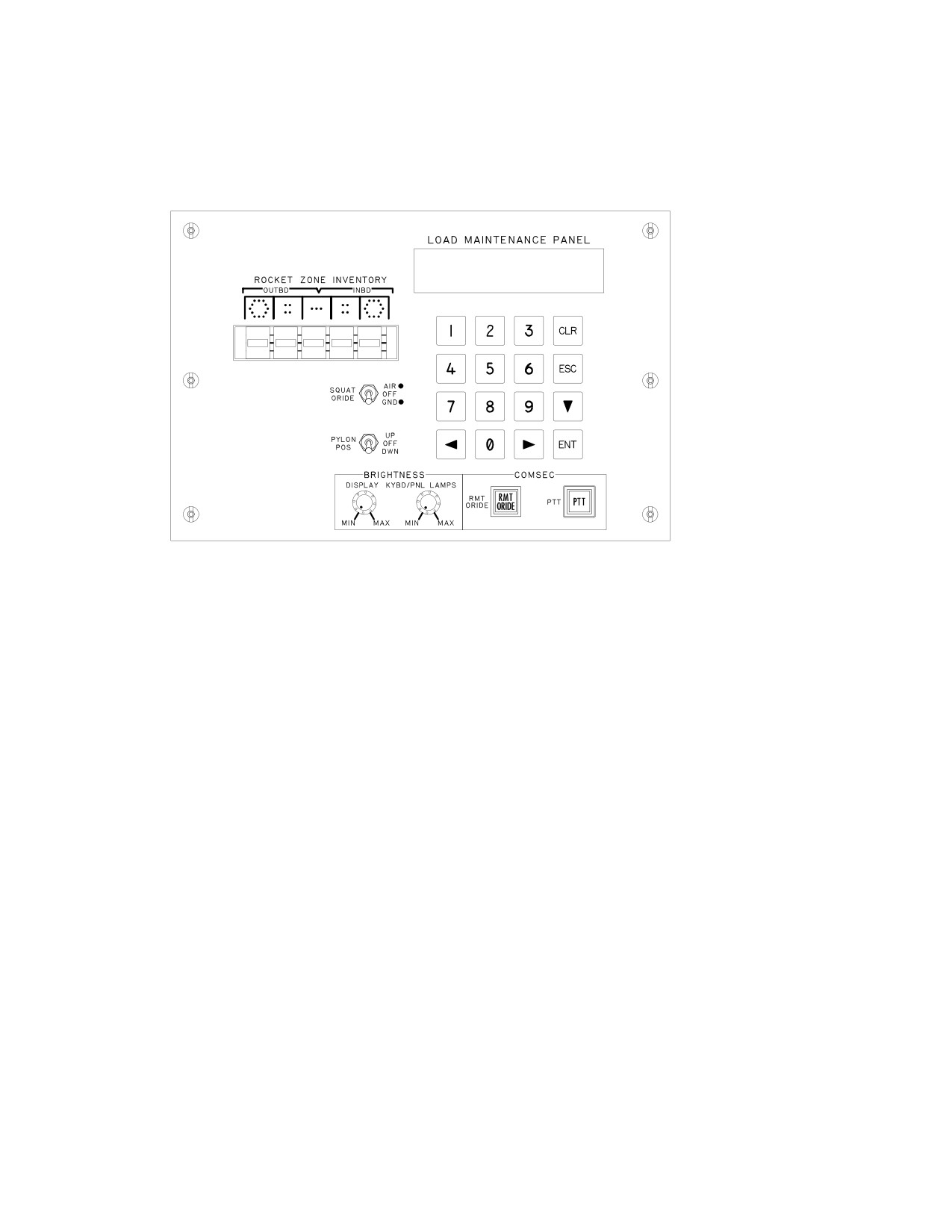
3.53L LOAD MAINTENANCE PANEL (LMP)
The LMP (fig 3-62B) consists of a keypad, display, front
panel control switches, and knobs. It is co-located in the
RH aft avionics bay with the Remote Selectable Fill Port.
1=RADIOS
3=GUNS
2=CRYPTOS
4=ASE
1:4:
6PD
6IL
6RC
6SK
6WP
LBA5081
Figure 3-62B. Load Maintenance Panel
3.53L.1 LMP Capabilities. The LMP provides the fol-
be manually actuated on the ground for any further load-
lowing capabilities:
ing.
• Position pylons for loading stores.
NOTE
• Override the SQUAT SWITCH setting to simulate
ICS communication is the only recom-
airborne conditions for troubleshooting and testing
mended communication during PTT opera-
while on the ground.
tions. Do not use UHF at this time.
• Display and specify rocket types associated with
3.53L.3 Press-To-Talk (PTT) Button. The PTT button
each of the aircraft rocket zones.
enables the transfer of Crypto Net Variable(s) from the Fill
device to the KY-58. This CNV transfer can be initiated by
• Display and specify 30mm Gun rounds count.
keying the appropriate radio from either crewstation.
• Display and specify Chaff count.
3.53L.4 LMP Lighting. To save power, all LMP dis-
• Specify data download to the FM radios.
plays and lamps are extinguished while airborne. After
landing, pressing any LMP keypad button reactivates the
• Specify/verify data download to the HF radios.
LMP displays and status lights. This initial key press is not
• Specify data download to the HF Radio’s Crypto
interpreted as a data entry keystroke.
device
3.53L.5 RADIO Selections. LMP provides the capabil-
• Press-to-talk (PTT) and Remote Override (RMT
ity to select the individual radio formats (1= FM1; 2= FM2;
ORIDE) COMSEC pushbuttons.
3= HF) for data fills and HF data verification. Selection of
the ESC key returns the operator to the index.
3.53L.2 Remote Override (RMT ORIDE) Button. The
RMT ORIDE button disables MPD control and enables
a. FM1 and FM2 Radio Fill Selections. The LMP
front panel (KY-58) control capabilities for Crypto Net Vari-
provides for frequency hopping and COMSEC variable fill
ables loading purposes. The RMT ORIDE button is auto-
selections via LMP keyboard. Selections are available for
matically disabled when the aircraft is airborne and must
the following fill device capabilities:
Use or disclosure of this information is subject to the restriction(s) on the title page of this document.
3-66.6
Change 3
TM 1-1520-251-10
• Single Hopset Preset
3.53M.1 RTS Push Button. When the RTS button is
actioned the UFD cycles through the crewmembers se-
• Single Lockout Set Preset
lected radios, automatically bringing up the next radio as
• Single COMSEC variable
the active transmitter.
• Complete set of Hopset/Lockout Set/COMSEC
3.53M.2 LAST Button. When the LAST button is ac-
tioned the last frequency shown on the right side of the
Single Hopset/Lockout Set/COMSEC variable filling re-
UFD is exchanged with current frequency and call sign on
quires two separate fill devices. A complete set of Hopset/
the left side of the display. RTS radios in both crewstations
Lockout Set/COMSEC variable filling can be achieved
are tuned to the last set frequency when the LAST button,
with a single fill device. LMP display feedback is provided
on the radio selected, is actioned.
for function in-progress, function completion, function
PASS and function FAIL status.
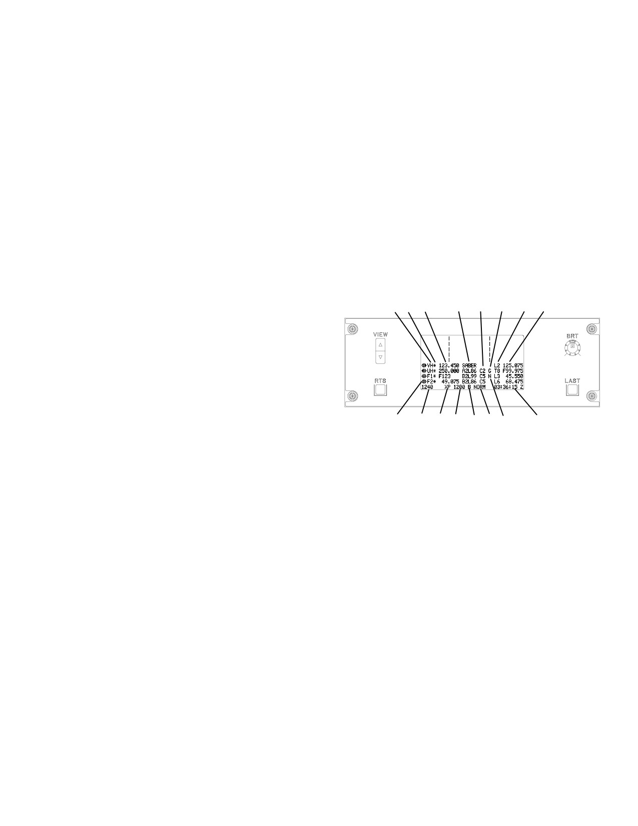
3.53N UFD COMMUNICATIONS FORMAT
b. HF Radio Fill Selections. The LMP provides for
The UFD is capable of displaying a select subset of the
keyfill, datafill, and verification selections via LMP key-
current status of the communication system as shown in
board. A fill device is required for both the keyfill and data-
figure 3-62C.
fill. The following selections are available from the LMP
with the HF radio option selected:
1
2
3
4
5
6
7
8
• Keyfill load
• Datafill load
• Verify keys
• Verify data
The VERIFY KEYS selection provides status of the key
load for LP3 (cipher for ECCM) and ECCM. The VERIFY
16
9
LBA0401A
15
14
13
12
11
10
DATA selection provides status of the datafill load. A dis-
play of the HF MODE CHANGE FAIL message indicates
Figure 3-62C. UFD Format
when the HF failed to change modes properly when com-
manded to perform a keyfill, datafill, verify keys, or verify
data. The datafill load verification and return code in-
UFD communications symbology are:
cludes:
1. Radio identifier (VH, UH, F1, and F2).
• PRE OP (operable), ND (no data), NK (no
keys)
2. Squelch (OFF/ON) status (asterisk indicates
• LP3
OP, ND, NK
squelch on).
• ECCM OP, ND, NK
3. Currently tuned frequency/FH parameters.
• MAN OP, ND, NK
• ALE
OP, ND, NK
4. CALL SIGN assigned to the currently tuned fre-
quency.
• EMER OP, ND, NK
3.53L.6 LMP CRYPTO Selection. The LMP CRYPTO
5. Cipher (OFF/ON) status and Crypto Net Vari-
selection provides the capability to access the formats for
able (UHF, FM 1, and FM 2 only).
selecting the installed individual crypto devices for key
fills.
6. Guard (G) receiver (OFF/ON) (UHF only).
3.53M UP FRONT DISPLAY (UFD) COMMUNICATION
7. IDM Net Status.
CONTROLS
8. Last tuned frequency.
UFD communication controls are the RTS pushbutton and
LAST pushbutton.
9. Current time (Local or Zulu).
Use or disclosure of this information is subject to the restriction(s) on the title page of this document.
Change 3
3-66.7

TM 1-1520-251-10
10. FM1 power setting Low (L), Normal (N), High
cause the RTS indicator to start over at the bottom of the
(H), Off (O) Status.
list.
11. Transponder Master Control (STBY/NORM/
NOTE
EMER) status.
When the preset (P) button is selected, the
12. XPNDR Mode 4 code. Presence of code indi-
WCA rocker switch is used to scroll up or
cates Mode 4 is ON.
down through the available presets.
13. Transponder Mode 3/A status and code.
3.53O.3 Preset (P) Button. The P button opens or
14. Transponder identifier.
closes the EUFD Preset Window on the EUFD display.
The EUFD Preset Window is used to select one of ten
15. Total fuel quantity.
single channel presets for tuning the selected voice radio.
16. Transmit/receive indicator. Filled triangle indi-
The P button is located on the right side of the EUFD dis-
cates radio selected for transmitting. Unfilled
play just below the brightness BRT knob.
triangle indicates radio is enabled for monitor-
3.53O.4 Preset Enter button. The Preset Enter
ing. The opposite crewmembers radio status
(down - left arrow) button is used to initiate a single chan-
triangles are on the right. Lack of a triangle indi-
nel tuning of the selected voice radio, based on the preset
cates the radio is not being used/monitored (pin
selected indicator (i.e. arrow symbol) in the EUFD Preset
pulled).
Window. The Preset Enter button is located to the right of
the P button, and above the Swap button.
3.53O ENHANCED UP FRONT DISPLAY (EUFD)
COMMUNICATION CONTROLS
3.53O.5 Swap Button. The Swap button permits the
exchange (”swapping”) of the standby frequency/mode,
EUFD communication controls (fig 3-62D) are as follows:
call sign, and net type with the primary frequency/mode,
call sign, and net type for the currently - selected radio as
3.53O.1 IDM Rocker Switch. The IDM switch permits
displayed in the EUFD. In addition to the swapping of
the operator to select a tuned radio for IDM data message
data, the system will automatically tune a frequency and
transmission. The IDM switch is located on the left side of
reconfigure the corresponding radio and IDM when the
the EUFD, centered, to the left of the RTS and WCA rock-
net type is L (Longbow AFAPD), or T (TACFIRE). The
er switches.
swap button, with two “turning arrows” is located to the
right of the stop watch button and below the preset enter
The IDM rocker permits cycling up or down through the
button. The standby frequency/mode, call sign, and net
displayed list of radios. Repeated momentary depression
type is located on the right side of the display and the pri-
of down selections beyond the last radio in the list will
mary frequency/mode, call sign, and net type for the cur-
cause the IDM indicator to start over at the top of the list.
rent RTS radio is displayed on the left side of the display.
Repeated momentary depression of up selections beyond
the first radio in the list will cause the RTS indicator to start
3.53P EUFD COMMUNICATIONS DATA FORMAT
over at the bottom of the list.
The EUFD displays a select subset of current status infor-
3.53O.2 Radio Transmit Select
(RTS) Rocker
mation of the communication subsystem, in the lower half
Switch. The RTS switch permits the operator to select a
of the display (fig 3-62D).
radio for voice transmission. The RTS switch is located on
the lower left side of the EUFD, to the right of the IDM
1
2
3
4
5
6
7
8
9
10
rocker switch, and below the WCA rocker switch.
ENG1 OUT
PRI HYD PSI
APU START
STAB FAIL
ENG2 CHIPS
The EUFD displays a filled - left - arrow character on the
GRBX TEMP
AFT FUEL LOW
left side of the format for that crewstation’s RTS indicator.
VH
123.450
SABER
L2 125.075
UH
250.000
A2L86 C2 G T8 F99.975
the opposite crewstation’s RTS indicator is displayed as a
F1
F123
B2L99 C5 N L3
45.550
F2
49.075
B2L86 C5
L6
68.475
HF
21.0000U
B2L86 C5 H
25.0535U
filled - right - arrow character. The RTS rocker permits cycl-
21.0000L
GO DATA ONLY
1240
XP 1200 B NORM
03:36:15 Z
ing up or down through the displayed list of radios. Re-
peated momentary depression of down selections beyond
18
17
16
15 14 13
12
11
the last radio in the list will cause the RTS indicator to start
LBA5031A
over at the top of the list. Repeated momentary depres-
sion of up selections beyond the first radio in the list will
Figure 3-62D. EUFD Data Format
Use or disclosure of this information is subject to the restriction(s) on the title page of this document.
3-66.8
Change 3
TM 1-1520-251-10
EUFD communications symbology, used in the display
14. Transponder Master Control (STBY/NORM/
fields (fig 3-62D) are numbered as follows:
EMER) status.
15. XPNDR Mode 4 code. Presence of code indi-
1. The EUFD displays a blocked diamond symbol
cates Mode 4 is On.
in the left - most field of the display for that
crewstation’s IDM (transmit/receive) indicator.
16. Transponder Mode 3/A status and code.
The opposite crewstation’s IDM indicator is dis-
17. Transponder identifier.
played as a filled diamond symbol. If both crew
members have the same radio selected for IDM
18. Total fuel quantity.
data transmission, then a filled block symbol will
be displayed.
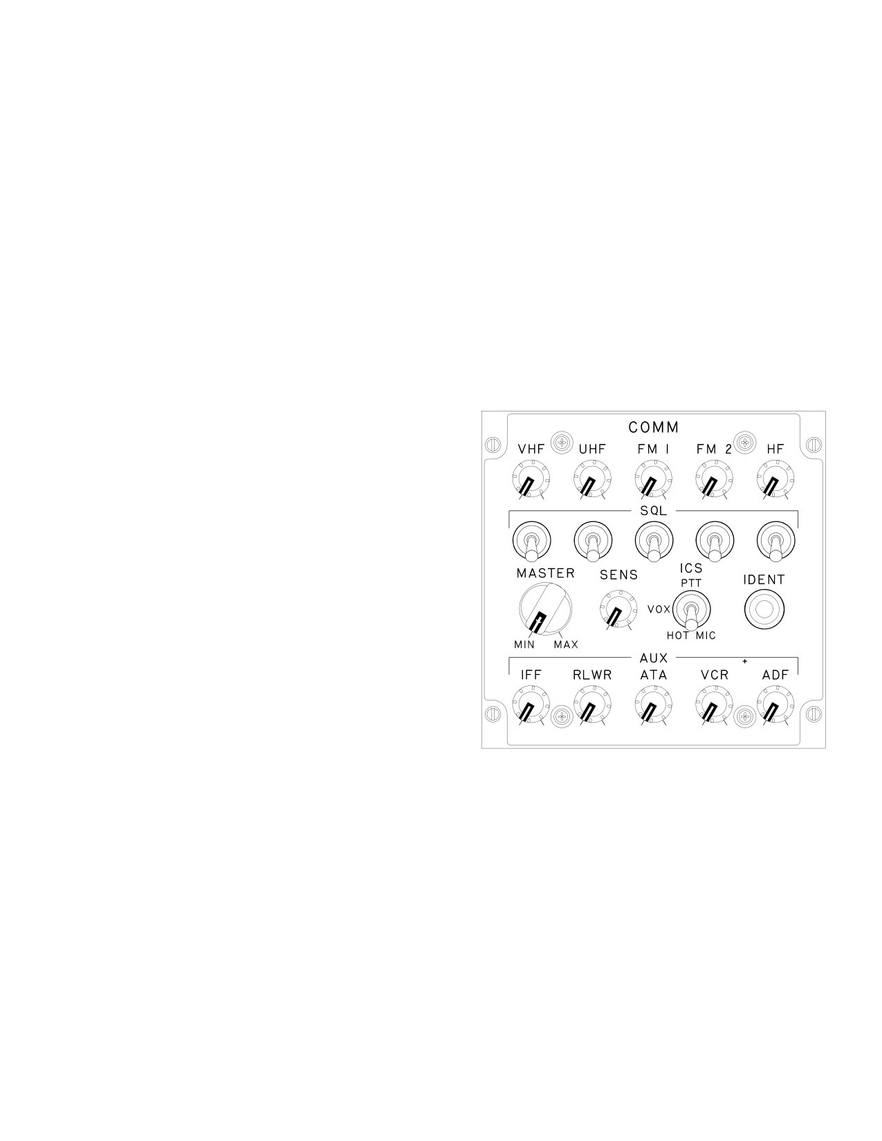
3.53Q COMMUNICATIONS (COMM) PANEL
2. The EUFD displays a left - pointing arrow symbol
in the second field for that crewstation’s RTS
There is a COMM panel (fig 3-62E) in each crewstation to
(transmit/receive) indicator. The opposite
provide volume control and other functions for the respec-
crewstation’s RTS indicator is displayed as a
tive crewstation. Following is a description of the COMM
right - pointing arrow symbol. Dots (no arrow) in-
panel controls:
dicate that the radio is enabled for monitoring
(receiving) only.
3. Radio identifier (VHF, UHF, FM1, FM2 or HF ).
ÑÑ
ÑÑ
Ñ
ÑÑ
ÑÑ
4. Squelch Off/On status (asterisk indicates
ÑÑ
ÑÑÑÑÑÑÑ
ÑÑ
squelch On).
ÑÑ ÑÑÑÑÑÑÑ ÑÑ
5. Currently tuned frequency/FH parameters.
• When the UHF radio is in Frequency Hopping
mode, the UHF frequency displayed on the EUFD
is an ’F’ followed by the net number. When in the
Training mode, the UHF frequency displayed on
ÑÑÑ
ÑÑ
the EUFD is a ’T’ followed by the training net
ÑÑÑ
ÑÑ
number.
ÑÑÑ
ÑÑ
• When SINCGARS is in Frequency Hopping mode,
the Active Hopset is displayed in the correspond-
ing EUFD FM Current Frequency location in the
form Fxxx, where xxx is the Hopset ID.
ÑÑ
ÑÑÑÑÑÑÑ
ÑÑ
ÑÑ
ÑÑÑÑÑÑÑ
ÑÑ
6. Call Sign (EUFD primary) currently assigned to
the currently tuned radio: MAN = manual tune;
LBA0072
GUARD = Guard tune
7. Cipher Off/On status and Crypto Net Variable
Figure 3-62E. Communications (COMM) Panel
(UHF, FM 1, FM 2, and HF only).
8. Guard (G) receiver Off/On (UHF only).
3.53Q.1 Volume Controls. The top row of five knobs
provide independent volume control for the respective ra-
9. IDM Net status, L = Longbow {AFAPD}, and T =
dios. Monitoring of the radios, VCR, and ADF audio can
Tacfire).
be disabled by pulling out the respective control knob
which removes the appropriate monitor status dot from
10. Standby (last tuned) frequency/FH parameters.
the EUFD, unless selected as the active transmitter.
11. Power status. IFM power status includes OFF,
LOW, NORM, HIGH. HF power status includes
3.53Q.2 Squelch (SQL) Switches. The SQL switches
LOW, MEDIUM, HIGH.
are momentary toggle switches that provide squelch on/
off capability. There is a SQL switch for each radio, lo-
12. Current time (Local or Zulu)).
cated directly below the corresponding volume control
13. HF radio status (Table 3-3B).
knob.
Use or disclosure of this information is subject to the restriction(s) on the title page of this document.
Change 3
3-66.9
TM 1-1520-251-10
3.53Q.3 MASTER Control. The MASTER control pro-
3.53R EMERGENCY PANEL
vides the capability to adjust the audio level (volume) of all
signals associated with the communication subsystem
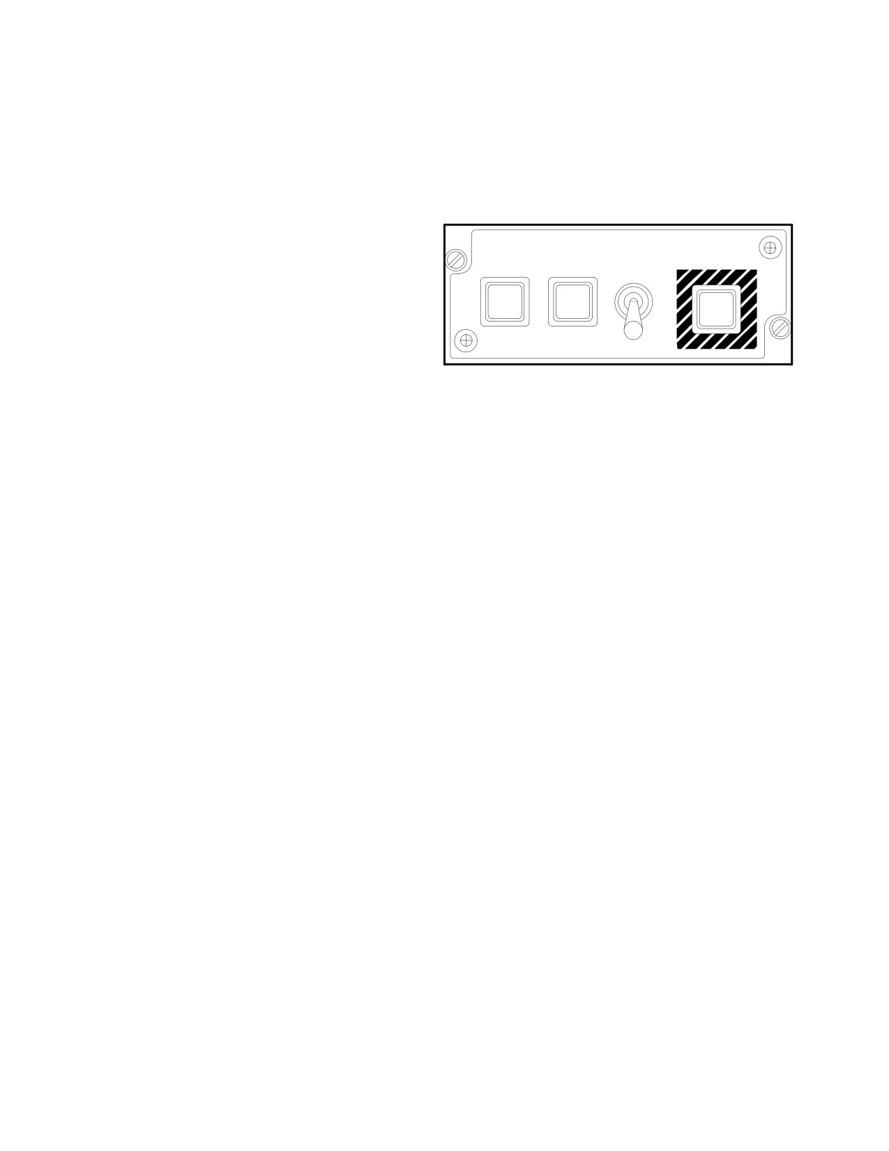
The EMERGENCY panel (fig 3-62F) communications
and controls the applicable crewstation helmet and wing
functions provides for tuning the UHF radio to the GUARD
connection volume levels.
frequency, selection of the transponder (XPNDR) emer-
gency mode, and zeroizing classified data.
3.53Q.4 Sensitivity (SENS) Control. The SENS con-
trol provides the capability to adjust the audio threshold
level when the ICS mode switch is in the VOX position.
EMERGENCY
EMERG
HYD
The system only transmits when voice level exceeds the
GUARD
XPNDR
ZEROIZE
threshold setting of the SENS adjustment. To increase
sensitivity rotate control clockwise.
ON
ON
ON
3.53Q.5 ICS Mode Switch. The ICS mode switch pro-
vides selection of the audio keying system for commu-
nication between crew stations. Following are the three
LBA2448
modes that can be selected with the ICS switch:
Figure 3-62F. EMERGENCY Panel
a. Push-To-Talk (PTT). The PTT position allows
communication only while the ICS PTT switch is being de-
pressed.
3.53R.1 GUARD Lighted Button. Pressing this button
tunes the UHF radio to its guard frequency, which is dis-
b. VOX. The VOX position allows communication
played on the EUFD, and causes the system to automati-
between crewmembers only when their voice levels ex-
cally select (RTS) the UHF radio. Pressing the GUARD
ceed the threshold level as set with the SENS control.
button again commands the system to swap the primary
and standby locations of the EUFD: 1) the guard frequen-
cy is swapped into the EUFD’s standby frequency loca-
c. HOT MIC. The HOT MIC position allows continu-
tion; and 2) the radio and/or preset - net data previously in
ous communication between crewmembers.
the standby location is swapped back into the EUFD’s pri-
mary location.
3.53Q.6 IDENT Switch. The IDENT switch allows the
transponder to be placed in IDENT mode. This switch per-
3.53R.2 XPNDR Lighted Button. Pressing this button
forms the same function as the IDENT option label located
sets a code of 7700 in mode 3/A. The XPNDR Mode 3/A
on the MPD XPNDR page.
button has to be moded ON and XPNDR MASTER button
can be in NORM or STBY prior to activating the XPNDR
3.53Q.7 AUX Controls
emergency button. The EUFD provides a status of 7700
EMER to indicate that emergency transponder mode has
a. Identification, Friend or Foe (IFF). The IFF
been selected. To exit the emergency transponder mode,
knob provides independent volume control of the IFF
press the XPNDR button again, which will extinguish the
MODE 4 audio.
light. After deactivation, the system does not reset any
codes until they are entered manually or with the Data
b. Radar/Laser Warning Receiver (RLWR). The
Transfer Cartridge (DTC).
RLWR knob provides independent volume control of the
RLWR audio.
3.53R.3 ZEROIZE Switch. The ZEROIZE switch is ac-
tioned by first pulling it up and out of the locked position,
c. Air - To - Air (ATA). This knob is not currently
next to the forward position, and then returning the switch
used.
to the locked or after position to complete the zeroization
process. Actioning the ZEROIZE switch zeroes-out the
d. Video Cassette Recorder (VCR). The VCR
following classified data:
knob provides independent volume control of the VCR
playback audio.
a. COMSEC variables
e. Automatic Direction Finder (ADF). The ADF
b. FM1 and FM2 Hopsets
knob provides independent volume control of the ADF au-
dio.
c. FM1 and FM2 lockout sets
Use or disclosure of this information is subject to the restriction(s) on the title page of this document.
3-66.10
Change 3
TM 1-1520-251-10
d. HF radio
3.53S CYCLIC GRIP COMMUNICATIONS CONTROLS
e. HQ1 WOD or HQ2 MWOD from radio, and SP
A three position ICS switch on the cyclic control grips pro-
Non - Volatile Memory (NVM)
vide the crew with ICS, PTT and RTS functionality.
f. All Signal Operating Instructions (SOI) tables/data
3.53T ICS/RADIO FOOT CONTROLS
in Data Processor (DP) NVM
g. Mode 4 (KIT-1C)
ICS/Radio foot controls are identical for both crew stations
and are located on the forward crew station deck. The ra-
h. IDM network parameters
dio PTT foot control is located on the left side of the crew
station. The ICS PTT foot control is located on the right
i. IDM team member indications in the IDM and DP
side of the crew station.
NVM
3.53U COMMUNICATION SUBSYSTEM DISPLAY
j. Tactical Situation Display (TSD) Waypoints, Tar-
FORMAT OVERVIEW
gets/Threats, and Control Measures
The Communication Subsystem controls and displays are
NOTE
accessed through the MPDs in each crew station. The
• Emergency zeroize does not erase clas-
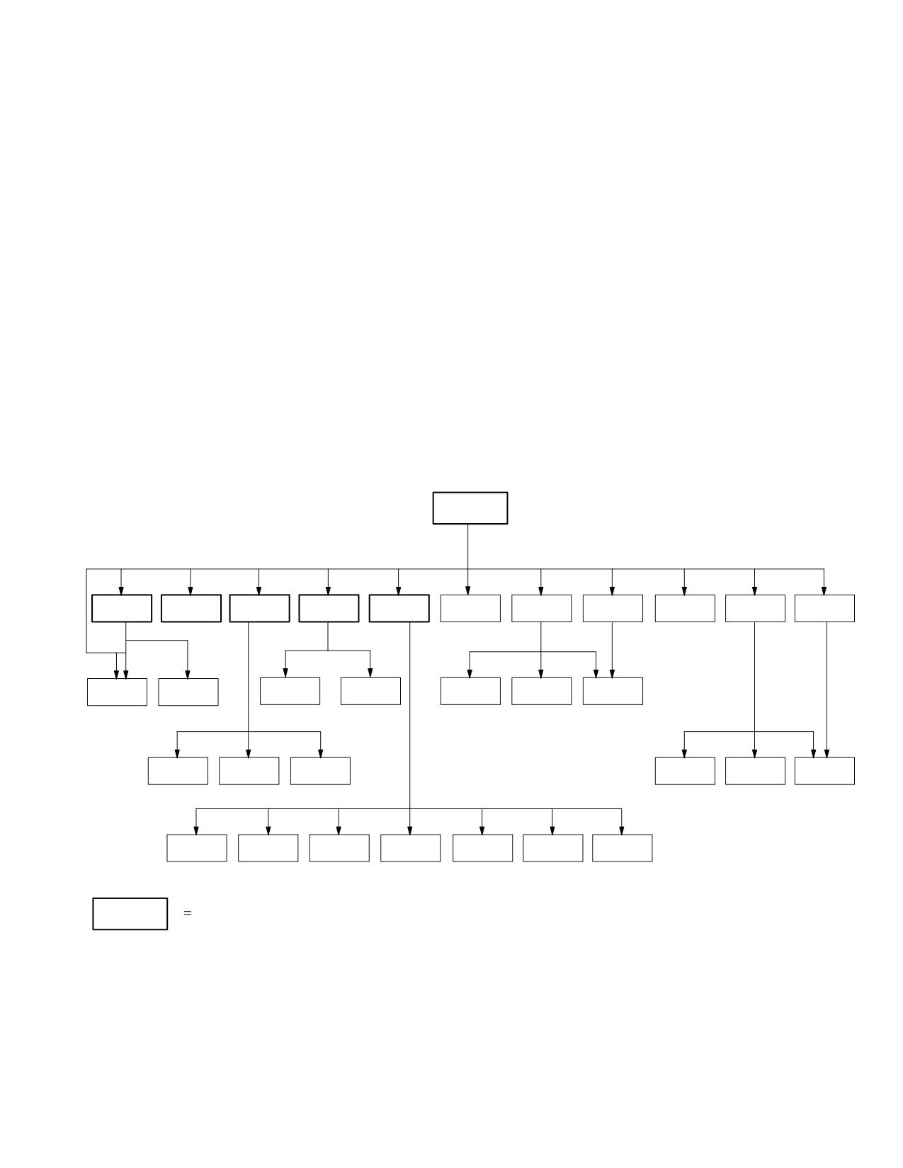
paging tree (fig 3-62G) illustrates the structure of the COM
sified data in the FCR and DTC
subsystem pages.
COM
PRESET
ORIG
MSG
MSG
SOI
XPNDR
UHF
FM
HF
MAN
NET
EDIT
ID
SEND
REC
PRESET
MBR
EXPND
ERF
SET
SUFFX
MODEM
DIR
DIR
FREE
CURRENT
WOD
FMT
SET
ATHS
TEXT
MISSION
SELF
NETS
NETS
CALL
PRESETS
SET
ZERO
ADDRESS
(ALE)
(ECCM)
ADDRESS
Available from MENU Page
LBA5067B
Figure 3-62G. COM Subsystem Paging Tree
3.53V COMMUNICATIONS PROTOCOL AND
3.53V.1 Originator ID. The unique digital identification of
NETWORKS
the ownship or a formal leadership role entity associated with
the ownship. Digital ID’s include: 1) LONGBOW and 2) TAC-
The following communications protocol and network ter-
FIRE.
minologies are used throughout this section:
Use or disclosure of this information is subject to the restriction(s) on the title page of this document.
Change 3
3-66.11
TM 1-1520-251-10
NOTE
An entity is any single platform, system,
leadership role position, staff role position,
etc. that has an assigned digital ID relation-
ship.
3.53V.2 Network. A functionally related group of mem-
bers that are assigned and configured with a common: 1)
radio type; 2) SC frequency, or HOPSET/ECCM ID; 3) call
sign; 4) crypto key, when required; 5) protocol, for digital
networks.
3.53V.3 Member. A member, or subscriber, is a single
member or station assigned to a network. Each digital
member entity is assigned a unique digital identification.
Digital ID’s include: 1) LONGBOW and 2) TACFIRE.
LBA5176
3.53V.4 Team Member. A team member is a network
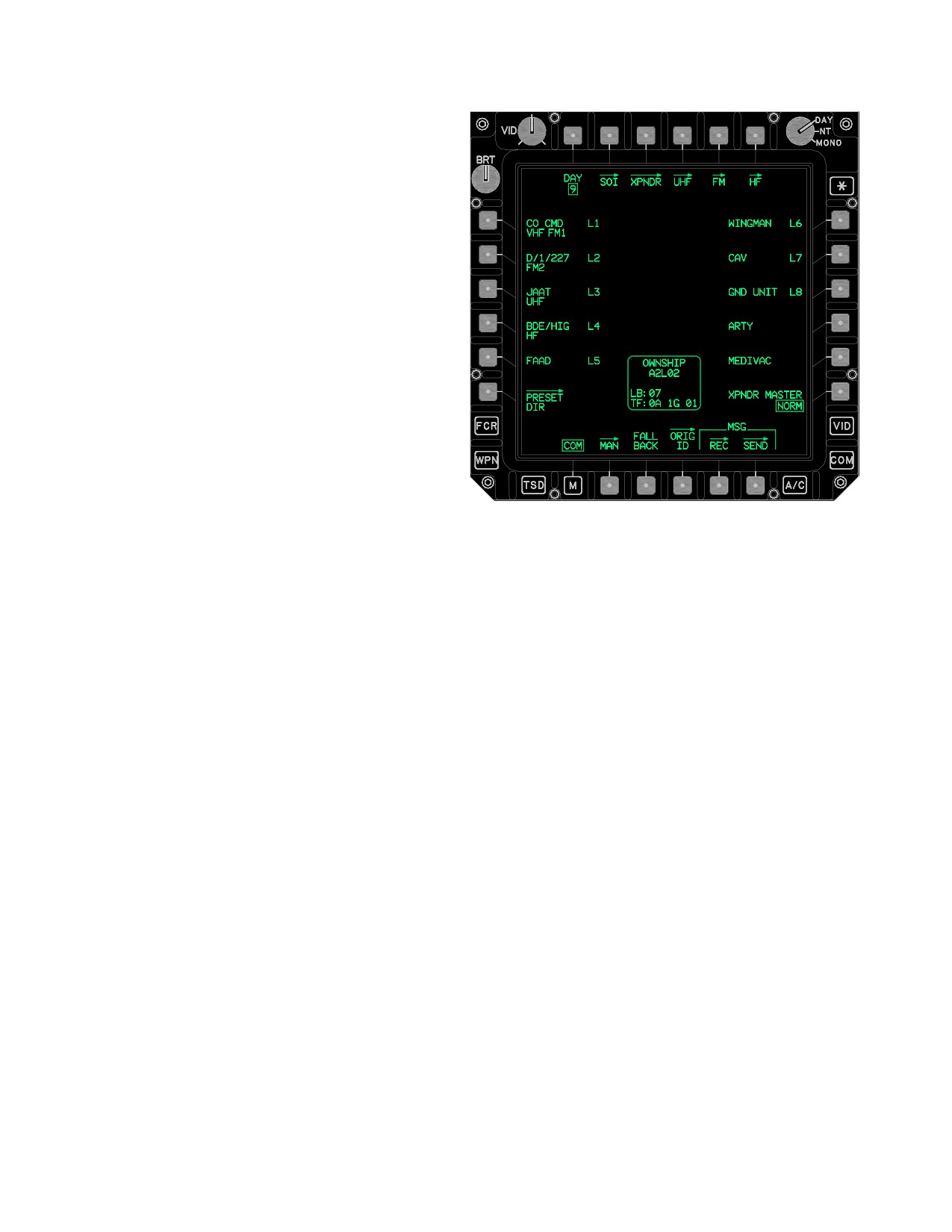
Figure 3-62H. COM Page
member designated to receive Longbow or Tacfire team
messages. Each digital network may contain up to 16
Buttons on the COM page are described below:
team members (including ownship).
• T1
DAY button
• T2
SOI button
• T3
XPNDR button
3.53V.5 Primary Member. A primary member is a net-
• T4
UHF button
work member designated to receive primary messages
from the TSD RPT page over a Longbow net. There are a
• T5
FM button
maximum of 8 primary members (including the ownship)
• T6
HF button
per digital network (1 - 10). A net member does not have to
• L1-L5
PRESET buttons
be a team member to be a primary member.
•
L6
PRESET DIR button
• R1-R5
PRESET buttons
• R6
XPNDR MASTER button
3.53W COMMUNICATIONS (COM) PAGE
• B2
MAN button
• B3
FALL BACK button
The COM page (fig 3-62H) is used to manage up to eight
• B4
ORIG ID button
preset - networks. Longbow and TACFIRE protocols may
• B5
MSG REC button
only be used with preset - nets one through eight (1-8).
• B5
MSG SEND button
Any of the eight COM page preset - nets may be replaced
through using the PRESET DIRectory’s preset replace
3.53W.1 DAY Button. The DAY button provides the ca-
function. The PRESET DIR is a database capable of con-
pability to toggle between the two SOI days of the SOI
taining up to 60 Longbow, TACFIRE, and voice - only pre-
data that is displayed within the communications subsys-
set database items with up to 15 members each. Select-
tem. The two SOI days are numbers with a range of 1- 10.
ing the COM subsystem button or the COM page button
When the operator actions the DAY button the Display
from the MENU page displays the COM page. Various
Processor updates the SOI data to the alternate day. Se-
communication subsystem status windows and control
lecting the button again will toggle the data back to the
selections are provided by bezel buttons located along the
original day. The SOI day number is uploaded to the Dis-
edges of the MPD. The paging options at the top of the
play Processor from the DTC as part of the Presets
page provide access to subsystem functional pages.
upload.
Use or disclosure of this information is subject to the restriction(s) on the title page of this document.
3-66.12
Change 3
TM 1-1520-251-10
3.53W.2 SOI Page Button. The SOI button displays
NOTE
the SOI page.
The pilot and CPG floor, push to talk
•
switches are inoperative when operating
the CIU in the Fall Back mode.
3.53W.3 XPNDR Page Button. The XPNDR button
displays the XPNDR page.
• Operating in the Fall Back mode requires
a TEMPEST microphone to communi-
cate on either intercom or the the radios.
3.53W.4 UHF Page Button. The UHF button displays
the UHF page.
The following occurs when Fall Back is initiated:
• Pilot is RTS to the UHF radio.
3.53W.5 FM Page Button. The FM page button dis-
plays the FM page.
• UHF radio will go secure if a KY- 58 is installed and
turned ON. If the FILL position selected is not
loaded with a CNV, only plain radio reception is
3.53W.6 HF Page Button. The HF page button dis-
available. Attempting to transmit will result in a
plays the HF page.
steady tone.
• CPG is RTS to the VHF radio.
3.53W.7 PRESET Buttons. The PRESET (1-10) but-
• Pilot and CPG radio monitor levels are defaulted
tons provide the capability to tune the VHF, UHF, FM 1,
to a fixed level.
FM 2, and HF radios. The VHF, UHF, FM 1, and FM 2 but-
tons also provide configuration control for the IDM chan-
• ICS communication between the Pilot and CPG is
nels. The PRESET buttons are not selected upon display
moded to Hot MIC (TEMPEST MIC Only).
of the COM page. The PRESET buttons each contain two
lines of text information. The first line contains the Unit ID,
3.53W.12 MSG REC Page Button. The MSG REC but-
IDM net protocol, and IDM net number. The second line
ton displays the message receive (MSG REC) page.
contains the Radio Status. Presets 1-8 support “L” digital
3.53W.13 MSG SEND Page Button. The MSG SEND
net configurations.
button displays the MSG SEND page.
3.53W.14 OWNSHIP Status Window. The OWNSHIP
3.53W.8 PRESET DIR Button. The PRESET DIR page
Status window (fig 3-62H) displays the ownship’s global
button displays the PRESET DIR page. See paragraph
COM and IDM data. Before flight reference permits the
3A.32.
crew to check the OWNSHIP’s IDM-COM data at one
single top level location without the requirement to page
through the ORIG ID Page options following a DTU Load
3.53W.9 XPNDR MASTER Button. The XPNDR MAS-
with the IDM in OPER. The OWNSHIP Status window in-
TER button toggles between Standby (STBY) and Normal
cludes the following data fields:
(NORM) modes.
LB (Longbow) Digital ID
•
• TF (TACFIRE) Digital ID, Team ID, and Broadcast
3.53W.10 MAN Page Button. The MAN button dis-
ID
plays the MAN page.
3.53W.15 ORIG ID Page Button. The ORIG ID page
button displays the ORIG ID page
(paragraph
3A.253.53X).
3.53W.11 FALL BACK Button. The FALL BACK but-
ton is selected upon a CIU failure as indicated by the
3.53X ORIG ID Page.
EUFD advisory “GO FALLBACK”. Selection of the FALL
BACK button will prompt for a YES or NO confirmation to
initiate Fall Back. However, the FALL BACK button will
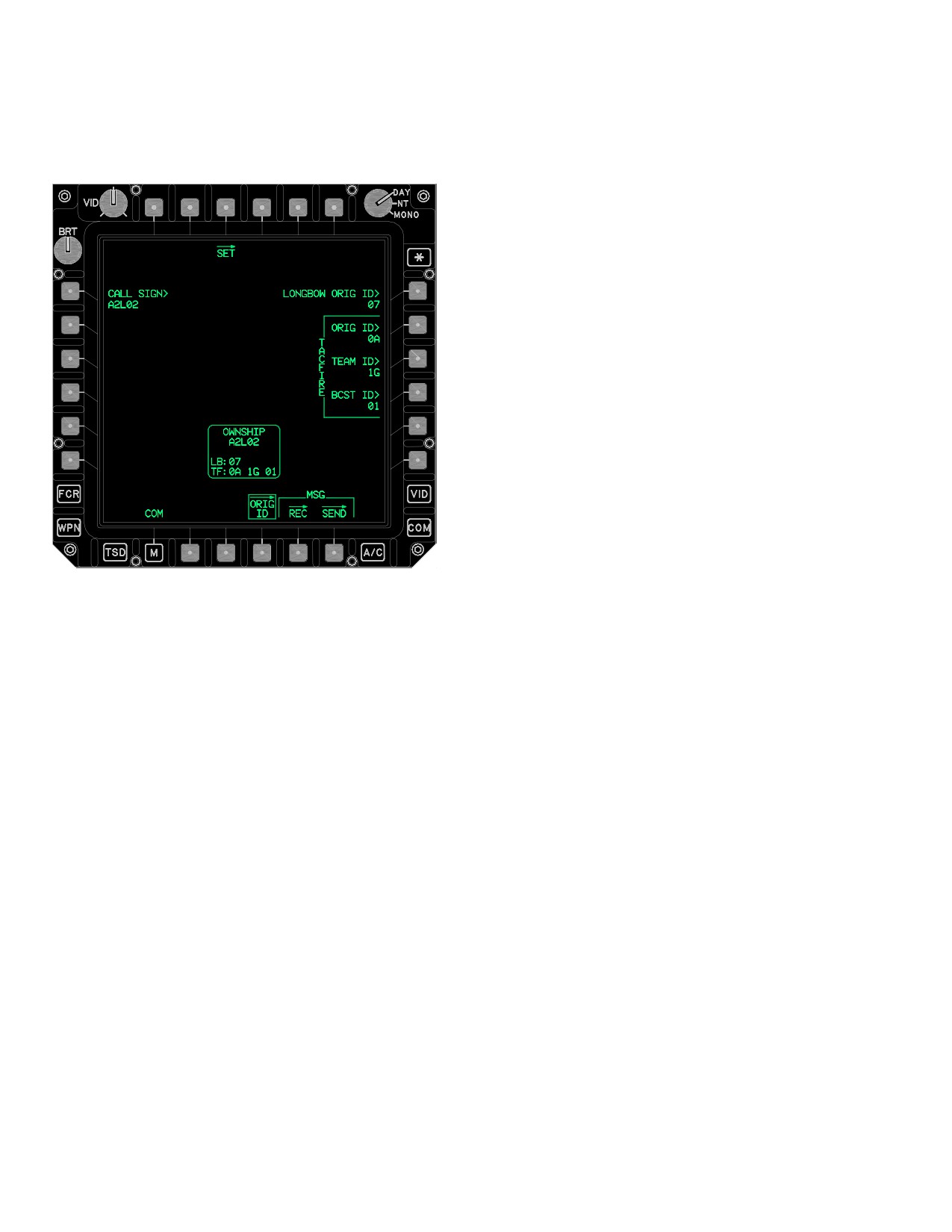
The ORIG ID page (fig 3-62I) is accessed by selecting the
not prompt for confirmation to exit Fall Back. Once Fall
ORIG ID page button located on the COM page. The
Back is initiated the EUFD advisory will change to “FALL-
ORIG ID page provides a means of editing the originator/
BACK”.
ownship’s callsign and digital identification for the IDM
Use or disclosure of this information is subject to the restriction(s) on the title page of this document.
Change 4
3-66.13
TM 1-1520-251-10
protocols. Upon display of the page, the DIGITAL ID
the sender’s ID when transmitting Longbow messages.
LONGBOW/TACFIRE button is selected.
The keyboard label displays LONGBOW ID and accepts a
one or two - character input between 0 - 39, A - Z, 1A - 1Z,
2A - 2Z, or 3A - 3I.
3.53X.3 TACFIRE ORIG ID Button. The TACFIRE
ORIG ID data entry button permits editing the IDM origina-
tor ID for the Tacfire protocol. This ID is used as the send-
er’s ID when transmitting Tacfire messages. The key-
board label displays TACFIRE ID and accepts a one or
two character input between 0 - 39, A - Z, 1A - 1Z, 2A - 2Z,
or 3A - 3I.
NOTE
The TACFIRE TEAM ID has to initially be
entered as a member in at least one TAC-
FIRE preset-net prior to the TACFIRE
TEAM ID being entered through the ORIG
ID page.
3.53X.4 TACFIRE TEAM ID Button. The TACFIRE
TEAM ID data entry button permits editing the originator’s
LBA5177
Tacfire Team ID. This ID represents the TACFIRE team
address associated with ownship’s IDM. The keyboard la-
bel displays TEAM ID and accepts a one or two character
Figure
3-62I.
ORIG ID Page LONGBOW/TACFIRE
input between 0 - 39, A - Z, 1A - 1Z, 2A - 2Z, or 3A - 3I.
Buttons on the ORIG ID page, LONGBOW/TACFIRE se-
NOTE
lected:
• L1
CALL SIGN button
The TACFIRE BCST ID has to initially be
entered as a member in at least one TAC-
• R1
LONGBOW ORIG ID button
FIRE preset-net prior to the TACFIRE
• R2
TACFIRE ORIG ID button
TEAM ID being entered through the ORIG
ID page.
• R3
TACFIRE TEAM ID button
• R4
TACFIRE BCST ID button
3.53X.5 TACFIRE BCST ID Button. The TACFIRE
BCST ID data entry button permits editing the IDM’s
• B4
ORIG ID button
Broadcast ID for the Tacfire protocol. This ID represents
• B5
MSG REC button
the TACFIRE broadcast address associated with the origi-
nator’s aircraft. The keyboard label displays BROAD-
• B6
MSG SEND button
CAST ID and accepts a one or two character input be-
3.53X.1 CALL SIGN Button. The originator’s CALL
tween 0 - 39, A - Z, 1A - 1Z, 2A - 2Z, or 3A - 3I.
SIGN data entry button permits editing, and creation of,
the originator’s call sign as displayed in the OWNSHIP
3.53Y COM PAGE - PRESET SELECTED
Status window.
3.53X.2 LONGBOW ORIG ID Button. The LONG-
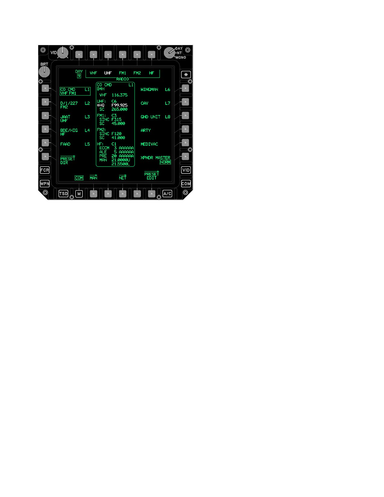
The COM page (fig 3-62J) preset status window displays
BOW ORIG ID data entry button permits editing the IDM
the data associated with the preset that is currently se-
Originator ID for the Longbow protocol. This ID is used as
lected.
Use or disclosure of this information is subject to the restriction(s) on the title page of this document.
3-66.14
Change 3
TM 1-1520-251-10
3.53Y.1 NET Page Button. The NET button displays
the net member page. See paragraph 3A.33.
3.53Y.2 PRESET EDIT Page Button. The PRESET
EDIT button displays the preset edit page. See paragraph
3.53N.
3.53Y.3 COM PRESET Status Window. The COM
PRESET status window data is displayed in the following
field order:
• Unit ID
• Call Sign
• DM Type and IDM Preset - Net Number
• VHF Frequency
• UHF CNV status
• UHF HQ Net number
• UHF Single Channel Frequency
LBA5178
• FM1 CNV status
Figure 3-62J. COM Page (PRESET Selected)
•
FM1 SINC net number
The following unique buttons are displayed on the COM
• FM1 Single Channel Frequency
page when a preset is selected:
• FM2 CNV status
• T2
RADIO VHF button
• FM2 SINC HOPSET number
• T3
RADIO UHF button
• FM2 CNV status
• T4
RADIO FM1 button
• HF CNV status
• T5
RADIO FM2 button
• T6
RADIO HF button
• HF ECCM
• B4
NET page button
• HF ALE
• B6
PRESET EDIT page button
• HF PRE
NOTE
• HF MAN (Upper/Lower)
Each specific RADIO T2-T6 buttons are
displayed anytime the selected preset con-
The Primary frequency is displayed in white and desig-
tains valid data for the radio type.
nated by a white arrow.
Use or disclosure of this information is subject to the restriction(s) on the title page of this document.
Change 3
3-66.15
TM 1-1520-251-10
3.53Z MAN PAGE
• R4
HF XMIT EMISSION (USB/LSB) button
• B3
VHF WB/NB antenna button
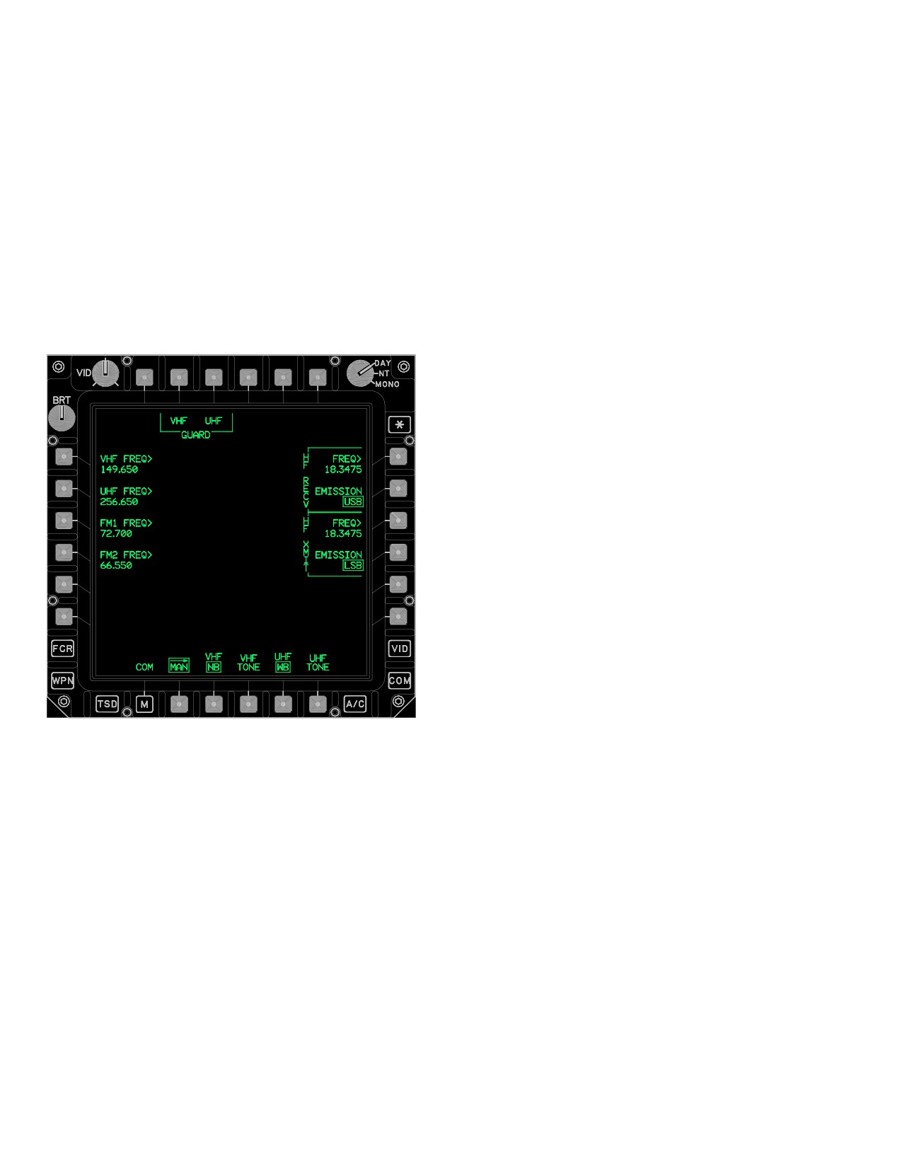
The MAN page (fig 3-62K) provides the following capabili-
• B4
VHF TONE button
ties:
• B5
UHF WB/NB antenna button
• Tune the VHF and/or UHF guard frequency
• B5
UHF TONE button
• Manually tune the VHF, UHF, FM1, FM2, and HF
radios through frequency data input
3.53Z.1 VHF GUARD Button. The VHF GUARD but-
ton provides the capability to rapidly tune the VHF radio to
• Select antenna bandwidths for the UHF and VHF
the guard frequency.
radios
• UHF/VHF radio test tone button access
3.53Z.2 UHF GUARD Button. The UHF GUARD but-
ton provides the capability to rapidly tune the UHF radio to
the guard frequency.
3.53Z.3 VHF FREQ Button. The VHF FREQ data entry
button provides the capability to manually tune the VHF
radio (108.000 through 151.975 MHz at 0.025 spacing)
using the KU. The KU label display is VHF FREQ and the
selection of the KU’s ENTER button commands the VHF
radio to tune to the manually set frequency.
3.53Z.4
UHF FREQ Button. The UHF FREQ data
entry button provides the capability to manually tune the
UHF radio (225.000 through 399.975 MHz at 0.025 spac-
ing steps) using the KU. The KU label display is UHF
FREQ and the selection of the KU’s ENTER button com-
mands the UHF radio to tune to the manually set frequen-
cy.
3.53Z.5 FM1 FREQ Button. The FM1 FREQ data entry
button provides the capability to manually tune the FM1
radio (30.000 through 87.975MHz at 0.025 MHz steps)
LBA5090
using the KU. The KU label display is FM1 FREQ and the
selection of the KU’s ENTER button commands the FM1
Figure
3-62K.
MAN Page
radio to tune to the manually set frequency.
3.53Z.6 FM2 FREQ Button. The FM2 FREQ data entry
The MAN page contains the following unique buttons:
button provides the capability to manually tune the FM1
radio (30.000 through 87.975MHz at 0.025 MHz steps)
• T2
VHF GUARD button
using the KU. The KU label display is FM2 FREQ and the
• T3
UHF GUARD button
selection of the KU’s ENTER button commands the FM2
• L1
VHF FREQ button
radio to tune to the manually set frequency.
• L2
UHF FREQ button
3.53Z.7 HF RECV FREQ Button. The HF RECV FREQ
• L3
FM1 FREQ button
data entry button provides the capability to manually tune
• L4
FM2 FREQ button
the HF radio receive frequency (2.0000 through 29.9999
• R1
HF RECV FREQ button
MHZ at 0.1 kHz steps). The KU label display is HF RECV
FREQ and the selection of the KU’s ENTER button com-
• R2
HF RECV EMISSION (USB/LSB) button
mands the HF radio to tune to the manually set HF RECV
• R3
HF XMIT FREQ button
frequency.
Use or disclosure of this information is subject to the restriction(s) on the title page of this document.
3-66.16
Change 3
TM 1-1520-251-10
3.53Z.8 HF RECV EMISSION Button. The HF RECV
3.53Z.13 UHF WB/NB Button. UHF WB/NB button
EMISSION button provides the capability to select the HF
provides the capability to toggle between the WB (Wide
radio receive emission mode for the manual receive fre-
Bandwidth, ±35KHz deviation from the channel frequency
quency. The button provides the following HF RECV
allowing more noise or crosstalk from frequencies within
EMISSION multi - state options:
.025MHz ) and NB (Narrow Bandwidth allows ±12KHz
deviation from the channel frequency) modes. The default
• AME to select Amplitude Modulation Equivalent.
state upon power - up for the VHF bandwidth is narrow.
• CW to select Continuous Wave.
The UHF bandwidth is automatically set to WB option
when the UHF mode is set to the UHF CIPHER and to NB
• LSB to select Lower Sideband.
when the UHF mode is set to the UHF PLAIN. Upon pow-
• USB to select Upper Sideband.
er - up, the UHF bandwidth is determined by the state of
the UHF KY - 58.
Upper Sideband is the default receive emission mode
3.53Z.14 UHF TONE Button. The UHF TONE momen-
upon power - up. Changing the receive emission mode of
tary button provides the capability to enable the UHF Ra-
the HF radio automatically changes the transmit emission
dio (ARC - 164) Test Tone. Selection of the UHF TONE
mode to the same value.
button transmits an over the air radio generated tone. The
tone is used for test and problem isolation.
3.53Z.9 HF XMIT FREQ Button. The HF XMIT FREQ
data entry button provides the capability to manually tune
3.53AA COM PAGE - PRESET AND RADIO
the HF radio receive frequency (2.0000 through 29.9999
SELECTED
MHZ at 0.1 kHz steps). The KU label display is HF XMIT
FREQ and the selection of the KU’s ENTER button com-
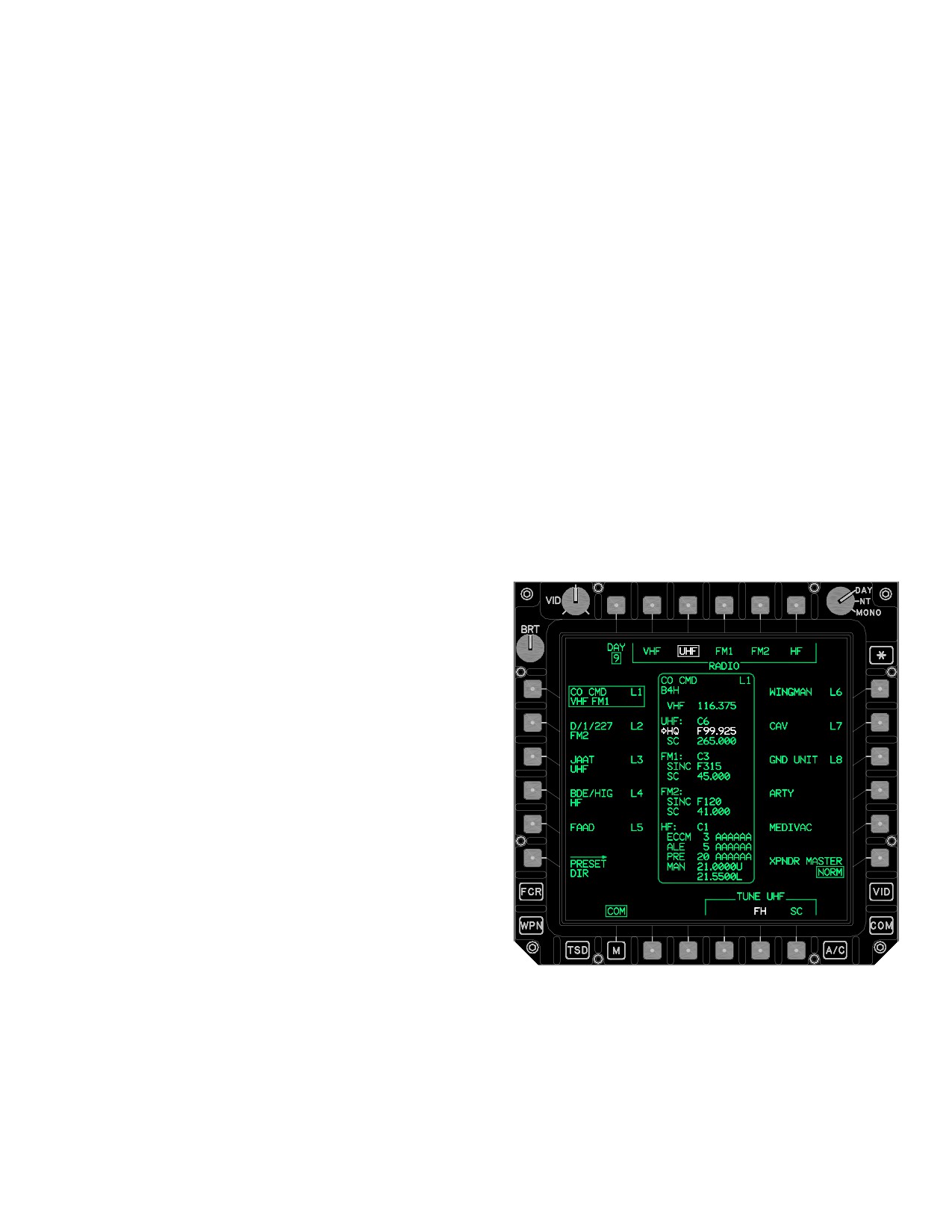
The COM page (fig 3-62L) specific TUNE VHF, FM1, FM2,
mands the HF radio to tune to the manually set HF XMIT
or HF button options are displayed following the selection
frequency.
of a RADIO option button.
3.53Z.10 HF XMIT EMISSION Button. The HF XMIT
EMISSION button provides the capability to select the HF
radio receive emission mode for the manual receive fre-
quency. The button provides the following HF XMIT EMIS-
SION multi - state options:
• AME to select Amplitude Modulation Equivalent.
• CW to select Continuous Wave.
• LSB to select Lower Sideband.
• USB to select Upper Sideband.
Upper Sideband is the default receive emission mode
upon power - up. Changing the receive emission mode of
the HF radio automatically changes the transmit emission
mode to the same value.
3.53Z.11 VHF WB/NB Button. VHF WB/NB button
provides the capability to toggle between the WB (Wide
Bandwidth, 18KHz) and NB (Narrow Bandwidth, 9.5KHz)
modes. The default state upon power-up for the VHF
bandwidth is narrow.
3.53Z.12 VHF TONE Button. The VHF TONE momen-
tary button provides the capability to enable the VHF Ra-
LBA5179
dio (ARC - 186) Test Tone. Selection of the VHF TONE
button transmits an over the air radio generated tone. The
Figure
3-62L.
COM Page Preset and Radio UHF
tone is used for test and problem isolation.
Selected
Use or disclosure of this information is subject to the restriction(s) on the title page of this document.
Change 3
3-66.17
TM 1-1520-251-10
The COM page with preset selected contains the follow-
• B6
TUNE VHF SC button
ing unique buttons:
Selecting the TUNE VHF SC button tunes the VHF radio
• T2
RADIO VHF button
to the frequency displayed in the VHF SC status field of
• T3
RADIO UHF button
the PRESET STATUS window.
• T4
RADIO FM1 button
3.53AA.2 PRESET RADIO UHF Button. The selection
• T5
RADIO FM2 button
of the PRESET RADIO UHF button will command the dis-
• T6
RADIO HF button
play of the TUNE UHF button options.
NOTE
•
B4
TUNE UHF FH button
The FM radios can take as long as 10.0 sec-
• B6
TUNE UHF SC button
onds to completely tune/configure to a COM
preset. the FM radios are available for voice
a. TUNE UHF FH Button. Selecting the TUNE UHF
transmission within 2.0 seconds of tuning
FH button tunes the UHF radio to the HQ NET ID as dis-
but the transmissions may be broken.
played in the UHF HQ status field of the PRESET STA-
TUS window.
a. TUNE RADIO Command IDM - RADIO Configu-
ration Updates. When a VHF, UHF, FM1, or FM2 TUNE
RADIO button assigned to an IDM preset - net is selected
b. TUNE UHF SC Button. Selecting the TUNE UHF
the following radio and IDM processes occur:
SC button tunes the UHF radio to the frequency displayed
in the UHF SC status field of the PRESET STATUS win-
• The radio will tune - configure
dow.
• The radio channel in the IDM will be configured
when the preset has an IDM protocol assigned
3.30AA.3 PRESET RADIO FM1 or FM2 Button. The
• The Crypto in the KY will be configured if the preset
selection of the PRESET RADIO FM1 or FM2 button will
has a Crypto Net Variable displayed
command the display of the TUNE FM1 or FM2 button op-
tions.
b. TUNE RADIO Command EUFD Radio Status
Line Update. When any one of the TUNE RADIO option
• B4
TUNE FM1 or FM2 FH button
buttons is selected, the EUFD’s preexisting primary radio
• B5
TUNE FM1 or FM2 FH/M button
status line is moved to the EUFD’s standby area and the
• B6
TUNE FM1 or FM2 SC button
EUFD primary status is updated with the applicable PRE-
SET STATUS windows:
a. TUNE FM1 or FM2 FH Button. Selecting the
• Call Sign
TUNE FM1 or FM2 FH button tunes the specific FM radio
to the SINC FH using the NET ID displayed in the FM1 or
• Frequency
FM2 SINC status field of the PRESET STATUS window.
• Frequency - Hop/ECCM
• IDM Protocol
b. TUNE FM1 or FM2 FH/M Button. Selecting the
TUNE FM1 or FM2 FHM button tunes the specific FM ra-
• Crypto Status Fields
dio to the SINC FH/M mode using the NET ID that is dis-
played in the FM1 or FM2 SINC status field of the PRE-
c. TUNE RADIO Command PRESET Button Up-
SET STATUS window. The FH/M tune makes the aircraft
date. When any one of the TUNE RADIO option buttons
the master of the SINCGARS NET.
is selected, the radio tuned will be displayed in the second
line of the selected PRESET button.
c. TUNE FM1 or FM2 SC Button. Selecting the
3.53AA.1 PRESET RADIO VHF Button. The selection
TUNE FM1 or FM2 SC button tunes the specific FM radio
of the PRESET RADIO VHF button will command the dis-
to the frequency displayed in the FM1 (or FM2) SC status
play of the TUNE VHF option button.
field of the PRESET STATUS window.
Use or disclosure of this information is subject to the restriction(s) on the title page of this document.
3-66.18
Change 3
TM 1-1520-251-10
3.53AA.4 PRESET RADIO HF Button. The selection
of the PRESET RADIO HF button will command the dis-
play of the TUNE HF button options.
• B3
TUNE HF PRE button
• B4
TUNE HF ALE button
• B5
TUNE HF ECCM button
• B6
TUNE HF SC button
NOTE
An IDM preset - net tuned to a HF RADIO
TUNE button option will change that preset -
net to voice only.
a. TUNE HF PRE Button. Selecting the TUNE HF
PRE button tunes the HF radio to preset 1-20 as displayed
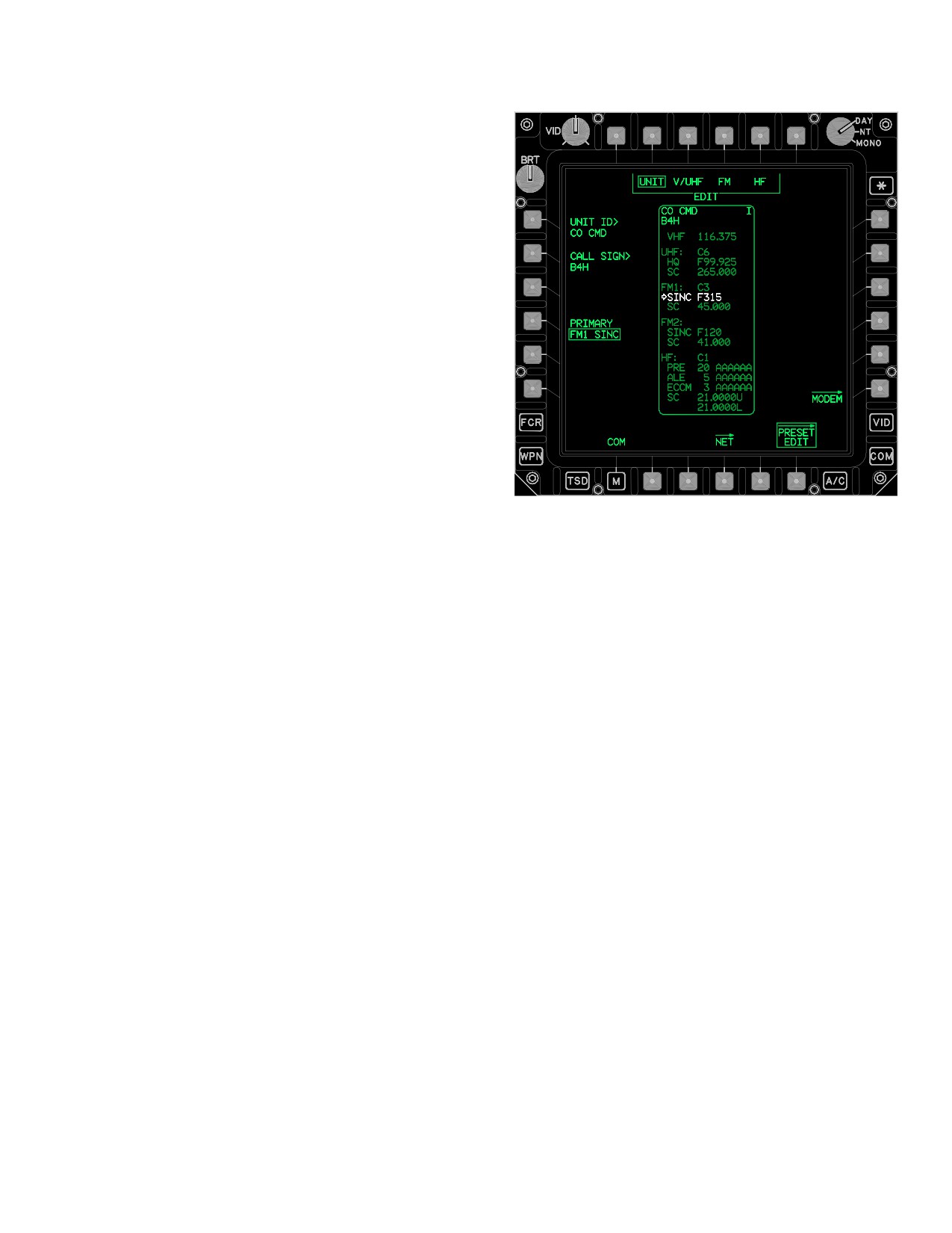
LBA5092
in the HF PRE status field of the PRESET STATUS win-
dow.
Figure 3-62M. PRESET EDIT Page (UNIT Selected)
b. TUNE HF ALE Button. Selecting the TUNE HF
The PRESET EDIT page contains the following unique
ALE button tunes the HF radio to the HF ALE Channel
buttons when the EDIT grouped option is UNIT:
(1-5) that is displayed in the HF ALE Status Field of the
PRESET STATUS window.
• T2 - T5
EDIT buttons
• L1
EDIT UNIT ID button
• L2
EDIT CALL SIGN button
c. TUNE HF ECCM Button. Selecting the TUNE
HF ECCM button tunes the HF radio to the HF ECCM Net
• L4
EDIT PRIMARY RADIO/MODE button
displayed in the HF ECCM Status Field of the PRESET
• R6
MODEM page button
STATUS window.
3.53AB.1 EDIT Buttons. The EDIT buttons provide the
capability to select a specific element of a preset’s COM
d. TUNE HF SC Button. Selecting the TUNE HF
data to edit.
SC button tunes the HF radio to the HF SC frequencies for
both the upper (U) and lower (L) sidebands as displayed
3.53AB.2 EDIT UNIT ID Button. The EDIT UNIT ID
in the HF SC Status Field of the PRESET STATUS win-
button changes the preset Unit ID.
dow.
3.53AB.3 EDIT CALL SIGN Button. The EDIT CALL
SIGN button changes the preset call sign.
3.53AB PRESET EDIT PAGE
3.53AB.4 EDIT PRIMARY RADIO Button. The EDIT
PRIMARY RADIO button provides the capability to
The PRESET EDIT page (fig 3-62M) provides the capabil-
change the radio-frequency/radio-mode association of
ity to modify the currently selected preset as displayed in
the Primary Radio indicator arrow (i.e. non - solid arrow) in
the PRESET STATUS window. Along with the Unit ID,
the PRESET STATUS window.
those items currently displayed for edit are displayed in
full intensity in the PRESET STATUS window, as opposed
3.53AB.5 MODEM Page Button. The MODEM button
to partial intensity.
displays the MODEM page. See paragraph 3A.313.53AC.
Use or disclosure of this information is subject to the restriction(s) on the title page of this document.
Change 3
3-66.19
TM 1-1520-251-10
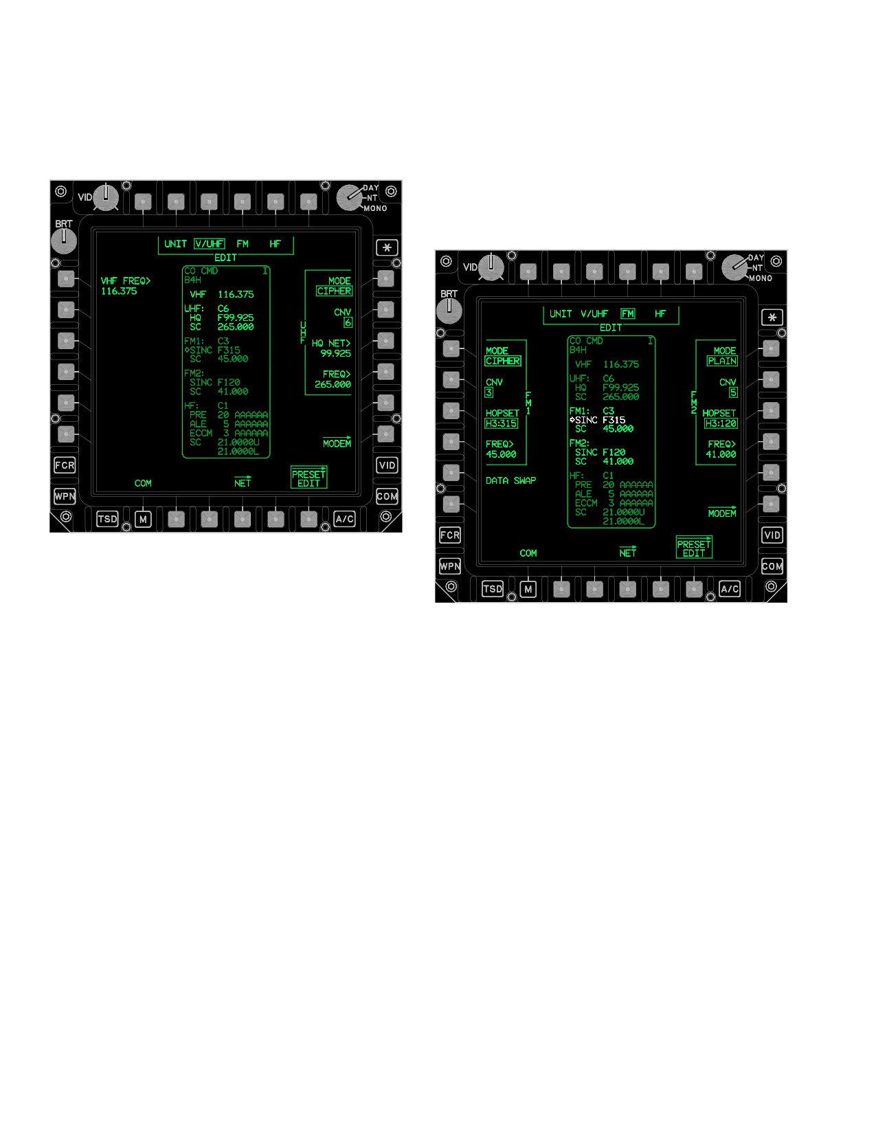
3.53AB.6 PRESET EDIT Page Button. The PRESET
3.53AB.10 EDIT HQ NET Button. The EDIT HQ NET
EDIT page button displays the PRESET EDIT page (fig
button changes the HAVEQUICK net number of the preset
3-62N).
in the range of 00.000 through 99.975.
3.53AB.11 EDIT UHF FREQ Button. The EDIT UHF
FREQ button changes the UHF element of the preset to a
frequency in the range of 225.000 through 399.985 MHz
in increments of 5 KHz.
LBA5093
Figure 3-62N. PRESET EDIT Page (V/UHF Selected)
LBA5094
The PRESET EDIT page contains the following unique
buttons when the EDIT grouped option is V/UHF:
Figure 3-62O. PRESET EDIT Page (FM Selected)
• L1
EDIT VHF FREQ button
NOTE
• R1
EDIT UHF MODE button
The PRESET EDIT FM selected page but-
• R2
UHF CNV selection button
tons (fig 3-62O) for FM1 and FM2 are func-
• R3
EDIT HQ NET button
tionally identical and the definitions below
apply to both radios.
• R4
EDIT UHF FREQ button
• R6
MODEM button
3.53AB.12 EDIT FM1/FM2 MODE Button. The EDIT
3.53AB.7 EDIT VHF FREQ Button. The EDIT VHF
FM 1/FM2 MODE button provides the capability to change
FREQ button changes the VHF element of the preset to a
the UHF Crypto Mode by toggling between Plain or Cipher
frequency in the range of 108.000 through 155.995, in in-
mode for the selected preset.
crements of 5 KHz (except for invalid 8.33 KHz channels).
3.53AB.13 EDIT FM1/FM2 CNV Button. The EDIT
3.53AB.8 EDIT UHF MODE Button. The EDIT UHF
FM1/FM2 CNV button allows changing the Crypto Net
MODE button provides the capability to change the UHF
Variable for the selected preset from 1-6.
Crypto Mode by toggling between Plain or Cipher mode
for the selected preset.
3.53AB.14 EDIT FM1/FM2 HOPSET Button. The
3.53AB.9 EDIT UHF CNV Button. The EDIT UHF CNV
HOPSET button provides six HOPSET button options.
button allows changing the Crypto Net Variable, for the se-
The hopset selected determines the radio FH characteris-
lected preset, from 1-6.
tics (hopping rate, frequencies and frequency order).
Use or disclosure of this information is subject to the restriction(s) on the title page of this document.
3-66.20
Change 3
TM 1-1520-251-10
3.53AB.15 EDIT FM1/FM2 FREQ Button. The EDIT
3.53AB.19 EDIT HF PRESET CHAN Button. The
FM1/FM2 FREQ button changes the FM1/FM2 for the se-
EDIT HF PRESET CHAN button changes the HF Preset
lected preset to a frequency in the range of 30.000
channel number of the preset in the range of 1-20.
through 87.995, in increments of 5 KHz.
3.53AB.20 EDIT HF ALE NET Button. The EDIT HF
3.53AB.16 EDIT FM1/FM2 DATA SWAP Button. The
ALE NET button changes the HF ALE net number of the
EDIT FM1/FM2 DATA SWAP button exchanges the FM1
preset in the range of 1-20.
and FM2 data displayed on the PRESET EDIT FM se-
lected page.
3.53AB.21 EDIT HF ECCM NET Button. The EDIT HF
ECCM NET button changes the HF ECCM net number of
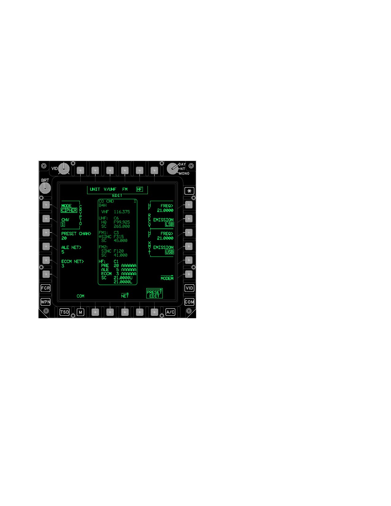
3.53AB.17 EDIT HF CRYPTO MODE Button. The
the preset in the range of 1-12.
EDIT HF CRYPTO MODE button (fig 3-62P) provides the
capability to change the HF Crypto Mode by toggling be-
3.53AB.22 EDIT HF RECV FREQ Button. The EDIT
tween Plain or Cipher mode for the selected preset.
HF RECV FREQ button changes the HF manual receive
frequency of the preset in the range of 2.0000 through
29.9999 MHz, in increments of 100 Hz.
3.53AB.23 EDIT HF RECV EMISSION Button. The
EDIT HF RECV EMISSION button changes the HF manu-
al receive emission of the preset between LSB (Lower
Side Band), USB (Upper Side Band), CW (Continuous
Wave), or AME (Amplitude Modulation Equivalent).
3.53AB.24 EDIT HF XMIT FREQ Button. The EDIT HF
XMIT FREQ button changes the HF manual transmit fre-
quency of the preset in the range of 2.0000 through
29.9999 MHz, in increments of 100 Hz.
3.53AB.25 EDIT HF XMIT EMISSION Button. The
EDIT HF XMIT EMISSION button changes the HF manual
transmit emission of the preset between LSB (Lower Side
Band), USB (Upper Side Band), CW (Continuous Wave),
or AME (Amplitude Modulation Equivalent).
3.53AC MODEM PAGE BUTTON
LBA5095
The MODEM page button displays the MODEM page.
The MODEM page provides the capability to modify the
Figure
3-62P.
PRESET EDIT Page (HF Selected)
IDM net that is assigned to the PRESET button. The MO-
DEM page is accessed by selecting the MODEM page
3.53AB.18 EDIT HF CRYPTO CNV Button. The EDIT
button from the PRESET EDIT or NET page. The selected
HF CRYPTO CNV button allows changing the Crypto Net
preset’s current IDM type L, T, I, F, or NONE determines
Variable for the selected preset from 1-6.
the protocol displayed on the MODEM page.
Use or disclosure of this information is subject to the restriction(s) on the title page of this document.
Change 3
3-66.21
TM 1-1520-251-10
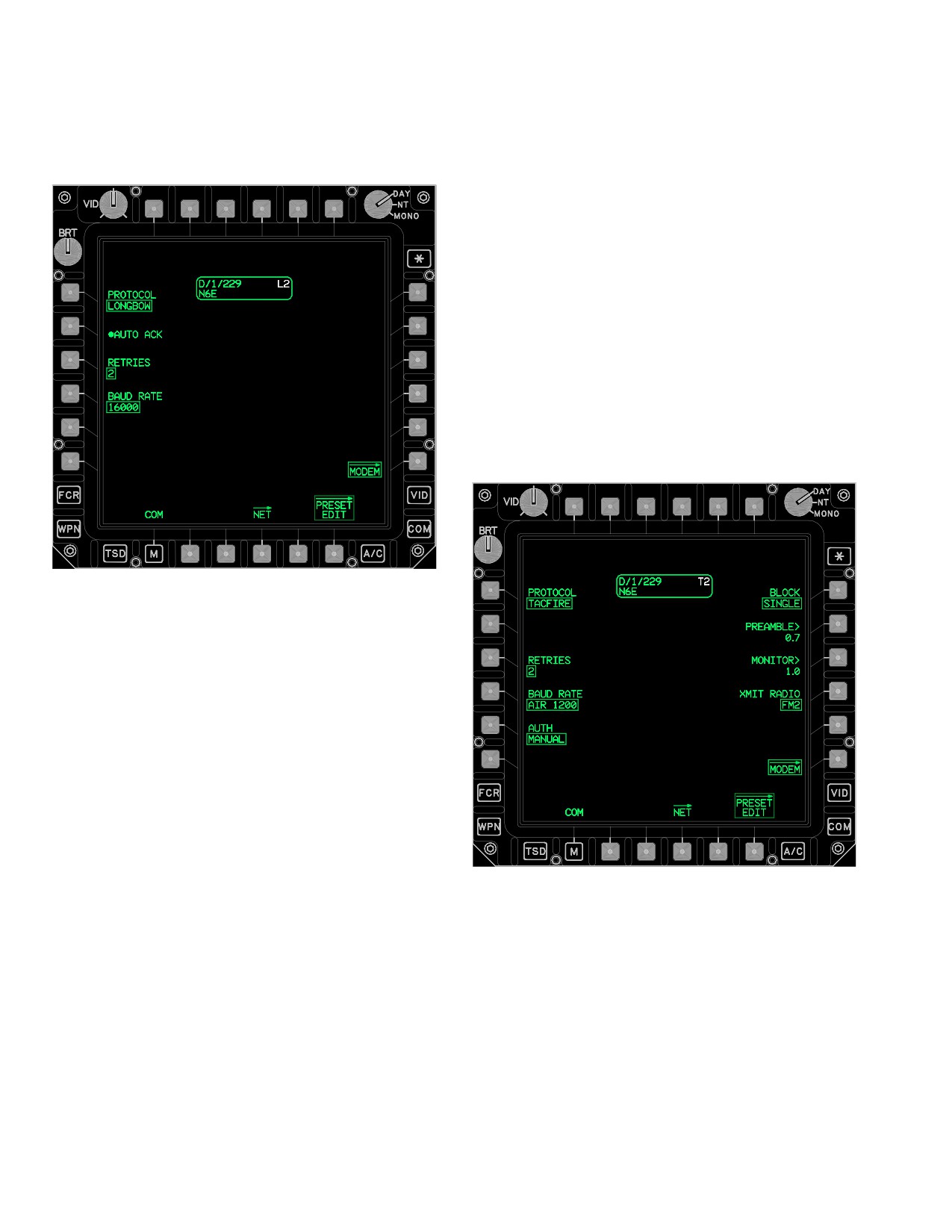
3.53AC.1 PROTOCOL Button. The PROTOCOL but-
b. RETRIES Button. The RETRIES button pro-
ton (fig 3-62Q) provides the capability to select LONG-
vides the capability to select the number of retransmis-
BOW, TACFIRE, or NONE.
sions the IDM performs (2, 1, or 0) with no acknowledge-
ment from a subscriber.
c. BAUD RATE Button. The BAUD RATE button
provides the following baud rate options:
• 16000
•
8000
• 2400
• 1200
•
600
• 300
•
150
• 75
3.53AC.3 TACFIRE PROTOCOL. When the multi-state
PROTOCOL button (fig 3-62R) is selected to TACFIRE, the
MODEM page displays the TACFIRE PROTOCOL buttons.
LBA5096
Figure 3-62Q. MODEM Page With LONGBOW
Selected
NOTE
The Longbow Protocol used in the IDM is
also known as the Air Force Applications
Program Development (AFAPD)
3.53AC.2 LONGBOW PROTOCOL. When the multi-
state PROTOCOL button is selected to LONGBOW, the
following unique buttons are displayed:
• AUTO ACK button
• RETRIES button
• BAUD RATE button
LBA - 5097
a. AUTO ACK Button. The AUTO ACK button pro-
vides the capability to enable or disable the auto acknowl-
Figure 3-62R. MODEM Page With TACFIRE
edge mode.
Selected
Use or disclosure of this information is subject to the restriction(s) on the title page of this document.
3-66.22
Change 3
TM 1-1520-251-10
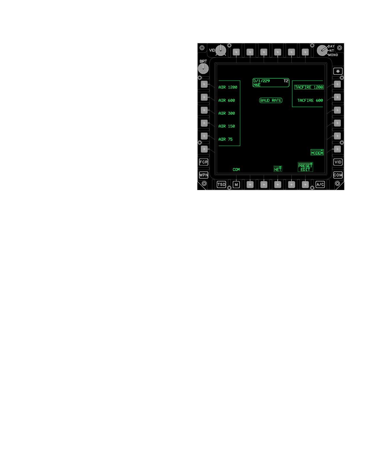
When the TACFIRE button is selected, the following
unique buttons are displayed:.
• RETRIES button
• BAUD RATE button
• AUTH button
• BLOCK button
• PREAMBLE button
• MONITOR button
• XMIT RADIO button
a. RETRIES Button. The RETRIES button pro-
vides the capability to select the number of retransmis-
sions the IDM performs (2, 1, or 0) with no acknowledge-
ment from a subscriber.
b. BAUD RATE Button. The BAUD RATE button
(fig 3-62S) provides baud rate options of:
• 1200
• 600
• 300
LBA - 5098
• 150
Figure 3-62S. MODEM Page With TACFIRE and
• 75
BAUD RATE Selected
TACFIRE 1200 and TACFIRE 600 are the only options
c. AUTH Button. The AUTH two - state button al-
available for TACFIRE messages sent to artillery. TAC-
lows the crew to toggle between NONE and MANUAL. If
FIRE 1200 is the default for the TACFIRE nets. The slow-
NONE is selected, no authentication is required. This
er rates for the AIR NETS are to be used only if reception
function automatically displays NONE due to use of auto-
is poor at high rates.
matic authentication. If MANUAL is selected, an operator
input of the transmission authenticator is required each
time transmission is attempted. MANUAL authentication
is normally only used in air - to - air or air - to - ground TAC-
FIRE. If MANUAL is selected, but no manual authentica-
tion is desired at the time of transmission, the message
will be sent on the second press of the SEND button.
d. BLOCK Button. The BLOCK two-state button al-
lows the crew to toggle between SINGLE and DOUBLE.
SINGLE BLOCK sends each segment of data once per
SEND. DOUBLE BLOCK sends each data segment twice
per SEND. DOUBLE should be used when atmospheric con-
ditions/reception are poor or when jamming is suspected.
NOTE
• A minimum preamble of 0.4 seconds is
required when transmitting through cryp-
to equipment. The longer the preamble,
the longer the air time.
• When establishing communications with
AFATDS, ensure that 2.3 seconds is used
by both the AH-64D and the artillery.
Use or disclosure of this information is subject to the restriction(s) on the title page of this document.
Change 3
3-66.23
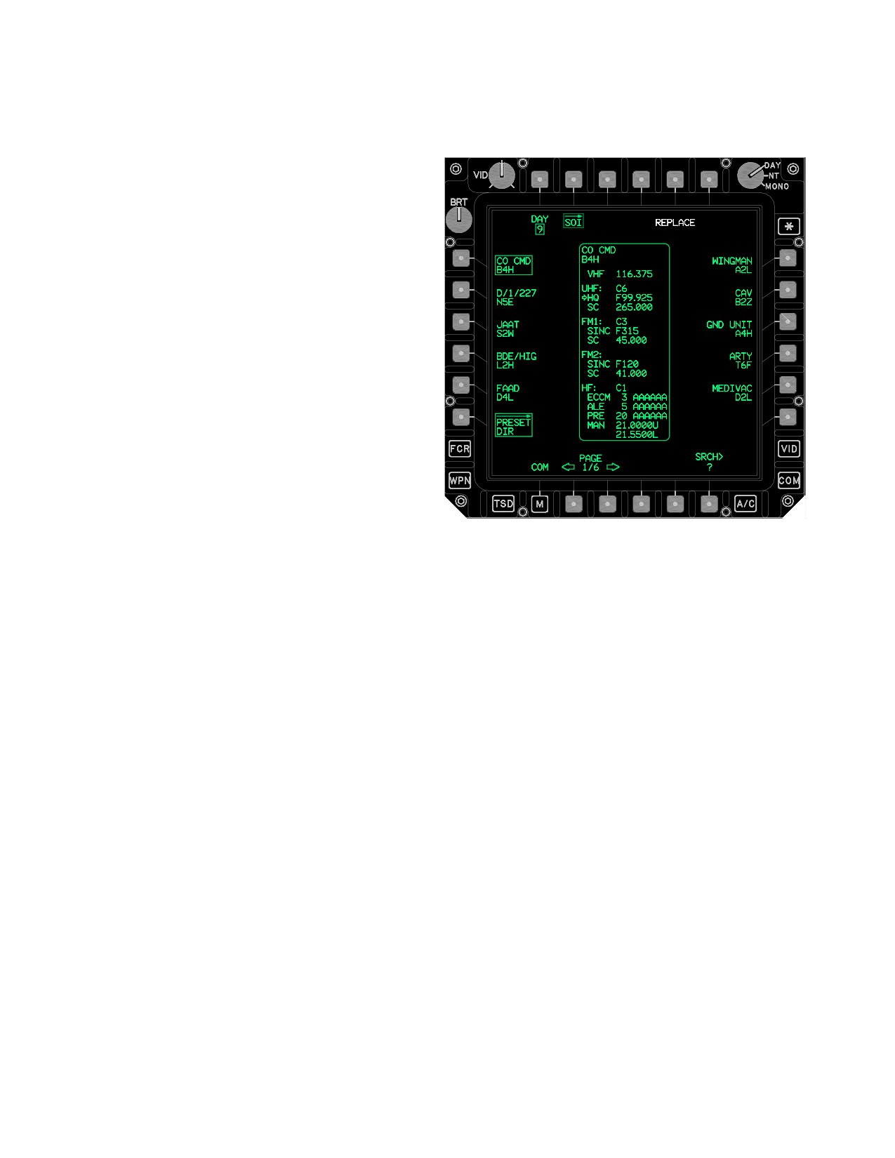
TM 1-1520-251-10
e. PREAMBLE Button. The PREAMBLE button is
the PRESET DIR button presented on either the COM
the ON AIR time that establishes a digital link between the
page or SOI page.
radios prior to the message being sent. Selecting the
PREAMBLE button provides the capability to modify this
ON AIR time. An interval between 0.1 and 9.9 seconds
may be entered.
f. MONITOR Button. Selection of the MONITOR
button allows the crew to modify the time that the IDM lis-
tens for interfering traffic prior to transmitting the mes-
sage. A time from 0.5 seconds to 9.9 seconds or OFF may
be entered. To turn this function off the crew must enter
zero, the word OFF is displayed on the ATHS page. If
more than 15 seconds have elapsed after the SEND but-
ton has been depressed, the IDM will reset automatically
and the SEND button must be pressed again. Voice trans-
mission has priority over digital transmission; therefore,
the IDM will wait until the airway is clear of voice traffic if a
monitor time has been selected.
g. XMIT RADIO Button. Selection of the multi -
state XMIT RADIO button allows the crew to select the ra-
dio that the IDM will use to transmit the TACFIRE digital
messages. Preset options of VHF, UHF, FM1, and FM2
are displayed upon selection of of the XMIT RADIO but-
LBA5180
ton. When the preset is selected and tuned to a radio, that
radio will be set at XMIT RADIO. After the preset has been
Figure 3-62T.
PRESET DIR Page
tuned to a radio, this button allows the operator to config-
ure it to a different radio. Artillery TACFIRE nets are nor-
The PRESET DIR page contains the following unique but-
mally set on FM1 or FM2.
tons:
3.53AD PRESET DIR PAGE
• T5
REPLACE button
• L1 - L5
PRESET buttons
The PRESET DIR page (fig 3-62T) accesses a pre - mis-
• R1 - R5
PRESET buttons
sion developed database of up to 60 digital/voice PRE-
SET items. The PRESET DIR page supports manual
• B2
PAGE BACK button
page searching, KU data searching, the selection of
• B3
PAGE FORWARD button
single PRESET items, and the replacement of COM page
• B5
ABORT button (conditional)
presets with PRESET items. The PRESET DIR page but-
ton is displayed following a DTU load and is accessed via
• B6
SRCH button
Use or disclosure of this information is subject to the restriction(s) on the title page of this document.
3-66.24
Change 2
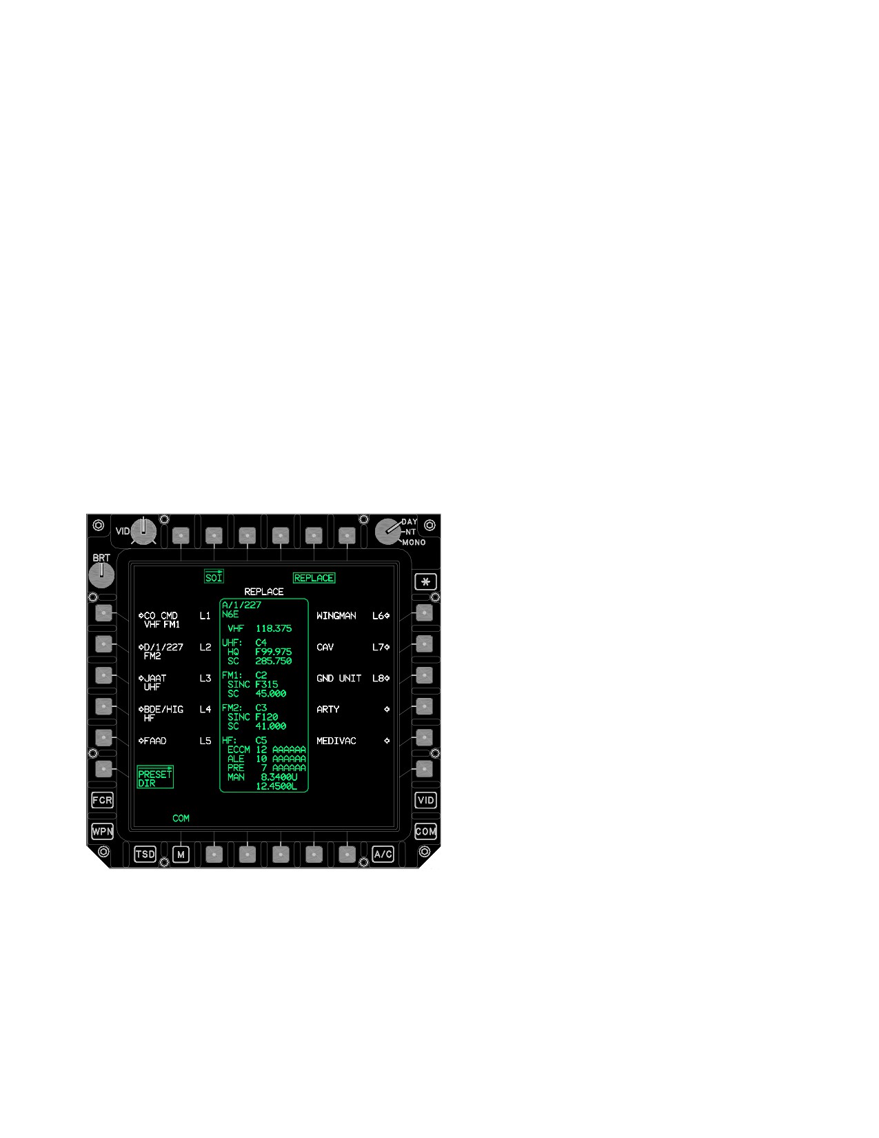
TM 1-1520-251-10
NOTE
3.53AD.2 PRESET Buttons. The PRESET DIR page
button provides access to a premission developed data-
Selecting the PRESET REPLACE location
base containing up to 60 PRESET items. Each of the
9 or 10 with a Longbow or Tacfire PRESET
PRESET items possess identical data type capabilities
item will store the COM and member data,
and capacities as does the COM page presets inclusive of
however, the net-type will be changed to
members. Upon the display of the page, the first valid
voice.
PRESET item will be selected and the corresponding
PRESET item status window (para 3A.32.33.53AD.3 and
3.53AD.1 REPLACE Button. The PRESET DIR
fig 3-62T) is displayed along with the PRESET item MEM-
LOCATION REPLACE format is displayed when the RE-
BER status window. Each PRESET item button contains
PLACE button (fig 3-62U) is selected. This display format
two lines of information, with the first line containing the
provides the means to replace any one of the ten COM
Unit ID field and the digital protocol fields. The second line
page presets with the selected PRESET item. When the
contains the Unit Call Sign field. The digital protocol as-
selected PRESET item is assigned with a Longbow or
signment is represented by the presence of either an L
Tacfire protocol, the REPLACE PRESET location display
(Longbow) or T (TACFIRE), which indicates the current
button locations 1 through 8 are white while presets 9
protocol of the selected PRESET Item.
through10 are green. The selection of any one of the
PRESET REPLACE location buttons commands the re-
3.53AD.3 PRESET ITEM Status Window. The PRE-
placement of that locations COM page preset with the se-
SET item status window (fig 3-62T) displays the field con-
lected PRESET items COM, IDM, and member data. Fol-
tents of the currently selected PRESET item. The primary
lowing the system’s successful processing of the
radio/mode and frequency/ECCM will be displayed in
replace - store operation, the COM page will display show-
white. Status window data fields includes:
ing that the replace was made.
•
Unit ID
• Call Sign
• IDM Type and IDM Preset - Net Number
• VHF Frequency
• UHF CNV status
• UHF HQ Net number
• UHF Single Channel Frequency
• FM1 CNV status
• FM1 SINC net number
• FM1 Single Channel Frequency
• FM2 CNV status
• FM2 SINC net number
• FM2 CNV status
• HF CNV status
• HF PRE
LBA5181
• HF ALE
• HF ECCM
Figure
3-62U.
PRESET DIR - REPLACE Button
Selected
• HF SC
Use or disclosure of this information is subject to the restriction(s) on the title page of this document.
Change 3
3-66.25
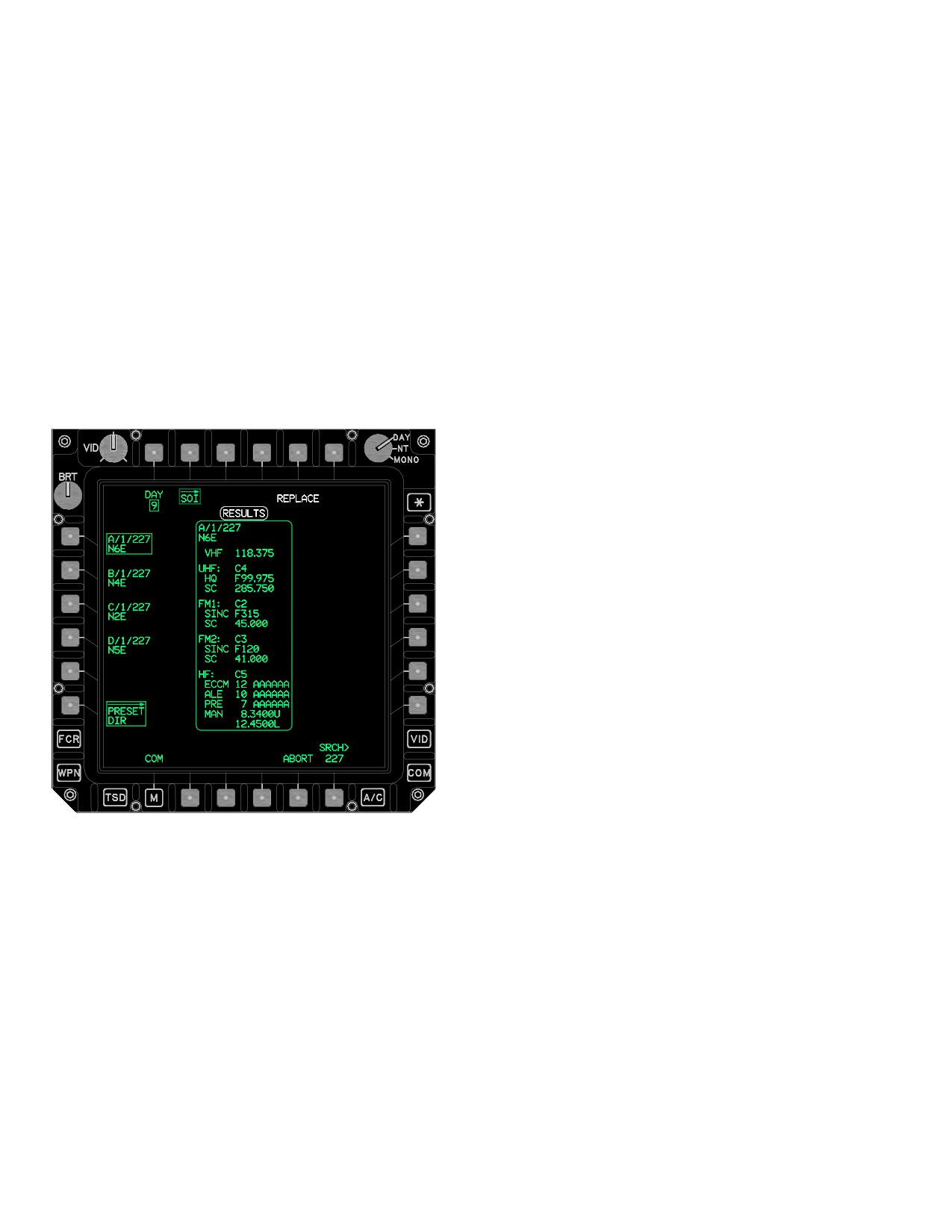
TM 1-1520-251-10
3.53AD.4 PRESET ITEM MEMBER Status Win-
The PRESET DIR page with search RESULTS posted
dow. The PRESET item MEMBER status window (fig
has the following unique button:
3-62T) displays the quantity of existing members for the
• B5
ABORT button
selected PRESET item. The status window displays the
PRESET item’s total member count field status as a num-
3.53AD.6 SRCH Button. The PRESET ITEM
ber of 0 through 15 followed by MEMBERS. PRESET item
SEARCH data entry button provides the means to search
members are not editable from the PRESET DIR page.
for a specific preset item in the preset directory’s data-
base. Searching and replacing functionality provides the
means to quickly replace Longbow, Tacfire, and Voice
3.53AD.5 ABORT Button. The ABORT button (fig
presets. The keyboard label reads PRESET SEARCH
3-62V) provides the means to abort a search during OIP
and the data entry may be all or a portion of either the Unit
or after search is complete. The ABORT button is dis-
ID or Call Sign of a preset. PRESET item search will begin
played when a search is initiated. Aborting a search re-
following the selection of KB ENTER key and an ABORT
stores the PRESET item page list and resets the page
button will display at this time.
number to one.
3.53AD.7 SRCH RESULTS Format. The PRESET DI-
RECTORY page posts and displays matched search re-
sults as they occur in a SEARCH RESULTS format. The
RESULTS status window (fig 3-62V) is displayed during a
search to reflect that the PRESET items being displayed
are matches to search data. Posted preset results may be
reviewed and stored while the search continues. The
PRESET list buttons control presentation of search result
pages. If there are 10 or less PRESET item matches
found in a search, then the page buttons will not be dis-
played.
3.53AD.8 NO MATCH Status Window. The NO
MATCH status window is displayed when there was no
match found during a preset PRESET DIR database item
search. When called, the NO MATCH status will be dis-
played in white in the location immediately above the
SRCH button.
3.53AE NET PAGE
The NET page displays the preset member data associat-
ed with the selected COM page preset - net, provides edit-
LBA5182
ing for 1-15 members for Longbow, Tacfire, and NONE
protocols. Additionally, it provides advisory status win-
dows for the selected net member’s Callsign/Suffix status
Figure
3-62V.
PRESET DIR Page - Database SRCH
and IDM digital ID settings and an abbreviated ownship
With RESULTS Posted
(para 3.53W.14) status window.
Use or disclosure of this information is subject to the restriction(s) on the title page of this document.
3-66.26
Change 3
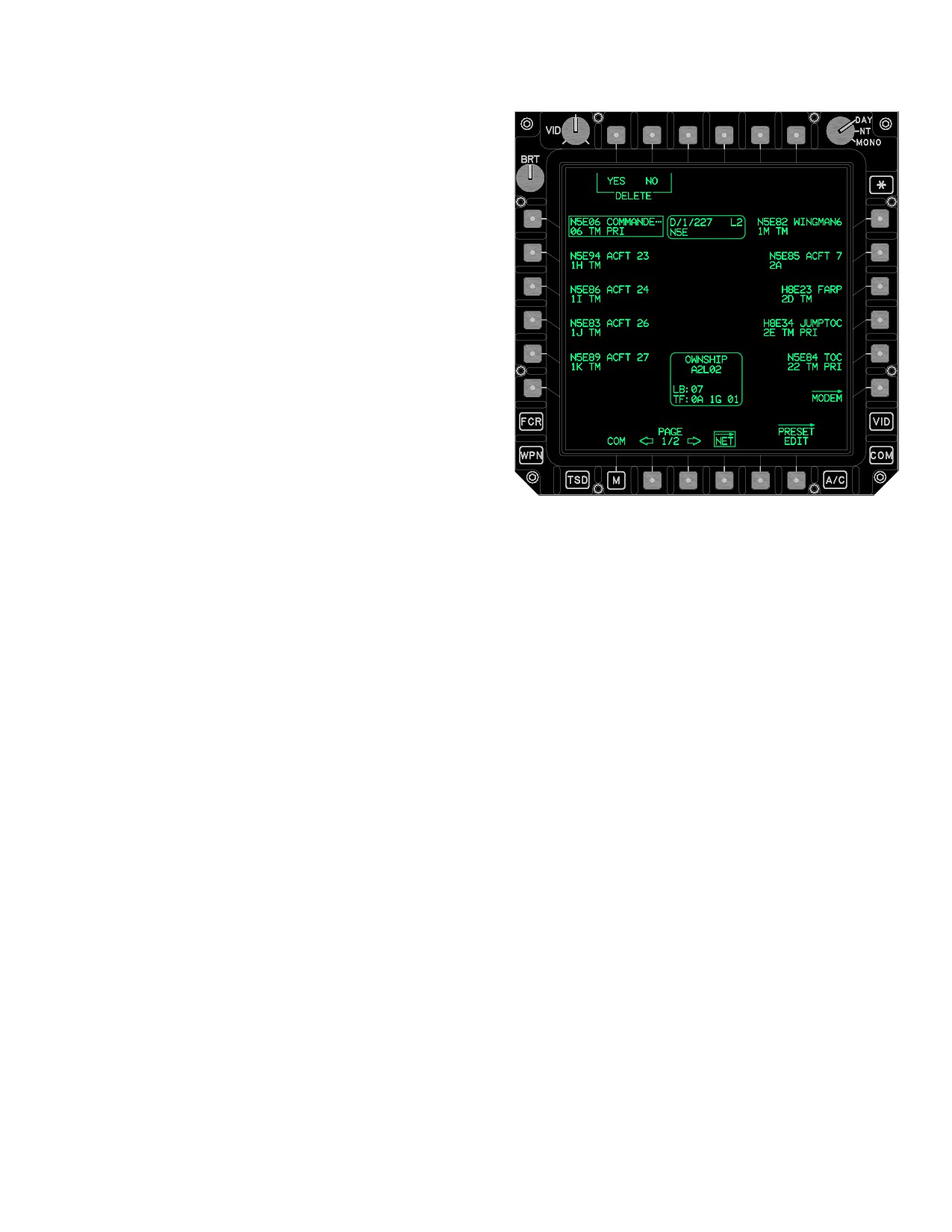
TM 1-1520-251-10
The NET (LONGBOW, TACFIRE, and NONE) page (fig
3-62W) has the following unique buttons:
• T1
SUFFX (Suffix) button
• T2
DEL (MEMBER) button
• T3
TEAM button
• T4
PRI button
• T5
C/S button
• T6
SUB button
• L1-L5
MEMBER buttons
• R1-R5
MEMBER buttons
• R6
MODEM button
LBA5183
• B2
PAGE Back button
Figure 3-62W. NET Page - (Longbow Team Member
• B3
PAGE Forward button
Selected)
3.53AE.1 SUFFX Button. The SUFFX button displays
• B5
CLEAR button
the SUFFX page (para 3.53AE.13).
3.53AE.2 MEMBER DEL Button. The MEMBER DEL
button provides the capability to delete the selected mem-
ber. This button is only displayed for a preset with an as-
signed IDM net and a valid call sign as displayed in the
MEMBER CALL SIGN button. Selection of the MEMBER
DEL button will prompt for a YES or NO confirmation to
initiate the deletion. Selecting the YES confirmed button
deletes the data associated with the selected MEMBER
button and returns the crewmember out of the member
delete confirmation mode. Selecting NO returns the crew-
member out of the member delete confirmation mode.
3.53AE.3 MEMBER TEAM Button. The TEAM button
provides the capability of toggling a net member’s team
designation on or off. Selecting the TEAM button assigns
and unassigns team member status independently of the
PRI (primary) status. Selecting the TEAM button will add
the selected member to the IDM net associated with the
currently displayed preset and display the TM status on
the second field of the selected MEMBERs button. This
button is only displayed if the net member currently se-
lected has a subscriber ID.
Use or disclosure of this information is subject to the restriction(s) on the title page of this document.
Change 3
3-66.27
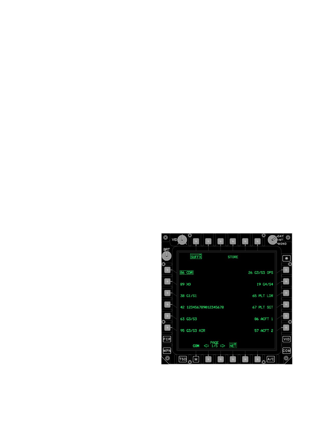
TM 1-1520-251-10
3.53AE.4 MEMBER PRI Button. The PRI (primary)
3.53AE.10 CLEAR Button. The CLEAR button, dis-
button provides the capability to toggle a net member’s
played in white, is only displayed if the IDM has detected
primary designation on or off. Selecting the PRI button as-
extraneous Longbow/Tacfire subscribers. This may occur
signs and unassigns primary member status indepen-
if the crew deletes subscribers from a Longbow/Tacfire
dently of the TEAM status. Selecting the PRI button will
net, but then performs an upload of the original Longbow/
add the selected member to the IDM net associated with
Tacfire member data from the DTC. Pressing the CLEAR
the currently displayed preset and display the PRI status
button will delete the extraneous Longbow/Tacfire sub-
on the second field of the selected MEMBER’s button.
scribers from the IDM.
This button is only displayed if the net member currently
selected has a subscriber ID and if there are not already
3.53AE.11 MEMBER Status Window. The net MEM-
seven members designated as primary members.
BER status (figs 3-62W and 3A-31) is displayed when a
net MEMBER is selected.
3.53AE.5 MEMBER C/S Button. The MEMBER C/S
The status window contains 3 fields:
data entry button provides the capability to edit or create
• Unit ID and Net Protocol
the selected members call sign. This button is only dis-
• Call Sign
played for a preset with an assigned IDM net. When se-
lected, the keyboard label will display CALL SIGN and will
• Suffix Descriptor
accept an entry of 3 to 5 characters.
3.53AE.12 MEMBER IDM Status Window. The net
MEMBER IDM status (fig 3-62W) window is displayed
3.53AE.6 MEMBER SUB ID Button. The preset net
when a net MEMBER is selected. The status window con-
MEMBER SUB ID data entry button provides the capabili-
tains five fields:
ty to edit, or create, the selected members Longbow or
Tacfire preset net subscriber ID. The preset net MEMBER
• LB (Longbow subscriber ID)
SUB ID button is displayed upon the selection of a MEM-
• TF (Tacfire subscriber ID)
BER button and Longbow or Tacfire is the selected proto-
col. The keyboard label displays SUBSCRIBER ID and
3.53AE.13 SUFFX Page Button. The SUFFX page (fig
accepts a one or two character input between 0 - 39, A - Z,
3-62X) displays the Suffix data that has been loaded from
1A - 1Z, 2A - 2Z, or 3A - 3I.
the DTC. The SUFFX page provides the capability to
modify members with a suffix.
3.53AE.7 MEMBER Buttons. The member buttons
provide the capability to create, edit, and assign/unassign
team and priority member status for up to 15 IDM preset
net members or create/edit up to 15 voice net members.
The preset net MEMBER buttons contain two fields of in-
formation. The first field contains the Call Sign ID and Suf-
fix Description. The second field contains the Digital ID,
Team Status, and Primary Status. The Call Sign ID is dis-
played with up to a five character free text descriptor. The
Suffix Description is displayed with up to the first eight
characters of the free text descriptor. When selected, a
preset net member status window (para 3A.33.15) and
net member IDM status window (para 3A.33.16) will be
displayed providing a display of the selected member’s
COM and digital data.
3.53AE.8 MODEM Page Button. The MODEM button
displays the MODEM page (para 3.53AC).
3.53AE.9 PAGE Back and PAGE Forward But-
LBA5108
tons. Allows selection between two pages of preset
members.
Figure 3-62X. SUFFX Page - (Net Member Selected)
Use or disclosure of this information is subject to the restriction(s) on the title page of this document.
3-66.28
Change 3
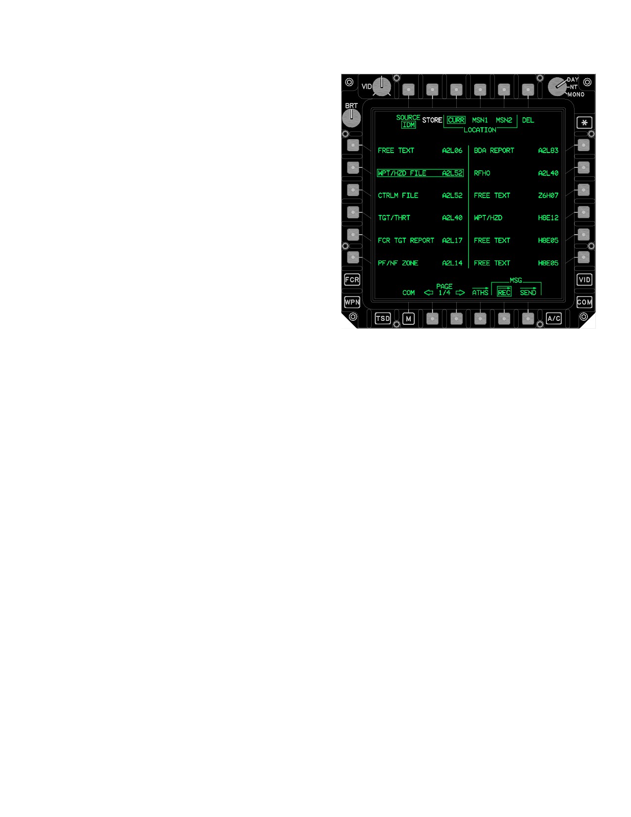
TM 1-1520-251-10
The SUFFX page contains the following unique buttons:
• T4
STORE button
• L1-L6
Suffix buttons
• R1-R6
Suffix buttons
• B2
PAGE Back button
• B3
PAGE Forward button
3.53AE.14 STORE Button. Selecting the STORE but-
ton provides the capability to store the selected Suffix into
a selected preset net member button location on the NET
page. Also as part of this selection, a new subscriber call
sign for the NET MEMBER selected is created using the
selected Preset’s call sign and the selected Suffix ID. This
button is displayed in white.
LBA - 5073A
3.53AE.15 Suffix Buttons. The Suffix buttons are dis-
played on the left and right sides of the SUFFX page.
Figure 3-62Y. MSG REC Page (Source IDM)
3.53AE.16 PAGE Back and PAGE Forward But-
The MSG REC page contains the following unique but-
tons. Allows selection of multiple pages of suffixes.
tons:
• T2
SOURCE button
• T2
STORE/RVW button
3.53AF MSG REC PAGE
• T3
LOCATION CURR button (Longbow)
• T4
LOCATION MSN1 button (Longbow)
The MSG REC page (fig 3-62Y) provides the operator the
capability to manage IDM messages that are received
• T5
LOCATION MSN2 button (Longbow)
within the IDM’s message receive buffer or to manage HF
• T6
DEL button
messages that are received within the HF radio’s receive
• L1-L6
Message Receive buttons
buffer. The crew is cued when a message is received by a
EUFD advisory, message receive tone (para 2.139, table
• R1-R6
Message Receive buttons
2-15) and the message appearing on the MSG REC page.
• B2
PAGE Back button
Additionally, Longbow messages received containing
• B3
PAGE Forward button
TSD data messages will cue the crew by displaying a
REC button on the TSD page.
• B4
ATHS Page button
Use or disclosure of this information is subject to the restriction(s) on the title page of this document.
Change 3
3-66.29
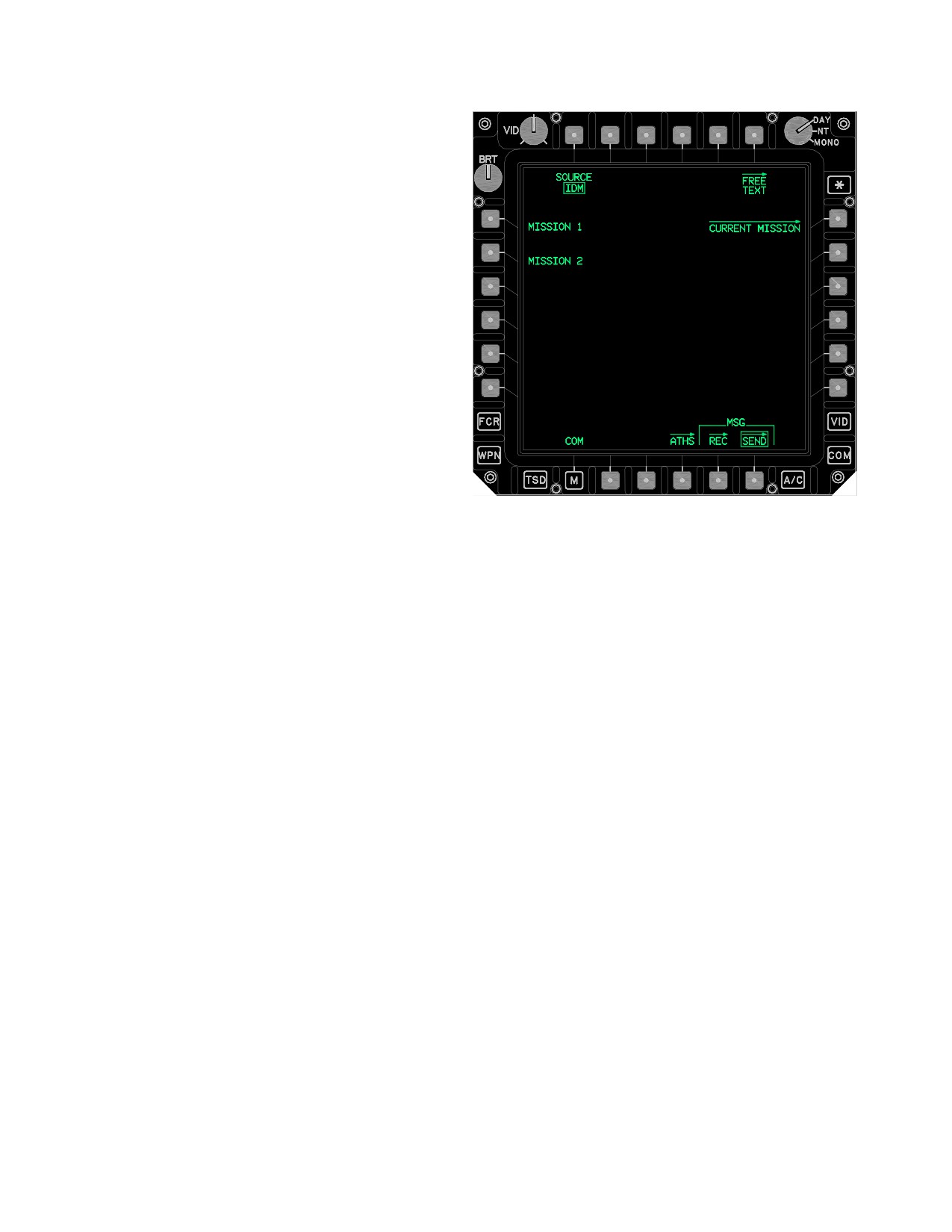
TM 1-1520-251-10
NOTE
Storage of an IDM message will overwrite
the selected mission data.
3.53AF.1 SOURCE Button. The SOURCE button
toggles between IDM or HF message receive controls and
messages.
3.53AF.2 STORE/RVW Button. The STORE/RVW button
provides the capability to store a data message or review
(para 3A.35.9) a FREE TEXT (Longbow) message, or any
ATHS message received via the IDM. The STORE and RVW
buttons will display after an applicable message has been se-
lected. The STORE button stores the data associated with
the selected Message button and then deletes the message
LBA5184
from the IDM buffer. If a TACFIRE message is selected for
Figure 3-62Z. MSG SEND Page
review, then upon activation of the RVW button the page will
automatically switch to the page MSG REC page of the
3.53AF.4 DEL Button. Selecting the DEL button de-
letes the IDM message associated with the selected mes-
ATHS TACFIRE. Refer to the ATHS section for more infor-
sage button.
mation.
3.53AF.5 Message Buttons. There can be up to 12 mes-
sage buttons per page (fig 3A-37) and up to 13 pages. On
the top line, the type of message will be displayed, along with
the protocol the message was received on. If the message is
NOTE
not valid per the indicated type a “?” will be displayed at the
beginning of the second line. The call sign of the sender is
The LOCATION MSN1 or MSN2 buttons are
displayed at the end of the second line. If the sender is a
barriered anytime that a Longbow data mes-
subscriber to one of the presets, the call sign will be
sage is selected and the mission card is not
displayed, otherwise a “?” will be displayed. New incoming
messages are displayed at the end of the buffer.
available, corrupt, or busy with a different task.
3.53AF.6 PAGE Back and PAGE Forward Buttons. Al-
lows selection of multiple pages of received IDM messages.
3.53AF.7 ATHS Page Button. The ATHS button (fig
3.53AF.3 LOCATION CURR / MSN1 / MSN2 But-
3A-39) displays the ATHS page.
tons. The MSG REC page CURR, MSN1, and MSN2 but-
3.53AF.8 RVW Message Window. The RVW message
tons (fig 3-62Z) provide the capability to specify where a
window (fig 3A-39) allows the crewmembers to review text
Longbow message file, or files, will be stored. Selecting the
based messages (Free Text) received over the IDM. The
CURR button will store the selected Longbow message or
status window can display up to 19 lines of 44 characters.
messages to the current (active) locations and displays. Se-
When used with the PAGE Back and PAGE Forward
buttons, up to six pages of a message can be viewed. The
lecting the MSN1 or MSN2 buttons will store the message, or
MSG REC page contains the following unique buttons
messages, to either MISSION1 or MISSION2 on the DTC.
when SOURCE is HF:
Use or disclosure of this information is subject to the restriction(s) on the title page of this document.
3-66.30
Change 3
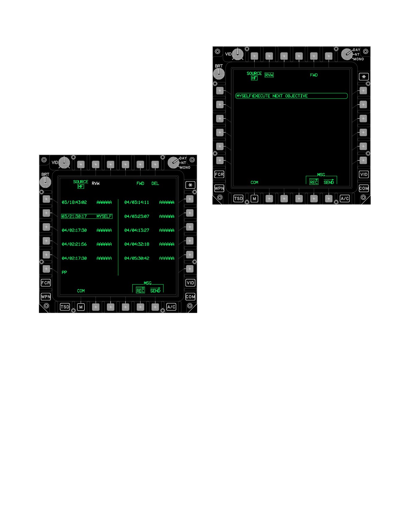
TM 1-1520-251-10
• T2
RVW button
• T5
FWD button
• T6
DEL button
• L1-L5
Message Receive buttons
• L6
PP Receive button
• R1-R5
Message Receive buttons
3.53AF.9 FWD Button. The FWD button (figs 3-62AA
and 3-62AB) transmits the HF message associated with
the selected MSG REC HF MSGS button on the current
frequency or mode.
LBA - 5077
Figure 3-62AB. MSG REC Page (HF RVW Selected)
3.53AF.10 DEL Button. Selecting this button deletes
the HF message associated with the selected Message
Receive button. Selection of the DEL button will prompt
for a YES or NO confirmation to initiate the deletion.
3.53AF.11 Message Receive Buttons. There can be
up to 10 messages buttons (fig 3-62AA). The message
will be displayed with the day and time it was received and
the first six characters from the sender’s call address.
3.53AF.12 PP Receive Button. The PP button (fig
LBA5076
3-62AC) provides controls to store or delete a present
position report. The PP button is displayed when a pres-
Figure 3-62AA. MSG REC Page (Source HF)
ent position report is received over the HF radio.
Use or disclosure of this information is subject to the restriction(s) on the title page of this document.
Change 3
3-66.31
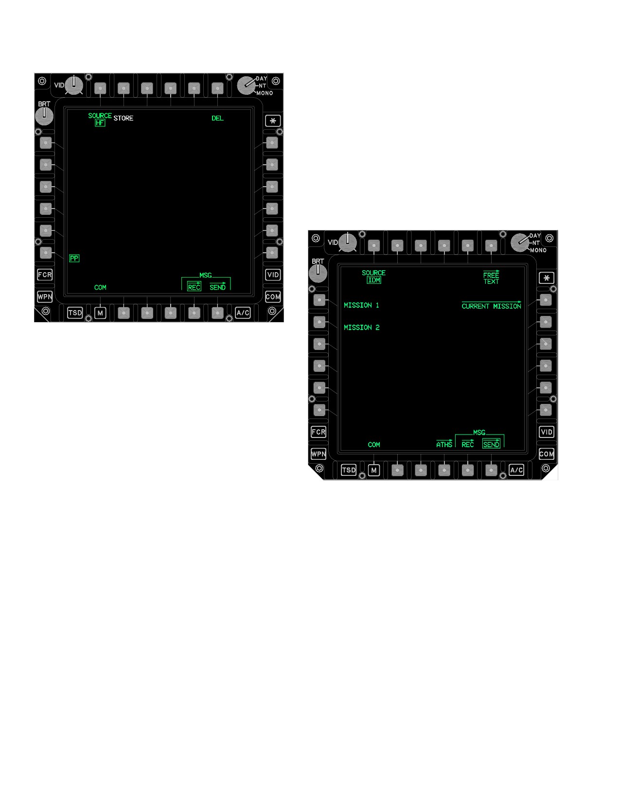
TM 1-1520-251-10
3.53AG MSG SEND PAGE
The MSG SEND page (fig 3-62AD) provides controls to
send MISSION 1 or MISSION 2 data files via the IDM to
Longbow protocol team members. It also provides
access to the SET page which is used to configure the
IDM and message parameter defaults. It also provides
access to the CURRENT MISSION page which is used for
sending selected components of the current mission to
team members. Additionally, HF preprogrammed and
present position reports can be sent from the MSG SEND
page (fig 3-62AE).
LBA - 5078
Figure 3-62AC. MSG REC Page (HF PP Selected)
3.53AF.13 Free Text Message Window. The Free Text
Message Window (fig 3-62AB) allows the crewmembers
to review Free Text messages received over the HF radio.
The MSG REC page contains the following unique but-
LBA5185
tons when SOURCE is HF and PP is selected:
Figure 3-62AD. MSG SEND Page
• T2
STORE button
• T6
DEL button
The MSG SEND page contains the following unique but-
tons:
3.53AG.14 STORE Button. The HF PP STORE button
• T1
SOURCE button
(fig 3-62AC) provides the capability to store a present
• L1
MISSION 1 button
position report received over the HF radio into the control
measures file, location 92.
• L2
MISSION 2 button
• R1
CURRENT MISSION button
• R6
SEND button
3.53AF.15 DEL Button. Selecting this button deletes
the HF present position report. Selection of the HF PP
3.53AG.1 SOURCE Button. The SOURCE button
DEL button will prompt for a YES or NO confirmation to
toggles between IDM or HF message sending controls
initiate the deletion.
and messages.
Use or disclosure of this information is subject to the restriction(s) on the title page of this document.
3-66.32
Change 3
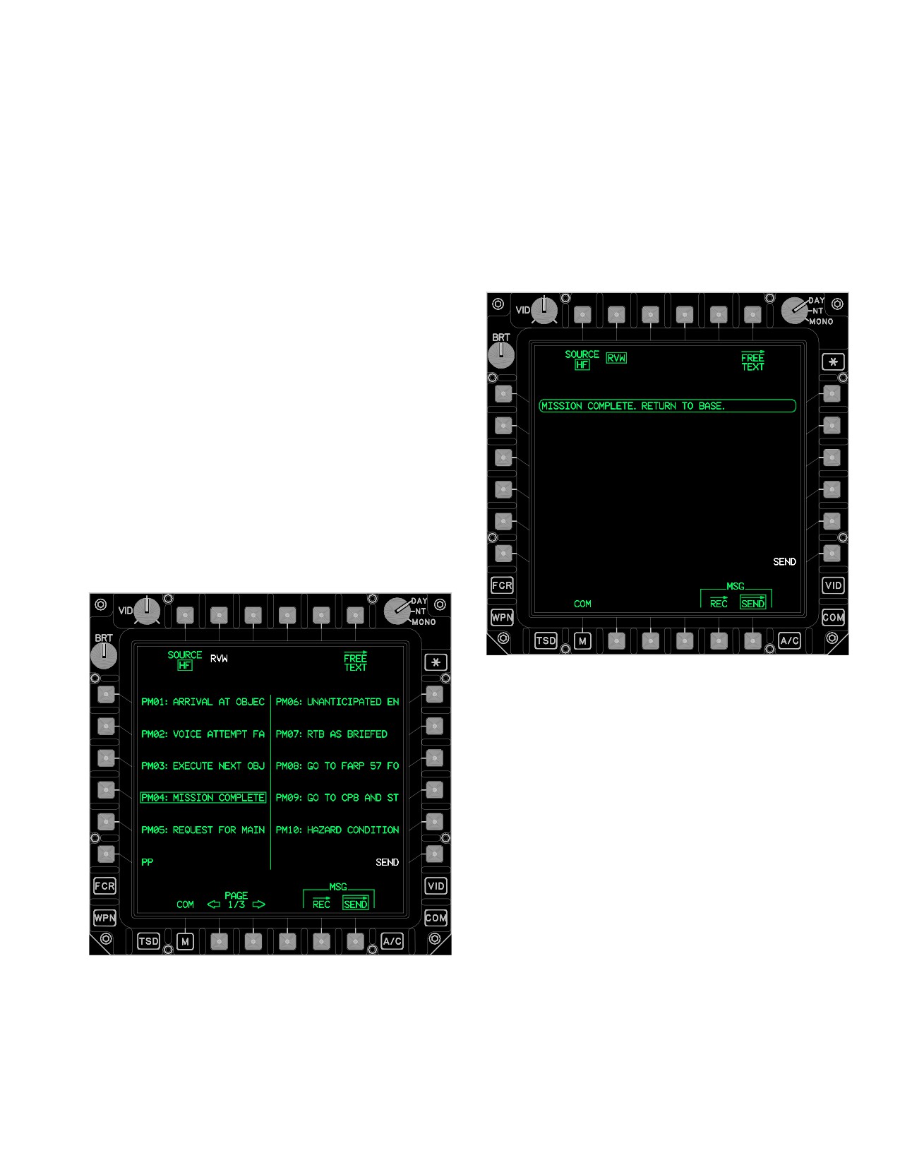
TM 1-1520-251-10
3.53AG.2 MISSION 1 (or 2) Buttons. The MISSION
3.53AG.5 RVW Button. The RVW button (fig 3-62AF)
buttons provide the capability to transmit the MISSION 1
allows the crewmembers to review the selected prepro-
(or 2) files to selected Longbow protocol team members
grammed Free Text message before sending it over the
upon the selection of the IDM SEND button.
HF radio.
3.53AG.3 CURRENT MISSION Button. The CUR-
RENT MISSION button displays the LONGBOW protocol
CURRENT MISSION page.
3.53AG.4 SEND Button. The selection of the SEND
button will command the system to transmit the selected
files through the selected IDM channel. The data is only
sent to team members.
The MSG SEND page contains the following unique but-
tons when SOURCE is HF (fig 3-62AE):
• T2
RVW button
• L1 - L5
Message Send buttons
• L6
PP Send button
• R1 - R5
Message Send buttons
• R6
SEND button
• B2
PAGE Back button
• B3
PAGE Forward button
• B4
ABORT button
LBA5113
Figure 3-62AF. MSG SEND Page (HF RVW
Selected)
3.53AG.6 Message Send Buttons. There can be up to
10 preprogrammed text message buttons per page, up to
3 pages. The preprogrammed text messages are num-
LBA5112
bered PM01 to PM25 with the first 16 characters of each
Figure 3-62AE. MSG SEND Page (Source HF)
message displayed.
Use or disclosure of this information is subject to the restriction(s) on the title page of this document.
Change 3
3-66.33
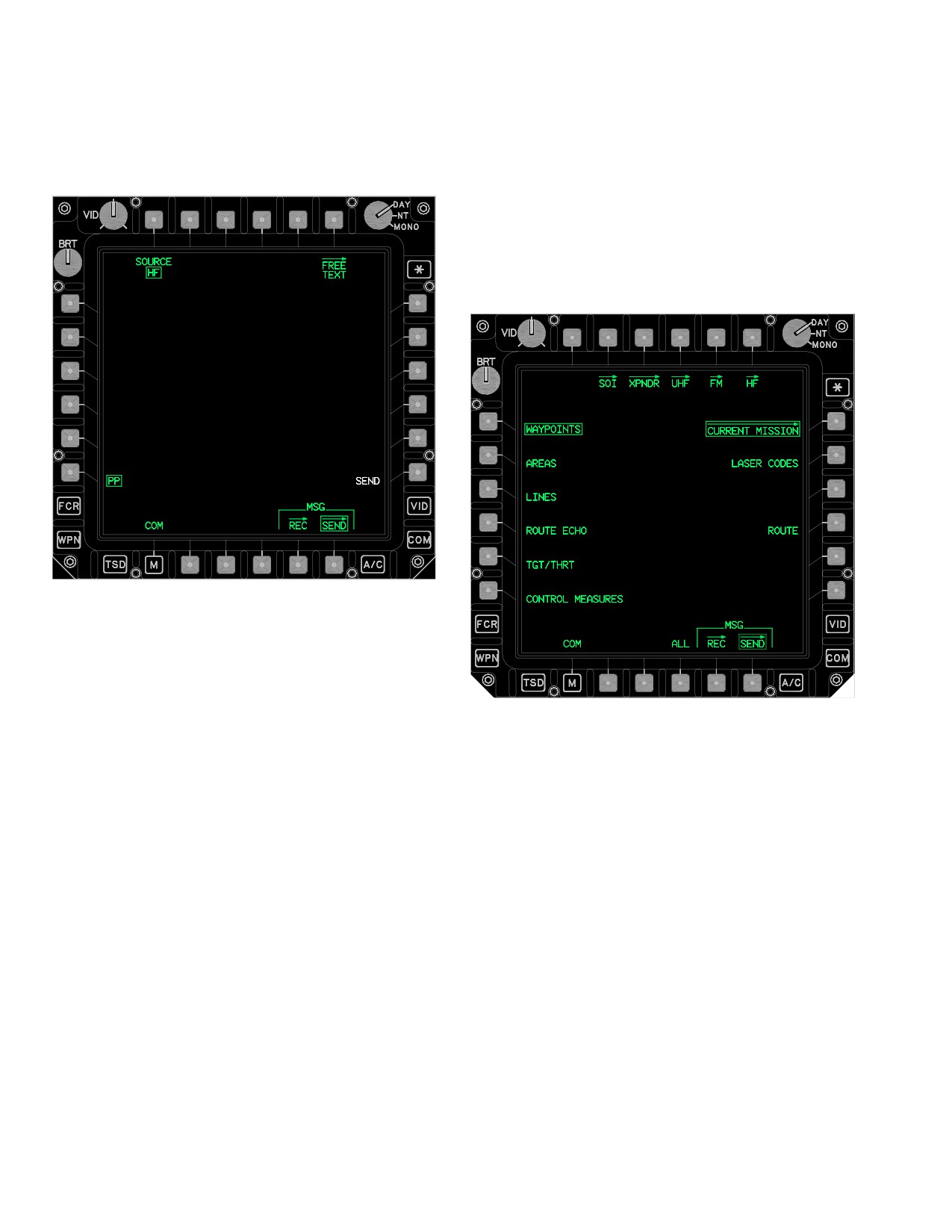
TM 1-1520-251-10
3.53AG.7 PP Send Button. The PP send button (fig
3.53AH CURRENT MISSION PAGE
3-62AG) provides the capability to send the ownship pres-
ent position over the HF radio’s modem.
The CURRENT MISSION button displays the CURRENT
MISSION page (fig 3-62AH). The CURRENT MISSION
page provides the capability to individually select the type
of information to be sent over the IDM using Longbow
(AFAPD) protocol. Selection of the ALL button allows
transmission of all current files. Once an item is selected,
selecting the SEND button will initiate transmission over
the IDM.
LBA5114
Figure 3-62AG. MSG SEND Page (HF PP Selected)
3.53AG.8 SEND Button. The SEND button transmits
LBA - 5115B
the HF message through the radio’s modem.
Figure 3-62AH. CURRENT MISSION Page
3.53AG.9 PAGE Back and PAGE Forward But-
tons. Allows selection of multiple pages of prepro-
grammed HF text messages.
The CURRENT MISSION page contains the following
unique buttons:
3.53AG.10 ABORT Button. The ABORT button is dis-
• L1
WAYPOINTS button
played while the HF message is being sent, in order to al-
• L2
AREAS button
low the crew to abort the transmission.
•
L3
LINES button
The MSG SEND page contains the following unique but-
• L4
ROUTE (CURRENT) button
tons when SOURCE is HF and PP is selected:
• L5
TGT/THRT button
• L6
CONTROL MEASURES button
• R6
SEND button
•
R2
LASER CODES button
3.53AG.12 SEND Button. The SEND button transmits
• R6
SEND button
the ownship present position through the HF radio’s mo-
• B3
ROUTE button
dem.
• B4
ALL button
3.53AG.13 ABORT Button. The ABORT button is dis-
3.53AH.1 WAYPOINTS Button. The WAYPOINTS but-
played while the present position report is being sent, in
ton allows sending of the current waypoints file over the
order to allow the crew to abort the transmission.
IDM.
Use or disclosure of this information is subject to the restriction(s) on the title page of this document.
3-66.34
Change 3
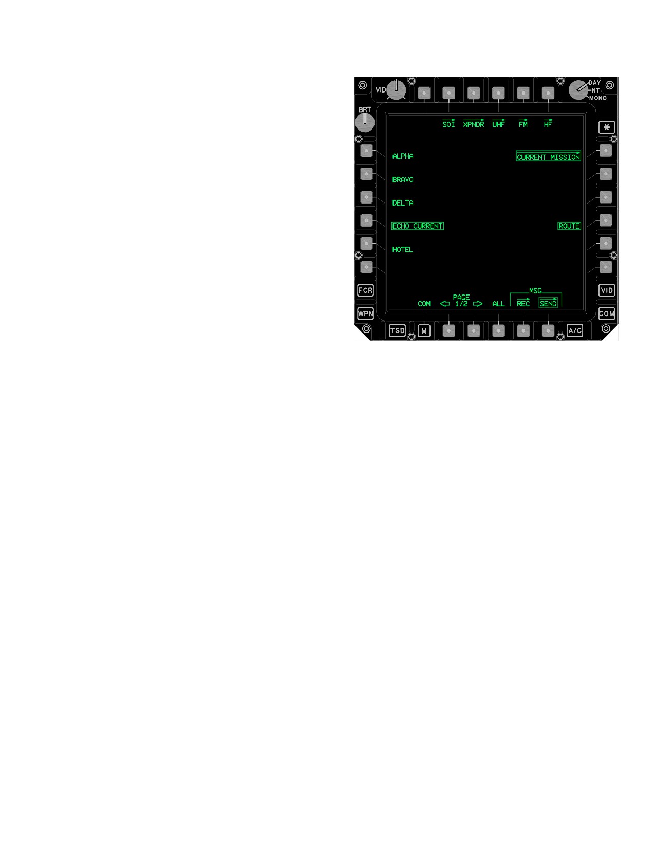
TM 1-1520-251-10
3.53AH.2 AREAS Button. The AREAS button allows
sending of the current engagement areas file over the
IDM.
3.53AH.3 LINES Button. The LINES button allows
sending of the current phase lines file over the IDM.
3.53AH.4 TGT/THRT Button. The TGT/THRT button
allows sending of the current target and threats file over
the IDM.
3.53AH.5 CONTROL MEASURES Button. The CON-
TROL MEASURES button allows sending of the current
control measures file over the IDM.
3.53AH.6 LASER CODES Button. The LASER
CODES button allows sending the current laser codes file
over the IDM.
3.53AH.7 SEND Button. The SEND button is only dis-
played if a valid CURRENT MISSION file is selected to be
sent. The selection of the SEND button will command the
LBA - 5116B
system to transmit the selected files through the selected
channel of the IDM. The selection of the SEND button will
command the system to transmit the selected files
Figure
3-62AI.
CURRENT MISSION Page (ROUTE
through the selected LONGBOW protocol channel of the
Button Selected)
IDM. The data is only sent to LONGBOW team members.
3.53AH.8 ROUTE Button. The ROUTE button allows
The ROUTE button provides the following unique buttons:
sending of the current route file over the IDM. The ROUTE
button presents all of the current routes files available for
• L1-L6
ROUTE buttons
sending over the IDM (fig 3-62AI).
• R2 - R5
ROUTE buttons
3.53AH.9 ALL Button. The ALL button allows sending
• B4
ALL button
of all current mission files over the IDM.
3.53AI.1 ROUTE Buttons. The ROUTE buttons allow
3.53AI CURRENT MISSION - ROUTE SELECTIONS
selection of a single route file to send over the IDM.
The ROUTE button (fig 3-62AI) provides the capability to
select various routes for sending over the Longbow IDM
3.53AI.2 ALL Button. The ALL button allows sending
protocol.
of all route files over the IDM.
Use or disclosure of this information is subject to the restriction(s) on the title page of this document.
Change 3
3-66.35
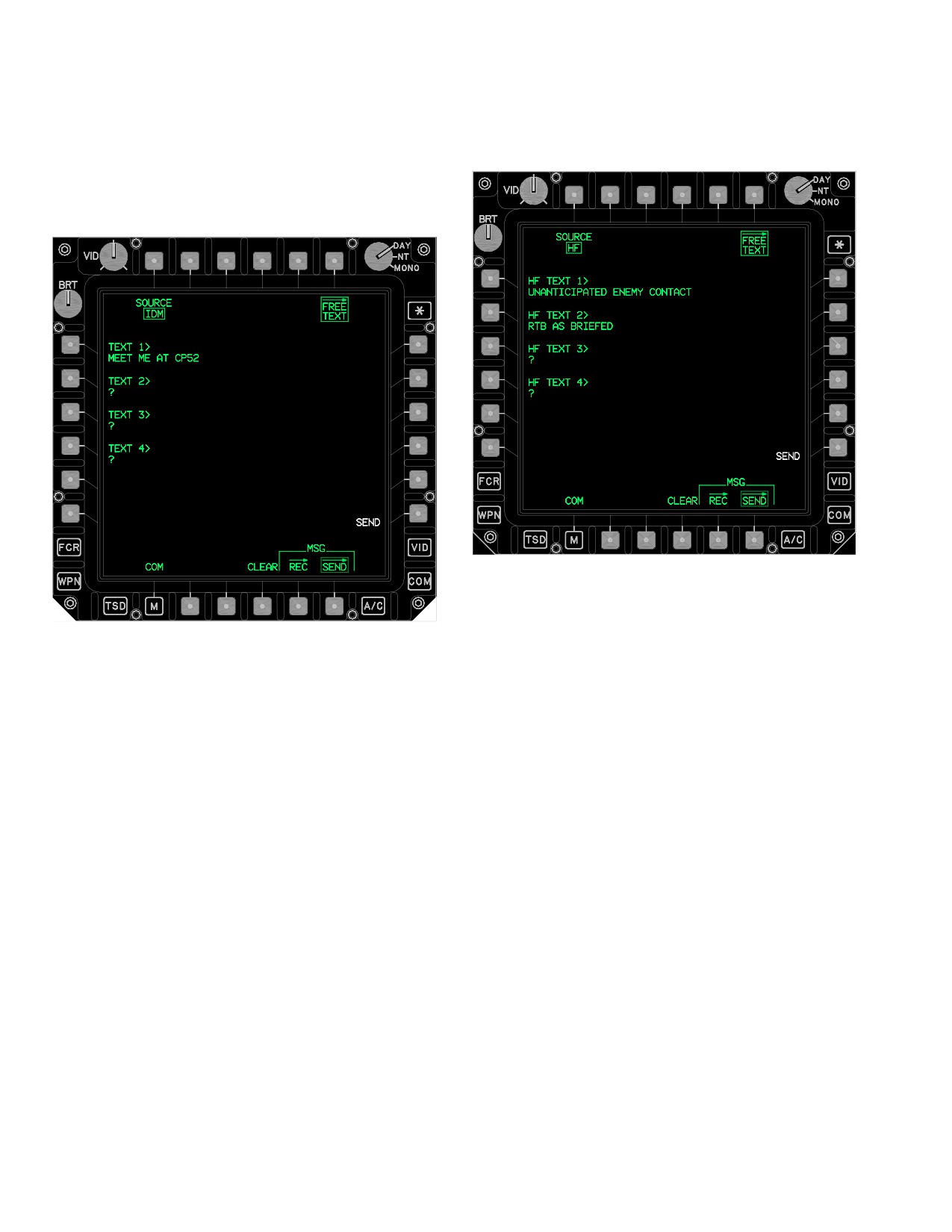
TM 1-1520-251-10
3.53AJ FREE TEXT PAGE
3.53AJ.4 CLEAR Button. The CLEAR button clears
the data contained in the IDM TEXT buttons.
The FREE TEXT page (fig 3-62AJ and 3-62AK) provides
the capability to create a free text message for transmis-
sion through the IDM using Longbow, protocols.
LBA5118
Figure 3-62AK. FREE TEXT Page (Source HF)
LBA - 5117A
The FREE TEXT page contains the following unique but-
tons when SOURCE is HF:
Figure 3-62AJ. FREE TEXT Page (Source IDM)
• L1-L4
HF TEXT (1-4) buttons
The FREE TEXT page contains the following unique but-
• R6
SEND button
tons when SOURCE is IDM:
• B4
CLEAR or ABORT button
• T1
SOURCE button
3.53AJ.5 HF TEXT Buttons. Each HF TEXT (1-4) but-
• L1-L4
IDM TEXT (1-4) buttons
ton provides the capability to load four 44-character mes-
sages into the system for transmission by the HF radio.
• R6
SEND button
• B4
CLEAR button
3.53AJ.6 SEND Button. The SEND button transmits
the HF TEXT message through the HF radio’s modem.
3.53AJ.1 SOURCE Button. The SOURCE button
toggles between IDM or HF free text message controls.
3.53AJ.7 CLEAR/ABORT Buttons. The CLEAR but-
ton clears the data contained in the HF TEXT buttons. The
3.53AJ.2 IDM TEXT Buttons. Each IDM TEXT (1-4)
ABORT button is displayed while the HF TEXT is being
button provides the capability to load four 44-character
sent, in order to allow the crew to abort the transmission.
messages into the system for transmission by the IDM or
HF radio.
3.53AK SIGNAL OPERATING INSTRUCTIONS (SOI)
Page
3.53AJ.3 SEND Button. The SEND button transmits
the IDM TEXT message through the selected channel of
The SOI page (fig 3-62AL) provides the capability to au-
the IDM or through the HF’s modem. With SOURCE to
thenticate communication transmissions and access ex-
IDM, the data is only sent to team members.
panders.
Use or disclosure of this information is subject to the restriction(s) on the title page of this document.
3-66.36
Change 3
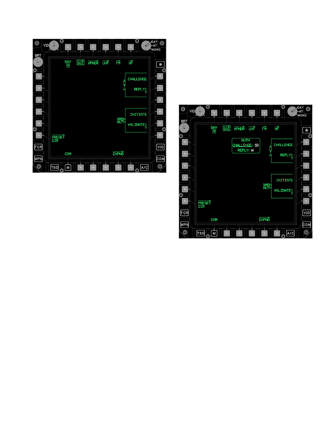
TM 1-1520-251-10
3.53AK.2 PRESET DIR Page Button. The PRESET
DIR button displays the preset data base for selection and
storage to one of the ten locations on the COM page (para
3A.32 and fig 3A-27).
3.53AK.3 AUTH CHALLENGE Button. The AUTH
CHALLENGE button provides the capability to extract the
challenge/reply table and display the codes within the
AUTH CHALLENGE REPLY window (fig 3-62AM ).
LBA5119
Figure 3-62AL. SOI Page
The SOI page contains the following unique buttons:
• T1
DAY button
• L6
PRESET DIR page button
• R1
AUTH CHALLENGE button
• R2
AUTH REPLY button
LBA5120
• R4
XMSN AUTH INITIATE button
Figure 3-62AM. SOI Page - AUTH CHALLENGE
• R5
XMSN AUTH VALIDATE button
• B5
EXPND (Expander) page button
3.53AK.4 AUTH REPLY Button. The AUTH REPLY
3.53AK.1 DAY Button. The DAY button provides the
button provides the capability to enter a challenge code
capability to toggle between the two different days of SOI
and extract the reply code from the challenge/reply table
data that are displayed within the communications sub-
and display the code within the AUTH CHALLENGE RE-
system.
PLY window (fig 3-62AN).
Use or disclosure of this information is subject to the restriction(s) on the title page of this document.
Change 3
3-66.37
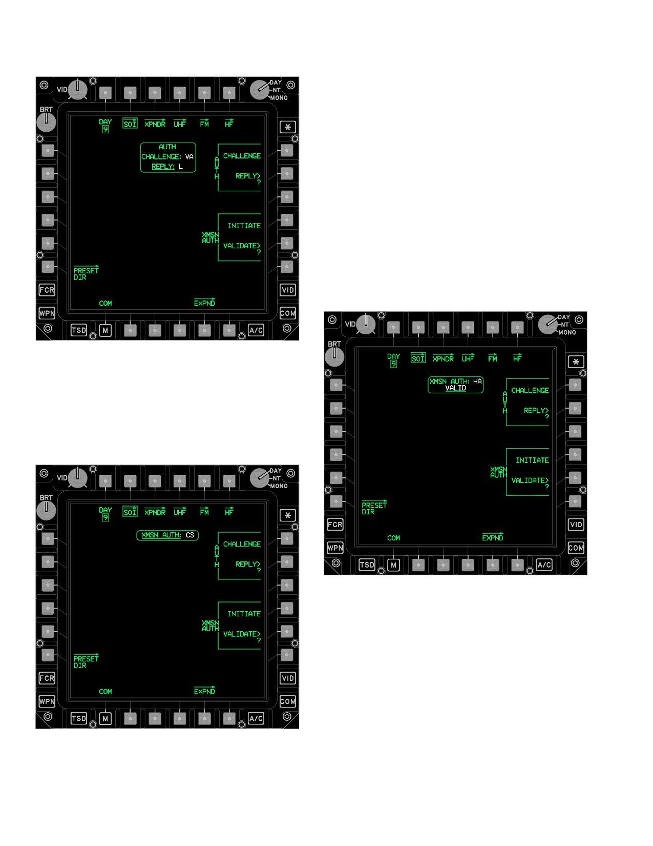
TM 1-1520-251-10
NOTE
An ALL CODES USED message will be dis-
played in white when all the codes have
been used.
3.53AK.6 XMSN AUTH VALIDATE Button. The
XMSN AUTH VALIDATE button (fig 3-62AP) provides the
capability to verify a transmit authentication code from the
transmit authentication table. The VALID label is dis-
played when the transmit authentication matches the
transmit authentication code entered through the KU. The
INVALID label is displayed when the transmit authentica-
tion table does not match the transmit authentication code
entered through the KU.
LBA5121
Figure 3-62AN. SOI Page - AUTH REPLY
3.53AK.5 XMSN AUTH INITIATE Button. The XMSN
AUTH INITIATE button extracts the transmit authentica-
tion codes and displays them in the XMSN AUTH window
(fig 3-68AO).
LBA5123
Figure 3-62AP. SOI Page - XMSN AUTH VALIDATE
3.53AL EXPANDER (EXPND) PAGE
The EXPND page (fig 3-62AQ), a view - only page, pro-
vides the capability to view the expander lookup table.
LBA5122
The expander lookup table displays the one character ex-
pander and descriptor field. Up to 26 expanders may be
Figure 3-68AO. SOI Page - XMSN AUTH INITIATE
displayed from the lookup table.
Use or disclosure of this information is subject to the restriction(s) on the title page of this document.
3-66.38
Change 3
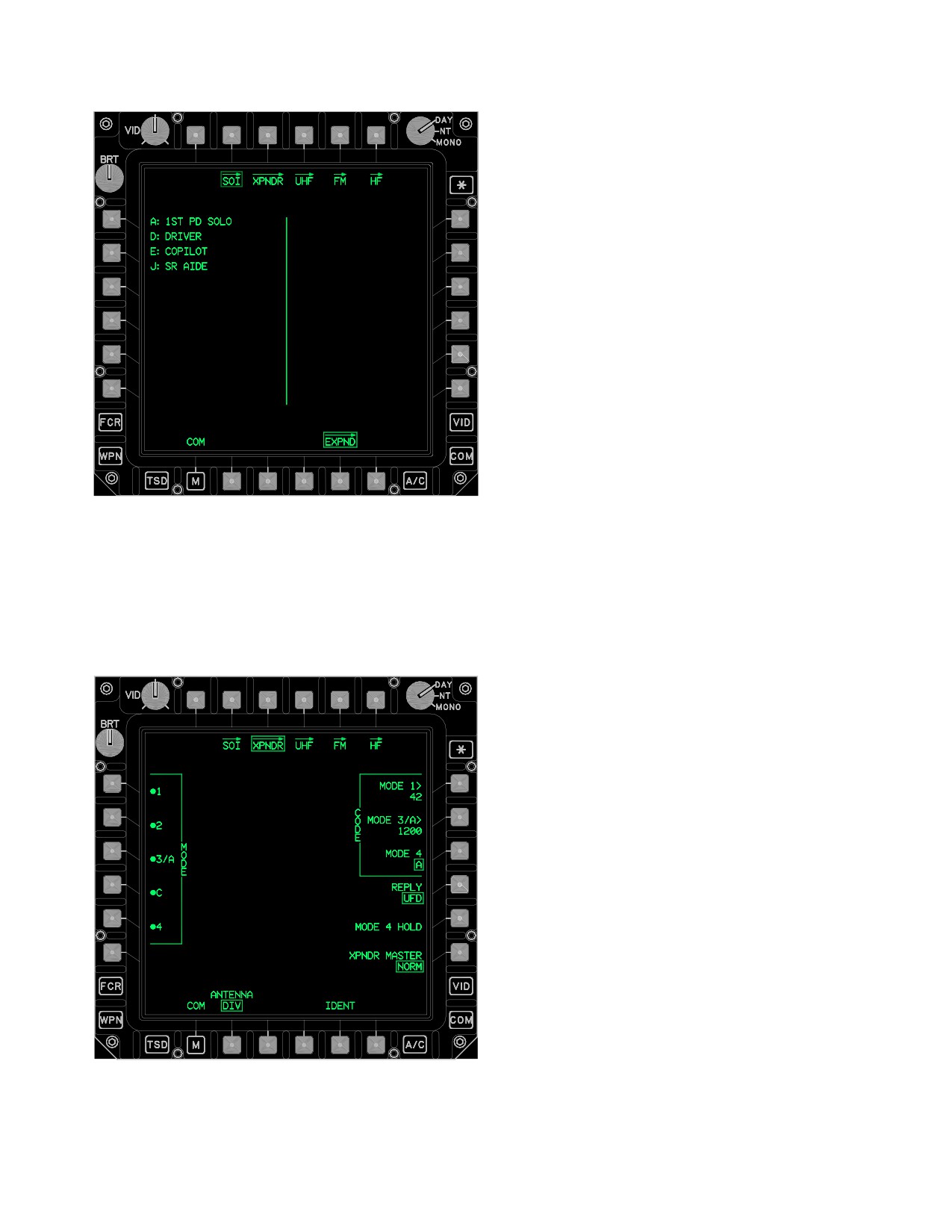
TM 1-1520-251-10
3.53AM.1 EXPND Page Button. The EXPND button
displays the EXPND page (para 3.53AL). The XPNDR
page contains the following unique buttons:
• L1
MODE 1 button
• L2
MODE 2 button
• L3
MODE 3/A button
• L4
MODE C button
• L5
MODE 4 button
• R1
CODE Mode 1 button
• R2
CODE Mode 3/A button
• R3
CODE Mode 4 button
• R4
REPLY button
• R5
MODE 4 HOLD button
• R6
XPNDR MASTER button
• B2
ANTENNA button
• B5
IDENT button
3.53AM.2 MODE 1 Button. The MODE 1 button en-
LBA5124
ables/disables MODE 1.
3.53AM.3 MODE 2 Button. The MODE 2 button en-
Figure 3-62AQ.
EXPND Page
ables/disables MODE 2.
3.53AM XPNDR PAGE
3.53AM.4 MODE 3/A Button. The MODE 3/A button
The XPNDR page (fig 3-62AR) provides the capability to
enables/disables Mode 3/A. When MODE 3/A button is
control transponder functions.
selected OFF, the MODE C button is automatically turned
OFF.
3.53AM.5 MODE C Button. The MODE C button en-
ables/disables the MODE C transmission. When MODE C
button is selected ON, the MODE 3/A button is automati-
cally turned ON.
3.53AM.6 MODE 4 Button. The MODE 4 button en-
ables/disables the MODE 4. The MODE 4 Code data field
on the EUFD (para 3A.16) is updated when the mode has
been changed. The Mode 4 warning is a tone which is
generated by the XPNDR in response to a Mode 4 incom-
patible code.
3.53AM.7 CODE MODE 1 Button. The CODE MODE
1 button provides the capability to change the MODE 1
code.
NOTE
• Due to the APX - 118 hardware and soft-
ware fielding plan, an interim alternative
MODE 2 entry procedure must be per-
formed (para 3.53AM.8).
LBA5125
• Mode 2 must be manually entered on the
Figure 3-62AR.
XPNDR Page
face of the APX - 100.
Use or disclosure of this information is subject to the restriction(s) on the title page of this document.
Change 4
3-66.39
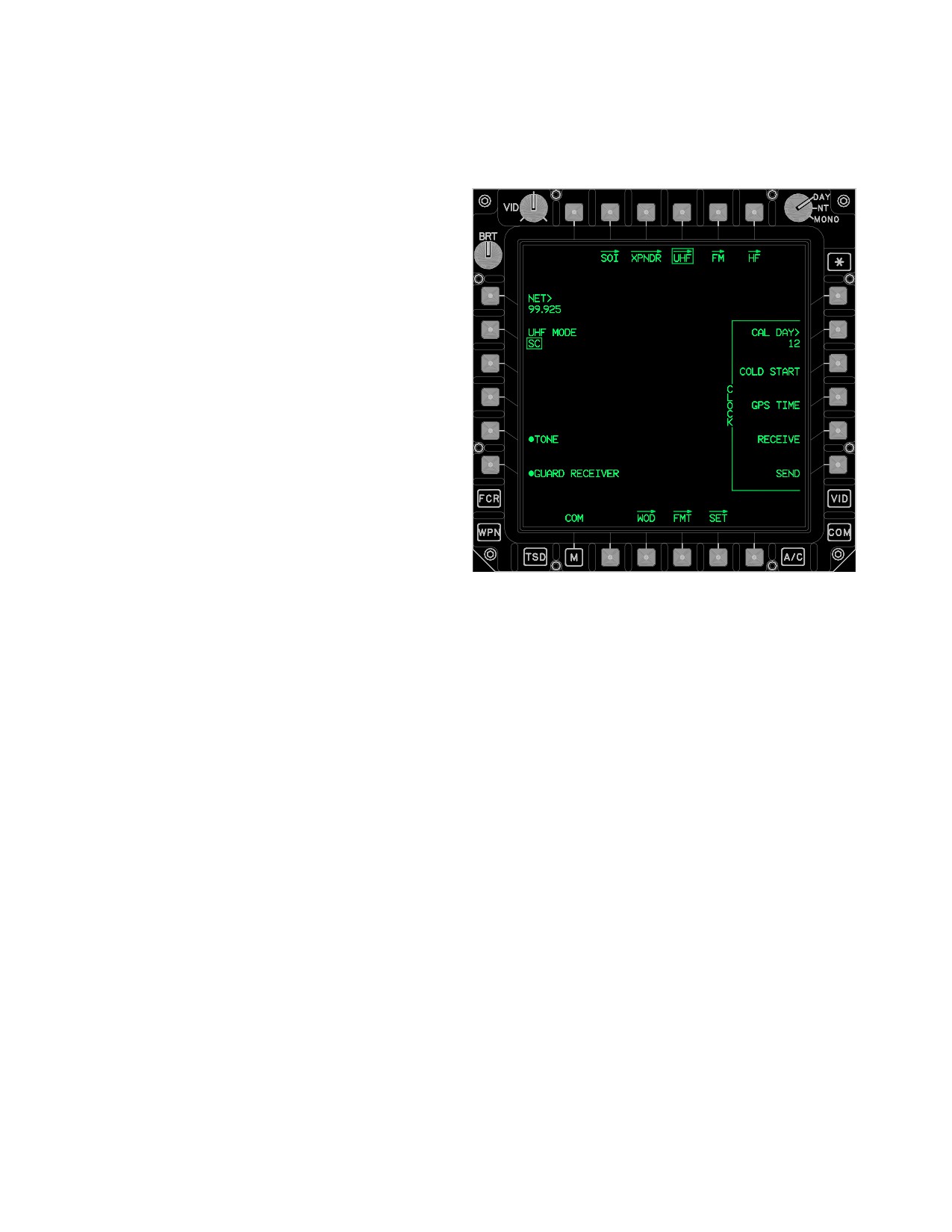
TM 1-1520-251-10
3.53AM.8 APX - 118 CODE MODE 2 Entry.
3.53AN UHF PAGE
1. MODE 3/A - Select.
The UHF page (fig 3-62AS) provides specific controls for
the ARC - 164 UHF radio.
NOTE
If the assigned mode 2 code is not entered
within 15 seconds,
2222 will be displayed as
the current MODE 3/A code.
2. Mode 2 code - Enter “2222” followed by as-
signed mode 2 code, within 15 seconds (exam-
ple: 2222xxxx).
3.53AM.9 CODE MODE 3/A Button. The CODE
MODE 3/A button provides the capability to change the
MODE 3/A code.
3.53AM.10 CODE MODE 4 Button. The CODE MODE
4 button toggles between XPNDR code MODE 4 A and B.
The code Mode 4 data field is updated when the code has
been changed. When the APX-100 is installed, the
CODE MODE 4 button is not displayed if the KIT-1C com-
puter is not installed.
3.53AM.11 REPLY Button. The REPLY button controls
the feedback the crew will receive when the XPNDR system
responds to a Mode 4 interrogation. The button provides op-
tions of EUFD/AUDIO, EUFD, and OFF. The Mode 4 Reply
LBA5126
mode of EUFD/AUDIO, enables the capability to provide both
a EUFD advisory message and an IFF Tone when a Mode 4
Figure 3-62AS. UHF Page
interrogation is received. The transponder generates the IFF
The UHF page contains the following unique buttons:
Tone to alert the aircrew that the interrogator is not receiving
• L1
NET button
a reply from the aircraft in response to a Mode 4 interroga-
tion. This indicates the incoming interrogations are valid but
• L2
UHF MODE button
not compatible with the key currently loaded into the aircraft’s
• L5
TONE button
transponder and selected by the transponder’s code (A or B).
• L6
GUARD RECEIVER button
3.53AM.12 MODE 4 HOLD Button. Selecting the
MODE 4 HOLD button prevents erasure of the Mode 4
• R2
CAL DAY button
Codes when the aircraft is on the ground and power is re-
• R3
COLD START button
moved from the transponder system. It should be acti-
• R4
GPS TIME button
vated at least 20 seconds prior to power down. When the
APX - 100 is installed, the MODE 4 HOLD button is not
• R5
RECEIVE TIME button
displayed if the Kit-1C computer is not installed.
• R6
SEND TIME button
3.53AM.13 XPNDR MASTER Button. The XPNDR
• B3
WOD page button
MASTER button changes the transponder mode between
• B4
FMT page button
STBY (Standby) and NORM (Normal).
• B5
SET page button
3.53AM.14 ANTENNA Button. The ANTENNA button al-
lows selection of the antenna used for transmitting and re-
3.53AN.1 UHF MODE Button. The UHF MODE button
ceiving XPNDR interrogations. Options are TOP, DIV (Diver-
provides the capability to control the mode of the UHF radio.
sity) and BOT (Bottom).
Options are SC (Single Channel) and HQ (HAVE QUICK).
3.53AM.15 IDENT Button. The IDENT button com-
3.53AN.2 NET Button. The NET button allows the crew to
mands the transponder to transmit Modes 1, 2, and 3/A if
enter a HAVE QUICK net number into the UHF radio. HAVE
ON. The IDENT button is not displayed if XPNDR MAS-
QUICK net numbers allow multiple station pairs to operate si-
TER button is in STBY mode or if Modes 1, 2, and 3/A are
multaneously using the same TOD (Time of Day) and WOD
all OFF, regardless of the XPNDR MASTER mode.
(Word of Day) without interference.
Use or disclosure of this information is subject to the restriction(s) on the title page of this document.
3-66.40
Change 3
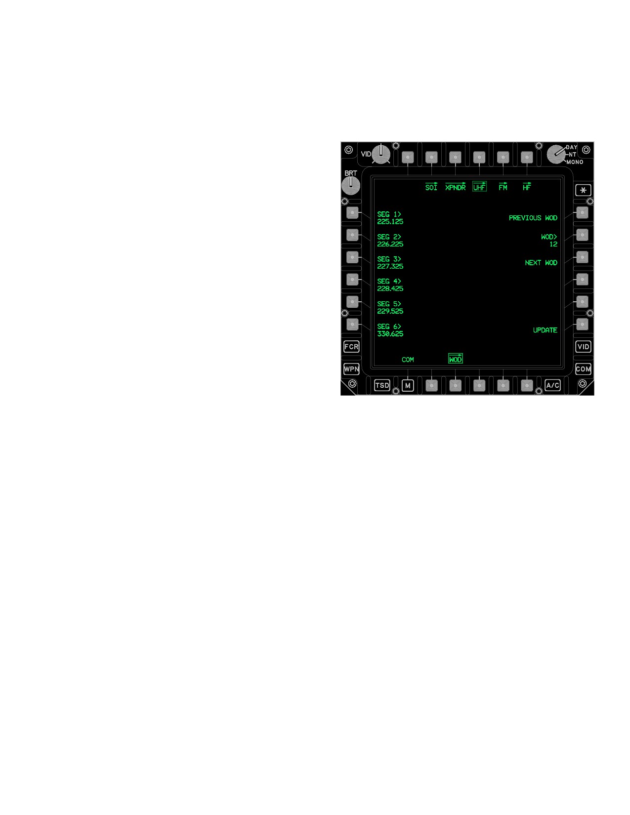
TM 1-1520-251-10
3.53AN.3 TONE Button. The TONE button allows the
3.53AO UHF WOD PAGE
crew to enable/disable the HAVE QUICK tones in the UHF
The UHF WOD page (fig 3-62AT) allows the crew to
radio.
manually enter and load WOD and WOD Segments into
the UHF radio.
3.53AN.4 GUARD RECEIVER Button. The GUARD
RECEIVER button enables/disables the UHF radio’s
monitoring of the guard frequency.
3.53AN.5 CAL DAY Button. The CAL DAY button pro-
vides the capability to change the Calendar Day in the
UHF radio. The Calendar Day is the internal date utilized
by the UHF radio. When the Calendar Day and a WOD
match in the UHF radio, the associated segments become
active, allowing HAVE QUICK communications.
3.53AN.6 COLD START Button. The COLD START but-
ton activates the Emergency Cold Start of the UHF radio’s in-
ternal clock. This will reset and start the UHF radio’s internal
clock at zero hundred hours. The COLD START button is
used when there is no other TOD available and a reference
time is required. The COLD START button is barriered when
the UHF radio is in HAVE QUICK mode.
3.53AN.7 GPS TIME Button. The GPS TIME button
causes the current time from the EGI to be loaded into the
UHF radio’s internal clock. The GPS TIME button is barri-
ered when the UHF radio is in HAVE QUICK mode.
LBA5127
NOTE
Figure 3-62AT. UHF WOD Page
Notify the other crewmember when initiating
The UHF WOD page contains the following unique buttons:
the UHF RECEIVE button, to prevent inad-
• R6
UPDATE button
vertent termination of reception.
•
L1 - L6
SEG (1 - 6) (segment) buttons
• B4
CLEAR button
3.53AN.8 RECEIVE TIME Button. The RECEIVE
TIME button configures the UHF radio to TOD receive. A
3.53AO.1 UHF WOD DAY Button. Upon entry to the
tone is generated upon successful reception of time. If
UHF WOD page the UHF WOD DAY button is zeroized.
TOD is not received within 60 seconds, the UHF radio will
The UHF WOD DAY button allows entry of a WOD for a
exit the receive mode.
new set of WOD Segments. When the Calendar Day and
a WOD match in the UHF radio, the associated segments
3.53AN.9 SEND TIME Button. The SEND TIME button
become active, allowing HAVE QUICK communications.
transmits the TOD. A tone in the headset sounds when
the TOD is transmitted.
3.53AO.2 UPDATE Button. The UPDATE button loads
the DAY and SEG data into the UHF radio. Upon a valid
3.53AN.10 WOD Page Button. The WOD button dis-
update into the UHF radio, a tone is generated and the
plays the UHF WOD page (para 3A.44).
WOD STATUS window is updated.
NOTE
3.53AN.11 FMT Page Button. The FMT button dis-
plays the FMT page (para 3A.45).
Deselecting the WOD page prior to selec-
tion of the update button will remove the
3.53AN.12 SET Page Button. The SET page button
segments from the segment buttons and will
displays the SET page. The page contains the UHF
replace them with question marks. Entry of
CRYPTO button and UHF CNV button which are used to
segments in one crewstation cannot be
configure the Crypto device (para 3A.46).
monitored in the opposite crewstation.
Use or disclosure of this information is subject to the restriction(s) on the title page of this document.
Change 3
3-66.41
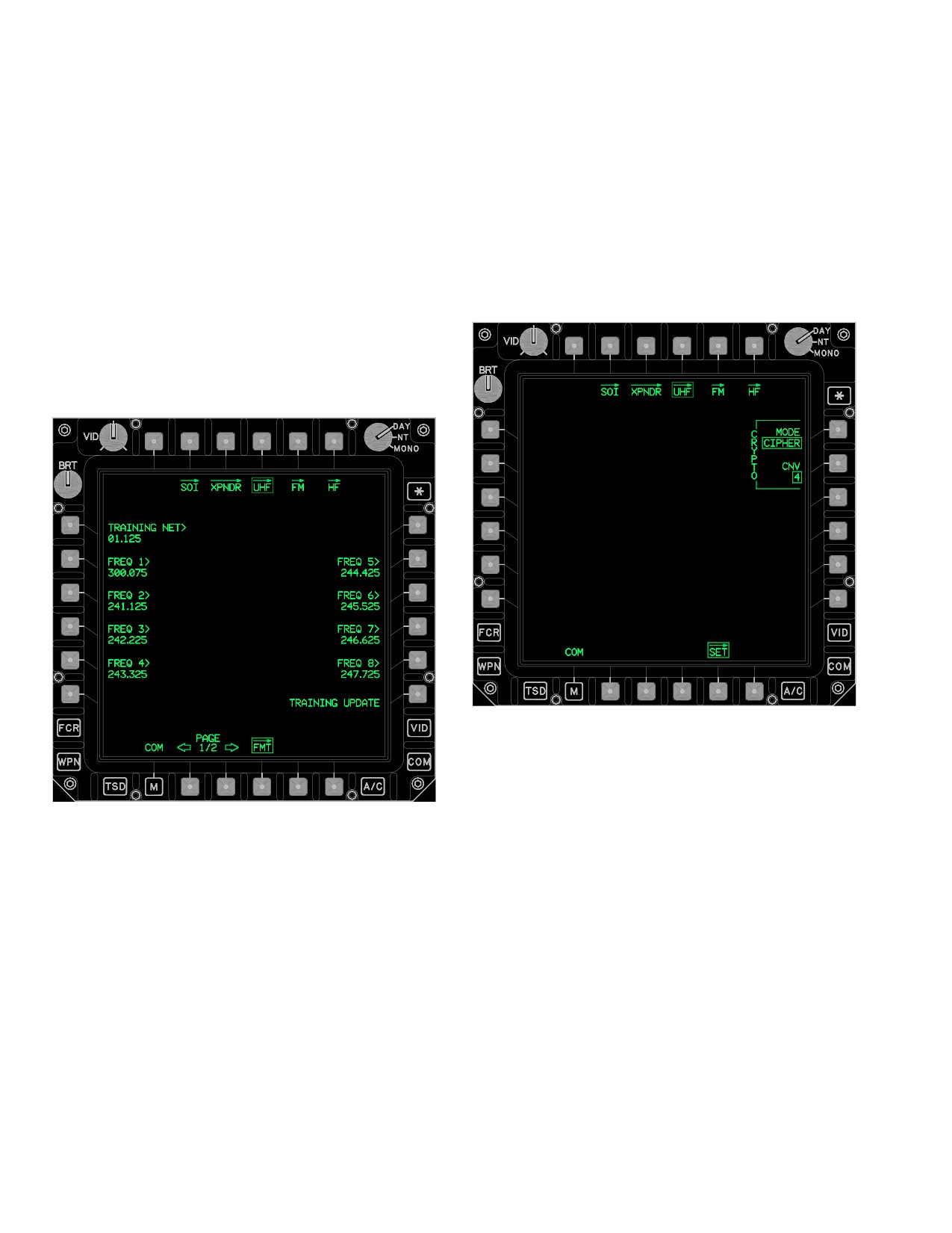
TM 1-1520-251-10
3.53AO.3 SEGment Buttons. Upon entry to the UHF
3.53AP.2 UPDATE Button. The UPDATE button loads
WOD page the SEG buttons are zeroized. The SEG but-
the UHF FMT FREQ data into the UHF radio. Upon a valid
tons allow entry of up to six WOD segments for update
update into the UHF radio, a tone is generated.
into the UHF radio. At least one WOD segment must be
3.53AP.3 PAGE Back and PAGE Forward But-
loaded into the UHF radio for HAVE QUICK operation.
tons. Allows selection between two pages of HAVE
QUICK Training Frequencies.
3.53AO.4 CLEAR Button. The CLEAR button pro-
vides the capability to clear (i.e. zeroize) the data in the
3.53AQ UHF SET PAGE
DAY and SEG buttons.
The UHF SET page (fig 3-62AV) contains the CRYPTO
MODE and CRYPTO CNV buttons for the UHF radio.
3.53AP UHF FMT PAGE
The UHF FMT page (fig 3-62AU) contains the HAVE
QUICK Training Frequencies which can be entered or
modified and then loaded into the UHF radio.
LBA5129
Figure 3-62AV. UHF SET Page
The UHF SET page contains the following unique buttons:
LBA5128
• L2
CRYPTO MODE button
• L6
CRYPTO CNV button
Figure 3-62AU. UHF FMT Page
3.53AQ.1 CRYPTO MODE Button. The CRYPTO
MODE button controls the operation of the KY - 58. The
button provides options of CIPHER, PLAIN, and RE-
The UHF FMT page contains the following unique buttons:
CEIVE.
• L2 - L5
FREQ buttons
3.53AQ.2 CRYPTO CNV Button. The CRYPTO CNV
• L6
UPDATE button
button provides the capability to change the UHF crypto
net variable with options of 1 through 6.
• R2 - R5
FREQ buttons
• B2
PAGE Back button
3.53AR FM PAGE
• B3
PAGE Forward button
The FM page (fig 3-62AW) provides the capability to con-
3.53AP.1 FREQ Buttons. The FREQ buttons provide
trol the FM radios and their FH modes. The radio control
the capability to enter or modify the 16 HAVE QUICK
buttons on the FM page are only displayed if the radio is
Training Frequencies.
installed.
Use or disclosure of this information is subject to the restriction(s) on the title page of this document.
3-66.42
Change 3
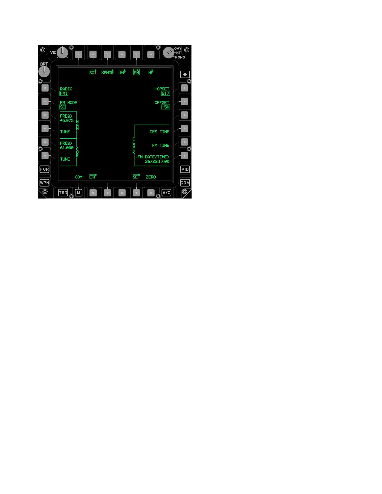
TM 1-1520-251-10
3.53AR.2 FM MODE Button. The FM Mode button
provides the capability to control the mode of the selected
radio. The button provides options of FM SC, FM FH, and
FM FH/M (Frequency Hopping/Master). SC mode allows
access to the ERF Page. FH mode allows access to the
ERF Receive Page. FH/M mode allows access to the ERF
Send Page.
3.53AR.3 MAN FREQ Button. The MAN FREQ button
provides the capability to change the Manual frequency of
the selected radio.
3.53AR.4 MAN TUNE Button. The MAN TUNE button
provides the capability to tune the radio to the frequency
that is displayed within the MAN FREQ window.
3.53AR.5 CUE FREQ Button. The CUE FREQ button
provides the capability to change the Cue frequency of the
selected radio.
LBA5130
3.53AS.6 CUE TUNE Button. The CUE TUNE button
provides the capability to tune the radio to the frequency
that is displayed within the CUE FREQ window.
Figure
3-62AW.
FM Page - SC MODE
3.53AR.7 HOPSET Button. The HOPSET button pro-
vides seven options that include the six HOPSET buttons
The FM page contains the following unique buttons:
and the MAN button. The hopset ID selected determines
the radio FH characteristics (hopping rate, frequencies,
• L1
RADIO button
and frequency order).
• L2
FM 1 MODE or FM 2 MODE button
3.53AR.8 OFFSET Button. The OFFSET button pro-
• L3
MAN FREQ button
vides the capability to control the offset ( - 10K, - 5K, 0,
• L4
MAN TUNE button
+5K, +10K) from the single channel FM frequency. The
OFFSET button is only displayed when the FM1 MODE or
• L5
CUE FREQ button
FM 2 MODE is set to SC.
• L6
CUE TUNE button
• R1
HOPSET button
3.53AS.9 LATE NET Button. The LATE NET button is
used to synchronize to an operational net whose TOD is
• R2
OFFSET button
not within the 4 second (plus/minus) frequency hopping
• R3
LATE NET button
communication window. The late net function may only be
used if the two net TODs are within 1 minute (plus/minus)
• R4
CLOCK GPS TIME button
of each other. This button is only displayed when the SINC
• R5
CLOCK FM TIME button
mode is FH.
• R6
CLOCK FM DATE/TIME button
3.53AR.10 CLOCK GPS TIME Button. The GPS TIME
• B2
ERF page button
button causes the current time from the EGI to be loaded
• B5
SET page button
into the radio and extracts that time from the selected ra-
dio and displays the data within the DATE/TIME button.
• B6
ZERO button
3.53AR.1 FM RADIO Button. The RADIO button pro-
3.53AR.11 CLOCK FM TIME Button. The FM TIME
vides the capability to toggle the display between the FM1
button extracts the current time from the selected radio
and the FM2 radio controls.
and displays the data within the DATE/TIME button.
Use or disclosure of this information is subject to the restriction(s) on the title page of this document.
Change 3
3-66.43
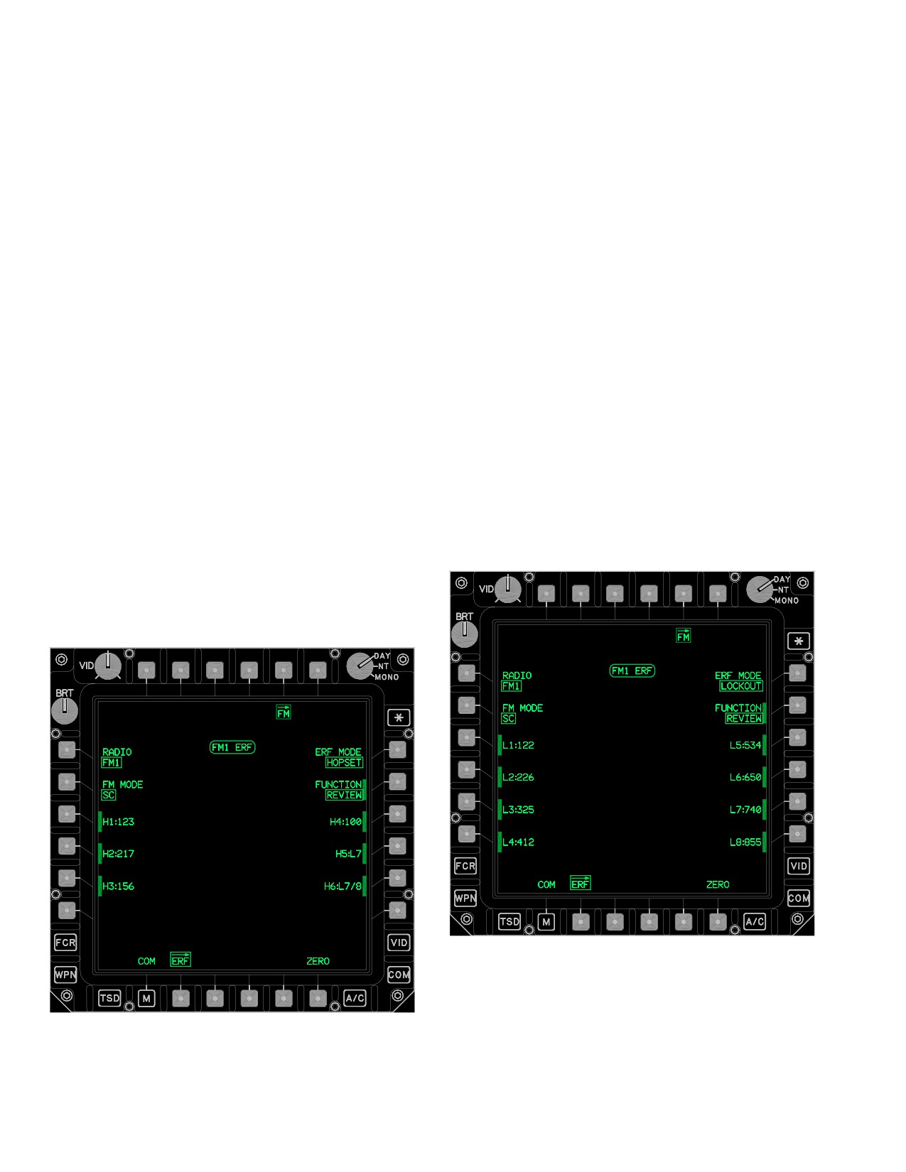
TM 1-1520-251-10
3.53AR.12 CLOCK FM DATE/TIME Button. The FM
The ERF page contains the following unique buttons:
DATE/TIME button provides the capability to change the
date and time currently loaded into the selected radio.
This data is displayed for 1 minute, then is considered
• T3
RECEIVE OR SEND button
stale.
• T4
STORE button
3.53AR.13 ERF Page Button. Selecting the ERF page
button will display the ERF page. The ERF page provides
• L1
RADIO mode button
the operator the capability to manage hopsets and lockout
sets (para 3A.48).
• L2
FM MODE button
3.53AR.14 SET Page Button. The SET page button
• L3-L6
Hopset/Lockout buttons
displays the FM SET page, which contains the POWER
button, the CRYPTO button and the CNV button.
• R1
ERF MODE button
3.53AR.15 ZERO Button. The ZERO button provides
• R2
FUNCTION button
the capability to zeroize the FM radio.
• R3-R6
Hopset/Lockout buttons
3.53AR.16 ERF RECEIVE Window. The white ERF
RECEIVE window will display on the FM ERF, and ERF
• B4
CLEAR button
SEND pages whenever the ERF RECEIVE button on the
ERF RECEIVE page is left selected for receipt of multiple
• B6
ZERO button
ERFs.
3.53AS FM ERF PAGE
The FM ERF page (figs 3-62AX and 3-62AY ) provides the
capability to manage Hopsets and Lockout sets data. The
FM ERF page incorporates three distinct modes of opera-
tion (para 3A.48.5).
LBA5136
LBA5135
Figure 3-62AX. FM ERF Page - Hopset Mode
Figure 3-62AY. FM ERF Page - Lockout Mode
Use or disclosure of this information is subject to the restriction(s) on the title page of this document.
3-66.44
Change 3
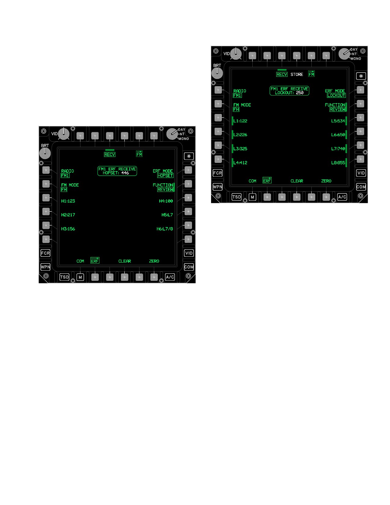
TM 1-1520-251-10
3.53AS.1 RECEIVE Button. The RECEIVE button (figs
3-62AZ and 3-62BA) provides the capability to command
the radio to the ERF receive mode. The radio remains in
the ERF receive mode to receive multiple ERFs for 5 min-
utes unless the RECEIVE button is manually deselected
or automatically deselected when a confirmed CLEAR is
performed. When a hopset or lockout set is received, this
button will be barriered until the Hopset or Lockout is ei-
ther cleared or stored (fig 3-62AZ). The RECEIVE button
is only available when the FM MODE button set to FH.
LBA5138
Figure 3-62BA. FM ERF RECEIVE Page - Lockout
Received
353AS.2 SEND Button. The SEND button (fig 3-62BB)
commands the radio to transmit the hopset or lockout ID
displayed within the FM ERF status window. This button is
only displayed when an H or L button is selected while the
LBA5137
FUNCTION button is set to REVIEW. The SEND button is
Figure 3-62AZ. FM ERF RECEIVE Page - Hopset
displayed in white and is only available when the FM
Received
MODE button set to FH/M.
Use or disclosure of this information is subject to the restriction(s) on the title page of this document.
Change 3
3-66.45
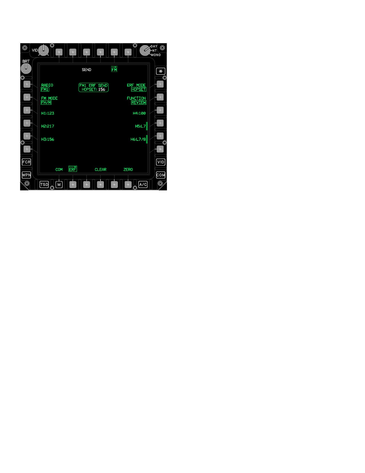
TM 1-1520-251-10
b. In Frequency Hopping modes, the FM radio auto-
matically changes its operating frequency at a predeter-
mined rate to reduce effects of jamming. Frequency hop-
ping mode allows the reception of hopset and lockout set
frequencies from other FM radios via the ERF function.
The FM radio generates the FM Load - Receiving ERF
tones when hopsets or lockout sets are received by the
radio.
c. Frequency Hopping Master mode is similar to Fre-
quency Hopping mode. However, the radio operating in
Frequency Hopping Master mode has additional capabili-
ties to allow it to be used by the frequency hopping net
controller. When operating as the Frequency Hopping
Master, the FM radio specifies the timing of all others in
the frequency hopping net. Frequency hopping master
mode allows the transmission of hopset and lockout set
frequencies to other FM radios via the ERF function.
3.53AS.6 ERF MODE Button. The ERF MODE button
operates in two modes: HOPSET and LOCKOUT. The
LBA5139
HOPSET mode configures the system for the reception of
hopsets. The LOCKOUT mode configures for the recep-
Figure
3-62BB.
ERF Page - FH/M Mode, ERF SEND
tion of lockout sets.
HOPSET Displayed
3.53AS.7 FUNCTION Button. The FUNCTION button
3.53AS.3 STORE Button. The STORE button is only
provides the capability to select REVIEW and DELETE for
displayed when a valid lockout has been received into the
hopsets and lockouts and COPY functions for hopsets.
holding memory buffer as displayed in the FM ERF status
window. The STORE button is displayed in white and is
3.53AS.8 Hopset (H) Buttons.
only available when the FM MODE button set to FH.
a. FM MODE FH. When receiving HOPSETS, se-
3.53AS.4 RADIO Button. The RADIO button config-
lecting one of the ERF HOPSET buttons (fig 3-62AZ)
ures the FM ERF page to present controls for either the
stores the hopset that is displayed within the RECEIVE
FM1 or FM2 radio.
hopset window to that button.
3.53AS.5 FM MODE Button. The FM MODE button
controls the ECCM mode of the selected FM radio:
b. FM MODE FH/M. When sending the ERF HOP-
SET buttons (fig 3-62BB) provide the capability to select a
• Single Channel
hopset to be transmitted through the ERF process. The
• Frequency Hopping
current hopset to be sent is displayed in the SEND HOP-
SET window and an intermittent beep will be heard until
• Frequency Hopping Master
the hopset is sent or cleared.
a. In Single Channel operation, the FM radio trans-
3.53AS.9 Lockout (L) Buttons.
mits and receives on a single frequency. Although not op-
erating in an ECCM mode, the radio can minimize interfer-
a. FM MODE FH. The L buttons are only selectable
ence with the use of frequency offsets. When operating in
when deleting Lockouts.
Single Channel mode, a frequency hopping net can be ini-
tialized using the manual hopping frequency. Similarly, the
CUE function is available in Single Channel mode, which
b. FM MODE FH/M. The L buttons provide the ca-
allows a single channel operator that is not currently within
pability to select a lockout to be transmitted through the
a frequency hopping net to “cue”, or contact, the frequen-
ERF process. The current lockout to be sent is displayed
cy hopping net.
in the SEND LOCKOUT window ( fig 3-62BC).
Use or disclosure of this information is subject to the restriction(s) on the title page of this document.
3-66.46
Change 3
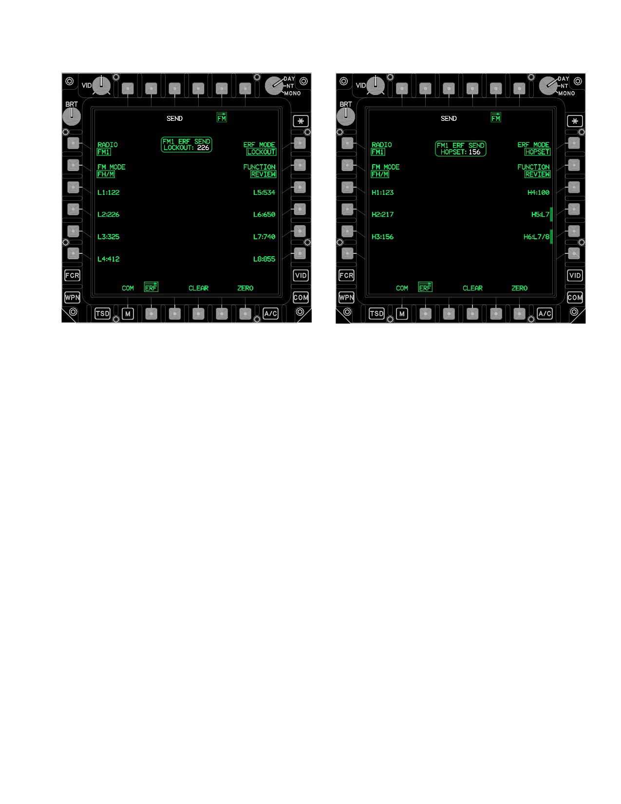
TM 1-1520-251-10
LBA5140
LBA5141
Figure 3-62BD. ERF Page - SEND HOPSET
Figure 3-62BC. FM ERF Page - SEND Lockout
NOTE
A YES/NO confirmation will only display
when the CLEAR button is used to clear a
3.53AS.10 CLEAR Button.
received HOPSET or LOCKOUT.
3.53AS.11 RECEIVE HOPSET Window. The RE-
a. FM MODE FH. The CLEAR button (fig 3-62AZ)
CEIVED HOPSET window (fig 3-62AZ) is displayed when
provides the capability to clear a HOPSET or LOCKOUT
the system has received a valid HOPSET. The HOPSET
from the holding memory buffer. The CLEAR button will
will be displayed in white.
display upon receipt of a HOPSET or LOCKOUT and
when in COPY mode.
3.53AS.12 RECEIVE LOCKOUT Window. The RE-
CEIVE LOCKOUT window (fig 3-62BA) is displayed when
the system has received a valid LOCKOUT.
b. FM MODE FH/M. The CLEAR button (fig
3-62BD) clears the hopset or lockout that was selected for
3.53AS.13 ERF SEND HOPSET Window. The ERF
sending. The CLEAR button removes the SEND button
SEND HOPSET window (fig 3-62BD) displays the hopset
and itself (fig 3-62BF). The CLEAR button will display
data that is to be transmitted through the ERF process
when in COPY or EDIT modes.
with the selection of the SEND button.
Use or disclosure of this information is subject to the restriction(s) on the title page of this document.
Change 3
3-66.47
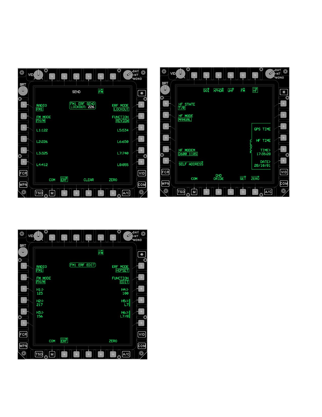
TM 1-1520-251-10
3.53AS.14 ERF SEND LOCKOUT Window. The ERF
3.53AT HF PAGE
SEND LOCKOUT window (fig 3-62BE) displays the lock-
The HF page (fig 3-62BG) provides specific controls for
out data that is to be transmitted through the ERF process
the ARC - 220 HF radio.
with the selection of the SEND button.
LBA5142
LBA5144
Figure 3-62BG. HF Page - MANUAL Mode
Figure
3-62BE.
ERF Page - SEND LOCKOUT
The HF page contains the following unique buttons when
in MANUAL mode:
• L1
HF STATE button
• L2
HF MODE button
• L5
HF MODEM button
• L6
SELF ADDRESS page button
• R3
CLOCK GPS TIME button
• R4
CLOCK HF TIME DISPLAY button
• R5
CLOCK TIME button
• R6
CLOCK DATE entry button
• B3
GND ORIDE button
• B5
SET page button
• B6
ZERO page button
3.53AT.1 HF STATE Button. The HF STATE button
provides the capability to set the HF radio to STBY
(Standby), SILENT, or T/R (Transmit/Receive). Standby is
the power up mode of the HF radio. Silent mode allows
reception of voice and data, but not automated transmis-
sions. Manual transmissions of voice (using PTT switch)
LBA5143
and data (using HF SEND buttons) are still possible while
in Silent mode. Normal HF radio operations occur when in
Figure
3-62BF. ERF Page - HOPSET Edit
the Transmit/Receive mode.
Use or disclosure of this information is subject to the restriction(s) on the title page of this document.
3-66.48
Change 3
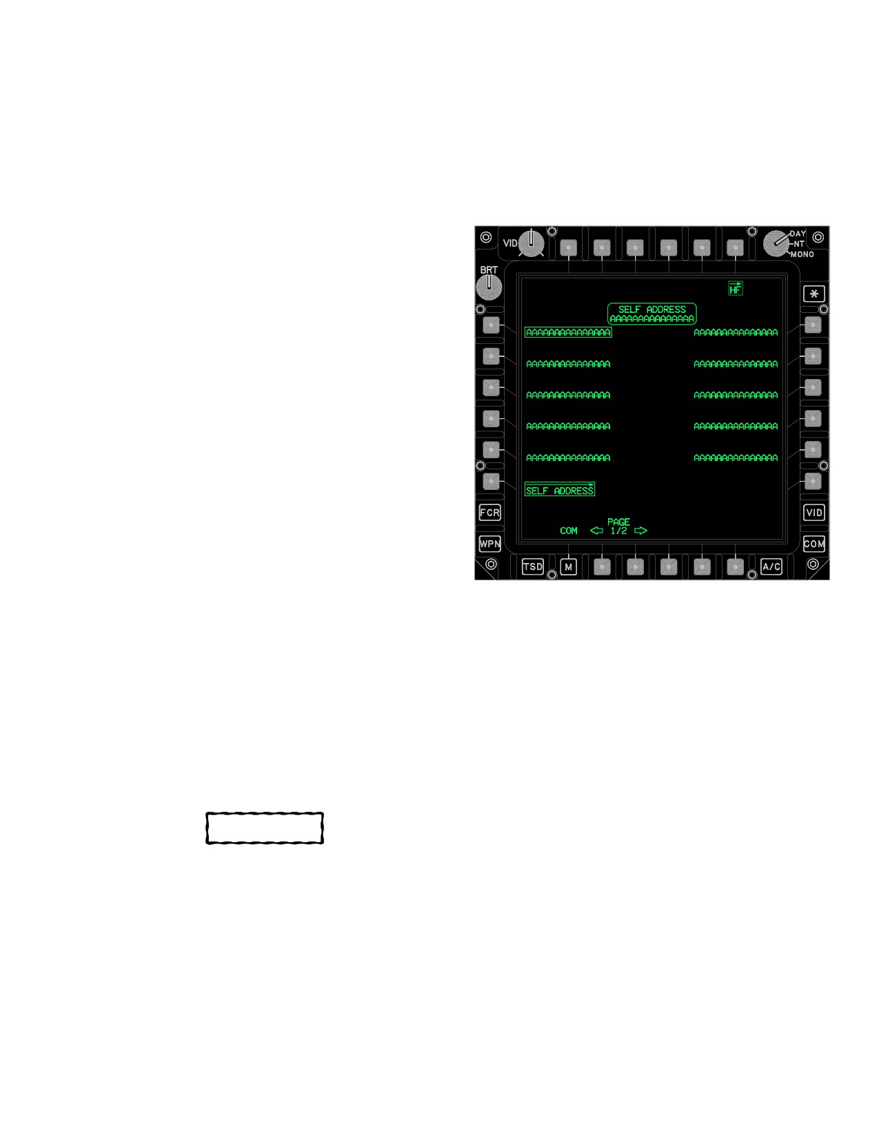
TM 1-1520-251-10
3.53AT.2 HF MODE Button. The HF MODE button pro-
3.53AT11 ZERO Button. The ZERO button displays
vides the capability to configure the HF radio into MANU-
the HF ZERO page (para 3A.59).
AL, PRESET, ALE (Automatic Link Establishment),
3.53AU HF SELF ADDRESS PAGE
ECCM (Electronic Counter Counter Measure Frequency
Hop), or EMERGENCY. Manual mode allows for tuning of
The HF SELF ADDRESS page (fig 3-62BH) provides up
the HF radio from the MAN page. Preset mode provides
to 20 non - modifiable self address options for selection.
up to 20 preprogrammed frequency channels to tune the
HF radio. ALE mode provides up to 20 preprogrammed
nets. And ECCM mode provides up to 12 preprogrammed
nets to establish links with various callers. Emergency
mode is a preprogrammed configuration of the radio for
use in an emergency.
3.53AT.3 HF MODEM Button. The HF MODEM button
provides the capability to select from up to 12 prepro-
grammed modem configurations for data communica-
tions.
3.53AT.4 SELF ADDRESS Page Button. The SELF
ADDRESS button displays the HF SELF ADDRESS page
(para 3A.50).
3.53AT.5 CLOCK GPS TIME Button. The CLOCK
GPS TIME button causes the current time from the EGI to
be loaded into the HF radio’s internal clock. Selection of
this button changes the HF STATE to STBY.
3.53AT.6 CLOCK HF TIME Display Button. The
LBA5145
CLOCK HF TIME display button provides the capability to
get the current time and date from the HF radio and have
Figure 3-62BH. HF SELF ADDRESS Page
it displayed in the CLOCK TIME and DATE buttons.
The HF SELF ADDRESS page contains the following
3.53AT.7 CLOCK TIME Button. The CLOCK TIME
unique buttons:
button provides the capability to view the current time in
• L1 - L5
HF self address option buttons
the HF radio or to change the time in the HF radio.
•
R1 - R5
HF self address option buttons
3.53AT.8 CLOCK DATE Button. The CLOCK DATE
• B2
PAGE Back button
button provides the capability to view the current date in
• B3
PAGE Forward button
the HF radio or to change the date in the HF radio.
3.53AU.1 HF Self Address Option Buttons. The HF
self address option buttons provide the capability to select
from up to 20 non - modifiable self addresses in the HF ra-
CAUTION
dio.
There are no UFD/EUFD indications
3.53AU.2 PAGE Back and Forward Buttons. Allows
when the HF radio override is selected.
selection between two pages of HF self addresses.
3.53AU.3 HF SELF ADDRESS Status Window. The
3.53AT.9 GND ORIDE Button. The GND ORIDE but-
HF SELF ADDRESS status window displays the current
ton provides the capability when selected, to override the
self address selected in the HF radio.
safety inhibits, in order to transmit on the HF radio while
the aircraft is on the ground.
3.53AV HF PAGE - PRESET MODE
3.53AT.10 SET Button. The SET button displays the
The HF PRESET Mode (fig 3-62BI) provides specific con-
HF SET page (para 3A.58).
trols and status when the HF radio is in the Preset mode.
Use or disclosure of this information is subject to the restriction(s) on the title page of this document.
Change 3
3-66.49
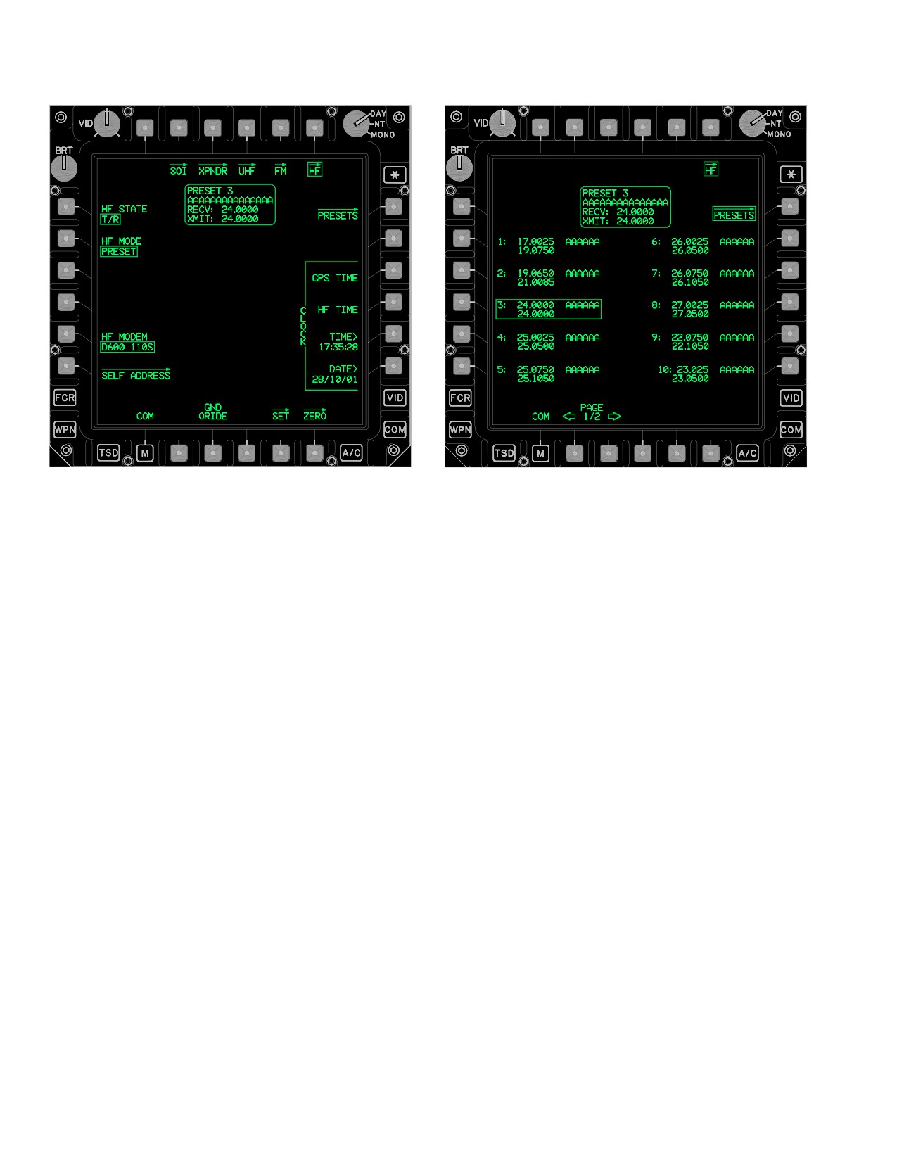
TM 1-1520-251-10
LBA - 5146
LBA - 5147
Figure 3-62BJ. HF PRESETS Page
Figure 3-62BI. HF Page - PRESET Mode
The HF page contains the following unique button when in
The HF PRESETS page contains the following unique
PRESET mode:
buttons:
• R1
PRESETS page button
• L2 - L6
HF preset channel buttons
3.53AV.1 PRESETS Page Button. The PRESET but-
• R2 - R6
HF preset channel buttons
ton displays the HF PRESETS page (para 3A.52).
• B2
PAGE Back button
3.53AV.2 HF PRESET Status Window. The HF PRE-
• B3
PAGE Forward button
SET status window displays the current preset channel
3.53AW.1 HF Preset Channel Buttons. The HF PRE-
number, name, and receive/transmit frequencies when
SET CHANNEL buttons provide the capability to select
the HF radio is in Preset mode.
from up to 20 non - modifiable preset channels in the HF
3.53AW HF PRESETS PAGE
radio.
The HF PRESETS page (fig 3-62BJ) provides up to 20
3.53AW.2 PAGE Back and PAGE Forward But-
non - modifiable preset channels for selection, when the
tons. Allows selection between two pages of HF preset
HF radio is in the Preset mode.
channels.
Use or disclosure of this information is subject to the restriction(s) on the title page of this document.
3-66.50
Change 3
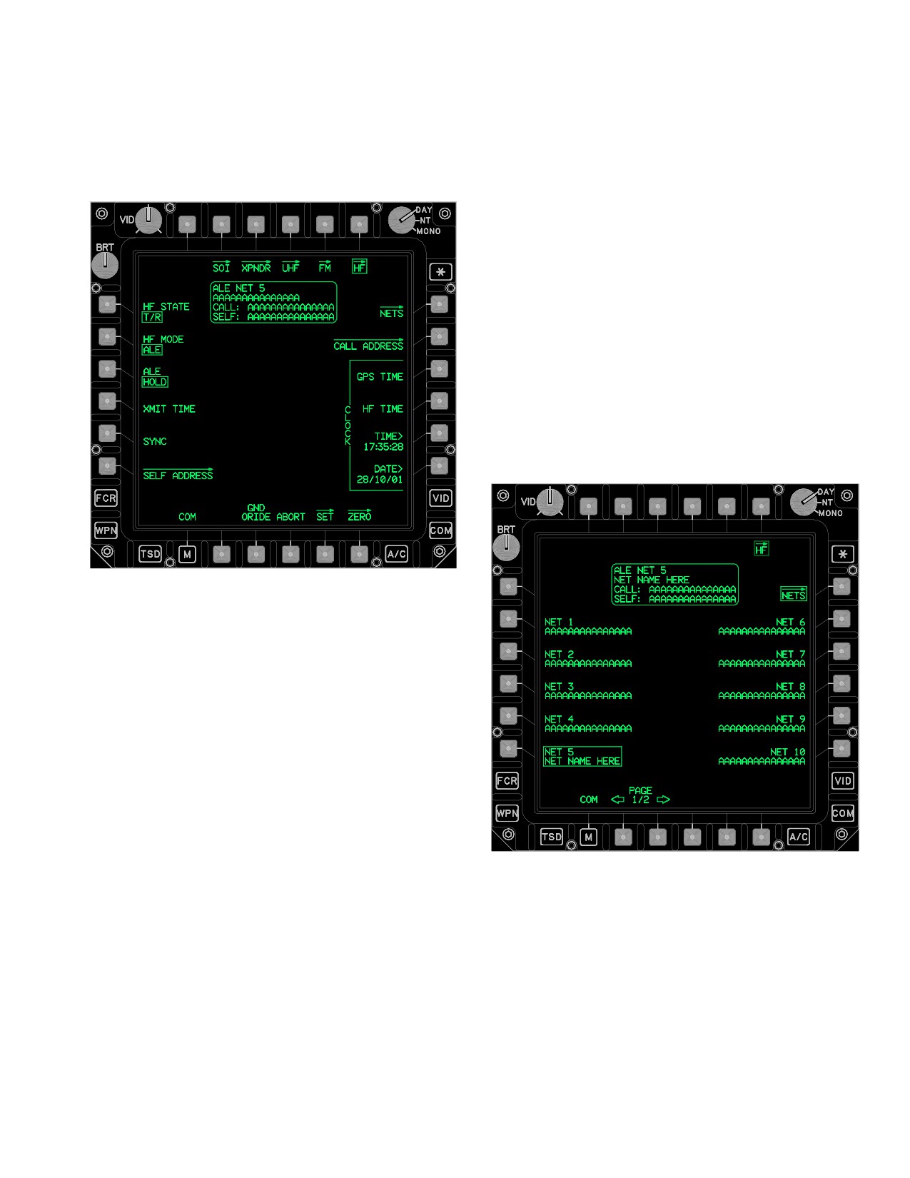
TM 1-1520-251-10
3.53AX HF PAGE - ALE MODE
3.53AX.4 NETS Page Button. The NETS page button
displays the HF ALE NETS page (para 3A.54).
The HF ALE Mode (fig 3-62BK) provides specific controls
and status when the HF radio is in the ALE mode.
3.53AX.5 CALL ADDRESS Page Button. The CALL
ADDRESS page button displays the HF CALL ADDRESS
page (para 3A.57).
3.53AX.6 ABORT Button. The ALE ABORT button
provides the capability to abort any ALE function in prog-
ress.
3.53AX.7 ALE Status Window. The ALE status win-
dow displays the current ALE net number, name, call ad-
dress, and self address, when the HF radio is in ALE
mode.
3.53AY HF ALE NETS PAGE
The HF ALE NETS page (fig 3-62BL) provides up to 20
non - modifiable ALE nets for selection.
LBA5148
Figure 3-62BK. HF Page - ALE Mode
The HF page contains the following unique buttons when
in ALE mode:
• L3
ALE HOLD/SCAN button
• L4
XMIT TIME button
• L5
SYNC button
• R1
NETS page button
• R2
CALL ADDRESS page button
• B4
ABORT button
LBA5149
3.53AX.1 ALE HOLD/SCAN Button. The ALE HOLD/
Figure 3-62BL. HF ALE NETS Page
SCAN button toggles between HOLD and SCAN.
The HF ALE NETS page contains the following unique
3.53AX.2 XMIT TIME Button. The XMIT TIME button
buttons:
provides the capability to send the HF radio’s current time
over the current ALE net.
• R2 - R6
NET (1 - 5) option buttons
• L2 - L6
NET (6 - 10) option buttons
3.53AX.3 SYNC Button. The SYNC button provides
• B2
PAGE Back button
the capability to synchronize with others on the current
ALE net.
• B3
PAGE Forward button
Use or disclosure of this information is subject to the restriction(s) on the title page of this document.
Change 3
3-66.51
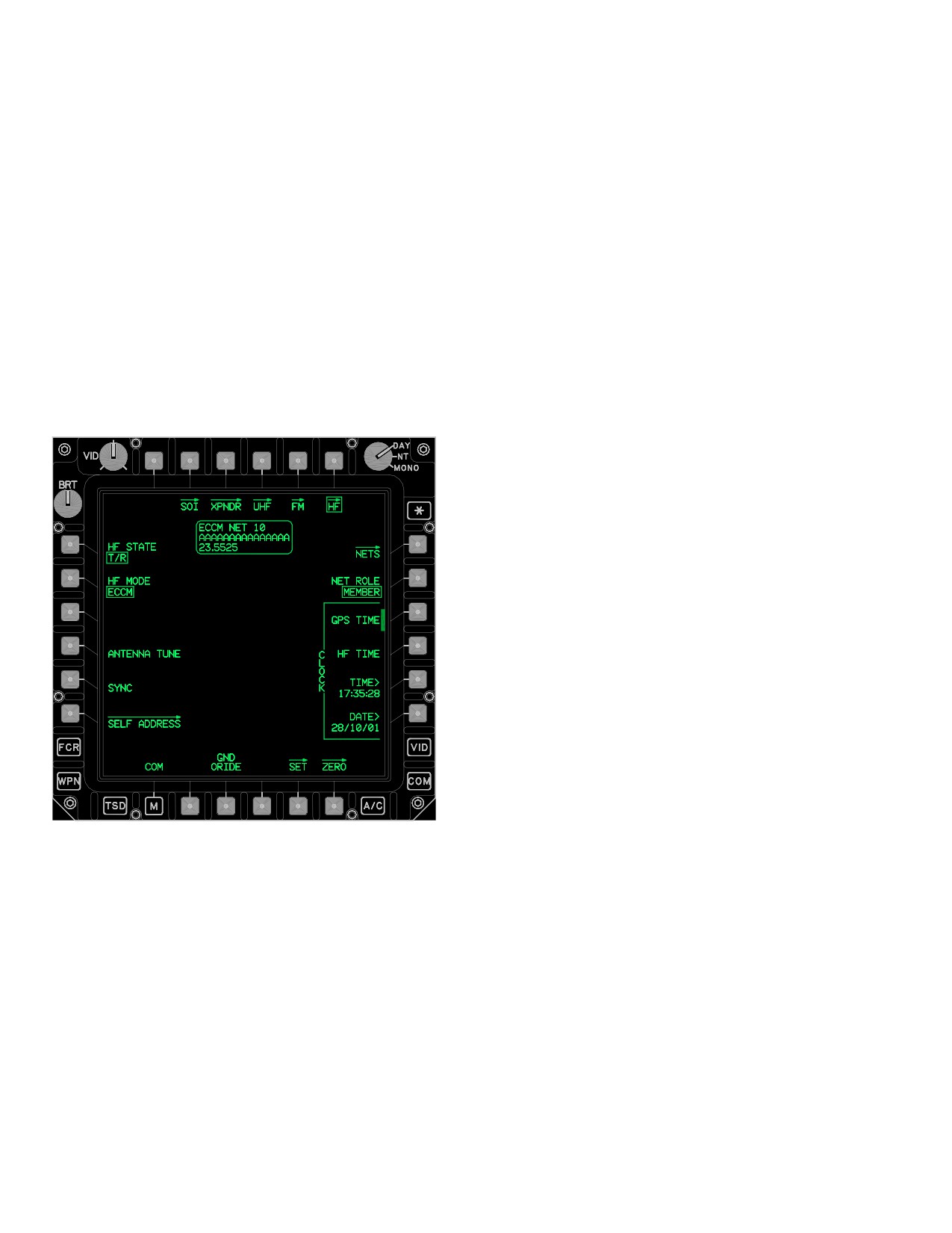
TM 1-1520-251-10
3.53AY.1 NET (1 - 10) Option Buttons. Option buttons
The HF ECCM Mode page contains the following unique
provide the capability to select from up to 20 non - modifi-
buttons:
able ALE nets in the HF radio.
•
L3
ANTENNA TUNE button
3.53AY.2 PAGE Back and PAGE Forward But-
• L4
SYNC button
tons. Allow selection between two pages of HF ALE
• R2
NET ROLE button
nets.
3.53AZ.1 ANTENNA TUNE Button. Selecting the AN-
3.53AZ HF PAGE - ECCM MODE
TENNA TUNE button initiates tuning of the ECCM scan-
set.
The HF ECCM Mode page (fig 3-62BM) provides specific
3.53AZ.2 SYNC Button. Selecting the SYNC button
controls and status when the HF radio is in the ECCM
initiates an ECCM time synchronization of the ECCM
mode. In ECCM operation the HF radio will frequency hop
scanset.
on a set of frequencies. Each radio in the net must have
the same ECCM data fill and time of day to interchange
3.53AZ.3 NET ROLE Button. The NET ROLE button
voice or data in this mode.
provides the capability to select the Net Role of the own-
ship when the HF radio is in ECCM mode. The multi - state
options are:
• MEMBER, to select Member
• ALT TIME SERVER, to select Alternate Net Time
Server
• TIME SERVER, to select Net Time Server
Member is the default role upon power - up.
3.53BA HF ECCM NETS PAGE
Selecting the ECCM NETS page button calls the ECCM
NETS page to display. The HF ECCM NETS page pro-
vides up to 12 non - modifiable ECCM nets for selection
(fig 3-62BL). The ECCM NETS page status window will
display ECCM NET with the selected number of the se-
lected net.
The HF ECCM NETS page contains the following unique
buttons:
• R2 - R6
NET (1 - 5) options button
• L2 - L6
NET (6 - 10) options button
LBA5150
• B2
PAGE Back button
Figure
3-62BM.
HF Page - ECCM Mode
• B3
PAGE Forward button
Use or disclosure of this information is subject to the restriction(s) on the title page of this document.
3-66.52
Change 3
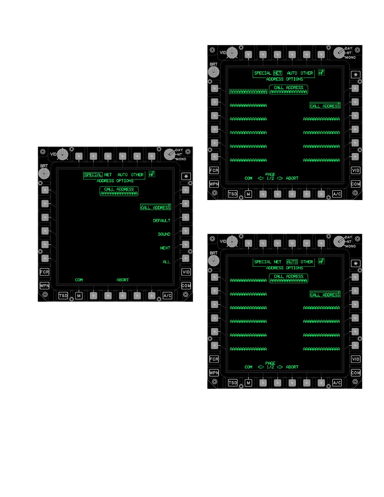
TM 1-1520-251-10
3.53BB HF CALL ADDRESS PAGE
The HF CALL ADDRESS page (fig 3-62BN, 3-62BO,
3-62BP, and 3-62BQ) provides special call address con-
trols, including up to 20 non - modifiable Star Net call ad-
dresses, up to 20 non - modifiable Auto call addresses,
and up to 100 Other call addresses for selection.
LBA5152
Figure 3-62BO. HF CALL ADDRESS Page (NET
Selected)
LBA5151
Figure 3-62BN. HF CALL ADDRESS Page
(SPECIAL Selected)
LBA5153
Figure 3-62BP. HF CALL ADDRESS Page (AUTO
Selected)
Use or disclosure of this information is subject to the restriction(s) on the title page of this document.
Change 3
3-66.53
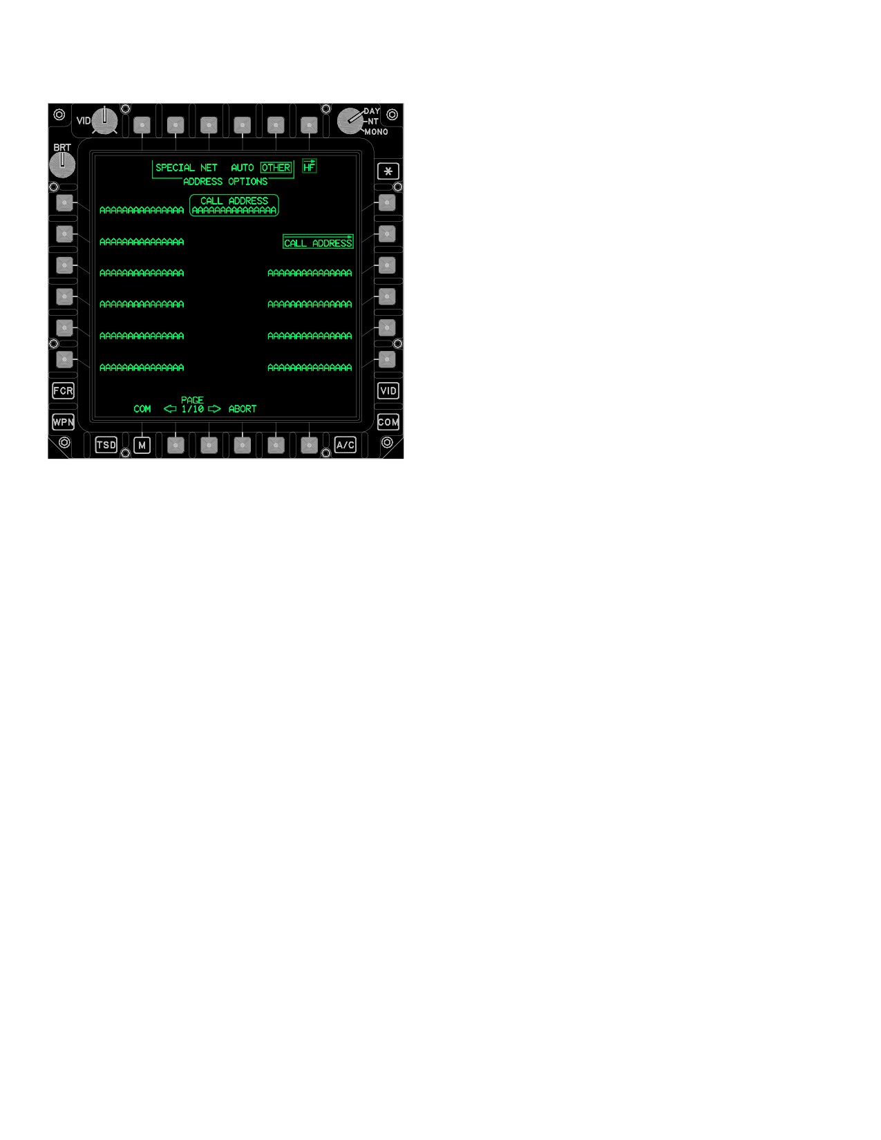
TM 1-1520-251-10
that would be considered poorer channels. This function
can be terminated prematurely by selecting the ABORT
button.
3.53BB.5 ALL Button. The ALL button sets the call
address to ALL for the current ALE net and allows a call to
all ALE stations in the network.
3.53BB.6 ABORT Button. The ABORT button pro-
vides the capability to abort any ALE function in progress.
3.53BB.7 HF CALL ADDRESS Status Window. The
HF CALL ADDRESS status window displays the current
Call Address selected in the HF radio.
The HF CALL ADDRESS page contains the following
unique buttons when NET is selected:
• L1 - L6
NET CALL ADDRESS buttons
• R3 - R6
NET CALL ADDRESS buttons
• B2
PAGE Back button
• B3
PAGE Forward button
LBA5154
3.53BB.8 NET CALL ADDRESS Buttons. The NET
CALL ADDRESS buttons provide the capability to select
Figure 3-62BQ. HF CALL ADDRESS Page (OTHER
from up to 20 non - modifiable Star Net Call Addresses in
Selected)
the HF radio.
The HF CALL ADDRESS page contains the following
3.53BB.9 PAGE Back and PAGE Forward But-
unique buttons when SPECIAL is selected:
tons. These buttons allow selection between two pages
• T2 - T5
ADDRESS OPTIONS buttons
of HF Star Net Call Addresses.
• R3
DEFAULT button
The HF CALL ADDRESS page contains the following
• R4
SOUND button
unique buttons when AUTO is selected:
• R5
NEXT button
• L1 - L6
AUTO CALL ADDRESS buttons
• R6
ALL button
• R3 - R6
AUTO CALL ADDRESS buttons
• B3
ABORT button
3.53BB.1 ADDRESS OPTIONS Buttons. The AD-
3.53BB.10 AUTO CALL ADDRESS Buttons. The
DRESS OPTIONS buttons provide the capability to select
AUTO CALL ADDRESS buttons provide the capability to
between SPECIAL, NET (Star Net), AUTO, or OTHER
select from up to 20 non - modifiable Auto Call Addresses
call address selection options.
in the HF radio.
3.53BB.2 DEFAULT Button. The DEFAULT button
The HF CALL ADDRESS page contains the following
sets the call address to the default call address for the cur-
unique buttons when OTHER is selected:
rent ALE net.
3.53BB.3 SOUND Button. The SOUND button sets
• L1 - L6
OTHER CALL ADDRESS buttons
the current call address to SOUND and initiates sounding
• R3 - R6
OTHER CALL ADDRESS buttons
on the current ALE net. This function can be terminated
prematurely by selecting the ABORT button.
3.53BB.11 OTHER CALL ADDRESS Buttons. The
3.53BB.4 NEXT Button. The NEXT button sets the last
OTHER CALL ADDRESS buttons provide the capability to
linked with call address for the current net and then tries to
select from up to 100 non - modifiable Other Call Address-
connect on channels in the ranked channel list for the net
es in the HF radio.
Use or disclosure of this information is subject to the restriction(s) on the title page of this document.
3-66.54
Change 3
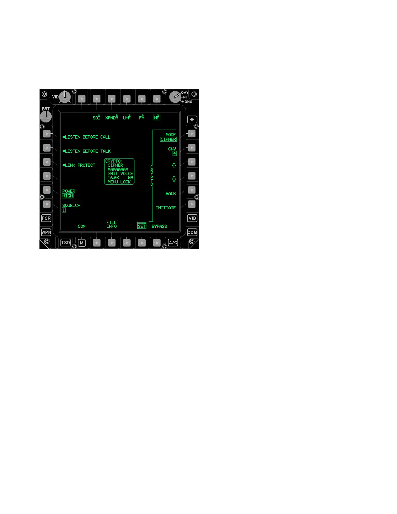
TM 1-1520-251-10
3.53BC HF SET PAGE
3.53BC.2 LISTEN BEFORE TALK Button. The LIS-
TEN BEFORE TALK button enables/disables the listen
The HF SET page (fig 3-62BR) provides on/off and ancil-
before talk function in the HF radio.
lary controls.
3.53BC.3 LINK PROTECT Button. The LINK PRO-
TECT button enables/disables ALE link protection in the
HF radio.
3.53BC.4 HF POWER Button. The HF POWER button
provides the capability to set the HF radio power output to
LOW, MEDIUM, or HIGH.
3.53BC.5 HF SQUELCH Button. The HF SQUELCH
button provides the capability to set the HF radio squelch
level to 1, 2, 3, 4, or 5, which takes affect when squelch is
enabled from the COMM Panel
3.53BC.6 HF CRYPTO MODE Button. The HF CRYP-
TO button provides the capability to control the operation
of the HF radio’s Crypto device. The button provides the
options of:
• PLAIN, for non - encrypted communication
• CIPHER (for encrypted communication)
• RECEIVE, to receive a Crypto Net Variable
through the RF link process
LBA5155
• OFFLINE, to turn off Crypto device
The Crypto data field on the EUFD is updated when the
Figure
3-62BR.
HF SET Page
mode is changed. The Crypto state is uploadable from the
Data Transfer Cartridge. Upon power up, the last Crypto
state used is restored.
The HF SET page contains the following unique buttons:
3.53BD.7 HF CRYPTO CNV Button. The HF CNV but-
• L1
LISTEN BEFORE CALL button
ton provides the capability to change the HF Crypto Net
• L2
LISTEN BEFORE TALK button
Variable. The button provides 6 (1 through 6) variable op-
• L3
LINK PROTECT button
tions. The HF CNV data field on the EUFD is updated
when the code has been modified. The HF Crypto Net
• L5
POWER button
Variable option may be set via the AMPS. Upon power up,
• L6
SQUELCH button
the last HF Crypto Net Variable option is used.
• R1
CRYPTO MODE button
3.53BC.8 HF CRYPTO UP ARROW Button. The HF
• R2
CRYPTO CNV button
CRYPTO UP ARROW button provides the capability to
• R3
CRYPTO UP ARROW button
scroll up thru the KY - 100’s menu system.
• R4
CRYPTO DOWN ARROW button
3.53BC.9 HF CRYPTO DOWN ARROW Button. The
• R5
BACK button
HF CRYPTO DOWN ARROW button provides the capa-
bility to scroll up thru the KY - 100’s menu system.
• R6
CRYPTO INITIATE button
• B3
FILL INFO button
3.53BC.10 HF CRYPTO INITIATE Button. The HF
• B6
CRYPTO BYPASS button
CRYPTO INITIATE button provides the capability to initi-
ate selections from the KY - 100 menus.
3.53BC.1 LISTEN BEFORE CALL Button. The LIS-
TEN BEFORE CALL button enables/disables the listen
3.53BC.11 BACK Button. The HF BACK button pro-
before call function in the HF radio.
vides the capability to back out of KY - 100 menus.
Use or disclosure of this information is subject to the restriction(s) on the title page of this document.
Change 3
3-66.55
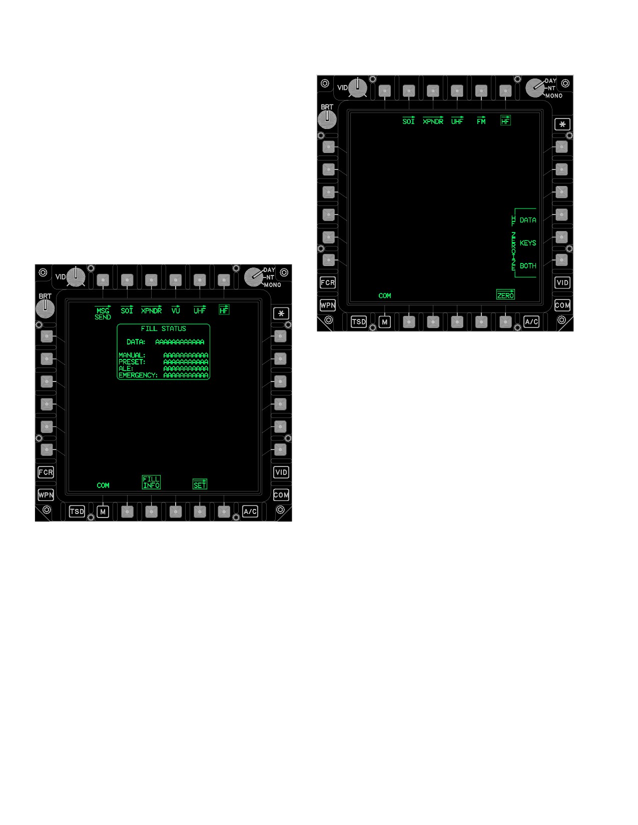
TM 1-1520-251-10
3.53BC.12 HF FILL INFO Button. Selection of the HF
FILL INFO button commands the HF FILL status window
to display.
3.53BC.13 HF CRYPTO BYPASS Button. The HF
CRYPTO BYPASS button provides the capability to by-
pass the HF radio’s crypto device in case of failure.
3.53BC.14 FILL STATUS Window. The FILL STATUS
window (fig 3-62BS) displays the fill status of data in the
HF radio. The FILL STATUS window is not available while
a fill is in progress.
LBA5157
Figure 3-62BT. HF ZERO Page
The HF ZERO page contains the following unique but-
tons:
• R4
HF ZEROIZE DATA button
• R5
HF ZEROIZE KEYS button
• R6
HF ZEROIZE BOTH button
3.53BD.1 HF ZEROIZE DATA Button. The HF ZER-
OIZE DATA button will zeroize non - key data in the HF ra-
dio. Selection of this button will prompt for a YES or NO
confirmation to initiate the zeroize.
LBA5156
3.53BD.2 HF ZEROIZE KEYS Button. The HF ZER-
OIZE KEYS button will zeroize LP1 and LP2 keys in the
Figure 3-62BS. HF SET Page (FILL INFO Selected)
HF radio. Selection of this button will prompt for a YES or
NO confirmation to initiate the zeroize.
3.53BD HF ZERO PAGE
3.53BD.3 HF ZEROIZE BOTH Button. The HF ZER-
OIZE BOTH button will zeroize all data and keys in the HF
radio. Selection of this button will prompt for a YES or NO
The HF ZERO page (fig 3-62BT) provides controls to zer-
confirmation to initiate the zeroize.
oize either data or keys in the HF radio, for diagnostic pur-
poses.
Use or disclosure of this information is subject to the restriction(s) on the title page of this document.
3-66.56
Change 2
TM 1-1520-251-10
3.53BE ARC-164 HAVE QUICK (HQ) PROCEDURES
When using the TSET segment list for
training, NET numbers are 0z.z25. The
3.53BE.1 Automatic Loading HQ Data.
suffix of 25 specifies that the TSET fre-
quency list in the radio is to be used for
NOTE
hopping. The z.z is any number 0.0 to 1.5
and designates which of the frequencies
• When using the DTU to load HQ WOD
in the list will be used to start hopping.
data into the aircraft, all HQ WOD data is
loaded.
1.
COM - Select.
• HQ FMT data must be entered manually
into the aircraft. There is no DTU upload
2.
UHF - Select.
capability. HQ FMT data is the same data
for the UHF radio.
3.
WOD - Select.
1. DTU - Select MASTER LOAD.
4.
WOD Day number - Enter
or
5.
Enter WOD Segments1 through 6.
2. DTU DATA COMMUNICATIONS - Select ALL
or MWOD.
6.
UPDATE - Press.
3.53BE.2 Manual Loading HQ Data.
7.
Repeat steps 4 through 6 as necessary until all
NOTE
WOD Segments have been entered.
• The last two digits of the first segment in
8.
WOD - Deselect.
any WOD specifies the hoprate in the FH
mode:
xxx.x00 (slowest)
9.
NET - Enter.
xxx.x25
xxx.x50
10.
CAL DAY - Enter.
xxx.x75 (fastest)
Best results for FH (secure), use hop-
11.
UHF - Deselect when complete.
rates between xxx.x00 or xxx.x25.
• The calendar day (via GPS/RECEIVE
or
TOD/CAL DAY) number specifies which
WOD segment list the radio will use.
If FMT values are to be entered, perform the
following:
• Operational NET numbers are allocated
as follows:
12. UHF - Select.
yy.y00 - HQ1 Mode
yy.y25 - HQ2 NATO usage
yy.y50 - HQ2 non-NATO countries
13. FMT - Select.
Where y is any number 0 to 9. All other
operational NET number combinations
14. Enter FMT Frequencies1 thru 16.
are illegal.
• Training NET numbers are allocated as
15. UPDATE - Press.
follows:
When using WOD segment lists for train-
16. FMT - Deselect.
ing (first segment in a given WOD must
be 300.0xx), NET numbers are 00.z00.
17. NET - Enter.
Where z is any number 0 to 4; z specifies
which of the frequencies in the WOD seg-
ments hopping will start on.
18. UHF - Deselect.
Use or disclosure of this information is subject to the restriction(s) on the title page of this document.
Change 3
3-66.57
TM 1-1520-251-10
3.53BE.3 Update FMT.
3.53BE.8 Activation of HAVEQUICK (Frequency Hop-
ping).
1. UHF - Select.
1. Automatic load HQ data (para 3A.60.1).
2. FMT - Select.
or
2. Manual load HQ data (para 3A.60.2).
3. TRAINING UPDATE - Press.
3. Update WOD or FMT segments in radio (para
4. FMT - Deselect.
3A.62.3).
4. UHF - Select.
5. UHF - Deselect.
5. UHF MODE - Select FH (verify no tone).
3.53BE.4 Receive TOD Signal.
6. UHF - Deselect.
1. UHF - Select (verify correct frequency).
3.53BF EMERGENCY LOCATOR TRANSMITTER
CHECK PROCEDURE
2. RECEIVE - Select, can now receive TOD for the
NOTE
next 60 seconds.
If the UHF GUARD RECEIVER is enabled
during aircraft power up and the ELT warble
3. UHF - Deselect.
tone is not heard, the following check is not
required.
3.53BE.5 Create Cold Start TOD.
1.
EMERGENCY PANEL GUARD button - Press
or manually input 121.500/243.000.
1. UHF - Select.
2.
Guard frequency - Monitor for ELT warble tone.
2. CAL DAY - Enter.
if warble tone is heard:
3. COLD START - Press.
3.
ELT OFF - TEST/ARM/ON switch - Reset OFF -
TEST switch.
4. UHF - Deselect.
3.53BG ARC-201D FM PROCEDURES
3.53BE.6 Create GPS TOD.
NOTE
• Selections on the FM page take 3 to 4
1. UHF - Select.
seconds to complete in changing the
modes of the ARC-201D radio. DO NOT
2. GPS TIME - Press.
make a second or subsequent selection
until the first selection OPERATION IN
PROGRESS is complete.
3. UHF - Deselect.
• In order to send or receive an ERF, using
the MAN hopset, a hopset must be stored
3.53BE.7 Send TOD.
in location 1 in the ARC-201D radio.
• An ERF procedure (ERF SEND or ERF
1. UHF - Select (verify correct frequency).
RECEIVE) WILL NOT work correctly if
the MAN and CUE frequencies are the
2. SEND - Press.
same while in FH/M mode with the MAN
hopset selected. Avoid setting the same
3. UHF - Deselect.
frequency for MAN and CUE.
Use or disclosure of this information is subject to the restriction(s) on the title page of this document.
3-66.58
Change 3
TM 1-1520-251-10
3.53BG.1 Automatic Loading of SINCGARS Data.
3.53BG.3 Set Base Time-of-Day (TOD)/NET (Hopset)
Synchronization.
NOTE
NOTE
• To ensure all aircraft will use approxi-
The DTU will automatically load the initial
mately the same TOD within ± 4 seconds,
power-up, MAN, and CUE frequencies for
select the CLOCK GPS TIME button.
each radio. It WILL NOT load the hopset
Other methods are permissible but may
require more detailed coordination; any
and lockout set data. This must be done
method used must ensure that the base
through the LMP.
TOD is within ± 4 seconds.
• The base TOD only needs to be set once,
but the ERF SEND/RECEIVE procedure
1. DTU - Select MASTER LOAD.
for final synchronization must be accom-
plished with each Net Control Station
(Hopset) using different base times.
2. DTU DATA COMMUNICATIONS - Select ALL.
•
After TOD synchronization, if the
ARC-201D radio battery backup is
installed with good batteries, the radio will
3.53BG.2 Manual Loading of SINCGARS Data.
hold synchronization for approximately
24 hours after aircraft power is off.
1.
FM - Select.
1.
COM - Select.
2.
RADIO - Select FM1 or FM2 as desired.
2.
FM - Select.
3.
GPS TIME - Press.
4.
FM DATE/TIME - Verify correct time is dis-
3.
RADIO - Select FM1 or FM2 as desired.
played.
If GPS time is unsuccessful or manual time
entry is desired, proceed to step 5
4.
MAN frequency - Enter.
5. FM DATE/TIME - Enter date, hours, and min-
utes in 24 hour format.
5.
CUE frequency - Enter.
If NET (Hopset) Synchronization only is re-
quired, perform the following Cold Start pro-
cedure:
6.
HOPSET - Select to verify loaded hopsets.
6. RADIO - Select FM1 or FM2, if required.
7. Execute ERF SEND/ERF RECEIVE procedure,
7.
HOPSET - Select.
as appropriate, to complete synchronization.
8. Repeat step 7, as necessary, for each different
Net Control Station (Hopset) that will be used.
8.
Repeat steps 3 through 7 for other FM radio, as
desired.
9. Repeat steps 2 through 8 for other FM radio, as
desired.
9.
FM - Deselect.
10. FM - Deselect.
Use or disclosure of this information is subject to the restriction(s) on the title page of this document.
Change 3
3-66.59
TM 1-1520-251-10
3.53BG.4 ERF Send.
11. Repeat steps 8 or 9 as necessary to complete
ERF transfer for all hopsets and lockout sets de-
1.
FM - Select.
sired.
2.
Automatic Loading of SINCGARS data
12. ERF - Deselect.
(para 3A.62.1).
or
13. FM - Deselect.
3.
Manual Loading of SINCGARS Data
3.53BG.6 Activate Frequency Hopping Mode.
(para 3A.62.2).
4.
RADIO - Select FM1 or FM2 as desired.
1. FM - Select.
5.
HOPSET - Select MAN.
2. RADIO - Select FM1 or FM2 as desired.
6.
FM MODE - Select FH/M.
3. NET (Hopset) Synchronization (para 3A.62.6) -
7.
ERF - Select.
Verify complete.
8.
FUNCTION - Review.
4. HOPSET - Select desired hopset.
9.
ERF MODE - Select HOPSET or LOCKOUT as
desired.
5. FM MODE - Select FH or FH/M.
10.
HOPSET or LOCKOUT - SET - Select.
6. FM - Deselect.
11.
SEND - Select.
12.
Repeat steps 8 through 10 as necessary to com-
3.53BH COMSEC OPERATION
plete ERF transfer for all hopsets and lockout
sets desired.
3.53BH.1 PRESET EDIT METHOD.
13.
ERF - Deselect.
14.
FM MODE - Set as desired.
1. PRESET EDIT - Select.
3.53BG.5 ERF Receive.
2. EDIT buttons - Select V/UHF, FM, or HF as de-
sired.
1. FM - Select.
2. RADIO - Select FM1 or FM2 as desired.
3. V/UHF - Select.
3. HOPSET - Select MAN.
a. UHF MODE - Select PLAIN or CIPHER.
4. ERF - Select.
b. UHF CNV - Select desired CNV fill number.
5. FUNCTION - Set to Review.
4. FM - Select.
6. ERF MODE - Select hopset or lockout, as direc-
ted.
a. FM1 or FM2 MODE - Select PLAIN or CI-
PHER.
7. RECEIVE - Select.
b. FM1 or FM2 CNV - Select desired CNV fill
8. HOPSET data received - Store in desired stor-
number.
age location.
5. HF - Select.
or
9. LOCKOUT data received - STORE Select.
a. HF MODE - Select PLAIN or CIPHER.
10. RECEIVE - Deselect.
b. HF CNV - Select desired CNV fill number.
Use or disclosure of this information is subject to the restriction(s) on the title page of this document.
3-66.60
Change 3
TM 1-1520-251-10
3.53BH.2 SET CRYPTO OPERATIONS.
4.
PRESET EDIT - Select.
1.
COM PAGE or MENU PAGE - Select.
5.
EDIT UNIT - Select (Selected on display of
page).
2.
UHF - Select.
a. UNIT ID - Select and edit as desired.
a. SET - Select.
b. CALL SIGN - Select and edit as desired.
b. CRYPTO MODE - Select PLAIN or CI-
6.
EDIT V/UHF - Select.
PHER.
a. VHF FREQ - Select and enter frequency.
c. CRYPTO CNV - Select desired CNV fill
number.
b. UHF MODE - Select CIPHER or PLAIN.
3.
FM - Select.
c. UHF CNV - Select CNV 1 - 6 as desired.
d. UHF HQ NET - Select and enter net ID.
a. SET - Select.
e. UHF FREQ - Select and enter frequency.
b. RADIO FM1 or FM2 - Select.
7.
EDIT FM - Select.
c. CRYPTO MODE - Select PLAIN or CI-
PHER.
a. FM1 MODE - Select CIPHER or PLAIN.
d. CRYPTO CNV - Select desired CNV fill
b. FM1 CNV - Select CNV 1 - 6 as desired.
number.
c. FM1 HOPSET - Select as desired.
4.
HF - Select.
d. FM1 FREQ - Select and enter frequency.
a. SET - Select.
e. FM2 MODE - Select CIPHER or PLAIN.
b. CRYPTO BYPASS - Deselect.
f. FM2 CNV - Select CNV 1 - 6 as desired.
c. CRYPTO MODE - Select PLAIN or CI-
g. FM2 HOPSET - Select as desired.
PHER.
h. FM2 FREQ - Select and enter frequency.
d. CRYPTO CNV - Select desired CNV fill
number.
8.
EDIT HF - Select.
3.53BH.3 IMPROVED DATA MODEM PRESET - NET
a. HF MODE - Select CIPHER or PLAIN.
SETUP.
b. HF CNV - Select CNV 1 - 6 as desired.
3.53BH.4 Automatic Loading of IDM NET Data.
c. PRESET CHAN - Select and enter 1 - 20 for
the desired preset channel.
1. DTU - Select MASTER LOAD.
d. ALE NET - Select and enter 1 - 20 for the
desired ECCM net.
or
e. ECCM NET - Select and enter 1 - 12 for the
desired ECCM net.
2. DTU DATA COMMUNICATIONS - Select ALL
or IDM.
f. HF RECV FREQ - Select and enter fre-
quency.
3.53BH.5 Manual Loading of IDM PRESET - NET Data.
g. HF RECV EMISSION - LSB or USB as re-
quired.
1. COM - Select.
h. HF XMIT FREQ - Select and enter frequen-
cy.
2. DAY - Select desired day.
i. HF XMIT EMISSION - LSB or USB as re-
3. PRESET - Select.
quired.
Use or disclosure of this information is subject to the restriction(s) on the title page of this document.
Change 3
3-66.61
TM 1-1520-251-10
9. MODEM - Select.
NOTE
• A maximum of 16 subscribers/team
NOTE
members of which 8 can be primary
Lower baud rates for the Longbow protocol
members
(including ownship) are
may improve long range digital communica-
allowed when the protocol of the selected
tions.
preset is Longbow.
• Valid Longbow and Tacfire member sub-
scriber numbers range from 0 - 39, A - Z,
10.
MODEM PROTOCOL - Select as required.
1A - 1Z, 2A - 2Z, and 3A - 3I.
a. LONGBOW - Select and set parameters as
13.
NET Member location (1 - 15) - Select the de-
required.
sired location.
(1) AUTO ACK - Select.
a. MEMBER EDIT DEL - Select to clear mem-
ber data as desired.
(2) RETRIES - Select.
b. MEMBER EDIT C/S - Select and enter call-
sign as desired.
(3) BAUD RATE - Select.
c. MEMBER EDIT SUB - Select and enter
subscriber ID for Longbow or Tacfire as re-
b. TACFIRE - Select and set parameters as
quired.
required.
d. MEMBER EDIT TEAM - Select or deselect
(1) RETRIES - Select.
as desired.
e. MEMBER EDIT PRI - Select or deselect as
(2) BAUD RATE - Select.
desired.
14.
NET Member location (1 - 15) - Repeat step 13 a
(3) AUTH - Select.
through e as desired for other members.
(4) BLOCK - Select.
15.
NET - Deselect when completed.
NOTE
NOTE
• The Longbow Protocol is sometimes re-
If operating with crypto equipment, the mini-
ferred to as the AFAPD protocol.
mum preamble time that is functional is 0.7
seconds.
• IDM Transmit Select must be used to se-
lect a radio with a valid IDM Net before
(5) PREAMBLE - Select.
transmission. The SEND selection will
not be displayed if the selected radio
does not have a valid IDM Net.
(6) MONITOR - Select.
• IDM messages capable of being trans-
mitted from the TSD or FCR displays will
(7) XMIT RADIO - Select.
only have the SEND selection displayed
if the member(s) have been selected.
11. PRESET EDIT - Deselect.
Member(s) will only be displayed on TSD
RPT display if they have been designated
12. NET - Select.
as primary members.
Use or disclosure of this information is subject to the restriction(s) on the title page of this document.
3-66.62
Change 3
TM 1-1520-251-10
Table 3-3C.
Messages
RADIO
Message Format
AFAPD
ATHS
N/A
Protocols
LONGBOW
TACFIRE
HF
VHF/ARC - 186
X
X
UHF/ARC - 164
X
X
FM/ARC - 201D
X
X
AN/ARC - 220HF
X
MESSAGE
TSD REC
TX
REC
TX
REC
TX
REC
FREE TEXT
X
X
X*3
X*3
X
X
MISSION 1 or 2
X
X
ALL IDM CEOI
X
X
WAYPOINT files
X
X
AREAS files
X
X
LINES files
X
X
INDIVIDUAL ROUTE file
X
X
ALL ROUTES file
X
X
TGT/THREATS files
X
X
CONTROL MEASURES files
X
X
LASER CODES (PRF only)
X
X
WAYPOINT/HAZARD
X
X
X
CONTROL MEASURE
X
X
X
TGT/THREAT
X
X
X
BDA (SHOT - AT)
X
X
X
BDA QUERY
X
X
FCR TARGET(S)
X
X
X
PRESENT POSITION
X
X
X
X
X
PRESENT POSITION QUERY
X
X
FARM
X
X
X
FARM QUERY
X
X
PRIORITY FIRE ZONE(S)
X
X
X
NO FIRE ZONE(S)
X
X
X
FCR RFHO
X
X
X
ATHS MESSAGES
X*2
X*1
X*1
PREPLANNED TEXT MESSAGES
X*3
X*3
X
X
NOTE 1
Individual ATHS messages are supported, but because Tacfire is not integrated, messages are
addressed in the context of a single ATHS message.
NOTE 2
ATHS messages have not been broken out for TSD REC function.
NOTE 3
ATHS messages are accessed directly from the ATHS page.
Use or disclosure of this information is subject to the restriction(s) on the title page of this document.
Change 3
3-66.63
TM 1-1520-251-10
Table 3-3D. To Transmit LONGBOW Messages
TYPE OF MESSAGE
MPD SELECTIONS/ACTIONS
TO SEND MESSAGE
RF Target Handover
After FCR scan, on FCR display
Select PRI member, then SEND
select NTS. Select RFHO
FCR Targets - All
TSD RPT TGT ALL
Select PRI member, then SEND
FCR Targets - Priority
TSD RPT TGT PRI
Select PRI member, then SEND
FCR Targets - Single or Multiple
TSD RPT TGT Cursor select single
Select PRI member, then SEND
or multiple FCR target icons
Shot At - All
TSD RPT BDA ALL
Select PRI member, then SEND
Shot At - Ownship
TSD RPT BDA OWN
Select PRI member, then SEND
Mode MSG to SEND
Shot At - Query
TSD RPT BDA OWN
Select PRI member, then SEND
Mode MSG to RQST
Pres Posn Report
TSD RPT PP
Select PRI member, then SEND
Mode MSG to SEND
Pres Posn Query
TSD RPT PP
Select PRI member, then SEND
Mode MSG to RQST
FARM Report
TSD RPT FARM
Select PRI member, then SEND
Mode MSG to SEND
FARM Query
TSD RPT FARM
Select PRI member, then SEND
Mode MSG to RQST
Single Stored Target/Threat
TSD POINT XMIT
Select PRI member, then SEND
Use cursor to select or point data
entry method to select target or
threat
Single Waypoint/Hazard
TSD POINT XMIT
Select PRI member, then SEND
Use cursor to select or point data
entry method to select
waypoint/hazard
Single Control Measure
TSD POINT XMIT
Select PRI member, then SEND
Use cursor to select or point data
entry method to select control
measure
Zones - Priority Fire
TSD BAM PF
Select PRI member, then SEND
Zones - No Fire
TSD BAM NF
Select PRI member, then SEND
Zones - All
TSD BAM BOTH
Select PRI member, then SEND
Freetext
COM MSG SEND FREETEXT
SEND
SOURCE IDM Enter freetext
Waypoints file
COM MSG SEND CURRENT
SEND
MISSION WAYPOINTS
Routes file
COM MSG SEND CURRENT
SEND
MISSION ROUTE ALL
Single route
COM MSG SEND CURRENT
SEND
MISSION ROUTE, Select desired
Route
Laser codes
COM MSG SEND CURRENT
SEND
MISSION LASER CODES
Comm Data All
Not implemented in Lot 7
Use or disclosure of this information is subject to the restriction(s) on the title page of this document.
3-66.64
Change 3
TM 1-1520-251-10
Table 3-3D. To Transmit LONGBOW Messages - continued
Control Measures file
COM MSG SEND CURR MISSION
SEND
CONTROL MEASURES
Boundary/Phase Lines file
COM MSG SEND CURR MISSION
SEND
LINES
Engagement Areas file
COM MSG SEND CURR MISSION
SEND
AREAS
Stored Targets/Threats file
COM MSG SEND CURR MISSION
SEND
TGT/THRT
Current Mission - All
COM MSG SEND CURR MISSION
SEND
ALL
MISSION 1 - All files
COM MSG SEND MISSION 1
SEND
MISSION 2 - All files
COM MSG SEND MISSION 2
SEND
Table 3-3E. To Transmit HF Messages (Source HF)
TYPE OF MESSAGE
MPD SELECTIONS/ACTIONS
TO SEND MESSAGE
Freetext
COM MSG SEND FREETEXT
SEND
SOURCE HF Enter freetext
Present Position (PP)
COM MSG SEND - SOURCE HF
SEND
PP Select
Pre Program Text (1 of 25)
COM MSG SEND - SOURCE HF
SEND
Select Pre Programmed Text Msg
3.53BI ATHS - TACFIRE IMPROVED DATA MODEM
NOTE
The Advanced Field Artillery Tactical Data
System (AFATDS) is the successor of the
TACFIRE computer. AFATDS is backward
3.53BI.1 ATHS-TACFIRE Mission Capabilities. The
compatible with the legacy TACFIRE com-
IDM (MD-1295/A Processor Interface Unit [PIU] pro-
puter and the IDM’s ATHS - TACFIRE (TAC-
cesses AFAPD (LONGBOW) and TACFIRE protocol mes-
FIRE mode) message format.
sages. The AH-64D’s 1553B bus integrated TACFIRE
protocol is programmed to continuously receive and share
The ATHS-TACFIRE is designed to maintain current mission
dynamic data to and from the bus. Data from the bus is
status for up to eight active airborne fire missions, two active
automatically input into many of the data fields that com-
artillery fire missions, and two preplanned artillery fire mis-
prise the various messages. Received data is placed on
sions. The IDM retains all ATHS-TACFIRE mission essential
the bus for SP, DP, and WP usage e.g. ATHS - TACFIRE
data in nonvolatile storage and will store 12-48 (1-4 TAC-
target grid coordinate translated to 1553B T-50 target
FIRE radios) previously received ATHS - TACFIRE mes-
data and remote Hellfire automatic weapon moding. Spe-
sages. The system also supports the shooter/designator exe-
cific to the AH- 64D’s TACFIRE integration, the term ATHS
cution of a digital remote HELLFIRE mission and other
is synonymous with TACFIRE; ATHS - TACFIRE. The orig-
airborne fire missions specifying rockets, gun, or HELLFIRE
inal ATHS was a proprietary limited (TACFIRE only) self
direct. The ATHS-TACFIRE supports digital artillery fire mis-
contained modem. The IDM, along with its updated TAC-
sions as the Forward Artillery Aerial Observer (FAAO) and
FIRE (AIR mode) protocol software, is the successor of
transmits/receives spot situation reports, battle damage as-
the former ATHS modem. The IDM’s TACFIRE protocol
sessments, and casualty reports. Team situational aware-
software is backward compatible with the legacy ATHS,
ness capabilities are enhanced by the ability to track team
handheld Digital Messaging Device (DMD), Forward
member Fuel, Ammo, Rockets, and Missile (FARM) status
Entry Device (FED), and the Tactical Fire (TACFIRE) com-
along with the ability to track the present position of up to 15
puter.
team members per query.
Use or disclosure of this information is subject to the restriction(s) on the title page of this document.
Change 3
3-66.65
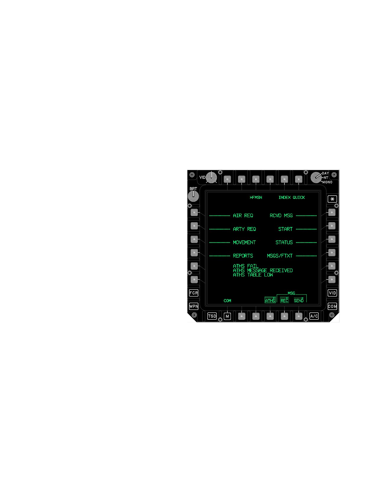
TM 1-1520-251-10
3.53BI.2 Physical Description. The IDM is composed
a. ATHS (INDEX) Page. The ATHS - TACFIRE is ei-
of a single line replaceable unit (LRU) that receives infor-
ther initialized automatically through a DTU load or manu-
mation via the 1553B bus. Information is received from the
ally through the ATHS top level (INDEX) page (fig
DMS, EGI, SP, WP, onboard sensors, Multipurpose Dis-
3-62BU). An automatic initialization is contingent on a
play’s (MPD), Keyboard Unit (KU), and through the receipt
TACFIRE NET having been constructed on the AMPS and
of digital messages. When ATHS is selected, the pro-
downloaded to the DTC. The top level ATHS page is ac-
cessed information may be displayed on either of the
cessed through either the PLT’s or CPG’s top level COM
PLT’s or CPG’s MPD’s. ATHS - TACFIRE messages may
page by selecting the ATHS button. Upon selecting the
be transmitted to and from other ATHS - TACFIRE capable
ATHS button, the ATHS - TACFIRE page last displayed in
aircraft, artillery TACFIRE/FIST systems, handheld data
that crew station will be recalled and displayed. Following
message devices (DMD’s), and SINCGARS configured
an aircraft startup, the initial ATHS button selection will al-
AMPS computers. ATHS-TACFIRE formats complex
ways display the top level ATHS page. The top level
messages such as artillery fire requests, reports, emer-
ATHS page is also referred to as the INDEX page. Re-
gency broadcasts, automatic reporting of status, move-
gardless of what specific ATHS page is currently dis-
ment commands, and general free text messages with au-
played, selecting the INDEX button will command the IN-
tomatic or manual authentication.
DEX page (top level ATHS page) to display.
ATHS - TACFIRE protocol incorporates two modes of op-
eration: AIR (AIRBORNE) NET mode; and TFR (TAC-
FIRE) NET mode. If an ATHS-TACFIRE NET is to be
used exclusively between ATHS - IDM aircraft, then AIR
(default) NET mode should be selected. When commu-
nications must be established with the artillery, legacy
ATHS, or DMD, then the TFR NET mode should be selec-
ted. Differences in message format and capabilities be-
tween the AIR and TFR modes exist.
3.53BI.3 ATHS - TACFIRE Initialization.
NOTE
The AH- 64D’s IDM TACFIRE protocol oper-
ates independently from the IDM AFAPD
protocol. If problems are ever experienced
with one IDM protocol, the other protocol will
usually function normally.
LBA5186
The ATHS - TACFIRE system is a legacy method for es-
Figure 3-62BU. ATHS - TACFIRE INDEX
tablishing TACFIRE NETS, MODEM protocol, BAUD
RATE, etc. Complete functionality for establishing TAC-
FIRE NETS, RETRIES, BAUD RATE, AUTH, BLOCK,
The ATHS top level page reserves the data area beneath
PREAMBLE, MONITOR, and XMIT RADIO now exists in
the last two line keys for ATHS - TACFIRE specific caution/
the COM system (para 3.27).
advisories. ATHS top level page caution/advisories in-
clude:
This section still provides a description of the buttons that
• ATHS MESSAGE RECEIVED
reside on the ATHS page as well as describe in detail the
procedures to transmit specific TACFIRE messages.
• ATHS TABLE LOW
• ATHS TABLE LOW
A complete and detailed description of the ATHS - TAC-
FIRE subsystem is described in Technical Bulletin
ATHS MESSAGE RECEIVED indicates that an ATHS -
11 - 5895 - 1632 - 10. Refer to Appendix A to obtain the
TACFIRE message has been received. ATHS TABLE
complete description of this Technical Bulletin.
LOW indicates the authentication tables have less than 20
Use or disclosure of this information is subject to the restriction(s) on the title page of this document.
3-66.66
Change 3
TM 1-1520-251-10
available lines remaining. ATHS FAIL indicates the IDM’s
NOTE
ATHS - TACFIRE component has failed.
The EUFD will display an ATHS MSG advi-
sory whenever the IDM receives an ATHS -
A total of eight (8) separate sections may be accessed
TACFIRE message.
from the INDEX page. The 8 sections are displayed with
associated line-keys, a series of dashes, aligned with
b. QUICK Button Function. The QUICK button ap-
specific L1 - L4 or R1 - R4 MPD variable action buttons.
pears on every ATHS - TACFIRE page. The QUICK func-
The 8 sections include:
tion provides direct access to any one of the following five
operational ATHS - TACFIRE pages.
• AIR REQ
• Summary Page of Highest Priority Received
• ARTY REQ
Message
• MOVEMENT
• Airborne Mission Summary Page
• Artillery Mission Summary Page
• REPORTS
• Mayday Message Summary Page
• RSVD MSG
• Quick Menu Page
• START
c. START Pages - Description.
• STATUS
• MSGS/FTXT
NOTE
• ATHS - TACFIRE NETS are commonly
In addition to the 8 line key sections three other unique
constructed using the AMPS during pre -
buttons are displayed on the INDEX page:
mission planning. When an AMPS is not
used, ATHS-TACFIRE NETS can be
• QUICK
constructed through the COM NET edit
• SEND
pages.
• HFMSN
• An ATHS-TACFIRE NET established
solely through the AH - 64D’s COM NET
The QUICK button provides direct access to various pre-
edit pages will not support the Auto Ac-
vious/preset messages. The SEND R5 button is displayed
knowledge selection.
on most of the ATHS pages and is only functional when a
• The ZEROIZE line - key button does not
destination subscriber data ID bloc is displayed in L1. The
clear AFAPD messages or communica-
HFMSN button should be selected (boxed) when conduct-
tion NETS.
ing a remote Hellfire mission between AH - 64D aircraft.
The START pages (fig 3-62BV) are also available to
The ATHS - TACFIRE employs a set of ASCII characters
manually initialize the IDM’s ATHS - TACFIRE functional-
to denote operator interface functionality of specific fields.
ity. The pages maintain the files for communication, loca-
An asterisk (*) indicates a current active field. An arrow (>)
tion, GO/NO GO test, time, and authentication. Commu-
that points away from an associated MPD button indicates
nication subscriber identifiers are entered as ORIGIN
that manual KU data entry is allowed. An arrow (<) point-
(ORIG), TEAM (TM), and BROADCAST (BC). Additional-
ing to the MPD button signifies a new page button. An ar-
ly, a ZEROIZE line - key button is provided in the START
row pointing upward (^) besides the associated MPD but-
pages. This ZEROIZE line - key button clears all data and
ton indicates that selecting the button will cycle through
table entries from the IDM’s ATHS - TACFIRE component.
alternative fields. A double pound sign (##) indicates a nu-
The START pages also include six message preset selec-
meric entry button. A double ampersand sign (@@) indi-
tions, six movement preset selections, and a bulk data
cates alpha character entry button.
load send/receive message capability.
Use or disclosure of this information is subject to the restriction(s) on the title page of this document.
Change 3
3-66.67
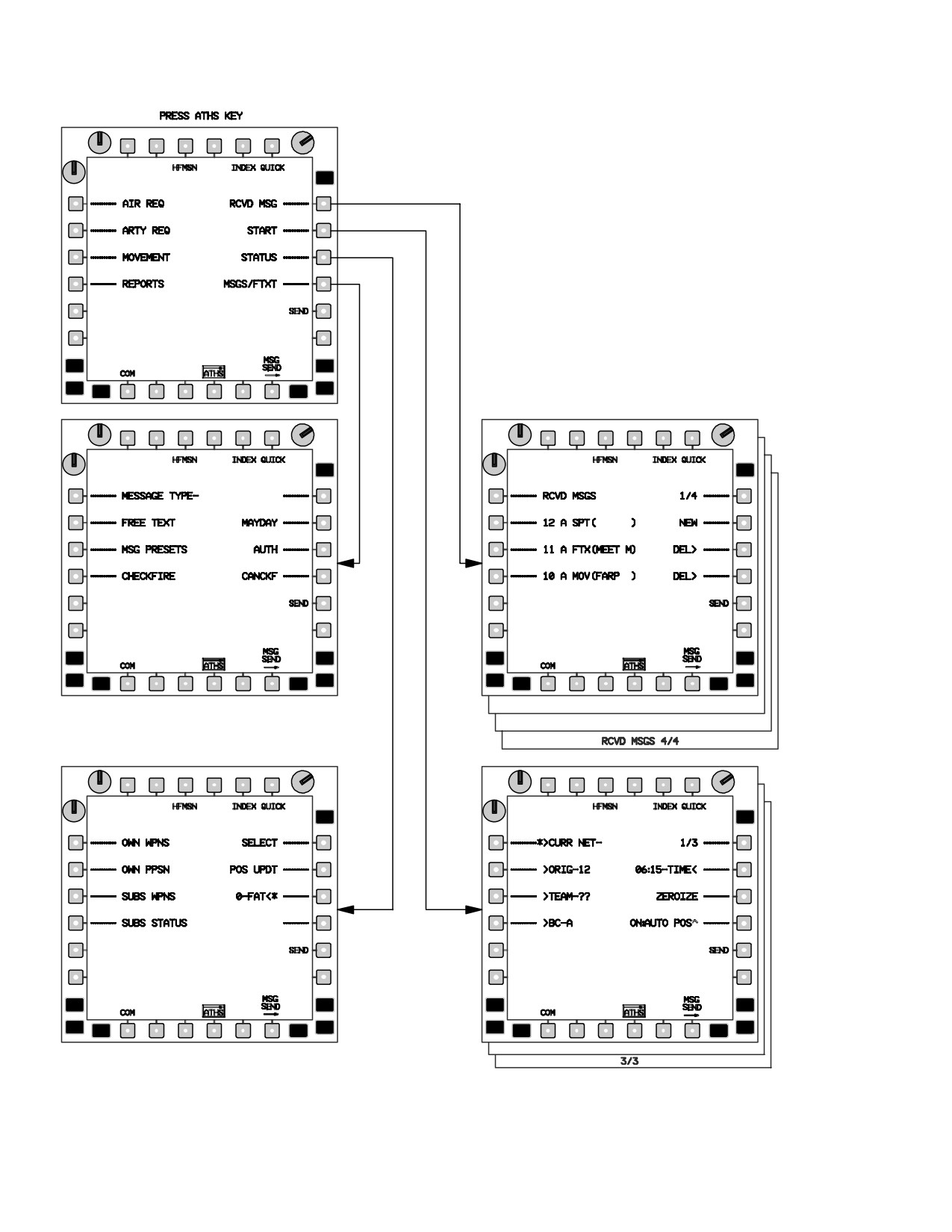
TM 1-1520-251-10
LBA5166
Figure 3-62BV. ATHS TOP LEVEL (INDEX) MENU SELECTIONS
Use or disclosure of this information is subject to the restriction(s) on the title page of this document.
3-66.68
Change 3