FM 3-34.214 (FM 5-250) EXPLOSIVES AND DEMOLITIONS (July 2007) - page 3

Chapter 4
Reconnaissance
4-40. Reconnaissance for continuous bridges is discussed below. The following reconnaissance procedure
is used:
Categorize the bridge.
Measure the bridge using the following measurements, with Figure 4-32 as an example:
Length (L). Measure the span that is planned for attack (in meters) (between the centerlines
of the bearings).
Rise (H). For arch and portal bridges, measure the rise (in meters) (from the springing or
bottom of the support leg to the deck or top of the arch, whichever is greater).
Determine the attack method from Appendix H.
Determine the critical dimensions necessary for charge calculations.
Figure 4-32. Measurements of Continuous Bridges
Bridge Attacks
4-41. As with simply supported spans, two considerations apply when attacking continuous spans: the
point of attack and the line of attack. No common point-of-attack rule exists for all categories of continuous
bridges, but the line-of-attack rule applies to all continuous bridges. That is, the line of attack must be
parallel to the lines of the abutments, and twisting must not occur during the demolition. If the
recommended line of attack involves cutting across transverse beams, the line to cut between adjacent
transverse beams should be repositioned. Table H-5, pages H-9 through H-15, lists attack methods for
continuous spans.
Steel Bridges
4-42. When attacking continuous-span steel bridges, the seesaw or unsupported-member collapse
mechanism should be used. Both mechanisms produce complete cuts through the span. If charges can be
properly placed, these bridges might be demolished with a single-stage attack. However, on particularly
deep superstructures (concrete decks on steel beams), charges designed to sever the deck may not cut
through all of the reinforcing steel. Therefore, during reconnaissance, the possibility of a two-stage attack
on deep, composite superstructures should allows be planned for. Angle cuts should be made at about 70°
to the horizontal to prevent jamming during collapse.
Concrete Bridges
4-43. Continuous concrete bridges are the most difficult to demolish and are poor choices for reserved
demolitions. Even when construction drawings are available and there is ample time for preparation, single-
stage attacks are rarely successful.
4-20
FM 3-34.214
11 July 2007
Bridge Demolition
Arch and Portal Bridges
4-44. For arch bridges and portal bridges with pinned footings, collapse can be guaranteed only by
removing a specified minimum span length. This minimum length is determined by using Table H-3,
page H-3, and the length of the span (denoted as L) and the rise for arch (denoted as H) values determined
by reconnaissance.
MISCELLANEOUS BRIDGES
4-45. There are two types of miscellaneous bridges. They are suspension span bridges and moveable
bridges. The characteristics of these bridges are described in the paragraphs below.
SUSPENSION SPAN BRIDGES
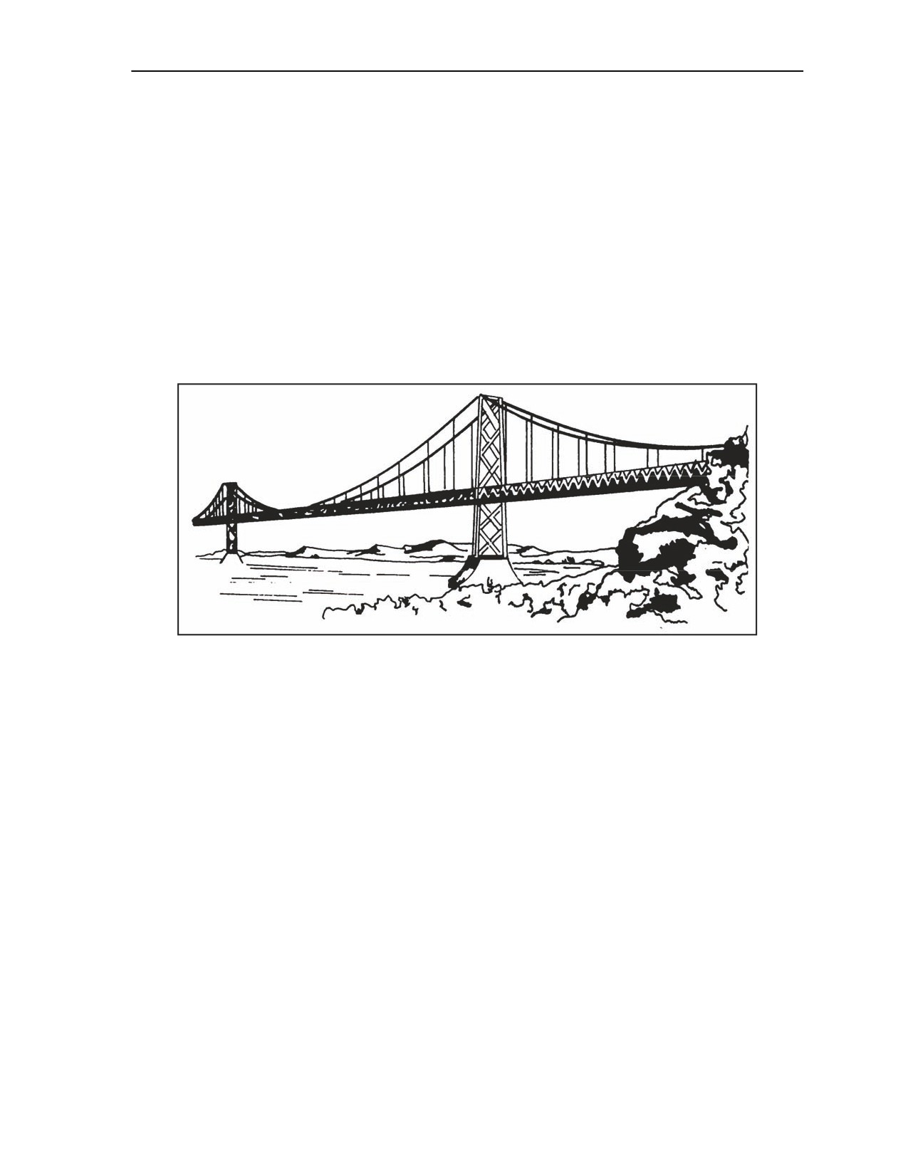
4-46. Suspension-span bridges usually span very large gaps. These bridges have two distinguishing
characteristics: roadways carried by flexible members (usually wire cable) and long spans (Figure 4-33).
Figure 4-33. Suspension Span Bridge
Components
4-47. The components of suspension span bridges are cables, towers, trusses or girders, and anchors.
Suspension bridge cables are usually multiwire-steel members that pass over the tower tops and terminate
at anchors on each bank. The cables are the load-carrying members. (The Golden Gate Bridge has
127,000 miles of wire cable of this type.) The towers support the cables. Towers may be steel, concrete,
masonry, or a combination of these materials. The trusses or girders do not support the load directly; they
only provide stiffening. Anchors hold the ends of the cables in place and may be as large as 10,000 cubic
feet.
Demolishing Methods
4-48. The following paragraphs describe how to destroy major and minor bridges:
Major bridges. Anchors for major suspension bridges are usually too massive to be demolished.
The cables are usually too thick to be cut effectively with explosives. The most economical
demolition method is to drop the approach span or a roadway section by cutting the suspenders
of the main or load-bearing cables. The repair and tactical bridging capabilities of the enemy
determine the length of the target section. When reinforced-concrete towers are present, it may
be feasible to breach the concrete and cut the steel of the towers.
Minor bridges. The two vulnerable points on minor suspension bridges are towers and cables.
The following destruction methods are used:
11 July 2007
FM 3-34.214
4-21
Chapter 4
Towers. Destroy towers by placing tower charges slightly above the level of the roadway.
Cut a section out of each side of each tower. Place the charges so that they force the ends of
the cut sections to move in opposite directions, twisting the tower.
Note. This prevents the end of a single cut from remaining intact. Demolition chambers in some
of the newer bridges make blasting easier, quicker, and more effective.
Cables. Destroy cables by placing charges as close as possible to anchor points, such as the
top of the towers. (Cables are difficult to cut because of the airspace between the individual
wires in the cable.) Ensure that the charge extends no more than one-half the circumference
of the cable.
Note. These charges are usually bulky, exposed, and difficult to place. Shaped charges are very
effective for cutting cable.
MOVABLE BRIDGES
4-49. Movable bridges have one or more spans that open to provide increased clearance for waterway
traffic. The three basic types of movable bridges are swing span, bascule, and vertical lift. The
characteristics of these bridges are described in the paragraphs below.
Swing Span Truss Bridges
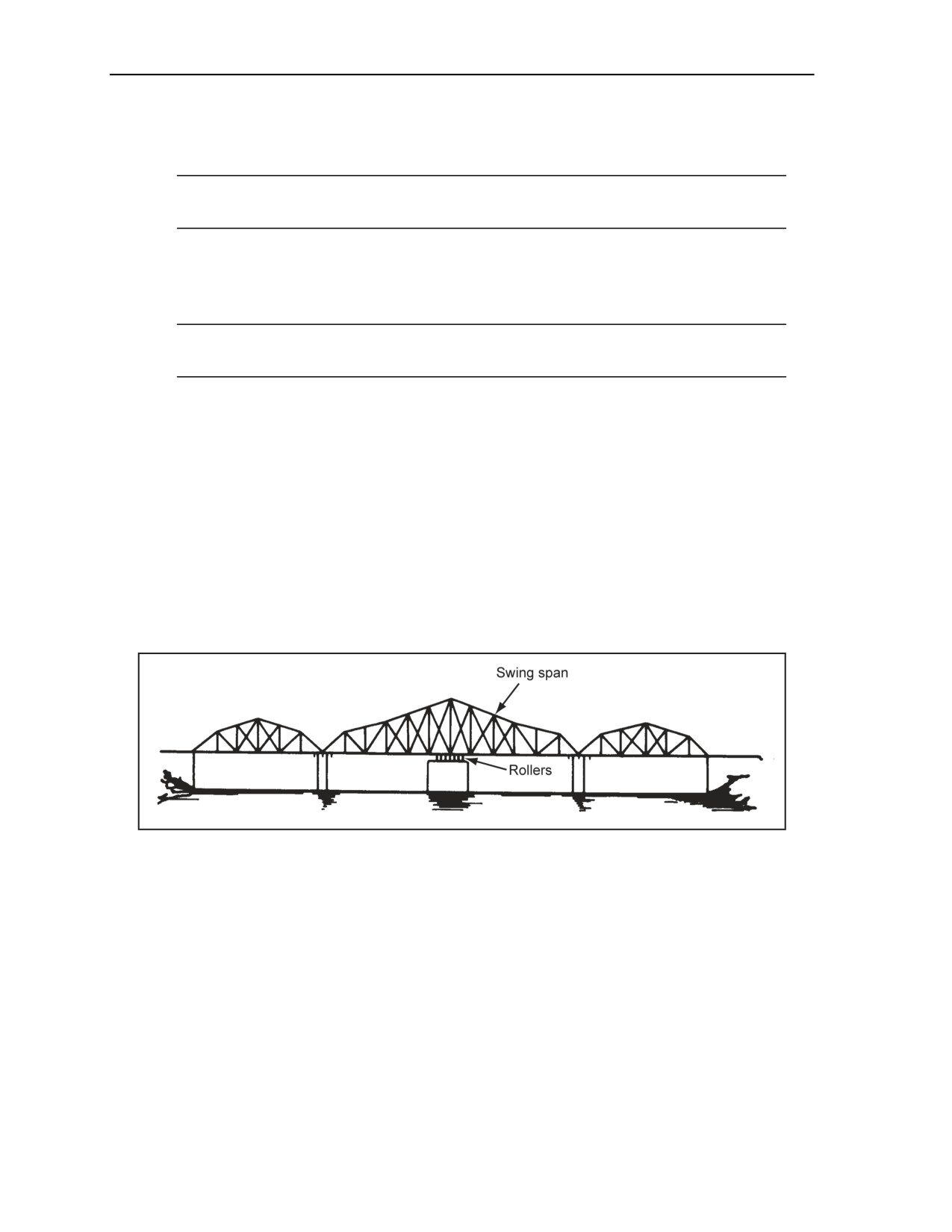
4-50. A swing span bridge is a continuous span capable of rotating on a central pier. The arms of a swing
span truss bridge may not be of equal length. In that case, weights must be added to balance the arms.
Rollers that run on a circular track on top of the central pier carry the weight of the span. The swing span is
independent from any other span in the bridge. A swing span truss bridge is identified by its wide central
pier. This central pier is much wider than the one under a continuous-span bridge that accommodates the
rollers and turning mechanism (Figure 4-34).
Figure 4-34. Swing Span Truss Bridge
4-51. Because swing span truss bridges are continuous bridges, an attack method from the continuous-
bridge section in Appendix H should be used. For partial demolition, open the swing span and damage the
turning mechanism.
Bascule Bridges
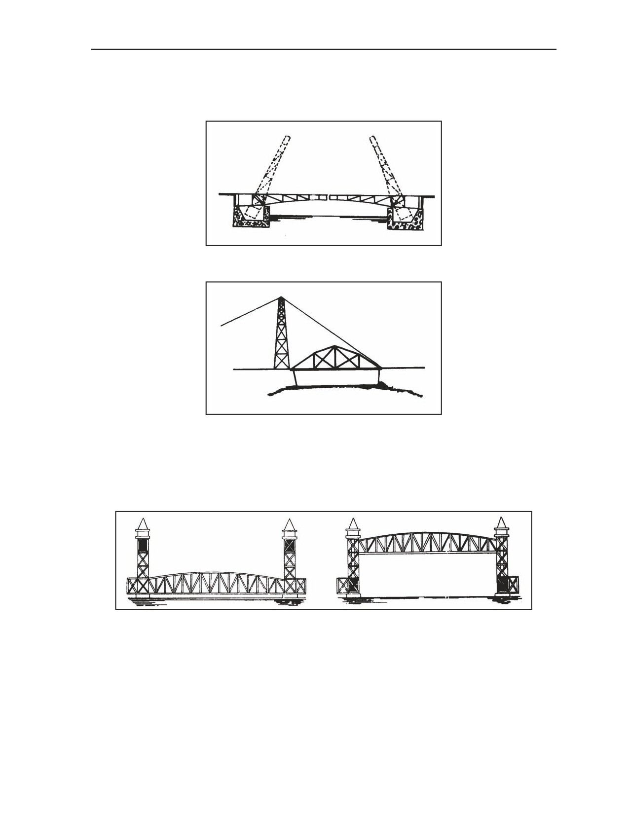
4-52. Bascule bridges are more commonly known as drawbridges. These bridges usually have two leaves
that fold upward (Figure 4-35), but some bascule bridges may have only one leaf (Figure 4-36). The
movable leaves in bascule bridges appear in following three general forms:
Counterweights below the road level (most modern).
Counterweights above the road level (older type).
No counterweights (the oldest type, usually timber, lifted by cable or rope).
4-22
FM 3-34.214
11 July 2007
Bridge Demolition
4-53. To destroy this bridge, demolish the cantilever arms with an attack method appropriate for simply
supported bridges. For partial demolition, the bridge and jam should be opened or the lifting mechanism
destroyed.
Figure 4-35. Double-Leaf Bascule Bridge
Figure 4-36. Single-Leaf Bascule Bridge
Vertical Lift Bridges
4-54. These bridges have simply supported, movable spans that can be raised vertically in a horizontal
position. The span is supported on cables that pass over rollers and connect to large, movable
counterweights (Figure 4-37).
Figure 4-37. Vertical Lift Bridge
4-55. To destroy this bridge, the movable span should be demolished with an attack method appropriate for
simply supported bridges. Another method is to raise the bridge, and cut the lift cables on one end of the
movable span. The movable span will either wedge between the supporting towers or fall free and severely
damage the other tower.
Floating Bridges
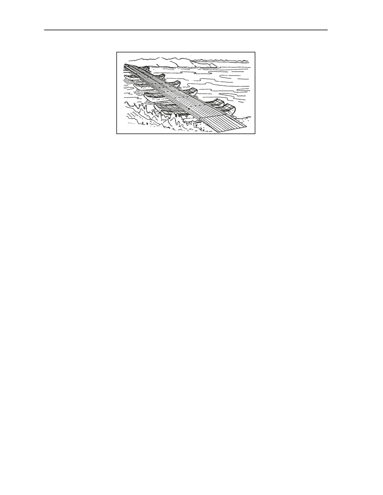
4-56. Floating bridges consist of a continuous metal or wood roadway. These bridges are supported by
floats or pontoons (Figure 4-38, page 4-24).
11 July 2007
FM 3-34.214
4-23
Chapter 4
Figure 4-38. Floating Bridge
Pneumatic Floats
4-57. Pneumatic floats are airtight compartments of rubberized fabric inflated with air. For a hasty attack
of these bridges, the anchor cables and the bridle lines are cut with axes and the steel cables with
explosives. Also, the floats are punctured with small arms or machine-gun fire. Using weapons to destroy
the floats requires a considerable volume of fire because each float has a large number of watertight
compartments. Another method is to make a clean cut through the float, using detonating cord stretched
snugly across the surface of the pontoon compartments. One strand of cord is enough to cut most fabrics,
but two strands may be necessary for heavier materials. Also, one turn of a branchline cord is placed
around each inflation valve. This prevents the raft from being reinflated if it is repaired. Do not use
mainline cords to cut valves because the blast wave may fail to continue past any sharp turn in the cord.
Rigid Pontoons
4-58. Rigid pontoons are made of wood, plastic, or metal. To destroy these bridges, a 1/2-pound charge is
placed on the upstream end of each pontoon at water level. A charges are detonated simultaneously. If the
current is rapid, the anchor cables are cut so that the bridge will be carried downstream. Another method is
to cut the bridge into rafts. One-half pound charges are placed at each end of each pontoon, and detonate
them simultaneously. To destroy metal tread ways on floating bridges, the steel-cutting formula is used (see
Chapter 3). The placement and size of the charges depend on the bridge type. Placing cutting charges at
every other joint in the tread way will damage the bridge beyond use.
Bailey Bridges
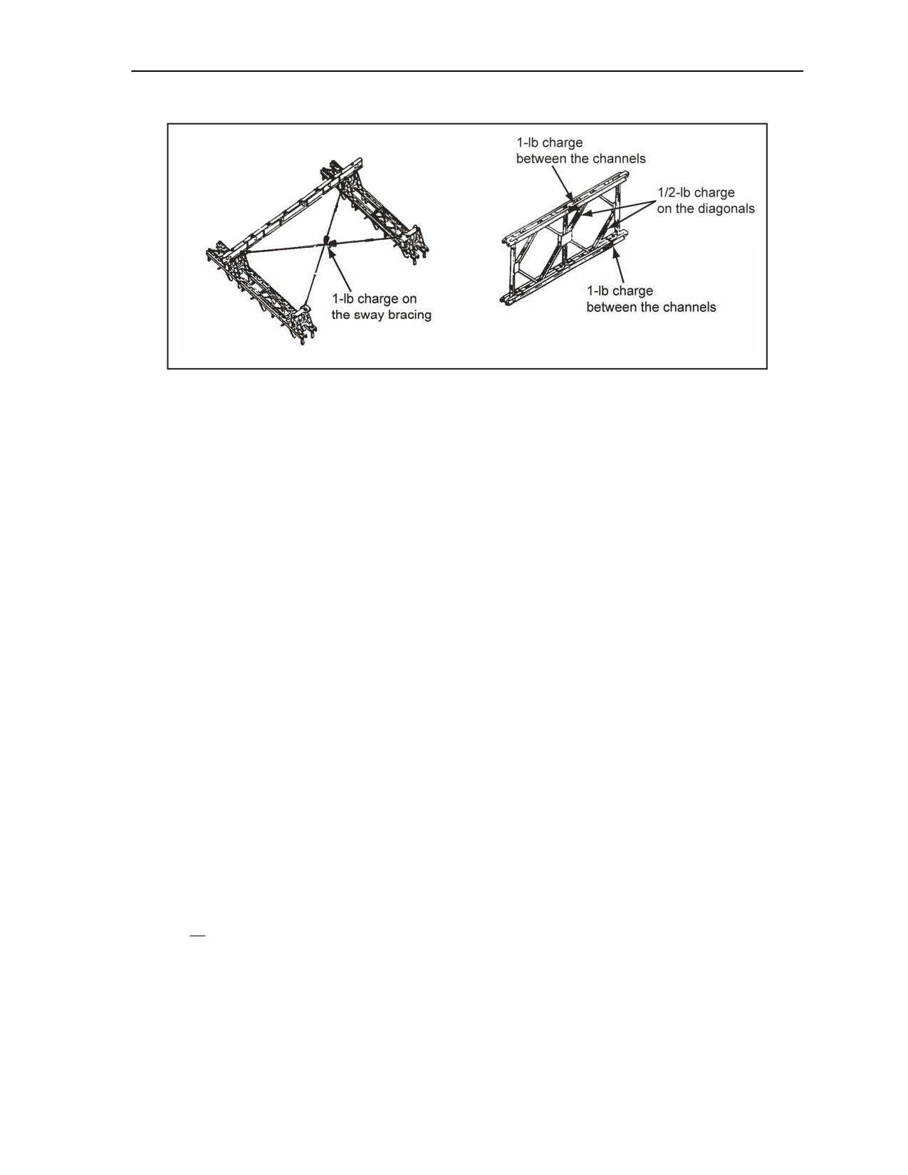
4-59. To destroy Bailey bridges, 1-pound charges are placed between the channels of the upper and lower
chords. One-half pound charges for cutting diagonals and 1-pound charges are used for cutting sway
bracing (Figure 4-39).
4-24
FM 3-34.214
11 July 2007
Bridge Demolition
Figure 4-39. Bailey Bridge Demolition
In-Place Demolitions
4-60. The bridge should be cut in several sections by attacking the panels on each side, including the sway
bracing. The attack angle should be 10° to the horizontal to prevent jamming. In double-story or triple-story
bridges, increase the charges on the chords at the story-junction line. For further destruction, charges are
placed on the transoms and stringers.
In-Storage or In-Stockpile Demolition
4-61. When abandoning bridges in storage, no component is left that the enemy can use as a unit or for
improvised construction. The essential components should be destroyed so that the enemy cannot easily
replace or manufacture them. Panel sections are considered essential components. To render the panels
useless, the female lug in the lower tension chord removed or distorted. All panels should be destroyed
before destroying other components.
ABUTMENTS
4-62. To demolish abutments, charges are placed in the fill behind the abutment. This method uses less
explosive than external breaching charges and also conceals the charges from the enemy. The disadvantage
is the difficulty in placing the charges. When speed is required, do not place charges behind abutments if it
is known that the fill contains large rocks.
ABUTMENTS 5 FEET THICK OR LESS
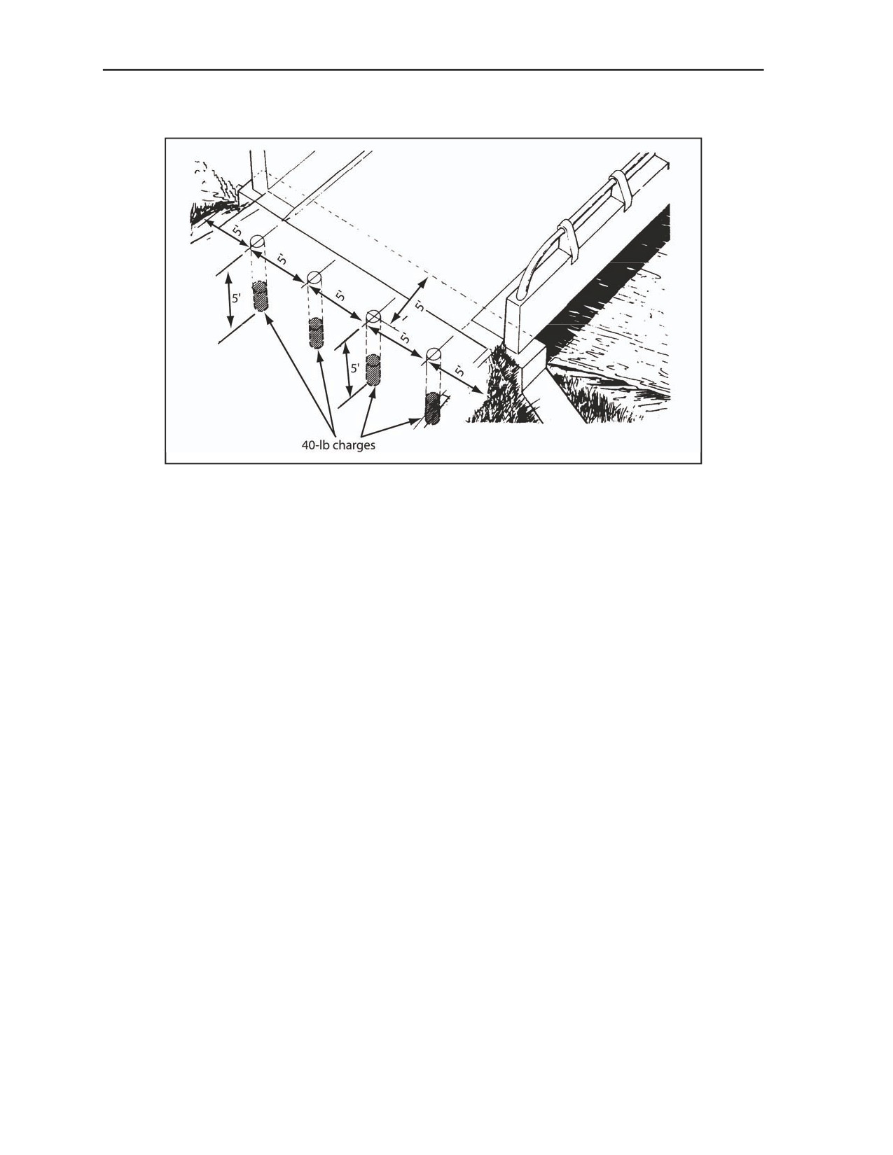
4-63. Abutments 5 feet thick or less are demolished by placing a line of 40-pound cratering charges on
5-foot centers, in boreholes 5 feet deep, and located 5 feet behind the face of the abutment (using the triple-
nickel-forty method). The first hole is placed 5 feet from either end of the abutment, then this spacing
continues until a distance of 5 feet or less remains between the last borehole and the other end of the
abutment (Figure 4-40, page 4-26). If the bridge approach is steep, the breaching charges are placed against
the rear of the abutment. The number of 40-pound cratering charges is determined as follows:
W
N =
+ 17 (-1)
5
where—
N
= number of charges; round UP to next higher whole number
W
= abutment width (in feet)
5
= center mass distance between boreholes
17 = constant to find the number of charges
11 July 2007
FM 3-34.214
4-25
Chapter 4
1
= convert spaces to holes
Figure 4-40. Abutment Destruction (5 Feet Thick or Less)
ABUTMENTS OVER 5 FEET THICK
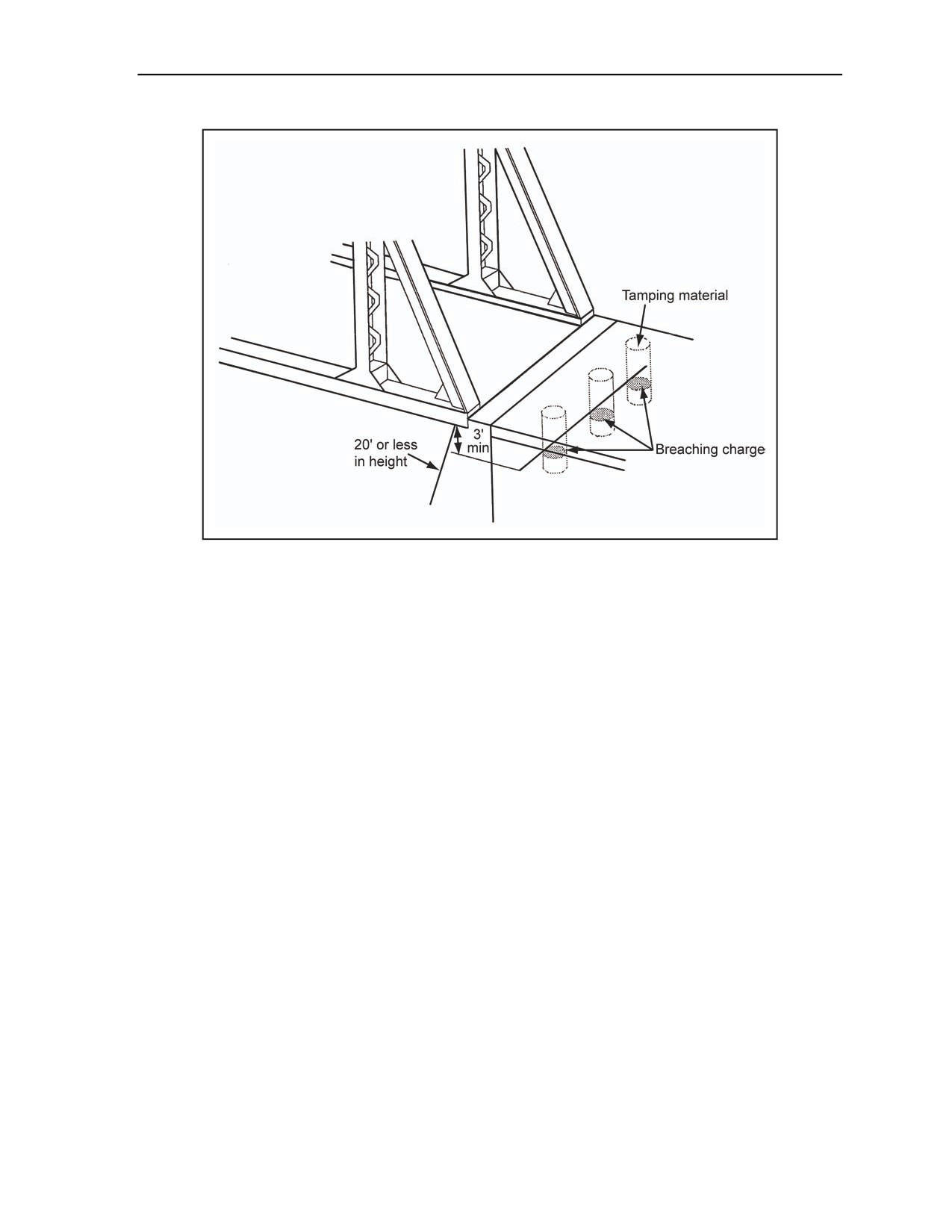
4-64. These abutments are destroyed with breaching charges in contact with the back of the abutment. The
amount of each charge is calculated using the breaching formula in the equation in paragraph 3-39. The
abutment thickness is used as the breaching radius. The number of charges and their spacing is determined
using the equation in paragraph 3-46. Charges are placed at least 3 feet below the bridge seat (where the
bridge superstructure sits on the abutment) (Figure 4-41).
4-26
FM 3-34.214
11 July 2007
Bridge Demolition
Figure 4-41. Abutment Destruction (Over 5 Feet Thick)
ABUTMENTS OVER 20 FEET HIGH
4-65. These abutments are demolished by placing a row of breaching charges at the base of the abutment,
on the gap side, in addition to the charges specified the following on intermediate supports. All charges are
fired simultaneously. This method tends to overturn and completely destroy the abutment.
WING WALLS
4-66. If the wing walls can support a rebuilt or temporary bridge, destroy the wing walls by placing
charges behind them the same as for abutments. See Figure 4-40 and Figure 4-41.
INTERMEDIATE SUPPORTS
4-67. Intermediate supports include external and internal charges. Each of these are discussed in the
paragraphs below.
EXTERNAL CHARGES
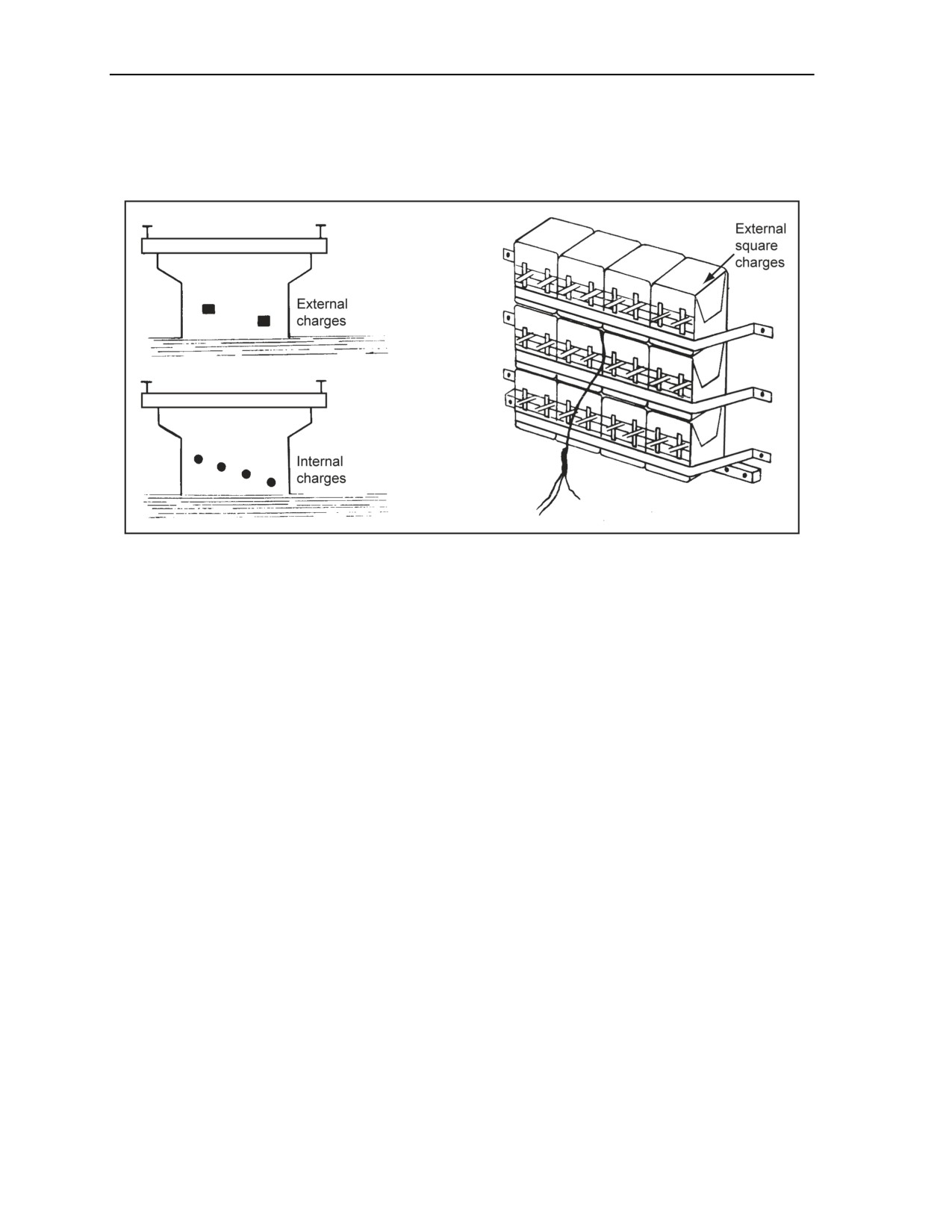
4-68. External charges are placed at the base of the pier or higher and are spaced by more than twice the
breaching radius (Figure 4-42, page 4-28). Charges are staggered to leave a jagged surface to hinder future
use. All external charges are thoroughly tamped with earth and sandbags if time, size, shape, and location
of the target permits.
INTERNAL CHARGES
4-69. Internal charges on intermediate supports require less explosive than external charges. (For charge
placement, see Figure 4-42.) However, unless the support has built-in demolition chambers, this method
requires an excessive amount of equipment and preparation time. The equation in paragraph 3-39 should be
used to determine the amount of each charge. M112 (composition C4) is ideal for internal charges. All
charges of this type should be thoroughly tamped with nonsparking tools (such as blunt, wooden tamping
11 July 2007
FM 3-34.214
4-27
Chapter 4
sticks or similar tools). If the support has demolition chambers, the charges are placed in boreholes created
with shaped charges or drilled with pneumatic or hand tools. A 2-inch-diameter borehole holds about 2
pounds of explosive per foot of depth. The steel reinforcing bars, however, make drilling in heavily
reinforced concrete impractical.
Figure 4-42. Intermediate-Support Placement Charges
4-28
FM 3-34.214
11 July 2007

This chapter implements Standardization Agreement (STANAG) 2017,
STANAG
2077, STANAG
2123, Quadripartite Standardization
Agreement (QSTAG) 508, and QSTAG 743.
Chapter 5
Demolition Operations and Training
Planning for demolitions and preliminary and reserved demolitions are described in
this chapter, including Orders for Demolition which is outlined in STANAG 2077.
The chapter also provides information on how to prepare DA Form 2203 (Demolition
Reconnaissance Record) and how to complete an obstacle folder as outlined in
STANAG 2123. This chapter also provides details for each simulated demolition
type, the priming methods for each type, the initiating set preparation, and the setup
of firing systems.
SECTION I - DEMOLITION OPERATIONS
5-1. This section provides information about the use of obstacles, the types of operations, demolition
planning, demolition orders, preliminary and reserved demolitions, reconnaissance orders and records, and
obstacle folders.
DEMOLITION OBSTACLES
5-2. A demolition obstacle is an obstacle created by using explosives. Although engineers use
explosives for quarrying, land-clearing, and other projects, their most important use is creating demolition
obstacles. Engineers use demolition obstacles in conjunction with many other types of obstacles, including
mines. They also use explosives to destroy materiel and facilities that must be abandoned
(denial
operations).
BARRIERS AND DENIAL OPERATIONS
5-3. Division or higher-echelon commanders direct the use of extensive barriers and denial operations.
Commanders must carefully prepare and closely coordinate these operations with all tactical plans.
Engineer units provide technical advice and supervision, estimate the resources necessary for obstacle
construction, construct barriers or obstacles, and recommend allocation of engineer resources. They usually
construct demolition obstacles because they have the special skills and equipment to accomplish these
tasks.
DEMOLITION PLANNING
5-4. A demolition plan is the documentation with data required for the preparation of a single
demolition. Any demolition project is based on careful planning and reconnaissance. The following factors
are used as a basis for selecting and planning demolition projects:
The mission.
The limitations and instructions from a higher authority.
The current tactical and strategic situation and future plans (conditions that indicate the length of
time the enemy must be delayed, the time available for demolition, and the extent of denial
objectives).
11 July 2007
FM 3-34.214
5-1

Chapter 5
The capabilities and limitations of the enemy, as well as the effect that denial operations have on
enemy forces, strategically and tactically.
The likelihood that friendly forces may reoccupy the area, requiring obstacle neutralization.
The economy of effort.
The time, material, labor, and equipment available.
The effect on the local population.
The target protection required.
DEMOLITION ORDERS
5-5. Authorized commanders use orders for the demolition to pass their orders to the demolition guard (a
local force positioned to ensure that a target is not captured by an enemy before orders are given for its
demolition and before the demolition has been successfully fired [the definition was shortened, and the
complete definition is printed in the glossary]) (FM 1-02) (JP 1-02) and the demolition firing party (the
party at the site that is technically responsible for the demolition and that actually initiates detonation or
fires the demolitions) (FM 1-02) (JP 1-02). The orders for the demolition, as outlined in STANAG 2017
and QSTAG 508, is a standard four-page form used by the North Atlantic Treaty Organization (NATO) and
ABCA countries. This form is used for preparing all reserved and preliminary demolitions. Page one of the
form contains the instructions, duties, and responsibilities of demolition personnel.
PRELIMINARY DEMOLITIONS
5-6. With prior authority, a preliminary demolition is detonated immediately after preparation.
Preliminary demolitions present fewer difficulties to both commanders and engineers than do reserved
demolitions. Commanders may restrict preliminary demolitions for tactical, political, or geographical
reasons.
ADVANTAGES
5-7. Preliminary demolitions have some advantages. They are as follows:
Engineers normally complete each task and move to the next without having to leave demolition
guards or firing parties at the site.
Preparation efforts are less subject to interference by enemy or friendly troops.
Elaborate precautions against failure are not required; preliminary demolitions require only
single-firing systems.
Engineers can perform demolition operations for a particular target in stages rather than all at
once.
PROGRESSIVE PREPARATION
5-8. When preparation time is limited, engineers prepare the demolition in progressive stages. This gives
the engineers the ability to create effective obstacles even if preparations must stop at any stage.
RESERVED DEMOLITIONS
5-9. The responsible commander must carefully control a reserved demolition target. The target may be a
vital part of the tactical or strategic plan or the demolition will be performed in close contact with the
enemy.
5-2
FM 3-34.214
11 July 2007

Demolition Operations and Training
CONSIDERATIONS
5-10. Occasionally, errors in orders, control, or timing cause serious consequences during demolition
operations. In addition, engineers may encounter the following special problems when dealing with
reserved demolition targets:
Traffic lanes must be kept open until the last moment. This means they cannot use the simplest
and quickest demolition techniques to accomplish the mission.
Demolitions must be weatherproofed and protected from traffic vibrations and enemy fire over
long periods. Dual-firing systems must be used and demolitions must be carefully placed and
protected from passing vehicles or pedestrians.
Demolition sites must be guarded until the demolitions are fired.
STATE OF READINESS—STATE 1 (SAFE)
5-11. In state 1, the demolition charges are in place and secure. Vertical and horizontal ring mains are
installed (Figure 2-28, page 2-26) and not connected. Charges are primed with detonating cord knots,
M151, M152, or wraps to minimize the time necessary to convert the system from state of readiness—state
1 (SAFE) to state of readiness—state 2 (ARMED). Charges that require blasting caps for priming cannot be
primed at state of readiness—state 1, and branchlines with caps crimped to them cannot be connected to
ring mains. Blasting caps and initiating sets are not attached to charges or firing systems. M151 and M152
boosters are the preferred priming method.
STATE OF READINESS—STATE 2 (ARMED)
5-12. In state 2, blasting caps are in appropriate charges, and initiating sets are connected to ring mains. All
charges and firing systems are complete and ready for detonation. The demolition is ready for immediate
firing.
RESPONSIBILITIES
5-13. The paragraphs below describe the responsibilities of authorized commanders, demolition guard
commanders, and demolition-firing party commanders.
Authorized Commanders
5-14. These commanders have overall responsibility for the operational plan. At any stage of the operation,
they may delegate responsibilities. For example, when authorized commanders withdraw through other
units’ intermediate positions, they pass control to the commanders holding the intermediate positions. The
commanders holding the intermediate positions then become the authorized commanders. Authorized
commanders—
Designate demolition targets as reserved targets.
Order the demolition guard, and detail the strength and composition of the guard party.
Specify the state of readiness and order changes to the state of readiness, if necessary.
Give the orders to fire demolitions.
Give the demolition guard commander or the demolition-firing party commander the authority,
in case of imminent capture, to fire the demolition on his own initiative.
Destroy captured or abandoned explosives and demolition materials to prevent them from falling
into enemy hands.
Note. Commanders should carefully select the demolition site and consider all safety precautions
necessary when destroying abandoned demolitions. Chapter 6, Section IV, covers the procedures
and methods for destroying explosives.
Issue written instructions (demolition orders) to the unit providing the demolition guard and
demolition-firing party.
11 July 2007
FM 3-34.214
5-3

Chapter 5
Notify all headquarters of any delegation of authority or reclassification of any demolition from
a reserved to a preliminary status.
Establish effective channels for communicating firing orders and readiness states to demolition
guard commanders or demolition-firing party commanders.
Demolition Guard Commanders
5-15. These commanders are normally the infantry or armor task force commanders who control the target
area. The demolition guard commanders—
Command all troops and firing parties at reserved demolitions.
Provide protection for reserved demolitions, firing parties, and targets.
Control all traffic over or through targets.
Pass written state-of-readiness orders to demolition-firing party commanders, including changes
to these orders.
Keep authorized commanders informed of the status of preparations, targets, and operational
situations at sites.
Pass written firing orders to demolition-firing party commanders to fire demolitions.
Report demolition results to authorized commanders.
Maintain succession
(chain of command) lists for appointment to demolition guard and
demolition-firing party commanders.
Demolition-Firing Party Commanders
5-16. These commanders are normally officers or noncommissioned officers (NCOs) from the engineer
unit that prepared the demolitions. They supervise the preparing, charging, and firing of the demolition.
Demolition-firing party commanders—
Maintain the state of readiness that is specified by authorized commanders and advise
demolition guard commanders of the time requirements for changing states of readiness and
completing obstacles.
Fire demolitions when ordered by the authorized commander and ensure that demolitions are
successful and complete.
Report the results of demolitions to demolition guard commanders or, if none, to the authorized
commanders.
Report the results of demolitions up the chain of command and complete of the obstacle folder,
if required.
Maintain succession
(chain of command) lists for appointment as demolition-firing party
commander, if the initial commander should become injured.
COMMAND AND CONTROL OF RESERVED DEMOLITIONS
5-17. The paragraphs below discuss the command and control of reserved demolitions. Discussed is the
command post, the firing point, alternate positions, the checkpoint, and refugee-control points.
Command Post
5-18. The demolition guard commander should place his command post where he can best control the
defense of the demolition target from the friendly side. However, this location may conflict with the
requirements of the demolition firing point, which should be close to or collocated with the command post.
Usually, some compromise is necessary.
Firing Point
5-19. The firing point should be as close to the target as safety allows. The firing point must protect the
firing party from the effects of blast and falling debris and be positioned so that the demolition-firing party
commander is—
5-4
FM 3-34.214
11 July 2007

Demolition Operations and Training
Easily accessible to the demolition guard commander for receiving orders.
In close contact with the firing party.
Able to see the entire target.
Alternate Positions
5-20. The demolition guard commander should designate an alternate command post and firing point, if
possible. The firing party should be able to fire the demolitions from either the primary or alternate firing
points.
Checkpoint
5-21. When units are withdrawing from an enemy advance, identification can be a problem. Withdrawing
troops are responsible for identifying themselves to the demolition guard. The demolition guard must
always establish and operate a checkpoint. The demolition guard commander may use military police to
perform this duty. Good communication is essential between the checkpoint and the demolition guard
commander. Each unit withdrawing through the demolition target should send a liaison officer to the
checkpoint, well in advance of the arrival of the withdrawing unit.
Refugee-Control Points
5-22. The demolition guard commander may need to establish and operate a refugee-control point for
civilian traffic. He should place a checkpoint on the enemy bank and a release point on the friendly bank to
control refugees. The commander may use military or local police to operate the control points. Personnel
operating the checkpoints should halt refugees off the route and then escort them, in groups, across the
target to the release point. Refugees must not interfere with the movement of withdrawing forces or
demolition preparations.
RECONNAISSANCE ORDERS
5-23. Thorough reconnaissance is necessary before planning a demolition operation. Reconnaissance
provides detailed information in all areas related to the project. Before conducting any reconnaissance, the
reconnaissance party commander must receive clear objectives. The reconnaissance order specifies these
objectives. This information helps the reconnaissance party to determine the best method of destroying the
target and to estimate the preparation time required. For example, if the reconnaissance party knows that
manpower and time are limited but explosives are plentiful, they may design demolitions requiring few
men and little time but large quantities of explosives. These orders should detail the reconnaissance party to
determine the following:
The location and nature of the target.
The purpose of the demolition operation (to delay an enemy infantry battalion for 3 hours).
The proposed classification of the demolition (reserved or preliminary).
The firing system type desired (dual or single).
The economy of effort (whether the demolition must be completed in one stage or multiple
stages).
The utility of the target during demolition operations (whether the target must remain open to
traffic during demolition preparations).
The amount of time allowed or expected between preparation and execution of the demolition
operation.
The amount of time allowed for changing the state of readiness (safe to armed).
The labor and equipment available for preparing the demolitions.
The types and quantities of explosives available.
11 July 2007
FM 3-34.214
5-5

Chapter 5
RECONNAISSANCE RECORD
5-24. A reconnaissance party reports the results of its reconnaissance on DA Form 2203. The form is used
with the appropriate sketches to record and report the reconnaissance of military demolition projects.
Figure I-1, page I-4, contains a sample of DA Form 2203 and instructions to complete it. Available paper is
used and attached to the completed DA Form 2203.
5-25. When time and conditions permit, the reconnaissance report is used as the source document for
preparing the obstacle folder. If the obstacle folder is not available, this report is used in its place. In certain
instances, the report may require a security classification. For the required information and instructions, see
DA Form 2203.
OBSTACLE FOLDER
5-26. The obstacle folder, as outlined in STANAG 2123 and QSTAG 743, provides all the information
necessary to complete a specific demolition operation. NATO and ABCA personnel use this booklet to
collect information and to conduct demolition operations. The responsible commander should prepare an
obstacle folder during peacetime for all preplanned targets to allow for efficient demolition operations.
Obstacle folders are prepared for reserved and preliminary demolitions. The obstacle folder is not used in
tactical situations because the detailed information in the obstacle folder, including multiple languages, is
not easily completed under field or tactical conditions.
LANGUAGE
5-27. Since not all NATO and ABCA personnel speak the same language, obstacle folders must be
multilingual. The preparing unit may speak a different language than the unit actually conducting the
demolition operation. Therefore, it is essential to prepare the obstacle folder in more than one language.
However, prepare map notes, plans, sketches, and so forth in one language, and provide translations for the
other languages in the available space. The languages necessary in an obstacle folder is determined based
on the following:
The languages of the units involved in the demolitions.
The language of the host nation.
One of the two official NATO languages (English or French).
CONTENTS
5-28. The obstacle folder contains six sections for recording information. Additional information may be
noted in the appropriate place within the obstacle folder and then inserted as an additional page
immediately following the notation (for example, “location and type, see page 4a”). The following are the
six parts of the obstacle folder:
Location of the target.
Supply of explosives and equipment.
Orders for preparing and firing.
Handover and takeover instructions.
Demolition report.
Official signature.
SPECIAL INSTRUCTIONS
5-29. The list of explosives, stores, and mines required does not cover every possible situation. However, it
does indicate a logical order for recording or determining the required materials. Only the materials
required for the particular target are marked. The transport team leader uses the first list. For major
operations, note the size, composition, and mission of the various participating work parties. The
demolition-firing party commander may detach the first copy of the demolition report and forward it to a
higher-echelon headquarters.
5-6
FM 3-34.214
11 July 2007

Demolition Operations and Training
SECTION II - DEMOLITION EFFECTS SIMULATOR DEVICES
5-30. To meet the field requirement, all demolition effects simulator (DES) training devices must be the
same weight, size, and shape as the real item to produce realistic loads on both the individual Soldier and
the logistics system, and they should produce enough visual and sound effects to enhance battlefield
realism. All safety precautions should be followed for live explosives and demolitions when using DESs.
All Soldiers will observe the standard operational and safety procedures in this manual when using DESs.
All MSDs should be observed, even though, realistically, these safety distances are less for DESs.
OVERVIEW
5-31. Currently, 10 DESs are available for field training exercises. These devices simulate the—
Sheet explosive.
M112 (composition C4) block.
1-pound TNT block.
M5A1 demolition block.
M183 demolition (satchel) charge.
M2A3 15-pound shaped charge.
M3 40-pound shaped charge.
40-pound cratering charge.
Bangalore torpedo.
M1 military dynamite.
5-32. DES devices can simulate blowing mines in place, destroying timber trestle bridges, destroying
captured equipment and supplies, cratering, and gaining access to a building during training for urban
operations. All of these missions can be executed safely with little or no damage to facility infrastructures.
5-33. All charges except the M112 (composition C4) block and the sheet explosive are chalk charges.
Chalk charges are various containers filled with a chalk powder, sand mixture, and detonating cord. The
detonating cord is the explosive propellant that discharges the chalk powder. The M112 DES block is a
nonexplosive clay compound that replicates composition C4. The sheet explosive is made of nonexplosive
rubber matting. The explosive signatures come strictly from the detonating cord blast.
PREREQUISITES
5-34. Soldiers who assemble DES devices must be familiar with all detonating cord priming methods (see
Chapter 2). The 8-wrap Uli knot is the primary priming method. It gives the DES the explosive power to
create the desired sound signatures and expel the chalk that creates the visual signature. Other priming
methods are the girth hitch with an extra turn, the triple-roll knot, the double-overhand knot, and the
common and alternate methods.
SECTION III - CHARACTERISTICS AND ASSEMBLY INSTRUCTIONS
5-35. This section gives guidance in the assembly and use of DES devices. The materials, assembly
instructions, and uses are only recommendations pertinent to each product. However, as a standard marking
system, all DESs and DES containers are labeled with red lettering. (See Appendix J for a list of DES
materials.)
SHEET EXPLOSIVE DEMOLITION EFFECTS SIMULATOR
5-36. The sheet explosive demolition charge DES is eight pieces of rubber matting cut into sheets identical
to plastic-sheet explosive. The sheets are glued together (making four 1/4-inch sheets) and then packed into
clear plastic bags, marked with DES labels.
11 July 2007
FM 3-34.214
5-7
Chapter 5
PRIMARY USES
5-37. This charge is primarily used for the following charges:
Ribbon.
Saddle.
Diamond.
Steel-cutting.
ASSEMBLY INSTRUCTIONS
5-38. The following steps should be used to assemble sheet explosive DESs:
Step 1. Cut out eight pieces of rubber matting (1/8 by 3 by 11 inches).
Step 2. Place two pieces of matting side by side.
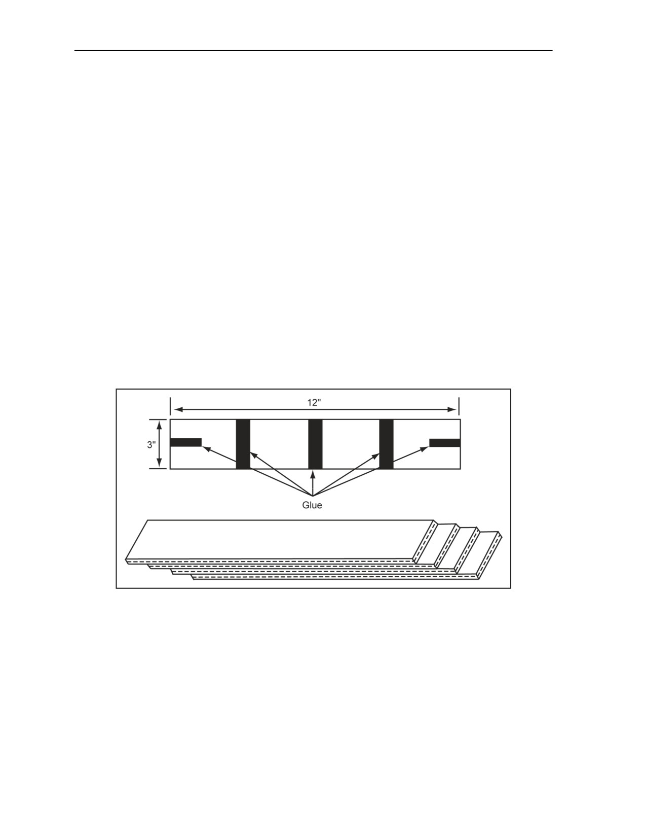
Step 3. Put glue on the rough side of one sheet (Figure 5-1), leaving enough space for inserting
the MDI cap. Do not put glue where the MDI cap will be inserted for priming.
Step 4. Place the rough sides of the sheets together (Figure 5-1), and weight with a heavy object
until the glue dries.
Step
5. Ensure that the glue is completely dry, and package four
1/4-inch-thick sheets
(Figure 5-1) into a plastic bag.
Step 6. Seal the plastic bag with clear tape.
Step 7. Place a DES label on the package.
Step 8. Place 20 DES charges into each shipping container.
Step 9. Label each container.
Figure 5-1. Sheet Explosive DES Assembly
SPECIFICATIONS
5-39. The sheet explosive DES specifications are as follows:
Weight: 2 pounds.
Dimensions: 12 by 3 by 1/4 inches.
Packaging: 20 per container.
Container: 13 3/8 by 15 1/2 by 7 5/8 inches.
BILL OF MATERIALS
5-40. The bill of materials (BOM) for a sheet explosive is shown in Table 5-1.
5-8
FM 3-34.214
11 July 2007

Demolition Operations and Training
Table 5-1. BOM for a Sheet Explosive DES
Material
Quantity
Rubber matting, 18 inch
8 ea
Glue
6 oz
Clear plastic bag
1 ea
Clear tape
2 ft
Two-sided adhesive tape
2 ft
DES label
1 ea
M112 (COMPOSITION C4) BLOCK DEMOLITION EFFECTS
SIMULATOR
5-41. The M112 (composition C4) block DES is made from 1 1/4 pounds of moist pottery clay
(nonexplosive), formed and packaged like composition C4. It is then packed in clear plastic wrap with DES
markings and pressure-sensitive adhesive tape on the back. The tape is protected by a peel-away paper
cover.
PRIMARY USES
5-42. The M112 charge is used primarily for steel-cutting charges, forced entry of buildings, breaching,
cutting timber, demolishing bridges, and neutralizing mines.
ASSEMBLY INSTRUCTIONS
5-43. The following steps should be used to assemble M112 (composition C4) block DESs:
Step 1. Remove the moist pottery clay from the shipping container.
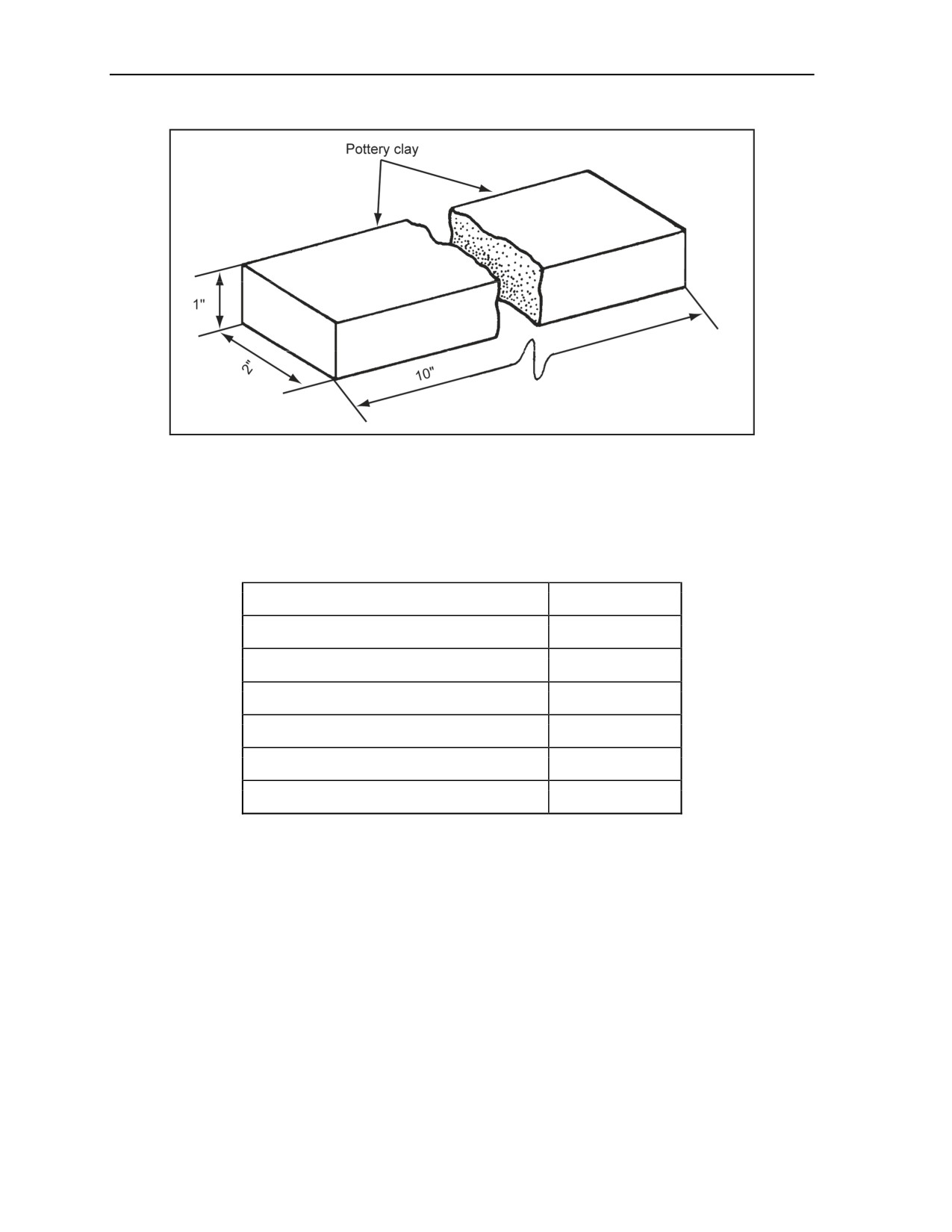
Step 2. Mold the clay into a 1 1/4-pound block. Use a mold to form the clay correctly (1 by 2 by
10 inches) (Figure 5-2, page 5-10).
Step 3. Cover the block with a thin covering of mineral oil.
Step 4. Place the block into a clear plastic bag, and seal the bag tightly with clear tape.
Step 5. Place two-sided adhesive tape on the backside of the packaged clay block.
Step 6. Label the front with a DES label.
Step 7. Box 30 DES blocks per shipping container.
Step 8. Label each container.
SPECIFICATIONS
5-44. The M112 block DES specifications are as follows:
Weight: 1 1/4 pounds.
Dimensions: 1 by 2 by 10 inches.
Packaging: 30 blocks per container.
Container: 13 3/8 by 15 1/2 by 7 5/8 inches.
11 July 2007
FM 3-34.214
5-9
Chapter 5
Figure 5-2. M112 (Composition C4) Block DES
BILL OF MATERIALS
5-45. The BOM for an M112 (composition C4) block DES is shown in Table 5-2.
Table 5-2. BOM for an M112 (Composition C4) Block DES
Material
Quantity
Moist pottery clay
1 1/4 lb
Mineral oil
1 oz
Clear plastic bag
1 ea
Clear tape
10 in
Two-sided adhesive tape
9 in
DES label
1 ea
1-POUND, TRINITROTOLUENE-BLOCK DEMOLITION EFFECTS
SIMULATOR
5-46. The TNT-block DES is made of 1 pound of chalk powder and sand mixture placed into a cardboard
box that has the same measurements as an actual TNT box. The device can be made with or without an
internal detonating cord booster charge.
PRIMARY USES
5-47. This charge is used primarily for the following:
Neutralizing mines.
Reducing fortifications.
Urban operations.
Breaching.
Cutting timber.
5-10
FM 3-34.214
11 July 2007
Demolition Operations and Training
ASSEMBLY INSTRUCTIONS
5-48. The following steps should be used to assemble 1-pound, TNT-block DESs:
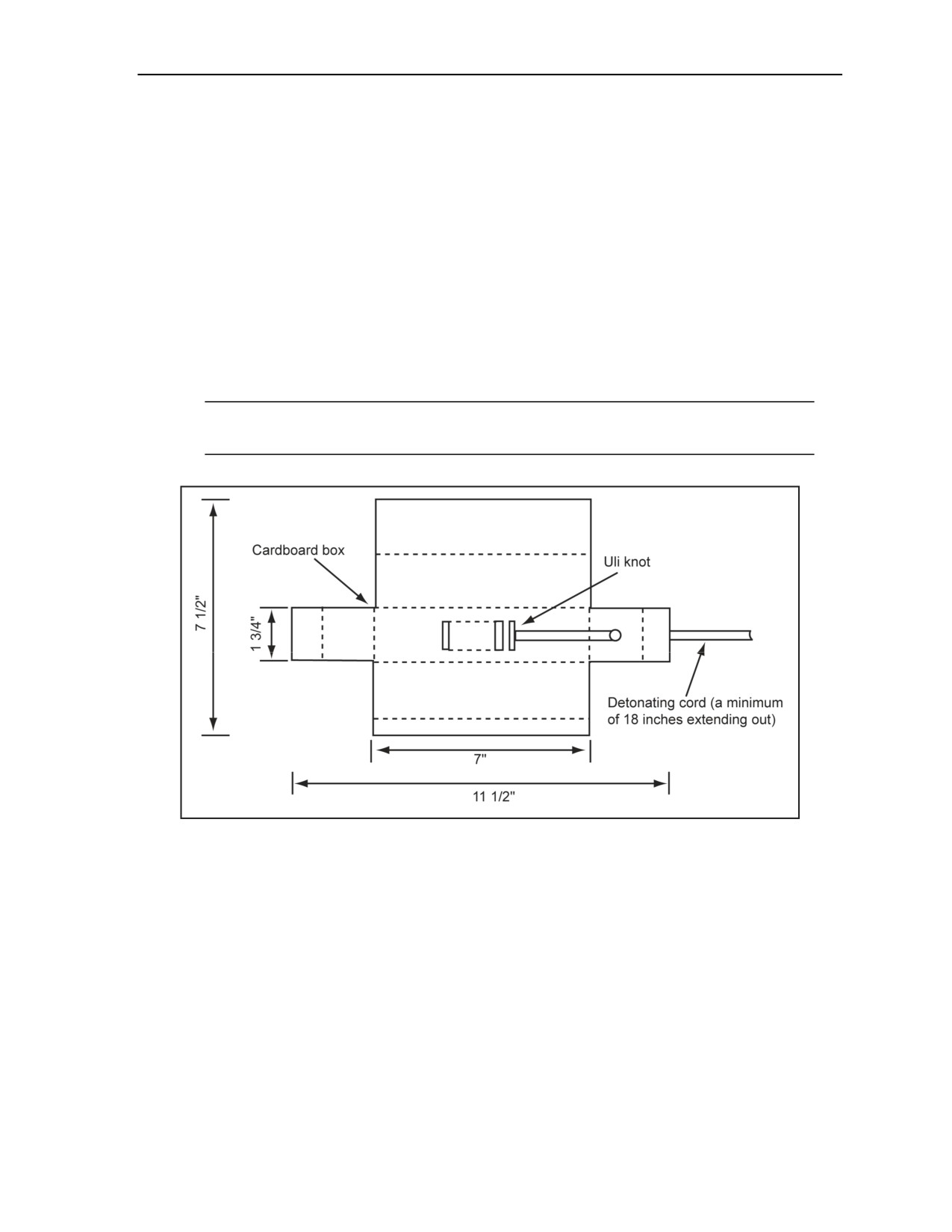
Step 1. Assemble the box by folding along the creases (Figure 5-3).
Step 2. Tape the box to prevent it from unfolding.
Step 3. Fill half of the box with a 50:50 mixture of chalk powder and sand mixture.
Step 4. Tie an Uli knot, and place it in the box.
Step 5. Finish filling the box with the chalk powder and sand mixture.
Step 6. Make a small hole in the top flap.
Step 7. Thread the free end of the detonating cord through the hole at least 18 inches.
Step 8. Close the top flap, and completely tape the outside with olive drab fabric tape.
Step 9. Label each block with a DES label.
Step 10. Place 48 TNT DES devices in each shipping crate.
Step 11. Label each crate.
Note. Omit steps 3 and 5 if using detonating cord as an external primer or if priming with a
nonelectric or electric blasting cap inserted in a cap well.
Figure 5-3. 1-Pound, TNT-Block DES
SPECIFICATIONS
5-49. The 1-pound, TNT-block DES specifications are as follows:
Weight: 1 pound.
Dimensions: 7 by 1 3/4 by 1 3/4 inches.
Packing: 48 blocks per box.
Packing Box: 7 5/8 by 16 1/2 by 12 3/8 inches.
BILL OF MATERIALS
5-50. The BOM for a 1-pound, TNT-block DES is shown in Table 5-3, page 5-12.
11 July 2007
FM 3-34.214
5-11

Chapter 5
Table 5-3. BOM for a 1-Pound TNT-Block DES
Material
Quantity
Cardboard box
1 ea
Detonating cord
4 ft
50:50 mixture of chalk powder and sand
1 lb
Olive drab fabric tape
4 ft
DES label
1 ea
M5A1 (DEMOLITION) BLOCK CHARGE EFFECTS SIMULATOR
5-51. The M5A1 (demolition) block charge DES is a rectangular cardboard box filled with 2 1/2 pounds of
chalk powder and sand mixture. This device can be made with or without an internal detonating cord
booster.
PRIMARY USES
5-52. The M5A1 charge is used primarily for the following:
Demolishing bridges.
Breaching.
Neutralizing mines.
Reducing fortifications.
Cutting timber.
ASSEMBLY INSTRUCTIONS
5-53. The following steps should be used to assemble M5A1 demolition-block DESs:
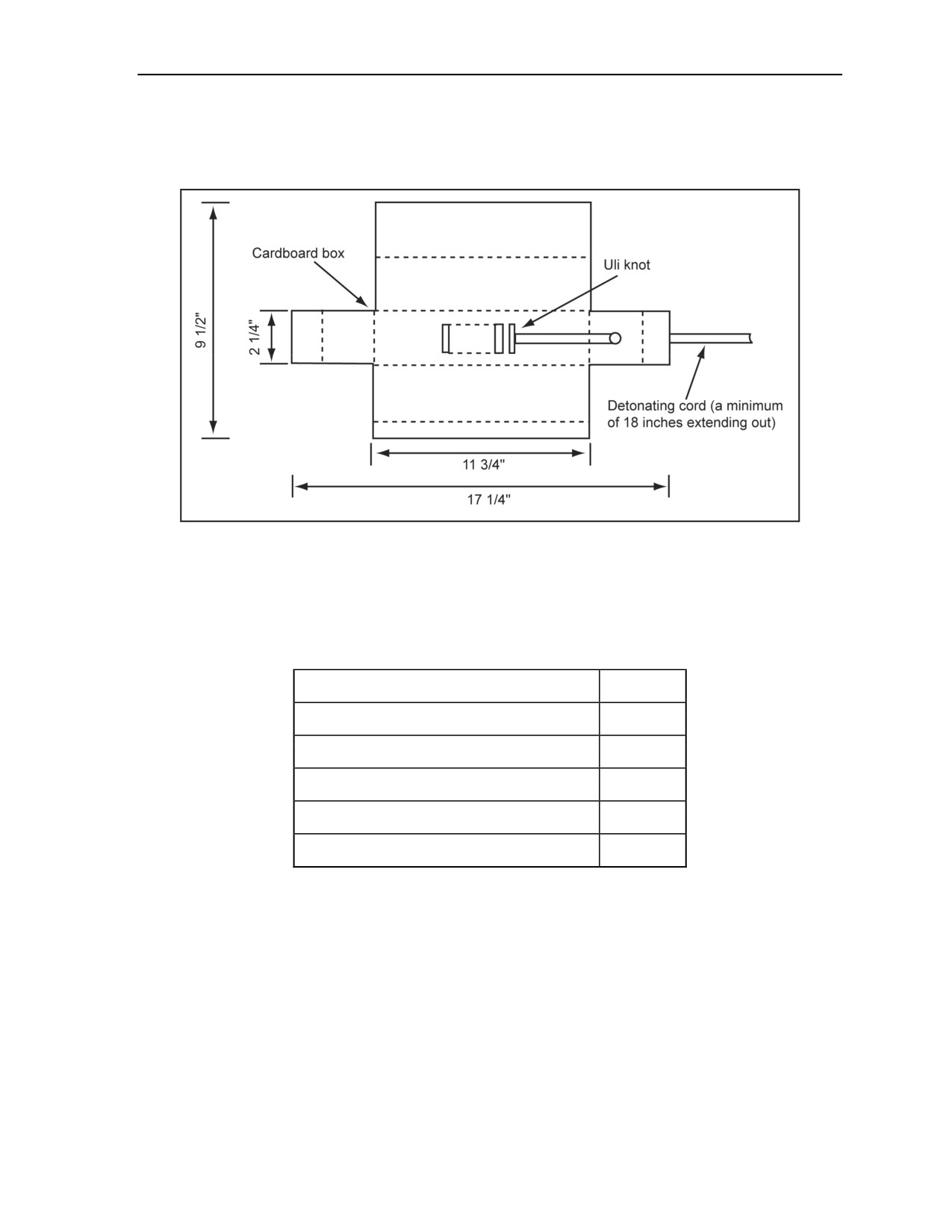
Step 1. Assemble the box by folding along the creases (Figure 5-4).
Step 2. Tape the box to prevent it from folding.
Step 3. Fill half of the box with a 50:50 mixture of chalk powder and sand mixture.
Step 4. Tie an Uli knot, and place it in the box.
Step 5. Finish filling the box with the chalk powder and sand mixture.
Step 6. Make a small hole in the top flap.
Step 7. Thread the free end of the detonating cord through the hole at least 18 inches.
Step 8. Close the top flap, and completely tape the outside with olive drab fabric tape.
Step 9. Label each block with a DES label.
Step 10. Place 24 demolition blocks in each container.
Step 11. Label each container.
Note. Omit steps 4 and 5 if using detonating cord as an external primer or when priming with a
nonelectric or electric blasting cap inserted in a cap well.
SPECIFICATIONS
5-54. The M5A1 demolition-block DES specifications are as follows:
Weight: 2 1/2 pounds.
5-12
FM 3-34.214
11 July 2007
Demolition Operations and Training
Dimensions: 11 3/4 by 2 1/4 by 2 1/4 inches.
Packaging: 24 blocks per container.
Container: 12 1/2 by 14 1/4 by 9 1/2 inches.
Figure 5-4. M5A1 (Demolition) Block DES
BILL OF MATERIALS
5-55. The BOM for an M5A1 demolition block DES is shown in Table 5-4.
Table 5-4. BOM for an M5A1 Demolition Block DES
Material
Quantity
Cardboard box
1 ea
Detonating cord
4 ft
50:50 mixture of chalk powder and sand
2 1/2 lb
Olive drab fabric tape
5 ft
DES label
1 ea
M183 DEMOLITION-SATCHEL CHARGE DEMOLITION EFFECTS
SIMULATOR
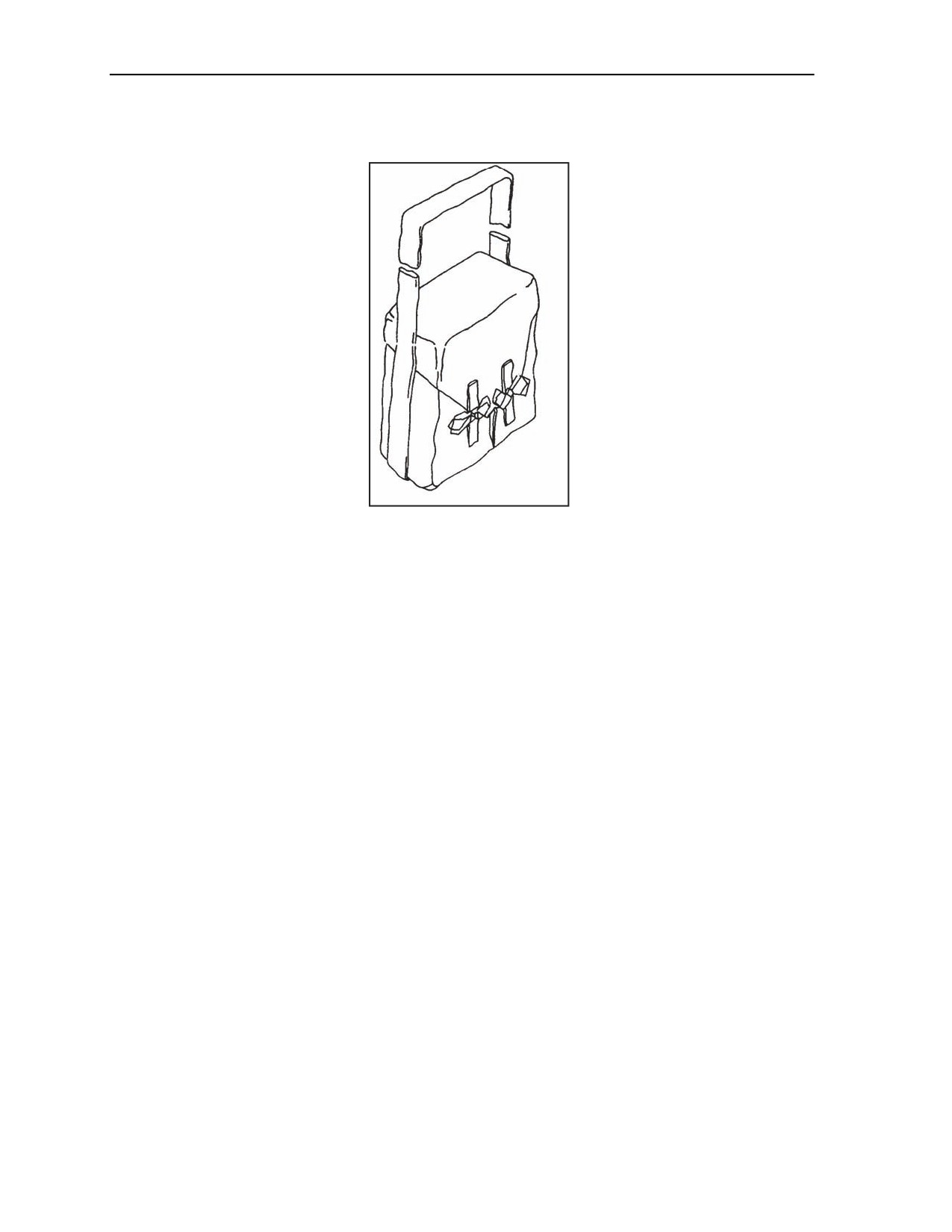
5-56. The M183 demolition-satchel charge assembly DES, or satchel charge, consists of eight M5A1 DES
blocks. The blocks come in two sandbags, four blocks per bag. The two bags come in an M85 canvas
carrying case (Figure 5-5, page 5-14). Two M85 cases come in a wooden box.
PRIMARY USES
5-57. This charge is used primarily for—
Breaching.
Demolishing bridges.
11 July 2007
FM 3-34.214
5-13
Chapter 5
Reducing fortifications.
Destroying cache sites.
Figure 5-5. Filled M85 Carrying Case
ASSEMBLY INSTRUCTIONS
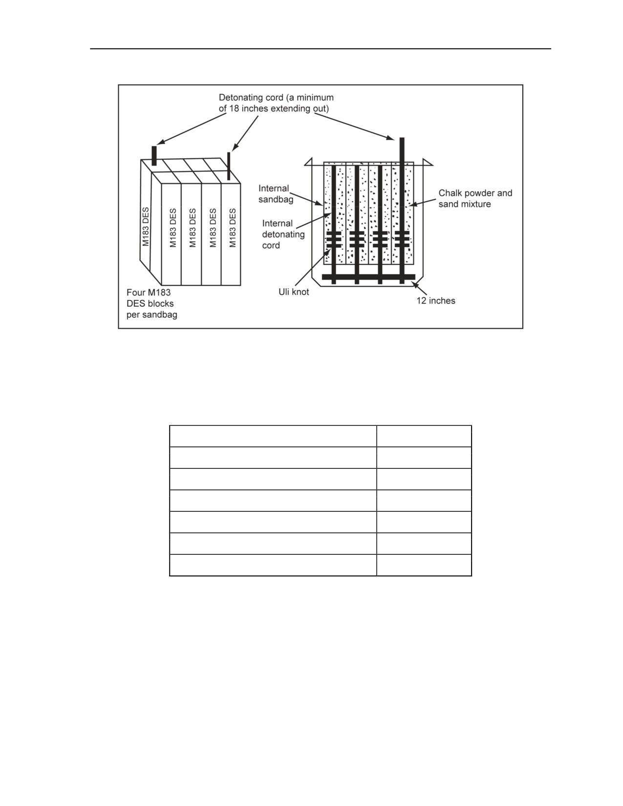
5-58. The following steps should be used to assemble M183 satchel-charge assembly DESs:
Step 1. Construct four M5A1 DES demolition blocks using the assembly instructions for the
M5A1 in paragraph 5-38, page 5-8, except for having an 8-inch tail of detonating cord coming
out the bottom. Ensure that only one of the blocks has the 18-inch length of cord extending out
of the top; trim all others evenly with the top of the box and tape shut.
Step 2. Tape the four M5A1 demolition blocks DES together.
Step 3. Cut and place 12 inches of detonating cord along the bottom end of the M5A1 blocks
(Figure 5-6).
Step 4. Tape or tie the 8-inch tails of the M5A1 blocks to the 12-inch detonating cord along the
bottom.
Step 5. Trim off and tape all detonating cord ends.
Step 6. Place the four demolition blocks in a sandbag that has been cut or rolled back, exposing
the top edge of the four blocks (Figure 5-6).
Step 7. Repeat steps 1 through 6 for the second half of the M183.
Step 8. Place the two complete sandbags into the canvas satchel charge bag, and tie it shut.
Step 9. Place a DES label on the satchel charge.
Step 10. Place two satchel charges in each shipping container.
Step 11. Label each container.
SPECIFICATIONS
5-59. The M183 demolition-satchel charge DES specifications are as follows:
Weight: 20 pounds.
Dimensions: 12 3/4 by 10 1/4 by 4 7/8 inches.
Packaging: Two satchel charges per container.
Container: 13 1/4 by 10 3/4 by 11 1/4 inches.
5-14
FM 3-34.214
11 July 2007
Demolition Operations and Training
Figure 5-6. M183 Satchel Charge DES
BILL OF MATERIALS
5-60. The BOM for an M183 demolition-satchel charge DES is shown in Table 5-5.
Table 5-5. BOM for an M183 Demolition-Satchel Charge DES
Material
Quantity
M112 demolition blocks
16 ea
M85 canvas bag
1 ea
Detonating cord
4 ft
Fabric tape
48 in
Sandbag
2 ea
DES label
1 ea
M2A3 15-POUND, SHAPED CHARGE DEMOLITION EFFECTS
SIMULATOR
5-61. This charge is made of one steel, shaped charge training aid filled with 1 1/2 pounds of chalk powder
and sand mixture. The mixture is placed in a 10-inch-long by 2 1/8-inch (outside) diameter cardboard tube.
Detonating cord is used as the propellant. The cardboard tube is inserted in the middle of the training
device with 18 inches of detonating cord extending out through the top of the device.
PRIMARY USES
5-62. This charge is primarily used for the following:
Cratering.
11 July 2007
FM 3-34.214
5-15
Chapter 5
Destroying abutments.
ASSEMBLY INSTRUCTIONS
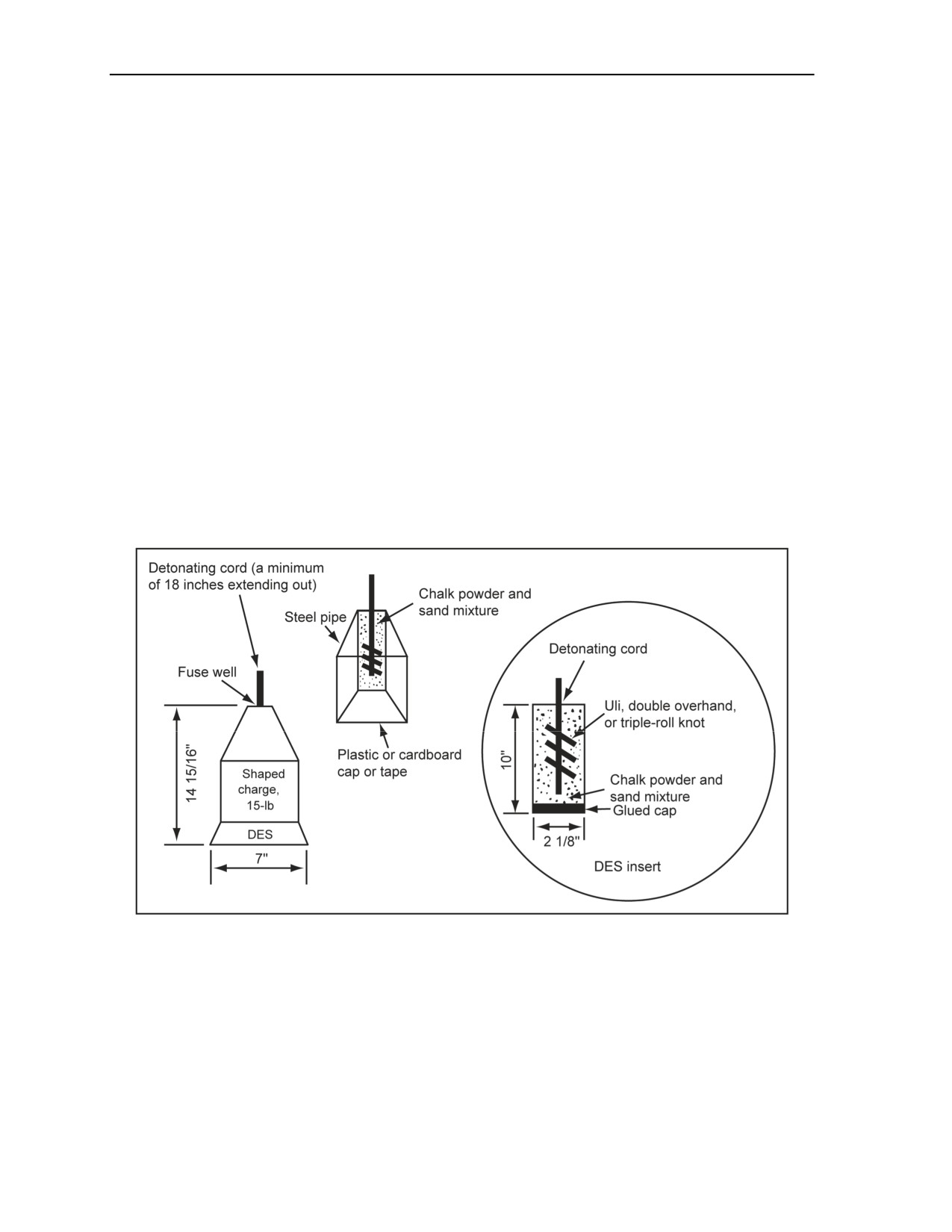
5-63. The following steps should be used to assemble M2A3 15-pound, shaped charge DESs:
Step 1. Cut the cardboard tube insert (10 inches), and glue a plastic cap on one end (Figure 5-7).
Allow it to dry.
Step 2. Fill half of the tube with a 50:50 mixture of chalk powder and sand mixture.
Step 3. Tie an Uli knot or double-overhand knot in 36 inches of detonating cord. Place the knot
inside the tube (Figure 5-7). Finish filling the tube with the chalk powder and sand mixture.
Step 4. Cut a 1/8-inch hole in the center of a second plastic cap.
Step 5. Thread the detonating cord through the hole in the cap with a minimum of 18 inches
extending out.
Step 6. Glue the cap on the open end of the tube, and allow it to dry.
Step 7. Place tape over the free-running end of the detonating cord.
Step 8. Place the cardboard tube into the steel, shaped charge training device, threading the
detonating cord up through the fuse well at least 18 inches (Figure 5-7).
Step 9. Tape the end of the detonating cord to the charge.
Step 10. Label each charge with a DES label.
Step 11. Place three DES shaped charges into an old shipping container, or place four charges if
using a new container.
Step 12. Label the container.
Figure 5-7. 15-Pound, Shaped Charge DES
SPECIFICATIONS
5-64. The M2A3 15-pound, shaped charge DES specifications are as follows:
Weight: 15 pounds.
Dimensions: 14 15/16 by 7 inches.
Packing: Old container, three charges; new container, four charges.
5-16
FM 3-34.214
11 July 2007

Demolition Operations and Training
BILL OF MATERIALS
5-65. The BOM for an M2A3 15-pound, shaped charges is shown in Table 5-6.
Table 5-6. BOM for an M2A3 15-Pound, Shaped Charge DES
Material
Quantity
M2A3 steel, shaped charge DES
1 ea
Cardboard tube
1 ea
Detonating cord
4 ft
50:50 mixture of chalk powder and sand
1.5 lb
Plastic cap
2 ea
Glue
1 container
Fabric tape
4 ft or 2 ea
DES label
1 ea
M3 40-POUND, SHAPED CHARGE DEMOLITION EFFECTS
SIMULATOR
5-66. This charge is made of one steel, shaped charge training aid filled with 1 1/2 pounds of chalk. The
chalk is placed into an 11- by 2 1/8-inch (outside) diameter cardboard tube. A detonating cord is used as the
propellant. The cardboard tube is inserted into the middle of the training device with
18 inches of
detonating cord extending out through the top of the device.
PRIMARY USES
5-67. This charge is used primarily for the following:
Cratering.
Destroying abutments.
ASSEMBLY INSTRUCTIONS
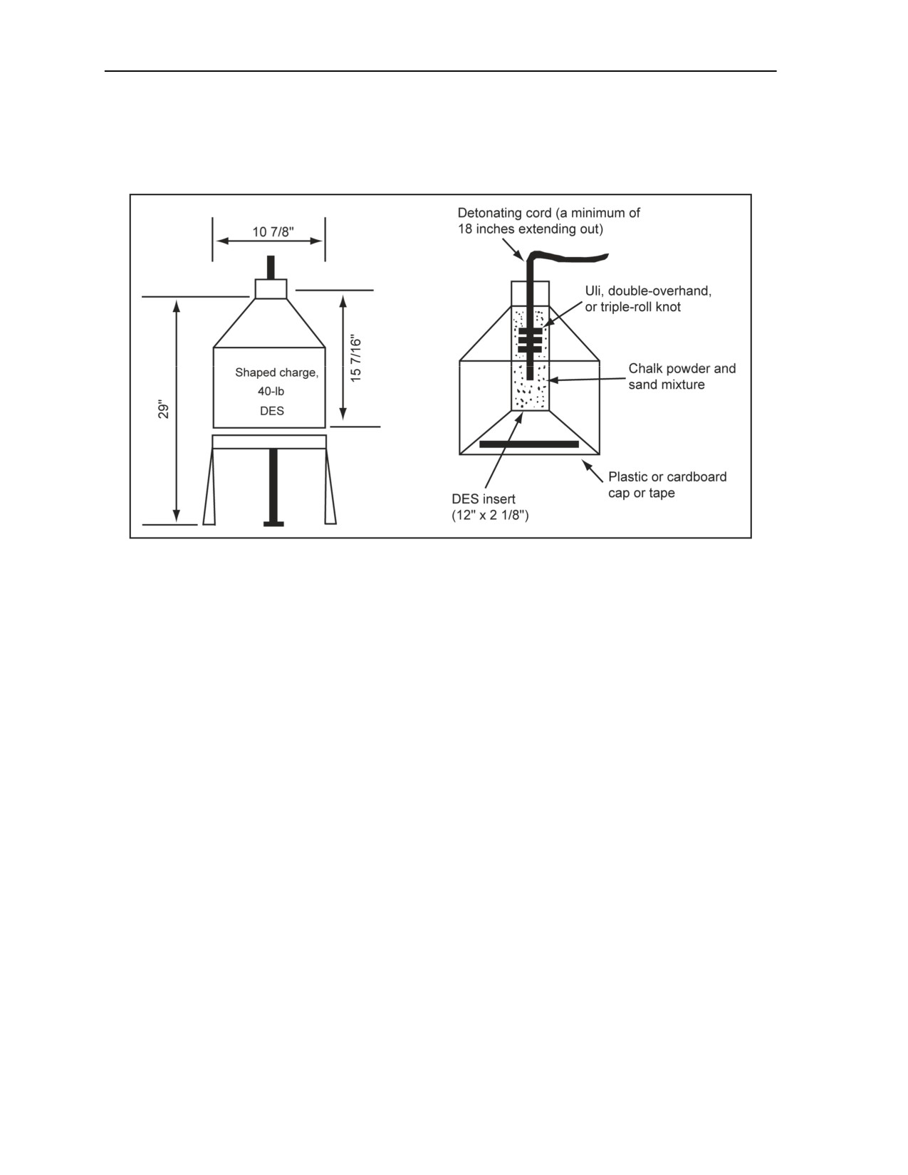
5-68. The following steps should be used to assemble M3 40-pound, shaped charge DESs:
Step 1. Cut a cardboard tube insert (12 inches), and glue a plastic cap on one end (Figure 5-8,
page 5-18). Allow it to dry.
Step 2. Fill half of the tube with a 50:50 mixture of chalk powder and sand mixture.
Step 3. Tie an Uli knot or a double-overhand knot in 36 inches of detonating cord, and place the
knot inside the tube.
Step 4. Finish filling the tube with the chalk powder and sand mixture (Figure 5-8).
Step 5. Cut a 1/8-inch hole in the center of a second plastic cap.
Step 6. Thread the detonating cord through the hole in the cap with a minimum of 18 inches
extending out.
Step 7. Glue the cap on, and allow it to dry.
Step 8. Place tape over the free-running end of the detonating cord.
Step 9. Place the cardboard tube into the steel, shaped charge training device, threading the
detonating cord up through the fuse well at least 18 inches (Figure 5-8).
11 July 2007
FM 3-34.214
5-17
Chapter 5
Step 10. Tape the bottom end of the detonating cord to the charge.
Step 11. Label each charge with a DES label.
Step 12. Place one DES shaped charge in each shipping container.
Step 13. Label each container.
Figure 5-8. 40-Pound, Shaped Charge DES
SPECIFICATIONS
5-69. The M3 40-pound, shaped charge DES specifications are as follows:
Weight: 40 pounds.
Dimensions: 15 7/16 by 10 7/8 inches.
Packing: One per container.
BILL OF MATERIALS
5-70. The BOM for a M3 40-pound, shaped charge DES is shown in Table 5-7.
5-18
FM 3-34.214
11 July 2007

Demolition Operations and Training
Table 5-7. BOM for a 40-Pound, Shaped Charge DES
Material
Quantity
M3 steel, shaped charge, DES
1 ea
Cardboard tube
1 ea
Detonating cord
4 ft
50:50 mixture of chalk powder and sand
10 lb
Glue
1 container
Fabric tape or plastic cap
4 ft or 2 ea
DES label
1 ea
40-POUND, CRATERING CHARGE DEMOLITION EFFECTS
SIMULATOR
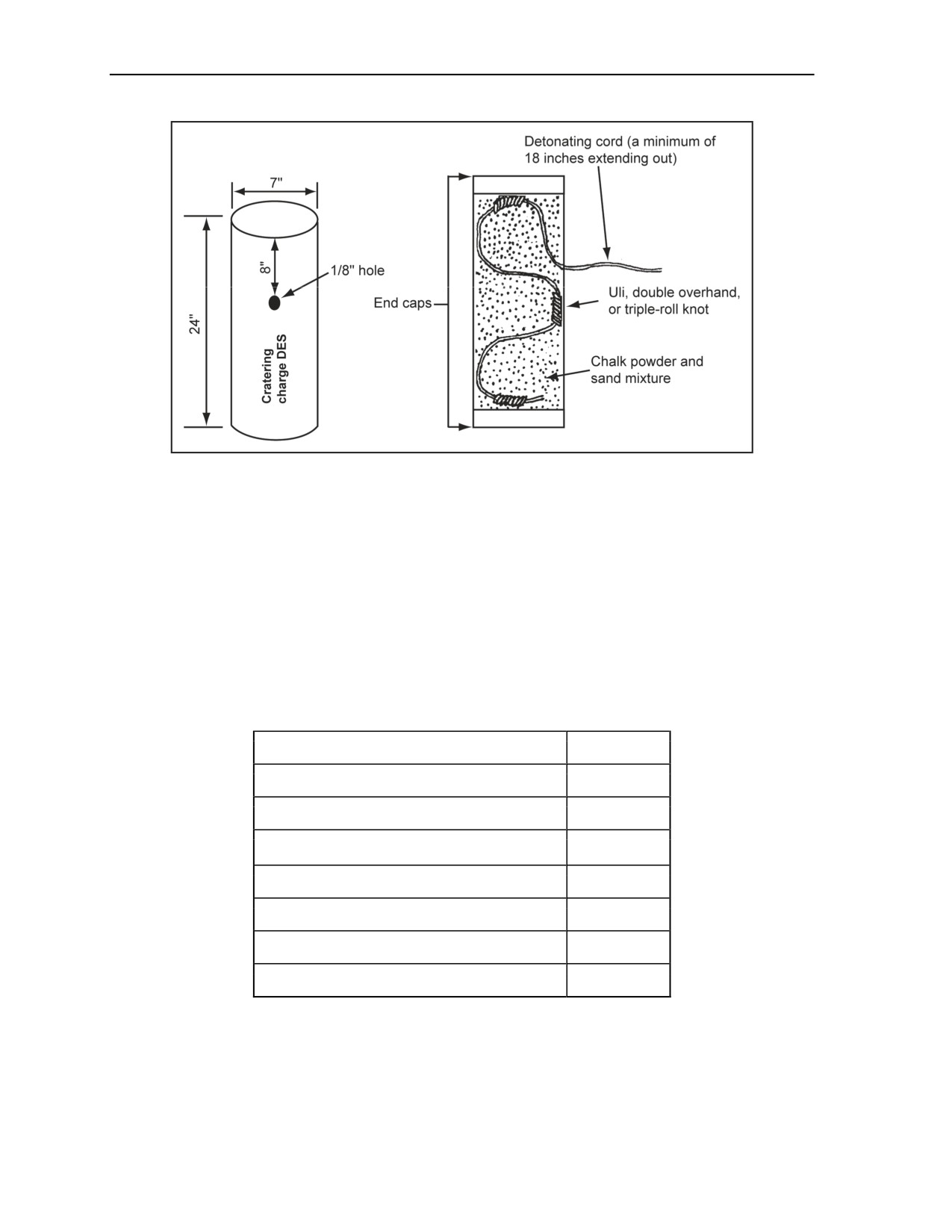
5-71. This charge is made of a cardboard tube, 24 inches long by 7 inches in diameter, filled with about
40 pounds of chalk powder and sand mixture. Detonating cord is used internally as the basic propellant
charge.
PRIMARY USES
5-72. This charge is used primarily for the following:
Cratering.
Destroying abutments.
ASSEMBLY INSTRUCTIONS
5-73. The following steps should be used to assemble 40-pound, cratering charge DESs:
Step 1. Glue a plastic cap in the bottom of the cardboard tube, and allow it to dry.
Step 2. Cut a 1/8-inch hole about 8 inches from the top of the tube (Figure 5-9, page 5-20).
Step 3. Tie three Uli knots or a double-overhand knot about 10 inches apart in a length of
detonating cord, leaving about 18 inches after the last knot (Figure 5-9).
Step 4. Place the first knot along the bottom of the tube.
Step 5. Tape the remaining knots to the inside of the tube, ensuring that the detonating cord does
not cross over itself.
Step 6. Fill the tube halfway with the chalk powder and sand mixture.
Step 7. Thread the running end of the detonating cord through the 1/8-inch hole (Figure 5-9).
Ensure that at least 18 inches of detonating cord extends out of the hole.
Step 8. Finish filling the tube with the chalk powder and sand mixture. Use a scale to ensure the
proper weight.
Step 9. Glue a plastic end cap in the top of the tube.
Step 10. Place a DES label on the tube.
Step 11. Place one DES 40-pound cratering charge in each shipping container.
Step 12. Label each container.
11 July 2007
FM 3-34.214
5-19
Chapter 5
Figure 5-9. 40-Pound, Cratering Charge DES
SPECIFICATIONS
5-74. The 40-pound, cratering charge DES specifications are as follows:
Weight: 40 pounds.
Dimensions: 24 by 7 inches.
Packing: One charge per box.
BILL OF MATERIALS
5-75. The BOM for a 40 pound, cratering charge DES is shown in Table 5-8.
Table 5-8. BOM for a 40-Pound, Cratering Charge DES
Material
Quantity
Cardboard tube
1 ea
Detonating cord
8 ft
50:50 mixture of chalk powder and sand
40 lb
Plastic bag
1 ea
Plastic end cap
2 ea
Glue
1 container
DES label
1 ea
BANGALORE TORPEDO DEMOLITION EFFECTS SIMULATOR
5-76. The bangalore torpedo DES is made of a 5-foot-long by 2 1/8-inch-diameter cardboard tube filled
with about 15 pounds of chalk powder and sand mixture. Detonating cord is used for the internal booster
charge.
5-20
FM 3-34.214
11 July 2007

Demolition Operations and Training
PRIMARY USES
5-77. The bangalore torpedo DES is used primarily clearing the following:
Wire obstacles.
AP minefields.
ASSEMBLY INSTRUCTIONS
5-78. The following steps should be used to assemble bangalore torpedo DESs:
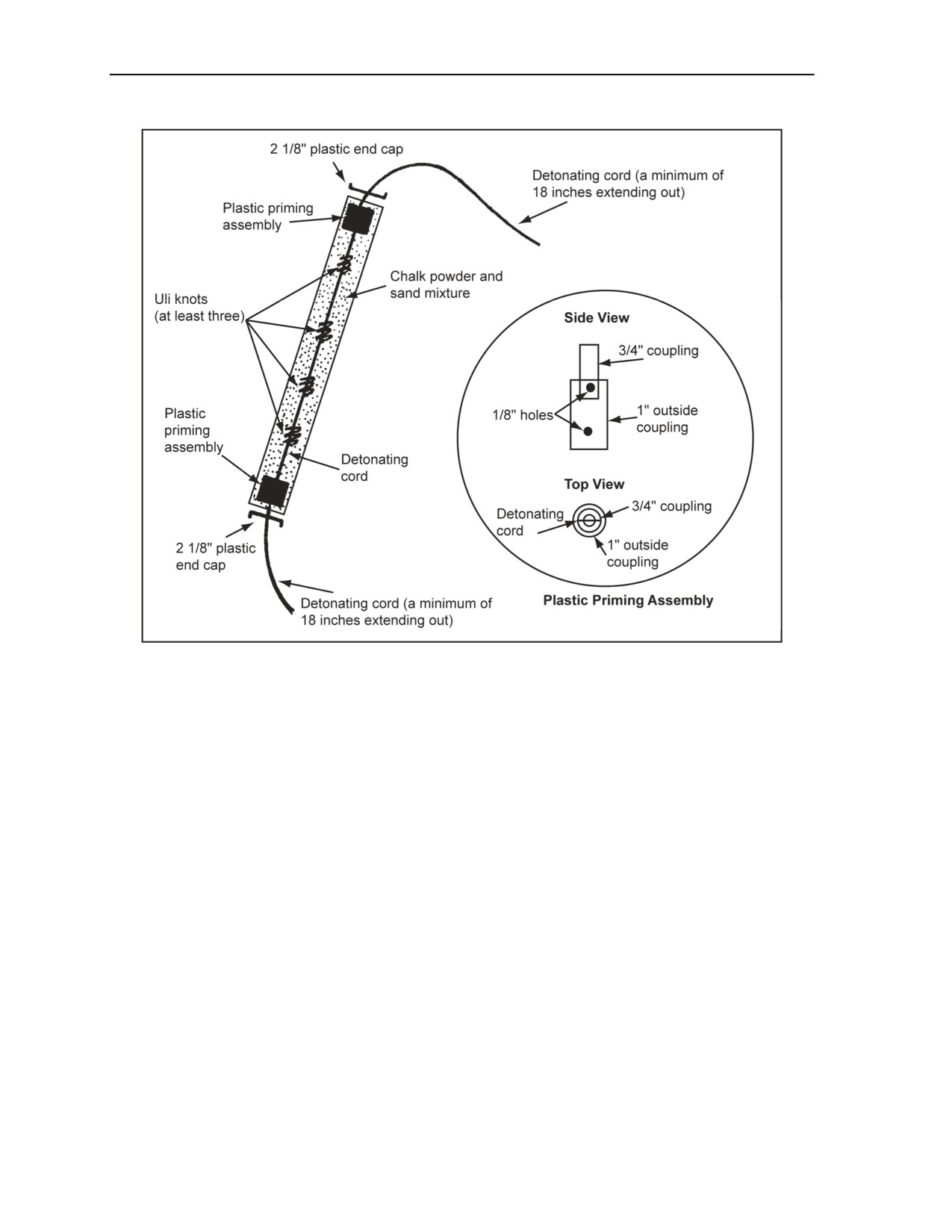
Step 1. Tie at least three Uli knots, equally spaced, in an 18-foot length of detonating cord
(Figure 5-10, page 5-22).
Step 2. Thread the detonating cord through the 5-foot cardboard tube, leaving equal amounts
extending out of each end.
Step 3. Take a 2-inch-long by 1-inch-diameter plastic plumber’s coupling, and drill two 1/8-inch
holes completely through the coupling at half an inch from each end.
Step 4. Thread the running end of the detonating cord through the two holes at the top. Wrap the
cord around the coupling five times, and tape it in place.
Step 5. Thread the detonating cord through one of the holes at the bottom of the coupling.
Step 6. Pass the detonating cord through both holes of the 3/4-inch plastic coupling, and tape it
down.
Step 7. Insert the 3/4-inch coupling into the 1-inch coupling (Figure 5-10).
Step 8. Insert the coupling assembly into the cardboard tube, keeping it flush with the end of the
tube.
Step 9. Wrap the assembly with fabric tape to keep a tight fit in the main tube.
Step 10. Cut an eyelet in the plastic end cap, and glue it into the end of the tube.
Step 11. Gently pull any of the slack out of the detonating cord through the opposite end of the
cardboard tube.
Step 12. Fill the tube with 15 pounds of 50:50 mixture of chalk powder and sand.
Step 13. Repeat steps 3 through 8 at the other end.
Step 14. Cut an eyelet in the plastic end cap, and glue it into the end of the tube.
Step 15. Label all DES tubes.
Step 16. Box 10 tubes per shipping container. Label each container.
11 July 2007
FM 3-34.214
5-21
Chapter 5
Figure 5-10. Bangalore Torpedo DES
SPECIFICATIONS
5-79. The bangalore torpedo DES specifications are as follows:
Weight: 15 pounds.
Dimensions: 5 feet by 2 1/8 inches in diameter.
Packing: 10 tubes per shipping container.
5-22
FM 3-34.214
11 July 2007

Demolition Operations and Training
BILL OF MATERIALS
5-80. See Table 5-9. The BOM for a bangalore torpedo DES is shown in Table 5-9.
Table 5-9. BOM for a Bangalore Torpedo DES
Material
Quantity
Cardboard tube, 5-ft by 2 1/8-in diameter
1 ea
Detonating cord
18 ft
Plastic coupling (1 in)
2 ea
Plastic coupling (3/4 in)
2 ea
Plastic end cap
2 ea
50:50 mixture of chalk powder and sand
15 lb
Glue
6 oz
Fabric tape
2 ft
DES label
1 ea
M1 MILITARY DYNAMITE DEMOLITION EFFECTS SIMULATOR
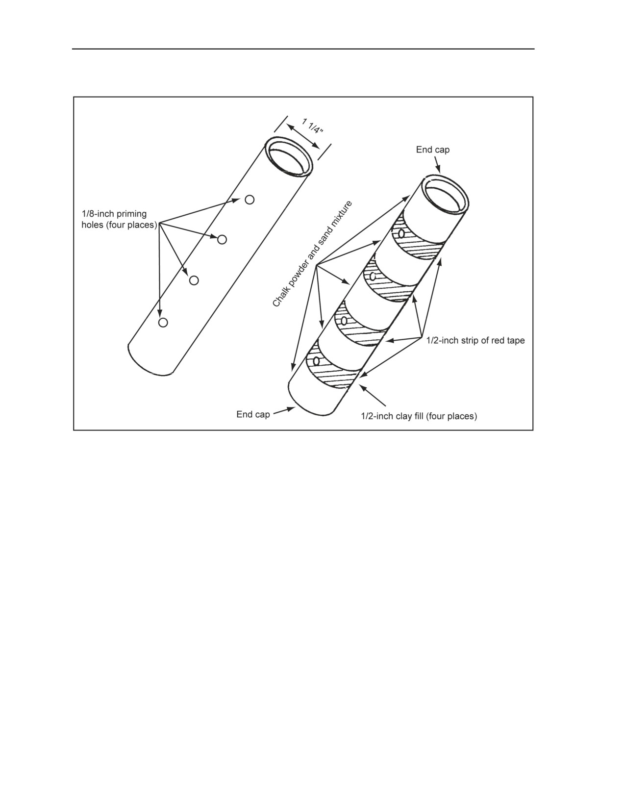
5-81. The M1 military dynamite DES is an 8- by 1 1/4-inch cardboard tube filled with 1/2 pound of chalk
powder and sand mixture. The device has no internal detonating cord.
PRIMARY USES
5-82. The military dynamite DES is used primarily for the following:
Cratering.
Removing stumps.
Breaching.
ASSEMBLY INSTRUCTIONS
5-83. The following steps should be used to prime with an MDI:
Step 1. Glue an end cap into one end of the tube, and allow it to dry.
Step 2. Punch four 1/8-inch priming holes through both sides of the tube at designated locations
(Figure 5-11, page 5-24).
Step 3. Fill the tube up almost to the first hole with the chalk powder and sand mixture.
Step 4. Tamp a 1/2-inch piece of clay fill on top of the chalk powder and sand mixture past the
first hole.
Step 5. Fill the tube with the chalk powder and sand mixture almost up to the next hole.
Step 6. Tamp a 1/2-inch piece of pottery clay into the tube past the second hole.
Step 7. Repeat the process for the third and fourth holes.
Step 8. Glue the second end cap in place, and allow it dry.
Step 9. Tape the tube with olive drab fabric tape.
Step 10. Tape the holes with a 1/2-inch strip of red tape.
Step 11. Label with a DES label.
Step 12. Package 100 per shipping container.
11 July 2007
FM 3-34.214
5-23
Chapter 5
Step 13. Label each container.
Figure 5-11. M1 Military Dynamite DES
5-84. The following assembly instructions should be used for priming with a blasting cap instead of
detonating cord:
Step 1. Glue an end cap into one end of the tube, and allow it to dry.
Step 2. Fill the tube with the chalk powder and sand mixture.
Step 3. Glue the second end cap in place, and allow it dry.
Step 4. Tape the tube with olive drab fabric tape.
Step 5. Label with a DES label.
Step 6. Package 100 per shipping container.
Step 7. Label each container.
SPECIFICATIONS
5-85. The M1 military dynamite DES specifications are as follows:
Weight: 1/2 pound.
Dimensions: 8 by 1 1/4 inches.
Packing: 100 per box.
BILL OF MATERIALS
5-86. The BOM for an M1 military dynamite DES is shown in Table 5-10.
5-24
FM 3-34.214
11 July 2007

Demolition Operations and Training
Table 5-10. BOM for an M1 Military Dynamite DES
Material
Quantity
Cardboard tube, 8-in by 1 1/4-in diameter
1 ea
50:50 mixture of chalk powder and sand
8 oz
Clay fill, pottery
6 oz
End cap
2 ea
Glue
3 oz
Olive drab fabric tape
2 ft
Red fabric tape
6 in
DES label
1 ea
SECTION IV - PRIMING METHODS
5-87. This section covers priming methods for each DES device. Using detonating cord as the propellant
charge in the DES system requires modifications to the normal priming sequence. Efforts are being made to
correct these minor deficiencies. (See Chapter 2 for assembly instructions for initiating sets.) DES devices
are primed with detonating cord, a nonelectric blasting cap, or an electric blasting cap. Detonating cord
priming is the preferred method for priming DES charges since it involves fewer blasting caps, makes
priming and misfire investigation safer, and allows charges to be primed at state of readiness—state 1 (safe)
when in place on a reserved demolition. DESs can be primed with or without internal detonating cord
boosters.
Note. A 6-inch length of detonating cord equals the power output of a blasting cap. However,
detonating cord will not detonate explosives as reliably as a blasting cap because its power is not
as concentrated. Therefore, always use several turns or a knot of detonating cord for priming
charges.
DEMOLITION EFFECTS SIMULATORS WITHOUT INTERNAL
DETONATING CORD BOOSTERS
5-88. These DESs are primarily chalk powder and sand mixture filled devices, except for the sheet
explosive and M112 DESs, which are made from rubber matting and moist clay fill. They have priming
procedures identical to real explosive devices, which are primed with the detonating cord. The paragraphs
below contain priming instructions for the following DESs:
Sheet explosive.
M112 (composition C4) block.
1-pound TNT block or one M5A1 demolition block.
M1 military dynamite.
SHEET EXPLOSIVE DEMOLITION EFFECTS SIMULATOR
5-89. Priming instructions for the sheet explosive DES are discussed in the paragraphs below. Discussed is
the use of detonating cord and MDIs.
11 July 2007
FM 3-34.214
5-25
Chapter 5
Detonating Cord
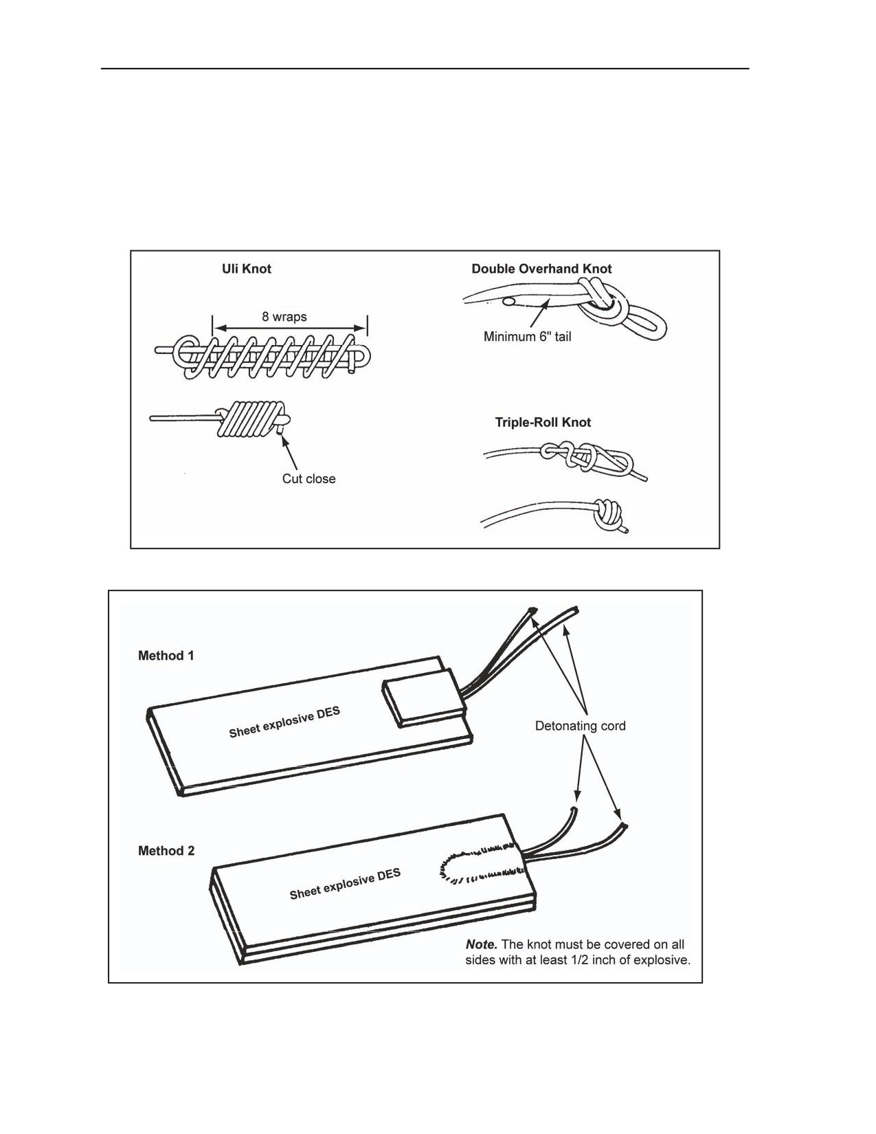
5-90. Either an Uli knot, a double-overhand knot, or a triple-roll knot (Figure 5-12) and one of the
following methods is used to prime sheet explosives:
Method 1. Insert the knot between two sheets of explosive.
Method 2. Place the knot on top of the sheet explosive, and secure it with a small strip of sheet
explosive (Figure 5-13). Strengthen the primed area by wrapping it with green duct tape or
electrical tape.
Figure 5-12. Knots
Figure 5-13. Priming a Sheet Explosive DES With Detonating Cord
5-26
FM 3-34.214
11 July 2007
Demolition Operations and Training
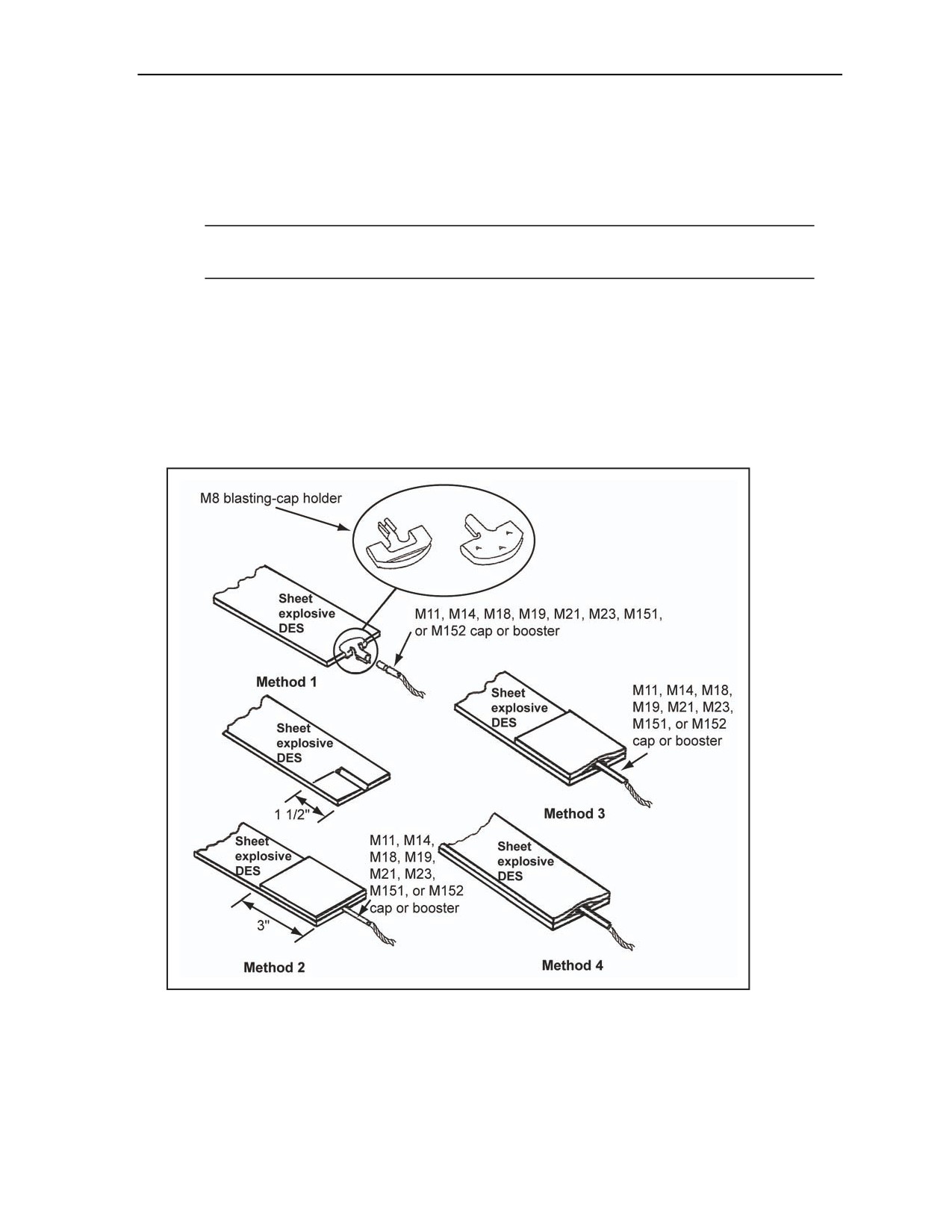
Modernized Demolition Initiator
5-91. To prime sheet explosive DES charges, use Figure 5-14 and one of the following methods:
Method 1. Attach an M8 blasting-cap holder to the end or side of the sheet explosive DES.
Insert an M11, M14, M18, M19, M21, M23, M151, or M152 cap or booster into the holder until
the end of the blasting cap presses against the sheet explosive DES.
Note. The M8 blasting-cap holder has three teeth that prevents the clip from withdrawing from
the explosive; two spring arms firmly hold the M11 cap in the M8 holder.
Method 2. Cut a notch in the sheet explosive DES (about 1 1/2 inches long and 1/4 inch wide).
Insert the M11, M14, M18, M19, M21, M23, M151, or M152 cap or booster to the limit of the
notch. Secure the blasting cap with a strip of sheet explosive and adhesive tape.
Method 3. Place 1 1/2 inches of the M11, M14, M18, M19, M21, M23, M151, or M152 cap or
booster on top of the sheet explosive DES. Secure it with a strip of sheet explosive DES (at least
3 by 3 inches) and adhesive tape.
Method 4. Insert the end of the blasting cap 1 1/2 inches between two sheets of DES sheet
explosive. Wrap the sheets with tape to secure the M11, M14, M18, M19, M21, M23, M151, or
M152 cap or booster.
Figure 5-14. Priming a Sheet Explosive DES With MDI
11 July 2007
FM 3-34.214
5-27
Chapter 5
M112 (COMPOSITION C4) BLOCK DEMOLITION EFFECTS SIMULATOR
5-92. Priming instructions for the M112 (composition C4) block DES are discussed in the paragraphs
below. Discussed is the use of detonating cord and MDIs.
Detonating Cord
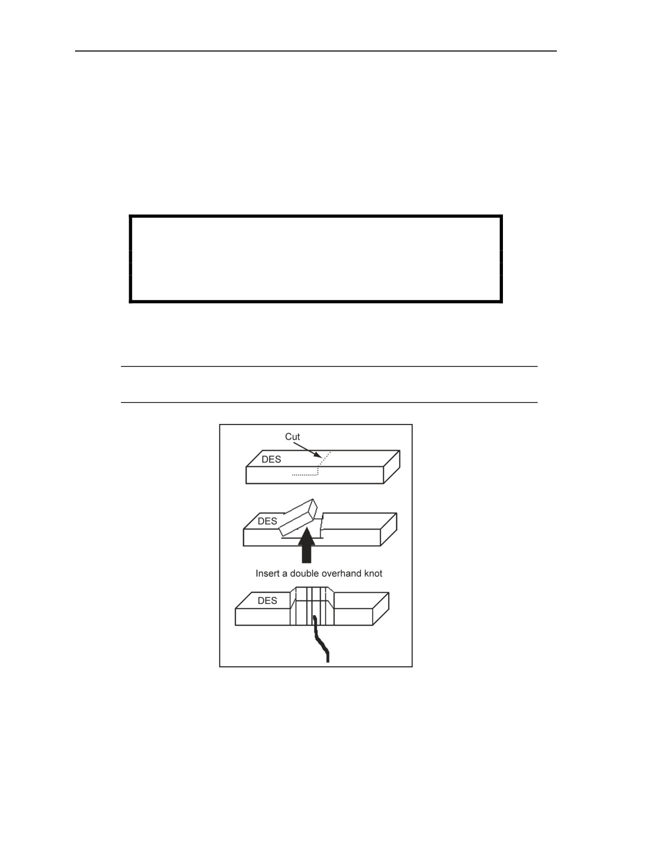
5-93. To prime M112 (composition C4) block DES with detonating cord, use Figure 5-15 and the
following steps:
Step 1. Form either an Uli knot or a triple-roll knot (Figure 5-12, page 5-26).
Step 2. Cut a notch out of the DES large enough to insert the knot that was formed.
WARNING
Use a sharp, nonsparking knife on a nonsparking surface to cut
the explosive. Failure to comply could result in immediate
personal injury or damage to equipment.
Step 3. Place the knot in the cut.
Step 4. Use the clay that was removed from the notch to cover the knot. Ensure that there is at
least 1/2 inch of clay on all sides of the knot.
Step 5. Strengthen the primed area by wrapping it with tape.
Note. It is not recommended that an M112 (composition C4) block DES be primed by wrapping
it with detonating cord, since wraps will not properly detonate the actual explosive charge.
Figure 5-15. Priming an M112 DES With Detonating Cord
5-28
FM 3-34.214
11 July 2007

Demolition Operations and Training
Modernized Demolition Initiator
5-94. M112 (composition C4) block DES does not have a cap well. The following steps are used to make a
cap well and to prime the DES with an M11, M14, M18, M19, M21, M23, M151, or M152 cap or booster:
Step 1. Make a hole in the end or on the side (at the midpoint) with an M2 crimper or other
nonsparking tool that is large enough to hold the blasting cap.
Step 2. Insert the M11, M14, M18, M19, M21, M23, M151, or M152 cap or booster into the
hole or cut. Do not force the cap if the M11, M14, M18, M19, M21, M23, M151, or M152 cap
or booster does not fit the hole or cut—make the hole larger.
Step 3. Anchor the M11, M14, M18, M19, M21, M23, M151, or M152 cap or booster in the
DES block by gently squeezing the clay around the blasting cap.
Step 4. Strengthen the primed area by wrapping it with tape.
1-POUND TRINITROTOLUENE-BLOCK DEMOLITION EFFECTS SIMULATOR AND M5A1
DEMOLITION-BLOCK DEMOLITION EFFECTS SIMULATOR
5-95. The same methods are used to prime both the 1-pound, TNT block DES (only the TNT is shown in
Figure 5-16) and the M5A1 demolition block DES.
Detonating Cord
5-96. DES blocks without internal detonating cord boosters can be primed with detonating cord using
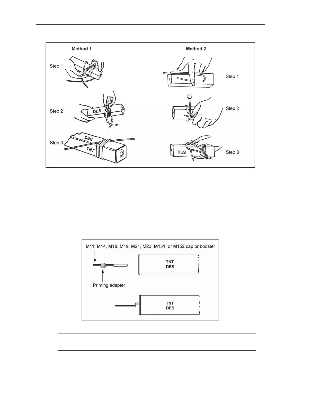
several methods (Figure 5-16, page 5-30). The two standard methods are the—
Common method (method 1). Lay one end (2-foot length) of detonating cord at an angle across
the DES block. Wrap the running end around the block three turns, laying the wraps over the
standing end. Slip the running end (on the forth wrap) under all wraps, parallel to the standing
end, and draw the wraps tight.
Alternate method (method 2). Place a loop of detonating cord on the DES block, leaving
enough length on the end to make four turns around the block and loop. Start the first wrap, and
ensure that you immediately cross over the standing end of the loop, working your way to the
closed end of the loop. Pass the free end of the detonating cord through the loop, and pull it tight
to form a knot around the outside of the block.
11 July 2007
FM 3-34.214
5-29
Chapter 5
Figure 5-16. Priming a TNT Block DES Using Detonating Cord
Modernized Demolition Initiator
5-97. Some TNT or M5A1 DES blocks may have threaded cap wells. If so, use a priming adapter (if
available) to secure the M11, M14, M18, M19, M21, M23, M151, or M152 cap or booster to the DES
block (Figure 5-17). If a priming adapter is not available or the DES block does not have a threaded cap
well, prime without an adapter. If there is no cap well, make one using the following steps:
Step 1. Use M2 crimpers or other nonsparking tools to make a hole in the end. Do not force the
cap if the M11, M14, M18, M19, M21, M23, M151, or M152 cap or booster does not fit the hole
or cut, make the hole larger.
Figure 5-17. Priming a TNT Block DES (With Adapter) Using an MDI
Note. Prepare the initiating set before priming. Cap control must be according to the information
in this manual.
5-30
FM 3-34.214
11 July 2007
Demolition Operations and Training
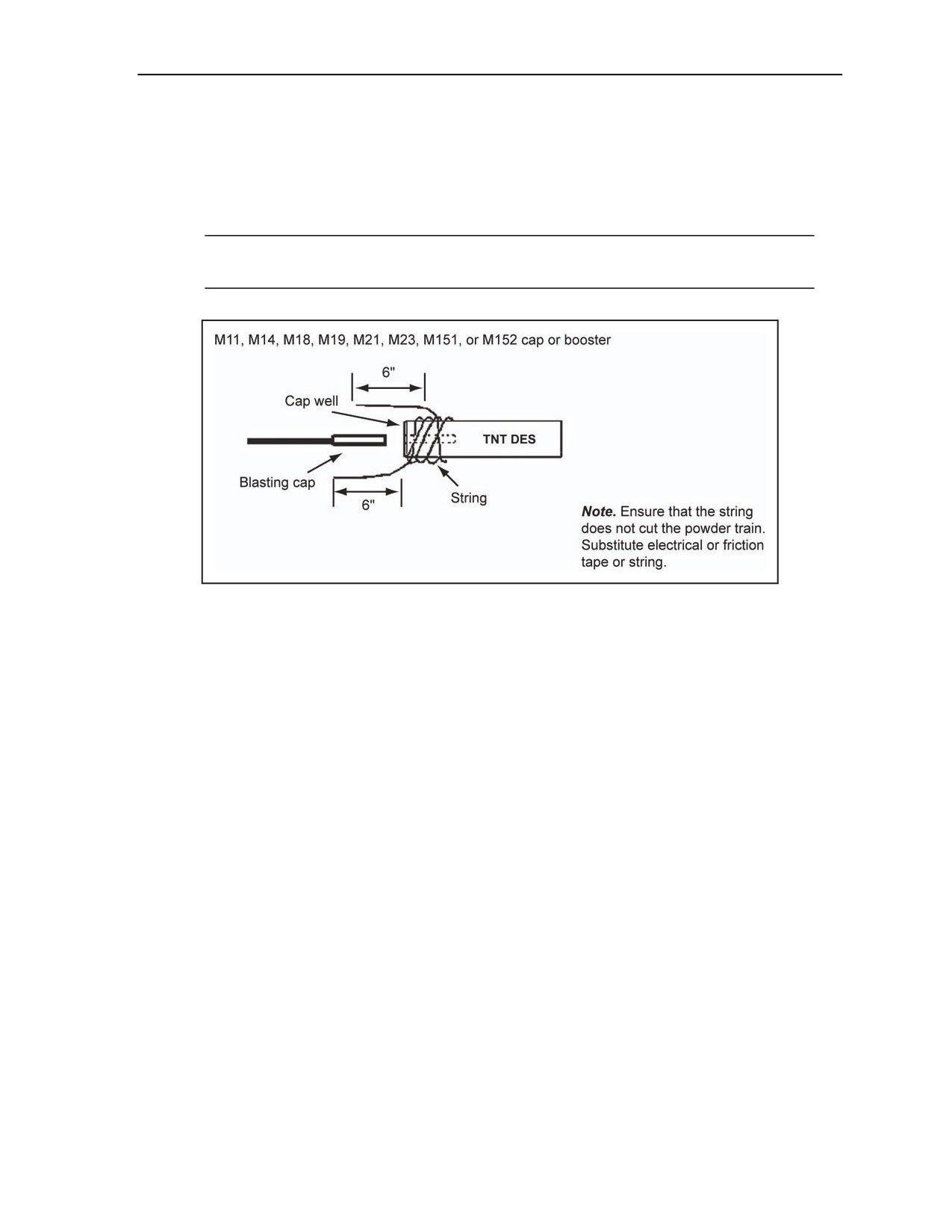
Step 2. Wrap a string tightly around the DES block and tie it securely, leaving about 6 inches of
loose string at each end.
Step 3. Insert the M11, M14, M18, M19, M21, M23, M151, or M152 cap or booster into the cap
well. Make a cap well if there is not one.
Step 4. Tie the loose string around the fuse to prevent the M11, M14, M18, M19, M21, M23,
M151, or M152 cap or booster from separating from the block (Figure 5-18).
Note. Electrical or friction tape can also effectively secure an M11, M14, M18, M19, M21, M23,
M151, or M152 cap or booster in the DES.
Figure 5-18. Priming a TNT DES (Without Adapter) Using an MDI
M1 MILITARY DYNAMITE DEMOLITION EFFECTS SIMULATOR
5-98. Priming instructions for the M1 military dynamite DES is discussed in the paragraphs below.
Discussed is the use of detonating cord and MDIs.
Detonating Cord
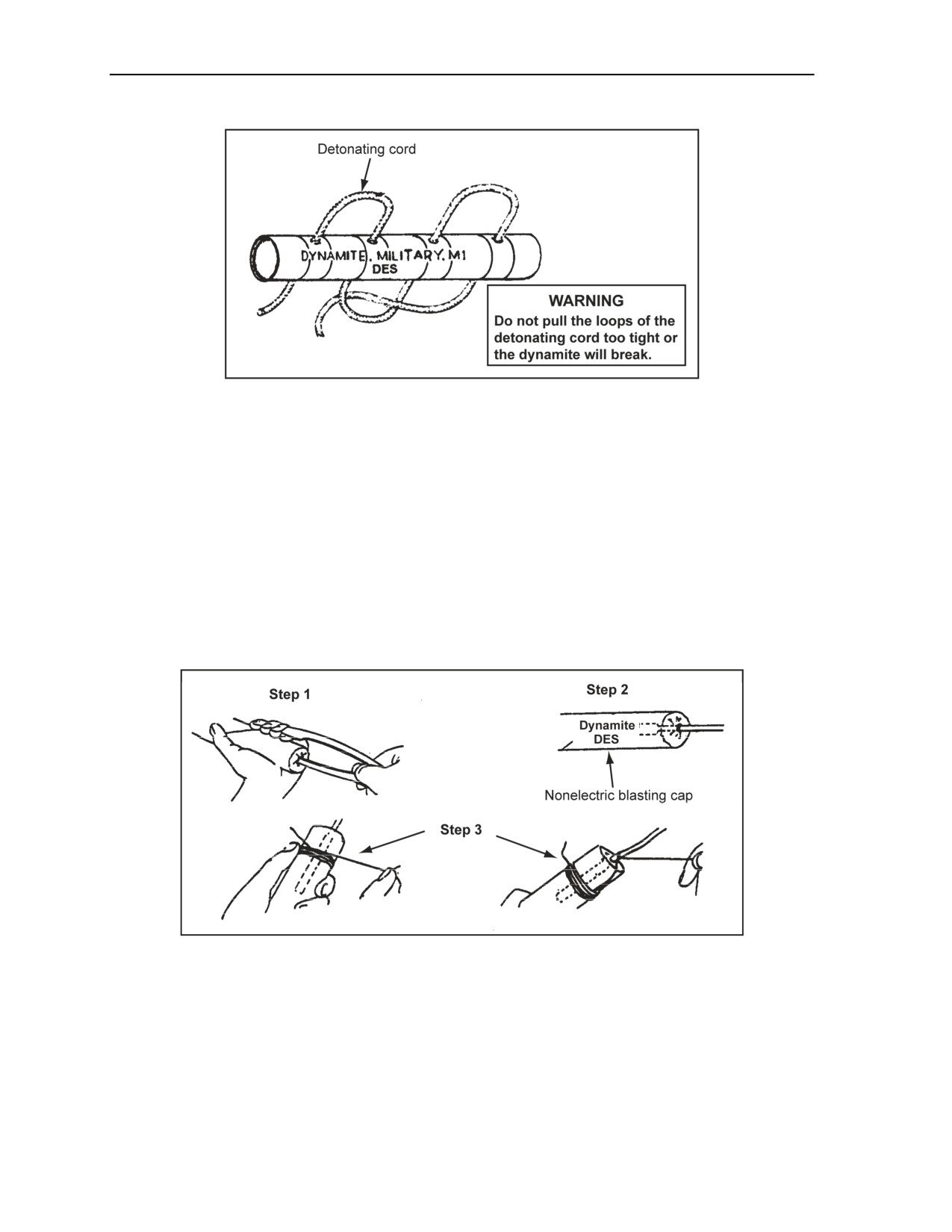
5-99. See Figure 5-19. The following steps and Figure 5-19, page 5-32, are used to prime with detonating
cord:
Step 1. Use M2 crimpers to punch four holes through the DES dynamite cartridge in areas
covered by red tape. Ensure that the DES cartridge is rotated 180° after punching each hole to
keep the holes parallel.
Step 2. Lace the detonating cord through the holes in the same direction the holes were punched.
Step 3. Secure the detonating cord tail by passing it between the detonating cord lace and the
DES dynamite charge.
11 July 2007
FM 3-34.214
5-31
Chapter 5
Figure 5-19. Priming an M1 Dynamite DES Using Detonating Cord
Modernized Demolition Initiator
5-100. Primed MDIs should be at the end or side. Choose the method (end- or side-priming) that will
prevent damage to the primed block of explosive during placement.
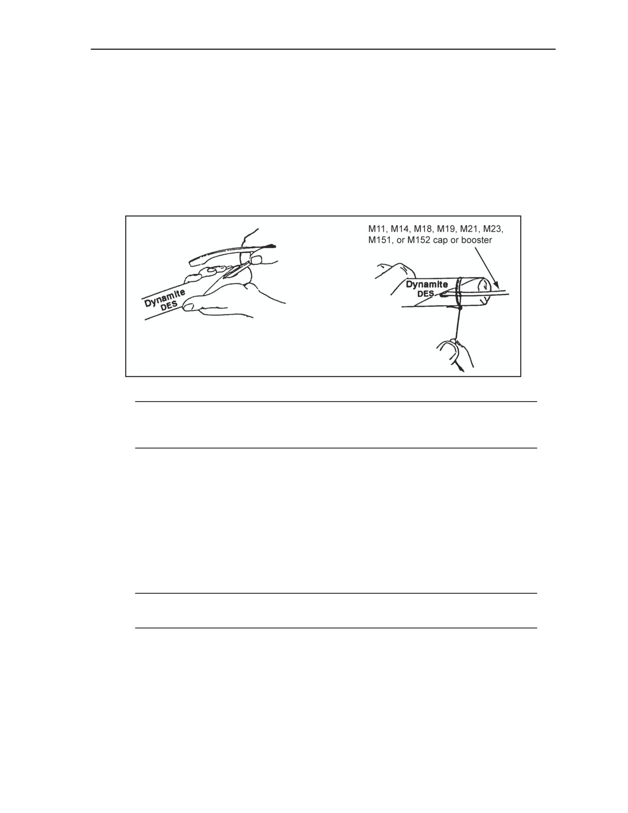
End-Priming Method
5-101. See Figure 5-20. The following steps and Figure 5-20 are used to perform end priming:
Step 1. Use M2 crimpers to make a cap well in the end of the dynamite cartridge.
Step 2. Insert the M11, M14, M18, M19, M21, M23, M151, or M152 cap or booster into the cap
well.
Step 3. Tie the M11, M14, M18, M19, M21, M23, M151, or M152 cap or booster and fuse
securely in the cartridge with a string.
Figure 5-20. End-Priming M1 Military Dynamite Using a DES
5-32
FM 3-34.214
11 July 2007
Demolition Operations and Training
Side-Priming Method
5-102. See Figure 5-21. The following steps and Figure 5-21 are used to perform side priming:
Step 1. Use M2 crimpers and make a cap well (about 1 1/2 inches long) in the side of the DES
cartridge at one end. Slightly slant the cap well so the M11, M14, M18, M19, M21, M23, M151,
or M152 cap or booster, when inserted, will be nearly parallel to the side of the DES cartridge
and the explosive end of the cap will be at a point nearest the middle of the cartridge.
Step 2. Insert a M11, M14, M18, M19, M21, M23, M151, or M152 cap or booster into the cap
well.
Step 3. Tie a string securely around the fuse. Wrap the string tightly around the cartridge,
making two or three turns before tying it.
Figure 5-21. Side-Priming M1 Military Dynamite DES
Note. Weatherproof the primed cartridge by wrapping a string closely around the cartridge,
extending it an inch or so on each side of the hole to cover the hole completely. Cover the string
with a weatherproof sealing compound.
DEMOLITION EFFECTS SIMULATORS WITH INTERNAL
DETONATING CORD BOOSTERS
5-103. These explosive DESs have an internal Uli or double-overhand knot with 18 inches of detonating
cord extending out (running end). This running end is used to prime the DES using detonating cord or an
M11, M14, M18, M19, M21, M23, M151, or M152 cap or booster. The two methods used are the—
Detonating cord method. Tape the detonating cord to the running end of the internal detonating
cord.
Nonelectric or electric method. Tape an M11, M14, M18, M19, M21, M23, M151, or M152
cap or booster to the running end of the internal detonating cord.
Note. This device also has an internal propellant (detonating cord) to expel the chalk powder and
sand mixture.
5-104. The paragraphs below contain priming instructions for the following:
A 1-pound, TNT block DES.
An M5A1 demolition block DES.
An M183 demolition satchel charge DES.
An M2A3 15-pound, shaped charge DES.
An M3 40-pound, shaped charge DES.
A 40-pound, cratering-charge DES.
11 July 2007
FM 3-34.214
5-33
Chapter 5
A bangalore torpedo DES.
1-POUND, TRINITROTOLUENE BLOCK DEMOLITION EFFECTS SIMULATOR
5-105. The paragraphs below contain priming instructions for the 1-pound TNT block DES. Discussed is
the use of detonating cord and MDIs.
Detonating Cord
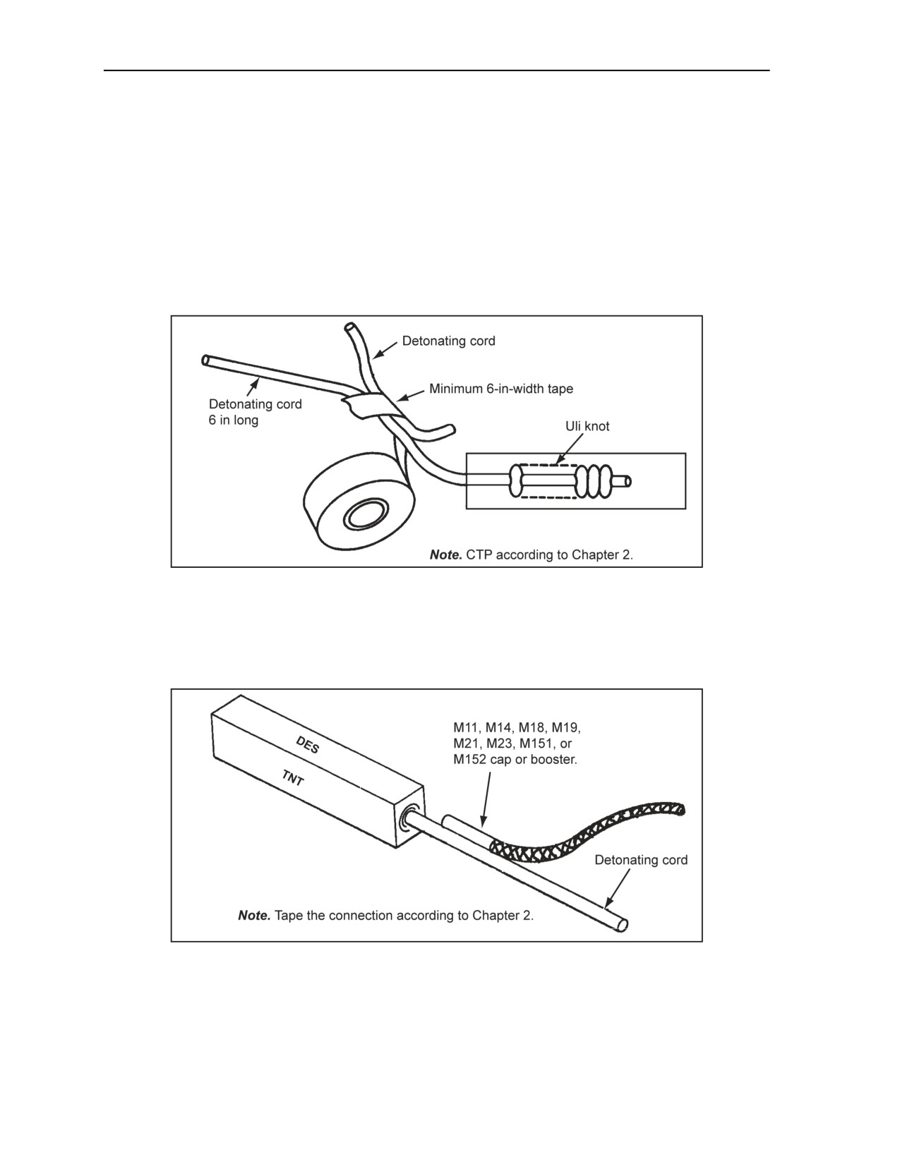
5-106. The method shown in Figure 5-22 is used for 1-pound TNT DES. Also, one of the three methods
for TNT without an internal detonating cord booster can be used, except the 18-inch tail is placed under the
wraps of the detonating cord.
Figure 5-22. Priming a TNT DES (With Booster) Using Detonating Cord
Modernized Demolition Initiator
5-107. As shown in Figure 5-23, tape an M11, M14, M18, M19, M21, M23, M151, or M152 cap or
booster to the detonating cord.
Figure 5-23. Priming a TNT DES (With Booster) With an MDI
M5A1 DEMOLITION BLOCK DEMOLITION EFFECTS SIMULATOR
5-108. The paragraphs below contain priming instructions for the M5A1 demolition block DES.
Discussed is the use of detonating cord and MDIs.
5-34
FM 3-34.214
11 July 2007
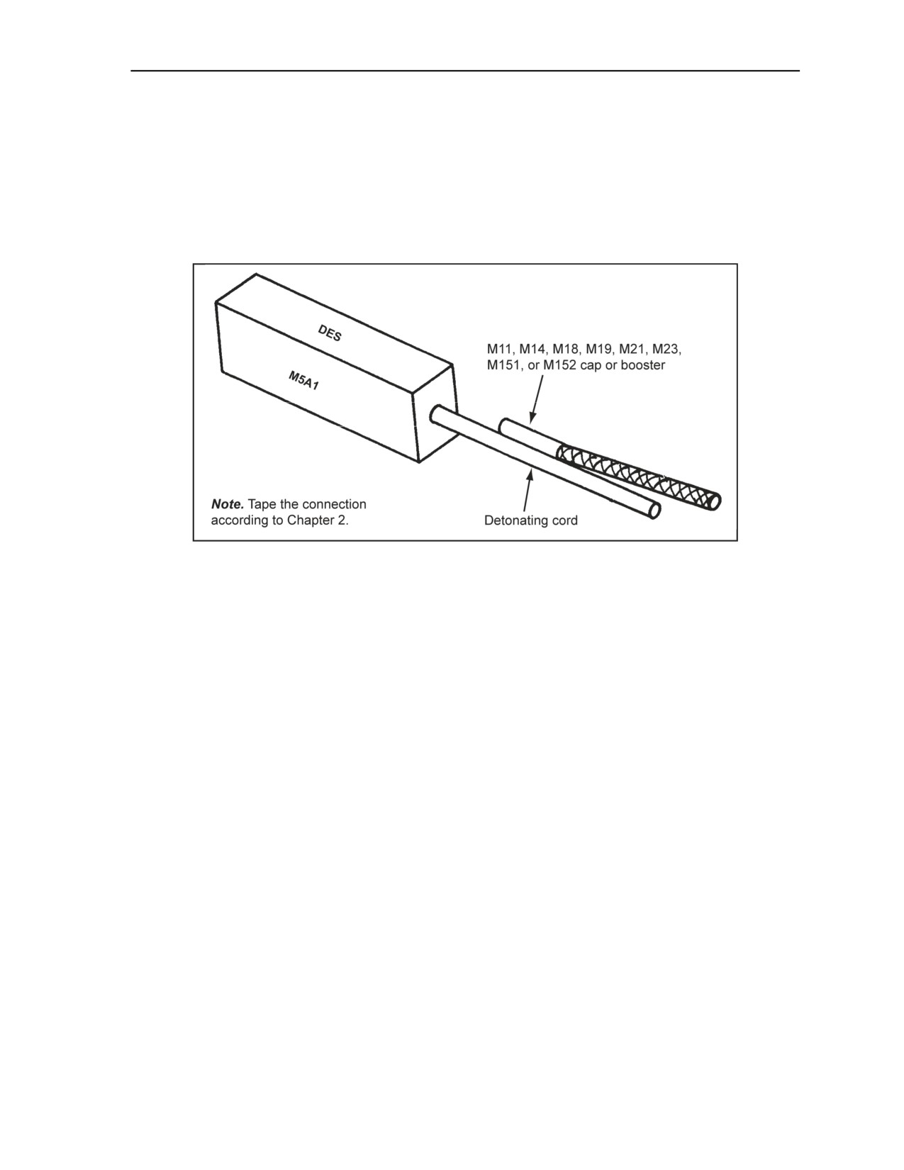
Demolition Operations and Training
Detonating Cord
5-109. See Figure 5-24 for priming the block. This is the same as TNT priming (paragraphs 2-23 through
2-28).
Modernized Demolition Initiator
5-110. See Figure 5-24. As shown in Figure 5-24, tape an M11, M14, M18, M19, M21, M23, M151, or
M152 cap or booster to the detonating cord.
Figure 5-24. Priming an M5A1 DES Using an MDI
M183 DEMOLITION SATCHEL CHARGE DEMOLITION EFFECTS SIMULATOR
5-111. The paragraphs below contain priming instructions for the M183 demolition satchel charge DES.
Discussed is the use of detonating cord and MDIs.
Detonating Cord
5-112. See Figure 5-25, page 5-36. Figure 5-25 shows how to prime the M183 demolition (or satchel
charge) assembly with detonating cord.
11 July 2007
FM 3-34.214
5-35
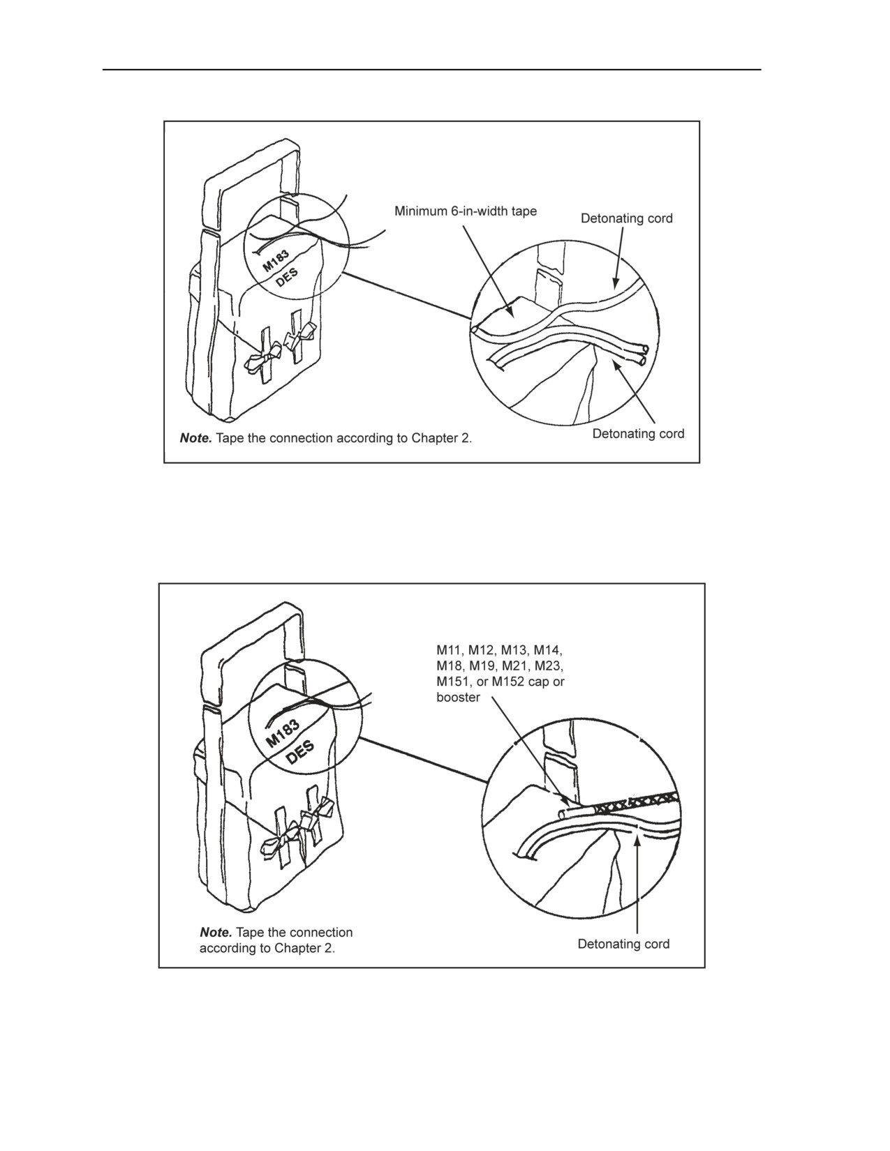
Chapter 5
Figure 5-25. Priming an M183 DES Using Detonating Cord
Modernized Demolition Initiator
5-113. See Figure 5-26. As shown in Figure 5-26, tape an M11, M12, M13, M14, M18, M19, M21, M23,
M151, or M152 cap or booster to the detonating cord.
Figure 5-26. Priming an M183 DES Using an MDI
5-36
FM 3-34.214
11 July 2007
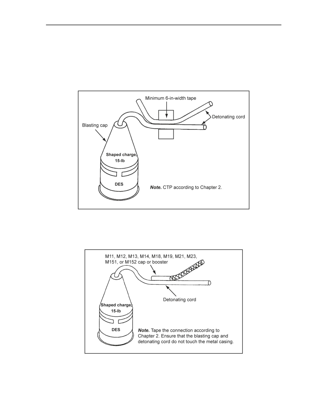
Demolition Operations and Training
M2A3 15-POUND, SHAPED CHARGE DEMOLITION EFFECTS SIMULATOR
5-114. The paragraphs below contain priming instructions for the M2A3 15-pound, shaped charge DES.
Discussed is the use of detonating cord and MDIs.
Detonating Cord
5-115. See Figure 5-27. Figure 5-27 shows how to prime an M2A3 15-pound, shaped charge DES using
detonating cord.
Figure 5-27. Priming a 15-Pound, Shaped Charge DES Using Detonating Cord
Modernized Demolition Initiator
5-116. See Figure 5-28. Figure 5-28 shows an M11, M12, M13, M14, M18, M19, M21, M23, M151, or
M152 cap or booster.
Figure 5-28. Priming a 15-Pound, Shaped Charge DES Using an MDI
11 July 2007
FM 3-34.214
5-37
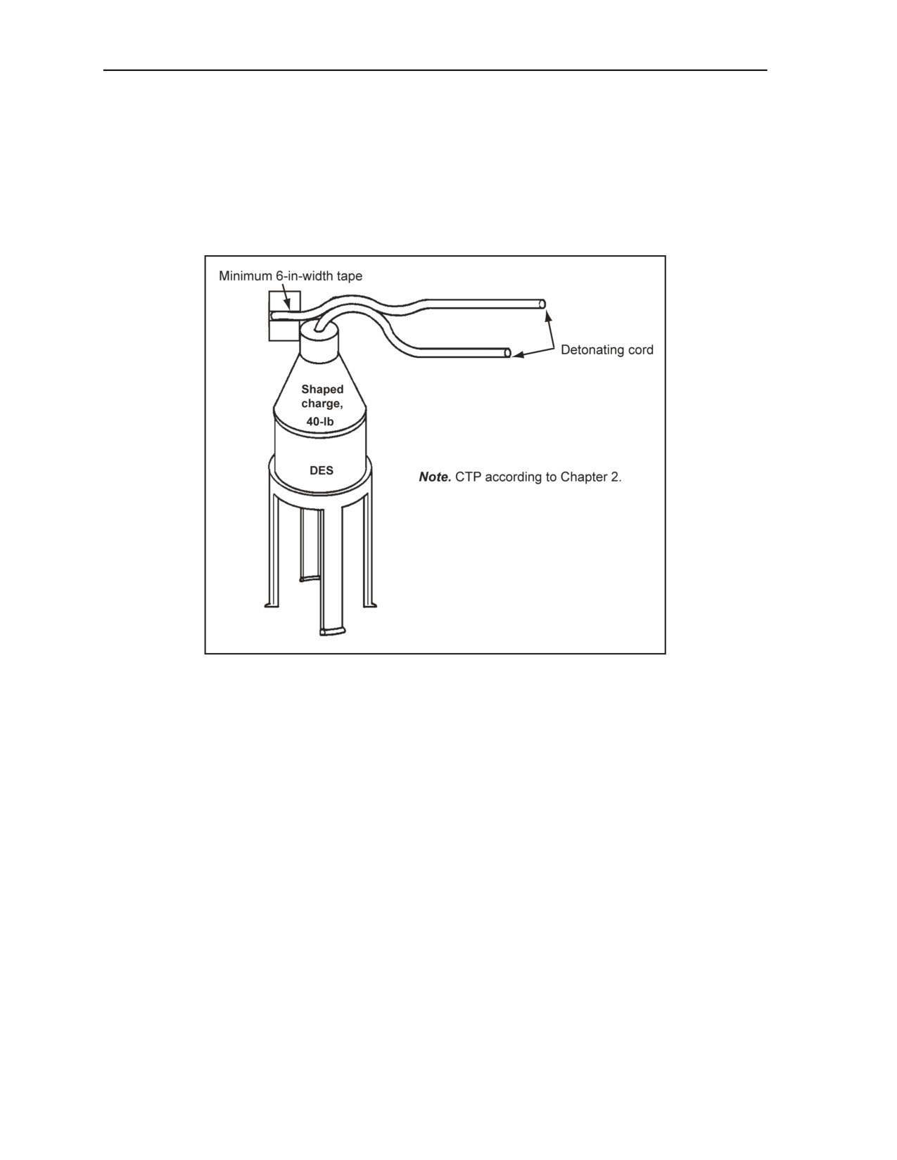
Chapter 5
M3 40-POUND, SHAPED CHARGE DEMOLITION EFFECTS SIMULATOR
5-117. The paragraphs below contain priming instructions for the M3 40-pound, shaped charge DES.
Discussed is the use of detonating cord and MDIs.
Detonating Cord
5-118. See Figure 5-29. Figure
5-29 shows how to prime a 40-pound, shaped charge DES using
detonating cord.
Figure 5-29. Priming a 40-Pound, Shaped Charge DES Using Detonating Cord
Modernized Demolition Initiator
5-119. See Figure 5-30. As shown in Figure 5-30, tape an M11, M12, M13, M14, M18, M19, M21, M23,
M151, or M152 cap or booster to the detonating cord.
5-38
FM 3-34.214
11 July 2007
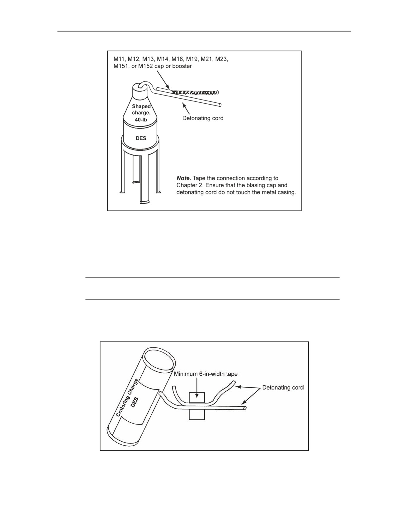
Demolition Operations and Training
Figure 5-30. Priming a 40-Pound, Shaped Charge DES Using an MDI
40-POUND, CRATERING-CHARGE DEMOLITION EFFECTS SIMULATOR
5-120. Aboveground, tape detonating cord or an M11, M12, M13, M14, M18, M19, M21, M23, M151, or
M152 cap or booster directly to the internal detonating cord booster that is sticking out of the DES charge.
Belowground, tape the detonating cord to the internally charged detonating cord branchline with a
minimum of 6-inch-width tape. Discussed is the use of detonating cord and MDIs.
Note. Do not use caps belowground. All belowground charges must be dual-primed with a
minimum of 1 pound of explosive.
Detonating Cord
5-121. See Figure 5-31. Figure 5-31 shows how to prime a 40-pound, cratering charge DES using
detonating cord.
Figure 5-31. Priming a 40-Pound, Cratering Charge DES Using Detonating Cord
11 July 2007
FM 3-34.214
5-39
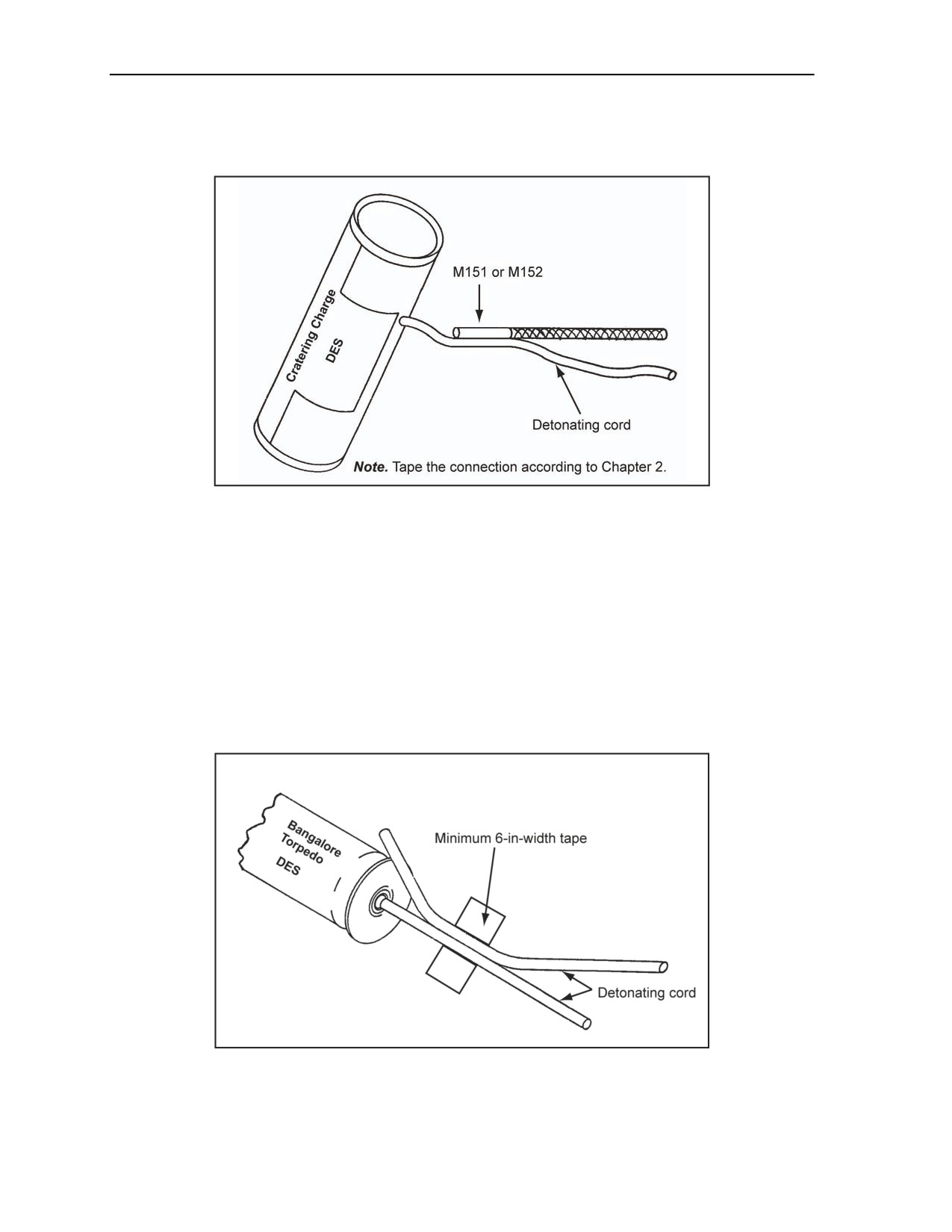
Chapter 5
Modernized Demolition Initiators
5-122. See Figure 5-32. As shown in Figure 5-32, tape an M151 or M152 cap to the detonating cord.
Figure 5-32. Priming a 40-Pound, Cratering Charge DES Using an MDI
BANGALORE TORPEDO DEMOLITION EFFECTS SIMULATOR
5-123. Priming instructions for the bangalore torpedo DES are discussed below. Discussed is the use of
detonating cord and MDIs.
Detonating Cord
5-124. A bangalore torpedo is primed using detonating cord as shown in Figure 5-33, page 5-40, or by
tying a square knot in place of the tape. When using a square knot, allow 6-inch tails to prevent misfires
from moisture contamination. Never use the short end (tail) of the detonating cord to initiate the torpedo.
Initiation must come from the running end of the detonating cord. Square knots may be placed in water or
in the ground, but the cord must be detonated from a dry end or aboveground.
Figure 5-33. Priming a Bangalore Torpedo DES Using Detonating Cord
5-40
FM 3-34.214
11 July 2007
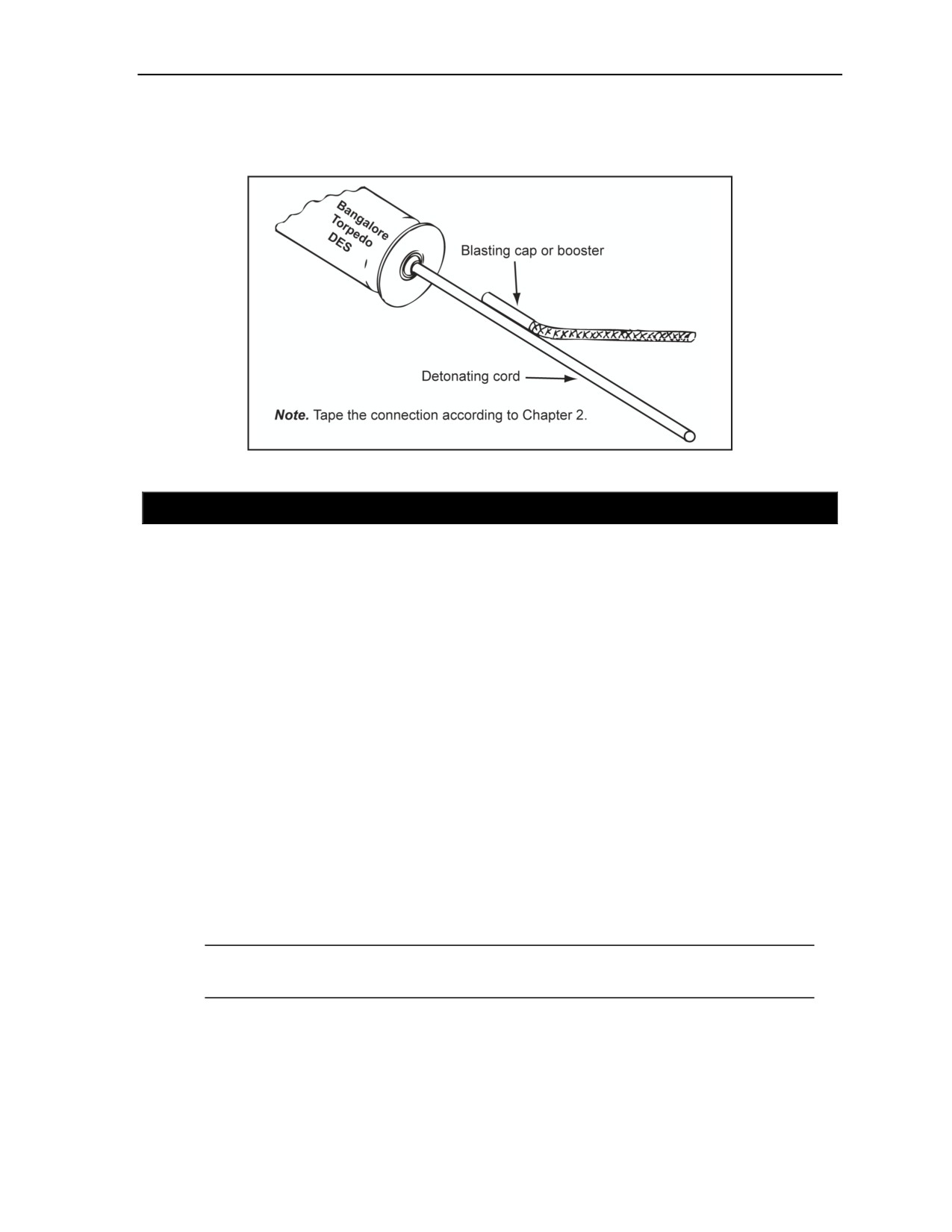
Demolition Operations and Training
Modernized Demolition Initiator
5-125. A blasting cap or booster is taped to the detonating cord booster. See Figure 5-34.
Figure 5-34. Priming a Bangalore Torpedo DES Using an MDI
SECTION V - SAFETY PROCEDURES AND RISK ASSESSMENT
5-126. Safety is not just a peacetime requirement. It is an integral part of the planning, preparation, and
execution phases of every mission, both for training and during combat. In war, as in peace, unsafe acts are
unacceptable. This section outlines and reviews safety procedures already in existence for the use of
demolitions and explosives. (See the safety procedures in Chapter 6 for additional information.)
SAFETY GUIDELINES
5-127. Unit leaders should continually make safety a primary emphasis during all phases of mission
planning and training whether inert, DES, or live explosives are in use. Leaders must continually review
safety references and teach safety procedures to each Soldier. Before using DESs, units must perform a risk
assessment. (See Appendix K for the safety risk assessment.)
LEADER RESPONSIBILITIES
5-128. Leaders must be aware of the need to address safety during all phases of an operation. Unit leaders
must constantly remind junior leaders and Soldiers about safety, and note deficiencies throughout the
planning, preparation, and execution phases of a demolition mission. Leaders need to consider the
following points during planning, preparation, and execution phases of all demolition operations:
Do not divide responsibilities for preparing, placing, or firing charges. Ensure that one individual
is responsible for supervising all phases of the operation.
Prime and use explosive materials according to their intended purpose.
Ensure that MSDs are enforced and tactically or administratively cleared.
Note. At a minimum, leaders and Soldiers must maintain the MSD as prescribed in AR 385-63
and Table 6-2, page 6-7, of this FM.
Ensure that Soldiers handle and inspect all DESs and live munitions according to this FM.
Ensure that transportation and storage are according to the local demolitions standing operating
procedure (SOP). Ensure that units establish appropriate ammunition handling areas.
Ensure that no blasting caps or firing systems are attached to any detonating cord or other charge
(DES or live) unless a demolitions NCO is notified he and approves of it.
11 July 2007
FM 3-34.214
5-41

This page is intentionally left blank.

Chapter 6
Demolition Safety
This chapter deals with the safety surrounding demolitions. The main safety points
for the different types of demolitions and demolition devices are discussed. Also
outlined in this chapter are the misfire procedures, transportation and storage safety,
military explosives destruction, and environmental protection.
SECTION I - GENERAL SAFETY
CONSIDERATIONS
6-1. When dealing with demolitions, general safety should be observed. The following should be
considered when dealing with the general safety of demolitions:
Do not attempt to conduct a demolitions mission if you are unsure of the demolition procedures;
review references or obtain assistance.
Prevent inexperienced personnel from handling explosives.
Avoid dividing responsibility for demolition operations.
Use the minimum number of personnel necessary to accomplish the demolition mission.
Take your time when working with explosives; make your actions deliberate.
Post guards at all times to prevent access inside the danger radius.
Maintain control of the blasting machine or initiation source at all times.
Use the minimum amount of explosives necessary to accomplish the mission while keeping
enough explosives in reserve to handle any possible misfires.
Maintain accurate accountability of all explosives and accessories.
Store blasting caps separately and at a safe distance from other explosives.
Ensure that all personnel and equipment are accounted for before detonating a charge.
Ensure that warnings are given before initiating demolitions; give the warning “Fire in the hole!”
three times.
Guard the firing points at all times.
Assign a competent safety officer for every demolition mission.
Dual initiate all demolitions, regardless of whether they are single- or dual-primed.
Avoid using deteriorated or damaged explosives.
Do not dismantle or alter the contents of any explosive material.
Do not mix live and inert (dummy) explosives.
Do not use blasting caps underground. Use detonating cord or M151 or M152 boosters to prime
underground charges. See FM 3-34.465 for quarry operations.
EXPLOSIVE MATERIALS
6-2. Explosive materials consist of blasting caps, time fuse, shock tubes, detonating cord, low-strength
detonating cord, plastic and sheet explosives, FPE binary explosive charges, and commercial explosives.
Boosters consists of M151s and M152s (see Chapter 2). The paragraphs below describe how each of these
materials are used.
11 July 2007
FM 3-34.214
6-1

Chapter 6
BLASTING CAPS
6-3. Both military and commercial blasting caps are extremely sensitive and can explode unless handled
carefully. Blasting caps can detonate if exposed to extreme heat (cook off). Military blasting caps are more
powerful and often more sensitive than their commercial counterparts. When using commercial blasting
caps to detonate military explosives, ensure that they are powerful enough to detonate the explosives, thus
avoiding misfires.
WARNING
Power requirements for electric caps from different
manufacturers vary, so never mix caps from different
manufacturers or lots because this could result in misfires.
Failure to comply could result in immediate personal injury or
damage to equipment.
6-4. When installing caps in explosives, never force them into an explosive or a cap well; the appropriate
tool for making or enlarging the cap well should be used. When taping the blasting cap onto the detonating
cord, ensure that 1/8 to 1/4 inch of the cap is clearly visible at both ends. When nonessential personnel are
on site, do not connect blasting cap initiating sets to ring or line mains or charges. Blasting caps should
never be left unattended before or after attaching them to the charges or firing system.
Nonelectric Blasting Caps
6-5. When using nonelectric blasting caps as an explosive material, the following procedures are used:
Use only authorized equipment and procedures when crimping nonelectric blasting caps to the
time fuse or detonating cord.
Maintain blasting caps in the appropriate cap box until needed. Never store blasting caps with
explosives.
Do not carry loose blasting caps in pockets or place them in containers. Ensure that they are
secured.
Do not blow into a nonelectric cap or attempt to remove any obstructions from the blasting cap
well. Remove obstructions that will dislodge by using the wrist-to-wrist tap method.
Do not insert anything but time fuse or detonating cord into a nonelectric blasting cap. Do not
twist the time fuse or detonating cord while attempting to insert it into a blasting cap.
Do not attempt to crimp a blasting cap that is installed in an explosive. Remove the blasting cap
from the charge if the blasting cap has come loose from the time fuse or detonating cord, recrimp
the cap, and then reinstall the cap in the charge.
Avoid striking, pinching, and mashing nonelectric blasting caps during crimping activities. Use
only M2 crimpers for all crimping operations.
Cut the fuse to allow an interval of not less than 10 seconds between firings when using
nonelectric blasting caps to dual-prime demolitions.
Electric Blasting Caps
6-6. When using electric blasting caps as an explosive material, the following procedures are applied:
Do not remove the short-circuiting shunt unless the cap is being tested or connected. (The shunt
prevents accidental initiation by static electricity.) Twist the bare ends of the lead wires together
at least three times (180° turns) to provide a proper shunt, if the blasting cap has no shunt.
Use proper grounding procedures when static electricity is present (see paragraph 6-19).
Protect the blasting caps by placing them in a metal can with a snug-fitting cover (1/2 inch or
more of cover overlap) when transporting electric blasting caps near vehicles (including aircraft)
equipped with a transmitter. Do not remove blasting caps from their containers near an operating
transmitter unless the hazard has been judged acceptable.
6-2
FM 3-34.214
11 July 2007

Demolition Safety
Keep electric blasting caps at least 155 meters from energized power lines. Temporarily cut the
power to the lines during blasting operations if using electric blasting caps near power lines.
Use at least the minimum current required to fire electric blasting caps.
Check circuit continuity of electric blasting caps before use.
Cover connections between blasting cap leads and firing wires with insulating tape, not the
cardboard spool.
Remove firing wire loops and, if practical, bury blasting wires.
WARNING
Never mix caps from different manufacturers because power
requirements for electric caps from different manufacturers vary
and could result in misfires. Failure to comply could result in
immediate personal injury or damage to equipment.
TIME FUSE
6-7. When using time fuse, the following procedures are used:
Conduct a test burn of at least 3 feet for each roll of time fuse. Perform another test burn before
using the fuse if the fuse has not been used within 24 hours of the test burn.
Use M2 crimpers to cut the time fuse. Use a sharp knife to cut the fuse if serviceable M2
crimpers are not available. Ensure that the fuse end is cut squarely. Make the cut on a
nonsparking surface, such as wood.
Note. A rough or jagged-cut fuse can cause a misfire.
Avoid cutting the fuse until it is ready to be inserted into the igniter and blasting cap.
Do not use the first or last 6 inches of the time fuse from a new or partial roll (this helps to avoid
problems from moisture infiltration).
Avoid sharp bends, loops, and kinks in the time fuse.
Avoid stepping on the fuse.
Note. Any of these conditions or actions can break the powder train and result in a misfire.)
SHOCK TUBES
6-8. The detonation is contained within the plastic tubing and if strands of tubing touch or cross over each
other there is no concern that an inadvertent ignition would occur. Fragments from blasting caps or other
explosive charges travel at speeds three to five times faster than the detonating wave in the shock tube.
These fragments could cause damage to other shock tube assemblies. The following procedures are applied:
Never use crimpers when cutting shock tubes.
Splice shock tubes only when the MDI components cannot be replaced.
6-9. The flash of the shock tube can produce a burn if a piece of shock tube is held when it is functioning,
even through the olive drab coating. Therefore, never hold a shock tube while detonating an explosive
system. If an unsealed shock tube is left unused for extended periods, it may not be reliable and should not
be used.
DETONATING CORD
6-10. Detonating cord should not be carried or held around your neck. The additional 6-inch tail should not
be cut off when cutting detonating cord because 6-inch tails are standard on the knots to avoid moisture
infiltration. Sharp bends, loops, and kinks should be avoided, and the cord should not be stepped on. Any of
11 July 2007
FM 3-34.214
6-3

Chapter 6
these conditions or actions can change the path of detonation or cause the cord to cut itself. When using
detonating cord, the following procedures are used:
Use M2 crimpers to cut the time fuse. Use a sharp knife to cut the fuse if serviceable M2
crimpers are not available. Ensure that the fuse end is cut squarely. Make the cut on a
nonsparking surface, such as wood.
Note. A rough or jagged-cut fuse can cause a misfire.
Avoid cutting the fuse until it is ready to be inserted into the blasting cap.
Do not use the first or last 6 inches of the time fuse from a new or partial roll (this helps to avoid
problems from moisture infiltration).
LOW-STRENGTH DETONATING CORD
6-11. Low-strength detonating cord is precrimped to a booster in all military applications and should be
handled carefully. When installing boosters in explosive, never force them into an explosive or a cap well;
the appropriate tool should be used for making or enlarging the cap well. The following procedures are
used:
Never leave boosters unattended before or after attaching them to explosive charges.
Do not carry or hold low-strength detonating cord around your neck.
Do not cut an additional 6-inch tail off when cutting low-strength detonating cord, because 6
inch tails are standard for taping and on knots to avoid moisture infiltration.
Avoid sharp bends, loops, crossovers, and kinks in the detonating cord.
Avoid stepping on it the cord.
Note. Any of these conditions or actions can change the path of detonation or cause the cord to
cut itself.
PLASTIC AND SHEET EXPLOSIVES
6-12. Plastic and sheet explosives should be cut with a sharp knife on a nonsparking surface; never use
shears. Handling of explosives with your bare skin should be avoided as much as possible.
FIGHTING POSITION EXCAVATOR BINARY EXPLOSIVE CHARGES
6-13. The following procedures are used when dealing with FPE binary explosive charges:
Do not mix the nonexplosive binary components together until you are ready to emplace the
charges. Do not attempt to separate the containers after mixing.
Note. Once the contents of the binary components are mixed, they form an explosive, and the
process cannot be undone.
Hold the liquid container with the seal facing up, and screw the powder container onto the liquid
container to avoid spilling the contents when screwing the two nonexplosive containers together.
Ensure that the binary charges are preprimed with a booster attached to low-strength detonating
cord.
Avoid sharp bends, loops, crossovers, and kinks in the branchlines.
Avoid stepping on the cord.
Note. Any of these conditions or actions can change the path of low-strength detonating cord or
cause the cord to cut itself.
6-4
FM 3-34.214
11 July 2007

Demolition Safety
Do not twist or pinch the cord when using the branchline to lower the explosive charges into
bore holes.
Do not use excessive force to pull out the charges if the charges need to be readjusted in the
borehole.
COMMERCIAL EXPLOSIVES
6-14. Commercial dynamite is sensitive to heat, shock, and friction and is not recommended for use in
combat areas. Old commercial dynamite should not be used, because it is extremely sensitive and very
unstable. The procedures in DA Pamphlet 385-64, the Army publications used, or the manufacturer’s
recommendations should be followed to destroy aged commercial dynamite. When commercial dynamite
freezes, it becomes covered with crystals and is very unstable (do not use frozen dynamite).
Note. Commercial dynamite containing nitroglycerin requires special handling and storage.
When in storage, commercial dynamite should be rotated to prevent the nitroglycerin from
settling to the bottom of the explosive.
BOREHOLES
6-15. No void spaces should be left in boreholes, especially in quarrying operations. A secondary
explosion can result from a borehole with voids between loaded explosives. After the first blast, it may take
up to 15 minutes for such an explosion to occur. All voids should be tamped with the appropriate material.
When using detonating cord wick to dig boreholes, allow at least 30 minutes for boreholes to cool between
placing and firing successive detonating cord wick, or cool the boreholes with water or compressed air to
save time.
TOXICITY
6-16. Enough time should be allowed for blast fumes, dust, and mist to clear before inspecting or
occupying a blasting area. Most military explosives are poisonous if ingested and will produce lethal gases
if detonated in confined areas (such as tunnels, caves, bunkers, and buildings). TNT is extremely poisonous
and it should be avoided when blasting in enclosed areas.
WARNING
When working with explosives, avoid touching sensitive areas of
your body, such as around the face and groin. After working with
explosives, wash your hands, especially before consuming food.
Failure to comply could result in immediate personal injury or
damage to equipment.
NATURAL PHYSICAL PROPERTIES
6-17. Natural physical properties include lightning, static electricity, induced currents, blast effects, and
missile hazards. Each of these are discussed in the paragraphs below.
LIGHTNING
6-18. Lightning is a hazard to both electric and nonelectric blasting charges. A lightning strike or a nearby
miss is almost certain to initiate either system type. If lightning strikes occur, even far away from the
blasting site, electrical firing circuits could be initiated by high, local earth currents and shock waves
resulting from the strikes. These effects are increased when lightning strikes occur near conducting
elements, such as fences, railroads, bridges, streams, and underground cables or conduits and in or near
11 July 2007
FM 3-34.214
6-5

Chapter 6
buildings. The only safe procedure is to suspend all blasting activities during electrical storms or when an
electrical storm is imminent.
STATIC ELECTRICITY
6-19. Though rare, electric blasting caps can possibly be initiated by static electricity. If possible, avoid
using electric blasting caps if static electricity is a problem. Exercise extreme caution when working with
explosives in cold, dry climates or when wearing clothing and equipment that produce static electricity,
such as clothing made of nylon or wool. Before handling an electric blasting cap, always remove the static
electricity from your body by touching the earth or a grounded object. It may be necessary to perform this
grounding procedure often in an area where static electricity is a constant problem.
INDUCED CURRENTS
6-20. Radio signals can induce a current in electric blasting caps and prematurely detonate them. Table 6-1
lists the MSDs from transmitters for safe electrical blasting. This table applies to operating radio, radar,
microwave, cellular telephone, and television transmitting equipment near electric caps. Keep mobile
transmitters and portable transmitters at least 50 meters from any electric blasting cap or electrical firing
system. Electric blasting caps should not be used within 155 meters of energized power transmission lines.
Table 6-1. MSD for Blasting Near Radio Frequency Energy
Average or Peak Transmitter Power* (in watts)
MSD (in meters)
0 to 29
30
30 to 49
50
50 to 99
110
100 to 249
160
250 to 499
230
500 to 999
305
1,000 to 2,999
480
3,000 to 4,999
610
5,000 to 19,999
915
20,000 to 49,999
1,530
50,000 to 100,000
3,050
*When the transmission is a pulsed- or continuous-wave type and its pulse widths are less than 10 microseconds, the
left-hand column indicates the average power. For all other transmitters, including those with pulse widths greater
than 10 microseconds, the left-hand column indicates peak power.
BLAST EFFECTS
6-21. A blast effect is the destruction of or damage to structures and personnel by the force of an explosion
on or above the surface of the ground. Blast effect may be contrasted with the cratering and ground-shock
effects of a projectile or charge that goes off beneath the surface. (JP 1-02) (FM 1-02)
6-22. Personnel close to explosions may experience permanent hearing loss or other injury from the
pressure wave caused by an explosion. Hearing protection should be worn during all blasting operations.
Personnel observing MSDs for bare charges (Table 6-2 and AR 385-63) generally will not be affected by
blast effects. See AR 385-63 and DA Pamphlet 385-63 for additional information on blast effects.
Note. See Chapter 7 for explosive urban entry techniques.
6-6
FM 3-34.214
11 July 2007
Demolition Safety
Table 6-2. MSD for Personnel in the Open (Near Bare Charges)
Explosive
MSD
Explosive
MSD
Weight (lb)
Weight (lb)
Feet
Meters
Feet
Meters
27 or less
985
300
175
1,838
560
30
1,021
311
200
1,920
585
35
1,073
327
225
1,999
609
40
1,123
342
250
2,067
630
45
1,168
356
275
2,136
651
50
1,211
369
300
2,199
670
60
1,287
392
325
2,258
688
70
1,355
413
350
2,313
705
80
1,415
431
375
2,369
722
90
1,474
449
400
2,418
737
100
1,526
465
425
2,461
750
125
1,641
500
500
2,625
800
150
1,752
534
—
—
—
MISSILE HAZARDS
6-23. Explosives can propel lethal missiles great distances. The distances these missiles will travel in the
air depends primarily on the relationship between the missiles weight, shape, density, initial projection
angle, and initial speed. Under normal conditions, the missile-hazard area of steel-cutting charges is greater
than that of cratering, quarrying, and surface charges.
UNDERWATER OPERATIONS
6-24. Underwater operations include the use of explosives, nonelectric caps, time fuse, detonating cord,
MDI components, and M60 or M81 fuse igniters. Each of these is discussed in detail in the paragraphs that
follow.
EXPLOSIVES
6-25. Explosives are subject to erosion by water. Unprotected explosives will deteriorate rapidly, reducing
their effectiveness. All exposed explosives should be adequately protected when used in water, especially
running water.
NONELECTRIC CAPS
6-26. Nonelectric caps depend on combustion to work properly. Any moisture inside a nonelectric cap may
cause a misfire. Because nonelectric blasting caps are difficult to waterproof, explosives should be primed
with detonating cord. The M151 or M152 boosters and detonating cord can be used to prime demolition
charges underwater.
TIME FUSE
6-27. Time fuse depends on combustion to burn properly. Time fuse burns significantly faster underwater
due to water pressure. The fuse is placed underwater at the last possible moment before firing.
Note. If the mission requires using time fuse underwater, then do the testburn underwater.
11 July 2007
FM 3-34.214
6-7

Chapter 6
DETONATING CORD
6-28. The ends of detonating cord are sealed with a waterproof sealing compound when using detonating
cord for initiating underwater charges or charges that will remain in place several hours before firing.
Leaving a 6-inch overhang in the detonating cord will protect the remaining line from moisture.
MODERNIZED DEMOLITION INITIATOR COMPONENTS
6-29. All MDI components (except for the M81) are factory-crimped to a blasting cap or booster and
sealed for waterproofing to 70 feet (5 feet for the M14 and M18). MDI components should be inspected to
ensure that there are no punctures in the shock tube, low-strength detonating cord, and time fuse and that all
crimps and seals are intact before emplacing them underwater. The M151 or M152 boosters and detonating
cord can be used to prime demolition charges underwater. When cutting shock tube or time fuse to attach
an M81 igniter, do not allow moisture to enter the open end.
M60 OR M81 FUSE IGNITERS
6-30. The M60 or M81 should not be used underwater. Water can penetrate the fuse igniter through the
vent hole located in the pull rod.
SAFE DISTANCES
6-31. The following general rules apply when determining the distances at which personnel in the open are
relatively safe from missiles created by bare charges placed on the ground, regardless of the type or
condition of the soil (AR 385-63). Table 6-2, page 6-7, lists the MSDs for selected charge weights.
Charges of less than 27 pounds. The minimum missile-hazard distance is 300 meters.
Charges of more than 27 pounds, but less than 425 pounds. The distances in Table 6-2
should be used.
Charges of more than 425 pounds. The MSD is 750 meters.
Charges of more than 2,000 pounds. The following formulas should be used:
MSD (meters) = 100 3
pounds of explosive
3
MSD (feet) = 300
pounds of explosive
Note. See Chapter 7 for explosive urban entry techniques.
6-32. Missile-proof shelters can be as close as 100 meters from the detonation site, provided they are
strong enough to withstand the heaviest possible missile resulting from the demolition. All personnel will
wear approved protective helmets and single hearing protection.
SECTION II - MISFIRE PROCEDURES
CHARGES FIXED TO TARGETS
6-33. When charges are fixed to targets and not simply placed on the ground, the following MSDs are
used:
Charges placed on steel.
The preferred method of employing steel-cutting charges is in a bunker designed for that
purpose. Steel-cutting charges (amount of explosives and placement) will be calculated
based on the appropriate formulas and the tables in this FM.
6-8
FM 3-34.214
11 July 2007

Demolition Safety
If a steel-cutting bunker is not available, charges will be fired in an excavated pit that is at
least
1 meter deep, and a mat made of a hemp-type material must cover the charge.
Steel-cutting charges fired outside a steel-cutting bunker will not exceed 0.9 kilogram.
Personnel must be a minimum of 100 meters from the charge at detonation and must be in a
missile proof shelter, 300 meters in defilade, or 1,000 meters if in the open.
Charges placed on concrete.
Charges placed on concrete will not exceed 18 kilograms and should be placed on the side
nearest the observers.
Observers must be at least 100 meters away in a missile-proof shelter, 300 meters away in
defilade, or 900 meters away in the open. An unoccupied distance of 900 meters will be
provided on the opposite side of the charge where most missile hazards will be thrown.
BANGALORE TORPEDO
6-34. Personnel must be a minimum of 100 meters from the charge at detonation. Personnel must be in a
missile-proof shelter, 300 meters if in a defilade, or 1,000 meters if in the open.
SLAM M4
6-35. Personnel must be a minimum of 100 meters from the charge at detonation. Personnel must be in a
missile-proof shelter, 300 meters if in a defilade, or 1,000 meters if in the open.
NONELECTRIC
6-36. Nonelectric misfires may be caused by—
Moisture in the time fuse, detonating cord, or explosives.
Failure to seat the time fuse completely in the blasting cap or the fuse igniter.
Failure to seat the shock tube or time fuse completely in the fuse igniter.
Breaks in the time fuse, shock tube, or detonating cord.
Time fuse having jagged or uneven ends.
Failure to seat the blasting caps securely in the cap well or explosive.
Loosely or improperly installed detonating cord.
Debris in the blasting cap.
Blasting caps from commercial sources that are not strong enough to detonate military
explosives.
PREVENTION
6-37. Nonelectric misfires are minimized by taking the following precautions:
Prepare and place all primers properly.
Load all charges carefully.
Detonate charges with the proper techniques.
Use dual-initiation systems and, if possible, dual-firing systems.
Use detonating cord or M151 or M152 for underground demolitions. Do not bury the blasting
caps.
Perform tamping operations carefully to avoid damaging prepared charges.
Avoid crimping blasting caps onto time fuse in the rain; seek a covered area out of the rain.
Ensure that the time fuse or shock tube is completely seated when installing it into a blasting cap
or fuse igniter.
11 July 2007
FM 3-34.214
6-9

Chapter 6
CLEARING PROCEDURE
6-38. The Soldier who placed the charges should investigate any misfires, and correct any problems with
the demolition using the following procedures:
Note. During training, the range safety officer
(RSO) or officer in charge
(OIC) should
investigate any misfires and correct any problems with the demolitions.
After attempting to fire the demolition, delay investigating any detonation problem for at least
30 minutes, plus the time remaining on the secondary initiating system. Sometimes, tactical
conditions may require an investigation before the 30-minute limit.
Note. For Navy and Marine Corps, wait 60 minutes plus the time remaining on the secondary
initiating system (see NAVSEA SW060-AA-MMA-010).
For aboveground misfires of charges primed with blasting caps, place a primed, 1-pound charge
next to the misfired charge, and detonate the new charge. Each misfired charge or charge
separated from the firing circuit that contains a blasting cap requires a 1-pound charge for
detonation. Scattered charges that contain blasting caps should not be touched; they must be
destroyed in place. For charges primed with detonating cord, follow the procedures in
paragraphs 6-42 through 6-45.
For a nonelectric cap that has detonated but failed to initiate a detonating cord branchline, line
main, or ring main, attach a new cap to the detonating cord, and then move to a safe place.
For buried charges, remove the tamping to within 1 foot of the misfired charge and constantly
check the depth while digging to avoid striking the charge. When you are within 1 foot of the
misfired charge, place a primed, 2-pound charge on top of the original charge, and detonate the
new charge. If digging over the original charge is impractical, dig a new borehole of the same
depth beside the original hole, 1 foot away, and then place a primed, 2-pound charge in the new
hole and detonate the new charge.
ELECTRIC
6-39. Electric misfires may be caused by—
An inoperable or weak blasting machine or power source.
Improper operation of the blasting machine or power source.
Defective or damaged connections (such as short circuits, breaks in the circuit, or too much
resistance in the electrical wiring) are common conditions resulting in misfires.
Faulty blasting caps.
Different manufacturers’ blasting caps being used in the same circuit.
An inadequate power source for the number of blasting caps in the circuit (such as too many
caps or too small a blasting machine).
PREVENTION
6-40. One Soldier should be assigned the responsibility for all the electrical wiring in a demolition circuit.
This Soldier should—
Perform all splicing.
Install all blasting caps in the firing circuit, and not bury the blasting caps.
Make all of the connections between blasting cap wires, connecting wires, and firing wires.
Inspect the system for short circuits.
Avoid grounding out the system.
Ensure that the number of blasting caps in any circuit does not exceed the rated capacity of the
power source.
6-10
FM 3-34.214
11 July 2007

Demolition Safety
CLEARING PROCEDURE
6-41. The following procedures are used to clear electric misfires:
Make another attempt to fire.
Use the secondary firing system, when present.
Check the wire connections, blasting machine, or power-source terminals.
Disconnect the blasting machine or power source, and test the blasting circuit. Check the
continuity of the firing wire with a circuit tester.
Use another blasting machine or power source and attempt to fire the demolition again, or
change operators.
Disconnect the blasting machine, shunt the wires, and investigate immediately when employing
only one electrical-initiation system. When employing more than one electrical-initiation system,
wait 30 minutes before inspecting. (Tactical conditions may require an investigation before the
30-minute limit.)
Note. For Navy and Marine Corps, wait 60 minutes (see NAVSEA SW060-AA-MMA-010).
Inspect the entire circuit for wire breaks or short circuits.
Do not attempt to remove or handle an electric blasting cap if a problem is suspected. Place a
primed, 1-pound charge next to the misfired charge, and detonate the new charge.
Note. When using a combination-initiated system, refer to paragraph 6-36 through 6-38for the
procedures for a nonelectric misfire.
DETONATING CORD
6-42. The paragraphs below should be used when dealing with detonating cord misfires. Discussed is how
to handled detonating cord, detonating cord priming, and M151 and M152 booster low-strength detonating
cord misfires.
DETONATING CORD
6-43. If the detonating cord fails to function properly, a new blasting cap should be attached to the
remaining detonating cord, taking care to fasten it properly, and detonate the new blasting cap. Branchlines
should be treated the same.
DETONATING CORD PRIMING
6-44. If the detonating cord leading to the charge detonates but fails to explode the charge, the following
action should be taken:
Do not investigate until the charges have stopped burning. Wait 30 minutes if the charge is
underground.
Reprime and attempt to detonate the charge. Collect scattered charges that do not contain
blasting caps, and detonate them together.
Dig near underground charges to within 1 foot of the charge. Place a primed, 2-pound charge on
top or to the side of the charge, and detonate the new charge.
M151 OR M152 BOOSTER LOW-STRENGTH DETONATING CORD
6-45. If the low-strength detonating cord leading to the charge functioned but failed to explode the charge,
take the following action:
Wait 30 minutes.
Follow the procedures for buried charges in paragraph 6-38.
11 July 2007
FM 3-34.214
6-11

Chapter 6
SECTION III - TRANSPORTATION AND STORAGE SAFETY
TRANSPORTATION
6-46. When transporting explosives, Soldiers should observe both military and commercial transportation
regulations and safety procedures. The paragraphs below discuss these regulations and procedures.
REGULATIONS
6-47. Both military and commercial carriers are subject to regulations when transporting military
explosives and other dangerous military materials within the United States. AR 385-64 and
DA Pamphlet 385-64 contain the minimum safety requirements for handling and transporting military
explosives and ammunition. When transporting explosives outside the United States, follow the regulations
from the host countries as well. All explosives transport personnel must learn the local procedures and
safety procedures.
SAFETY PROCEDURES
6-48. The commander should assign a primary and assistant operator to each vehicle transporting
explosives on public highways, roads, or streets. Whenever transporting explosives locally, operators must
observe safety rules.
Vehicles
6-49. When using vehicles to transport explosives, these precautions are followed:
Ensure that vehicles are in good condition. Inspect all vehicles intended for hauling explosives
before loading them. Protect against any short circuits in the electrical system.
Install fire-resistant and nonsparking cushioning to separate the explosives from any metal truck
components if using vehicles with steel or partial-steel bodies.
Do not load vehicles beyond their rated capacities when transporting explosives.
Cover open-bodied vehicles hauling explosives with a fire-resistant tarpaulin.
Mark all vehicles transporting explosives with reflective placards indicating the explosive types
carried (see AR 385-64 and DA Pamphlet 385-64).
Use demolition transports for explosives only. Do not carry metal tools, carbides, oils, matches,
firearms, electric storage batteries, flammable substances, acids, or oxidizing or corrosive
compounds in the bed or body of any vehicle transporting explosives.
Equip vehicles transporting explosives with not less than two Class 10 BC fire extinguishers for
on-post shipments. Place the extinguishers at strategic points so they are ready for immediate
use. Keep vehicles away from congested areas. Consider the parking congestion.
Operate vehicles transporting explosives with extreme care. Do not drive at a speed greater than
35 miles per hour. Make full stops at approaches to all railroad crossings and main highways.
Note. This does not apply to convoys or crossings protected by guards or highway workers
(flaggers).
Keep flames at least 50 feet from vehicles or storage points containing explosives.
Cargo (Explosives)
6-50. When transporting explosives, these precautions are followed:
Do not leave explosives unattended.
Do not mix live and inert (dummy) explosives.
Secure the load of explosives in the transport to prevent shifting during transport.
6-12
FM 3-34.214
11 July 2007

Demolition Safety
Do not transport blasting caps or other initiators in the same vehicles carrying explosives unless
absolutely necessary. Separate the blasting caps from other explosives if both blasting caps and
explosives must be carried in the same vehicle.
Note. Carry the caps in a closed metal container in the cab of the transport.
Do not allow anyone other than the primary and assistant operators to ride on or in a truck
transporting explosives. Do not refuel a vehicle while carrying explosives except in an
emergency.
Fire
6-51. If fire breaks out in a vehicle transporting explosives, these actions are followed:
Try to stop the vehicle away from any populated areas.
Stop traffic from both directions. Warn the vehicle drivers and passengers and occupants of
nearby buildings to keep at least 2,000 feet away from the fire.
Inform police, firefighters, and other emergency response personnel that the cargo is explosives.
Attempt to extinguish the fire with fire extinguishers, sand, dirt, or water if the fire involves only
the engine, cab, chassis, or tires. Stop fighting the fire and evacuate to a distance of at least
2,000 feet if the fire spreads to the body of the transport or the cargo.
Do not attempt to extinguish burning explosives without expert advice and assistance.
STORAGE SAFETY
6-52. Proper storage safety should be observed at all times. The paragraphs below discuss the storage
safety of permanent and temporary magazines and the use of temporary storage.
MAGAZINES
6-53. The two types of magazines are permanent and temporary. Although permanent magazines are
preferred, temporary or emergency magazines are frequently required when permanent construction is not
possible. FM 4-30.1 gives details on storage of explosives in magazines. The paragraphs below should be
considered when constructing magazines.
Permanent
6-54. The acceptability of magazine locations should be considered based on the safety requirements,
accessibility, dryness, and drainage. Safety and accessibility are the most important factors. An ideal
location is a hilly area where the height of the ground above the magazine provides a natural wall or barrier
to buildings, centers of communication, and other magazines in the area. Hillside bunkers are not desirable
because adequate ventilation and drainage are often difficult to achieve. To lessen the danger of fire, clear
brush and tall grass is cleared from the site.
6-55. All magazines should have a grounded, overhead lightning rod system. All metal parts (doors,
ventilators, window sashes, reinforcing steel, and so forth) are connected to buried conduits of copperplate
or graphite rods in several places. Guards are placed at all magazines to prevent unauthorized personnel
from gaining access to the magazine facilities.
6-56. Barricades are installed around the magazines to ensure that there is a substantial obstacle between
the magazines and the inhabited buildings. For certain explosives, effective natural or artificial barricades
reduce the required MSDs between magazines and railways and highways by one-half. The use of
barricades permit the storage of larger quantities of explosives in any given area. Although barricades help
protect magazines against explosives and bomb or shell fragments, they do not safeguard against pressure
damage. AR 385-64 and DA Pamphlet 385-64 give more specific guidance on barricades.
11 July 2007
FM 3-34.214
6-13

Chapter 6
Temporary
6-57. When permanent-magazine construction is not possible, temporary magazines are created by placing
explosives on pallets to accommodate ventilation. The pallets are stored in a well-drained bunker. The
bunker is excavated in a dry area and is reverted with timber to prevent collapse. Alternatives are an
isolated building or a light, wooden-frame house with a wedge-type roof covered with corrugated iron or
tent canvas. Field-expedient storage facilities are marked on all four sides with signs (see AR 385-64 and
DA Pamphlet 385-64).
TEMPORARY STORAGE
6-58. When necessary, store limited supplies of explosives in covered ammunition shelters. To prevent fire
or explosion from being transmitted between shelters, ensure that the temporary facilities are separated
adequately. Piles of temporarily stored explosives should not contain more than 500 pounds each and are
spaced no closer than 140 feet. Explosive components are piled separately. Explosives, caps, and other
demolition material stored in training areas are kept in covered ammunition shelters and are under guard at
all times. The local safety SOPs, AR 385-64, and DA Pamphlet 385-64 are used as guides for temporary
storage operations.
Note. Any deviation from the requirement for separate storage of blasting caps and explosives
should be approved through the Director, United States Army Defense Ammunition Center,
McAlester, Oklahoma 74501.
SECTION IV - MILITARY EXPLOSIVES DESTRUCTION
CONCEPT
6-59. Destroying demolition materials is a unit commander’s decision. The purpose of this intentional
destruction is to prevent an enemy from capturing stockpiles of explosives. Whenever a commander orders
destruction, two primary considerations are site selection and safety precautions. EOD units are responsible
for destroying damaged or unserviceable explosives and demolition materials (see AR 75-14, FM 4-30.51,
and TM 43-0001-38). Explosive and nonexplosive demolition materials should be completely destroyed in
a combat zone. Essential components of sets and kits should be damaged to prevent complete assembly by
removal of undamaged components. Such destruction is a command decision based on the tactical
situation, the security classification of the demolition materials, their quantity and location, the facilities for
accomplishing destruction, and the time available. In general, burning and detonating or a combination of
both are the most effective means of destruction.
SITE SELECTION
6-60. The demolition materials’ destruction site is selected for its ability to provide the greatest obstruction
to enemy movement, but prevent hazards to friendly troops. Even in the fastest-paced operations, safety is
important and the appropriate safety precautions should be adhered to, if possible.
METHODS
6-61. Burning or detonating, in that order, are considered the most satisfactory methods for destroying
demolition materials to prevent enemy use. DA Pamphlet 385-64 and TM 9-1300-214 cover procedures for
explosives and ammunition destruction in greater detail.
BURNING
6-62. Packed and unpacked HE items are destroyed by burning. These explosives include linear, shape,
and block demolition charges; stick dynamite; detonating cord; firing devices; and timed blasting fuse.
Destroying blasting caps by burning them should not be attempted since they will detonate from extreme
heat. They should be separated from other explosives and destroyed by detonation. Personnel should not
6-14
FM 3-34.214
11 July 2007

Demolition Safety
attempt to extinguish burning explosives without expert advice and assistance. The following procedures
should be used for burning explosives:
Place blasting caps in piles separate from explosives, and destroy them by detonation. Ensure
that blasting caps are stored far enough away from the other explosives being burned to prevent
the burning explosives from detonating the blasting caps or vice versa.
Stack explosives in a pile over a layer of combustible material. Ensure that the piles do not
exceed 2,000 pounds or are no more than 3 inches thick.
Ignite the pile with a combustible train (excelsior or slow-burning propellant) of suitable length,
and take cover immediately. Calculate the MSD from the pile using Table 6-2, page 6-7. This
distance is never less than 300 meters.
Do not try to extinguish burning explosives without expert advice and assistance.
Note. Burning explosives cannot be extinguished by smothering them or drenching them. In fact,
smothering will probably cause an explosion.
DETONATION
6-63. The tactical situation, the commander’s intent, the lack of time, the explosive type, or safety
considerations may require an explosive to be detonated instead of burned. The following procedures
should be used for detonating explosives:
Establish a safety zone for missile and blast effect by computing the MSD required for the
amount of explosives to be detonated (Table 6-1, page 6-6).
Do not exceed the limitations of the disposal site. Make several smaller piles of explosives, and
stagger their detonating times instead of detonating one large pile of explosives.
Use a minimum of two initiation systems to detonate a pile of explosives.
Prime explosives every 4 to 5 feet when placing explosives in long rows or lines.
Ensure positive contact between primed charges and other explosives in the pile or row.
SECTION V - ENVIRONMENTAL PROTECTION
MILITARY MUNITIONS RULE
6-64. Section 107, Federal Facilities Compliance Act of 1992, requires the Environmental Protection
Agency (EPA), in consultation with the Department of Defense (DOD) and the individual states, to issue a
rule identifying when conventional and chemical or military munitions become hazardous waste under the
Resource Conservation and Recovery Act (RCRA), and to provide for protective storage and transportation
of that waste. The objective of the Army is to minimize health hazards and environmental damage caused
by the use or misuse of hazardous material. Military munitions must be stored, transported, used, and
maintained to ensure their effective, efficient, and safe employment to protect human health and the
environment.
DEFINITION OF MILITARY MUNITIONS
6-65. The military is required under Section 107 of the Federal Facilities Compliance Act to comply with
EPA standards to control and dispose of military munitions, such as—
Confined gases.
Liquid and solid propellants.
Explosives.
Pyrotechnics and chemical- and riot-control agents.
Smokes and incendiaries, including bulk explosives and chemical warfare agents.
Chemical munitions.
Rockets and guided and ballistic missiles.
11 July 2007
FM 3-34.214
6-15

Chapter 6
Bombs, warheads, and mortar rounds.
Artillery ammunition.
Small arms ammunition.
Grenades and mines.
Torpedoes and depth charges.
Cluster munitions and dispensers.
Demolition charges.
Devices and components thereof.
While the EPA strongly encourages individual states to adopt the terms of the Military Munitions Rule, it
acknowledges that individual states may adopt requirements that are more stringent or broader in scope than
federal requirements.
DEFINITION OF SOLID WASTE
6-66. The Military Munitions Rule clarifies when conventional and chemical or military munitions become
a hazardous waste under the RCRA. The regulatory definition of solid waste, as it applies to three specific
categories of military munitions, are munitions that—
Are unused.
Are being used for their intended purpose.
Have been used or fired.
6-67. The Military Munitions Rule conditionally exempts from the RCRA the—
Manifest requirements and container marking requirements (such as waste, nonchemical, and
military munitions) that are shipped from one military-owned or -operated treatment, storage, or
disposal facility to another according to DOD military munitions shipping controls.
Subtitle C of the storage regulations (waste, nonchemical, and/or military munitions) that are
subject to the jurisdiction of the DOD Defense Environmental Safety Board’s storage standards.
6-68. The Military Munitions Rule identifies four specific circumstances under which unused munitions
are considered to be a solid waste for regulatory purposes. Unused munitions are a solid waste when they
are—
Abandoned by being disposed of, burned, incinerated, or treated before disposal.
Removed from storage for being disposed of, burned, incinerated, or treated before disposal.
Deteriorated, leaking, or damaged to the point that they cannot be put into serviceable condition
or cannot reasonably be recycled or used for other purposes.
Determined by an authorized military official to be a solid waste.
6-69. The Military Munitions Rule identifies that military munitions are not a solid waste for regulatory
purposes when they—
Are used for their intended purpose (training military personnel, research, development, testing,
and evaluation) and are destroyed during range-clearance operations at active and inactive
ranges.
Have not been used or discharged (including their components) and are repaired, reused,
recycled, reclaimed, disassembled, reconfigured, or otherwise subjected to materials recovery
activities.
6-70. The rule specifies that used or fired munitions are still solid waste when they are removed from their
landing spot and one of the following conditions exists:
They are managed off the range (for example, transporting them off the range and storing,
reclaiming, treating, or disposing of them).
They are disposed of on the range (such as being buried or becoming landfill).
6-71. Additional information relating to the Military Munitions Rule can be found in Part 266, Subpart M,
Title 40, Code of Federal Regulations (CFR). This CFR only applies to the continental United States and its
territories and processions. However, if the military is operating in a foreign country, it must comply with
6-16
FM 3-34.214
11 July 2007

Demolition Safety
the host nations environmental standards. U.S. federal regulations are used only if the host nation’s
standards are less stringent.
ENVIRONMENTAL RISK MANAGEMENT
6-72. The environment must be considered when using explosives during operations and training.
Environmental hazards can be eliminated or reduced by modifying an operation through proper training
and environmental risk assessments. Through this process, battle-focused training and operations can still
lead to mission completion. Refer to FM 5-19 for further guidance and procedures for conducting
environmental risk assessments.
11 July 2007
FM 3-34.214
6-17

This page is intentionally left blank.

Chapter 7
Explosive Urban Entry
This chapter provides safety standards and procedures for gaining entry into
buildings by using explosive entry techniques. Urban situations may require a precise
application of firepower. This is especially true of an urban environment where the
enemy is mixed with civilians. The presence of civilians can restrict the use of
explosives and reduce the combat power available. Rules of engagement (ROE) can
prohibit the use of certain weapons until a specific hostile action takes place. All
Soldiers must be aware of the ROE. Leaders must include the precise use of weapons
and explosives in their planning for missions on urban terrain.
Note. High-rise building demolition missions under combat conditions require significant
demolition planning, coordination, and expertise. A combat engineer has basic expertise to
understand many of the principles involved in demolishing such complex buildings but requires
a building demolition expert to assist in building a detailed plan. Each building requires case-by
case study and planning before detonation procedures. When such situations arise, the United
States Army Corps of Engineers explosive effects team should be contacted via the
TeleEngineering Operations Center (TEOC). The commander should not accept risk without
expert reachback assistance to accomplish the task. TeleEngineering is capable of addressing a
complex task that is encountered in the field. Soldiers can quickly send information through the
TeleEngineering kit via advanced communication links to the TEOC. The TEOC can tap the
required technical expertise through the Corps’s research laboratories, districts and divisions,
private industry, and academia to provide a quick answer to the task. In this task, the explosive
effects team would assist in assessing the design of the demolition plan, providing there is
telephonic, computer, or video teleconference reachback capabilities at the location. The TEOC
can be contacted by e-mail at
<teoc@usace.army.mil>, on the Web at
<http://teleengineering.usace.army.mil/>, or by telephone at
(601)
634-2735; and DSN
312-446-2735.
BREACHING EFFECTS AND HAZARDS
7-1. The paragraphs below will provide a general understanding of the effects and hazards associated with
explosive breaching. They will also identify the precautions and measures that can negate or at least reduce
the effects of explosives, blast pressure, fragmentation, and thermal effects.
EXPLOSIVE EFFECT
7-2. When the explosive is detonated, the explosive material is instantaneously converted into a rapidly
expanded mass of gases. The explosive detonation will result in four fundamental effects that may affect
the breacher team and/or the surrounding areas—blast pressure, fragmentation, thermal effect, and
chemical poisoning.
11 July 2007
FM 3-34.214
7-1

Chapter 7
Blast Pressure
7-3. Once the detonation occurs, a mass of expanding gas rolls outward in a circular pattern from the
point of detonation like a giant tidal wave, smashing and shattering any object in its path. The farther the
pressure wave travels from the point of detonation, the less power it possesses until it dwindles to nothing.
Blast pressure has two pressure phases—positive and negative.
Positive pressure phase. When the blast pressure wave is formed at the instant of detonation,
the pressure actually compresses the surrounding atmosphere. The layer of compressed air,
known as the shock front, is the leading edge of the positive pressure. The shock front is only a
fraction of an inch thick and is that part of the atmosphere that is compressed before it is set in
motion. As the shock front, followed by the positive pressure wave moves outward, it applies a
sudden shattering, hammering blow to any object in its path.
Negative pressure phase. As the shock front moves outward, it pushes the surrounding air away
from the point of detonation. This outward compressing and pushing of air forms a partial
vacuum at the point of detonation. When the shock front and positive pressure has dissipated, the
broad partial vacuum causes the compressed and displaced atmosphere to reverse its movement
and rush inward to fill the void. This reverse movement of air is known as the negative pressure
phase. The displaced air rushing back toward the point of detonation has mass, power, and great
velocity.
7-4. In addition to having two pressure phases, the blast effect creates other effects that may cause major
problems for the breacher team. This is known as blast pressure phenomenon. Preparation would include
being equipped with suitable protection. Blast pressure phenomenon also includes—
Dynamic pressure. Dynamic pressure is the transitional pressure exerted on an object by the
blast. This is the pressure felt and the damage caused by the impact of the shock front with the
object. A person standing in the open, in the line of travel of a blast wave, would be exposed to
dynamic pressure.
Incidental pressure. Incident pressure is the pressure measured at
90° to the blast front
direction of travel. A person standing behind a barrier, wall, building, or so forth, which is in the
line of travel of the blast shock front, would be exposed to incident pressure.
Reflective pressure. Reflective pressure is a rapid buildup of pressure that occurs when a shock
front strikes any surface in the line of travel and bounces off. There is a rapid amplification of
pressure as a result of the piling up and reflection of the wave off the surface. This reflection
results even though the exposed surface may fail or collapse. The pressure wave impacting the
surface will reflect at 90° angles and at twice the strength regardless of the surface material.
Additionally, if the wave is reflected in a corner, the pressure can quadruple.
Residual pressure. Residual pressure is the amount of overpressure built-up in a confined space
from the result of a detonation. A detonation results in the production of a huge quantity of gas,
which creates pressure within a confined space.
Fragmentation
7-5. When an explosive charge is detonated, shattering fragments of the casing and any item located in
close proximity to the charge will be hurled outward at high speeds. Fragmentation may be a major hazard
that Soldiers should be aware of and protect against.
7-6. Items that may cause fragmentation hazards include blasting caps, charge construction materials,
prop sticks, doorknobs, doorjambs, and so forth. These fragments may not only be harmful to immediate
personnel, but also to the surroundings.
Thermal Effect
7-7. The thermal effect produced by the detonation of an urban charge is usually seen as a bright flash or
fireball. This is normally not a significant hazard unless highly combustible materials engulf the breacher
team.
7-2
FM 3-34.214
11 July 2007

Explosive Urban Entry
Chemical Poisoning
7-8. The chemicals used in explosives, the detonation itself, and/or the toxic gases from building
materials may be poisonous. When explosives are used in enclosed areas, appropriate respiratory protection
must be worn.
IMPACT
7-9. Impact injuries can cause serious injury and can be fatal. The two types of impact injuries are
acceleration and deceleration.
Acceleration. Acceleration injuries can be produced in two ways. First, the body or a body part
is impacted by a projectile or fragment. This is called blunt trauma. Second, the victim is hit with
the blast pressure wave and is accelerated through the air.
Deceleration. Deceleration injuries occur when an accelerated victim impacts a surface. Injuries
can range from lacerations to massive brain injury.
DEBRIS
7-10. Debris is anything that impedes movement through the entry point. For example, doors lying inside
or outside of the entry point or portions of the door frame or other parts of the opening that has been created
by the explosions.
SAFETY
7-11. There are several measures that must be taken into consideration when dealing with explosive urban
entry charges. These measures include calculating the MSD, the fragmentation distance, the charge
placement, and proper positioning.
SAFE BLAST DISTANCE CALCULATION
7-12. By calculating the net-explosive weight (NEW) and applying the standoff formula, breachers can
determine the MSD. By knowing the necessary safe distance, the breachers can avoid injury from blast
overpressure and fragmentation from the explosion.
FRAGMENTATION DISTANCE
7-13. Fragmentation and missile hazards near the detonation of HEs must be reduced to an acceptable
level. The safe fragmentation distance far exceeds the safe overpressure distance. Using just the safe
fragmentation distance will not allow an expedient entry. It is the breachers responsibility to recommend
measures to protect the team from fragmentation and missile hazards.
CHARGE PLACEMENT
7-14. Breachers should place the charge so that the fragmentation and missile hazards will be thrown away
from the team and/or structures that should not be damaged (if possible).
PROPER POSITIONING
7-15. Proper positioning is the most important factor in reducing hazards to personnel. The number of
personnel should be limited to the absolute minimum in the immediate vicinity of the detonation. Any
available cover should be taken advantage of during the detonation or when a breacher blanket is not
available.
11 July 2007
FM 3-34.214
7-3

Chapter 7
NET-EXPLOSIVE WEIGHT AND MINIMUM SAFE DISTANCES
7-16. Each breaching charge is designed and constructed to defeat a specific target. Calculating the NEW
of the charge will allow the breacher to determine the safe distance for the assault team during detonation.
Without this information, the breacher could place the assault team in a dangerous location.
FORMULA
7-17. NEW equals the total pounds of explosives expressed in TNT equivalent. The formula is—
qty x wt x RE factor = NEW
where—
qty - quantity
wt = weight
RE = relative effectiveness
New = net explosive weight (or TNT equivalent)
This formula must be worked for each explosive type used and all of the products added together for the
total NEW of a charge. See Table 7-1.
Note. Some explosives are listed in grain per foot or in grams. These must be converted to
pounds, multiplied by the RE factor for TNT, then added together to determine the NEW
equivalent to TNT.
To convert grams to grains:
grams x 15.4 = grains
To convert grains to pounds:
grains ÷ 7,000 = pounds
To convert grains per foot to pounds:
(feet x grains/ft) ÷ 7,000 = pounds
Note. If in pounds, leave in pounds, multiply (if necessary) by the package weight, and then
multiply by the RE factor. If not in pounds, convert to pounds using the formulas above,
multiply by the package weight (if necessary), multiply by the RE factor, and then add all
explosives together; this will be the NEW (equivalent to TNT).
DANGER
The standoff formula in this chapter references overpressure safe
distances. The formula does not account for fragmentation,
decibels, or heat. The breacher needs to take other precautions to
mitigate hazards. Failure to comply may cause death or personal
injury.
7-4
FM 3-34.214
11 July 2007

Explosive Urban Entry
Table 7-1. NEW Formulas
RE Factors
Item
Explosive
RE Factor
FLSC
CH-6
1.50
Sheet explosive (composition C2)
PETN based
1.66
Detonating cord
PETN
1.66
M6 and M7 blasting caps
RDX
1.60
Composition C4 M112
RDX based
1.34
Dynamite
RDX
0.92
Booster
PETN based
1.66
Composition C4 M186
PETN/RDX
1.14
NEW Formula
Explosives
Formula
Composition C4 (M112) 1.25 lbs per
lb x 1.34 =
block
Composition C4 (M186)
lb x 1.14 =
Dynamite
lb x 0.92 =
TNT
Needs no conversion
FLSC 4-ft sections
ft x gr x 1.50 =
Detonating cord
ft x gr x 1.66 =
M6 and M7 blasting caps
N x 13.5 x 1.6 = 21.6
Sheet explosive
(L x W) T x 15.4 x 1.66 =
Booster, 20 g
20 x 15.4 x 1.66 =
MDI Cap Weigh (this table takes in account for all conversions)*
MDI Cap
Converted Grain Weight
M11
19
M12
13
M13
13
M14 delay
16
M15 delay
15 and 3
M16
19
M18 delay
16
M19 dual (two caps)
35
M21
19
M23
19
MDI booster (includes detonating
Converted grain weight
cord)
M151
87
M152
197
Where—g = gram gr = grain L = length N = number T = thickness W = width
27 August 2008
FM 3-34.214, C1
7-5
Chapter 7
STANDOFF FORMULA FOR OVERPRESSURE
7-18. The following formula is used to calculate the MSD without shielding. The result is rounded up
to the nearest whole number. For urban breaching, calculate for overpressure and protect your team
from fragmentation.
Note. The MSD with shielding is half the distance without shielding and is rounded up to
the next whole foot. It takes 3.4 pounds per square inch to rupture an eardrum. With proper
hearing protection, use 4 pounds per square inch as the maximum when calculating for blast
overpressure. Four pounds per square inch has a K factor of 18 as shown in Table 7-2.
Pounds per square inch less than 4 may be used. For example, 2 will have a K factor of 30
and you will receive less overpressure.
Table 7-2. K Factor Conversion
Explosion Effect
Pounds per Square Inch
K Factor
Hazardous Fragmentation
300
0.07
300.02
0.10
250
0.50
75
1
45
2
30
3
20
4
18
5
15
6
14
7
13
Blast Overpressure (pounds per square inch)
8
12
9
11
10
10
15
8
20
7
30
6
40
5
60
4
100
3.5
200
3
Formula (also see the note in Table 7-3):
3
MSD =
NEW * K factor
where—
K = is a constant taken from the K factor chart (Table 7-2), normally K = 18 for 4 pounds per square
inch (see the warning below)
WARNING
This standoff is only assumed safe when proper hearing
protection is used. Failure to comply could result in
immediate personal injury or damage to equipment. It takes
3.4 pounds per square inch to rupture an eardrum, 40 pounds
per square inch to collapse a lung, and 220 pounds per
square inch to loose a limb.
7-6
FM 3-34.214, C1
27 August 2008

Explosive Urban Entry
Table 7-3. MSD for K Factor of 18 Representing 4.5 Pounds Per Square Inch
NEW TNT
Safe Distance
MSD Without
MSD With
Cube Root
Equivalent
(ft)
Shielding (ft)
Shielding (ft)
0.01
0.215443469
03.877982448
4
2
0.02
0.271441762
04.885951716
5
3
0.03
0.310723251
05.593018517
6
3
0.05
0.368403150
06.631256704
7
4
0.08
0.430886938
07.755964891
8
4
0.12
0.493242415
08.878363474
9
5
0.17
0.553965826
09.971384868
10
5
0.22
0.603681074
10.866259330
11
6
0.29
0.661910595
11.914390710
12
6
0.37
0.717905435
12.922297840
13
7
0.47
0.777498010
13.994964180
14
7
0.57
0.829134434
14.924419820
15
8
0.70
0.887904002
15.982272030
16
8
0.84
0.943538796
16.983698330
17
9
1.00
1.000000000
18.000000000
18
9
1.17
1.053728243
18.967108370
19
10
1.37
1.110640541
19.991529740
20
10
1.58
1.164713284
20.964839120
21
11
1.82
1.220929150
21.976724690
22
11
2.08
1.276500859
22.977015470
23
12
2.37
1.333263885
23.998749930
24
12
2.67
1.387300109
24.971401960
25
13
3.01
1.443850292
25.989305260
26
13
3.37
1.499258893
26.986660070
27
14
3.76
1.554996019
27.989928340
28
14
4.18
1.610863572
28.995544290
29
15
4.62
1.665510308
29.979185550
30
15
5.00
1.709975946
30.779567020
31
16
MSD = MSD with shielding (round up to the nearest whole number)
Note. When using this table, if the NEW (carry out two places past the decimal) falls between
the two numbers depicted in column 1, use the next higher number in column 1 for determining
the safe blast distance with or without shielding in columns 4 and 5.
27 August 2008
FM 3-34.214, C1
7-7

Chapter 7
7-19. Use the following example problems and Table 7-3, page 7-7, (with formula) to obtain the NEW
and the standoff for overpressure:
Example 1. Calculate the standoff. You are given one 5-foot piece of 50-grain-per-foot
detonating cord, one 12-inch piece of 50-grain-per-foot detonating cord, and one M11
blasting cap. What is the NEW and the standoff?
{(Length in feet [F] x gr per ft) x RE} ÷ 7,000 = NEW
5 ft x 50 x 1.66 = 415 gr of TNT
1 ft x 50 x 1.66 = 83 gr of TNT
1 x 19 x 1.60 = 30.4 gr of TNT
415 + 83 + 30.4 = 528.4 gr of TNT
528.4 ÷ 7,000 = 0 .0754 NEW = .08 NEW TNT equivalent
3
MSD =
NEW * K factor
.43 x 18 = 7.74 (round up to 8 ft)
Standoff = 8 feet without shielding; 4 feet with shielding
Example 2. Calculate the standoff. You are given a 42-inch piece of 50-grain-per-foot
detonating cord and one M11 blasting cap. What is the NEW and the standoff?
3.5 x 50 x 1.66 = 290.5 gr of TNT
(42 in ÷ 12 ft = 3.5 ft)
1 x 19 x 1.60 = 30.4 gr of TNT
290.5 + 30.4 = 320.9 gr of TNT
320.9 ÷ 7,000 = 0.0458 NEW = .05 NEW TNT equivalent
3
MSD
=
NEW
* K factor
.37 x 18 = 6.66 (round up to 7 ft)
Standoff = 7 feet without shielding; 4 feet with shielding
Example 3. Calculate the standoff. You are given a 14-foot piece of 50-grain-per-foot
detonating cord, two M112 composition C4 blocks, and one M11 blasting cap. What is the
NEW and the standoff?
14 ft x 50 x 1.66 = 1,162 gr of TNT
2 x 1.25 x 1.34 = 3.35 lbs of TNT (already in pounds)
1 x19 x 1.60 = 30.4 gr of TNT
1,162 + 30.4 = 1,192.4 gr of TNT
1,192.4 ÷ 7,000 = 0.17 NEW gr of TNT
0.17 + 3.35 = 3.53 NEW TNT equivalent
3
MSD =
NEW * K factor
1.50 x 18 = 27 ft
Standoff = 27 feet without shielding; 14 feet with shielding
Example 4. Calculate the standoff. You are given a 32-foot piece of 50-grain-per-foot
detonating cord, six M112 composition C4 blocks, one 12-inch piece of 50-grain-per-foot
detonating cord, and one M11 blasting cap. What is the NEW and the standoff?
Answer:
6 x 1.25 x 1.34 = 10.05 lbs of TNT (already in pounds)
32 ft x 50 x 1.66 = 2,656 gr of TNT
1 ft x 50 x 1.66 = 83 gr of TNT
7-8
FM 3-34.214, C1
27 August 2008
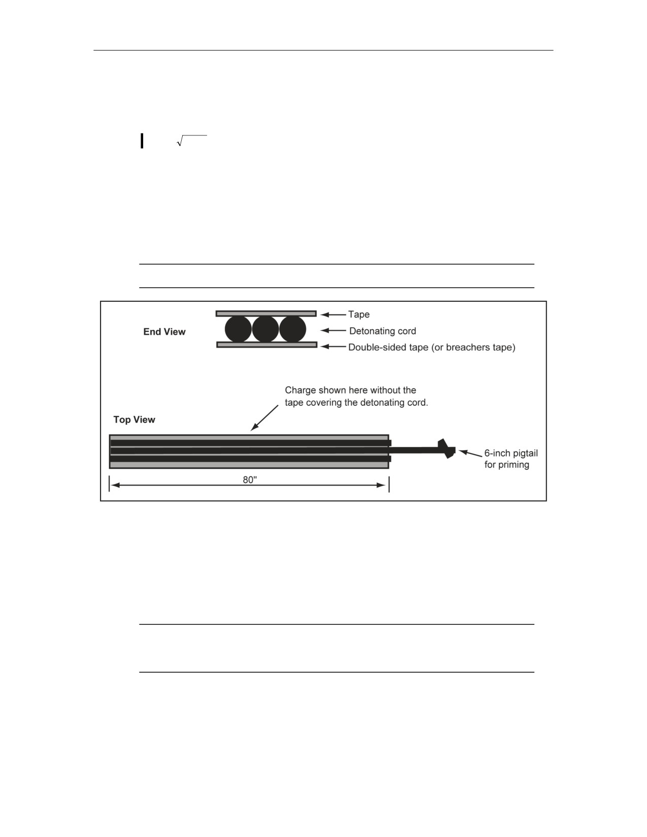
Explosive Urban Entry
1 x 19 x 1.60 = 30.4 gr of TNT
2,656 + 83 + 30.4 gr of TNT = 2,769.4 gr of TNT
2,769.4 ÷ 7,000 = 0.395 lbs of TNT = 0.4 NEW
0.4 + 10.05 = 10.45 NEW
3
MSD =
NEW * K factor
2.19 x 18 = 39.42 (round up to 40 ft)
Standoff = 40 feet without shielding; 20 feet with shielding
DETONATING CORD LINEAR CHARGE
7-20. The detonating cord linear charge (Figure 7-1) is an exterior charge which is effective against
wooden and metal doors that open inward and outward. The charge uses the blast principle to cut the
door along the length of the charge, thereby, defeating the attachment mechanisms and the security of
the door.
Note. It is recommended that both ends of all lengths of detonating cord be taped.
Figure 7-1. Detonating Cord Linear Charge
MATERIALS REQUIRED
7-21. Explosive materials required include 21 feet of 50-grain-per-foot detonating cord (this number
may vary depending on the door type; one 80-inch piece of detonating cord should be added for
security doors).
7-22. Nonexplosive materials required include 2-inch pressure-sensitive tape (duct tape) and double-
sided tape.
Note. Use three strips of detonating cord for all doors except extremely rugged security
doors. Use four strips when a very secure structure is encountered using security-type doors
of solid wood, such as an oak blank or ribbed metal.
CHARGE CONSTRUCTION
7-23. The following steps are used to construct a detonating cord linear charge:
z
Step 1. Cut a piece of double-sided tape 80 inches long. Peel one side, and lay the
tape flat on a table with the sticky side up.
27 August 2008
FM 3-34.214, C1
7-9

Chapter 7
z
Step 2. Cut and place a 92-inch piece of 50-grain-per-foot detonating cord strip down the
center of the double-sided tape, keeping the detonating cord as straight as possible. Ensure
that one end of the detonating cord is even with the end of the tape.
z
Step 3. Cut two 80-inch lengths of detonating cord (three for heavier metal doors) and place
one on each side of the 92-inch piece of 50-grain-per-foot detonating cord. Ensure that the
detonating cord is tight against each other for the entire length.
z
Step 4. Use duct tape, and cover the detonating cord and tape.
z
Step 5. Form a pigtail to aid in priming using the end of the 92-inch length of detonating
cord.
z
Step 6. Use duct tape to make a buddy tab (folded tape) at the top of the charge, and
continue to run the duct tape down the length of the paper covering. This ensures easier
separation of the end of the tape and its adhesive backing.
z
Step 7. Roll the charge, starting at the bottom with the paper side inward. This ensures the
ease of charge placement and keeps the tape covering from cracking or coming off.
CHARGE PLACEMENT
7-24. The charge can be placed on the hinge side, doorknob side, or in the center of the door. If placed
toward the door edge, do not place it closer than 4 inches from the edge. Exact placements will
determine the result of the cut. The following steps are used to place a charge:
z
Step 1. Peel off the double-sided tape backing when placing the charge on the target, and
attach the charge to the target from the top to the bottom.
z
Step 2. Pull the buddy tab down slightly from the top of the charge, and begin attaching the
tape to the door.
z
Step 3. Place the charge straight up and down (Figure 7-2) on the door. Place the charge as
close to the mechanism as possible to cut the door and allow entry.
Note. When placing the charge on the door locking mechanism side, not enough space may
be available to place the charge directly over the locking mechanism running parallel to the
doorframe.
z
Step 4. Prime the charge after it is attached to the door. This makes it much easier to unroll
the charge during emplacement without the shock tube becoming twisted.
Note. Placing the charge during wet conditions may cause the adhesive tape to be
ineffective. A secondary mounting method must be available if the tape backing does not
stick. Staples may be used for wooden doors and prop sticks may be used for any door type.
If time is available and the situation allows, cut any additional length off the charge to fit the desired
cut.
7-10
FM 3-34.214, C1
27 August 2008
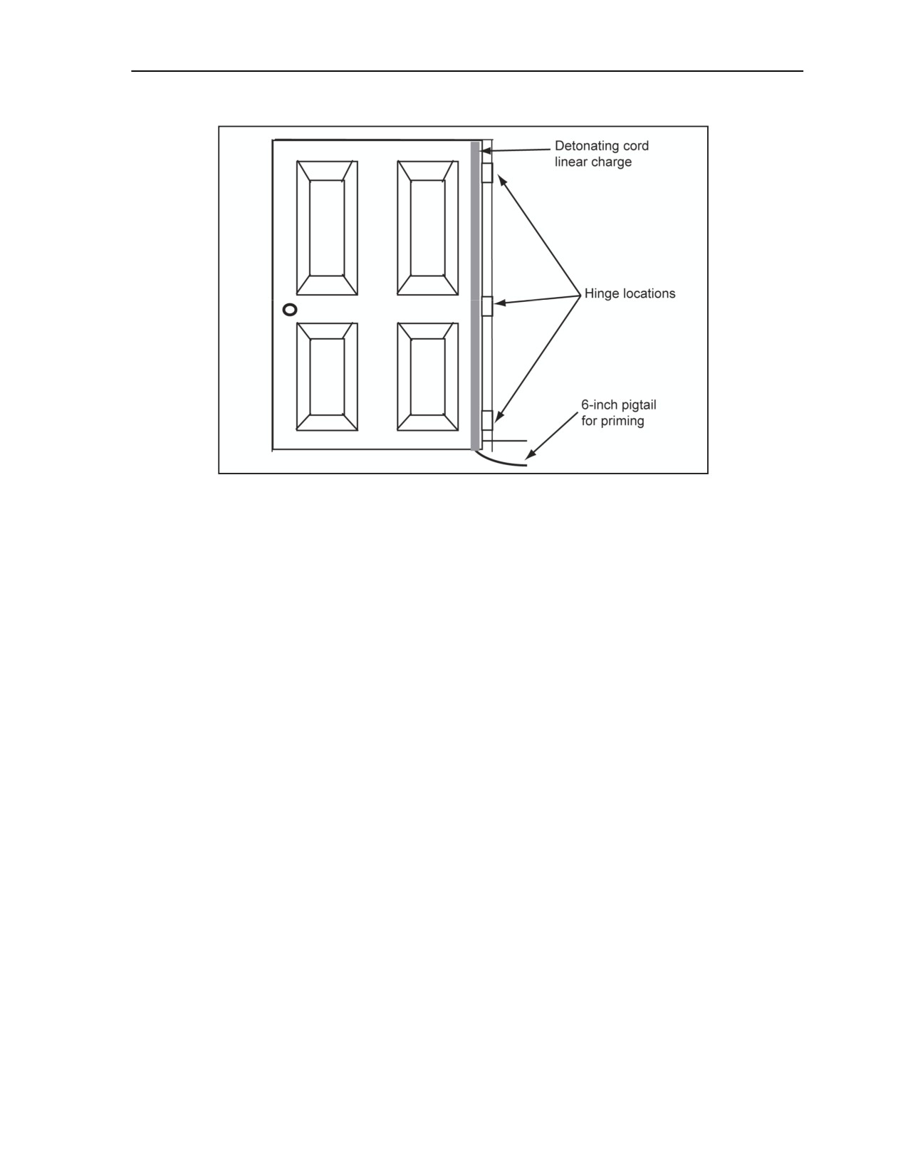
Explosive Urban Entry
Figure 7-2. Up-and-Down Charge
7-25. Hinge-side placement of the detonating cord linear charge is the preferred method for breaching the
door. Allowing the remaining portion of the door to fall inside the target structure may be considered a
hindrance to the entry.
7-26. Knob-side placement cuts the door and allows the door to swing open. This leaves most of the door
in the frame, but may allow the door to swing and hit the assault team.
7-27. When placing the charge vertically (centered on the door), the door is cut in half, removed from the
frame, and propelled within the structure. This could create fragmentation within the structure and could
also be a hazard to movement for the assault team.
ADVANTAGES AND DISADVANTAGES
7-28. Detonating cord linear charges have advantages and disadvantages.
Advantages.
It is compact when rolled, allowing for easy carrying.
One person can carry multiple charges.
It is designed to defeat a variety of doors and defeat barriers.
The charge is forgiving as to exact placement while still achieving desired results.
Disadvantages.
Some doorframes may prevent a complete cut.
Tape will not adhere well to wet or dirty surfaces.
Tape backing has a tendency to rip while being removed during charge placement.
OVAL (SILHOUETTE) CHARGE
7-29. The oval charge (Figure 7-3 and Table 7-4, page 7-12) is used against all wooden doors and selected
walls, such as those constructed of plywood, sheetrock, unfilled concrete block, and other lightly
constructed materials.
11 July 2007
FM 3-34.214
7-11
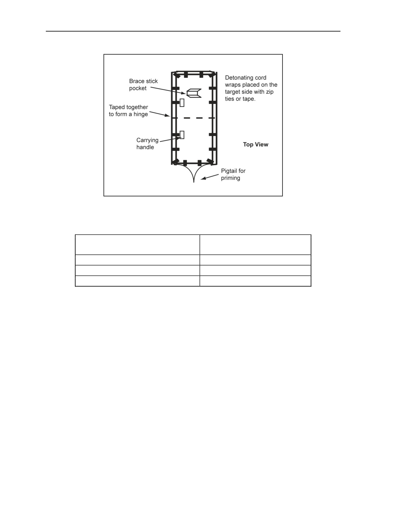
Chapter 7
Figure 7-3. Oval (Silhouette) Charge
Table 7-4. Target Thickness
Explosive
Target
(50-grain-per-foot detonating cord)
Wall, exterior lap siding, stud, or sheetrock
5 wraps
Wall, cinder block
8 wraps
Roof, shingle or plywood
6 wraps
MATERIALS REQUIRED
7-30. The following explosive and nonexplosive materials are required:
Explosive materials.
12-foot wraps of 50-grain-per-foot detonating cord.
Five wraps for an exterior wall (exterior lap siding, studs, or sheetrock) (four 12-foot pieces
of detonating and one 13-foot piece of detonating cord).
Six wraps for a roof (shingle or plywood) (five 12-foot pieces of detonating cord and one
13-foot piece of detonating cord).
Eight wraps for an unfilled cinder block wall.
Appropriate priming system.
Nonexplosive materials.
Duct tape.
Two E-type silhouettes.
One prop stick, if required.
Zip ties.
CHARGE CONSTRUCTION
7-31. The following steps are used to construct the charge:
7-12
FM 3-34.214
11 July 2007

Explosive Urban Entry
Step 1. Secure two E-silhouette targets. Cut one head off at the shoulders. Leave one head on at
what will be the charge bottom.
Step 2. Position the targets back-to-back with the green sides facing each other. Tape, with duct
tape, the targets together along the bottom edge of the two targets.
Step 3. Punch three holes, evenly spaced along the bottom of the targets, 1/4 to 1/2 inch up from
the bottom. Thread a zip tie through each hole, and tighten enough so as to leave a 1/2-inch gap.
This creates a hinge that allows the charge to fold easily.
Step 4. Cut a 2- by 5-inch rectangular hole 1 to 2 inches from the side and center through both
target pieces to create a carrying handle for the charge while it is folded.
Step 5. Open the hinge that was created, ensuring that the E silhouette with the head attached is
at the bottom.
Step 6. Create a prop stick holder by cutting a U shape 3 inches long by 4 inches wide about 4 to
6 inches in from the headless end. Ensure that the opening of the U faces the bottom of the
charge.
Step 7. Punch three evenly spaced holes about 1/4 inch from the edge along the side of each E
silhouette. Thread the zip ties through the holes of the E silhouette. Fasten the zip ties just tight
enough to stay closed. Ensure that the fastening head of the zip ties is over the edge of the E
silhouette so they will not interfere with the adhesion of the charge to the breaching target.
Step 8. Punch two holes in the top and bottom of the E silhouette in the same manner as the
holes punched in the sides. Ensure that these holes align where the shoulders of the target turn to
form a straight edge.
Step 9. Punch a pair of holes in the center of the head on the bottom of the E silhouette about
1/2-inch apart.
Step 10. Thread one zip tie down and back through the two holes in the head of the E silhouette.
Fasten the zip ties just tight enough to stay closed.
Note. Zip ties must be loose enough to thread multiple loops of detonating cord through them. If
zip ties are not available, a 3- to 4-inch piece of double-sided tape can be used. Tape over the
detonating cord with duct tape.
7-32. The following steps are used to attach the explosive:
Step 1. Start at the bottom, right-hand E-silhouette shoulder, and feed the running end of the
detonating cord through the zip ties to form a loop.
Note. Work each wrap of the loop from the center of the E silhouette towards the outside. Do not
feed through the zip tie on the head at this time. The type of obstacle construction material
determines the number of wraps. Five wraps of detonating cord for interior walls, studs, and
sheetrock; six wraps of detonating cord for roof shingles and plywood; and eight wraps of
detonating cord for block walls.
Step 2. When the determined number of wraps has been completed, feed the running end
through the zip tie in the head at the bottom of the E silhouette leaving a 1-foot tail.
Step 3. Pull enough detonating cord from the standing end (spool) to match the length of the
running end. Cut the standing end from the spool.
Step 4. Feed the cut end through the zip tie in the head in the same manner as before.
Step 5. Tighten the zip ties around the E silhouette working from the same point where the feed
started. Pull the slack towards the loose zip ties.
Step 6. Tighten the zip tie in the head.
Step 7. Cut off the ends of all the zip ties as close to the fastening head as possible.
Note. Tape the exposed ends of the zip ties to cover any sharp ends created by cutting them off.
11 July 2007
FM 3-34.214
7-13

Chapter 7
7-33. The following steps are used to construct a charge attachment system:
Step 1. Cut two pieces of double-sided tape 6 to 8 inches long.
Step 2. Remove the cover from one side of the tape. Attach one piece to the top of the charge
just below the prop stick U on the backside of the charge.
Step 3. Cover the protective cover of the remaining side with waterproof tape leaving a 1-inch
overhang folded against it to create a pull tab.
Step 4. Attach the second piece on the bottom of the charge in the center of the shoulder area on
the backside of the charge. Create a pull tab for this strip in the same manner as above.
Step 5. Cut a nonmetallic prop stick (such as a broom handle that is 2 by 4 inches) or a tree
branch to the proper size to hold the charge against the target.
WARNING
A prop stick may produce secondary fragmentation up to
100 meters to the rear. The doorknob and locking mechanism are
missile hazards. Failure to comply could result in immediate
personal injury or damage to equipment.
CHARGE PLACEMENT
7-34. The charge on the target with the E-silhouette head is placed as a standoff from the ground. The
charge is attached to the target with the head side down.
Remove the protective cover from the double-sided tape using the pull tab created during the
charge construction.
Push the charge backing material, adhesive side down, against the target ensuring that the
double-sided tape is adhered to the target.
Place the charge centered on the doors unless the doors are over 8 feet tall, then place the charge
about 1 foot above the floor.
WARNING
Placing the charge higher than 1 foot above the floor will create a
tripping hazard as a result of the blast. Failure to comply could
result in immediate personal injury or damage to equipment.
Note. Use a nonmetallic prop stick for heavier charges. Place one end of the stick against the
charge under the flap created during construction. Place the other end on the ground, and push it
towards the target to prop the charge against the target.
Place the charge on walls about 1 foot above the floor. Locate the wall studs before placement of
the charge.
Note. The charge is 19 inches wide when constructed from an E silhouette. The center of the
charge should be centered between the studs regardless of the stud spacing. Wall studs are
normally spaced at 16 to 24 inches on center.
7-14
FM 3-34.214
11 July 2007

Explosive Urban Entry
WARNING
A prop stick may produce secondary fragmentation up to 100
meters. Failure to follow proper procedures could result in
immediate personal injury or damage to equipment.
ADVANTAGES AND DISADVANTAGES
7-35. The following are the advantages and disadvantages of an oval charge:
Advantages.
It will provide an opening where one does not normally exist.
It is easy to make and employ.
Disadvantages.
It is difficult to move through rough terrain.
Transportability becomes a problem if the charge is constructed far away from the target.
It throws a considerable amount of debris and fragmentation into the target site.
CONCRETE CHARGE
7-36. The concrete charge uses the blast principle to breach concrete up to 19 inches thick. The information
in the paragraphs below should be applied.
MATERIALS REQUIRED
7-37. Concrete charge material required include 50-grains-per-foot detonating cord (Table 7-4, page 7-12).
Each wrap of the 50-grain-per-foot detonating cord should be 12 feet long. Material requirements include―
Explosive materials.
Six blocks of composition C4.
Thirty-two feet of 50-grain-per-foot detonating cord.
A dual-firing system.
Nonexplosive materials.
Backing material.
Tape.
A prop stick.
CHARGE CONSTRUCTION
7-38. The following steps are used to construct a concrete charge:
Step 1. Cut a 12-foot length of detonating cord (this will be the main line). Cut and tie the
remaining detonating cord to this line.
Step 2. Cut 12 pieces of detonating cord, each piece 18 to 20 inches long. Tie Uli knots on the
main line.
Step 3. Tape a block of composition C4 to the knots once the Uli knots are tied (one knot on
each end of the block). Ensure that the Uli knots slide if adjustments need to be made at the
target.
Step 4. Space the blocks evenly, but no more than 12 inches apart.
CHARGE PLACEMENT
7-39. The following steps are used to place a concrete charge:
Step 1. Place the charge flat against the target.
11 July 2007
FM 3-34.214
7-15
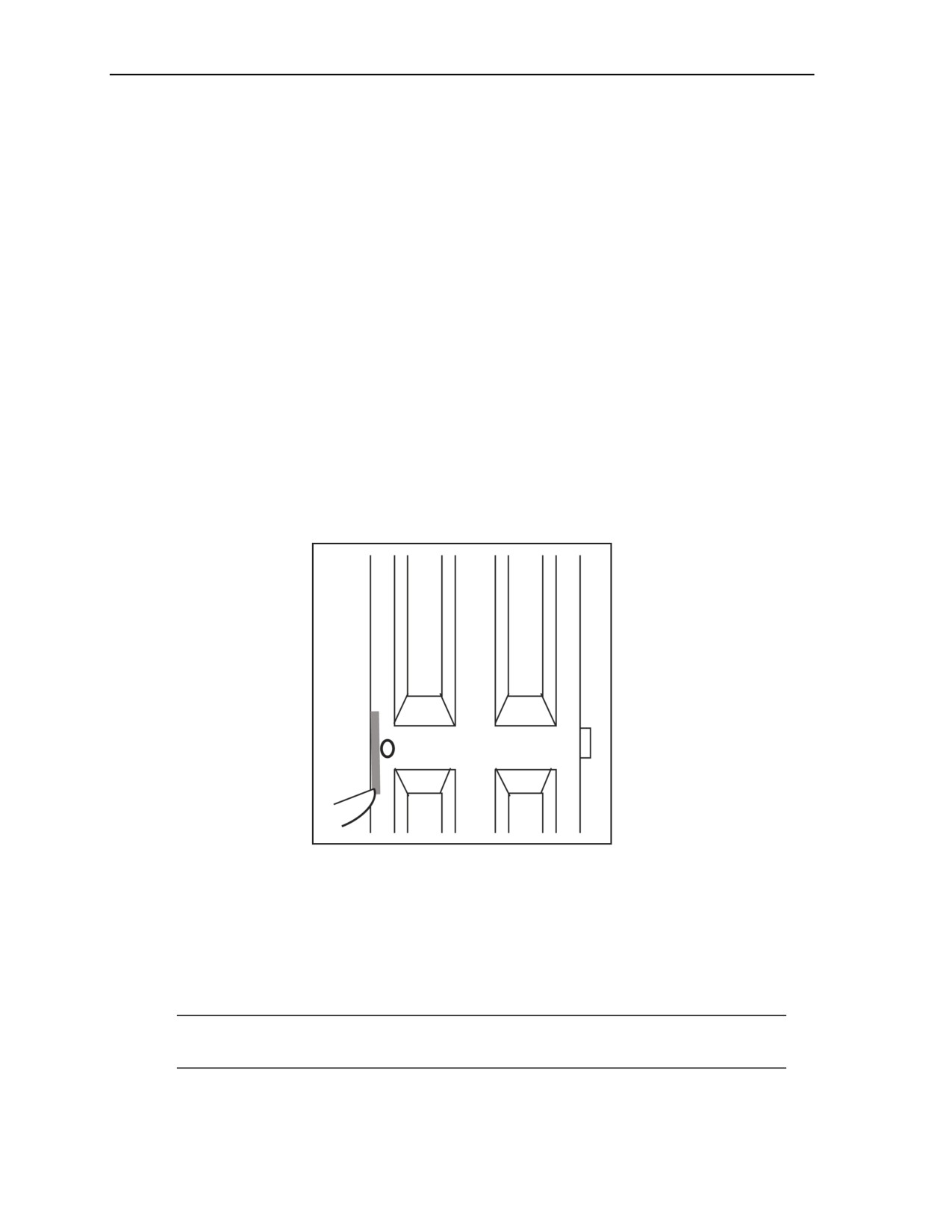
Chapter 7
Step 2. Pull the buddy tab, and attach the charge.
Step 3. Fire the charge.
ADVANTAGES AND DISADVANTAGES
7-40. The following are the advantages and disadvantages of a concrete charge:
Advantages.
It is relatively easy to employ.
The charge is versatile.
Anyone on the other side of the charge will be nonfunctional.
Disadvantages.
The charge has a high NEW.
The charge will not cut rebar or other reinforcement.
RUBBER-STRIP CHARGE (WINDOW CHARGE)
7-41. The rubber-strip charge can defeat the locking mechanism of wooden or metal doors (Figure 7-4) and
windows. When used on a door, the charge dislodges the locking mechanism from the frame and/or door.
When used on a window, the rubber-strip charge uses the power of explosives to push the window sash or
glass from the frame, thus creating a hole of entry without creating a large amount of fragmentation. The
design of the charge causes the explosives to detonate and in turn pushes a nonexplosive medium (rubber)
through the target. It is this pushing effect which limits the collateral damage created within the structure.
Figure 7-4. Placement of a Rubber-Strip Charge (Doors)
MATERIALS REQUIRED
7-42. Explosive materials required include 5 feet of 50-grain-per-foot detonating cord. For priming, add 1
foot of 50-grain-per-foot detonating cord.
7-43. Nonexplosive materials required include—
A medium 1- by 18-inch strip of Goodyear™ 330B rubber, belted, conveyer belt rubber.
Note. If these items are not available, the medium must be a material that will not disintegrate
when the detonation occurs, such as a truck mud flap or polystyrene cutting board.
Duct tape or electrical tape.
7-16
FM 3-34.214
11 July 2007
Explosive Urban Entry
Double-sided tape.
CHARGE CONSTRUCTION
7-44. The following steps are used to construct a rubber-strip charge (Figure 7-5):
Step 1. Cut a strip of rubber, or whatever is being used as a medium, 18 inches long by 1 inch
wide.
Step 2. Cut the detonating cord into two 18-inch strips and one 30-inch strip.
Step 3. Place the 30-inch piece of detonating cord in the center running lengthwise down the
rubber allowing 6 inches to hang over the 1-inch edge.
Step 4. Place an 18-inch strip on each side of the 30-inch piece of detonating cord to cover the
rubber.
Step 5. Tape both ends and the center with one to two wraps of electrical tape or equivalent-
sized strips of duct tape.
Step 6. Fold 6 inches of the detonating cord upon itself, and tape to make a 3-inch priming
pigtail.
Step 7. Place strips of double-sided tape on the rubber side of the charge. Use duct tape to make
a buddy tab (folded tape) at the top of the charge, and continue to run the duct tape down the
length of the paper covering to prevent the double-sided tape from tearing when the paper
backing is removed.
Figure 7-5. Rubber-Strip Charge Construction
DOOR CHARGE PLACEMENT
7-45. The following steps are used to employ the charge on a door:
Step 1. Attach the charge to the target by—
Removing the protective cover from the double-sided tape by pulling the buddy tab created
during charge construction.
Placing the charge on the door with the rubber side of the charge facing the target, between
the doorknob or any other locking mechanism and the doorjamb.
Adding additional tape, if necessary, to secure the charge to the door.
Step 2. Attach the initiation system by—
Turning the couplings of the two fuse igniters counterclockwise and removing the shipping
plugs from the igniters.
Cutting off the sealed end of the blasting cap assemblies and attaching the end to the fuse
igniters with the safety pins facing the same direction.
11 July 2007
FM 3-34.214
7-17
Chapter 7
Using the bight to attach the initiating system using an M9 or taping the blasting caps
directly to the bight formed with the detonating cord.
Step 3. Prepare to detonate the charge by—
Standing at a safe distance from the charge as determined by the breach team leader.
Firing the charge upon command from the breach team leader.
WARNING
The doorjamb will be the protective shielding when the charge is
fired. There is a chance that, if the charge can be seen, injuries
could occur by blasting fragmentation. Failure to follow proper
procedures could result in immediate personal injury or damage
to equipment.
WINDOW CHARGE PLACEMENT
7-46. To employ the charge on light residential windows, the buddy tab is removed exposing the double-
sided tape, and the charge is placed on the window (Figure 7-6). The following steps are used:
Step 1. Place the charge on the side stiles with the rubber side of the charge facing the target.
Ensure that the charge overlaps the meeting rails and both sashes. (Charges placed horizontally
on the meeting rails may result in the rails being blown out and most of the glass and sashes
remaining in place.) Place the charge along the side stiles and across the meeting rails to push
the stiles out of the window frame, thus removing the sashes from the window.
Note. It is not necessary for the entire length of the charge to be touching the window stile. If the
charge is placed on a double-hung window, the bottom portion can be pushed in to touch the
inner window stile or it can be left hanging. The results will be the same.
Step 2. Add additional tape, if necessary, to secure the charge to the window.
Step 3. Back off to a safe distance, and initiate the charge.
Step 4. Be prepared to break and rake any glass left in the window frame after detonating.
Figure 7-6. Placement of a Rubber-Strip Charge (Windows)
7-47. For a casement window, place the charge is placed vertically on the mullion (Figure 7-6). This
placement will remove the mullion and break the glass. You should—
7-18
FM 3-34.214
11 July 2007

Explosive Urban Entry
Add additional tape, if necessary, to hold the charge in place.
Back off to a safe distance, and initiate the charge.
Ensure that employment of the charge is followed up with a break and rake of the remaining
glass.
7-48. On heavier store-type windows (Figure 7-6), the charge should be placed on the bottom of the
window in the corner (with the rubber side of the charge facing the target). You should—
Add additional tape, if necessary.
Back off a safe distance, and initiate the priming system.
Note. The explosive will push the medium through the target, removing the glass from the
bottom of the window. The window will fall down under its own weight.
Be prepared to break and rake any glass left in the frame after the charge detonates, since the
commercial window is large.
Note. If attacking a larger window, two charges placed end to end in the corner may be needed.
ADVANTAGES AND DISADVANTAGES
7-49. Advantages and disadvantages of a rubber-strip charge includes the following:
Advantages.
They are a small compact charge.
They are easy to make.
They are easy to employ.
The charge can be placed quickly.
They have a very low NEW, producing minimal lethal fragmentation.
Disadvantages.
Fragmentation created from a commercial window.
Break and rake may be required if the charge does not completely remove the glass from
the window frame.
WATER CHARGE
7-50. This charge (Figure 7-7, page 7-20) is primarily used on metal or steel doors. The charge should be
centered on the door to buckle it, causing the locking mechanism to slide out of the strike plate. The fluids
in the intravenous (IV) bags act as force and tamp devices. When placed on solid wooden doors, it must be
placed over the locking mechanism.
11 July 2007
FM 3-34.214
7-19
Chapter 7
Figure 7-7. Water Charge
MATERIALS REQUIRED
7-51. The following explosive and nonexplosive materials are required:
Explosive materials.
11 feet of 50-grain-per-foot detonating cord or 12 feet with a priming system.
A priming system of your choice.
Nonexplosive materials.
550 cord.
Double-sided tape or breachers tape.
Suitable backing material (cardboard).
Duct tape and electrical tape.
Prop stick.
Two each, 500- or 1,000-milliliter IV bags.
CHARGE CONSTRUCTION
7-52. The following steps are used to construct a water impulse charge:
Step 1. Prepare the material for charge construction.
Do not remove the outer lining from two IV bags. This provides added protection to the IV
bags to prevent leaking and will not affect the result of the charge.
Cut a piece of backing material 4 by 8 inches or equal to the size of the IV bag.
Note. Backing material should be the size of the IV bag. Any heavy cardboard will work. The
backing material provides a flat surface area to attach the charge to the target.
Cut a 3-foot and an 8-foot piece of detonating cord.
Fold the
8 foot piece in half four times for
500-milliliter bags and three times for
1,000-milliliter bags.
Center the 3-foot section of detonating cord lengthwise in the center of the 8-foot folded
section.
7-20
FM 3-34.214
11 July 2007

Explosive Urban Entry
Tape the folded detonating cord tightly around the 3-foot section with electrical tape, and
then cover it with waterproof tape.
Tape the backing material to one of the two IV bags.
Note. Ensure that the backing material maintains a flat face and is not curved from taping. If
curved, it will reduce the charge-to-target contact area.
Step 2. Attach the explosive.
Center the detonating cord onto one IV bag, and tape it in place with 2 or more wraps of
electrical tape.
Note. Taping the detonating cord in place will keep it from pulling out as the charge is
constructed.
Place the second IV bag facing the same direction on top of the first, and tape it tightly to
the first bag. Ensure that the detonating cord is sandwiched between the two IV bags.
Protect the IV bags by taping them entirely with duct tape.
Note. Ensure that the backing material remains flat so that the breachers tape or double-sided
tape can be placed on the charge to secure the charge to the target.
Step 3. Construct the charge attachment system.
Construct a bridle for the water charge by cutting 3 foot of 550 cord and tying an overhand
knot about 3 inches from each end. This assists in holding up the charge.
Note. This bridle will allow the charge to hang from a prop stick.
Place one end of the cord along one side of the charge. Secure it to the charge with duct
tape just above the knot.
Run the tape halfway around the charge. Form a loop with the 550 cord, and place the
opposite end along the other side of the charge. Secure it to the charge by running the tape
the rest of the way around the charge and over the 550 cord just below the knot.
Fold the ends of the cord below the knots back over the tape, and cover the cord ends with
more tape.
Note. The reversing of the cord will ensure that it does not pull out from under the tape.
Cover the entire face of the backing material with double-sided tape.
Peel back the protective cover, and run a strip of duct tape across the top and bottom one-
half inch of the double-sided tape. Run this strip of tape onto the charge.
Note. This strip ensures that the duct tape does not come off in adverse weather.
Tape the two free ends of the detonating cord together to allow for the priming system
hook-up. Use electrical tape at the ends and about 3 inches up on the detonating cord.
Cut a prop stick to an appropriate length, and notch it to hold the 550 cord.
CHARGE PLACEMENT
7-53. The following steps should be used to attach the charge to the target:
Step 1. Cut a prop stick to an appropriate length, and notch it in the middle to hold the 550 cord.
Step 2. Attach the charge to the target using one of the following methods:
11 July 2007
FM 3-34.214
7-21

Chapter 7
Inward-opening wooden doors. Place the charge by setting it on top of the doorknob and
prop it up with a stick.
Note. This allows for more support of the charge with the capability to defeat the door even if it
has a dead bolt.
Metal doors. Place the charge centered both horizontally and vertically on the door
(Figure 7-8).
Note. The normal tendency is to place the charge too high. It takes practice to ensure the proper
placement of the charge. When fired, the hydraulic pressure buckles the center of the door
causing the locking and closing mechanism to slide out of the strike plate and opening the door.
In most cases, it will rip the entire door from the frame.
Metal security doors. Place the charge next to the locking.
Note. A metal security door is constructed of 14- or 16-gauge steel and contains steel ribs
running vertically between the door panels. A centered charge will not defeat this door because
the ribs strengthen the door and keep it from buckling. Placing the charge next to the locking
mechanism defeats the locking mechanism and allows the door to open.
Outward-opening doors. Place the charge centered horizontally and vertically on the door.
(As with the inward opening door, the door will buckle. In this case the door will bounce
off the door jam and open.)
Screen doors. Place the charge directly on the screen door in the position it would be
placed for the door type located being the screen door.
DANGER
A prop stick may produce secondary fragmentation up to 100
meters to the rear. The doorknob and locking mechanism are
missile hazards. Failure to follow proper procedures may cause
death or permanent injury.
7-22
FM 3-34.214
11 July 2007
Explosive Urban Entry
Figure 7-8. Placement of a Water Impulse Charge (Metal Door)
ADVANTAGES AND DISADVANTAGES
7-54. The advantages and disadvantages of a water impulse charge include the following:
Advantages.
It is a small or compact charge.
It is easy to construct.
It has a low NEW.
It has some fragmentation.
Disadvantages.
There is a chance of bags leaking between the assembly area and the target site.
The weight could become a factor if carrying it for a long distance.
C-CHARGE
7-55. The C-charge can be used to open a solid wood door or a metal door. The charge cuts the lock out of
the door.
MATERIALS REQUIRED
7-56. Explosive materials required include 6.5 feet of 50-grain-per-foot detonating cord. Nonexplosive
materials required include duct tape, cardboard, and double-sided tape.
11 July 2007
FM 3-34.214
7-23

Chapter 7
CHARGE CONSTRUCTION
7-57. The following steps are used to construct a C-charge (Figure 7-9):
Step 1. Prepare the material for charge construction.
Cut the backing material in about an 8-inch square.
Note. Backing material should be a relatively heavy cardboard.
Apply double-sided tape along three edges of the backing material forming a C shape.
Ensure that the closed end of the C is in line with one edge of the backing material.
Note. Leave the protective cover on the outside of the tape until ready to apply the detonating
cord.
Cut the required amount of detonating cord long enough to form a C on the outer edge of
the C created with the double-sided tape.
Note. To help with the measurement for the correct length of detonating cord, lay the first piece
of cord along the outer edge of the C created by the double-sided tape. Follow the outer edge of
the C starting at the top of the opening. Travel along the outer edge of the backing material and
return to the bottom of the opening. Cut off the first piece.
Use the length of the first piece of detonating cord, and cut a template. Cut the remaining
number of pieces of detonating cord for the charge.
Cut a 30-inch length of detonating cord, and set it aside. Use this piece to prime the charge.
Step 2. Attach the explosive.
Remove the protective cover from the double-sided tape, and press the first piece of
detonating cord in place along the outside edge of the double-sided tape. Form a C shape,
ensuring that the closed end of the C is in line with the back edge of the backing material by
pressing them one piece at a time inside the previous piece working towards the center.
Place the correct number of detonating cord pieces (4 to 10).
Tape the detonating cord to the double-sided tape with electrical tape every 2 to 4 inches,
starting about 2 inches in from the opened end of the C.
Trim the ends of the detonating cord evenly on both sides.
Step 3. Prime the charge.
Form a bight in the 30-inch piece of detonating cord previously cut by bending it in half.
Connect the two lengths of detonating cord by wrapping a piece of electrical tape around
both lengths about 4 inches from the end of the bight.
Line the ends of the two lengths of detonating cord up with the ends of the detonating cord
that make up the charge. Prime the charge by laying the lengths of detonating cord on top of
the charge and holding it in place with duct tape.
Cover all the detonating cord with waterproof tape. Ensure that the detonating cord is
completely covered with the tape.
Step 4. Construct a charge attachment system.
Ensure that the charge is facing up, and mark a spot on the backing material in the center of
the C about 2 1/5 inches from the edge of the backing material with the opened side of the
C.
Make cuts 2 to 3 inches long forming a star at the spot marked on the backing material.
(This will form an area to press the charge over the doorknob.)
7-24
FM 3-34.214
11 July 2007
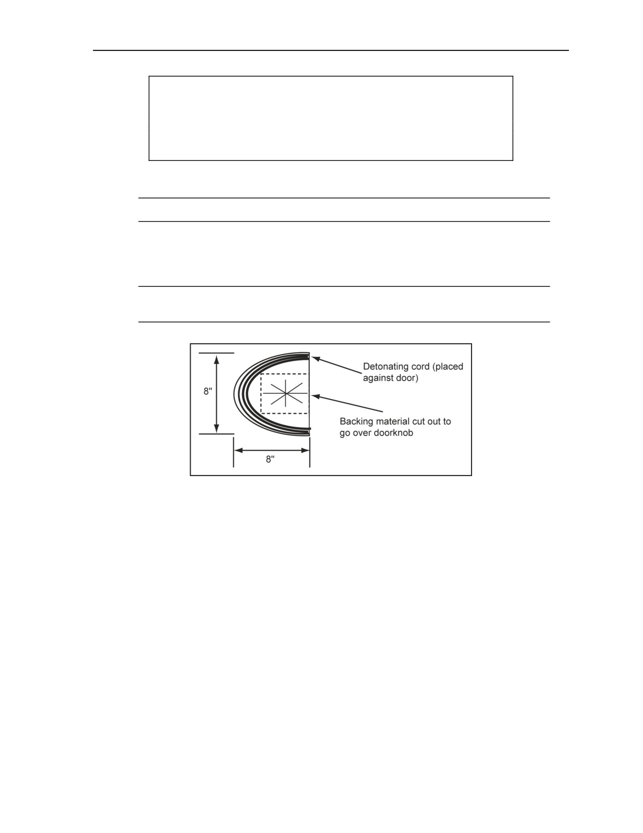
Explosive Urban Entry
CAUTION
Do not cut closer than 1 inch from the straight edge of the charge.
Personal injury or damage to equipment may result from long-term
failure to follow correct procedures.
Apply double-sided tape to the back of the charge on three sides of the backing material
forming a C in the same manner as the front side.
Note. Leave the protective cover on the outside of the tape.
Apply waterproof tape to the protective cover of the double-sided tape. Cut the waterproof
tape the same width as the double-sided tape so it does not overlap and stick to the backing
material. Extend the waterproof tape about 1 inch past the edge on the topside of the C
opening, and fold it back against itself forming a pull tab.
Note. This will allow quick removal of the protective cover from the double-sided tape so the
charge can be stuck to its target.
Figure 7-9. C-Charge Construction
CHARGE PLACEMENT
7-58. The charge is placed on the doorknob or locking mechanism (Figure 7-10, page 7-26). The charge is
secured in place with double-sided tape. The detonating cord must be held firmly against the surface of the
door. The charge should be attached to the target by—
Removing the protective cover from the double-sided tape just before placing the charge.
Pushing the star previously cut in the backing material, adhesive side down, over the doorknob.
Ensure that the open side of the C faces the door edge.
Pressing the charge tightly against the door ensuring that the double-sided tape is adhered to the
door.
11 July 2007
FM 3-34.214
7-25
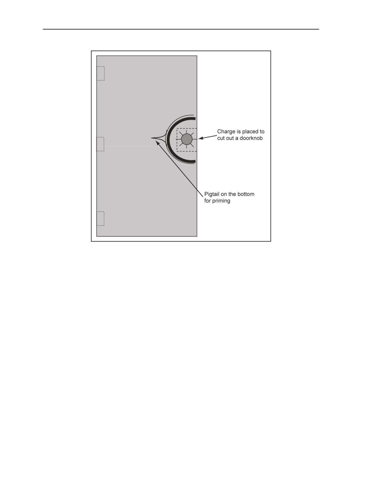
Chapter 7
Figure 7-10. Placement of a C-Charge (Door)
ADVANTAGES AND DISADVANTAGES
7-59. The following are the advantages and disadvantages of a C-charge:
Advantages.
It is a small or compact charge.
It is easy to construct.
It has a low NEW.
There is very little fragmentation
Disadvantages. Incorrect placement can cause a breach to fail.
DOUGHNUT CHARGE
7-60. The doughnut charge (Figure 7-11) can open a solid wood door or a metal door. The charge cuts the
lock out of the door and is the only interior breaching charge.
7-26
FM 3-34.214
11 July 2007
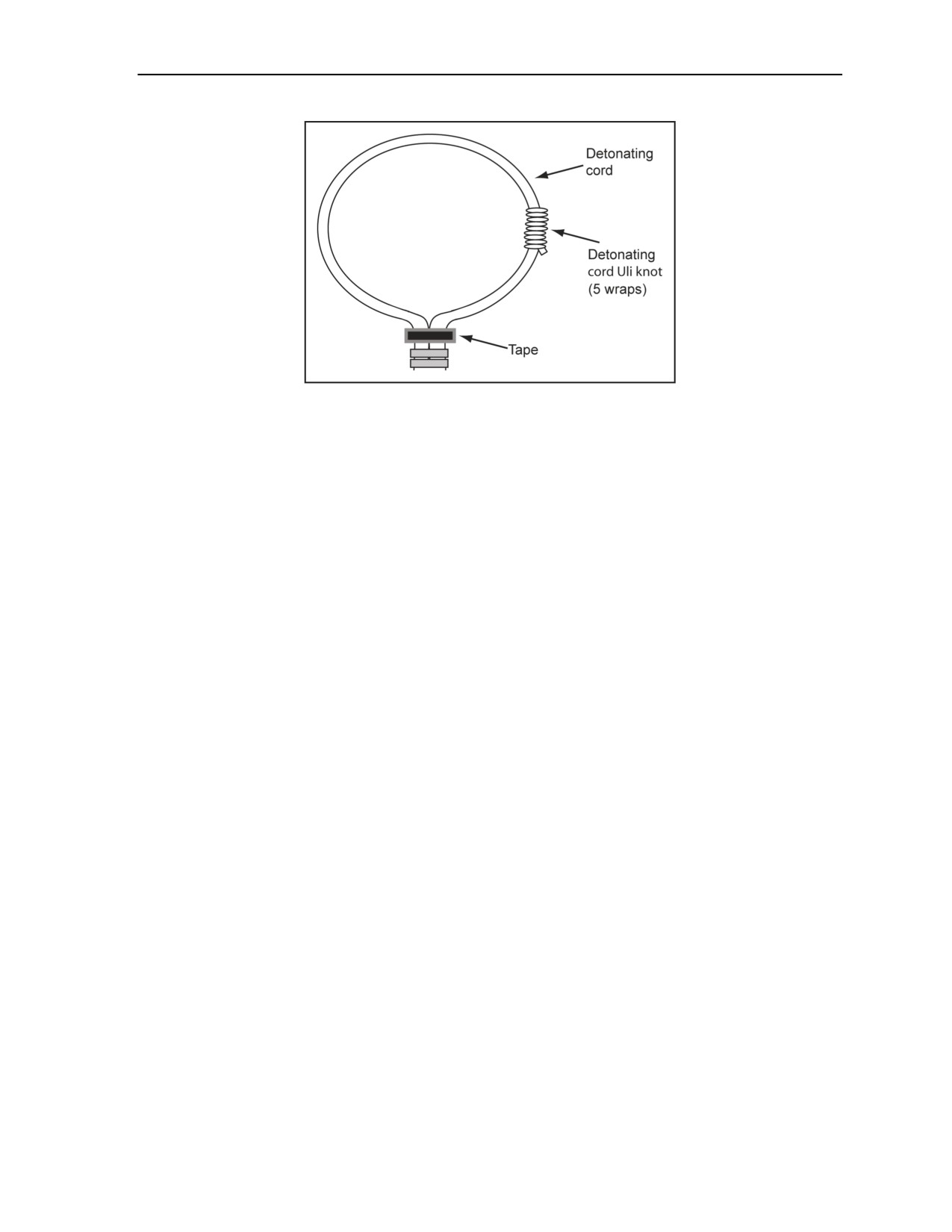
Explosive Urban Entry
Figure 7-11. Doughnut Charge
MATERIALS REQUIRED
7-61. Explosive materials required include 42 inches of 50-grain-per-foot detonating cord. Nonexplosive
materials required include duct tape.
CHARGE CONSTRUCTION
7-62. The following steps are used to construct a doughnut charge:
Step 1. Cut one 18-inch piece of 50-grain-per-foot detonating cord.
Step 2. Cut one 24-inch piece of 50-grain-per-foot detonating cord.
Step 3. Use a 24-inch piece of detonating cord to tie an Uli knot (5 wrap) onto the 18-inch piece
of detonating cord. Fold that same 18-inch piece of detonating cord to form a loop. Use electrical
tape to tape the ends of the detonating cord together.
Step 4. Use a piece of duct tape, and make a sliding tape knot on the detonating cord loop. To do
this, take a 6-inch strip of tape, fold a 2-inch section over upon itself to create a nonstick surface,
and wrap the tape around the detonating cord. Continue wrapping until the tape is finished.
Ensure that the tape knot slides easily on the detonating cord loop. Finally, slide the tape toward
the ends of the loop to provide enough room to slide the loop over a doorknob.
Step 5. Ensure that both the Uli knot and tape slide freely.
Step 6. Construct and attach a priming system at the running ends of the loop.
CHARGE PLACEMENT
7-63. The following steps are used to place the doughnut charge on the target:
Step 1. Loop the charge over the doorknob.
Step 2. Slide the large Uli knot to one side of the detonating cord loop.
Step 3. Slide the knot to the side if the detonating cord loop has a natural bend, which will allow
the natural bend to curve toward the door.
Step 4. Place the detonating cord loop over the doorknob so that the Uli knot is between the
doorknob and the doorjamb.
Step 5. Position the Uli knot over the throw of the knob.
Step 6. Slide the tape knot toward the loop so that the loop is tightened onto the doorknob.
Step 7. Place the natural bend of the detonating cord toward the door to ensure that the blasting
cap is pushed into the door, providing the protection of the doorjamb between the breacher and
the charge.
Step 8. Take cover, and initiate the priming system.
11 July 2007
FM 3-34.214
7-27
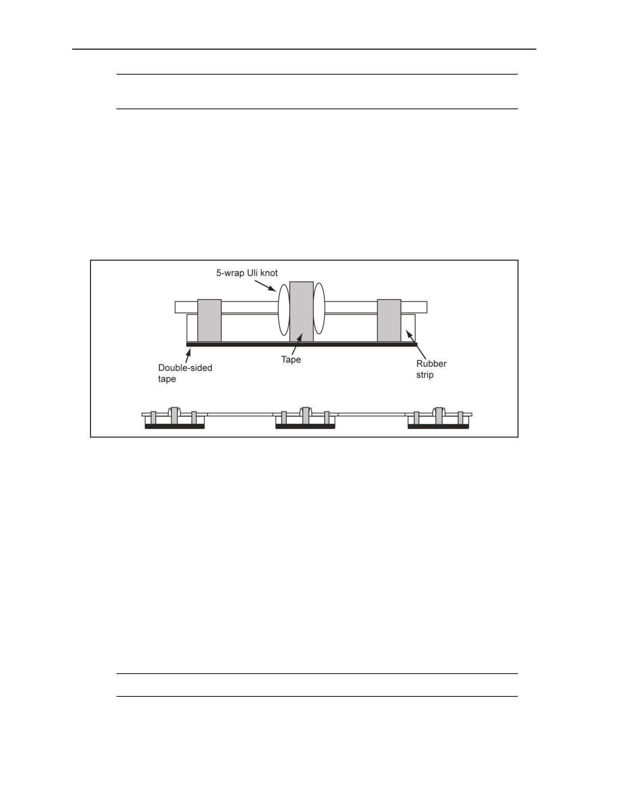
Chapter 7
Note. This is the only breaching charge that is direct-primed (no detonating cord loop). To
reduce the NEW (this is an internal charge), this charge is single-primed.
ADVANTAGES AND DISADVANTAGES
7-64. The advantage of the doughnut charge is that it is easily constructed and carried, and one individual
can easily carry multiple charges.
7-65. The disadvantage of a doughnut charge is that incorrect placement can cause a breach to fail.
ULI KNOT SLIDER CHARGE
7-66. The Uli knot slider charge (Figure 7-12) may be used against inward- and outward-opening doors
made of either wood or metal. This charge is very effective, and at the same time, produces minimal
collateral damage. The Uli knot (5-wrap) must slide freely.
Figure 7-12. Uli Knot Slider Charge
MATERIALS REQUIRED
7-67. Explosive materials required include 18 feet of 50-grain-per-foot detonating cord. For a detonating
cord loop, add 1 foot of 50-grain-per-foot detonating cord.
7-68. Nonexplosive materials required include—
Duct tape.
Electrical tape.
Three 1- by 5-inch pieces of flat rubber (or suitable material, such as a material that is able to
convert the blast dynamic pressure into impulse pressure without disintegrating). For example, a
truck mud flap, a plastic cutting board, or a truck tire.
CHARGE CONSTRUCTION
7-69. The following steps are used to construct a Uli knot slider charge:
Step 1. Use a sharp knife to cut three 1- by 5-inch strips of rubber.
Step 2. Cut one 8-foot piece of 50-grain-per-foot detonating cord.
Note. Testing has found that 96 inches will cover most standard and nonstandard doors.
Step 3. Cut twelve 5-inch pieces of 50-grain-per-foot detonating cord.
7-28
FM 3-34.214
11 July 2007

Explosive Urban Entry
Step 4. Cut the remaining 50-grain-per-foot detonating cord into three equal length pieces.
Ensure that each piece is 24 inches long.
Step 5. Use electrical tape or duct tape to secure four 5-inch pieces of detonating cord onto one
side of a 1- by 5-foot strip of rubber. Ensure that an untaped area is left on the top center of the
detonating cord (where the Uli knot will lay). Repeat this step for the other two pieces of rubber.
Step 6. Use the 24-inch pieces of detonating cord to tie three Uli knots onto the 8-foot piece of
detonating cord. Ensure that the Uli knots slide freely on the 8-foot section of detonating cord.
Step 7. Secure the Uli knots to the rubber pieces with tape.
Step 8. Cut three 1- by 5-inch pieces of double-sided tape, and attach them to the bottom of the
three charge bodies. Ensure that the buddy tabs are made for ease of removal of the tape
backing.
Step 9. Tie an overhand knot in one end of the 8-foot piece of detonating cord to prevent the
charge bodies from sliding off.
Step 10. Fold 6 inches of the other end of the 8-foot length of detonating cord upon itself, and
tape it to make a 3-inch priming pigtail.
CHARGE PLACEMENT
7-70. Depending on the situation, remove the protective backing either in the safe area or en route to the
target. Place the Uli knot slider charge on the target in the following manner:
Place the charge bodies on the door parallel to the hinges on an outward-opening door (hinges
exposed).
Place the charge bodies on the door as close to the suspected hinge positions as possible on an
inward opening door (hinges not exposed). Typical hinge placement on doors is as follows:
Top hinge—about 7 to 9 inches or one hand length down from the top.
Center hinge—centered between the top and bottom hinge, about one hand height above the
doorknob.
Bottom hinge—about 10 inches up from the bottom.
Note. When encountering entrances that have screen or storm doors in front of the main door,
place the charge bodies on the screen or storm door so that the medium will impact the main
door next to the main door hinges. The intent is not to defeat the screen or storm door. It is
irrelevant as to which side the hinges are on. The attack is on the main door. The only real
difference is that there is now a standoff created by the screen or storm door, and greater care
will have to be used in the placement of the charge bodies in order to hit the target points.
ADVANTAGES AND DISADVANTAGES
7-71. The advantages and disadvantages of a Uli knot slider charge include the following:
Advantages.
It is easily adjusted at the target to be able to compensate for different hinge placement.
It can be effectively used against targets with screen or storm doors.
It can effectively be used against targets with multiple dead men (braces or barriers) on the
inside of the door.
Disadvantages.
The Uli knot slider charge is extremely violent on the target.
When incorrectly placed on wood doors, the medium becomes a hazard to personnel within
range of the target.
Incorrect placement, especially on inward-opening wooden doors, can cause a breach to
fail.
11 July 2007
FM 3-34.214
7-29
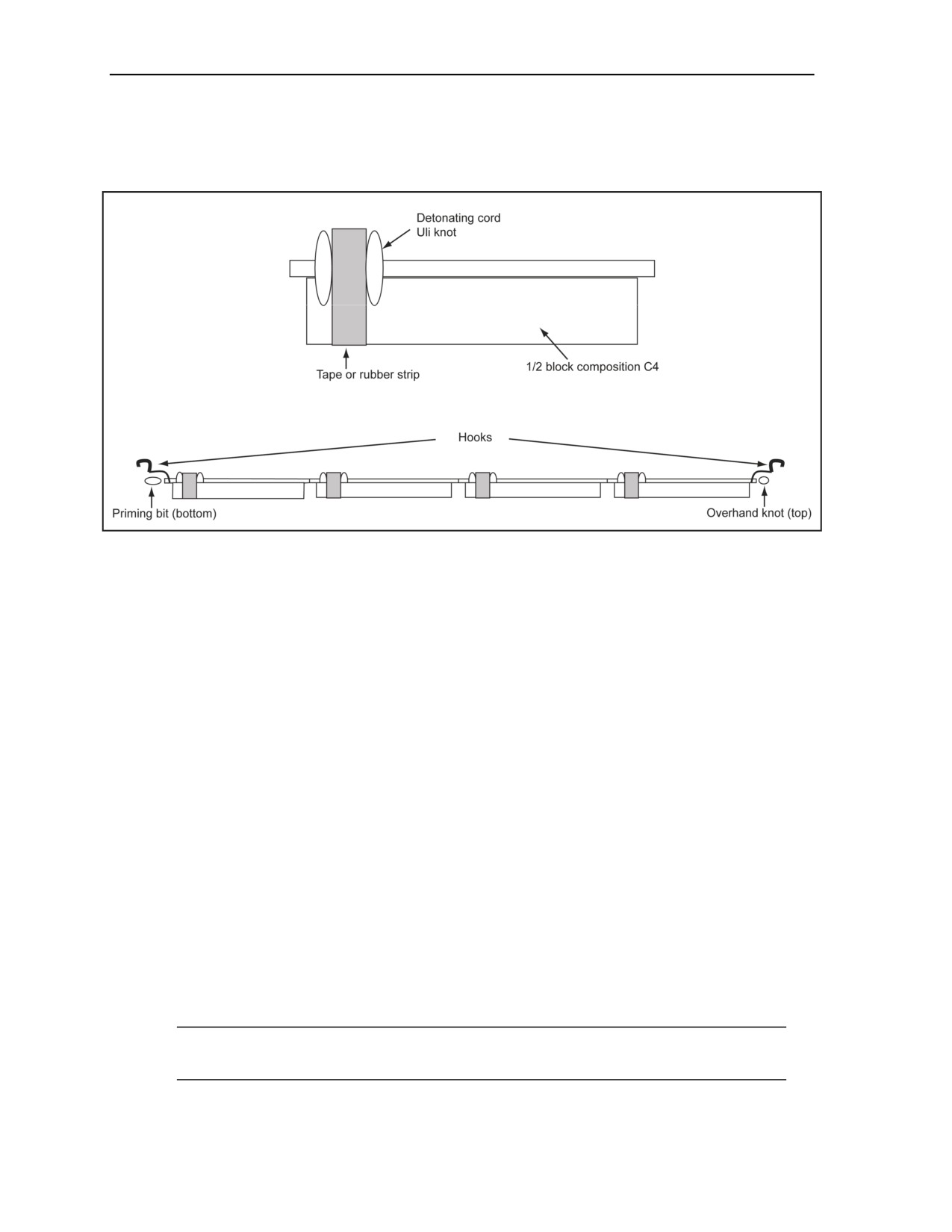
Chapter 7
FENCE CHARGE
7-72. The fence charge (Figure 7-13) is used against heavy-gauge-metal fence material, such as chain link.
This charge will work on other fence materials to create a hole for an assault element.
Figure 7-13. Fence Charge
MATERIALS REQUIRED
7-73. Explosive and nonexplosive material required includes—
Explosive material.
14 feet of 50-grain-per-foot detonating cord.
4 M112 composition C4 blocks.
Nonexplosive material.
2 treble hooks or nails.
4 inches of surgical tubing or a thick rubber band.
Electrical tape.
Duct tape.
CHARGE CONSTRUCTION
7-74. The following steps are used to construct a fence charge:
Step 1. Cut four 21-inch pieces of detonating cord (this should leave one remaining 7-foot piece
of detonating cord).
Step 2. Cut off 1 foot of detonating cord to use as a priming bite, leaving one 6-foot piece.
Step 3. Use the four pieces of detonating cord, and tie four separate Uli knots onto the 6-foot
piece of detonating cord.
Step 4. Tie an overhand knot at one end of the 6-foot strand of detonating cord, ensuring that
there is an additional 2 to 3 inches of detonating cord from the knot to the end of the detonating
cord.
Note. This provides an explosive area to secure a treble hook or nail. The knot prevents any
explosives from sliding off of the main line. This end is called the top end.
7-30
FM 3-34.214
11 July 2007

Explosive Urban Entry
Step 5. Take the end of the detonating cord without the knot, and fold it over to form a priming
bite. Secure it firmly with electrical tape (called the bottom end).
Step 6. Cut each M112 block lengthwise, making two 1- by 1- by 11-inch pieces out of each
block (four half blocks total). Cover the cut piece with duct tape to keep the composition C4
from falling apart. Leave one end of each piece uncovered. (This is where the 5-wrap Uli knot
will be attached.)
Step 7. Place the first composition C4 block onto the detonating cord touching the overhand
knot. Position the Uli knot on the composition C4 at the bottom edge. Cut out a notch for the Uli
knot. Place the excess composition C4 around the Uli knot before taping to the main line. Ensure
that it is deep enough so that the main line of detonating cord is at least flush with the
composition C4. Firmly tape the entire composition C4 block to the Uli knot and detonating
cord. Ensure that the Uli knot slides freely.
Step 8. Position the Uli knot as the previous one, and tape the entire block in place no more than
5 inches below the first composition C4 block position and the second composition C4 block.
Continue this procedure with the remaining composition C4 blocks and Uli knots.
Step 9. Use tape to attach a treble hook to the top end of the detonating cord on the composition
C4 side. Ensure that this is secure enough to hold the entire charge with tension placed on it. If
using a nail, bend the nail to a 45° angle, and secure it in place. Ensure that the hook points
toward the bottom end of the charge.
Step 10. Secure one end of the surgical tubing or rubber band to the detonating cord just below
the bottom-composition C4 block.
Step 11. Attach a second hook or nail to the surgical tubing or rubber band. Use the nails or
hooks to secure the charge to the fence.
ADVANTAGES AND DISADVANTAGES
7-75. The following are the advantages and disadvantages of a fence charge:
Advantages.
It provides quick access through the fence.
It is easy and quick to construct.
It has rapid placement.
Disadvantages.
It is a high-net explosive charge.
It has a high amount of fragmentation.
It may need mechanical backup.
RAPID WALL-BREACHING KIT
7-76. The rapid wall-breaching kit (RWBK) provides a capability that is preformed, prepackaged, easily
and rapidly employed, lightweight, and safe. The RWBK consists of commercial explosive cutting tape
(ECT) initiated by an MDI. The kit provides an explosive means to create man-sized holes rapidly in
buildings and in walls for dismounted mobility in urban and complex terrain environment, to rapidly cut
steel and other materials to breach obstacles, and to create obstacles to deny or impede enemy mobility.
INITIATION SYSTEM USING A MODERNIZED DEMOLITION
INITIATOR
7-77. The initiation devices used are an important part of urban breaching. The charges used should be
command detonated, and all charges should be dual-initiated with the exception of the doughnut charge.
See Figure 7-14, page 7-32.
11 July 2007
FM 3-34.214
7-31