FM 3-34.214 (FM 5-250) EXPLOSIVES AND DEMOLITIONS (July 2007) - page 4
Chapter 7
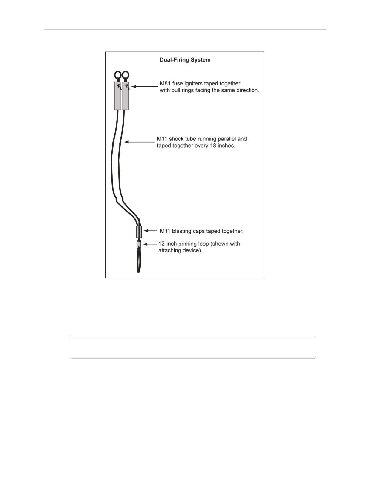
Figure 7-14. Initiation System Using MDIs
MATERIALS REQUIRED
7-78. The following are the materials required for an MDI:
Explosive materials (such as M19, M81, M11, M12, M13, M21, or M23).
Nonexplosive materials (such as electrical tape, string, or rubber bands).
Note. Use the M19 for the initiation system. When the M19 is not available, construct an
initiation system.
CONSTRUCTION
7-79. Use the following steps when constructing an MDI initiation system:
Step 1. Turn the screw cap of the M81 fuse igniters several turns counterclockwise, and remove
the shipping plugs from the igniters.
Step 2. Cut off the sealed end of the M11, M12, M13, M21, or M23 branchlines, and attach to
the M81 igniters with M81 safety pins facing the same direction.
Step 3. Tape an M11, M12, M13, M21, or M23 every 18 inches to improve efficiency.
Step 4. Tape an 18- to 24-inch length of detonating cord to the M11, M12, M13, M21, or M23
blast caps so they overlap and the detonating cord forms a loop.
7-32
FM 3-34.214
11 July 2007

Explosive Urban Entry
BREACHERS BRIEF
7-80. All elements of the brief should be covered. The following format should be used:
Primary target. Give a full description of the primary target or targets if a multiple breaches are
planned. Discuss the target type (such as the door or window) and where the target is located in
relation to the position and the surrounding area.
Alternate target. Determine if there is an alternate target. Determine what will be the alternate
target if the primary target cannot be accessed. Be sure to describe this target in detail, by type,
the location, and surrounding hazards. Explain where it is located in relation to the primary
target, distance, direction, and method of approach.
Charges, tools, or techniques for each target. Tell what charges will be used (primary charge,
alternate charge, and all interior charges). Explain what mechanical tools will be used in
attacking the target and how to use them, and explain how to backup the explosive charge. Go
into the specifics of how the charges will be employed and how the mechanical tools will be
employed as a back up. Explain the detonation system. Explain what initiation type will be used
with each charge (shock tube, time fuse, electric, and so forth). Describe what signal or notice
will be used to let everyone know the charge is to be fired. Tell if the shot will go on the signal
or if there will be a delay and whether they will hear the delay (pop or bang).
Net explosive weight. Give the NEW and the MSD for each charge to be used. At a minimum,
ensure that the MSD standoff is given.
Note. Certain situations in an urban environment may warrant the assault team to position
themselves closer to the breach. In this situation, tell the assault unit the MSD they can be from
the breach and why.
Location of equipment within the team. Tell who is to carry what equipment and where that
individual is in the element. Describe the primary and alternate charges and any other equipment
that will or may be used in the breaching operations.
Location of the breacher and assistants. Tell the unit where you will be during the different
phases of the assault. (They may have to assist you or pick up the breach if you become injured.)
Tell them where you will be in the formation during—
The movement to the target. Ensure that everyone knows where in the formation the
breacher will be if movement to the target is necessary.
The charge placement. Explain where the breacher and assistant will be when placing the
charge and how the charge will be placed.
Firing. Determine where the breacher and the assistant will be when the charge is fired.
The assault. Determine where the breacher and the assistant will be when the actual assault
is being conducted.
Charge placement and attack point. Discuss where and how the charge will be placed on the
target. (This area complements the information given, such as where the personnel will be during
charge placement in case someone has to assist you.) Ensure that the specifics are discussed of
who will do what during the placement (such as who holds the shock tube, who places the
charge, who controls the firing device, and who pays out and secures the firing system).
Conditions expected during the breach. Explain exactly what will happen when the breach
charge is fired. Ensure that the noise, fire, smoke, and any other effects that will result during the
firing of the breach are explained. Explain the firing sequence and if there will only be one noise
or multiple noises.
Note. The more the team knows what to expect, the better prepared they are to react.
Post blast conditions. Explain the conditions in the area of the breach that the team members
can expect to encounter when they reach the breach site (such as dense smoke, fiberglass dust, or
grease). Emphasize the fragmentation hazards and how long to wait before they expose
11 July 2007
FM 3-34.214
7-33

Chapter 7
themselves to the breach point. Determine what the breach point will look like, where it will be,
where the plug will be, and what should the team members look out for (such as the plug or a
swinging door). Explain what type of damage will have occurred to the structure and will any
other attack method be required before entering the building (such as a rake or break).
Note. The more they know, the better they can react.
Abort or alternate the breach signal. Explain the communications plan and the signals needed
to put an abort or a move to the alternate breach into effect. Discuss who will signal the abort or
alternate and what the criteria will be to put a call for these plans into effect.
Misfire procedures. Discuss what needs to be done if the charge dies and does not detonate.
Explain to the team the procedures for reattaching an initiation system, if necessary. Explain
who in the team will carry a backup system.
Compromise procedures. Discuss what the team should do to secure the charges in case the
team is compromised. Explain that the assault leader will make the final decision on the
compromise reaction; however, as the breacher you must suggest what actions are to be taken in
reference to the breach team.
Breacher casualty procedures. Designate who will take over in the event that you are a
casualty. Be sure to cover where each team member carrying a charge is to carry it. (Should a
member go down, the designated replacement must be able to recover the charge without a
search.) Ensure that each replacement knows what to do in the event he becomes the breacher
(determine who will take over, determine who will take over if the assistant is a casualty, and
determine the necessary security measures).
Actions upon encountering booby traps and improvised explosive devices. Brief the team on
these actions. Ensure that each member of the team understands that he MUST be on the lookout
for booby traps and improvised explosive devices (IEDs). Review the unit SOP of the assault
team in case there are major differences in how they are handled.
Note. As the breacher, you will likely be the first one to encounter booby traps.
Any other pertinent information. Brief anything that is important for the team to know and
that could not logically be fit anywhere else in the sequence.
HASTY BREACHERS BRIEF
7-81. War may not permit the breacher to give a full, deliberate brief. Under tactical conditions, the brief
will have to be shortened and be delivered fast with all the necessary information. This will ensure that the
breach team can carry out the mission even if one member is wounded. All members should have the vital
information, such as where equipment is located and who has it. The following format is used when time
does not permit for a deliberate brief:
Primary target. Give a full description of the primary target and/or the alternate target, type of
target (such as door by type or window), and where the target is located in relation to your
position and the surrounding area.
Charges. Determine what type of charges will be used. If time or the situation allows, show the
charge and give a brief description of how it works.
NEW/standoff. Ensure that everyone knows where they should position themselves before
execution of placing the charge on the target.
Security. Explain to the breacher team the security requirements during movement, placing the
charge, and during detonation and what role they will play.
Charge placement and attack points. Ensure that everyone in the breach team knows where
the charge will be placed in case they have to assist the breacher. Discuss how and were the
charge will be placed.
Post-blast conditions. Explain the conditions at the breach point that the breach team may
encounter, such as noise, fire, flying debris, smoke, and any other effects that may result during
7-34
FM 3-34.214
11 July 2007

Explosive Urban Entry
detonation of the charge at the breach site. Emphasize on the firing sequence and if there will be
one blast or multiple blasts. The more the team knows of what to expect, the better prepared the
team will be and will be able to react quickly.
Failed breach. Discuss the method of entry should the charge fail to provide the opening
planned for at this point of the brief. This gives the mechanical breacher time to react with the
tools that may be needed to create the entry point and continue the mission.
Breachers casualty procedures. Determine who will take over in the event that the breacher
becomes a casualty. Be sure to cover whom is carrying the charges where they will carry them.
Note. Should a team member go down, a designated replacement must be able to recover the
charge and complete the mission. This ensures that all team members are able to conduct the
other person’s job.
7-82. Regardless of the breaching method used to lead the assault, the breacher sets the pace for the entire
element. The breacher team should be given as much information as possible about the breach, even if it is
only a hasty brief. The information will give the entire team the confidence and will enhance the chances of
a successful breach.
11 July 2007
FM 3-34.214
7-35

This page is intentionally left blank.

Appendix A
Metric Conversion Chart
This appendix complies with current Army directives, which state that the metric
system will be incorporated into all new publications. Table A-1 is a metric
measurement conversion chart.
Table A-1. Metric Conversion Chart
U.S. Units
Multiplied By
Equals Metric Units
Cubic feet
0.02832
Cubic meters
Cubic inches
16.38720
Cubic centimeters
Cubic yards
0.76460
Cubic meters
Degrees Fahrenheit
Subtract 32 degrees, and
Degrees Celsius
multiply by 0.55556
Feet
0.30480
Meters
Feet per second
18.28800
Meters per minute
Gallons
3.78540
Liters
Grams
0.001
Kilograms
Inches
25.40010
Millimeters
Long tons
1.01600
Metric tons
Miles per hour
1.60930
Kilometers per hour
Miles per hour
0.04470
Meters per second
Miles (statute)
1.60930
Kilometers
Miles (nautical)
1.85320
Kilometers
Ounces
29.6
Milliliters
Pounds
0.45359
Kilograms
Short tons*
0.90700
Metric tons
Square inches
6.45160
Square centimeters
11 July 2007
FM 3-34.214
A-1

Appendix A
Table A-1. Metric Conversion Chart
Metric Units
Multiplied By
Equals U.S. Units
Cubic centimeters
0.06100
Cubic inches
Cubic meters
35.31440
Cubic feet
Cubic meters
1.30790
Cubic yards
Degrees Celsius
Add 17.8 degrees, and
Degrees Fahrenheit
multiply by 1.80000
Metric Units
Multiplied By
Equals U.S. Units
Kilograms
1,000
Grams
Kilograms
2.20460
Pounds
Kilometers
0.62137
Miles (statute)
Kilometers
0.53960
Miles (nautical)
Kilometers per hour
0.62100
Miles per hour
Liters
0.26420
Gallons
Meters
3.28080
Feet
Meters per minute
0.05470
Feet per second
Meters per second
2.23700
Miles per hour
Metric tons
1.10200
Short tons
Metric tons
0.98400
Long tons
Milliliters
0.0338
Ounces
Millimeters
0.03937
Inches
Square centimeters
0.15500
Square inches
A-2
FM 3-34.214
11 July 2007

Appendix B
Metric Charge Calculations
NATO requirements make metric conversions necessary. The following formulas are
metric equivalents for charge calculations.
EQUIVALENT METRIC WEIGHTS FOR STANDARD EXPLOSIVES
B-1. See Table B-1. Table B-1 lists the metric equivalents for standard U.S. Army demolition charges.
Table B-1. Standard U.S. Army Demolition Charges (Metric Equivalents)
Detonation Velocity
Unit
RE
Explosive
Weight (Metric) (kg)
(lb)
Factor
M/Sec
Ft/Sec
00.25
6,900
22,600
1.00
00.113
TNT
00.50
6,900
22,600
1.00
00.227
01.00
6,900
22,600
1.00
00.454
M2 tetrytol
02.50
7,000
22,900
1.20
01.134
M3 composition C2 or C3
02.25
7,625
25,000
1.34
01.021
M5A1 composition C4
02.50
8,040
26,400
1.34
01.134
M112 block (composition C4)
01.25
8,040
26,400
1.34
00.567
M186 roll (PETN)
25.00
7,040
23,600
1.14
11.340
Composition H6
43.00
7,190
23,600
1.33
18.140
M1 dynamite
00.50
6,100
20,000
0.92
00.227
M2A4 shaped charge
15.00
7,800
25,600
1.17
06.800
M3A1 shaped charge
40.00
7,800
25,600
1.17
18.140
M183 assembly
20.00
8,040
26,400
1.34
09.070
TIMBER-CUTTING FORMULAS
B-2. The following formulas are examples of charge calculations converted to their metric equivalents.
Tamped internal charges.
D2
K =
3,500
where—
K
= TNT required (in kilograms)
D
= timber diameter (in centimeters)
11 July 2007
FM 3-34.214
B-1

Appendix B
Untamped external charges.
D2
K =
560
where—
K
= TNT required (in kilograms)
D
= timber diameter (in centimeters)
Abatis charges.
D2
K =
700
where—
K
= TNT required (in kilograms)
D
= timber diameter (in centimeters)
STEEL-CUTTING FORMULAS
B-3. Table B-2 gives the correct metric weight of TNT necessary to cut structural-steel sections of various
dimensions. To find the correct metric weight, use the following formulas or Table B-2:
Structural steel.
A
K =
38
where—
K
= TNT required (in kilograms)
A
= cross-sectional area of the steel (in square centimeters)
Other steel.
D2
K =
14
where—
K
= TNT required (in kilograms)
D
= section diameter (in centimeters)
B-2
FM 3-34.214
11 July 2007

Metric Charge Calculations
Table B-2. TNT Steel-Cutting Charges
Average
Section Width (cm)
Section
Thickness
4
6
8
10
15
20
25
30
35
40
50
60
(cm)
0.5
0.06
0.08
0.11
0.13
0.20
0.27
0.33
0.40
0.46
0.53
0.66
0.79
1.0
0.11
0.16
0.21
0.27
0.40
0.53
0.66
0.79
0.93
1.06
1.32
1.58
1.5
0.16
0.24
0.32
0.40
0.60
0.79
0.99
1.19
1.39
1.58
1.98
2.37
2.0
0.21
0.32
0.42
0.53
0.79
1.06
1.32
1.58
1.85
2.11
2.64
3.16
2.5
0.27
0.40
0.53
0.66
0.99
1.32
1.65
1.98
2.31
2.64
3.29
3.95
3.0
0.32
0.48
0.64
0.79
1.19
1.58
1.98
2.37
2.77
3.16
3.95
4.74
3.5
0.37
0.56
0.74
0.93
1.39
1.85
2.31
2.77
3.23
3.69
4.61
5.53
PRESSURE CHARGES FOR T BEAMS
B-4. The following formula is used to determine the metric size of T beam pressure charges:
K = 482T
where—
K
= TNT required (in kilograms)
H
= T beam height (in meters)
T
= beam thickness (in meters)
Note. Measure H and T to the nearest 0.1 meter, but no less than 0.3 meter. Minimum tamping
required is 30 centimeters. Increase K by one-third for untamped charges.
BREACHING CHARGES
B-5. See Table B-3, page B-4. The following formula is used to determine the metric size of breaching
charges:
K = R3MC
where—
K
= TNT required (in kilograms)
R
= breaching radius (in meters) (Chapter 3)
M
= material factor (Table B-3)
C
= tamping factor (Figure 3-15, page 3-19)
11 July 2007
FM 3-34.214
B-3

Appendix B
Table B-3. Material Factors for Breaching Charges
Material
Breaching Radius (R)
Material Factor (M)
Earth
All values
1.12
Poor masonry
Shale
Less than 1.5 m
5.13
Hardpan
1.5 m or more
4.64
Good timber
Earth construction
0.3 m or less
14.09
Good masonry
Over 0.3 m to less than 1 m
07.69
Concrete block
1 m to less than 1.5 m
06.41
Rock
1.5 m to less than 2 m
05.13
2 m or more
04.32
0.3 m or less
18.26
Over 0.3 m to less than 1 m
09.93
Dense concrete
1 m to less than 1.5 m
08.33
First-class masonry
1.5 m to less than 2 m
06.57
2 m or more
05.61
0.3 m or less
28.19
Reinforced concrete
Over 0.3 m to less than 1 m
15.38
(The material factor does not consider the
1 m to less than 1.5 m
12.81
cutting of steel.)
1.5 m to less than 2 m
10.09
2 m or more
08.65
BREACHING RADIUS
B-6. The breaching radius is the distance a charge must penetrate to displace or destroy the target. For
example, to determine the breaching radius for a 2.9-meter concrete wall with a charge placed on its side,
use 3.0 as the breaching radius in the formula above. Always round the depth of the target to the next
higher quarter meter (2.9 becomes 3.0, 2.54 becomes 2.75, and so forth).
MATERIAL FACTOR
B-7. See Table B-3. Table B-3 lists the material factors for breaching charges.
TAMPING FACTOR
B-8. The value of the tamping factor depends on the location and tamping of the charge. A charge is not
adequately tamped unless the depth of the tamping material equals or exceeds the breaching radius.
Figure 3-15, page 3-19, gives values for the tamping factors.
B-4
FM 3-34.214
11 July 2007

Appendix C
Demolition Charge Use
When using landmines, aerial bombs, shells, and foreign explosives as demolition
charges, take the appropriate precautions outlined in the paragraphs that follow.
Using such explosives is usually uneconomical, but may occasionally become
necessary or desirable.
SOURCES
C-1. Primary and supplementary charges are the two types of charges used. The paragraphs below
describe their use.
PRIMARY CHARGES
C-2. Primary charges are obtained from captured or friendly supply stocks or, in the case of landmines,
recovered from enemy or friendly minefields. Unexploded duds (shells or bombs) should never be used for
demolition purposes.
SUPPLEMENTARY CHARGES
C-3. When necessary, allied nation or captured explosives to supplement or replace standard explosive
charges can be used
LANDMINES
C-4. The paragraphs below describe the safety precautions that need to be used when dealing with
landmines. Also described are charge calculations and landmine priming.
SAFETY PRECAUTIONS
C-5. Only use defused mines as demolition charges. Recovered mines may be sensitive because of near
misses and may detonate during normal handling. The theater commander prescribes the policy for using
salvaged or captured threat mines.
CHARGES
C-6. When calculating charges using mines, only the explosive weight is considered. Generally, use
normal explosive quantities for cratering or pressure charges. The mine case does not allow proper contact
of the explosives against irregularly shaped objects; therefore, it may be necessary to increase the size of
the cutting charges considerably when using mines for this purpose. Test shots are the best way to
determine the proper charge under given conditions. Table C-1, page C-2, lists the explosives content of
various AT mines by country of origin. U.S. mines are current; foreign mines may be current or obsolete.
11 July 2007
FM 3-34.214
C-1

Appendix C
Table C-1. AT Mine Explosives Content (By Nation)
Country
Mine Type
Weight/Explosive
M15 AT (metallic)
22 lb of composition B
United States
M19 AT (nonmetallic)
21 lb of TNT composition B
M21 AT (metallic)
10.5 lb of composition H6
Belgium
PRB-4 AT
20 lb of hexogen
China
Dual-purpose number 4 (metallic)
4.5 lb of TNT
PT-Mi-K AT (metallic)
11 lb of TNT
Czech Republic or
PT-Mi-Ba AT (plastic)
12 lb of TNT
Slovakia
Na-Mi-Ba AT (plastic)
5.3 lb of Tritol
TQ-Mi-AT (cardboard)
11.5 lb of TNT
M36 AT (metallic)
8 lb of TNT
Finland
M39 AT (metallic)
8.8 lb of TNT
M1948 AT (metallic)
11.5 lb of TNT or military dynamite
M1948 plate-charge AT (metallic)
15.2 lb of TNT or picric acid*
France
M1951 shaped-charge AT (metallic)
4 to 5 lb of kexolite
M1951 AT (caseless)
14.3 lb of TNT (cast)
M1951 AT (plastic “grille”)
11 to 16 lb of PETN
Japan
Model 63 heavy AT
24.2 lb of composition B
Netherlands
Type II AT (metallic)
9 lb of TNT
Heavy AT (metallic)
22 lb of TNT
South Korea
Type I dual purpose (metallic)
5.7 lb of TNT
Type II dual purpose (metallic)
4.5 lb of TNT
TMD-B AT (wooden)
11 to 15 lb of amatrol, TNT, or picric acid*
Former Soviet
Union
TMN-46 AT (metallic)
12.6 lb of TNT
YaM-5 AT
8 to 11 lb of TNT or amatol
Mark 4 GS AT (metallic)
8.25 lb of TNT
Mark 5 GS AT (metallic)
4.5 lb of TNT
United Kingdom
Mark 5 HC AT (metallic)
8.3 lb of TNT
Mark 7 AT (metallic)
19.6 lb of TNT
*Picric acid corrodes metals by forming extremely sensitive compounds that are easily detonated. DO NOT handle mines
loaded with this explosive except to move them to a safe disposal area for destruction.
PRIMING
C-7. A landmine can be detonated by placing a 1-pound charge as close to the mine as possible without
touching the mine. If firing large quantities of mines simultaneously, prime several mines to ensure
complete detonation. Detonating a single mine normally detonates any other mine in direct contact with the
primed mine.
C-2
FM 3-34.214
11 July 2007

Demolition Charge Use
GENERAL PURPOSE AERIAL BOMBS
C-8. General-purpose (GP) aerial bombs make satisfactory demolition charges. However, they are more
effective as cratering charges.
SAFETY PRECAUTIONS
C-9. The shape of an aerial bomb makes it inefficient for demolitions requiring close contact between the
explosive and the target. Precautions should be taken against fragmentation, because the steel fragments
from bomb cases may fly great distances. Before using any bomb, it should be positively identified it as a
GP bomb.
CHARGES
C-10. The explosive content of an aerial bomb is about half its total weight. Table C-2 lists the explosives
content for various GP bombs. About 20 percent of the explosive potential of an aerial bomb is expended in
shattering the casing.
Table C-2. GP Aerial Bombs (Explosives Content)
Bomb
Explosive Weight (lb)
Total Weight (lb)
Old Series
AN-30A1, 100-lb GP
57
120
AN-M57A1, 250-lb GP
125
261
AN-M64A1, 500-lb GP
266
549
AN-M65A1, 1,000-lb GP
555
1,064
AN-M66A2, 2,000-lb GP
1,098
2,113
New Series
M117, 750-lb GP
386
823
M118, 3,000-lb GP
1,975
3,049
Low-drag
MK81, mod 1, 250-lb GP
100
260
MK82, mod 1, 500-lb GP
192
531
MK83, mod 3, 1,000-lb GP
445
985
MK84, mod 1, 2,000-lb GP
945
1,970
Low-Drag, Snakeye I
MK81, mod 1, 250-lb GP
100
300
MK82, mod 2, 500-lb GP
192
560
PRIMING
C-11. Bombs less than 500 pounds are detonated by placing a 5-pound explosive charge on the middle of
the casing; bombs exceeding 500 pounds require a 10-pound charge. Fuses should not be placed on the
nose or tail of the bomb. To ensure detonation, prime large bombs separately.
ARTILLERY SHELLS (NONNUCLEAR)
C-12. Artillery shells are used for demolition when only fragmentation is desired. The guidance in the
following paragraphs should be applied.
11 July 2007
FM 3-34.214
C-3

Appendix C
SAFETY PRECAUTIONS
C-13. Artillery shells have a low-explosive content. They are generally not adequate for other demolition
purposes.
CHARGES
C-14. Shells smaller than 100 millimeters should be avoided. The 105-millimeter, howitzer, HE shell that
weighs 33 pounds, and contains only 5 pounds of explosive. The 155-millimeter howitzer shell contains
only 15 pounds of explosive.
ARTILLERY SHELL PRIMING
C-15. Shells up to 240 millimeters are detonated by placing 2-pound charges on the case, just forward of
the rotating band. To ensure complete detonation of multiple shells simultaneously, place a charge on each
shell. The M10 universal destruction device is used to detonate shells that have threaded fuse wells of 1.7-
or 2-inch diameters. Completely fill the booster cavities of bombs and large projectiles by adding booster
cups to the M10 destruction device, as required.
FOREIGN EXPLOSIVES
DANGER
Ensure that positive identification of the ordnance item filler is
made before use in demolition operations or disposal of
munitions. Munitions can contain a variety of hazardous fillers
other than HE. Failure to comply may cause death or permanent
injury.
C-16. Foreign explosives are used to supplement standard U.S. charges. In certain cases, they are used
instead of U.S. charges.
SAFETY PRECAUTIONS
C-17. Only experienced demolition personnel should work with foreign explosives and then only according
to instructions and directives issued by the theater commander. TM 9-1300-214 lists the most common
foreign explosives.
PRIMING
C-18. Most foreign-explosive blocks have cap wells large enough to receive U.S. military blasting caps.
However, test fire these charges with U.S. military blasting caps to ensure positive detonation. In certain
instances, you may have to initiate the explosives by using a standard U.S. demolition block primed with a
blasting cap.
C-4
FM 3-34.214
11 July 2007
Appendix D
Expedient Demolitions
Expedient techniques are intended for use only by personnel experienced in
demolitions and demolitions safety. Do not use expedient techniques to replace
standard demolition methods. Availability of trained Soldiers, time, and material are
the factors to consider when evaluating the use of expedient techniques.
SHAPED CHARGE
D-1. Shaped charges concentrate the energy of the explosion released on a small area, making a tubular or
linear fracture in the target. The versatility and simplicity of shaped charges make them effective against
many targets, especially those made of concrete or with armor plating.
DESCRIPTION
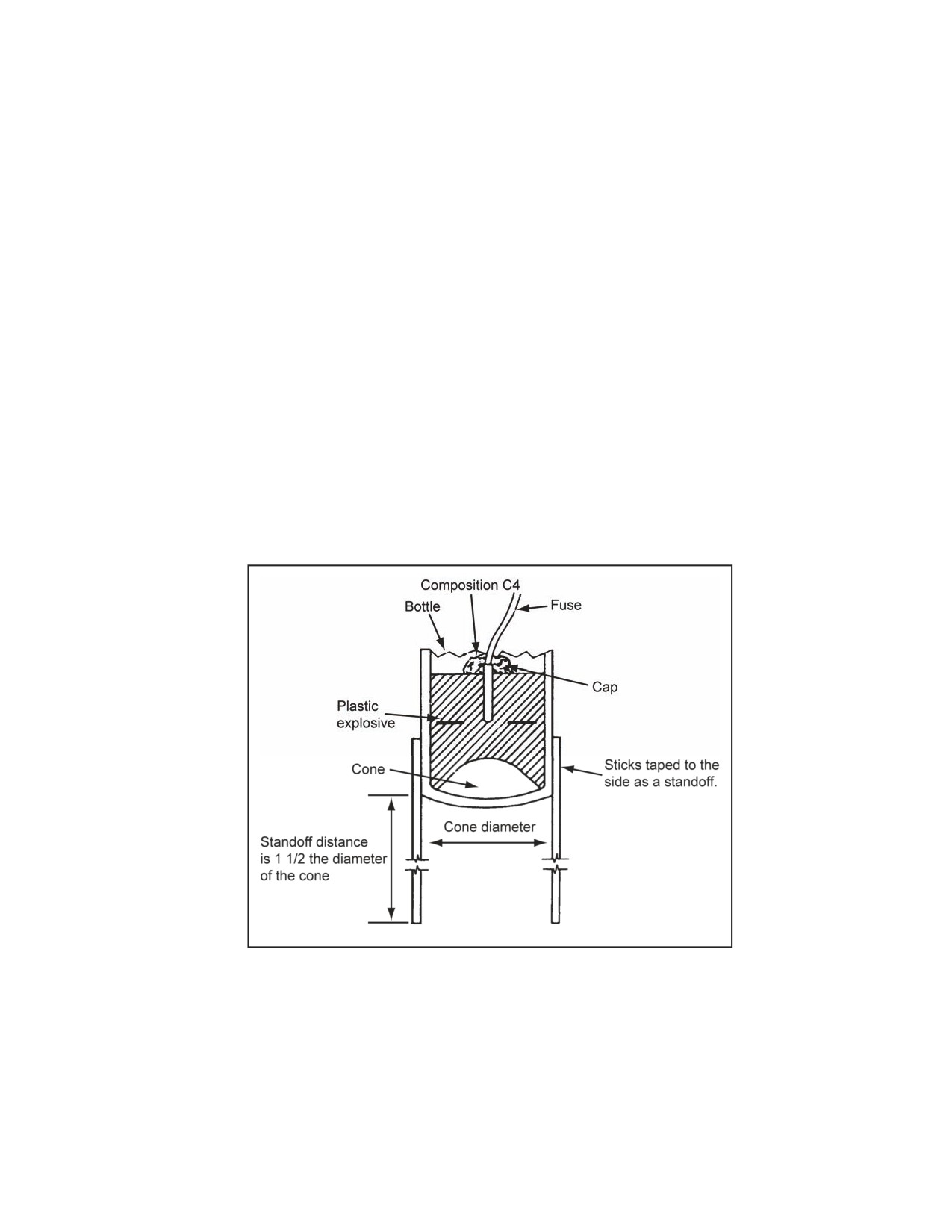
D-2. A shaped charge (Figure D-1) can be improvised. Because of the many variables (configuration,
explosive density, linear cavity density, and so forth), consistent results are impossible to obtain. Therefore,
experiment to determine the optimum standoff distances. Plastic explosive is best suited for this charge
type. However, dynamite and molten TNT can be effective expedients.
Figure D-1. Improvised Shaped Charge
FABRICATION
D-3. For a shaped charge, a container should be obtained. Both ends of the container should be removed.
Almost any kind of container will work (cans, jars, bottles, or drinking glasses). Some containers come
equipped with built-in cavity liners, such as champagne or cognac bottles with the stems removed. With the
ends removed, the container is ready for a cavity liner and explosive. Optimum shaped-charge
characteristics include the following:
11 July 2007
FM 3-34.214
D-1
Appendix D
Cavity liner. A cone-shaped cavity liner should be made for the container from copper, tin, zinc,
or glass. Funnels or bottles with a cone in the bottom (champagne or cognac bottles) are
excellent. However, if material is not available for a cavity liner, make a workable, but less
effective shaped charge by cutting a cone-shaped cavity in a block of explosive.
Cavity angle. For most high-explosive antitank (HEAT) ammunition, the cavity angle is 42° to
45°. Expedient charges will work with cavity angles between 30° and 60°.
Explosive height (in the container). The explosive height is two times the cone height,
measured from the base of the cone to the top of the explosive. Being careful not to alter the
cavity angle of the cone, press the explosive into the container. The explosive should be tightly
packed and free of any air pockets.
Standoff distance. The normal standoff distance is 1 1/2 the diameter of the cone. Standoff
sticks are used to achieve this.
Detonation point. The exact top center of the charge is the detonation point. If any part of the
blasting cap is exposed or extends above the charge, cover the blasting cap with a small quantity
of composition C4.
Note. Remove the narrow neck of a bottle or the stem of a glass by wrapping it with a piece of
soft, absorbent twine or by soaking the string in gasoline and lighting it. Place two bands of
adhesive tape, one on each side of the twine, to hold the twine firmly in place. Turn the bottle or
stem continuously with the neck up to heat the glass uniformly. Submerge the neck of the bottle
in water, and tap it against some object to break it off after the twine or plastic has burned. Tape
the sharp edge of the bottle to prevent cutting your hands while tamping the explosive in place.
A narrow band of plastic explosive placed around the neck of the bottle and burned, gives the
same results as string or twine. Do not immerse the bottle in water before the plastic explosive
has completely burned, or it may detonate.
PLATTER CHARGE
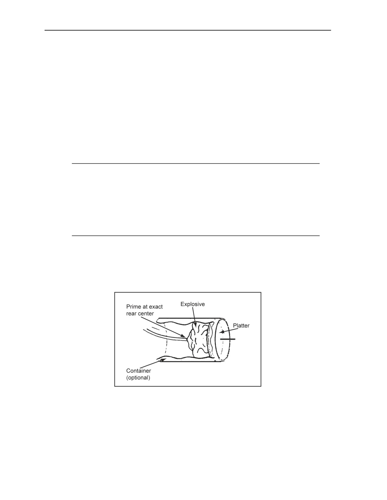
D-4. The platter charge uses the Miznay-Shardin effect. It turns a metal plate into a powerful, blunt-nosed
projectile (Figure D-2). The platter charge can be used in situations requiring shaped charges or as a
penetrator for demolition missions. If available, use a round, steel platter. However, a square platter will
also work.
Figure D-2. Platter Charge
CHARGE SIZE
D-5. A quantity of explosive equal to the weight of the platter should be used. The platter should weigh 2
to 6 pounds.
D-2
FM 3-34.214
11 July 2007
Expedient Demolitions
FABRICATION
D-6. The explosive should be uniformly packed behind the platter. A container is not necessary if the
explosive will remain firmly against the platter without a container. Tape is an acceptable anchoring
material. At the rear center, prime the charge. If any part of the blasting cap is exposed, cover the blasting
cap with a small quantity of composition C4.
D-7. If available, use a gutted M60 fuse igniter as an expedient aiming device, and aim the charge at the
direct center of a target. The explosive should be on the side of the platter opposite the target. With
practice, a 55-gallon drum or a relatively small target can be hit at 25 yards about 90 percent of the time
with a platter charge.
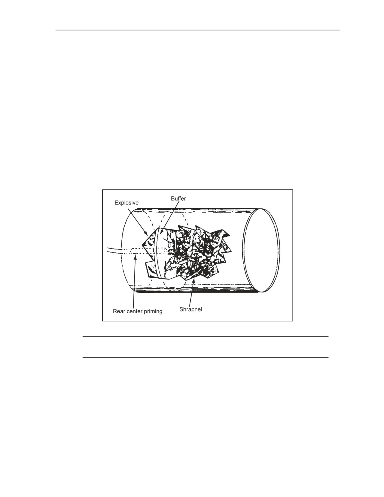
GRAPESHOT CHARGE
D-8. The grapeshot charge consists of a container (an ammunition can or a number 10 can), projectiles
(nails, bolts, small pieces of scrap metal, or rocks), buffer material (soil, leaves, felt, cloth, cardboard, or
wood), a charge (plastic explosive like composition C4), and a blasting cap or detonating cord. This charge
should be used when conventional claymore-type firing devices are not available. Assemble these
components as shown in Figure D-3. A quantity of explosive equal to 1/4 the projectile weight should be
used.
Figure D-3. Grapeshot Charge
Note. The United Nations Convention on Certain Conventional Weapons (CCW) mandates that
all fragment munitions produce fragments that are visible by an X ray (such as metal or rock).
D-9. In the center of the bottom of the container, make a hole large enough to accept a blasting cap or a
detonating cord knot. The components are placed in the container as follows:
Step 1. Explosive. Place the plastic explosive uniformly in the bottom of the container. Remove
all voids or air spaces by pressing the composition C4 into the container using a nonsparking
instrument.
Step 2. Buffer. Place 2 inches of buffer material directly on top of the explosive.
Step 3. Projectiles. Place the projectiles on top of the buffer material. Place a covering over the
projectiles to prevent them from spilling out when handling the charge.
D-10. In the plastic explosive charge, make a cap well through the hole in the bottom of the container, and
insert the blasting cap of the initiating set. If any part of the blasting cap is exposed, cover it with a small
quantity of composition C4. From about 100 feet, aim the charge at the center of the target.
11 July 2007
FM 3-34.214
D-3

Appendix D
DUST-INITIATOR CHARGE
D-11. Dust-initiator charges use small quantities of explosives with larger amounts of powdered materials
(dust or cover) to destroy thin-walled, wooden buildings or railroad boxcars. These charges work best in an
enclosed area with few windows. At detonation, the dust or cover is distributed in the air within the target
and ignited by an explosive-incendiary charge. The dust-initiator charge consists of an explosive (mixed
with equal parts of incendiary mix) and a cover of finely divided organic material. The charge can be
detonated by attaching initiating sets to the detonating cord.
CHARGE COMPUTATIONS
D-12. The charges and cover size for the charge computations are as follows:
Charge size. One pound of explosive-incendiary mixture will effectively detonate up to
40 pounds of cover. To make a 1-pound explosive-incendiary mixture, combine 1/2 pound of
crushed TNT or composition C3 and 1/2 pound of incendiary mix (two parts of aluminum
powder or magnesium powder and three parts of ferric oxide). Do not use composition C4,
because the explosive component in composition C4 will not combine properly with the
incendiary mixture.
Cover (dust) size. Use 3 to 5 pounds of cover for each 1,000 cubic feet of target (3 pounds for
enclosed buildings, and 5 pounds for partially enclosed buildings). The cover can consist of coal
dust, cocoa, powdered coffee, confectioners’ sugar, tapioca, wheat flour, cornstarch, hard rubber
dust, aluminum powder, magnesium powder, powdered soap, or a volatile fuel, such as gasoline.
FABRICATION
D-13. The TNT explosive is placed in a canvas bag and crushed into a powder with a wooden mallet. In the
same bag that contains the crushed explosive, an equal amount of incendiary mixture is added and mixed
thoroughly. This explosive incendiary charge is primed with a detonating cord knot. The primed charge is
placed in the center of the target. The cover is then poured or placed on top of the primed charge to form a
pyramid. When using gasoline as the cover, no more than 3 gallons should be used, since greater quantities
will not evenly disperse in the air and will give poor results.
IMPROVISED CRATERING CHARGE
D-14. This charge is used to supplement the 40-pound cratering charge or as an improvised cratering
charge when 40-pound cratering charges are not available. It consists of a mixture of ammonium-nitrate
fertilizer, (at least 33.33 percent nitrogen) and diesel fuel, motor oil, or gasoline. The ratio of fertilizer and
fuel is 25 pounds to 1 quart. The fertilizer must not be damp. From the mixture, almost any size of
improvised charge can be fabricated. Proceed as shown in the following steps:
Step 1. Measure the fertilizer and fuel for the size of charge required.
Step 2. Add the fuel to the fertilizer and mix thoroughly.
Step 3. Allow the fuel to soak into the fertilizer for 1 hour.
Step 4. Place half of the ammonium-nitrate charge in the borehole. Then, place two 1-pound
primed blocks of explosives in the borehole, and add the remainder of the ammonium-nitrate
charge. Never leave the charge in the borehole for a long period, since the charge will
accumulate moisture, reducing its effectiveness.
Note. Boreholes should receive 10 pounds of explosives for every foot of depth and must be
dual-primed.
Detonate the charge.
D-4
FM 3-34.214
11 July 2007
Expedient Demolitions
IMPROVISED BOREHOLE METHOD (DETONATING CORD WICK)
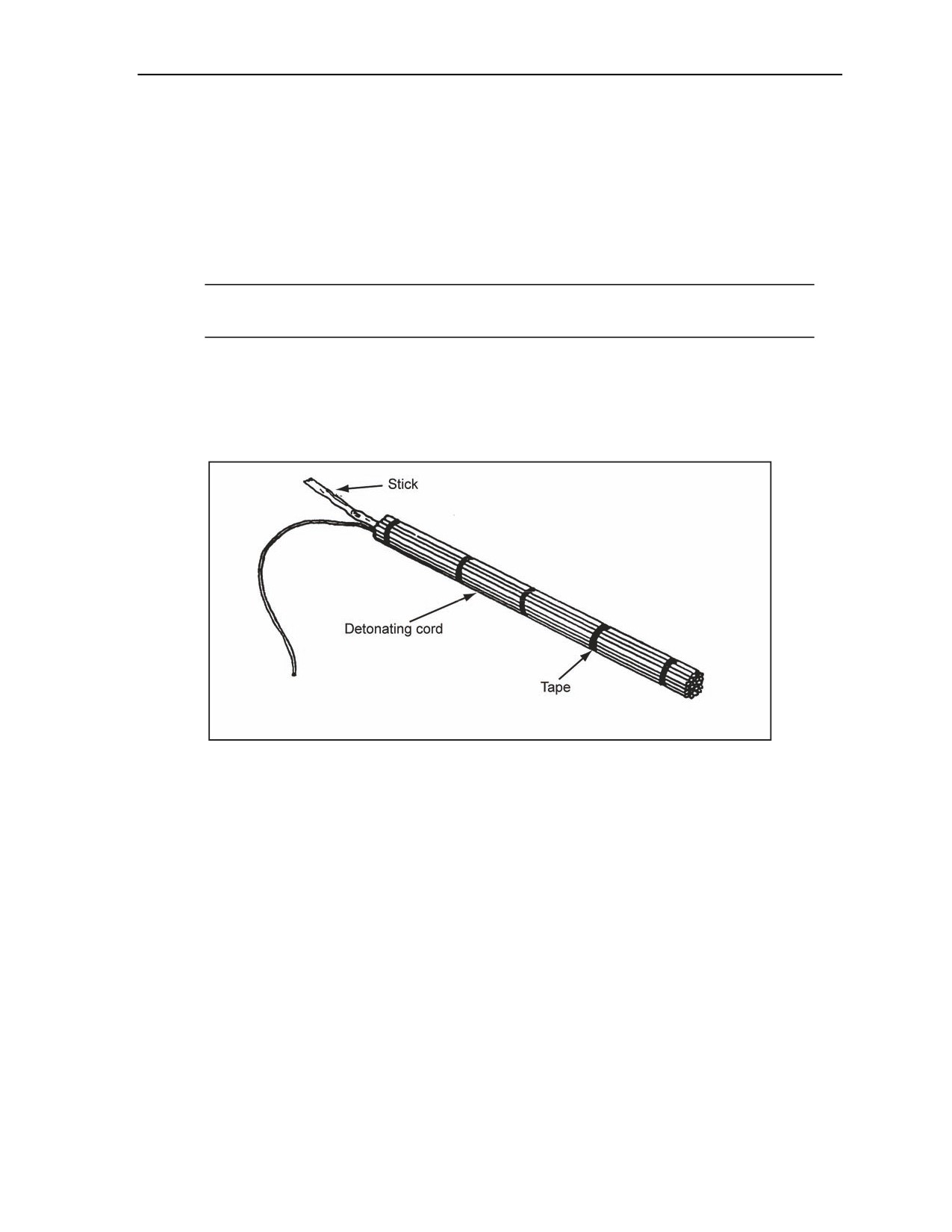
D-15. The detonating cord wick (Figure D-4) is used to enlarge boreholes in the soil. The best results are
obtained in hard soil. The following procedures should be used:
Tape together several strands of detonating cord 5 to 6 feet long (generally, one strand enlarges
the diameter of the hole by about 1 inch). Tape or tie the strands together into a wick for
optimum results.
Make a hole by driving a steel rod about 2 inches in diameter into the ground to the depth
required.
Note. According to the rule of thumb, a hole 10 inches in diameter holds 10 strands of
detonating cord.
Place the detonating cord wick into the hole using an inserting rod or some other field expedient.
Ensure that the strands are extended the full length of the hole.
Fire the cord either electrically or nonelectrically. Fire an unlimited number of wicks at one time
by connecting them with the detonating cord ring main or line main. Blow out excess gases and
inspect the hole for excessive heat if placing successive charges in the holes.
Figure D-4. Detonating Cord Wick
AMMONIUM-NITRATE SATCHEL CHARGE
D-16. Although a satchel charge is excellent, it is most suitable for cratering. A more manageable charge
may be used by mixing ammonium-nitrate fertilizer with melted wax instead of oil. The mixing ratio is
4 pounds of fertilizer to 1 pound of wax. The primer should be set in place before the mixture hardens.
PREPARATION
D-17. The following steps are used to prepare a ammonium-nitrate satchel charge:
Step 1. Melt the wax in a container.
Step 2. Stir in the ammonium-nitrate pellets, ensuring that the wax is hot while mixing. Before
the mixture hardens, add a 1/2-pound block of explosive primed with detonating cord.
Step 3. Ensure that the primed charge is in the center of the mixture and that there is enough
detonating cord available to attach the initiating sets.
Step 4. Pour the mixture into a container. Add shrapnel material to the mixture, if desired, or
attach on the outside of the container to give a shrapnel effect.
Step 5. Detonate the charge by attaching initiating sets to the detonating cord coming from the
satchel charge.
11 July 2007
FM 3-34.214
D-5
Appendix D
USE
D-18. Because the wax and fertilizer may be molded into almost any size or shape, it may be applied to a
large number of demolition projects with satisfactory results.
EXPEDIENT FLAME FOUGASSE
D-19. The expedient flame fougasse is used in defensive or offensive operations for its incendiary,
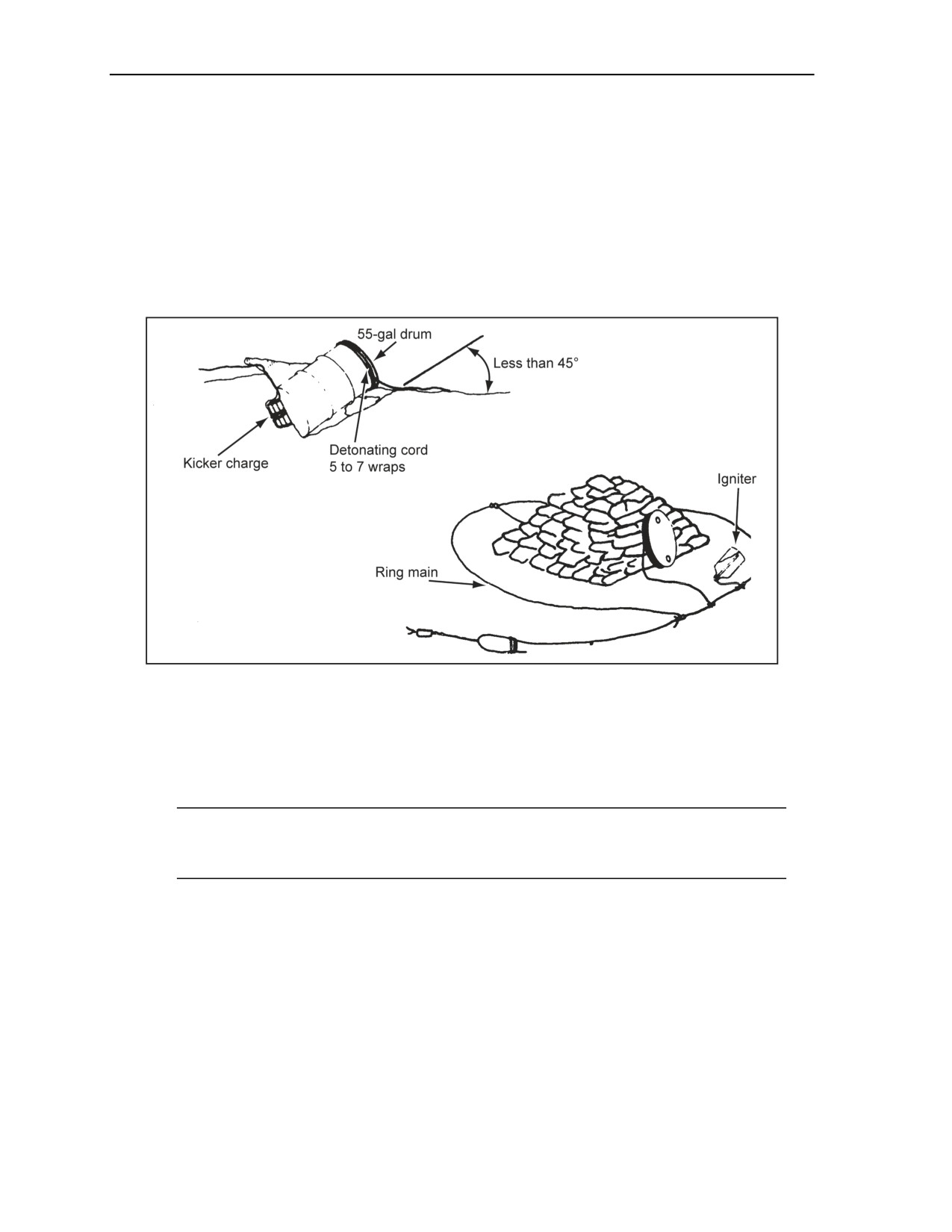
illuminating, and signaling effects. The charge consists of a 55-gallon drum of thickened fuel, a kicker
charge, and detonating cord (Figure D-5). A 55-gallon drum containing a fougasse mixture is effective for a
controlled-direction burst.
Figure D-5. Expedient Flame Fougasse
PREPARATION
D-20. The following steps are used to prepare a flame fougasse:
Step 1. Make the fougasse mixture by mixing 3 ounces of M4 thickening compound per gallon
of gasoline or jet petroleum 8 fuel.
Note. Depending on the temperature, the mixture may take from 15 minutes to several hours to
thicken to the desired viscosity (resembling applesauce or runny gelatin). For a 55-gallon drum,
vigorously mix 150 ounces of M4 thickening compound with 50 gallons of gasoline or JP 8 fuel.
Step 2. Dig an angled trench for the 55-gallon drum that will allow the best coverage and
dispersion of the flame fougasse. Do not build the trench steeper than 45°. Make a small cutout
area in the back of the trench for the kicker charge (2 pounds of TNT or 1 block of composition
C4).
Step 3. Prime the kicker charge with detonating cord, leaving 6 to 10 feet of detonating cord free
to tie into a ring main.
Step 4. Wrap the top end of the 55-gallon drum with 5 to 7 wraps of detonating cord, leaving 6
to 10 feet of the detonating cord free to tie into a ring main.
Step 5. Lay the drum in the trench, and place the kicker charge in the small cutout. Push the
drum against the back of the trench so that the kicker charge seats firmly against the bottom of
the drum. (It may be necessary to tamp the soil around the charge to center the kicker charge
properly against the bottom of the drum.) Ensure that the running ends of detonating cord for the
D-6
FM 3-34.214
11 July 2007

Expedient Demolitions
kicker charge and drum top extend from the trench. Avoid kinks or sharp bends in the detonating
cord.
Step 6. Lay out a ring main of detonating cord around the 55-gallon drum, and tie the detonating
cord from the kicker charge and wraps to the ring main.
Step 7. Cover the entire 55-gallon drum with a minimum of 3 feet of tamped soil, leaving the
front of the drum exposed or uncovered.
Step 8. Use a length of detonating cord and tape one end under the spoon handle of an igniter
trip flare (M49). Tape the spoon handle down securely, attach the trip flare to a stake, and
position the stake 3 to 4 feet in front of the drum. Attach the free end of the detonating cord that
is secured to the trip flare to the ring main. During combat, a white phosphorous (WP) grenade
(M34) will work in place of the trip flare. Do the following if trip flares are not available:
Take a 2-liter plastic bottle, and fill it half full with raw gasoline or JP 8 (unthickened).
Punch a hole in the cap of the bottle. Thread one end of a detonating cord through the hole.
Tie a single overhand knot in the detonating cord to prevent it from being pulled back out
of the cap.
Place the detonating cord with the single overhand knot inside the bottle. Secure the cap
onto the bottle.
Take the opposite end of the detonating cord, and attach it to the ring main.
Step 9. Attach initiating sets to the ring main or junction box.
FUNCTION
D-21. When initiated, the ring main initiates the detonating cord to the trip flare, the drum top, and the
kicker charge. The wraps cut the top of the drum off, the kicker charge propels the thickened fuel outward,
and the trip flare ignites the thickened fuel as it travels downrange. The result is a flash of flame that
spreads downrange for about 100 meters.
ALTERNATE EXPEDIENT FLAME FOUGASSE (USING STEEL WOOL)
D-22. Steel wool can be used to ignite the thickened fuel if fuel igniters or trip flares are not available. The
same amount of explosives is used for a kicker charge (2 pounds of TNT or 1 block of composition C4).
The explosives are primed with detonating cord. A buffer material is attached (such as cardboard around
the kicker charge) and secured with tape. Steel wool is attached to the buffer material so that it covers the
entire width of the kicker charge. The steel wool will ignite the fuel in the drum once the kicker charge is
propelled through the back section. The steel wool must be in contact with the back section of the drum.
The result will be the same as with the fuel igniter or trip flare.
IMPROVISED BANGALORE TORPEDO
D-23. The improvised bangalore torpedo is used to defeat wire obstacles. The following steps are used to
prepare an improvised bangalore:
Step 1. Separate the packaging material from the composition C4 (M112). Place it in the
concave portion of two U-shaped pickets that are not bent or damaged.
Step 2. Mold the composition C4 explosive, using a nonsparking tool, into the concave position
that runs the entire length of the U-shaped pickets.
Step 3. Place a line of detonating cord (after tamping the composition C4) on top of the
composition C4 of one of the pickets, and make a single overhand knot every 6 to 8 inches.
Ensure that the detonating cord runs several feet past the U-shaped picket length so that it can be
tied into a firing system.
Step 4. Place the other U-shaped picket (tamped with composition C4) onto the picket with the
detonating cord. Ensure that the composition C4 explosive from each picket is touching and that
the detonating cord is in the middle.
Step 5. Secure the two U-shaped pickets together with tape or wire.
11 July 2007
FM 3-34.214
D-7
Appendix D
EXPEDIENT BRANCHLINE CONNECTIONS
GREGORY KNOT
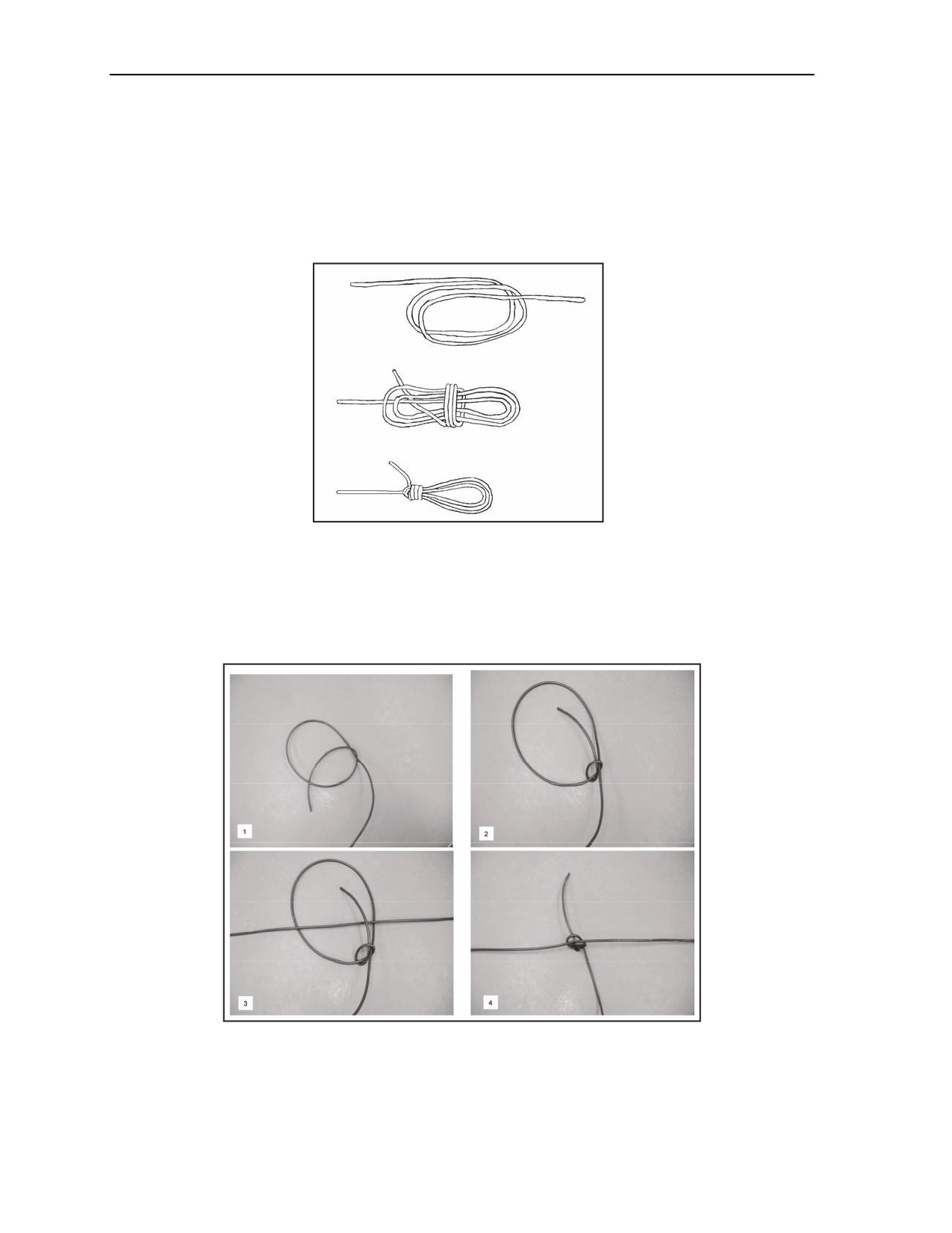
D-24. The Gregory knot (Figure D-6) is a detonating cord knot tied at the end of a branchline to connect the
branchline to a firing system. The Gregory knot saves time on a target when tied before arriving at the
mission site. This knot does not take the place of the girth hitch with an extra turn or detonating cord clips.
Step 1
Step 2
Step 3
Figure D-6. Gregory Knot
SCANMAN KNOT
D-25. The scanman knot (Figure D-7) is a detonating cord knot tied at the end of a branchline to connect
the branchline to a firing system. The scanman knot saves time on a target when tied before arriving at the
mission site. This knot does not take the place of the girth hitch with an extra turn or detonating cord clips.
Figure D-7. Scanman Knot
D-8
FM 3-34.214
11 July 2007

Appendix E
Power Requirements for Series Firing Circuits
Electric blasting caps are connected in a series and fired with an electric power
source (blasting machine). A series circuit provides a single path for the electrical
current that flows from one firing wire through each blasting cap to the next blasting
cap and back to the other firing wire. A series circuit should not contain more than
50 blasting caps. Connecting more than 50 blasting caps in a series circuit increases
the chances of breaks in the firing line or cap leads.
OHM’S LAW
E-1. Ohm’s law defines the amount of voltage necessary to detonate the blasting caps. The required
voltage for a firing circuit is determined as follows:
E = IR
where—
E
= electric potential or voltage (in volts)
I
= current (in amperes)
R
= resistance (in ohms)
ELECTRIC-POWER FORMULA
E-2. The amount of electric power (watts) necessary to detonate blasting caps is determined as follows:
W = I2R
where—
W = electrical power (in watts)
I
= current (in amperes)
R
= resistance (in ohms)
ELECTRIC BLASTING CAPS
E-3. Military electric blasting caps connected in a series require at least 1.5 amperes to fire, regardless of
the number of caps in the series. The resistance of a military electric blasting cap is 2 ohms.
CIRCUIT RESISTANCE
E-4. The power source should be adequate to fire all charges connected to the circuit. Firing wire and
blasting caps contribute to the total resistance in the circuit. The amount of resistance is determined by
combining the individual resistances of the blasting caps and wires. The resistance of the wire depends on
the size and length of the wire. Table E-1, page E-2, gives the resistance per 1,000 foot of various sizes of
copper wire.
11 July 2007
FM 3-34.214
E-1

Appendix E
Table E-1. Resistance of Copper Wire
Wire Characteristics
AWG (B&S) Gauge
Resistance per
Diameter (in)
Weight (lb/ft)
Number
1,000 ft (ohms)
2
3/10
5.0
0.2
4
1/4
7.9
0.3
6
1/6
12.6
0.4
8
1/8
20.0
0.6
10
1/10
31.8
1.0
12
1/12
50.0
1.6
14
1/16
80.0
2.5
16
1/20
128.0
4.0
18
1/25
203.0
6.4
20
1/30
323.0
10.2
Note. For resistance, the ratings are for single-strand wire. Since blasting wire usually
comes in double strands, use half its length to compute total resistance.
SERIES CIRCUIT CALCULATIONS
E-5. Calculations are completed for any series circuit involved in determining the amount of current
(amperes), voltage (volts), and power (watts) needed to fire the circuit. The following procedures are
applied:
Current. Ensure that the current required for a series circuit of electric blasting caps is
1.5 amperes, regardless of the number of blasting caps in the circuit.
Resistance. Determine the resistance in the circuit as explained in paragraph E-4.
Voltage. Determine the required voltage for the circuit using the formula in paragraph E-1.
Power. Determine the required power for the circuit using the formula in paragraph E-2.
E-6. The current, voltage, and power required to detonate a 20-cap series circuit consisting of special
electric blasting caps and 500 feet of standard, 2-conductor, 18-gauge firing wire is determined by using the
following procedure:
Current. Ensure that the amount of current required to detonate this circuit is 1.5 amperes.
Resistance. Use the information below to obtain the resistance.
Caps. 2.0 ohms (20 caps) = 40.0 ohms.
Wire. 500 feet (2 strands) = 1,000 feet = 6.4 ohms (Table E-1).
Total resistance. 46.4 ohms.
Note. Number 18 wire consists of two strands. The example specifies a 500-foot piece of wire,
so use 1,000 feet as the total wire length for determining resistance (500 x 2 = 1,000).
Voltage. Use the formula below to obtain the voltage.
E = IR = 1.5(46.4) = 69.6 volts
E-2
FM 3-34.214
11 July 2007

Power Requirements for Series Firing Circuits
Power. Use the formula below to obtain the power.
W = I2(R) = 1.52(46.4) = 104.4 watts
VOLTAGE DROP
E-7. Ohm’s law allows you to determine the amount of voltage required (voltage drop) for a blasting
circuit. In practice, the voltage drop should never exceed 90 percent of the available voltage. If it does,
decrease the resistance or increase the voltage in the circuit to ensure that proper detonation occurs.
BLASTING MACHINES
E-8. The nameplate on power sources normally states the amperage and the voltage ratings. Before using
any power source, determine whether it is suitable for the firing circuit. Generally, determine the adequacy
of a power source by consulting Table E-2. This table lists the sizes of circuits that power sources can
support. The capabilities of the power source must be determined from the nameplate. The following steps
are followed:
Step 1. Multiply the voltage rating of the power source by 90 percent to get an adjusted voltage
rating.
Step 2. Divide the adjusted voltage rating by the amperage rating (1.5 amperes) of the circuit.
Note. At this point, you have the maximum allowable resistance in the circuit in ohms.
Step 3. Determine the total resistance of the firing wire (Table E-1).
Step 4. Subtract the resistance of the wire from the maximum allowable circuit resistance
(step 2) to determine the maximum allowable resistance of the blasting caps in the circuit.
Step 5. Determine the maximum number of blasting caps the circuit will support by dividing the
allowable resistance for caps (step 4) by the resistance in one cap (2 ohms).
Table E-2. Power Source Capabilities
Circuit Size (Series)
Power Source
10-cap
30-cap
50-cap
Blasting machine, 10 cap
X
—
—
Blasting machine, 30 cap
X
X
—
Blasting machine, 50 cap
X
X
X
Generator, 1.5 kw, portable (115 volts, 13.5 amperes)
X
X
—
Generator, 3 kw, portable (115 volts, 26 amperes)
X
X
—
Generator, 5 kw, portable (115 volts, 43.5 amperes)
X
X
—
Generator, 3 kw, portable (220 volts, 13.5 amperes)
X
X
X
Generator, 5 kw, portable (220 volts, 22.5 amperes)
X
X
X
E-9. The maximum number of electric blasting caps allowed in a series circuit fired by a 220-volt,
13.5-ampere generator and 250 feet of double-strand, 20-gauge wire (a total of 500 feet of wire) is
determined as follows:
Maximum allowable resistance (paragraph E-8, steps 1 and 2).
0.90 (200 volts)
= 120 ohms
1.5 amperes
11 July 2007
FM 3-34.214
E-3

Appendix E
Total resistance of the firing wire (Table E-1, page E-2).
10.2 ohms (500 feet)
= 5.1 ohms
1,000
Maximum allowable resistance of the blasting caps (paragraph E-8).
120 ohms - 5.1 ohms = 126.9 ohms
Maximum number of blasting caps.
126.9 ohms
= 63.45 caps (round down to 63 caps)
2 ohms
BATTERIES AND DRY CELLS
E-10. See paragraph E-9. The procedure in paragraph E-9 is used to determine the size of a circuit
supported by a battery or dry cell.
E-4
FM 3-34.214
11 July 2007

Appendix F
Example Calculations
This appendix contains examples of charge, demolition, and attack calculations that
are discussed in Chapters 3 and 4. Use TNT in the 1-pound package and use 20 cubic
inches for the volume of composition C4 when calculating the problems that follow.
For examples of charge calculations, refer to Figures F-1 through F-11, pages F-1
through F-9. For examples of demolition calculations, see Figure F-12, page F-10.
For examples of attack calculations, see Figures F-13 through F-15, pages F-11
through F-13.
CHARGE CALCULATIONS
Problem. Using the internal timber cutting charge, determine the quantity of composition C4 required to cut a
30-inch diameter tree.
Obtain the critical dimensions.
Step 1
D = 30 inches
Calculate the TNT or use the rule of thumb.
2
2
D
30
900
Step 2
P =
=
=
=
3.6 pounds of TNT
250
250
250
Note. P = .004D2
Divide by the RE factor, if required.
Step 3
P
3.6
=2.68 pounds of composition C4
RE
= 1.34
Divide by the package weight or volume, and round UP to the next whole package.
Step 4
P
2.68
=
2.14, round up to 3 packages of compositio n C4
Package weight
= 1.25
Calculate the number of charges.
Step 5
One tree = One charge
Note. You must split the charge between the two boreholes because the tree is larger than 18 inches in diameter. See
Chapter 3, Section II.
Calculate the total amount of explosives.
Step 6
Step 4 x Step 5 = Total packages = 3 x 1 = 3 packages of composition C4
Solution. To cut a 30-inch diameter tree using an internal timber-cutting charge, three packages of
composition C4 is needed and is placed in two boreholes. See Figure 3-2, page 3-5, for charge placement.
Figure F-1. Timber-Cutting Charge Calculation (Internal)
11 July 2007
FM 3-34.214
F-1

Appendix F
Problem. Using the external timber cutting charge formula, determine the quantity of TNT required to cut a
30-inch diameter tree.
Obtain the critical dimensions.
Step 1
D = 30 inches
Calculate the TNT or use the rule of thumb.
2
2
D
30
900
Step 2
P =
=
=
=22.5 pounds of TNT
40
40
40
Note. P = .025D2
Divide by the RE factor, if required.
Step 3
P
22.5
=
=
22.5 pounds of TNT
RE
1
Divide by package weight or volume, and round UP to the next whole package.
Step 4
P
22.5
=
=
22.5 packages of TNT; round up to 23 packages of TNT
Package weight
1
Calculate the number of charges.
Step 5
One tree = One charge
Calculate the total amount of explosives.
Step 6
Step 4 x Step 5 = Total packages = 23 x 1 = 23 packages of TNT
Solution. To cut a 30-inch diameter tree using an external timber charge, 23 packages of TNT is needed. See
Figure 3-3, page 3-6, for charge placement.
Figure F-2. Timber-Cutting Charge Calculation (External)
F-2
FM 3-34.214
11 July 2007
Example Calculations
3
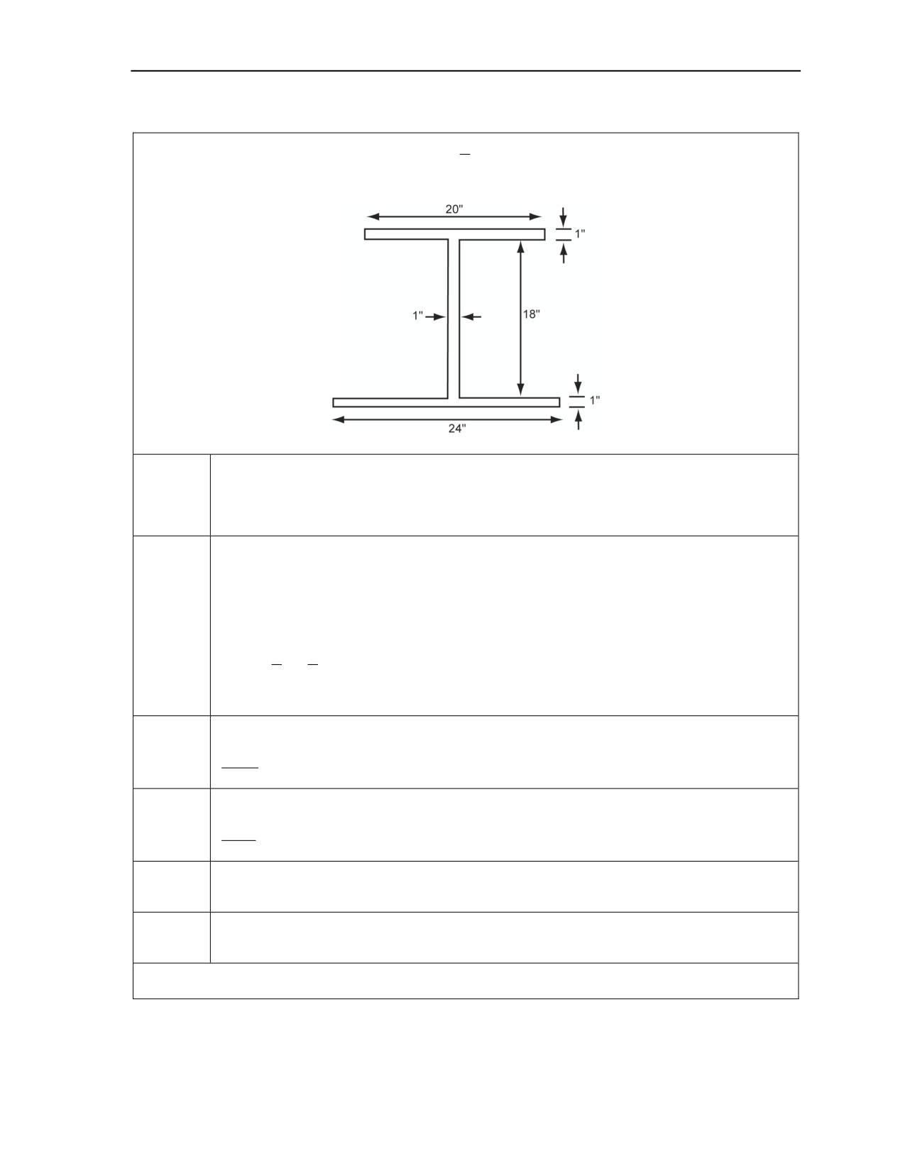
Problem. Using the steel-cutting charge formula,
P =
A
, determine the quantity of composition C4 required
8
to cut the two steel beams shown below.
Obtain the critical dimensions.
Step 1
a. Top flange: 20 x 1 = 20 square inches
b. Web: 18 x 1 = 18 square inches
c. Bottom flange: 24 x 1 = 24 square inches
Calculate the TNT or use the rule of thumb.
a. Top flange: 20 x 1 = 20 square inches
b. Web: 18 x 1 = 18 square inches
c. Bottom flange: 24 x 1 = 24 square inches
Step 2
d. Total square inches = 62 square inches (a + b + c)
3
3
P =
A
=
x
62
=
23.25 pounds of TNT
8
8
Note. P = 0.375A
Divide by the RE factor, if required.
Step 3
23.25
=17.35 pounds of composition C4
1.34
Divide by the package weight or volume, and round UP to the next whole package.
Step 4
17.35
=13.8; round up to 14 packages of composition C4
1.25
Calculate the number of charges.
Step 5
Two beams = Two charges
Calculate the total amount of explosives.
Step 6
Step 4 x Step 5 = Total packages = 14 x 2 = 28 packages of composition C4
Solution. To cut the two beams, 28 packages of composition C4 is needed. See Figure 3-7, page 3-10, for
charge placement.
Figure F-3. Steel-Cutting Charge Calculation
11 July 2007
FM 3-34.214
F-3
Appendix F
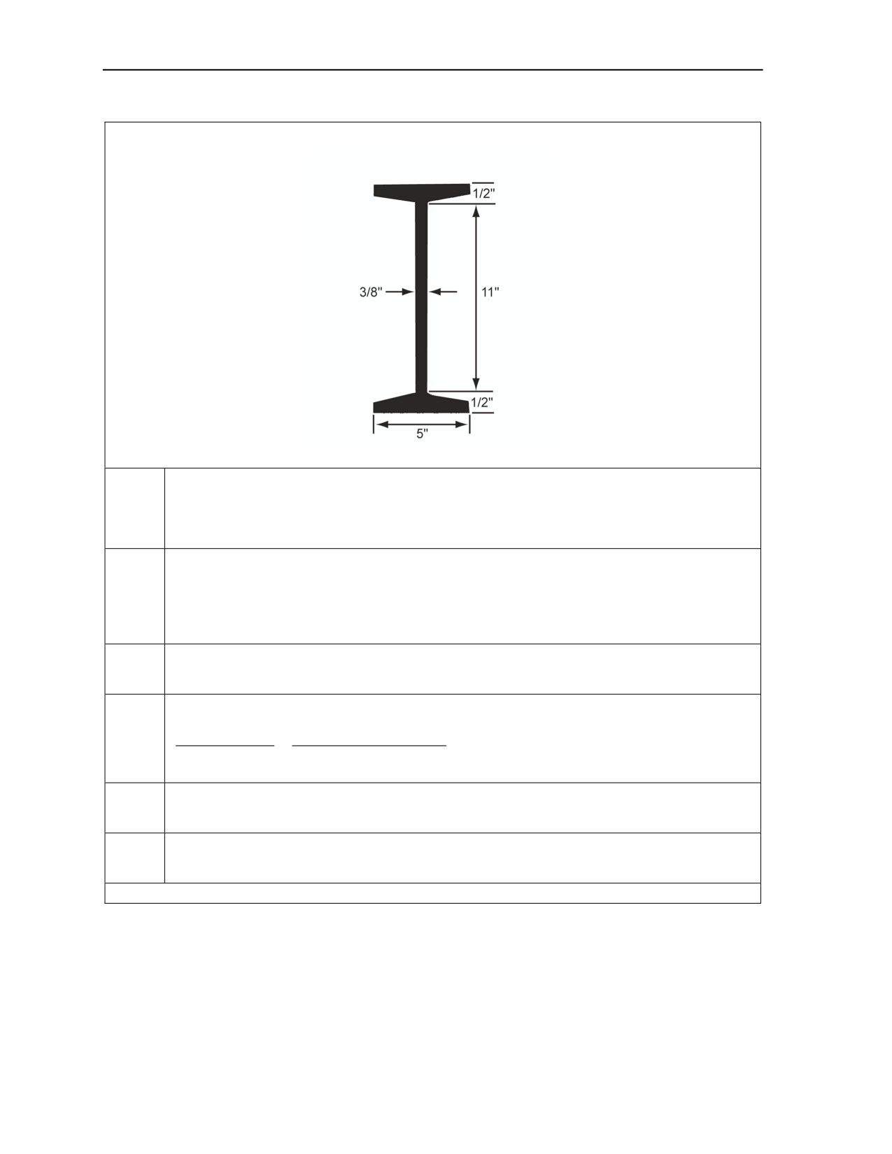
Problem. Using the hasty, steel-cutting formula and Table 3-4, page 3-12, determine the quantity of
composition C4 required to cut the steel beam shown below.
Obtain the critical dimensions.
Step 1
a. Top flange: 5 x 1/2 inches
b. Web: 11 x 3/8 inches
c. Bottom flange: 5 x 1/2 inches
Calculate the TNT or use the rule of thumb.
a. Top flange: 5 x 1/2 = 0.8 pounds from Table 3-4
Step 2
b. Web: 11 x 3/8 pounds = 1.3 pounds from Table 3-4
c. Bottom flange: 5 x 1/2 = 0.8 pounds from Table 3-4
d. Total = 2.9 pounds of composition C4 (a + b + c)
Divide by the RE factor, if required.
Step 3
Not required.
Divide by the package weight or volume, and round UP to the next whole package.
Step 4
P
2.9 lbs of compositio n C4
=
=
2.32; round up to 3 packages of compositio n C4
Package weight
1.25 package weight
Calculate the number of charges.
Step 5
One beam = One charge
Calculate the total amount of explosives.
Step 6
Step 4 x Step 5 = Total packages = 3 x 1 = 3 packages of composition C4
Solution. Three packages of composition C4 is needed. See Figure 3-7, page 3-10, for charge placement.
Figure F-4. Hasty, Steel-Cutting Charge Calculation
F-4
FM 3-34.214
11 July 2007
Example Calculations
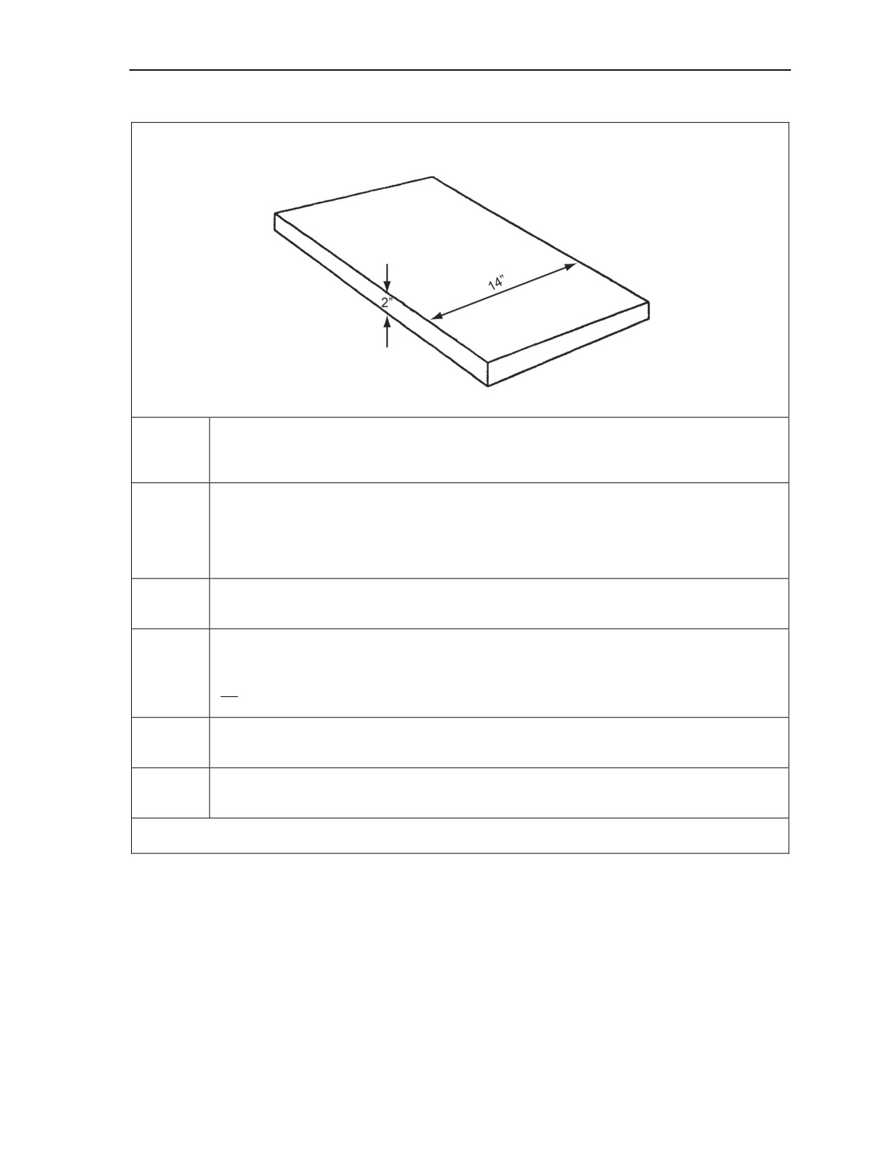
Problem. Using the steel-cutting charge calculation (steel plate), determine the quantity of composition C4
required to cut the steel plate shown below using a ribbon charge.
Obtain the critical dimensions.
Step 1
a. Cut length: 14 inches
b. Target thickness: 2 inches
Calculate the TNT or use the rule of thumb.
a. Thickness: 1/2 (target thickness) = 1 inch
Step 2
b. Width: 3 (charge thickness) = 3 inches
c. Length: cut length = 14 inches
Volume = T x W x L = 1 x 3 x 14 = 42 cubic inches
Divide by the RE factor, if required.
Step 3
Not required because only composition C4 or sheet explosives are used.
Divide by the package volume, and round UP to the next whole package.
M112 volume = 20 cubic inches
Step 4
42
=2.1
(round up to 3)
20
Calculate the total amount of charges.
Step 5
One plate = One charge
Calculate the total amount of explosives.
Step 6
Step 4 x Step 5 = Total packages = 3 x 1 = 3 packages of composition C4
Solution. To cut the steel plate, three packages of composition C4 is needed. See Figure 3-11, page 3-15, for
charge placement.
Figure F-5. Steel-Cutting Charge Calculation (Steel Plate)
11 July 2007
FM 3-34.214
F-5
Appendix F
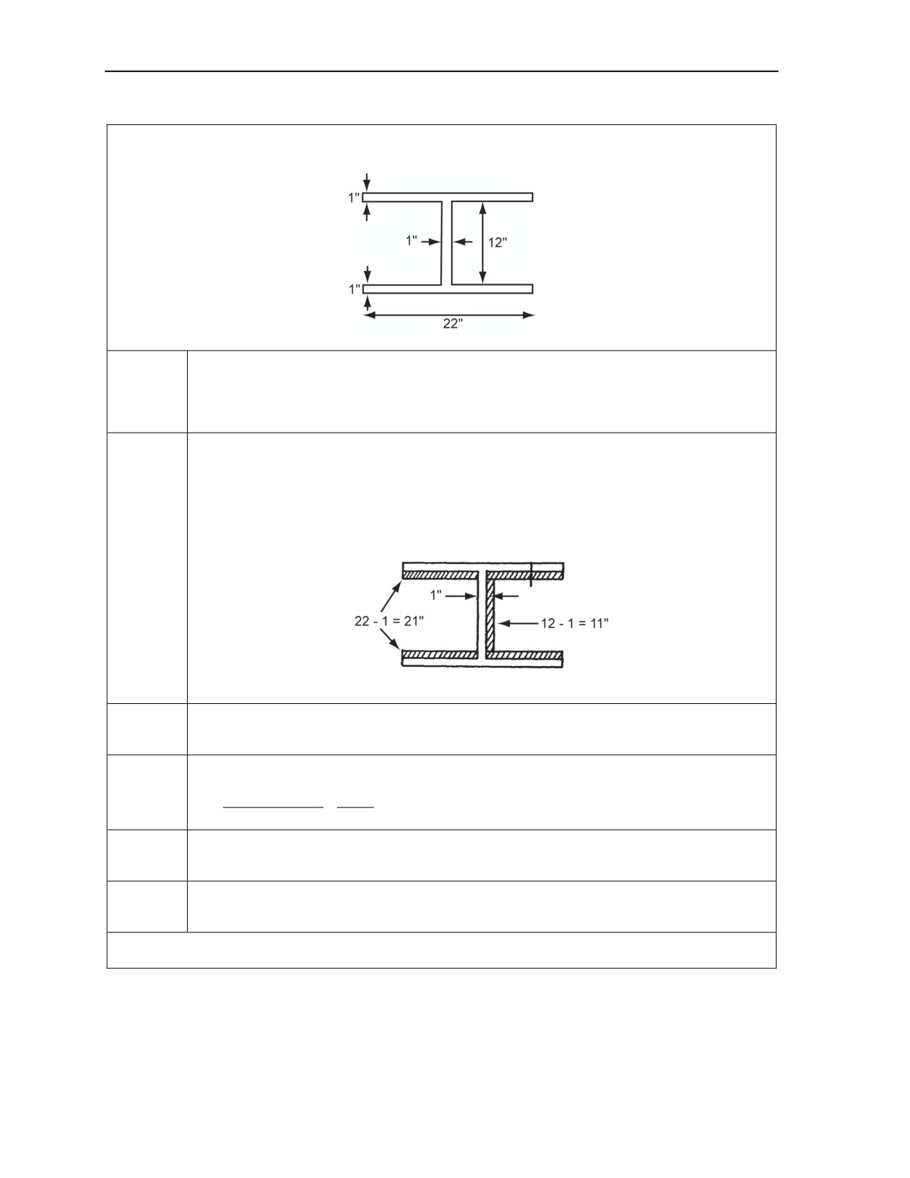
Problem. Using the steel-cutting charge calculation (I beam), determine the quantity of composition C4
required to cut the I beam shown below using a ribbon charge.
Obtain the critical dimensions.
Step 1
a. Top flange: 22 x 1 = 22 inches
b. Web: 12 x 1 = 12 inches
c. Bottom flange: 22 x 1 = 22 inches
Calculate the TNT or use the rule of thumb.
a. Thickness = 1/2 (target thickness) = 1/2 inches
b. Width = 3 (charge thickness) = 1 1/2 inches
c. Length = Cut length = 21 + 21 + 11 = 53 inches
Volume = T x W x L = 1/2 x 1 1/2 x 53 = 39.75 cubic inches of composition C4
Step 2
Divide by the RE factor, if required.
Step 3
Not required because only composition C4 or sheet explosives are used.
Divide by the package weight or volume, and round UP to the next whole package.
Step 4
Charge volume
39.75
N =
=
=1.98; round up to 2 packages of composition C4
Package volume
20
Calculate the number of charges.
Step 5
One I beam = One charge
Calculate the total amount of explosives.
Step 6
Step 4 x Step 5 = Total packages = 2 x 1 = 2 packages of composition C4
Solution. To cut the I beam, two packages of composition C4 as needed. See Figure 3-12, page 3-15, for
charge placement.
Figure F-6. Steel-Cutting Charge Calculation (I Beam)
F-6
FM 3-34.214
11 July 2007

Example Calculations
Problem. Using the steel-cutting charge calculation (steel bar), determine the quantity of composition C4
required to cut a 7-inch steel bar using a saddle charge.
Obtain the critical dimensions.
Step 1
a. Target diameter = 7 inches
b. Target circumference = 3.14 x 7 = 21.98 inches
Calculate the TNT or use the rule of thumb.
a. Thickness = 1.00 inch
Step 2
b. Base width = 1/2 (target circumference) = 10.99 inches
c. Long axis = target circumference = 21.98 inches
d. Total volume = 1/2 (base width) (long axis) = 120.78 cubic inches of explosive
Divide by RE factor, if required.
Step 3
Not required because only composition C4 or sheet explosives are used.
Divide by the package weight or volume, and round UP to the next whole package.
Step 4
Charge volume
153.75
N =
=
=
7.68; round up to 8 packages of composition C4
Package volume
20
Calculate the number of charges.
Step 5
One bar = One charge
Calculate the total amount of explosives.
Step 6
Step 4 x Step 5 = Total packages = 8 x 1 = 8 packages of composition C4
Solution. To cut the steel bar using a saddle charge, eight packages of composition C4 is needed. See
Figure 3-13, page 3-16, for charge placement.
Figure F-7. Steel-Cutting Charge Calculation (Steel Bar)
Problem. Using the steel-cutting charge calculation (high-carbon steel), determine the quantity of composition
C4 required to cut an 8-inch, high-carbon, steel bar using a diamond charge.
Obtain the critical dimensions.
Step 1
a. Target diameter: 8 inches
b. Target circumference: 3.14 x 8 = 25.12 inches
Determine the required charge dimensions.
a. Thickness: 1.00 inch
Step 2
b. Short axis: 1/2 (target circumference) = 12.56 inches
c. Long axis: target circumference = 25.12 inches
d. Total volume: 1/2 (thickness x long axis x short axis) = 157.7536 cubic inches
It is not necessary to determine the equivalent amount of composition C4 because this charge uses
Step 3
and is computed for plastic explosive (composition C4) or sheet explosive, not TNT.
Determine the number of required packages of composition C4.
Step 4
Charge volume
157.7536
N =
=
=
7.88768; round up to 8 packages of composition C4
Package volume
20
Calculate the number of charges.
Step 5
One bar = One charge
Calculate the total amount of explosives required.
Step 6
Step 4 x Step 5 = Total packages 8 x 1 = 8 packages of composition C4 is required
Solution. To cut one high-carbon steel bar, eight packages of composition C4 is needed. See Figure 3-14,
page 3-17, for charge placement.
Figure F-8. Steel-Cutting Charge Calculation (High-Carbon Steel)
11 July 2007
FM 3-34.214
F-7

Appendix F
Problem. Using the formula R3KC, determine the number of composition C4 packages required to breach a
reinforced-concrete pier, 5 feet thick and 30 feet wide. The charges will be elevated 5 feet and untamped.
Obtain the critical dimensions.
Step 1
a. Breaching radius (R): 5 feet
b. Pier width (W): 30 feet
Calculate the TNT or use the rule of thumb.
Step 2
P = R3KC = 53(0.63)1.8 = 141.75 pounds of TNT
Divide by the RE factor, if required.
Step 3
141.75
=105.78 pounds of composition C4
1.34
Divide by the package weight or volume, and round UP to the next whole package.
Step 4
Charge weight
105.78
N =
=
=84.62; round up to 85 packages of composition C4
Package weight
1.25
Calculate the number of charges.
Step 5
W
30
N =
=
=3 charges
2R
2(5)
Calculate the total amount of explosives.
Step 6
Step 4 x Step 5 = Total packages = 85 x 3 = 255 packages of composition C4
Solution. To breach the pier, 255 packages of composition C4 are needed. See Figure 3-16, page 3-22, for
charge placement.
Figure F-9. Breaching Charge Calculation (Reinforced Concrete Pier)
Problem. Using the counterforce charge calculation, determine the required amount of composition C4
needed to counterforce four concrete cubes 3 feet thick.
Obtain the critical dimensions.
Step 1
Target thickness = 3 feet
Calculate the TNT or use the rule of thumb.
Step 2
P = 1 1/2 pounds of composition C4 per foot of diameter
P = 1 1/2 x 3 = 4.5 pounds of composition C4
Divide by the RE factor, if required.
Step 3
Not required because only composition C4 or sheet explosives are used.
Divide by the package weight or volume, and round UP to the next whole package.
Step 4
Charge weight
4.5
N =
=
=
3.6; round up to 4 packages of composition C4
Package weight
1.25
Calculate the number of charges.
Step 5
Four cubes = Four charges
Calculate the total amount of explosives.
Step 6
Step 4 x Step 5 = Total packages = 4 x 4 = 16 packages of composition C4
Solution. To counterforce four cubes, 16 packages of composition C4 as needed. See Figure 3-17,
page 3-22, for charge placement.
Figure F-10. Counterforce Charge Calculation
F-8
FM 3-34.214
11 July 2007

Example Calculations
Problem. Using the cratering charge calculation, determine the quantity of cratering charges and composition
C4 required to create a deliberate crater 146 feet long.
Obtain the critical dimensions.
Step 1
Crater length (L) = 146 feet
Calculate the TNT or use the rule of thumb.
Step 2
a. 7-foot borehole = 80 pounds of explosive
b. 5-foot borehole = 40 pounds of explosive
Divide by the RE factor, if required.
Step 3
Not required.
Divide by the package weight or volume, and round UP to the next whole package.
Step 4
a. 7-foot borehole = 2 cratering charges and 2 packages of composition C4
b. 5-foot borehole = 1 cratering charge and 2 packages of composition C4
Calculate the number of charges.
Step 5
L -16
146 - 16
N =
+1=
+1=27 holes
5
5
27/2 = 13.5; round up to 14 for 7-foot holes and round down to 13 for 5-foot holes
Calculate the total amount of explosives.
a. 7-foot boreholes: 14 holes (2 cratering charges + 2 packages of composition C4) = 28
cratering charges + 28 packages of composition C4
Step 6
b. 5-foot boreholes: 13 holes (1 cratering charges + 2 packages of composition C4) = 13
cratering charges + 26 packages of composition C4
Total = 41 cratering charges and 54 packages of composition C4
Solution. To create a deliberate crater 146 feet long, 41 cratering charges and 54 packages of composition
C4 are needed. See Figure 3-19, page 3-25, for charge placement.
Figure F-11. Cratering Charge Calculation
11 July 2007
FM 3-34.214
F-9
Appendix F
DEMOLITION CALCULATIONS
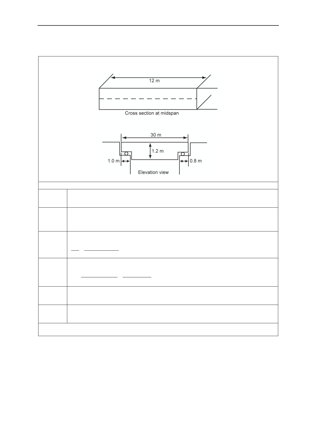
Problem. Using a concrete-stripping charge to destroy a simply supported, concrete-deck, top-support bridge
span. The diagram below shows the span dimensions (determine the quantity of composition C4 required).
Beam Calculations
Determine the amount of TNT required per meter.
Step 1
P = (3.3h + 0.5)3 3.3 = [3.3(1.2) + 0.5]3 3.33 = 295.42606488 pounds of TNT per meter
Determine the amount of explosive (TNT) per beam.
Step 2
P = (pounds TNT/meter) (bridge width, in meters)
P = 295.42606488 = 3545.11277856 pounds of TNT
Determine the equivalent amount of composition C4.
Step 3
P
3545.11277856
=
=2645.606551 pounds of composition C4
RE
1.34
Determine the required packages of composition C4 per beam.
Step 4
Charge weight
2645.606551
P
=
=
=2116.532408; round up to 2117 of composition C4
Package weight
1.25
Calculate the number of charges.
Step 5
One bridge = One charge
Calculate the total amount of explosives.
Step 6
Step 4 x Step 5 = Total packages = 2117 x 1 = 2117 packages of composition C4
Solution. To destroy this simply-supported concrete deck, top support bridge span, 2,098 packages of
composition C4 is needed.
Figure F-12. Concrete Stripping Charge Calculation
F-10
FM 3-34.214
11 July 2007
Example Calculations
ATTACK DEMOLITIONS
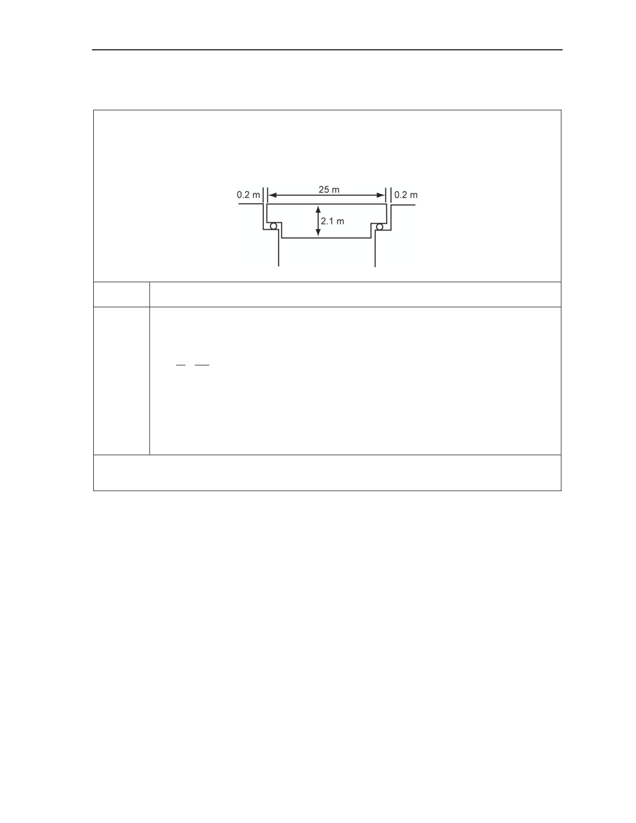
Problem. Using a bottom-attack bridge calculation, determine the attack method for demolishing a simply
supported, steel-beam deck bridge with bottom supports and the following measurements:
a. Length (L): 25 meters
b. Height (H): 2.1 meters
c. End clearance (E): 0.4 meters
Refer to Appendix H. Table H-1, page H-1, lists the bottom attack method for this bridge,
Step 1
provided that the actual end clearance (E) is greater than ER.
Perform the calculation to determine whether E is greater than ER.
a. Determine the height-to-length ratio (H/L).
H
2.1
=
=0.084
L
25
Step 2
b. Find the corresponding E/L value (Table H-1). Since 0.084 is not found on the table, go to
the next higher value, 0.09.
c. From the higher value, 0.09, move directly below, and find value 0.0160.
d. Determine the required end clearance. Find ER as follows:
ER = Value found (0.0160) x length (25) = 0.4 meters
Solution. Compare the actual and required end clearances. Since the actual end clearance (0.4 meter) is
equal to the required end clearance (0.4 meter), a bottom attack is possible without any likelihood of the span
jamming.
Figure F-13. Bottom-Attack Bridge Calculation
11 July 2007
FM 3-34.214
F-11
Appendix F
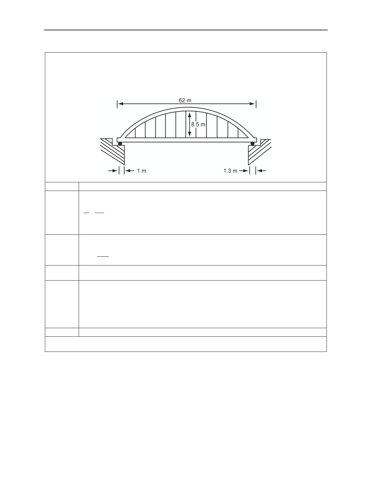
Problem. Using the top-attack bridge calculation, determine the attack method for demolishing a simply
supported, bowstring bridge with the following measurements.
a. Length (L): 62 meters
b. Height (H): 8.5 meters
c. Average length of bearing supports (LS): 1.15 meters
Step 1
Refer to Appendix H. Table H-2, page H-2, lists the top-attack method for this bridge.
Determine the height-to-length ratio (H/L).
H
8.5
Step 2
=0.137
L
= 62
Since 0.137 is not found on the table, round UP to 0.14.
Determine the required-gap ratio (LS/L).
Step 3
L
1.15
S
=
=0.0185
L
62
Find the corresponding LS/L value (Table H-2). Since 0.0185 is not found on the table, round UP
Step 4
to 0.020.
a. Intersect the LS/L and H/L values on the table to get the value of LC/L.
LC/L = 0.082
Step 5
b. Multiply the LC/L value by the length to get LC.
LC = 0.082 x 62 = 5.08 meters
Step 6
Determine where place the charges by dividing LC in half (5.08 ÷ 2 = 2.54 meters).
Solution. The proposed cut must be 2.54 meters from either side of the midspan. Mark the bridge in this
location. This location is the centerline for the proposed cut.
Figure F-14. Top-Attack Bridge Calculation
F-12
FM 3-34.214
11 July 2007
Example Calculations
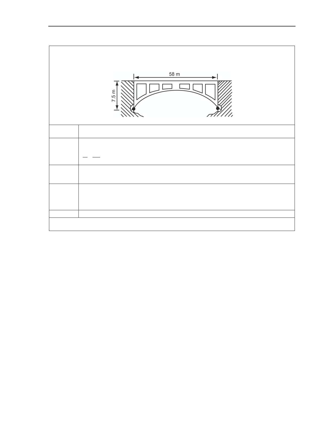
Problem. Using the arch-bridge attack calculation, determine the attack method for a continuous, concrete-
arch bridge with open spandrels and pinned footings, having the following measurements:
a. Length (L): 58 meters
b. Rise (H): 7.5 meters
Refer to Appendix H. Table H-4, pages H-4 through H-8, lists the bridge-attack method for this
Step 1
bridge.
Determine the height-to-length ratio (H/L):
Step 2
H
7.5
=0.129
L
= 58
Find the corresponding LC/L value (Table H-3, page H-3).
Step 3
Since 0.129 is not found on the table, round UP to 0.14. The value found below 0.14 is 0.04.
Determine the required length of the cut.
Step 4
L
C
L
C =
(L)=(0.04)58
=2.32 meters
L
Step 5
Determine where to place the charges. Place the charges at the midspan.
Solution. The proposed cut must be at the midspan. Mark the bridge in this location. This location is the
centerline for the proposed cut.
Figure F-15. Arch-Bridge Attack Calculation
11 July 2007
FM 3-34.214
F-13

This page is intentionally left blank.

Appendix G
Underwater Demolitions
This appendix outlines the techniques, tactics, and procedures used by military divers
to perform harbor clearance, impalement blasting, trenching, tunneling, channel
alteration, and sandbar removal. The primary use of explosives in underwater salvage
is harbor clearance. Explosives are used to clear ship passages and for cutting
wreckage. When using demolitions with manual, underwater-cutting techniques,
explosive cutting has extensive application in
“cut-and-lift” harbor clearance
operations, and increase the use of certain
“patch-and-pump” situations when
portions of a wreck are refloated individually. Other underwater salvage operations
requiring the use of explosives include rock and coral blasting, channel or harbor
bottom altering, concrete and masonry blasting, steel breaking and cutting, ship
cutting, and removal of ship propellers. These operations may be used alone or with
harbor clearance.
HARBOR CLEARANCE
G-1. A harbor may be blocked deliberately to deny its use to an enemy or as a result of bombardment. In
one case, ships and other objects will be positioned and sunk in locations to make harbor clearance
difficult. In another case, obstruction will be haphazard. When harbors are blocked intentionally, it is
possible that explosives have been placed as hazards for harbor clearance personnel. When harbors are
obstructed as a result of bombardment, there may be explosives in sunken ships or scattered on the harbor
bottom.
DANGER
The rendering safe of underwater explosive ordnance is outside
the scope of salvage operations. Whenever the presence of
explosives is known or suspected, Navy EOD personnel should
clear the area before salvage operations begin. Failure to comply
may cause death or permanent injury.
SHIP SALVAGE
G-2. Before salvage operations begin, determine whether sunken ships are to be dispersed by explosives,
converted to mooring or docking facilities, or salvaged for reuse or scrap. The condition of a sunken ship
and the need for it may dictate that the ship be salvaged for reuse. The need for scrap steel and the
availability of outgoing supply channels may make salvage for scrap the prime consideration. On the other
hand, the immediate tactical need for the harbor may make it imperative that all sunken ships be dispersed
or flattened so the harbor will be cleared in the minimum time.
G-3. Unsalvageable vessels and other equipment can be marked and left in place, sectioned and removed,
flattened, dispersed, or settled with explosives. Whether a particular ship is dispersed completely in one
continuous operation is determined by the overall situation at the site. If a well-blocked harbor is made
usable first for shallow-draft vessels and then for deeper-draft ships, the upper portions of several obstacles
are dispersed and followed by progressive demolition of the lower portions of the same obstacles. If a
single sunken ship blocks a channel, the entire ship may be dispersed in a single operation. Depending on
the particular situation, sectioning, flattening, dispersal, and settlement methods can be used.
11 July 2007
FM 3-34.214
G-1

Appendix G
SECTIONING
G-4. Sectioning involves cutting the vessel into manageable pieces. It also involves removing the pieces to
designated locations.
FLATTENING
G-5. Flattening uses explosives to first remove the superstructure and then crushes the hull to the bottom.
The stages in which a ship is flattened will depend on the position of the ship with respect to the bottom. A
ship resting on its side presents a different problem from one that is sitting upright on the bottom. In most
cases, the masts and rigging are removed first, then the superstructure is removed or dispersed, and finally
the hull itself is flattened. In all hull-flattening operations, charges are placed to take advantage of the
weight of and existing stresses in structural members. The greater the stress on the member, the less
explosive needed to cut or break it.
DISPERSAL
G-6. The time limitation in the emergency clearing of a harbor or channel usually does not permit the
salvage of a sunken ship, either by raising or by cutting it up for scrap. When time is essential, dispersal of
the sunken ship by demolition is the most effective way of clearing the harbor or channel. The hull is
dispersed by placing heavy demolition charges inside each end of the hull and one heavy charge in the
center. Detonation of the charges is simultaneous. Usually the heavy planking or frames take most of the
ribs and frames with it, forcing the hull outward by the explosion. Ribs or frames left standing must be cut
individually.
SETTLEMENT
G-7. Explosives can be used to prevent the ship from settling on the bottom. Explosives can also be used
to make the ship settle farther on the bottom.
Prevention. When a ship is to be salvaged, the bottom can be compacted beneath it to prevent
further settling. This is done by driving detonating powder points into the bottom around the
hull. For this purpose, the powder points should be loaded with an explosive with a low rate of
detonation, such as ammonium nitrate. Charges must be light enough so the hull of the ship is
not damaged.
Future settlement. When a ship resting on a sandy or muddy bottom is to be dispersed or
flattened, it should be settled as deeply as possible. Settle it by blowing holes in the hull along
the bottom to reduce the bearing surface. This allows the bottom material to ooze into the hull.
Added settling will result from increasing the weight of the ship by filling the voids with sand,
mud, or gravel through an airlift.
Note. Removing large sections of steel may require a surface crane or winch from the supported
unit.
IMPALEMENT BLASTING
G-8. Using explosives to remove an impaling point is a slow process. Extra caution should be used when
blasting rock or coral that is in contact with the hull of a watercraft. This will avoid driving the rock further
into the hull or inflicting shock wave damage on the ship. The only procedure feasible under such
circumstances is to begin with very small charges per shot. After each blast, the results are checked and
either the charge size is increased or the step is repeated by using the same size charge. Efforts to speed the
process are likely to cause additional damage. Engineer divers are trained to use special procedures and
techniques and are equipped to perform impalement-blasting operations.
G-2
FM 3-34.214
11 July 2007
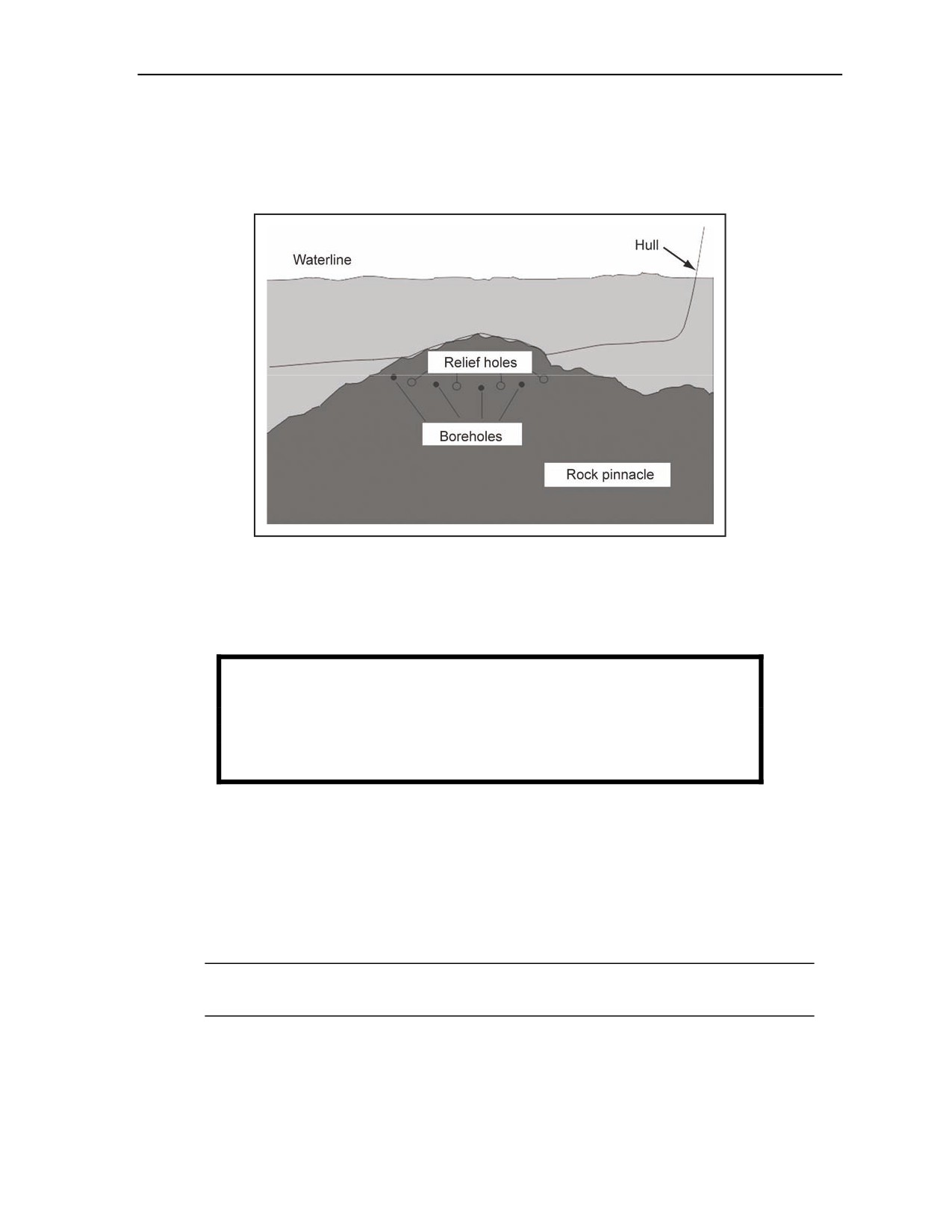
Underwater Demolitions
IMPALEMENT BLASTING OUTSIDE THE HULL
G-9. A hydraulic sinker drill is used to drill a pattern of small boreholes along the planned cut line,
leaving some holes uncharged. Relief holes will vent explosive pressure and increase the shattering effect
by decreasing the lateral burden about the charge (Figure G-1).
Figure G-1. Impalement Blasting Outside the Hull
G-10. A large internal patch of concrete is poured, if available, into a form inside the hull around the point
of impalement. This establishes a medium that transmits the explosive shock wave from the water through
the hull plate. Because the shock is absorbed and not reflected, larger charges per blast are possible without
causing damage.
WARNING
As always, even when concrete is being used, treat initial shots
as tests rather than one-shot solutions. Failure to comply could
result in immediate personal injury or damage to equipment.
G-11. Small charges (about 1/8 to 1/4 pound of explosives) are used initially. To avoid creating a large
shock wave, small charges are used in a delay sequence. This process is continued until the impaling point
is removed.
IMPALEMENT BLASTING WITHIN THE HULL
G-12. The pinnacle is attacked from within the ship when external access to the impaling point is dangerous
or impossible (Figure G-2, page G-4) The pinnacle is attacked by—
Cementing the rock to the hull so that it plugs the hole (Figure G-3, page G-4).
Note. The ship can then be freed by shattering small portions of the impaling point and breaking
the rock free, about 2 feet outside the hull, with each round of explosives.
Using a hydraulic sinker drill to drill a pattern of small boreholes along the planned cut line,
leaving some of the holes uncharged.
11 July 2007
FM 3-34.214
G-3
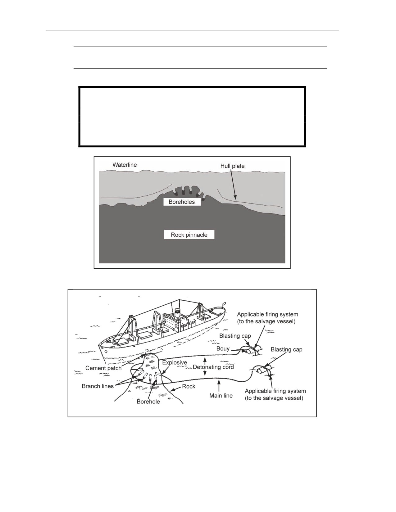
Appendix G
Note. Relief holes will vent explosive pressure and increase the shattering effect by decreasing
the lateral burden about the charge.
Repeating the procedure until the obstacle is removed.
WARNING
Open doors and cargo hatches to prevent an internal
overpressurization of the hull. A flood control plan is required.
Failure to comply could result in immediate personal injury or
damage to equipment.
Figure G-2. Impalement Blasting Within the Hull
Figure G-3. Freeing a Ship From a Rock Pinnacle
G-4
FM 3-34.214
11 July 2007
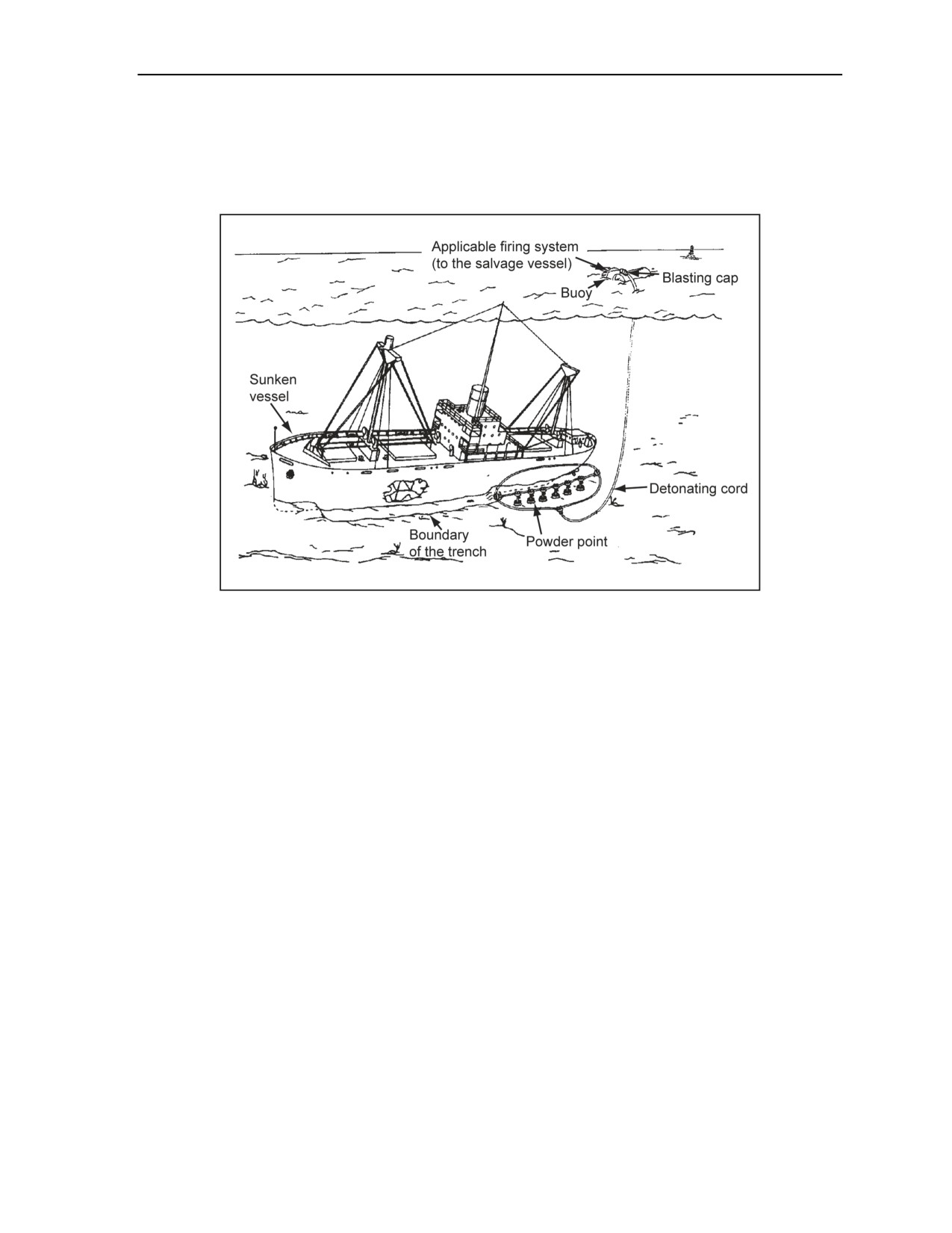
Underwater Demolitions
TRENCHING AND TUNNELING
G-13. Trenching and tunneling in a hard rock bottom requires the use of explosives. Such operations,
adjacent to a ship that is to be salvaged, must be done with charges light enough so that the ship itself will
not be damaged. After blasting in rock, an airlift may be needed to remove material (Figure G-4).
Figure G-4. Trenching and Tunneling With Explosives Alongside a Ship
POWDER POINTS
G-14. Powder points are constructed by driving or jetting pipes into the bottom of a harbor or channel and
then placing charges of composition C4 in the pipes. Charges are made above-water, then the diver places
them into the pipes. To construct powder points, use the following procedures:
Above-water.
Prepare the plastic explosive charges.
Tie a double overhand knot in detonating cord of sufficient length to lower the charge to the
bottom of the pipe.
Underwater.
Place the powder point perpendicular to the material to be moved.
Drive the powder point to a depth equal to that of the desired grade line, plus the distance
between the points.
Mold the knotted detonating cord into the top half of the prepared, plastic-explosive charge,
and place the charge into each pipe. Ensure that alternate points contain different charges so
that the detonation effects will not cancel each other.
Join individual charges together by a branchline, and connect them to the ring main. Attach
the ring main to the surface initiating system by using a double main line of detonating
cord.
BOREHOLES
G-15. When powder points cannot be used, place charges in boreholes spaced and staggered the same way
as powder points. Boreholes for powder charges are constructed by digging or by using a hydraulic sinker
drill. When a sinker drill is unavailable or time is limited, use small-shaped charges to blast small-diameter
holes into the rock or hard bottom. Boreholes are enlarged by using additional explosives.
11 July 2007
FM 3-34.214
G-5
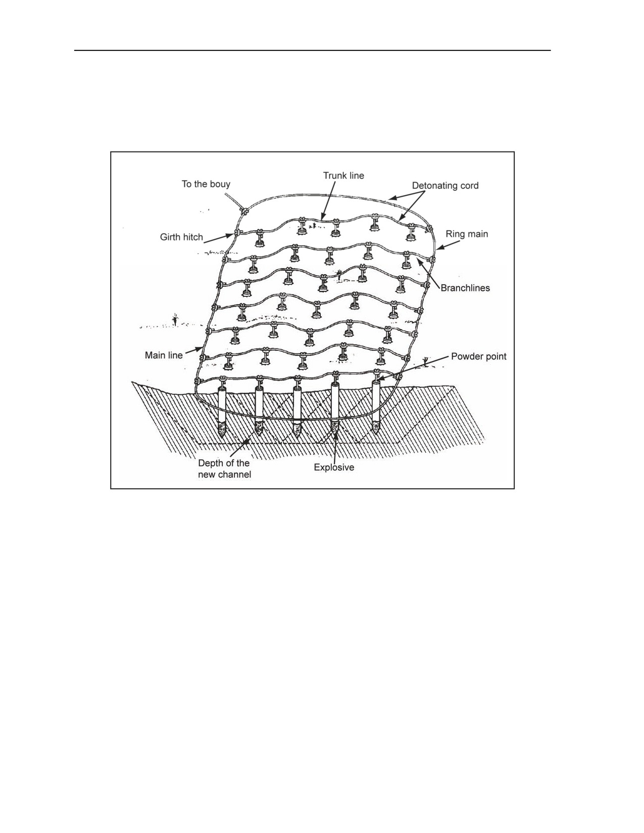
Appendix G
CHANNEL ALTERATION
G-16. Channel alteration is an expanded trenching operation. The convenience of straight channels and
free, open anchorages for ship handling must be sacrificed to speed and the most expedient means of
making the harbor usable. Where a deep channel is necessary, a large amount of blasted bottom material
must be removed with the aid of dredging equipment for ultimate disposal (Figure G-5).
Figure G-5. Channel Alteration
POWDER POINTS
G-17. For constructing powder points, refer to paragraph G-14. The procedure described here is used as the
last procedure for completing underwater procedures (use this procedure for channel alteration only).
G-18. Widen or straighten a channel by placing a light charge along the bottom of the existing channel to
be detonated at the same time as the charges in the side being blasted. This prevents the material blasted
from the side from settling in the existing channel.
BOREHOLES
G-19. Where powder points cannot be used, place charges in boreholes that are spaced and staggered the
same way as powder points. The boreholes for powder charges are constructed by digging or by using a
hydraulic sinker drill. When a sinker drill is unavailable or time is limited, use small-shaped charges to
blast small-diameter holes into the rock or hard bottom. Boreholes are enlarged by using more explosives.
G-6
FM 3-34.214
11 July 2007
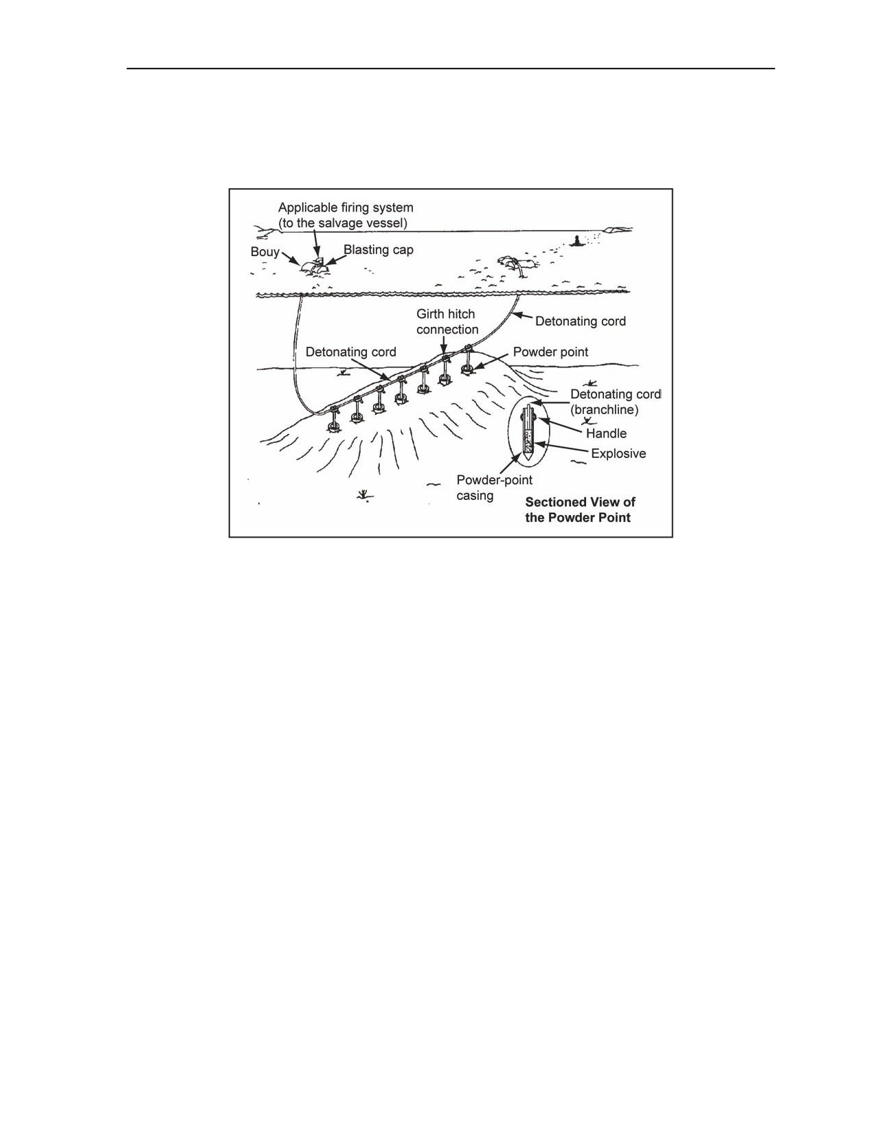
Underwater Demolitions
SANDBAR REMOVAL
G-20. When sandbars cover a large area or the depth of the cut makes the use of a water jet to scour away
sand impractical, use demolitions powder points (Figure G-6). Refer to the previous paragraphs for the use
of powder points to trench, tunnel, and alter.
Figure G-6. Sandbar Removal
DOUBLE-WATERPROOF FIRING ASSEMBLY
G-21. The double-waterproof firing assembly (DWFA) is used in water as an inexpensive and time-saving
method of ensuring positive detonation of the main charge that has a detonating cord as the priming agent.
The DWFA can be constructed from floatable materials other than wood, such as bubble wrap cushioning
material or a steel drum (Figure G-7, page G-8).
11 July 2007
FM 3-34.214
G-7
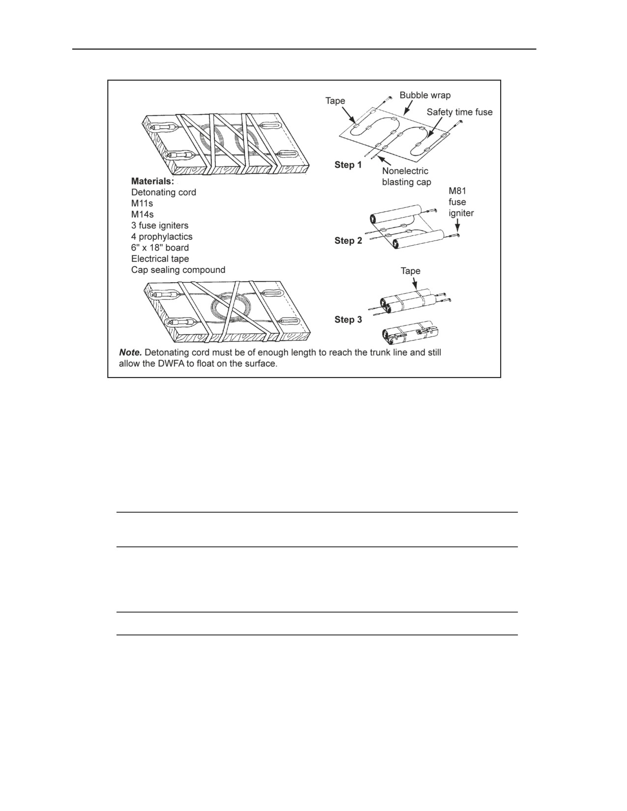
Appendix G
Figure G-7. DWFA Board
DOUBLE-WATERPROOF FIRING ASSEMBLY BOARD OR BUBBLE WRAP PREFIRING
PROCEDURES
G-22. When performing prefiring procedures using DWFA board or bubble wrap, the following
precautions should be used:
Observe standard explosive and nonelectric firing-safety precautions.
Ensure that the DWFA remains on the surface of the water with the fuse igniter end securely
taped to board or bubble wrap.
Note. This prevents the rapid burning of the time fuse due to water pressure, which could cause
premature detonation.
Attach the DWFA to the support line or the strain relief buoy, then attach the detonating cord to
the blasting caps.
Untape the coils of the time fuse, and place them face down into the water to prevent them from
burning through.
Note. This could result in premature detonation.
Use multiple DWFAs on larger targets if necessary.
DETONATING CORD PREPARATION
G-23. The paragraphs below describe how to prepare detonating cord. Discussed is how to prepare a
support- or strain-relief line, an anchor, a detonating cord (doubling), and a marker buoy.
G-8
FM 3-34.214
11 July 2007
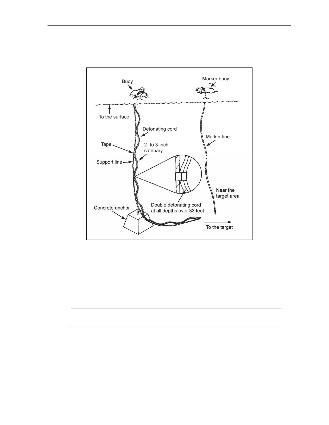
Underwater Demolitions
SUPPORT- OR STRAIN-RELIEF LINE
G-24. The support- or strain-relief line is a strength member used to reinforce the firing train. It is attached
to the DWFA and runs down to either the target or an anchor on the bottom (Figure G-8).
Figure G-8. Typical Detonating Cord Preparation
G-25. To reduce the possibility of breaking the firing train due to tension on the detonating cord, a support-
or strain-relief line is connected to the detonating cord. The detonating cord is attached to the support or
strain-relief line with plastic tie straps (zip ties). The tie straps are attached about every 3 feet with a 2- to
3-inch catenary (slack) between connecting points. One of the following should be used to attach the
detonating cord to the trunk line:
Gregory knot.
Girth hitch with an extra turn connection.
Detonating cord connector with a right-angle connection.
Note. Several unconventional knots can be used, such as the Gregory knot and right-angle knot
connection, to attach the detonating cord to the trunk line.
ANCHOR
G-26. The support or strain-relief line is attached with detonating cord to the target or to an anchor as close
to the main charge as possible. This will avoid cap-and-charge separation due to wave action, current, and
so forth.
11 July 2007
FM 3-34.214
G-9

Appendix G
DETONATING CORD (DOUBLING)
G-27. Detonating cord leads should be doubled at all depths over 33 feet. The double-strand detonating
cord will be tie-strapped together to the support- or strain-relief line about every 3 feet.
MARKER BUOY
G-28. An additional marker buoy is attached to the target areas. This bouy is used for relocation when
returning for shot investigation.
G-10
FM 3-34.214
11 July 2007

Appendix H
Attacking Bridges With Demolitions
The attack methods in this appendix are for the most common bridge types; however,
they are not all inclusive. When faced with unusual construction methods or materials
(for example, hayricks that are linear shaped charges used by host NATO countries),
the responsible engineer should adapt one of the recommended methods or
recategorize the bridge as a miscellaneous bridge and design the demolition using the
principles discussed in Chapter 4. Use Tables H-1 through H-3, pages H-1 through
H-3, to determine the required clearance to prevent jamming. Use Table H-4, pages
H-4 through H-8, and Table H-5, pages H-9 through H-15, for the attack methods.
Table H-1. Minimum ER Values For Bottom Attack (Percent)
H/L
0.01
0.02
0.03
0.04
0.05
0.06
0.07
0.08
0.09
0.10
ER/L
0.0002
0.0008
0.0020
0.0030
0.0050
0.0070
0.0100
0.0130
0.0160
0.0200
H/L
0.11
0.12
0.13
0.14
0.15
0.16
0.17
0.18
0.19
0.20
ER/L
0.0240
0.0290
0.0340
0.0390
0.0440
0.0500
0.0570
0.0630
0.0700
0.0770
where—
H = beam, truss, and bow depth in meters (includes the deck)
L = length of span for attack measured from end to end of the longitudinal members which support the deck
in meters
ER = required end clearance in meters
Notes.
1. Go UP to the next higher value if the result of H/L is not on the chart exactly as calculated. For example, H/L = 0.076,
use the column headed 0.08. Read down that column to determine ER/L. In this case, ER/L = 0.0130.
2. Multiply the ER/L value determined from the chart by L to get ER.
11 July 2007
FM 3-34.214
H-1

Appendix H
Table H-2. Minimum LC Values For Top Attack (Midspan)
Ls
----
L
L
( C
)
Ratio of Section Removed to Span Length
L
-
--
0.004
0.006
0.008
0.010
0.012
0.014
0.016
0.018
0.020
0.030
0.040
0.050
0.060
0.080
0.100
L
0.01
0.003
0.003
0.004
0.004
0.005
0.005
0.005
0.006
0.006
0.007
0.009
0.010
0.011
0.013
0.015
0.02
0.005
0.006
0.007
0.008
0.009
0.010
0.011
0.011
0.012
0.015
0.017
0.019
0.022
0.026
0.030
0.03
0.008
0.009
0.011
0.012
0.014
0.015
0.016
0.017
0.018
0.022
0.026
0.029
0.033
0.039
0.045
0.04
0.011
0.013
0.015
0.016
0.018
0.019
0.021
0.022
0.023
0.029
0.034
0.039
0.043
0.052
0.060
0.05
0.013
0.016
0.018
0.020
0.022
0.024
0.026
0.028
0.029
0.036
0.043
0.049
0.054
0.065
0.075
0.06
0.015
0.019
0.022
0.025
0.027
0.029
0.031
0.033
0.035
0.044
0.051
0.058
0.065
0.078
0.090
0.07
0.018
0.022
0.026
0.029
0.031
0.034
0.036
0.039
0.041
0.051
0.060
0.068
0.076
0.091
0.105
0.08
0.021
0.025
0.029
0.033
0.036
0.039
0.042
0.044
0.047
0.058
0.068
0.078
0.087
0.104
0.120
0.09
0.023
0.028
0.033
0.037
0.040
0.044
0.047
0.050
0.053
0.065
0.077
0.087
0.097
0.116
0.135
0.10
0.026
0.032
0.036
0.041
0.045
0.049
0.052
0.055
0.058
0.073
0.085
0.097
0.108
0.129
0.150
0.11
0.028
0.035
0.040
0.045
0.049
0.053
0.057
0.061
0.064
0.080
0.094
0.107
0.119
0.142
0.165
0.12
0.031
0.038
0.044
0.049
0.054
0.058
0.062
0.066
0.070
0.087
0.102
0.116
0.130
0.155
0.180
0.13
0.033
0.041
0.047
0.053
0.058
0.063
0.067
0.072
0.076
0.095
0.111
0.126
0.140
0.168
0.195
0.14
0.036
0.044
0.051
0.057
0.063
0.068
0.073
0.077
0.082
0.102
0.119
0.136
0.151
0.181
0.210
0.15
0.038
0.047
0.054
0.061
0.067
0.073
0.078
0.083
0.088
0.109
0.128
0.145
0.162
0.194
0.225
0.16
0.041
0.050
0.058
0.065
0.072
0.078
0.083
0.088
0.093
0.116
0.136
0.155
0.173
0.207
0.240
0.17
0.043
0.053
0.062
0.069
0.076
0.082
0.088
0.094
0.099
0.124
0.145
0.165
0.184
0.220
0.255
0.18
0.046
0.056
0.065
0.073
0.080
0.087
0.093
0.099
0.105
0.131
0.154
0.175
0.194
0.233
0.270
0.19
0.049
0.060
0.069
0.077
0.085
0.092
0.099
0.105
0.111
0.138
0.162
0.184
0.205
0.246
0.285
0.20
0.051
0.063
0.073
0.081
0.089
0.097
0.104
0.110
0.117
0.145
0.171
0.194
0.216
0.259
0.300
Note. If the results of Ls/L or H/L are not on the chart exactly as calculated, go UP to the next higher value on the chart. For
example, if H/L = 0.021, use 0.03; if Ls/L = 0.0142, use 0.016. Intersect the Ls/L and H/L values on the chart to get the value
of LC/L. Multiply the LC/L value by L to get LC.
H-2
FM 3-34.214
11 July 2007

Attacking Bridges With Demolitions
Table H-3. Minimum LC Values For Arch and Pinned-Footing Bridge Attacks
H/L
0.040
0.060
0.080
0.100
0.120
0.140
0.160
0.180
0.200
LC/L
0.003
0.007
0.013
0.020
0.030
0.040
0.053
0.067
0.083
H/L
0.220
0.240
0.260
0.280
0.300
0.320
0.340
0.360
—
LC/L
0.100
0.130
0.150
0.170
0.200
0.230
0.270
0.300
—
where—
H = rise for arch or portal bridges (measure the rise) [in meters] from the springing or bottom of the support
leg to the deck or top of the arch, whichever is greater)
L = length of span for attack between the centerlines of the bearings (in meters)
LC = required length of the span removed (in meters)
Note. If the result of H/L is not on the chart exactly as calculated, go UP to the next higher value on the chart. For example,
if H/L = 0.089, use 0.100 to determine LC/L. In this case, LC/L = 0.02. Multiply the LC/L value by L to get LC. For example,
0.02 x L = LC.
11 July 2007
FM 3-34.214
H-3
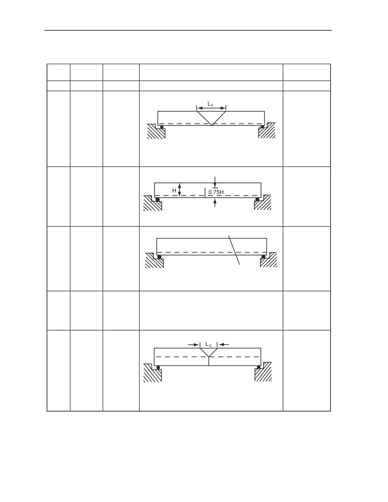
Appendix H
Table H-4. Attack Methods on Simply Supported Bridges
Sub-
Serial
Type
Attack Method
Remarks
category
a
b
c
d
e
Top attack:
Through
Steel
1
bridge,
None
beam
Method I
1. Cut at the midspan.
2. Cut the beams, including the bottom flange in a
“V.”
3. Do not consider cutting the deck.
Bottom attack: E is greater than ER
Through
Steel
2
bridge,
None
beam
Method II
1. Cut at the midspan to 0.75H, as shown.
2. Cut the deck across the full bridge width.
Angled attack:
Through
End clearance
Steel
3
bridge,
is not a
beam
Method III
consideration.
1. Cut between the 1/3 span and the midspan.
2. Cut the deck across the full bridge width.
Bottom attack: E is less than ER
Through
1. Cut at the midspan to 0.75H.
Steel
4
bridge,
2. Cut the deck across the full bridge width.
None
beam
Method IV
3. Attack one abutment or pier to create sufficient end
clearance.
Top attack:
Through
Steel
5
bridge,
None
beam
Method V
1. Cut at the midspan.
2. Cut the bridge as shown where the deck is located
well above the beam bottom.
3. Do not consider cutting the deck.
H-4
FM 3-34.214
11 July 2007
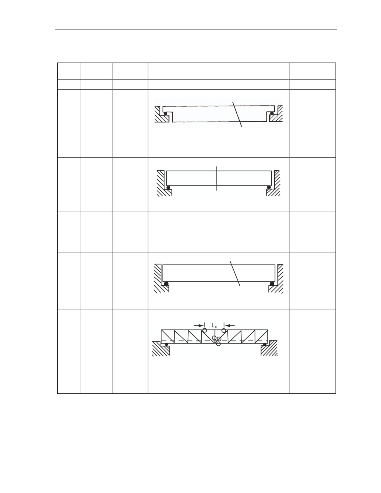
Attacking Bridges With Demolitions
Table H-4. Attack Methods on Simply Supported Bridges
Sub-
Serial
Type
Attack Method
Remarks
category
a
b
c
d
e
Angled attack:
1.
Configuration
found in
cantilever and
Deck
Steel
suspended-
6
bridge, top
beam
span bridges.
support
1. Cut between the 1/3 span and the midspan.
2. End
2. Cut the deck across the full bridge width.
clearance is
not a
consideration.
Bottom attack: E is greater than ER
Deck
bridge,
Steel
7
bottom
None
beam
support,
Method I
1. Cut at the midspan.
2. Do not consider cutting the deck.
Deck
Bottom attack: E is less than ER
bridge,
1. Cut at the midspan.
Steel
8
bottom
2. Do not consider cutting the deck.
None
beam
support,
3. Attack one abutment or pier to create sufficient end
Method II
clearance.
Angled attack:
Deck
bridge,
End clearance
Steel
9
bottom
is not a
beam
support,
consideration.
Method III
1. Cut between the 1/3 span and the midspan.
2. Cut the deck across the full bridge width.
Top attack:
Through
Steel
10
bridge,
None
truss
Method I
1. Cut at the midspan.
2. Cut the top chord twice, vertically (if necessary),
diagonals, and bottom chord.
3. Remove the wind bracing over the midspan.
4. Do not consider cutting the deck.
11 July 2007
FM 3-34.214
H-5
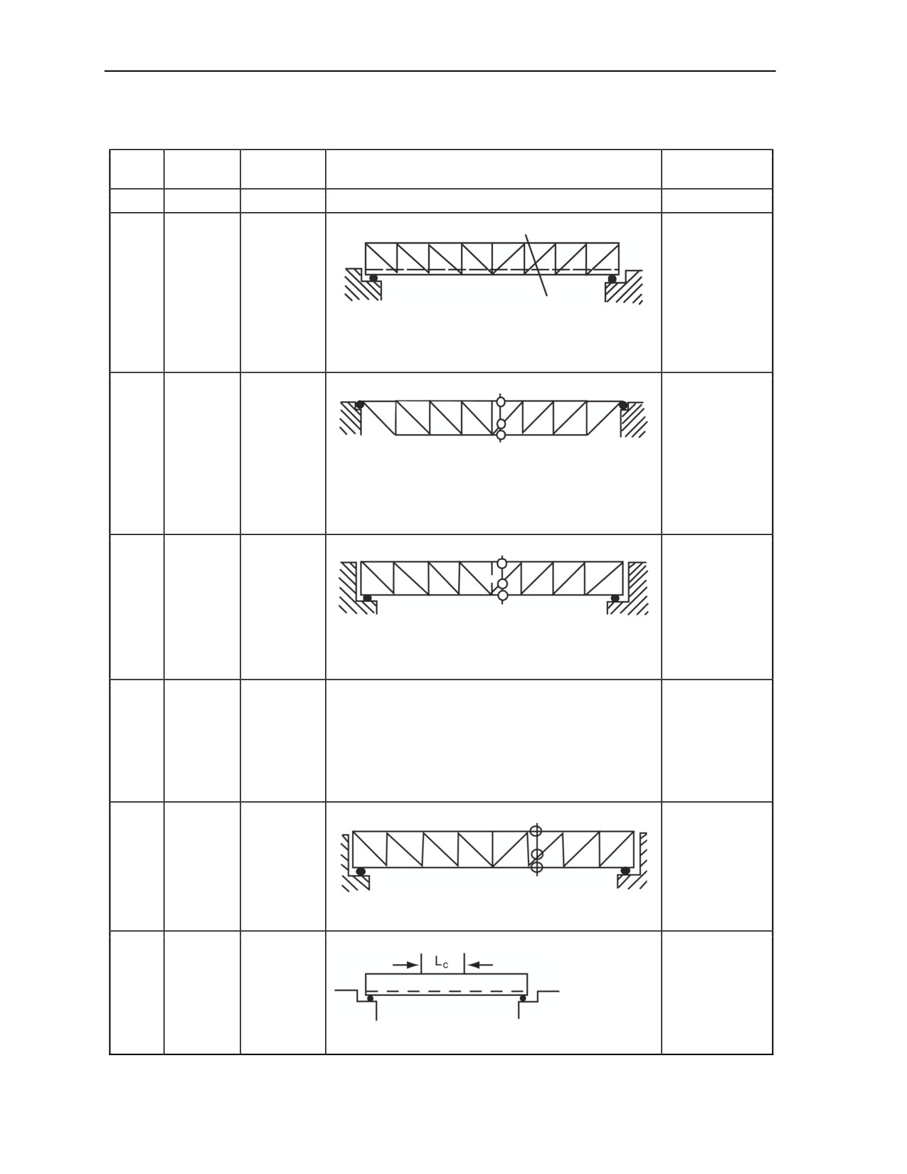
Appendix H
Table H-4. Attack Methods on Simply Supported Bridges
Sub-
Serial
Type
Attack Method
Remarks
category
a
b
c
d
e
Angled attack:
Through
Steel
11
bridge,
None
truss
Method II
1. Cut between the 1/3 span and the midspan.
2. Cut the top chord, diagonals, and bottom chord in
one bay only.
3. Cut the deck across the full bridge width.
Bottom attack:
1.
Configuration
found in
cantilever and
Deck
Steel
1. Cut between the 1/3 span and the midspan.
suspended-
12
bridge, top
truss
2. Cut the top chord, diagonals, and bottom chord in
span bridges.
support
one bay only.
2. End
3. Do not consider cutting the deck.
clearance is
not a
consideration.
Bottom attack: E is greater than ER
Deck
bridge,
Steel
13
bottom
None
truss
support,
1. Cut at the midspan.
Method I
2. Cut the top chord, diagonals, and bottom chord in
one bay only.
3. Do not consider cutting the deck.
Bottom attack: E is less than ER
Deck
1. Cut at the midspan.
bridge,
2. Cut the top chord, diagonals, and bottom chord in
Steel
14
bottom
one bay only.
None
truss
support,
3. Do not consider cutting the deck.
Method II
4. Attack one abutment or pier to create sufficient end
clearance.
Angled attack:
Deck
bridge,
End clearance
Steel
15
bottom
is not a
truss
support,
consideration.
Method III
1. Cut between the 1/3 span and midspan.
2. Cut the deck across the full bridge width.
Bottom attack:
This method
Through
16
Concrete
applies to slab
bridge
bridges only.
1. Cut at the midspan.
2. Cut the deck across the full bridge width.
H-6
FM 3-34.214
11 July 2007
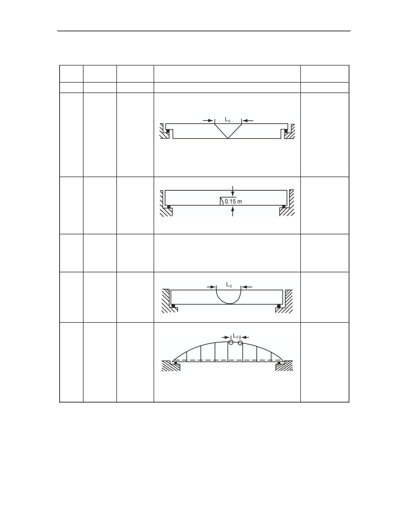
Attacking Bridges With Demolitions
Table H-4. Attack Methods on Simply Supported Bridges
Sub-
Serial
Type
Attack Method
Remarks
category
a
b
c
d
e
1.
Configuration
Top attack:
found in
cantilever and
suspended-
Deck
span bridges.
17
Concrete
bridge, top
2. Remove
support
Cut at the midspan with a concrete-stripping charge.
concrete for LC
distance to the
full width and
depth of
beams.
Bottom attack: E is greater than ER
1. This method
applies to slab
Deck
bridges only.
bridge,
2. Sufficient
18
Concrete
bottom
reinforcing bars
support,
are cut to
Method I
Cut at the midspan with hayricks.*
cause bridge
collapse.
Deck
Bottom attack: E is less than ER
bridge,
This method
1. Cut at the midspan with hayricks.*
19
Concrete
bottom
applies to slab
2. Attack one abutment or pier to create a sufficient
support,
bridges only.
end clearance.
Method II
Top attack: E is less than ER
Remove
Deck
concrete for LC
bridge,
distance to full
20
Concrete
bottom
width and
support,
depth of
Method III
beams.
Cut at the midspan with a concrete-stripping charge.
Top attack:
21
Bowstring
Normal
None
1. Cut at the midspan.
2. Cut the bow in two places.
3. Cut all hangers between the bow cuts.
4. Do not consider cutting the deck.
11 July 2007
FM 3-34.214
H-7

Appendix H
Table H-4. Attack Methods on Simply Supported Bridges
Sub-
Serial
Type
Attack Method
Remarks
category
a
b
c
d
e
Top attack, plus girders:
Reinforced
22
Bowstring
beam or
None
truss
1. Cut the truss or beam with the appropriate method
(Serials 1 through 15).
2. Cut the bow in two places, including the hangers.
*Hayricks are not in the U.S. Army supply system.
H-8
FM 3-34.214
11 July 2007
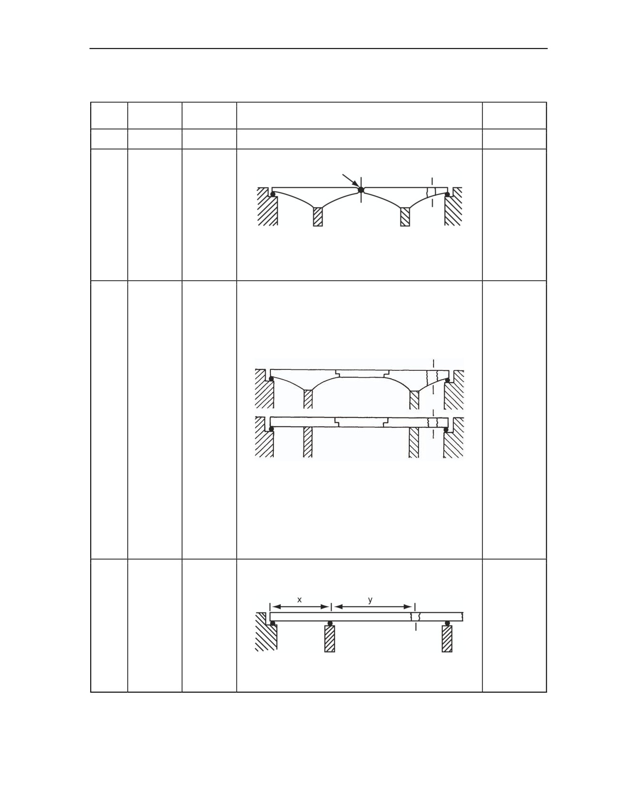
Attacking Bridges With Demolitions
Table H-5. Attack Methods on Continuous Bridges
Sub-
Serial
Type
Attack Method
Remarks
category
a
b
c
d
e
1. Cutting
Two cuts:
the anchor
span may
require a
two-stage
attack.
1
Concrete
Cantilever
2. Use a
1. Cut the anchor span as closely to the pier as practical.
concrete-
2. Cut the midspan shear joint.
stripping
charge for
the first
stage.
1. Cutting
the anchor
span may
require a
two-stage
attack.
One cut:
2. Use a
concrete-
stripping
charge for
the first
Cantilever
stage.
and
3. If
2
Concrete
suspended
demolition of
span
the
suspended
span will
create the
Cut the anchor as closely to the pier as practical.
desired
obstacle,
regard the
span as
simply
supported
and attack
accordingly.
1. Cutting
longer
One cut:
spans may
require a
Beam or
two-stage
truss with
attack.
3
Concrete
short side
2. Use a
span
concrete-
stripping
1. Cut interior span so y is greater than 1.25x.
charge for
2. If necessary, cut other interior spans as in Serial 4.
the first
stage.
11 July 2007
FM 3-34.214
H-9
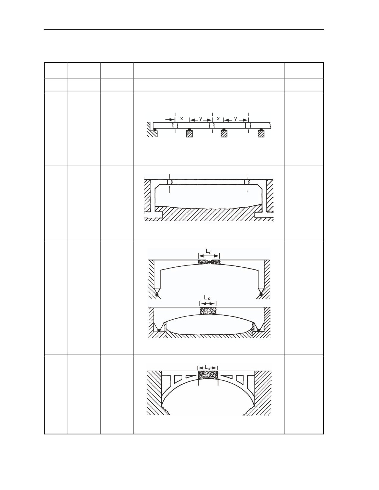
Appendix H
Table H-5. Attack Methods on Continuous Bridges
Sub-
Serial
Type
Attack Method
Remarks
category
a
b
c
d
e
1. Cutting
Two or more cuts:
these spans
may require
a two-stage
Beam or
attack.
truss without
4
Concrete
2. Use a
short side
concrete-
span
stripping
Cut the interior span so y is greater than 1.25x.
charge for
the first
stage.
Two cuts:
1. Cutting
these spans
may require
a two-stage
attack.
Portal, fixed
5
Concrete
2. Use a
footing
concrete-
stripping
charge for
Cut the span twice, close to the pier.
the first
stage.
Strip concrete:
1. Remove
all concrete
for Lc.
2. A one-
stage attack
should be
adequate.
Portal,
3. When
6
Concrete
pinned
footing
footing
conditions
are
unknown,
use Serial 5.
4. For Lc use
Table H-3,
Remove concrete from the midspan over length LC with a
page H-3.
concrete-stripping charge.
Strip concrete:
1. Applies to
arches
greater than
35 meters.
Arch, open
2. A one-
spandrel,
7
Concrete
stage attack
fixed footing,
should be
Method I
adequate.
3. For LC
Remove the concrete from the midspan over the length
use
of Lc with a concrete-stripping charge.
Table H-3.
H-10
FM 3-34.214
11 July 2007
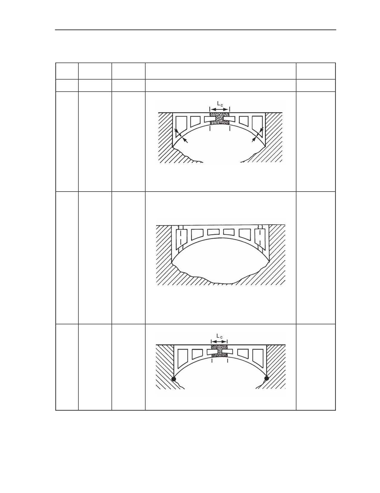
Attacking Bridges With Demolitions
Table H-5. Attack Methods on Continuous Bridges
Sub-
Serial
Type
Attack Method
Remarks
category
a
b
c
d
e
Strip concrete:
1. Applies to
arches less
than
35 meters.
Arch, open
2. A one-
spandrel,
stage attack
8
Concrete
fixed footing,
should be
Method II
adequate.
3. For LC
use
1. Remove the concrete from the midspan over the length
Table H-3,
of LC with a concrete-stripping charge.
page H-3.
2. Attack springing with hayricks* at the top face of the
arch ring.
1. This is an
alternative
to Method II,
Four cuts:
applies to
arches less
than
35 meters.
2. Two-
Arch, open
stage attack
spandrel,
will probably
9
Concrete
fixed footing,
be required.
Method III
3. Use a
concrete-
stripping
charge for
the first
stage.
4. For LC
use
Table H-3.
Strip concrete:
1. A one-
stage attack
Arch, open
should be
spandrel,
10
Concrete
adequate.
pinned
2. For LC
footing
use
Table H-3.
Remove concrete from the midspan over the length of
LC with a concrete-stripping charge.
11 July 2007
FM 3-34.214
H-11
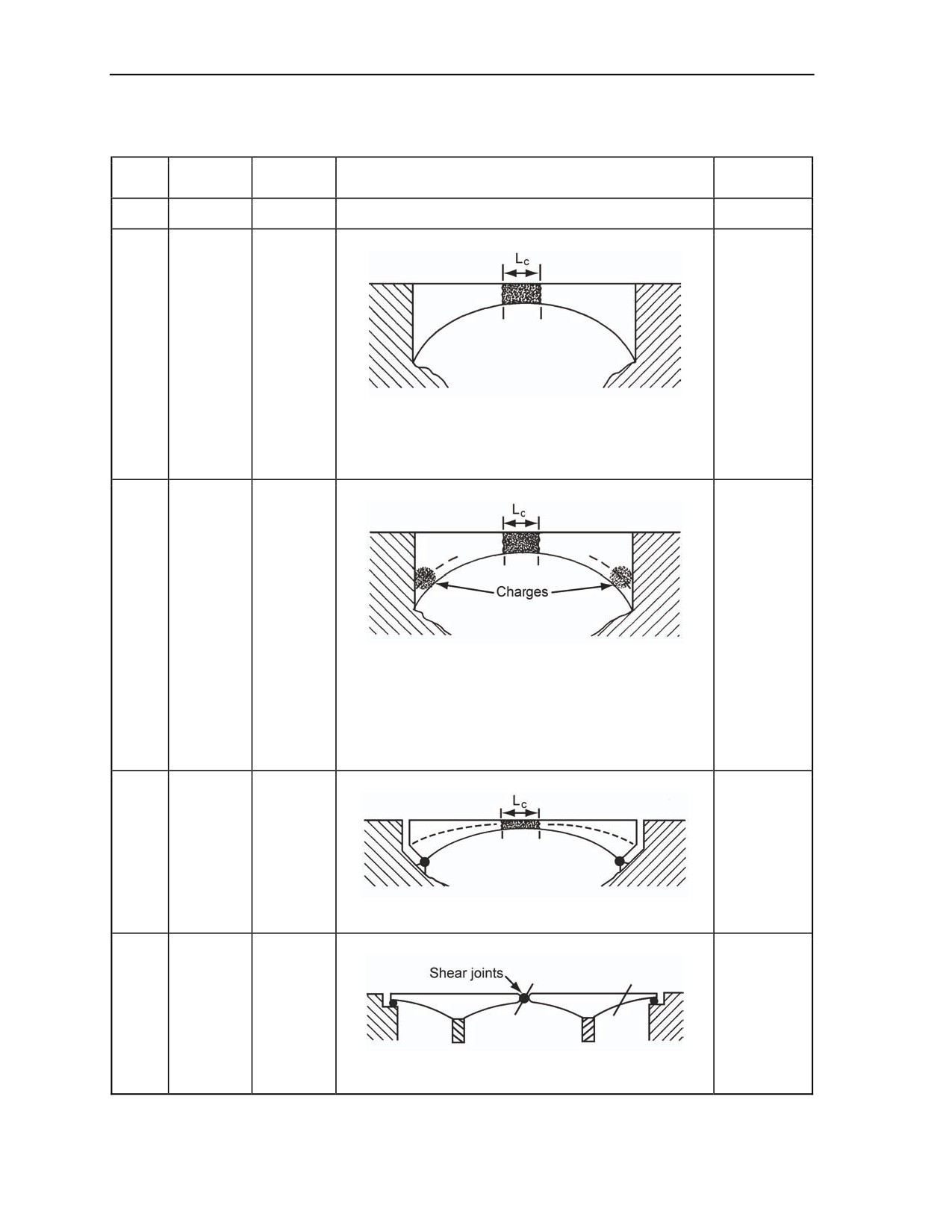
Appendix H
Table H-5. Attack Methods on Continuous Bridges
Sub-
Serial
Type
Attack Method
Remarks
category
a
b
c
d
e
Strip concrete:
1. This
applies to
arches of
span greater
than
35 meters
Arch, solid
only.
spandrel,
11
Concrete
2. A one-
fixed footing,
stage attack
Method I
should be
Remove the concrete from the midspan over the length
adequate.
of LC with a concrete-stripping charge.
3. For LC
use
Table H-3,
page H-3.
Strip concrete:
1. Applies to
arches less
than
35 meters.
Arch, solid
2. A one-
spandrel,
12
Concrete
stage attack
fixed footing,
should be
Method II
1. Remove concrete from the midspan over the length
adequate.
of LC with a concrete-stripping charge.
3. For LC
2. Attack both springing points with concrete-stripping
use
charges.
Table H-3.
Against the bottom face of the arch ring.
Against the top face (must remove the fill beneath
the roadway to access the arch ring).
Strip concrete:
1. A one-
stage attack
Arch, solid
should be
spandrel,
13
Concrete
adequate.
pinned
2. For LC
footing
use
Table H-3.
Remove concrete from the midspan over the length of
LC with a concrete-stripping charge.
Two cuts:
14
Steel
Cantilever
None
1. Cut the anchor span as closely to the pier as practical.
2. Cut the midspan shear joints.
H-12
FM 3-34.214
11 July 2007
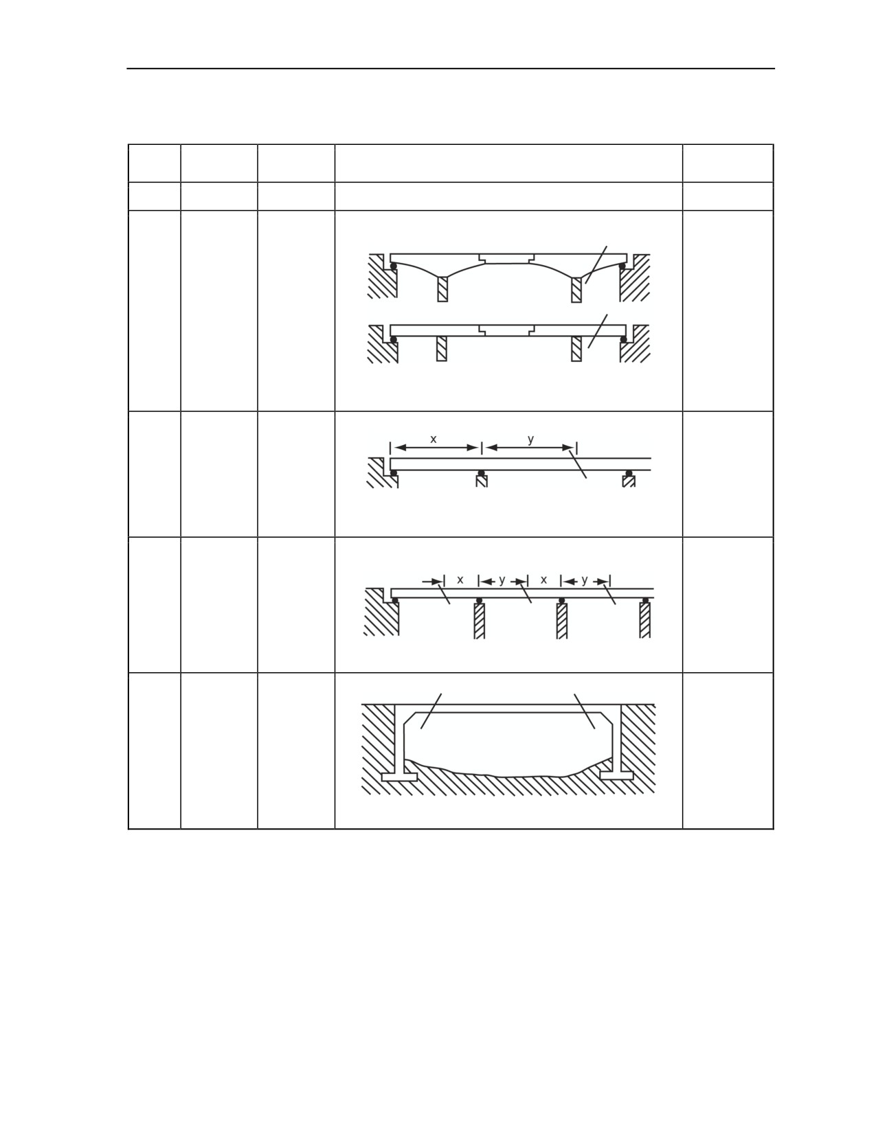
Attacking Bridges With Demolitions
Table H-5. Attack Methods on Continuous Bridges
Sub-
Serial
Type
Attack Method
Remarks
category
a
b
c
d
e
If demolition
One cut:
of the
suspended
span will
create the
Cantilever
desired
and
15
Steel
obstacle,
suspended
regard the
span
span as
simply
Cut anchor span as closely to the pier as practical.
supported,
and attack
accordingly.
One cut:
Beam or
truss with
16
Steel
None
short side
span
1. Cut the interior span so y is greater than 1.25x.
2. If necessary, cut other interior spans as in Serial 17.
Two or more cuts:
Beam or
truss without
17
Steel
None
short side
span
Cut spans so y is greater than 1.25x.
Two cuts:
Portal, fixed
18
Steel
None
footing
Cut the span twice and close to the piers.
11 July 2007
FM 3-34.214
H-13
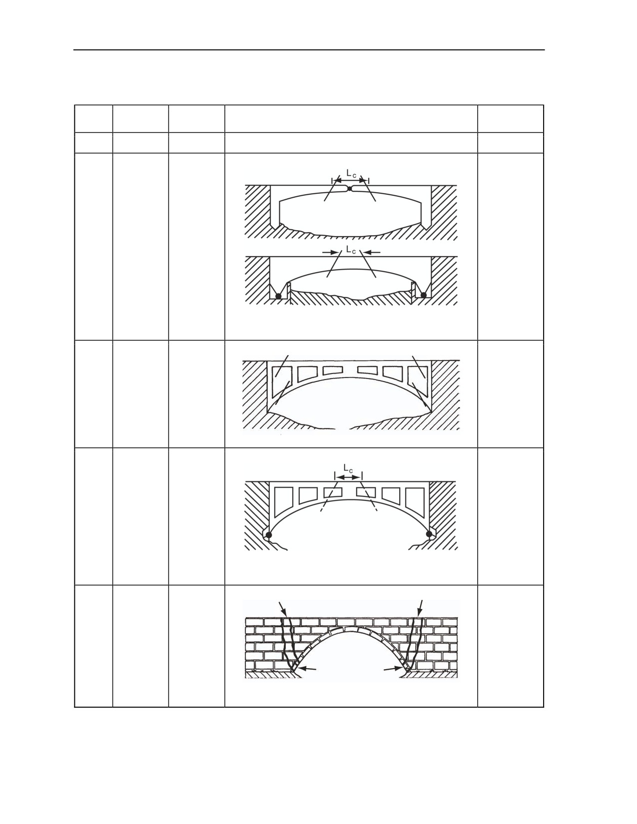
Appendix H
Table H-5. Attack Methods on Continuous Bridges
Sub-
Serial
Type
Attack Method
Remarks
category
a
b
c
d
e
Two cuts:
Portal,
Use Table
19
Steel
pinned
H-3, page
footing
H-3, for LC.
Remove the section from the midspan over the length
of LC.
Four cuts:
1. Angle
cuts about
Arch, open
70°.
20
Steel
spandrel,
2. For LC,
fixed footing
use
Table H-3.
Two cuts:
Arch, open
spandrel,
For LC, use
21
Steel
pinned
Table H-3.
footing
Remove the section from the midspan over the length
of LC.
Two cuts:
Arch,
22
Masonry
None
Method I
1. Cut at the haunches.
2. Attack the arch ring, spandrel walls, and parapet.
H-14
FM 3-34.214
11 July 2007
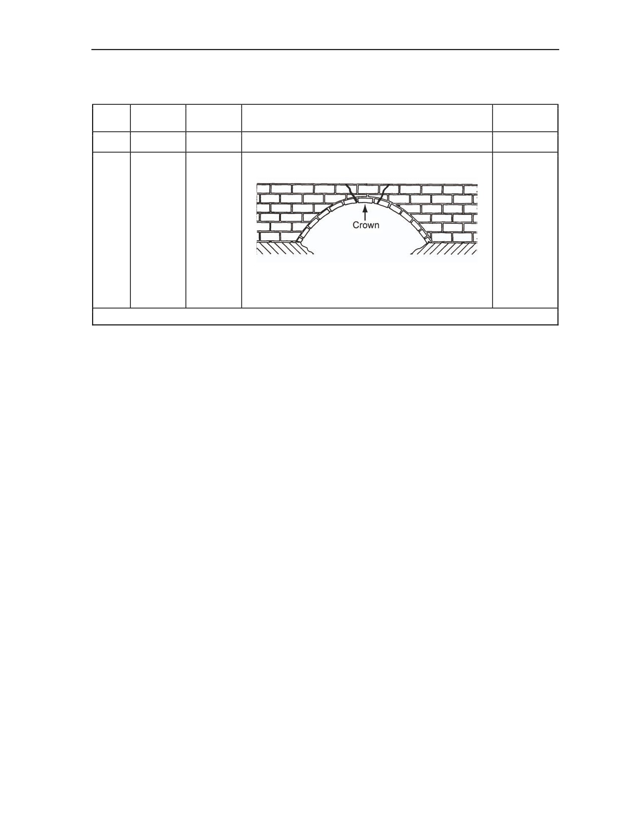
Attacking Bridges With Demolitions
Table H-5. Attack Methods on Continuous Bridges
Sub-
Serial
Type
Attack Method
Remarks
category
a
b
c
d
e
1. Use this
One cut:
method as
an alternate
to Method I
only when
time is
Arch,
insufficient
23
Masonry
Method II
to allow
attack at the
haunches.
Breach the arch ring at the crown.
2. For LC,
use
Table H-3,
page H-3.
*Hayricks are not in the U.S. Army supply system.
11 July 2007
FM 3-34.214
H-15

This page is intentionally left blank.

Appendix I
Instructions For Completing Demolitions-Related Reports
A completed target folder contains demolition orders and an obstacle folder.
Chapter 5 discusses demolition orders and the obstacle folder. The sample form
shown in Figure I-1, pages I-4 through I-8, is used to complete DA Form 2203. Page
4 of DA Form 2203 provides detailed instructions on how to complete the form.
11 July 2007
FM 3-34.214
I-1

Appendix I
DA FORM 2203, MAY 2007
Figure I-1. Sample DA Form 2203
I-2
FM 3-34.214
11 July 2007

Instructions For Completing Demolitions-Related Reports
DA FORM 2203, MAY 2007
Figure I-1. Sample DA Form 2203 (Continued)
11 July 2007
FM 3-34.214
I-3
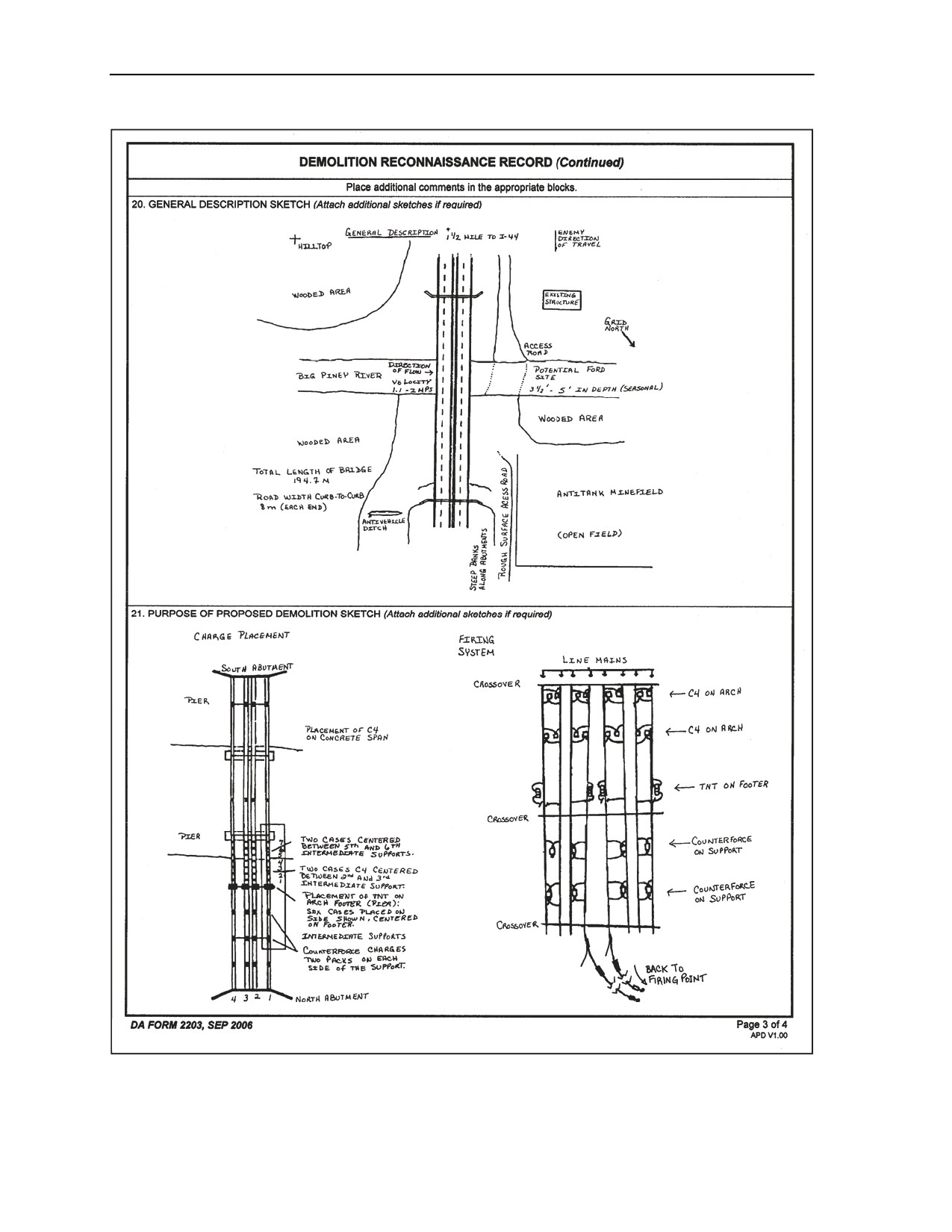
Appendix I
DA FORM 2203, MAY 2007
Figure I-1. Sample DA Form 2203 (Continued)
I-4
FM 3-34.214
11 July 2007
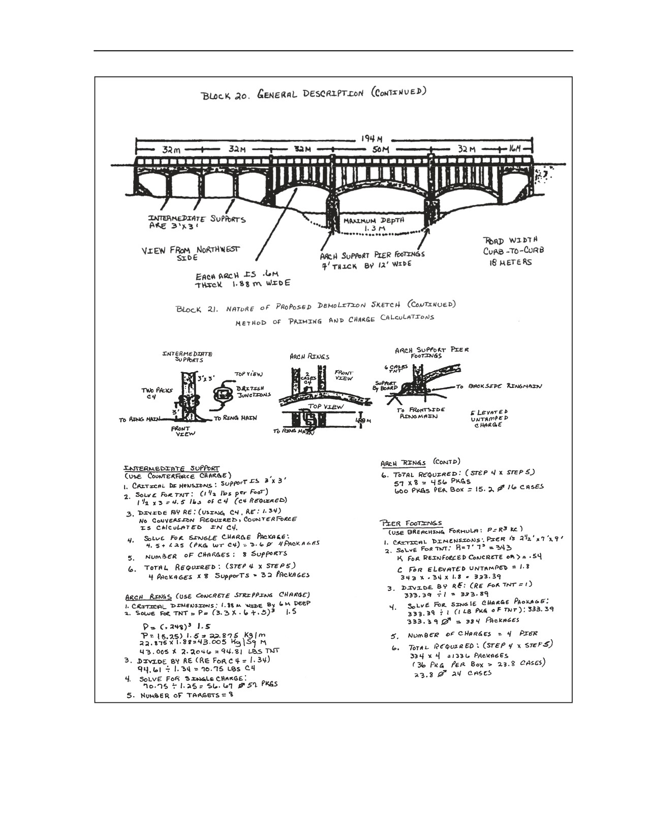
Instructions For Completing Demolitions-Related Reports
Figure I-1. Sample DA Form 2203 (Continued)
11 July 2007
FM 3-34.214
I-5

Appendix I
Figure I-1. Sample DA Form 2203 (Continued)
I-6
FM 3-34.214
11 July 2007

Appendix J
Demolition Effects Simulator Materials
This appendix contains information needed to order materials (for BOM) when
constructing DES devices. Table J-1, pages J-2 and J-3, shows the materials available
when constructing DES devices and where the materials can be obtained.
11 July 2007
FM 3-34.214
J-1

Appendix J
Table J-1. DES Materials
Materials
Sources
1
Adapter, priming
1375-00-565-4141
2
Bag, carrying M85
NSN/local purchase
3
Bag, plastic, 12 by 12 in
8105-00-837-7757
4
Box, cardboard, 7 by 1 3/4 by 1 3/4 in
Local purchase
5
Box, cardboard, 11 3/4 by 2 1/4 by 2 1/4 in
Local purchase
6
Box, wooden, bangalore torpedo
TSC/DRMO
7
Box, wooden, cratering charge
TSC/DRMO
8
Box, wooden, dynamite
TSC/DRMO
9
Box, wooden, M112
TSC/DRMO
10
Box, wooden, M118 (sheet explosive)
TSC/DRMO
11
Box, wooden, M183
TSC/DRMO
12
Box, wooden, M3
TSC/DRMO
13
Box, wooden, M2A3
TSC/DRMO
14
Box, wooden, M5A1
TSC/DRMO
15
Box, wooden, TNT
TSC/DRMO
16
Cap, blasting, electric
1375-00-756-1865
17
Cap, blasting, nonelectric
1375-00-756-1864
18
Cap, plastic end, 1 1/4 in
Local purchase
19
Cap, plastic end, 2 1/8 in
Local purchase
20
Cap, plastic end, 7 in
Local purchase
21
Chalk, field marking
Local purchase
22
Charge, shaped, metal, M2A3
Local fabrication
23
Charge, shaped, metal, M3
Local fabrication
24
Clay, pottery, moist
Local purchase
25
Cord, detonating
1375-00-965-0800
26
Coupling, plastic, 3/4 in
4730-00-472-5056
27
Coupling, plastic, 1 in
4730-00-472-5058
28
Fuse, time
1375-00-628-9033
29
Glue, super
8040-00-142-9193
30
Holder, blasting cap, M8
1375-00-926-4105
31
Label, bangalore torpedo DES, 3/8 in and 1 1/4 in
TSC
32
Label, cratering charges DES, 3/8 in and 1 1/4 in
TSC
33
Label, dynamite DES, 3/8 in and 1 1/4 in
TSC
34
Label, M112 DES, 3/8 in and 1 1/4 in
TSC
35
Label, M118 DES, 3/8 in and 1 1/4 in (sheet
TSC
explosive)
36
Label, M183 DES, 3/8 in and 1 1/4 in
TSC
J-2
FM 3-34.214
11 July 2007

Demolition Effects Simulator Materials
Table J-1. DES Materials
Materials
Sources
37
Label, M5A1 DES, 3/8 in and 1 1/4 in
TSC
38
Label, TNT DES, 3/8 in and 1 1/4 in
TSC
39
Label, shaped charge, 15 lb, DES, 3/8 in and 1 1/4 in
TSC
40
Label, shaped charge, 40 lb, DES, 3/8 in and 1 1/4 in
TSC
41
M2 crimpers
5120-00-029-0683
42
Matting, floor, 1/8 in
7220-01-025-1695
43
Oil, mineral
Local purchase
44
Sand
Local purchase
45
Sandbag
Local purchase
46
String
NSN
47
Tape, clear
7510-00-995-0455
48
Tape, duct, green
7510-00-074-5124
49
Tape, electrical, black
5970-00-419-4291
50
Tape, fabric, olive drab green
7510-00-266-5016
51
Tape, fabric, red
7510-00-074-4969
52
Tape, PSA
7510-01-057-0096
53
Tube, cardboard, 10 by 2 1/8 in
Local purchase
54
Tube, cardboard, 12 by 2 1/8 in
Local purchase
55
Tube, cardboard, 24 by 7 in
Local purchase
11 July 2007
FM 3-34.214
J-3

This page is intentionally left blank.

Appendix K
Risk-Assessment Checklist
This appendix contains a sample risk assessment for conducting live demolitions
training. This is only a general assessment. Each commander must evaluate his own
risks for demolition training and develop countermeasures to minimize them. See
Table K-1, pages K-2 and K-4, for the risk assessment for live demolitions. Table
K-2, page K-5, shows the risk-assessment factors used in this assessment. Table K-3,
page K-5, couples the probability with the severity of the training and provides a
level of risk involved for the training.
11 July 2007
FM 3-34.214
K-1

Appendix K
Table K-1. Commander’s Risk Assessment for Live Demolitions
Hazards
Probability
Severity
Overall
Countermeasures
1. Charging the preparation area.
Demolition instructors supervise closely.
a. Issue demolitions. The
Charges are primed with detonating cord
demolition is dropped, mishandled,
D
2
M
knots only. Demolition instructors control
or accidentally discharged.
the caps.
b. Construct the charges.
The OIC ensures proper storage; for
(1) The explosives are stored
E
1
L
example, the MDI is stored in a separate
improperly.
bunker from explosives.
The training and PE are conducted in the
(2) The charge has too much
classroom. Charges are issued to the
E
2
L
demolition.
Soldiers in correct size by the NCOIC of
the range.
The demolition instructors control the
(3) The charge detonates
E
2
L
caps; one-to-one supervision when using
during construction.
caps and placement.
The training and PE are conducted in the
(4) The charge is not primed
D
2
M
classroom. Demolition instructors
correctly.
supervise and check each charge.
(5) An accident occurs due to
The instructions in this FM and FM 5-34
the improper construction of
E
1
M
should be followed. Excess use of
the field-expedient demolition.
blasting caps should be eliminated.
2. Moving to a detonation area.
The Soldier attends a safety briefing on
watching where to step and range walk
a. A Soldier trips.
C
4
L
only; no running. Troops should not be
overloaded.
The movement on the range should be
b. A Soldier drops or mishandles
slowed down. The demolition instructor
D
2
M
the demolition.
has control of the caps. Caps should be
carried separately from the demolitions.
3. Preparing the final demolition charges.
The training and the PE are conducted in
a. A low-strength cap is used
the classroom. Demolition instructors
D
2
M
instead of a high-strength cap.
issue the caps and supervise the
crimping.
b. The cap received a shock
Slow down movement on the range.
D
2
M
during preparation or movement.
Carry caps in a protective case.
4. Detonating the charges.
Leaders conduct a headcount, and the
a. A Soldier is not accounted for.
E
1
M
range NCOIC verifies it. A safety briefing
is given to everyone on the range.
K-2
FM 3-34.214
11 July 2007

Risk-Assessment Checklist
Table K-1. Commander’s Risk Assessment for Live Demolitions
Hazards
Probability
Severity
Overall
Countermeasures
Demolition instructors check the time
fuse system during construction. The
MSD is identified in the safety brief
b. A Soldier does not have
(bunkers). The Soldier initiates charges
D
2
M
enough time to reach safety.
only by taking commands from the safety
officer. Using MDI, command detonation
ensures that the transmission lines run to
the firing point.
The training and the PE are conducted in
the classroom. The safety officer
supervises the pulling of the fuse igniters
c. The fuse igniter fails to
D
3
L
and ensures that they are burning. If the
operate.
igniters are not burning, the safety officer
talks the Soldier through the correct
misfire procedures.
Ensure that all Soldiers are in the
bunkers or at the MSD before the blast.
d. Soldiers are hit by shrapnel or
Place guards with radios at the four
D
3
L
debris.
corners of the heavy range (road
intersections) when firing a mine or
bangalore.
Minimum personnel should be
e. The firing system detonates
downrange. The demolition instructor
D
2
M
prematurely.
supervises the construction of the firing
system.
Cease-fire and use the proper clearing
procedures according to this FM (wait 30
minutes). Clearing charges are available
f. The charge misfires.
D
2
M
at the assembly area. The safety officer
will clear the misfire or call EOD, as
appropriate.
The safety officer clears and ensures that
g. The misfire is not identified or
there are no misfires before letting the
D
2
M
not cleared.
Soldiers on the detonating portion of the
range.
One-to-one supervision is given when the
h. A Soldier improperly
Soldier constructs initiating sets.
D
2
M
constructs the initiation system.
Demolition instructors and the safety
officer will check all the work.
Before going downrange, wait 10 minutes
i. A Soldier does not wait for
1
E
M
after the blast. The RSO does all
sufficient time after the blast.
inspecting and clearing.
5. Controlling the range.
a. A stranger wanders onto the
Establish roadblocks and post guards
E
1
M
range.
according to the installation regulations.
The NCOIC only issues the demolition
needed for each serial. The safety officer
b. The blast limits are exceeded.
E
2
L
calls in the blast amount to range control
when requesting a blast window. All
Soldiers are briefed on the blast limits.
11 July 2007
FM 3-34.214
K-3

Appendix K
Table K-1. Commander’s Risk Assessment for Live Demolitions
Hazards
Probability
Severity
Overall
Countermeasures
The safety officer will be an E7 or above
and certified by range control. The safety
c. The RSO or the demolition
officer will be solely dedicated to
E
1
M
instructors fail to follow procedures.
observing safety. All demolition
instructors are thoroughly briefed and
rehearsed on their duties.
Store demolition in earth-covered
culverts. No smoking or open flames
permitted within 50 feet of the culverts.
d. Demolitions stored improperly
Do not leave demolitions in the bunkers
cause an accident due to
E
1
M
overnight. Evacuate the area if the
detonation.
demolitions ignite. Store caps in a
separate bunker from the demolitions.
(See AR 385-63.)
All demolition instructors and the safety
e. An accident occurs due to
officer will have a current range safety
E
1
M
inexperienced range personnel.
card with a demolitions certification
stamp.
Conduct a safety briefing. Identify
f. A Soldier gets poison ivy or
Soldiers allergic to these items or insects
oak, has an allergic reaction to an
and ensure that they have the proper
C
4
L
insect sting or bite, or is bitten by a
medication with them (such as bee-sting
snake.
kits). Avoid poisonous plants and
animals.
Ensure that leaders and Soldiers monitor
each other for signs or symptoms.
Ensure that water is on the site. Warm up
g. A Soldier receives a cold- or
E
4
L
the tent, if needed. Dress according to
hot-weather injury.
the weather. Follow guidance according
to heat and wind-chill categories.
Conduct a safety briefing.
h. A Soldier receives an injury
Have a first aid bag present with the
E
4
L
requiring first aid.
combat medic.
i. A Soldier receives a serious
Maintain communications with range
D
1
H
injury requiring medical evacuation.
control to call for an ambulance.
K-4
FM 3-34.214
11 July 2007

Risk-Assessment Checklist
Table K-2. Factors
Severity
Level
Results
Death or permanent total disability, system loss, or major property damage.
1
Catastrophic
Loss of ability to accomplish assigned mission.
Permanent partial disability, temporary total disability in excess of 3 months,
major system damage, or significant property damage.
2
Critical
Significantly degrades mission capability in terms of required “mission”
standards.
Minor injury, lost workday, accident, compensable injury or illness, minor
3
Marginal
system damage, or minor property damage.
Degrades mission capabilities in terms of required “mission” standards.
First aid or minor supportive medical treatment or minor system impairment.
4
Negligible
Little or no impact on “mission” accomplishment.
Probability
Level
Results
For an individual Soldier or item, this occurs often in the Soldier’s career or
A
Frequent
equipment service life.
For all Soldiers exposed or item inventory, this is continuously experienced.
For an individual Soldier or item, this occurs several times in the Soldier’s
B
Likely
career or equipment service life.
For all Soldiers exposed or item inventory, this occurs frequently.
For an individual Soldier or item, this occurs sometime in the Soldier’s career
or equipment service life.
C
Occasional
For all Soldiers exposed or item inventory, this occurs sporadically or several
times in inventory service life.
For an individual Soldier or item, it is possible to occur in the Soldier’s career
or equipment service life.
D
Remote
For all Soldiers exposed or item inventory, there is a remote chance of
occurrence; expected to occur sometime in inventory service life.
For an individual Soldier or item, one can assume it will occur in the Soldier’s
career or equipment service life.
E
Unlikely
For all Soldiers exposed or item inventory, it is possible but improbable;
occurs only very rarely.
Table K-3. Severity of Training
Probability
Severity
A
B
C
D
E
1
E
E
H
H
M
2
E
H
H
M
L
3
H
M
M
L
L
4
M
L
L
L
L
11 July 2007
FM 3-34.214
K-5

This page is intentionally left blank.

Glossary
SECTION I - ACRONYMS AND ABBREVIATIONS
ABCA
American, British, Canadian, and Australian
AFR
Air Force regulation
AFV
armored fighting vehicle
AP
antipersonnel
approx
approximately
AR
Army regulation
ARNG
Army National Guard
ARNGUS
Army National Guard of the United States
ASP
ammunition supply point
AT
antitank
attn
attention
AVLB
armored-vehicle-launched bridge
AWG
American wire gauge
B&S
Brown & Sharpe
bde
brigade
bn
battalion
BOM
bill of materials
C4
composition C4
CCW
Convention on Certain Conventional Weapons
CFR
Code of Federal Regulations
chg
charge
cm
centimeter(s)
co
company
COE
contemporary operational environment
COL
colonel
contd
continued
crypto
cryptography
CTP
crimp, tie, prime
cu
cubic
DA
Department of the Army
demo
demolition
DES
demolition effects simulator
div
division
DOD
Department of Defense
DODAC
Department of Defense ammunition code
DODIC
Department of Defense identification code
DRMO
Defense Reutilization and Marketing Office
11 July 2007
FM 3-34.214
Glossary-1

Glossary
DSN
defense switching network
DU
depleted uranium
DWFA
double waterproof firing assembly
E-7
sergeant first class
ea
each
ECT
explosive cutting tape
EFP
explosively formed penetrator
enl
enlisted
EMP
electromagnetic pulse
EN
engineer
engr
engineer
EOD
explosive ordnance disposal
EPA
Environmental Protection Agency
equip
equipment
F
Fahrenheit
FBE
fighting position excavator
flex
flexible
FLSC
flexible linear shape charge
FM
field manual
FMFM
fleet Marine force manual
FPE
fighting position excavator
ft
feet; foot
ft/sec
feet per second; foot per second
g
gram(s)
g/sq in
gram(s) per square inch
gal
gallon(s)
GEMSS
ground-emplaced mine scattering system
GP
general purpose
gm/sq in
gram(s) per square inch
gr
grain(s)
gr/ft
grain(s) per foot
GS
general services
HC
high capacity
HE
high explosive
HEAT
high-explosive antitank
hex
hexagon
HMMWV
high-mobility, multipurpose wheeled vehicle
HMX
cyclotetramethylene tetramitramine
hr
hour(s)
http
hypertext transfer protocol
IED
Improvied explosive device
Glossary-2
FM 3-34.214
11 July 2007

Glossary
in
inch(es)
int
intelligence
IV
intravenous
JP
joint publication
kg
kilogram(s)
kw
kilowatt(s)
lin
linear
lb
pound(s)
m
meter(s)
MANSCEN
Maneuver Support Center
max
maximum
MCO
Marine Corps order
MCRP
Marine Corps reference publication
MDI
modernized demolition initiator
MGB
medium girder bridge
MICLIC
mine-clearing line charge
mil
military
min
minute(s)
mm
millimeter(s)
mod
modification
MSD
minimum safe distance
NA
not applicable
NATO
North Atlantic Treaty Organization
NAVSEA
Navy Sea Systems Command
NCO
noncommissioned officer
NCOIC
noncommissioned officer in charge
NEW
net-explosive weight
No.
number
NSN
national stock number
OIC
officer in charge
OPNAVINST
Chief of Naval Operations instruction
oz
ounce(s)
PE
practice exercise
PETN
pentaerythrite tetranitrate
PIR
passive infrared
pkg
package
POL
petroleum, oils, and lubricants
PSA
pressure sensitive adhesive
QD
quality distance
QSTAG
Quadripartite Standardization Agreement
qty
quantity
11 July 2007
FM 3-34.214
Glossary-3

Glossary
RCRA
Resource Conservation and Recovery Act
RDX
cyclotrimethlenetrinitramine (commercial name, cyclonite)
RE
relative effectiveness
REPP
reusuable environmental protective pack
ROE
rules of engagement
RSO
range safety officer
RWBK
rapid wall-breaching kit
S&A
safe and arm
SCG
storage compatibility group
sec
second(s)
SLAM
selectable lightweight attack munition
SOF
special operations forces
SOP
standing operating procedure
SP
special purpose
sq
square
SSG
staff sergeant
STANAG
standardization agreement
TEOC
TeleEngineering Operations Center
TM
technical manual
TNT
trinitrotoluene
TRADOC
United States Army Training and Doctrine Command
TSC
Training Support Center
TT
telegraphic transfer
UN
United Nation
U.S.
United States
USACE
United States Army Corps of Engineers
USAR
United States Army Reserve
UXO
unexploded explosive ordnance
wt
weight
WP
white phosphorous
SECTION II - TERMS
blast effect
(joint) Destruction of or damage to structures and personnel by the force of an explosion on or above
the surface of the ground. Blast effect may be contrasted with the cratering and ground-shock effects of
a projectile or charge that goes off beneath the surface. (JP 1-02) (FM 1-02)
demolition
(NATO) The destruction of structures, facilities, or material by use of fire, water, explosives,
mechanical, or other means. (FM 1-02)
demolition chamber
Glossary-4
FM 3-34.214
11 July 2007

Glossary
(joint, NATO) Space intentionally provided in a structure for the emplacement of explosive charges.
(JP 1-02)
demolition firing party
(joint) The party at the site that is technically responsible for the demolition and that actually initiates
detonation or fires the demolitions. See also demolition guard. (JP 1-02) (FM 1-02)
demolition guard
(joint, NATO) A local force positioned to ensure that a target is not captured by an enemy before
orders are given for its demolition and before the demolition has been successfully fired. The
commander of the demolition guard is responsible for the tactical control of all troops at the demolition
site, including the demolition firing party. The commander of the demolition guard is responsible for
transmitting the order to fire to the demolition firing party. (FM 1-02) (JP 1-02)
demolition kit
(joint, NATO) The demolition tool kit complete with explosives. (JP 1-02)
*demolition obstacle
An obstacle created by using explosives.
*demolition plan
Documentation with data required for the preparation of a single demolition.
demolition target
(joint, NATO) A target of known military interest identified for possible future demolition. (JP 1-02)
detonating cord
(joint, NATO) A waterproof, flexible fabric tube containing a high explosive designed to transmit the
detonation wave. (JP 1-02)
detonator
(joint, NATO) A device containing a sensitive explosive intended to produce a detonation wave.
(JP 1-02)
dual-firing circuit
(joint, NATO) An assembly comprising two independent firing systems, both electric or both non
electric, so that the firing of either system will detonate all charges. (JP 1-02)
dud
(joint, NATO) Explosive munition which has not been armed as intended or which has failed to
explode after being armed. (JP 1-02)
explosive ordnance disposal
(joint, NATO) The detection, identification, on-site evaluation, rendering safe, recovery, and final
disposal of unexploded explosive ordnance. It may also include explosive ordnance which has become
hazardous by damage or deterioration. Also called EOD. (JP 1-02)
fire
(joint, NATO) 1. The command given to discharge a weapon(s). 2. To detonate the main explosive
charge by means of a firing system. (JP 1-02) (FM 1-02)
firing circuit
(joint, NATO) 1. In land operations, an electrical circuit and/or pyrotechnic loop designed to detonate
connected charges from a firing point. 2. In naval mine warfare, that part of a mine circuit which either
completes the detonator circuit or operates a ship counter. (JP 1-02)
fuze
(NATO) A device which initiates an explosive train. (FM 1-02)
main detonating line
(joint, NATO) In demolition, a line of detonating cord used to transmit the detonation wave to two or
more branches. (JP 1-02)
11 July 2007
FM 3-34.214
Glossary-5

Glossary
pyrotechnic
(joint) A mixture of chemicals which, when ignited, is capable of reacting exothermically to produce
light, heat, smoke, sound, or gas. [Note: the Army definition adds, “…and may also be used to
introduce a delay into an explosive train because of its known burning time. The term excludes
propellants and explosives.”]. (FM 1-02) (JP 1-02)
shaped charge
(joint, NATO) A charge shaped so as to concentrate its explosive force in a particular direction.
(JP 1-02)
sympathetic detonation
(joint, NATO) Detonation of a charge by exploding another charge adjacent to it. (JP 1-02)
Glossary-6
FM 3-34.214
11 July 2007

References
SOURCES USED
These are the sources quoted or paraphrased in this publication.
ARMY PUBLICATIONS
AR 75-14, Interservice Responsibilities for Explosive Ordnance Disposal (OPNAVINST 3027.1G;
AFR 136-8; MCO 8027.1D), 14 February 1992
AR 385-63, Range Safety {MCO 3570.1B}, 19 May 2003
AR 385-64, U.S. Army Explosives Safety Program, 1 February 2000
DA Pamphlet 385-63, Range Safety, 10 April 2003
DA Pamphlet 385-64, Ammunition and Explosives Safety Standards, 15 December 1999
FM 1-02, Operational Terms and Graphics {MCRP 5-12A}, 21 September 2004
FM 3-34.210, Explosive Hazards Operations, 27 March 2007
FM 3-34.465, Quarry Operations, 15 April 2005
FM 4-30.1, Munitions Distribution in the Theater of Operations, 16 December 2003
FM 4-30.51, Unexploded Ordnance (UXO) Procedures {MCRP 3-17.2A}, 13 July 2006
FM 5-19, Composite Risk Management, 21 August 2006
FM 5-34, Engineer Field Data {MCRP 3-17A}, 19 July 2005
TM 9-1300-214, Military Explosives, 20 September 1984
TM 9-1375-213-12, Operator’s and Unit Maintenance Manual (Including Repair Parts and Special
Tools List): Demolition Materials, 30 March 1973
TM 9-1375-213-34&P, Direct Support and General Support Maintenance Manual (Including Repair
Parts and Special Tool Lists) for Demolition Materials, 29 February 1996
TM 43-0001-38, Army Ammunition Data Sheets for Demolition Materials, 25 July 1994
JOINT PUBLICATIONS
JP 1-02. Department of Defense Dictionary of Military and Associated Terms, 12 April 2001
MISCELLANEOUS
Volume 23, Chapter I, Part 266, Subpart M, Title 40, CFR, Protection of Environment, 1 July 2002
DoD Consolidated Ammunition Supply Catalog
Military Munitions Rule: Hazardous Waste Identification and Management; Explosives Emergencies;
Manifest Exemption for Transport of Hazardous Waste on Right-of-Way on Contiguous
Properties, 12 August 1997
NAVSEA SW060-AA-MMA-010, Demolition Materials, 1 October 1995
NAVSEA SW061-AA-MMA-010, Use of Explosives in Underwater Salvage,1 January 1994
Public Law 94-580, Resource Conservation and Recovery Act, 21 October 1976
Federal Compliance Act, Section 107, Munitions, 1992
United Nations Convention on Certain Conventional Weapons, 2 December 1983
STANDARDIZATION AGREEMENTS
STANAG 2017 (ENGR), Edition 4. Orders to the Demolition Guard Commander and Demolition
Firing Party Commander (Non-Nuclear), 28 January 1999
STANAG 2077 (INT), Edition 5. Orders of Battle, 1 February 1995
STANAG 2123 (ENGR), Edition 2. Obstacle Folder, 30 November 1984
11 July 2007
FM 3-34.214
References-1

References
QUADRIPARTITE STANDARDIZATION AGREEMENT
QSTAG 508, Orders to the Demolition Guard Commander and Firing Party Commander,
14 July 1988
QSTAG 743, Obstacle Target Folder, 16 January 1987
DOCUMENTS NEEDED
These documents must be available to the intended users of this publication.
DA Form 2028, Recommended Changes to Publications and Blank Forms
*DA Form 2203, Demolition Reconnaissance Record
*This source was also used to develop this publication.
READINGS RECOMMENDED
These sources contain relevant supplemental information.
None.
References-2
FM 3-34.214
11 July 2007

Index
arch, 4-19
concrete, 7-15
A
beam or truss, 4-17
concrete stripping, 4-6
abutments
cantilever, 4-16
detonating cord, 3-32
5 feet thick or less, 4-25
cantilever and suspended-
detonating cord linear, 7-9
over 20 feet high, 4-27
span, 4-17
diamond, 3-16
over 5 feet thick, 4-26
masonry arch, 4-19
doughnut, 7-26
portal, 4-18
dust initiator, D-4
aerial bombs, C-3
reconnaissance, 4-20
grapeshot, D-3
alternate expedient flame
floating
improvised cratering, D-4
fougasse using steel wool,
pneumatic, 4-24
M3A1 shaped demolition,
D-7
rigid pontoons, 4-24
1-10
artillery shells (nonnuclear),
miscellanous, 4-21
minefield breaching, 2-83
C-3
movable, 4-22
oval, 7-11
attack
bailey, 4-24
platter, D-2
bottom, 4-2
bascule, 4-22
ribbon, 3-14
top, 4-3
floating, 4-23
rubber strip, 7-16
swing span, 4-22
saddle, 3-15
B
vertical lift, 4-23
shaped, D-1
bangalore torpedo, 5-21
suspension-span, 4-21
silhouette, 7-11
simply supported, 4-10
springing, 3-32
battery and dry cell, E-4
bowstring, 4-12
steel-cutting, 2-78, 3-9
blast effects, 6-6
concrete-beam or slab,
timber-cutting, 2-81, 3-4
blasting cap
4-11
external, 3-5
attaching to detonating
reconnaissance, 4-13
internal, 3-4
cord, 2-27
steel-beam, 4-10
ring, 3-6
electric, 1-20
steel-truss, 4-11
Uli knot slider, 7-28
nonelectric, 1-21
underwater, 3-7
British junction, 3-23
water, 7-19
blasting machine, 1-26, E-3
C
block demolition charge, 1-4
circuit resistance, E-1
C4, 1-3
clearing procedure, 6-10, 6-11
booster, 1-21
calculations
collapse mechanisms, 4-4
booster demolition charge
attack, F-1
M151, 2-50
commanders
demolition, F-1
M152, 2-52
authorized, 5-3
example, F-1
demolition guard, 5-4
boreholes, 6-5
C-charge, 7-23
demolition-firing party, 5-4
boulder removal
channel alteration, G-6
composition C4, 5-9
block-hole method, 3-32
characteristics of boreholes,
mudcap method, 3-32
cratering charges
1-11
snake hole method, 3-31
deliberate, 3-25
characteristics of U.S.
hard-surfaced pavement
breachers brief, 7-33
explosives, 1-2
breaching, 3-23
breaching charges
charge calculation
hasty, 3-24
computation, 3-17
relieved-face, 3-26
six-step problem-solving
counterforce, 3-22
format, 3-4
craters created from culverts,
critical factors, 3-17
3-28
materials, 3-19
charge calculation
reinforced concrete factors,
determination, 3-2
craters created in permafrost
3-19
and ice, 3-27
charge dimension significance,
breaching radius, 3-18, B-4
3-1
creaters created from antitank
ditches, 3-28
bridge categories
charge types, 3-2
continuous, 4-2
charges
D
miscellaneous, 4-2
ammonium-nitrate satchel,
delay initiation, 2-66
simply supported, 4-2
D-5
demolition effects simulator
bridge debris, 4-1
block, 3-10
40-pound crater-charge,
breaching, 2-82
bridges
5-19
bridge demolition, 2-79
continuous, 4-15
bangalore torpedo, 5-20
11 July 2007
FM 3-34.214
Index-1

Index
M1 military dynamite, 5-23
electric initiating set, 2-8
I
M112 (C4) block, 5-9
electric-power formula, E-1
impalement blasting, G-2
M183 demolition-satchel
environmental protection, 6-15
outside the hull, G-3
charge, 5-13
within the hull, G-3
M2A3 15-pound shaped
environmental risk
management, 6-17
improvised bangalore torpedo,
charge, 5-15
D-7
M3 40-pound shaped
equipment destruction, 3-34
charge, 5-17
vehicles, 3-35
improvised borehole method,
M5A1 (demolition) block
armored fighting, 3-35
D-5
charge, 5-12
wheeled, 3-36
induced currents, 6-6
sheet explosive, 5-8
expedient demolitions, D-1
initiate a firing system, 2-30
TNT-block, 5-10
expedient flame fougasse, D-6
initiating sets, 2-64
demolition effects simulator
(DES), 5-7
explosive factors, 3-10
initiation system, 7-31
explosive materials
instantaneous or command
demolition operations
barriers and denial, 5-1
blasting cap, 6-2
initiation, 2-65
obstacles, 5-1
electric, 6-2
intermediate supports, 4-27
nonelectric, 6-2
orders, 5-2
commercial explosives, 6-5
L
planning, 5-1
preliminary, 5-2
detonating cord, 6-3
land clearing charges
FPE binary explosive
reserved, 5-2
boulder removal, 3-31
charges, 6-4
demolitions
stump removal, 3-30
low-strength detonating
successful bridge, 4-3
landmines, C-1
cord, 6-4
underwater, 3-36
plastic explosives, 6-4
lateral root, 3-30
unsuccessful bridge, 4-7
sheet explosives, 6-4
lightning, 6-5
DES without internal
shock tubes, 6-3
low-strength caps, 2-33
detonating cord boosters,
time fuse, 6-3
5-25
explosive selection, 3-3
M
DES. See demolition effects
explosives identification, 1-32
M1 military dynamite, 1-8
simulator (DES), 5-7
M112, 5-9
destruction of military
F
M112 block demolition charge,
explosives
fighting position excavator
1-6
methods
(FPE), 6-1
burning, 6-15
M183, 5-14
firing systems planning, 2-78
detonation, 6-15
M186 charge, 1-7
firing wire reel, 1-29
detonating cord, 1-19, 6-8
M1A2 or M1A3 bangalore
foreign explosives, 1-4, C-4
detonating cord firing systems,
torpedo, 1-12
formulas
2-24
M2A3, 5-16
breaching charges, B-3
dual-primed, 2-25
steel-cutting, B-2
M3, 5-17
single-primed, 2-24
T beam pressure charges,
M301 fighting position
detonation effects, 3-1
B-3
excavator, 1-17
ditching methods, 3-29
timber-cutting, B-1
M301 fighting position
domestic explosives
forty-pound cratering charge,
excavator reload kit, 1-17
ammonium nitrate, 1-3
1-7
M5A1, 5-12
composition C4, 1-3
FPE. See fighting position
trinitrotoluene, 1-3
M700 time-blasting fuse, 1-18
excavator (FPE), 6-1
door charge placement, 7-17
M81 time-blasting fuse igniter,
fuse initiation, 2-5
2-34, 2-58
double-waterproof firing
assembly (DWFA), G-7
G
M9 blasting cap holder, 2-33
DWFA. See double waterproof
general safety, 6-1
M9 holder, 2-56
firing assembly (DWFA), G-7
Gregory knot, D-8
MDI, 2-31, 5-23
dynamite
MDI firing system
H
military, 1-4
combination, 2-72
standard, 1-3
harbor clearance, G-1
stand-alone, 2-68
hasty timber calculations, 3-8
MDI. See modernized
E
high-carbon or alloy steel, 3-12
demolition initiator (MDI),
electric blasting caps, E-1
high-strength caps, 2-32
1-18
Index-2
FM 3-34.214
11 July 2007

Index
metric charge calculations, B-1
bangalore torpedo DES,
SLAM. See selectable
5-41
lightweight attack munition
metric conversion chart, A-1
M183 demolition satchel
(SLAM), 1-13
military explosives destruction,
charge DES, 5-36
solid waste, 6-16
6-14
M2A3 15-pound, shaped
spalling, 3-1, 3-17, 3-21
minimum ER values for bottom
charge DES, 5-37
attack, H-1
M3 40-pound shaped
special instructions, 5-6
minimum Lc values
charge DES, 5-38
splice, Western Union pigtail,
for arch and pinned-footing
M5A1 demolition block
2-11
bridge attack, H-3
DES, 5-35
standoff formula for
for top attack (midspan),
DES without internal
overpressure, 7-6
H-2
detonating cord boosters
states of readiness
1-pound TNT-block DES,
minimum safe distance (MSD),
5-29
state 1 (safe), 5-3
2-45, 7-4
state 2 (armed), 5-3
M1 military dynamite
minishock tube
DES, 5-31
static electricity, 6-6
five hundred-foot, 2-38
M112 (composition C4)
steel bars, rods, chains, and
one thousand-foot, 2-43
block DES
cables
misfire, 2-76
MDI, 5-29
over 2 inches, 3-13
prevention, 3-27
M112 (Composition C4)
up to 2 inches, 3-12
procedures, 6-9
block DES, 5-28
stemming, 3-2
sheet explosive DES, 5
missile hazards, 6-7
26
storage
modernized demolition initiator
MDI, 5-27
temporary, 6-14
(MDI), 1-18
storage safety
Q
MSD. See minimum safe
magazines, 6-13
distance (MSD), 2-45
quarrying, 3-33
permanent, 6-13
temporary, 6-14
N
R
survivability positions, 3-33
net-explosive weight (NEW),
railroad rails, 3-13
7-3
rapid wall-breaching kit
T
NEW. See net explosive weight
(RWBK), 7-31
tamping, 3-2
(NEW), 7-3
RE factor, 3-4
tamping factor, B-4
nonelectric blasting cap
reconnaissance
taproot, 3-30
M11, 2-34
orders, 5-5
M12, 2-36
time fuse, 6-3, 6-8
record, 5-6
M13, 2-40
TNT. See trinitrotoluene (TNT),
reload kit, 1-17
M14, 2-44
1-3
M15, 2-48
reserved demolitions
TNT-block, 5-10
M18, 2-46
command and control, 5-4
toxicity, 6-5
M19, 2-54
risk-assessment checklist, K-1
M21, 2-38
transportation
RWBK. See rapid wall-
M23, 2-43
cargo (explosives), 6-13
breaching kit (RWBK), 7-31
fire, 6-13
nonelectric firing devices
M60 fuse igniter, 1-30
S
regulations, 6-12
M81 fuse igniter, 1-31
safety procedures, 6-12
safe distances, 6-8
vehicles, 6-12
nonelectric initiating sets, 2-1
sandbar removal, G-7
trenching and tunneling, G-4
O
scanman knot, D-8
trinitrotoluene (TNT), 1-3
obstacle folder, 5-6
selectable, lightweight attack
munition (SLAM), 1-13
U
ohm’s law, E-1
series circuit calculations, E-2
underwater operations, 6-7
P
detonating cord, 6-8
ship salvage, G-1
explosives, 6-7
picric acid, 1-4
shock tube, 2-31
M60 Fuse Igniters, 6-8
priming methods, 2-11, 5-25
five hundred-foot, 2-36
MDI components, 6-8
DES with internal
one thousand-foot, 2-40
nonelectric caps, 6-7
detonating cord boosters,
thirty-foot, 2-34
time fuse, 6-8
5-34
shock tube splicing, 2-74
40-pound cratering
V
charge DES, 5-40
voltage drop, E-3
11 July 2007
FM 3-34.214
Index-3

Index
W
window charge placement,
7-18
Western Union pigtail. See
splice, 2-11
wing walls, 4-27
Index-4
FM 3-34.214
11 July 2007