FM 3-34.214 (FM 5-250) EXPLOSIVES AND DEMOLITIONS (July 2007) - page 1

FM 3-34.214 (FM 5-250)
EXPLOSIVES AND DEMOLITIONS
July 2007
DISTRIBUTION RESTRICTION: Distribution authorized to U.S. Government agencies only to protect technical or
operational information from automatic dissemination under the International Exchange Program or by other
means. This protection applies to publications required solely for official use and to those containing valuable
technical or operational information. This determination was made on 6 November 2006. Other requests for this
document must be referred to Commandant, United States Army Engineer School, ATTN: ATSE-DD,
320 MANSCEN Loop, Suite 336, Fort Leonard Wood, Missouri 65473-8929 or higher authority.
DESTRUCTION NOTICE: Destroy by any method that will prevent disclosure of contents or reconstruction of the
document.
HEADQUARTERS, DEPARTMENT OF THE ARMY

FM 3-34.214, C1
Change 1
Headquarters
Department of the Army
Washington, DC, 27 August 2008
Explosives and Demolitions
1.
Change Field Manual (FM) 3-34.214, 11 July 2007, as follows:
Remove old pages:
Insert new pages:
7-5 through 7-10
7-5 through 7-10
2.
A bar (|) marks new or changed material.
3.
File this transmittal sheet in front of the publication.
DISTRIBUTION RESTRICTION: Distribution authorized to U.S. Government
agencies only to protect technical or operational information from automatic
dissemination under the International Exchange Program or by other means. This
protection applies to publications required solely for official use and to those containing
valuable technical or operational information. This determination was made on 6
November 2006. Other requests for this document will be referred to Commandant,
United States Army Engineer School, ATTN: ATSE-DD, 320 MANSCEN Loop, Suite
336, Fort Leonard Wood, Missouri 65473-8929.
DESTRUCTION NOTICE: Destroy by any method that will prevent disclosure of
contents or reconstruction of the document.

*FM 3-34.214 (FM 5-250)
Field Manual
Headquarters
Department of the Army
No. 3-34.214 (FM 5-250)
Washington, DC, 11 July 2007
EXPLOSIVES AND DEMOLITIONS
Contents
Page
PREFACE
xv
Chapter 1
MILITARY EXPLOSIVES
1-1
Section I - Demolition Materials
1-1
Explosive Selection
1-1
Domestic Explosives
1-3
Foreign Explosives
1-4
Expedient Demolition Charges
1-4
Section II - Service Demolition Charges
1-4
Block Demolition Charge
1-4
Trinitrotoluene Block Demolition Charge
1-5
M112 Block Demolition Charge
1-6
M186 Roll Demolition Charge
1-7
40-Pound, Composition H6 Cratering Charge
1-7
M1 Military Dynamite
1-8
Shaped Demolition Charge
1-9
M1A2 Bangalore Torpedo Demolition Kit
1-12
M1A3 Bangalore Torpedo Demolition Kit
1-12
M4 Selectable, Lightweight Attack Munition
1-13
M300 Fighting Position Excavator and M301 Fighting Position Excavator
Reload Kit
1-17
Section III - Demolition Accessories
1-18
M700 Time-Blasting Fuse
1-18
DISTRIBUTION RESTRICTION: Distribution authorized to U.S. Government agencies only to protect technical
or operational information from automatic dissemination under the International Exchange Program or by other
means. This protection applies to publications required solely for official use and to those containing valuable
technical or operational information. This determination was made on 6 November 2006. Other requests for this
document must be referred to Commandant, United States Army Engineer School, ATTN: ATSE-DD,
320 MANSCEN Loop, Suite 336, Fort Leonard Wood, Missouri 65473-8929 or higher authority.
DESTRUCTION NOTICE: Destroy by any method that will prevent disclosure of contents or reconstruction of the
document.
*This publication supersedes FM 5-250, 30 July 1998.
11 July 2007
i

Contents
Detonating Cord
1-19
Blasting Caps
1-20
Nonelectric Blasting Caps Precrimped to Modernized Demolition Initiator
Components
1-22
Blasting Cap Protectors
1-22
M1A4 Priming Adapter
1-22
M1A5 Priming Adapter
1-22
M8 Blasting Cap Holder
1-23
M1 Detonating Cord Clip
1-23
M1 Adhesive Paste
1-24
Pressure-Sensitive Adhesive Tape
1-24
Waterproof Sealing Compound
1-24
M2 Cap Crimper
1-25
M51 Blasting Cap Test Set
1-25
Blasting Machines
1-26
Firing Wire and Reel
1-29
Nonelectric Firing Devices
1-30
Section IV - Explosives Identification
1-32
Purpose
1-32
Materials
1-32
Chapter 2
INITIATING SETS, PRIMING METHODS, FIRING SYSTEMS, AND MODERNIZED
DEMOLITION INITIATORS
2-1
Section I - Initiating Sets
2-1
Nonelectric Initiating Sets
2-1
Fuse Initiation
2-5
Components Assembly
2-5
Electric Initiating Sets
2-8
Section II - Priming Systems
2-11
Priming Charges
2-11
Priming Trinitrotoluene Demolition Blocks
2-11
Priming M112 (Composition C4) Demolition Blocks
2-14
Priming M186 Demolition Charges
2-15
Priming Dynamite
2-16
Priming 40-Pound, Composition H6 Cratering Charges
2-18
Priming M2A4 and M3A1 Shaped Charges
2-21
Priming M1A2 and M1A3 Bangalore Torpedoes
2-22
Section III - Detonating Cord Firing Systems
2-24
Use Detonating Cord Firing Systems
2-24
Attach the Blasting Cap
2-26
Connect the Detonating Cord
2-27
Initiate a Firing System
2-30
Section IV - Modernized Demolition Initiators
2-31
Characteristics
2-31
M11 Nonelectric Blasting Cap With a 30-Foot Shock Tube
2-34
M12 Nonelectric Blasting Cap With a 500-Foot Shock Tube
2-36
M21 Nonelectric Blasting Cap With a 500-Foot Minishock Tube
2-38
ii
FM 3-34.214
11 July 2007

Contents
M13 Nonelectric Blasting Cap With a 1,000-Foot Shock Tube
2-40
M23 Nonelectric Blasting Cap With a 1,000-Foot Minishock Tube
2-43
M14 Nonelectric Blasting Cap With a Delay
2-44
M18 Nonelectric Blasting Cap With a Delay
2-46
M15 Nonelectric Blasting Cap With a Delay
2-48
M151 Booster Demolition Charge
2-50
M152 Booster Demolition Charge
2-52
M19 Nonelectric Blasting Cap With a Dual Minishock Tube
2-54
M9 Blasting Cap and Shock Tube Holder
2-56
M81 Time-Blasting Fuse Igniter With Shock Tube Capability
2-58
Section V - Explosive Charges Primed With Modernized Demolition
Initiators
2-61
Nonelectric Priming
2-61
Trinitrotoluene Block Demolition Charge
2-61
Military Dynamite
2-62
M112 (Composition C4) Demolition Block
2-62
40-Pound Cratering Charge
2-63
M2A4 and M3A1 Shaped Charges
2-63
Bangalore Torpedo
2-64
Section VI - Initiating Sets and Firing Systems
2-64
Initiating Sets
2-64
Instantaneous or Command Initiation
2-65
Delay Initiation
2-66
Special Conditions
2-68
Modernized Demolition Initiator Firing Systems
2-68
Shock Tube Splicing
2-74
Section VII - Safety Procedures
2-75
Modernized Demolition Initiator Considerations
2-75
Modernized Demolition Initiator Misfires
2-76
Section VIII - Modernized Demolition Initiator Use Within Common
Demolition Missions
2-78
Firing Systems Planning
2-78
Steel-Cutting Charges
2-78
Bridge Demolition Charges
2-79
Bridge Demolition Charges and Construction Sequence Using Shock Tube
Components
2-81
Timber-Cutting Charges
2-81
Breaching Charges
2-82
Minefield Breaching Charges
2-83
Chapter 3
CHARGE CALCULATIONS AND PLACEMENT
3-1
Section I - Demolitions
3-1
Demolition Principles
3-1
Charge Types
3-2
Charge Calculation Factors
3-2
Explosive Selections
3-3
Charge Calculations
3-4
11 July 2007
FM 3-34.214
iii

Contents
Section II - Normal Cutting Charges
3-4
Timber-Cutting Charges
3-4
Underwater Charges
3-7
Steel-Cutting Charges
3-9
Section III - Special Cutting Charges
3-14
Purpose
3-14
Ribbon Charge
3-14
Saddle Charge
3-15
Diamond Charge
3-16
Section IV - Breaching Charges
3-17
Critical Factors
3-17
Computation
3-17
Reinforced Concrete Breaching
3-19
Materials Breaching
3-19
Number and Placement of Charges
3-21
Counterforce Charges
3-22
Section V - Cratering and Ditching Charges
3-23
Factors
3-23
Hard-Surfaced Pavement Breaching
3-23
Hasty Crater Method
3-24
Deliberate Crater Method
3-25
Relieved-Face Crater Method
3-25
Misfire Prevention
3-27
Craters Created in Permafrost and Ice
3-27
Craters Created From Culverts
3-28
Craters Created From Antitank Ditches
3-28
Ditching Methods
3-28
Section VI - Land-Clearing Charges
3-30
Stump Removal
3-30
Boulder Removal
3-31
Detonating Cord Wick or Springing Charge
3-32
Quarrying
3-32
Section VII - Special Applications
3-32
Survivability Positions
3-32
Equipment Destruction
3-33
Underwater Demolitions
3-35
Chapter 4
BRIDGE DEMOLITION
4-1
Bridge Debris
4-1
Bridge Categories
4-1
Attack Types
4-2
Successful Bridge Demolitions
4-3
Unsuccessful Bridge Demolitions
4-7
Simply Supported Bridges and Continuous Bridges
4-8
Miscellaneous Bridges
4-21
Abutments
4-25
Intermediate Supports
4-27
iv
FM 3-34.214
11 July 2007

Contents
Chapter 5
DEMOLITION OPERATIONS AND TRAINING
5-1
Section I - Demolition Operations
5-1
Demolition Obstacles
5-1
Barriers and Denial Operations
5-1
Demolition Planning
5-1
Demolition Orders
5-2
Preliminary Demolitions
5-2
Reserved Demolitions
5-2
Reconnaissance Orders
5-5
Reconnaissance Record
5-6
Obstacle Folder
5-6
Section II - Demolition Effects Simulator Devices
5-7
Overview
5-7
Prerequisites
5-7
Section III - Characteristics and Assembly Instructions
5-7
Sheet Explosive Demolition Effects Simulator
5-7
M112 (Composition C4) Block Demolition Effects Simulator
5-9
1-Pound, Trinitrotoluene-Block Demolition Effects Simulator
5-10
M5A1 (Demolition) Block Charge Effects Simulator
5-12
M183 Demolition-Satchel Charge Demolition Effects Simulator
5-13
M2A3 15-Pound, Shaped Charge Demolition Effects Simulator
5-15
M3 40-Pound, Shaped Charge Demolition Effects Simulator
5-17
40-Pound, Cratering Charge Demolition Effects Simulator
5-19
Bangalore Torpedo Demolition Effects Simulator
5-20
M1 Military Dynamite Demolition Effects Simulator
5-23
Section IV - Priming Methods
5-25
Demolition Effects Simulators Without Internal Detonating Cord Boosters
5-25
Demolition Effects Simulators With Internal Detonating Cord Boosters
5-33
Section V - Safety Procedures and Risk Assessment
5-41
Safety Guidelines
5-41
Leader Responsibilities
5-41
Chapter 6
DEMOLITION SAFETY
6-1
Section I - General Safety
6-1
Considerations
6-1
Explosive Materials
6-1
Boreholes
6-5
Toxicity
6-5
Natural Physical Properties
6-5
Underwater Operations
6-7
Safe Distances
6-8
Section II - Misfire Procedures
6-8
Charges Fixed to Targets
6-8
Bangalore Torpedo
6-9
SLAM M4
6-9
Nonelectric
6-9
Electric
6-10
11 July 2007
FM 3-34.214
v

Contents
Detonating Cord
6-11
Section III - Transportation and Storage Safety
6-12
Transportation
6-12
Storage Safety
6-13
Section IV - Military Explosives Destruction
6-14
Concept
6-14
Site Selection
6-14
Methods
6-14
Section V - Environmental Protection
6-15
Military Munitions Rule
6-15
Environmental Risk Management
6-17
Chapter 7
EXPLOSIVE URBAN ENTRY
7-1
Breaching Effects and Hazards
7-1
Safety
7-3
Net-Explosive Weight and Minimum Safe Distances
7-4
Detonating Cord Linear Charge
7-9
Oval (Silhouette) Charge
7-11
Concrete Charge
7-15
Rubber-Strip Charge (Window Charge)
7-16
Water Charge
7-19
C-Charge
7-23
Doughnut Charge
7-26
Uli Knot Slider Charge
7-28
Fence Charge
7-30
Rapid Wall-Breaching Kit
7-31
Initiation System Using a Modernized Demolition Initiator
7-31
Breachers Brief
7-33
Hasty Breachers Brief
7-34
Appendix A
METRIC CONVERSION CHART
A-1
Appendix B
METRIC CHARGE CALCULATIONS
B-1
Appendix C
DEMOLITION CHARGE USE
C-1
Appendix D
EXPEDIENT DEMOLITIONS
D-1
Appendix E
POWER REQUIREMENTS FOR SERIES FIRING CIRCUITS
E-1
Appendix F
EXAMPLE CALCULATIONS
F-1
Charge Calculations
F-1
Demolition Calculations
F-10
Attack Demolitions
F-11
Appendix G
UNDERWATER DEMOLITIONS
G-1
Appendix H
METHODS OF ATTACKING BRIDGES WITH DEMOLITIONS
H-1
Appendix I
INSTRUCTIONS FOR COMPLETING DEMOLITIONS RELATED REPORTS
I-1
Appendix J
DEMOLITION EFFECTS SIMULATOR MATERIALS
J-1
Appendix K
RISK-ASSESSMENT CHECKLIST
K-1
GLOSSARY
Glossary-1
vi
FM 3-34.214
11 July 2007

Contents
REFERENCES
References-1
INDEX
Index-1
Figures
Figure
1-1. TNT Block Demolition Charges
1-5
Figure
1-2. M112 Block Demolition Charge
1-6
Figure
1-3. M186 Roll Demolition Charge
1-7
Figure
1-4. 40-Pound, Composition H6 Cratering Charge
1-8
Figure
1-5. M1 Military Dynamite
1-8
Figure
1-6. Shaped Demolition Charges
1-9
Figure
1-7. M1A2 or M1A3 Bangalore Torpedo
1-12
Figure
1-8. M4 SLAM
1-14
Figure
1-9. Bottom-Attack Mode
1-15
Figure
1-10. Side-Attack Mode
1-16
Figure
1-11. Timed-Demolition Mode
1-16
Figure
1-12. Command-Detonation Mode
1-16
Figure
1-13. M300 FPE Kit
1-17
Figure
1-14. M700 Time Fuse
1-19
Figure
1-15. Detonating Cord
1-19
Figure
1-16. Electric Blasting Caps
1-21
Figure
1-17. Nonelectric Blasting Caps
1-21
Figure
1-18. Booster
1-22
Figure
1-19. M1A4 and M1A5 Priming Adapters
1-23
Figure
1-20. M8 Blasting Cap Holder
1-23
Figure
1-21. M1 Detonating Cord Clip
1-24
Figure
1-22. M2 Cap Crimper
1-25
Figure
1-23. M51 Blasting Cap Test Set
1-26
Figure
1-24. M34 Blasting Machine
1-27
Figure
1-25. CD450-4J Blasting Machine
1-28
Figure
1-26. RL39A Firing Wire Reel
1-30
Figure
1-27. M60 Fuse Igniter
1-31
Figure
1-28. M81 Fuse Igniter
1-32
Figure
2-1. Nonelectric Initiating Set
2-1
Figure
2-2. Cutting a Time Fuse
2-2
Figure
2-3. Crimping a Blasting Cap Onto a Fuse
2-4
Figure
2-4. Lighting a Time Fuse With a Match
2-5
Figure
2-5. Electric Initiating Set
2-6
Figure
2-6. Western Union Pigtail Splice and Tension Knot
2-6
Figure
2-7. Two-Wire Splice
2-7
11 July 2007
FM 3-34.214
vii

Contents
Figure
2-8. Series Circuit
2-8
Figure
2-9. Testing a Firing Wire on a Reel
2-9
Figure
2-10. Nonelectric Priming With an Adapter
2-12
Figure
2-11. Nonelectric Priming Without an Adaptor
2-12
Figure
2-12. Electric Priming With an Adapter
2-13
Figure
2-13. Electric Priming Without an Adapter
2-13
Figure
2-14. Priming TNT With Detonating Cord
2-14
Figure
2-15. Priming Plastic Explosives With Detonating Cord
2-15
Figure
2-16. Priming Composition C4 With an L-Shaped Charge
2-15
Figure
2-17. Priming Sheet Explosives
2-16
Figure
2-18. Nonelectric and Electric End-Priming of Dynamite
2-17
Figure
2-19. Nonelectric and Electric Side-Priming of Dynamite
2-18
Figure
2-20. Priming Dynamite With Detonating Cord
2-18
Figure
2-21. Priming Composition H6 and Ammonium Nitrate Cratering Charges
2-20
Figure
2-22. Priming Shaped Charges
2-22
Figure
2-23. Priming a Bangalore Torpedo With a Blasting Cap
2-23
Figure
2-24. Single Priming a Bangalore Torpedo With a Detonating Cord
2-23
Figure
2-25. Single-Primed System (Dual-Initiated, Single-Fired, Single-Primed)
2-25
Figure
2-26. Dual-Primed System (Dual-Initiated, Dual-Fired, Dual-Primed)
2-25
Figure
2-27. Dual-Primed Charge
2-26
Figure
2-28. Dual-Firing System (Using a Bridge as a Possible Target)
2-26
Figure
2-29. Attach a Blasting Cap to the Detonating Cord
2-27
Figure
2-30. Square-Knot Connections for Detonating Cord
2-27
Figure
2-31. Branchline Connections for Detonating Cord
2-28
Figure
2-32. Line Main With Branchlines
2-29
Figure
2-33. Connecting With a British Junction
2-29
Figure
2-34. Ring Mains
2-30
Figure
2-35. Attaching Blasting Caps to a Line Main
2-31
Figure
2-36. M11 Blasting Cap Component (Various Vendors)
2-35
Figure
2-37. M12 Shock Tube Component and Blasting Cap With a Splicing Kit
2-37
Figure
2-38. M21 MDI With a 500-Foot Shock Tube Component With a Splicing Kit
2-39
Figure
2-39. M13 Shock Tube Component and Blasting Cap With a Splicing Kit
2-41
Figure
2-40. M23 MDI 1,000-Foot Shock Tube Component
2-43
Figure
2-41. M14 Time Fuse Component (Various Vendors)
2-45
Figure
2-42.
20-Minute Burn Time M18 Component
2-47
Figure
2-43. M15 Delay Blasting Cap
2-49
Figure
2-44. M152 Low-Strength Detonating Cord Component
2-53
Figure
2-45. M19 Dual-Minitube and Blasting Cap Component
2-55
Figure
2-46. M9 Blasting Cap and Shock Tube Holder
2-57
Figure
2-47. M81 Fuse Igniter
2-59
Figure
2-48. Priming a TNT Block With an MDI
2-62
viii
FM 3-34.214
11 July 2007

Contents
Figure
2-49. Priming M1 Dynamite With an MDI
2-62
Figure
2-50. Priming a Composition C4 Demolition Block With an MDI
2-63
Figure
2-51. Priming Shaped Charges With an MDI
2-64
Figure
2-52. Priming the Bangalore Torpedo With an MDI
2-64
Figure
2-53. M81 Fuse Igniter With a Shock Tube
2-66
Figure
2-54. M9 Blasting Cap Holder in a Delay Initiation
2-67
Figure
2-55. M81 Fuse Igniter With an M14 Time Fuse Installed
2-67
Figure
2-56. MDI Single-Firing System (Single-Primed and Dual-Initiated)
2-69
Figure
2-57. MDI Dual-Firing System (Dual-Primed and Dual-Initiated)
2-70
Figure
2-58. MDI Branchline Array
2-72
Figure
2-59. Combination (MDI and Detonating Cord) Firing System (Dual)
2-73
Figure
2-60. MDI Detonating Cord Clip
2-74
Figure
2-61. Splicing a Shock Tube
2-75
Figure
2-62. MDI Misfire Procedures
2-77
Figure
2-63. Steel I Beam Cutting Charges
2-79
Figure
2-64. Bridge Demolition Charges (MDI-Balanced Firing System)
2-80
Figure
2-65. Bridge Demolition Charges (MDI or Detonating Cord Combination)
2-80
Figure
2-66. External Timber Charges Using Dual Initiation
2-81
Figure
2-67. Internal Timber Charges With Dual Initiation
2-82
Figure
2-68. Breaching Using Detonating Cord and Dual Initiation
2-83
Figure
3-1. Direction of Initiation
3-3
Figure
3-2. Timber-Cutting Charge (Internal)
3-5
Figure
3-3. Timber-Cutting Charge (External)
3-6
Figure
3-4. Timber-Cutting Ring Charge
3-7
Figure
3-5. Cutting a Timber Pile Underwater
3-7
Figure
3-6. Abatis
3-8
Figure
3-7. Placing Charges on Steel Members
3-10
Figure
3-8. Charge Placement on Chains
3-13
Figure
3-9. Charge Placement on a Steel Cable (3 Inches or Larger)
3-13
Figure
3-10. Charge Placement on Railroad Rails
3-14
Figure
3-11. Using a Ribbon Charge
3-15
Figure
3-12. Placing a Ribbon Charge on Structural Steel
3-15
Figure
3-13. Using a Saddle Charge
3-16
Figure
3-14. Using a Diamond Charge
3-17
Figure
3-15. Tamping Factor (C) for Breaching Charges
3-18
Figure
3-16. Charge Placement
3-22
Figure
3-17. Counterforce Charge
3-22
Figure
3-18. Hasty Crater Charge Placement
3-24
Figure
3-19. Deliberate Crater Charge Placement
3-25
Figure
3-20. Relieved-Face Crater on Dirt- or Gravel-Surfaced Roads
3-26
Figure
3-21. Single-Line Ditching Method
3-28
11 July 2007
FM 3-34.214
ix

Contents
Figure
3-22. Cross-Section Ditching Method
3-29
Figure
3-23. Stump Blasting
3-31
Figure
3-24. Boulder Blasting
3-31
Figure
3-25. Borehole Layouts
3-33
Figure
3-26. AFV Charge Placement
3-35
Figure
4-1. Debris Use
4-1
Figure
4-2. Simply Supported Bridges
4-2
Figure
4-3. Three-Pin Arch Effect
4-3
Figure
4-4. Cranked-Beam Effect
4-3
Figure
4-5. Improper Collapse Mechanism and Hinges
4-4
Figure
4-6. Jammed Bridge Span
4-4
Figure
4-7. Seesaw Collapse Mechanism
4-4
Figure
4-8. Beam Collapse Mechanism
4-5
Figure
4-9. Member Without a Support Collapse Mechanism
4-5
Figure
4-10. Effect of a Concrete Stripping Charge
4-6
Figure
4-11. Cantilever Effect
4-7
Figure
4-12. Causes of Jamming
4-8
Figure
4-13. Span Differences
4-9
Figure
4-14. Categorization Chart for Simply Supported Bridges
4-10
Figure
4-15. Typical Cross Sections of Steel-Beam Bridges
4-11
Figure
4-16. Side Elevation of Steel-Truss Bridges
4-11
Figure
4-17. Midspan, Cross-Sectional Views of Typical Concrete Bridges
4-12
Figure
4-18. Normal Bowstring Bridge
4-12
Figure
4-19. Bowstring-Reinforced Truss Bridge
4-13
Figure
4-20. Measurements of Simply Supported Spans
4-13
Figure
4-21. Line of Attack
4-14
Figure
4-22. Location of an Angled Charge
4-15
Figure
4-23. Continuous Bridges Categorization Chart
4-16
Figure
4-24. Cantilever Bridges
4-16
Figure
4-25. Cantilever and Suspended Span Bridges
4-17
Figure
4-26. Steel-Beam Bridge Without a Short-Side Span
4-17
Figure
4-27. Steel-Truss Bridge With a Short-Side Span
4-18
Figure
4-28. Steel-Beam Bridge With a Short-Side Span
4-18
Figure
4-29. Typical Portal Bridges
4-18
Figure
4-30. Arch Bridges
4-19
Figure
4-31. Masonry-Arch Bridge
4-19
Figure
4-32. Measurements of Continuous Bridges
4-20
Figure
4-33. Suspension Span Bridge
4-21
Figure
4-34. Swing Span Truss Bridge
4-22
Figure
4-35. Double-Leaf Bascule Bridge
4-23
Figure
4-36. Single-Leaf Bascule Bridge
4-23
x
FM 3-34.214
11 July 2007

Contents
Figure
4-37. Vertical Lift Bridge
4-23
Figure
4-38. Floating Bridge
4-24
Figure
4-39. Bailey Bridge Demolition
4-25
Figure
4-40. Abutment Destruction (5 Feet Thick or Less)
4-26
Figure
4-41. Abutment Destruction (Over 5 Feet Thick)
4-27
Figure
4-42. Intermediate-Support Placement Charges
4-28
Figure
5-1. Sheet Explosive DES Assembly
5-8
Figure
5-2. M112 (Composition C4) Block DES
5-10
Figure
5-3. 1-Pound, TNT-Block DES
5-11
Figure
5-4. M5A1 (Demolition) Block DES
5-13
Figure
5-5. Filled M85 Carrying Case
5-14
Figure
5-6. M183 Satchel Charge DES
5-15
Figure
5-7. 15-Pound, Shaped Charge DES
5-16
Figure
5-8. 40-Pound, Shaped Charge DES
5-18
Figure
5-9. 40-Pound, Cratering Charge DES
5-20
Figure
5-10. Bangalore Torpedo DES
5-22
Figure
5-11. M1 Military Dynamite DES
5-24
Figure
5-12. Knots
5-26
Figure
5-13. Priming a Sheet Explosive DES With Detonating Cord
5-26
Figure
5-14. Priming a Sheet Explosive DES With MDI
5-27
Figure
5-15. Priming an M112 DES With Detonating Cord
5-28
Figure
5-16. Priming a TNT Block DES Using Detonating Cord
5-30
Figure
5-17. Priming a TNT Block DES (With Adapter) Using an MDI
5-30
Figure
5-18. Priming a TNT DES (Without Adapter) Using an MDI
5-31
Figure
5-19. Priming an M1 Dynamite DES Using Detonating Cord
5-32
Figure
5-20. End-Priming M1 Military Dynamite Using a DES
5-32
Figure
5-21. Side-Priming M1 Military Dynamite DES
5-33
Figure
5-22. Priming a TNT DES (With Booster) Using Detonating Cord
5-34
Figure
5-23. Priming a TNT DES (With Booster) With an MDI
5-34
Figure
5-24. Priming an M5A1 DES Using an MDI
5-35
Figure
5-25. Priming an M183 DES Using Detonating Cord
5-36
Figure
5-26. Priming an M183 DES Using an MDI
5-36
Figure
5-27. Priming a 15-Pound, Shaped Charge DES Using Detonating Cord
5-37
Figure
5-28. Priming a 15-Pound, Shaped Charge DES Using an MDI
5-37
Figure
5-29. Priming a 40-Pound, Shaped Charge DES Using Detonating Cord
5-38
Figure
5-30. Priming a 40-Pound, Shaped Charge DES Using an MDI
5-39
Figure
5-31. Priming a 40-Pound, Cratering Charge DES Using Detonating Cord
5-39
Figure
5-32. Priming a 40-Pound, Cratering Charge DES Using an MDI
5-40
Figure
5-33. Priming a Bangalore Torpedo DES Using Detonating Cord
5-40
Figure
5-34. Priming a Bangalore Torpedo DES Using an MDI
5-41
Figure
7-1. Detonating Cord Linear Charge
7-9
11 July 2007
FM 3-34.214
xi

Contents
Figure
7-2. Up-and-Down Charge
7-11
Figure
7-3. Silhouette Charge
7-12
Figure
7-4. Placement of a Rubber-Strip Charge (Doors)
7-16
Figure
7-5. Rubber-Strip Charge Construction
7-17
Figure
7-6. Placement of a Rubber-Strip Charge (Windows)
7-18
Figure
7-7. Water Impulse Charge
7-20
Figure
7-8. Placement of a Water Impulse Charge (Metal Door)
7-23
Figure
7-9. C-Charge Construction
7-25
Figure
7-10. Placement of a C-Charge (Door)
7-26
Figure
7-11. Doughnut Charge
7-27
Figure
7-12. Uli Knot Slider Charge
7-28
Figure
7-13. Fence Charge
7-30
Figure
7-14. Initiation System Using MDIs
7-32
Figure D-1. Improvised Shaped Charge
D-1
Figure D-2. Platter Charge
D-2
Figure D-3. Grapeshot Charge
D-3
Figure D-4. Detonating Cord Wick
D-5
Figure D-5. Expedient Flame Fougasse
D-6
Figure D-6. Gregory Knot
D-8
Figure D-7. Scanman Knot
D-8
Figure F-1. Timber-Cutting Charge Calculation (Internal)
F-1
Figure F-2. Timber-Cutting Charge Calculation (External)
F-2
Figure F-3. Steel-Cutting Charge Calculation
F-3
Figure F-4. Hasty, Steel-Cutting Charge Calculation
F-4
Figure F-5. Steel-Cutting Charge Calculation (Steel Plate)
F-5
Figure F-6. Steel-Cutting Charge Calculation (I Beam)
F-6
Figure F-7. Steel-Cutting Charge Calculation (Steel Bar)
F-7
Figure F-8. Steel-Cutting Charge Calculation (High-Carbon Steel)
F-7
Figure F-9. Breaching Charge Calculation (Reinforced Concrete Pier)
F-8
Figure F-10. Counterforce Charge Calculation
F-8
Figure F-11. Cratering Charge Calculation
F-9
Figure F-12. Concrete Stripping Charge Calculation
F-10
Figure F-13. Bottom-Attack Bridge Calculation
F-11
Figure F-14. Top-Attack Bridge Calculation
F-12
Figure F-15. Arch-Bridge Attack Calculation
F-13
Figure G-1. Impalement Blasting Outside the Hull
G-3
Figure G-2. Impalement Blasting Within the Hull
G-4
Figure G-3. Freeing a Ship From a Rock Pinnacle
G-4
Figure G-4. Trenching and Tunneling With Explosives Alongside a Ship
G-5
Figure G-5. Channel Alteration
G-6
Figure G-6. Sandbar Removal
G-7
xii
FM 3-34.214
11 July 2007

Contents
Figure G-7. DWFA Board
G-8
Figure G-8. Typical Detonating Cord Preparation
G-9
Figure I-1. Sample DA Form 2203
I-2
Figure I-1. Sample DA Form 2203 (Continued)
I-3
Figure I-1. Sample DA Form 2203 (Continued)
I-4
Figure I-1. Sample DA Form 2203 (Continued)
I-5
Figure I-1. Sample DA Form 2203 (Continued)
I-6
Tables
Table
1-1. Characteristics of U.S. Explosives
1-2
Table
1-2. Characteristics of Block Demolition Charges
1-5
Table
1-3. Characteristics of Boreholes Made By Shaped Charges
1-11
Table
1-4. M4 SLAM Characteristics
1-14
Table
1-5. Demolition Materials
1-33
Table
1-6. U.S. Mines
1-36
Table
1-7. DODIC Index for Demolition Materials
1-37
Table
2-1. M11 Characteristics
2-36
Table
2-2. M12 Characteristics
2-38
Table
2-3. M21 Characteristics
2-40
Table
2-4. M13 Characteristics
2-42
Table
2-5. M23 Characteristics
2-44
Table
2-6. M14 Characteristics
2-46
Table
2-7. M18 Characteristics
2-48
Table
2-8. M15 Characteristics
2-50
Table
2-9. M151 Characteristics
2-52
Table
2-10. M152 Characteristics
2-54
Table
2-11. M19 Characteristics
2-56
Table
2-12. M9 Characteristics
2-58
Table
2-13. M81 Characteristics
2-60
Table
3-1. Breaching Charge Thickness
3-3
Table
3-2. Timber-Cutting Charge Size
3-9
Table
3-3. Hasty, Steel-Cutting Chart for TNT
3-11
Table
3-4. Hasty, Steel-Cutting Chart for Composition C4
3-12
Table
3-5. Material Factor (K) for Breaching Charges
3-18
Table
3-6. Breaching Charges for Reinforced Concrete
3-20
Table
3-7. Conversion Factors for Material Other Than Reinforced Concrete
3-21
Table
3-8. Single-Line Ditching Explosives Data
3-29
Table
3-9. Cross-Section Ditching Explosives Data
3-30
11 July 2007
FM 3-34.214
xiii

Contents
Table 3-10. Boulder-Blasting Charges
3-32
Table 3-11. Gun-Destruction Charge Sizes
3-34
Table 5-1. BOM for a Sheet Explosive DES
5-9
Table 5-2. BOM for an M112 (Composition C4) Block DES
5-10
Table 5-3. BOM for a 1-Pound TNT-Block DES
5-12
Table 5-4. BOM for an M5A1 Demolition Block DES
5-13
Table 5-5. BOM for an M183 Demolition-Satchel Charge DES
5-15
Table 5-6. BOM for an M2A3 15-Pound, Shaped Charge DES
5-17
Table 5-7. BOM for a 40-Pound, Shaped Charge DES
5-19
Table 5-8. BOM for a 40-Pound, Cratering Charge DES
5-20
Table 5-9. BOM for a Bangalore Torpedo DES
5-23
Table 5-10. BOM for an M1 Military Dynamite DES
5-25
Table 6-1. MSD for Blasting Near Radio Frequency Energy
6-6
Table 6-2. MSD for Personnel in the Open (Near Bare Charges)
6-7
Table 7-1. NEW Formulas
7-5
Table 7-2. MSD for K Factor of 18 Representing 3.5 Pounds Per Square Inch
7-7
Table 7-3. Target Thickness
7-12
Table A-1. Metric Conversion Chart
A-1
Table B-1. Standard U.S. Army Demolition Charges (Metric Equivalents)
B-1
Table B-2. TNT Steel-Cutting Charges
B-3
Table B-3. Material Factors for Breaching Charges
B-4
Table C-1. AT Mine Explosives Content (By Nation)
C-2
Table C-2. GP Aerial Bombs (Explosives Content)
C-3
Table E-1. Resistance of Copper Wire
E-2
Table E-2. Power Source Capabilities
E-3
Table H-1. Minimum ER Values For Bottom Attack (Percent)
H-1
Table H-2. Minimum LC Values For Top Attack (Midspan)
H-2
Table H-3. Minimum LC Values For Arch and Pinned-Footing Bridge Attacks
H-3
Table H-4. Attack Methods on Simply Supported Bridges
H-4
Table H-5. Attack Methods on Continuous Bridges
H-9
Table J-1. DES Materials
J-2
Table K-1. Commander’s Risk Assessment for Live Demolitions
K-2
Table K-2. Factors
K-5
Table K-3. Severity of Training
K-5
xiv
FM 3-34.214
11 July 2007

Preface
The doctrine of explosives and demolitions focuses on the procedures that support the combat operations
provided by engineer capabilities to the combined arms team. This doctrine reduces the effectiveness of
barriers, obstacles, infrastructure, and minefields to maintain mobility and momentum in the operating area.
Field Manual (FM) 3-34.214 is the reference manual for explosives and demolitions procedures that support
combat operations, as well as, peacetime training missions requiring demolition (the destruction of structures,
facilities, or material by use of fire, water, explosives, mechanical, or other means) (FM 1-02) applications.
FM 3-34.214 provides the theory of explosives, explosive characteristics and their common uses, formulas for
calculating various types of charges, and the standard methods of priming and placing charges.
FM 3-34.214 provides doctrine on constructing charges for various applications and its uses to maintain
mobility and momentum in the contemporary operational environment (COE). It focuses on the demolition
systems and material required to accomplish the mission. The doctrine in this manual recognizes the need to
address the urban and complex environment. This manual describes in detail the procedures required to
assemble and emplace explosive charges for impartial or complete destruction.
The primary audience for FM 3-34.214 is Soldiers at the unit level and below. This doctrine will assist Army
branch schools in teaching the integration of engineer explosive capabilities into Army operations. Engineer
involvement is a given for nearly every military operation. The degree of involvement will include one or more
of the roles associated with engineers performing demolition missions in support of the maneuver commander.
Given the magnitude of the changes in demolition material and the techniques used in recent years, becoming
familiar with the information in this document is essential to use explosives effectively to achieve the desired
end state.
Appendix A complies with current Army directives that state that the metric system will be incorporated into all
new publications.
Terms that have joint or Army definitions are identified in both the glossary and the text. Glossary references:
The glossary lists most terms used in FM 3-34.214 that have joint or Army definitions. Terms for which
FM 3-34.214 is the proponent FM (the authority) are indicated with an asterisk in the glossary. Text references:
Definitions for which FM 3-34.214 is the proponent FM are printed in boldface in the text. These terms and
their definitions will be incorporated into the next revision of FM 1-02. For other definitions in the text, the
term is italicized and the number of the proponent FM follows the definition.
This publication applies to the Active Army, the Army National Guard (ARNG)/Army National Guard of the
United States
(ARNGUS), and the United States Army Reserve (USAR) unless otherwise stated. This
publication also applies to U.S. Military Academy, United States Army National Guard, United States Army
Reserve, and DA civilian employees and contractors (contracts for work on Army ranges will include a
provision requiring compliance with applicable provisions of Army Regulation (AR) 385-63); (2) Reserve
Officer Training Corps participating students while training on an Army controlled range; (3) Active commands
(local SOPs and range policies will reinforce this order); (4) any person or organization using an Army
controlled real estate or range; (5) range training and target practice activities; (6) military real estate areas that
are being or have been used as bombing ranges, artillery impact areas, or target areas; and (7) all areas
designated for live-fire weapons firing, including laser ranges, recreational ranges, and rod and gun club ranges
located on Army property or property controlled by the Army. During mobilization, chapters and policies
contained in this FM may be modified by the proponent. This FM is advisory for deployed units engaged in
combat operations. This FM also applies to personnel training outside the United States. Army commanders
will apply the provisions of this FM and host national agreements as appropriate.
The proponent for this publication is the United States Army Training and Doctrine Command (TRADOC).
Send comments and recommendations on Department of the Army (DA) Form 2028 (Recommended Changes
to Publications and Blank Forms) directly to Commandant, United States Army Engineer School,
ATTN: ATSE-DD, 320 MANSCEN Loop, Suite 336, Fort Leonard Wood, Missouri 64573-8929. Submit an
11 July 2007
FM 3-34.214
xv

Preface
electronic DA Form 2028 or comments and recommendations in the DA Form 2028 format by e-mail to
<doctrine.engineer@wood.army.mil>.
Unless this publication states otherwise, masculine nouns and pronouns do not refer exclusively to men.
xvi
FM 3-34.214
11 July 2007

Chapter 1
Military Explosives
This chapter describes the types of demolition materials used. It also describes the
demolition charges currently in the military system, special demolition charges and
assemblies, and the demolition accessories used to prepare the demolitions for firing.
SECTION I - DEMOLITION MATERIALS
EXPLOSIVE SELECTION
1-1. Explosives selected should fit the particular purpose, based on their relative power. Consider all
characteristics when selecting an explosive for a particular demolition project. For detailed information on
military explosives, see Technical Manual (TM) 9-1300-214. Table 1-1, pages 1-2 and 1-3, contains
significant information regarding many United States (U.S.) explosives. See Appendix B for equivalent
metric weights of standard explosives.
11 July 2007
FM 3-34.214
1-1

Chapter 1
Table 1-1. Characteristics of U.S. Explosives
Detonation
RE
Fume
Water
Name
Applications
Velocity
Factor*
Toxicity
Resistance
M/Sec
Ft/Sec
Ammonium
Earthmoving
2,700
8,900
0.42
Dangerous
Poor
nitrate
Detonating cord
PETN
Blasting caps
8,300
27,200
1.66
Slight
Excellent
Demolition charges
Blasting caps
RDX
Composition
8,350
27,400
1.60
Dangerous
Excellent
explosive
Demolition charge
TNT
Composition
6,900
22,600
1.00
Dangerous
Excellent
explosive
Booster charge
Tetryl
Composition
7,100
23,300
1.25
Dangerous
Excellent
explosive
Nitroglycerin
Commercial dynamite
7,700
25,200
1.50
Dangerous
Good
Black powder
Time fuse
400
1,300
0.55
Dangerous
Poor
Amatol 80/20
Bursting charge
4,900
16,000
1.17
Dangerous
Poor
Booster charge
Composition A3
8,100
26,500
—
Dangerous
Good
Bursting charge
Composition B
Bursting charge
7,800
25,600
1.35
Dangerous
Excellent
Composition
Cutting charge
8,040
26,400
1.34
Slight
Excellent
C4 (M112)
Breaching charge
Composition
Cratering charge
7,190
23,600
1.33
Dangerous
Excellent
H6
Ammonium
Cratering charge
2,700
8,900
0.42
Dangerous
Poor
nitrate
Tetrytol 75/25
Demolition charge
7,000
23,000
1.20
Dangerous
Excellent
Booster charge
Pentolite 50/50
7,450
24,400
—
Dangerous
Excellent
Bursting charge
M1 dynamite
Demolition charge
6,100
20,000
0.92
Dangerous
Fair
6,100
20,000
Priming
Detonating cord
to
to
1.66
Slight
Excellent
Demolition charge
7,300
24,000
Sheet explosive
Cutting charge
7,300
24,000
1.14
Dangerous
Excellent
(M186)
Bangalore
Demolition charge
7,800
25,600
1.17
Dangerous
Excellent
torpedo, M1A2
Shaped
charges M2A3,
Cutting charge
7,800
25,600
1.17
Dangerous
Excellent
M2A4, and
M3A1
1-2
FM 3-34.214
11 July 2007

Military Explosives
Table 1-1. Characteristics of U.S. Explosives
Detonation
RE
Fume
Water
Name
Applications
Velocity
Factor*
Toxicity
Resistance
M/Sec
Ft/Sec
Binary mix,
Sodium
perchlorate,
FPE main charges
4,000
13,100
1.60
Slight
Good
and Aluminum
powder
*TNT equals 1.00 RE.
DOMESTIC EXPLOSIVES
1-2. The paragraphs below discuss the different types of domestic explosives. Domestic explosives
include ammonium nitrate, trinitrotoluene (TNT) , composition C4, and dynamite.
AMMONIUM NITRATE
1-3. Ammonium nitrate is the least sensitive of military explosives. For successful detonation, it requires
a booster charge. Because of its low sensitivity, ammonium nitrate is a component of many composite
explosives (combined with a more sensitive explosive). Ammonium nitrate is not suitable for cutting or
breaching charges because it has a low detonating velocity. Commercial quarrying operations use
ammonium nitrate demolitions extensively. Ammonium nitrate should be packed in an airtight container
because it is extremely hygroscopic (absorbs humidity). Ammonium nitrate or composite explosives
containing ammonium nitrate are not suitable for underwater use unless packed in waterproof containers or
detonated immediately after placement.
TRINITROTOLUENE
1-4. TNT may be in a composite (such as booster, bursting, or demolition charges) or a noncomposite
form. Since TNT is a standard explosive, it is used to rate other military explosives.
COMPOSITION C4
1-5. Composition C4 is a composite explosive containing 91 percent cyclotrimethlenetrinitramine (RDX)
and 9 percent nonexplosive plasticizers. Booster charges are composed of composition C4. Composition C4
is effective in temperatures between 70°F-170°F; however, composition C4 loses its plasticity in colder
temperatures.
DYNAMITE
1-6. The paragraphs below discuss the different dynamite types. Dynamite types include standard,
military, and binary explosives (fighting position excavator [FPE]).
Standard
1-7. Most dynamites, with the notable exception of military dynamite, contain ammonium nitrate plus
varying combinations of absorbents, oxidizers, antacids, and freezing point depressants. Dynamites vary in
strength and sensitivity depending on, among other factors, the percentage of ammonium nitrate. Some
nitroglycerin-based dynamites are still available for general blasting and demolitions, including land
clearing, cratering and ditching, and quarrying.
11 July 2007
FM 3-34.214
1-3

Chapter 1
Military
1-8. Military dynamite is a composite explosive that contains 75 percent cyclotrimethlenetrinitramine
(RDX) (also known as cyclonite), 15 percent TNT, and 10 percent desensitizers and plasticizers. Military
dynamite is not as powerful as commercial dynamite. The equivalent strength of military dynamite is
60 percent of commercial dynamite. Because military dynamite contains no nitroglycerin, it is stabler and
safer to store and handle than commercial dynamite.
Binary Explosives (Fighting Position Excavator)
1-9. Binary explosives are two inert, nonexplosive components that are mixed together to form an
explosive charge. The inert components may be handled and transported safely as nonhazardous,
nonexplosive items until they are mixed just before they are used. Binary explosives can be primed and
initiated like any other military explosive item. The main charges of the FPE are a binary explosive formed
by mixing sodium perchlorate with aluminum powder.
FOREIGN EXPLOSIVES
1-10. Foreign countries use a variety of explosives, including TNT, picric acid, amatol, and guncotton.
Picric acid is similar to TNT, but it also corrodes metals, forming extremely sensitive compounds.
WARNING
Do not handle picric acid. Notify explosive ordnance disposal
(EOD) (the detection, identification, on-site evaluation, rendering
safe, recovery, and final disposal of unexploded ordnance. It may
also include explosive ordnance which has become hazardous by
damage or deterioration) (Joint Publication [JP] 1-02) personnel
for disposition. Failure to comply could result in immediate
personal injury or damage to equipment.
1-11. Explosives of allied nations and those captured from the enemy can be used to supplement standard
supplies. Use these explosives according to the instructions and directives of theater commanders. Captured
bombs, propellants, and other devices may be used with U.S. military explosives for larger demolition
projects, such as pier, bridge, tunnel, and airfield destruction. Most foreign explosive blocks have cap wells
large enough to receive U.S. military blasting caps. Since foreign explosives may differ from U.S.
explosives in sensitivity and force, make test shots to determine their adequacy before extensive use or
mixing with U.S.-type explosives. Additional information on the use of demolition charges is in Appendix
C.
EXPEDIENT DEMOLITION CHARGES
1-12. Expedient techniques are intended for use only by personnel experienced in demolitions and
demolition safety. Expedient techniques should not be used to replace standard demolition methods.
Availability of trained Soldiers, time, and material are the factors to consider when evaluating the use of
expedient techniques. For additional information on the expedient use of demolitions, see Appendix D.
SECTION II - SERVICE DEMOLITION CHARGES
BLOCK DEMOLITION CHARGE
1-13. Block demolition charges are prepackaged, high-explosive (HE) charges for general demolition
operations, such as cutting, breaching, and cratering. They are composed of HE TNT, tetrytol, composition
C-series, and ammonium nitrate. Block charges are rectangular in form except for the
40-pound,
composition H6 cratering charge, military dynamite, and the 1/4-pound TNT block demolition charge,
1-4
FM 3-34.214
11 July 2007
Military Explosives
which are all cylindrical in form. The various block charges available are described below, as well as in
Table 1-2. See TM 43-0001-38 for detailed information about demolition charges and accessories.
Table 1-2. Characteristics of Block Demolition Charges
Detonation
Unit
RE
Packaging and
Explosive
Size (in)
Velocity
(lb)
Factor
Weight1
M/Sec
Ft/Sec
0.25
1 1/2 x 3 1/2
6,900
22,600
1.00
192 per box/55 lb
TNT2
0.50
1 3/4 x 1 3/4 x 3 3/4
6,900
22,600
1.00
96 per box/53 lb
1.00
1 3/4 x 1 3/4 x 7
6,900
22,600
1.00
48 per box/53 lb
M112 block
1.25
1 x 2 x 10
8,040
26,400
1.34
30 per box/40 lb
M186 roll
25.00
1/4 x 3 x 600
7,300
24,000
1.14
3 per box/80 lb
Composition H62
43.00
7 x 20
7,190
23,600
1.33
1 per box/52 lb
M1 dynamite2
0.50
1 1/4 x 8
6,100
20,000
0.92
100 per box/62 lb
1Packaging weights include the packaging material and the weight of the container.
2The 1/4-pound block of TNT, the composition H6 cratering charge, and the M1 dynamite are cylindrical in shape and
described in terms of diameter and length.
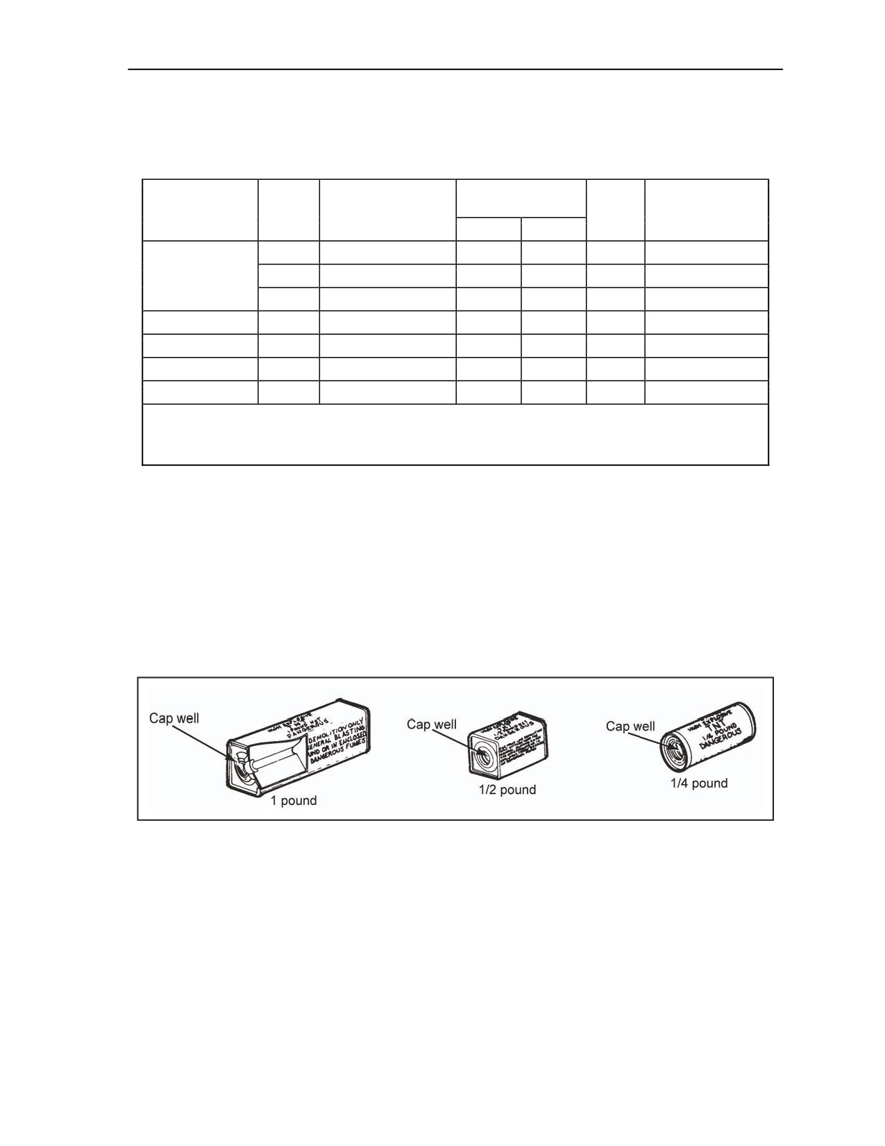
TRINITROTOLUENE BLOCK DEMOLITION CHARGE
1-14. TNT charges are discussed below. Discussed are the characteristics, uses, advantages, and limitations
of TNT charges.
CHARACTERISTICS
1-15. The TNT charges shown in Figure 1-1 are available in three sizes (Table 1-2). The 1/4-pound block
is issued in a cylindrical, waterproof, olive drab cardboard container. The 1/2-pound and 1-pound blocks
are available in similar rectangular containers. All of the three charges have metal ends with a threaded cap
well in one end.
Figure 1-1. TNT Block Demolition Charges
USES
1-16. TNT charges are effective for all types of demolition work, except for special steel-cutting charges.
However, the 1/4-pound charge is primarily for training purposes.
ADVANTAGES
1-17. TNT charges have a high detonating velocity. They are stable, relatively insensitive to shock or
friction, and are water resistant. They are conveniently sized, shaped, and packaged.
11 July 2007
FM 3-34.214
1-5
Chapter 1
LIMITATIONS
1-18. TNT charges cannot be molded and are difficult to use on irregularly shaped targets. TNT is not
recommended for use in closed spaces because one of the products of explosion is poisonous gases.
M112 BLOCK DEMOLITION CHARGE
1-19. M112 block demolition charges are discussed in the paragraph below. Discussed are the
characteristics, uses, advantages, and limitations of a M112 block demolition charge.
CHARACTERISTICS
1-20. An M112 charge consists of 1 1/4 pounds of composition C4 packed in an olive drab film container
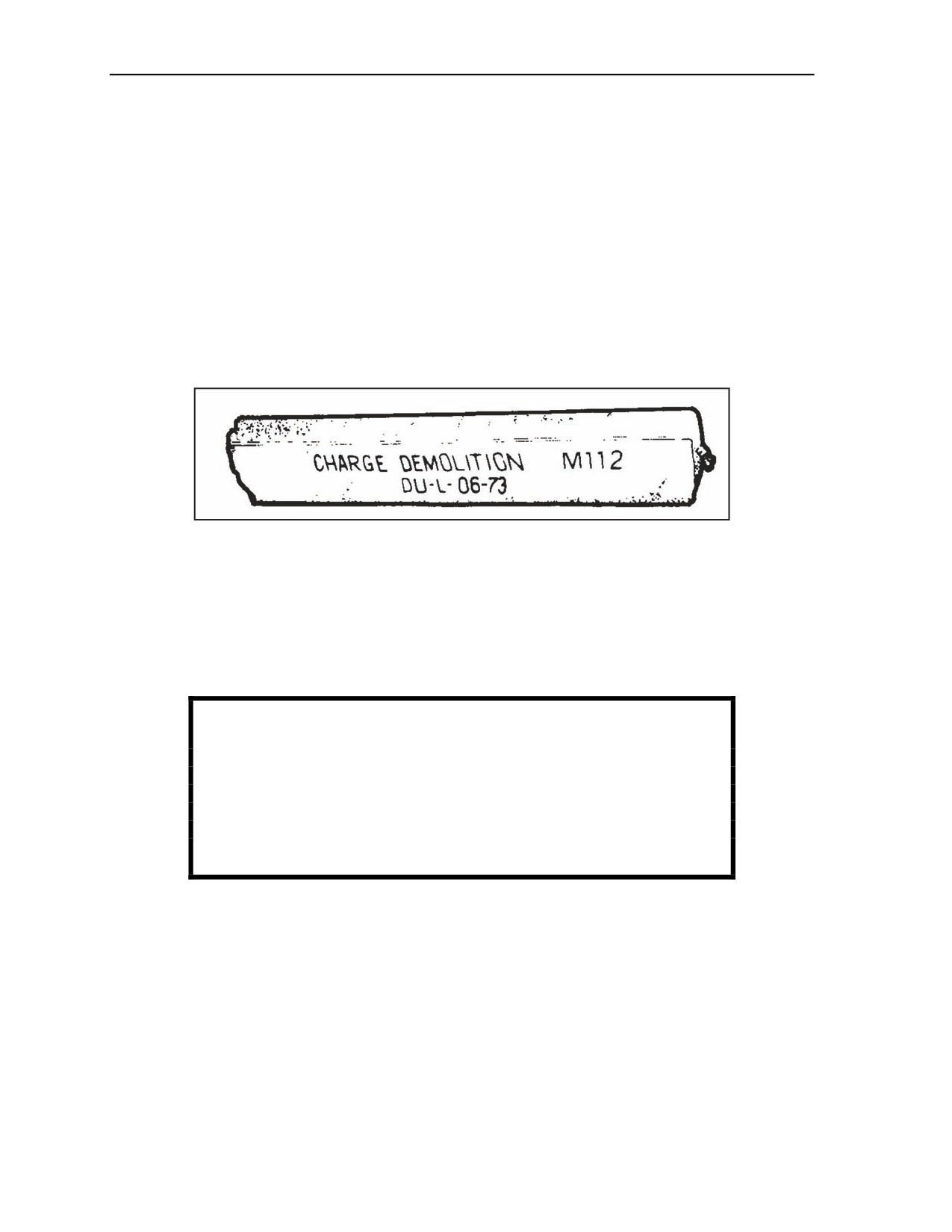
with a pressure-sensitive adhesive tape on one surface (Figure 1-2). A peelable paper cover protects the
tape. Table 1-2 lists additional characteristics of the M112 block.
Figure 1-2. M112 Block Demolition Charge
USES
1-21. The M112 charge is used primarily for cutting and breaching. Because of its high cutting effect and
its ability to be cut and shaped, the M112 charge is ideally suited for cutting irregularly shaped targets, such
as steel. The adhesive backing allows the charge to be placed on any relatively flat, clean, dry surface with
a temperature that is above the freezing point. The M112 charge is the primary block demolition charge
presently in use.
WARNING
Composition C4 explosive is poisonous and dangerous if chewed
or ingested; its detonation or burning produces poisonous fumes.
Cut all plastic explosives with a sharp, nonsparking steel knife on
a nonsparking surface. Shears should not be used. Failure to
comply could result in immediate personal injury or damage to
equipment.
ADVANTAGES
1-22. The M112 block demolition charge can be cut or molded to fit irregularly shaped targets. The color
of the wrapper helps camouflage the charge.
LIMITATIONS
1-23. The adhesive tape will not adhere to wet, dirty, rusty, or frozen surfaces. Molding the charge can
decrease its cutting effect.
1-6
FM 3-34.214
11 July 2007
Military Explosives
M186 ROLL DEMOLITION CHARGE
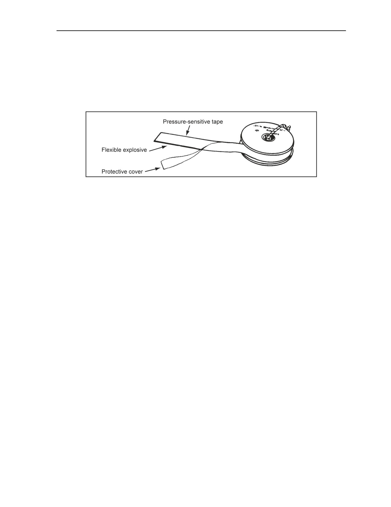
1-24. A M186 charge (Figure 1-3) is in roll form on a 50-foot plastic spool. Each foot of the roll provides
about 1/2 pound of explosive. Included with each roll are 15 M8 blasting cap holders and one canvas bag
with a carrying strap. Table 1-2, page 1-5, lists additional characteristics for the M186 charge. The M186
charge is adaptable for demolishing targets that require using flexible explosives in lengths longer than
12 inches. The M186 charge can be cut to the exact lengths desired. One limitation of the M186 charge is
that the adhesive backing will not adhere to wet, dirty, rusty, or frozen surfaces.
Figure 1-3. M186 Roll Demolition Charge
40-POUND, COMPOSITION H6 CRATERING CHARGE
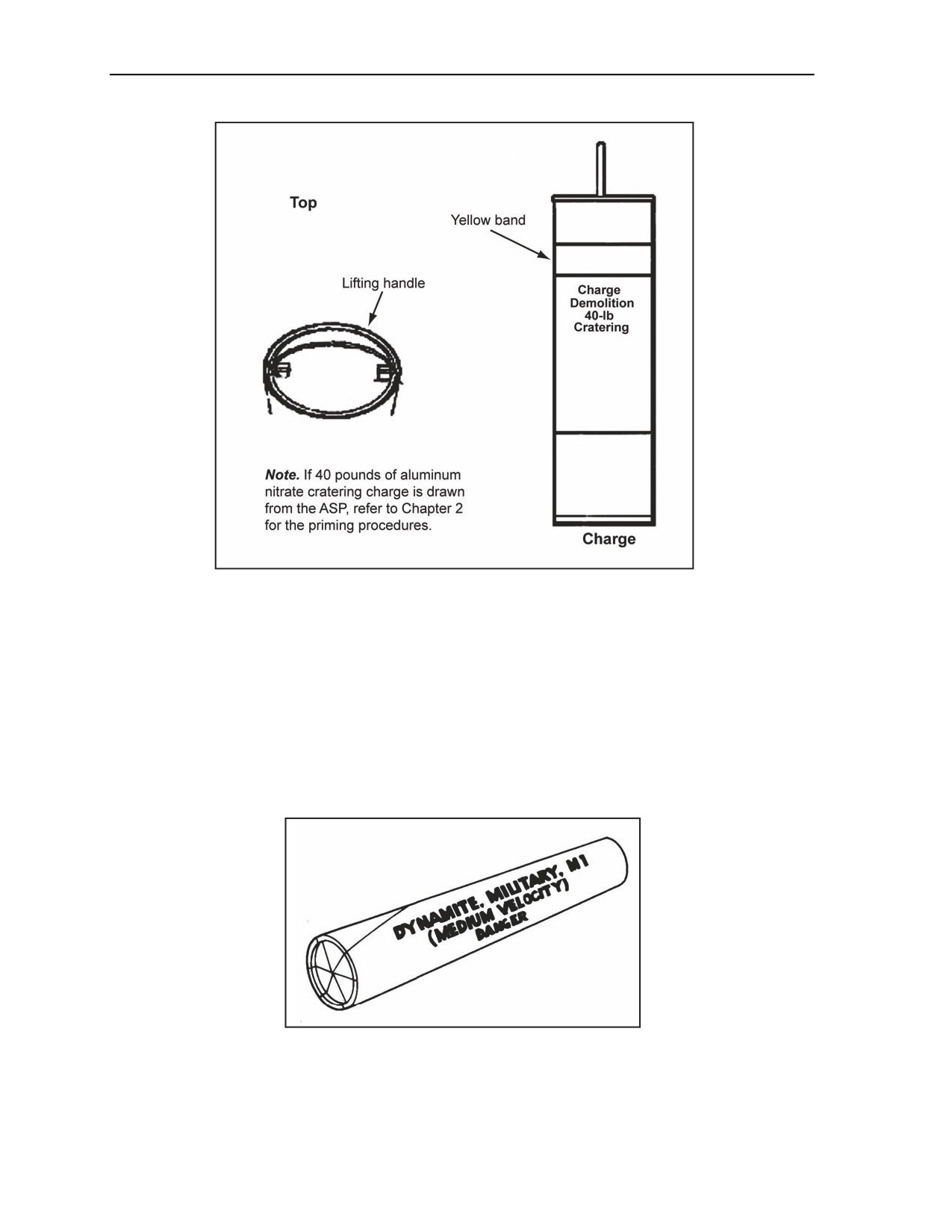
1-25. Figure 1-4, page 1-8, shows a composition H6 cratering charge. It is a watertight, cylindrical metal
container with 40 pounds of composition H6 explosive and has 0.43 pound of composition A5 explosive
booster positioned at the top. Priming instructions are printed on the side of the canister. There is a metal
ring (lifting handle) on the top of the container for lowering the charge into its hole. Table 1-2 lists
additional characteristics for the composition H6 charge. This charge is suitable for cratering and ditching
operations. Its primary use is as a cratering charge, but it is also effective for destroying buildings,
fortifications, and bridge abutments. The advantage of this charge is its size and shape, making it ideal for
cratering operations. It is inexpensive to produce compared to other explosives.
11 July 2007
FM 3-34.214
1-7
Chapter 1
Figure 1-4. 40-Pound, Composition H6 Cratering Charge
M1 MILITARY DYNAMITE
1-26. M1 military dynamite is discussed below. Discussed are the characteristics, uses, advantages, and
limitations of M1 military dynamite.
CHARACTERISTICS
1-27. M1 military dynamite is an RDX-based composite explosive containing no nitroglycerin
(Figure 1-5). M1 dynamite is packaged in 1/2-pound, paraffin-coated, cylindrical paper cartridges, which
have a nominal diameter of 1 1/4 inches and a nominal length of 8 inches. Table 1-2, page 1-4, lists
additional characteristics for M1 military dynamite.
Figure 1-5. M1 Military Dynamite
1-8
FM 3-34.214
11 July 2007
Military Explosives
USES
1-28. The primary use of M1 dynamite is for stump removal, military construction, quarrying, ditching,
and service demolition work. M1 is suitable for underwater demolitions.
ADVANTAGES
1-29. M1 dynamite will not freeze or perspire in storage. Its composition is not hygroscopic. Unlike
civilian dynamite containers, military shipping containers do not require turning during storage. M1
dynamite is safer to store, handle, and transport than 60 percent of commercial dynamite. Unless essential,
do not use civilian dynamite in combat areas.
LIMITATIONS
1-30. M1 dynamite is reliable underwater for only 24 hours. Because of its low sensitivity, sticks of
military dynamite should be packed well to ensure complete detonation of the charge. M1 dynamite is not
efficient as a cutting or breaching charge.
SHAPED DEMOLITION CHARGE
1-31. The shaped demolition charge used in military operations is a cylindrical block of HE. It has a
conical cavity in one end that directs the lining material of the cone into a narrow jet to penetrate materials
(Figure 1-6). This charge is not effective underwater, since any water in the conical cavity will prevent the
high-velocity jet from forming. To obtain maximum effectiveness, place the cavity at the specified standoff
distance from the target, and detonate the charge from the exact rear center using only the priming well that
is provided. Never dual-prime a shaped charge (a charge shaped so as to concentrate its explosive force in
a particular direction) (JP 1-02).
Figure 1-6. Shaped Demolition Charges
11 July 2007
FM 3-34.214
1-9

Chapter 1
CHARACTERISTICS
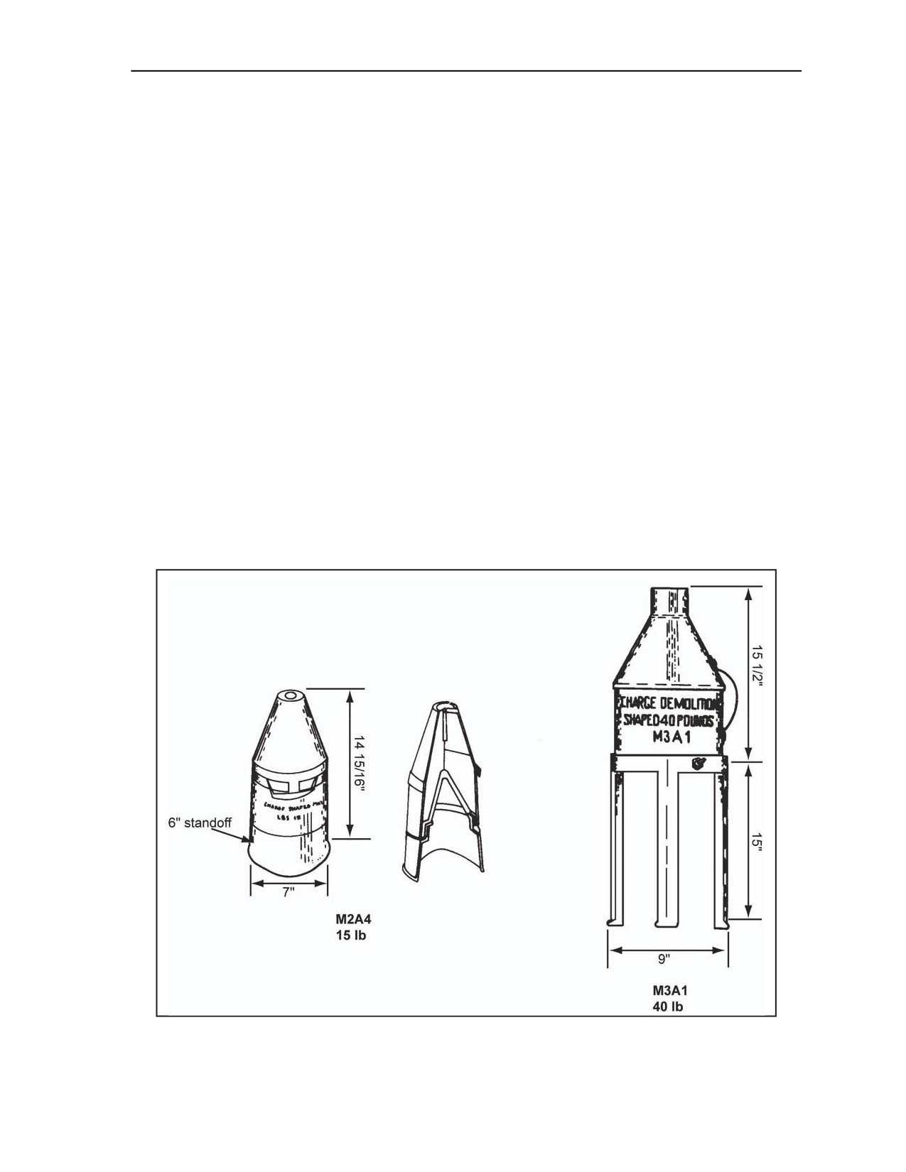
1-32. Following are the characteristics of the 15-pound M2A4 shaped demolition charge. Also discussed
are the characteristics of the 40-pound M3A1 shaped demolition charge.
15-Pound M2A4 Shaped Demolition Charge
1-33. An M2A4 charge contains a 0.11-pound booster of composition A3 and an 11.5 1/2-pound main
charge of composition B. It is packaged with three charges per wooden box (total weight is 65 pounds).
This charge has a moisture-resisting, molded-fiber container. A cylindrical fiber base slips onto the end of
the charge to provide a 6-inch standoff distance. The cavity liner is a cone of glass. The charge is 14 15/16
inches high and 7 inches in diameter, including the standoff. Table 1-3 lists the penetrating capabilities of
the M2A4 in various types of materials.
40-Pound M3A1 Shaped Demolition Charge
1-34. An M3A1 charge contains a 0.11-pound booster of composition A3 and a 29.5-pound main charge of
composition B. It is packaged with one charge per box (total weight is 65 pounds). The charge is in a metal
container, and the cone liner is made of metal. A metal tripod provides a 15-inch standoff distance. The
charge is 15 1/2 inches high and 9 inches in diameter, not including the standoff.
USES
1-35. The primary use of a shaped demolition charge is for boring holes in the earth, metal, masonry,
concrete, and paved and unpaved roads. Its effectiveness depends largely on its shape, composition, and
placement. Table 1-3, pages 1-11 and 1-12, lists the penetrating capabilities of various materials and the
proper standoff distances for these charges.
1-10
FM 3-34.214
11 July 2007

Military Explosives
Table 1-3. Characteristics of Boreholes Made By Shaped Charges
M2A4,
M3A1,
Material
Specifications
Shaped Charge*
Shaped Charge**
(15 lb)
(40 lb)
Penetration
12.00 in
At least 20.00 in
Armor plate
Average hole diameter
01.50 in
02.50 in
Maximum wall thickness
36.00 in
60.00 in
Penetration depth in thick walls
30.00 in
60.00 in
Reinforced concrete
Average hole diameter
02.75 in
03.50 in
Minimum hole diameter
02.00 in
02.00 in
Optimum standoff
42.00 in
60.00 in
Concrete pavement
Minimum penetration depth
44.00 in
71.00 in
(10 in with a 21-in
rock base course)
Maximum penetration depth
91.00 in
109.00 in
Minimum hole diameter
01.75 in
06.75 in
Optimum standoff
42.00 in
—
Concrete pavement
Minimum penetration depth
38.00 in
—
(3 in with a 24-in
rock base course)
Maximum penetration depth
90.00 in
—
Minimum hole diameter
03.75 in
—
Hole depth (30-in standoff)
72.00 in
—
Hole depth (42-in standoff)
60.00 in
—
Hole depth (50-in standoff)
—
72.00 in
Permafrost
Hole diameter (42-in standoff)
1.50 to 6.00 in
—
Hole diameter (50-in standoff)
—
05.00 to 08.00 in
Hole diameter (normal standoff)
04.00 to 30.00 in
07.00 to 30.00 in
Hole depth (42-in standoff)
07.00 ft
12.00 ft
Ice
Hole diameter (42-in standoff)
03.50 in
06.00 in
Hole depth (30-in standoff)
07.00 ft
—
Hole depth (48-in standoff)
—
07.00 ft
Soil
Hole diameter (30-in standoff)
07.00 in
—
Hole diameter (48-in standoff)
—
14.50 in
Graveled roads
Hole depth (30-inch standoff)
07.00 ft
—
Hole depth (48-in standoff)
—
09.00 ft
11 July 2007
FM 3-34.214
1-11
Chapter 1
Table 1-3. Characteristics of Boreholes Made By Shaped Charges
M2A4,
M3A1,
Material
Specifications
Shaped Charge*
Shaped Charge**
(15 lb)
(40 lb)
Hole diameter (30-in standoff)
07.00 in
—
Hole diameter (48-in standoff)
—
07.00 in
*A dash in the column indicates that an M3A1, shaped charged is required.
**A dash in the column indicates that an M2A4, shaped charge is enough.
SPECIAL PRECAUTIONS
1-36. To achieve the maximum effectiveness of shaped charges—
Center the charge over the target point.
Align the axis of the charge with the direction of the desired hole.
Use the pedestal to obtain the proper standoff distance.
Suspend the charge at the proper height on pickets or tripods if the pedestal does not provide the
proper standoff distance.
Remove any obstruction in the cavity liner or between the charge and the target.
M1A2 BANGALORE TORPEDO DEMOLITION KIT
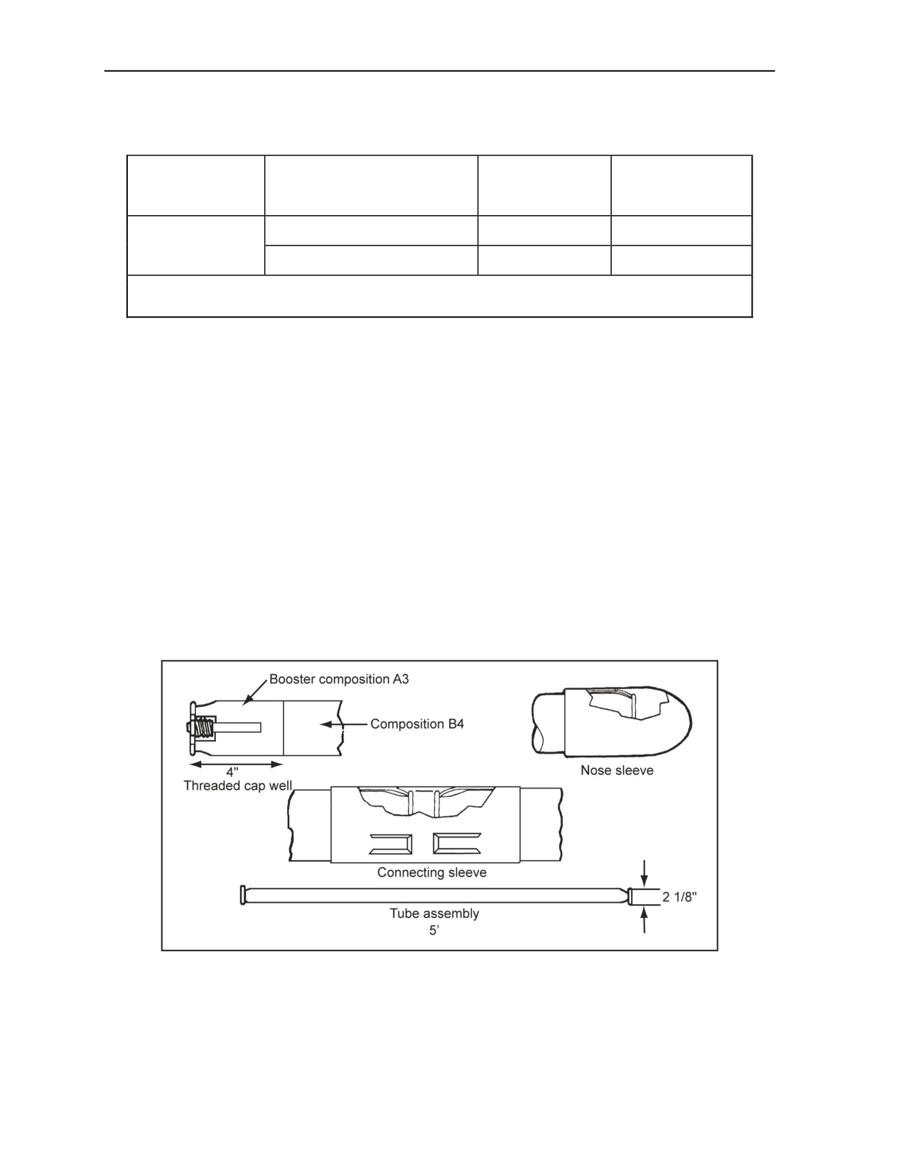
1-37. Each demolition kit (the demolition tool kit complete with explosives) (JP 1-02) consists of 10 tube
assemblies, 10 connecting sleeves, and 1 nose sleeve. The tube assemblies or torpedoes are steel tubes
5 feet long and 2 1/8 inches in diameter, grooved and capped at each end (Figure 1-7). The torpedoes have
a 4-inch composition A3 booster (1/2 pound each) at both ends of each 5-foot section. The main explosive
charge is 10 1/2 pounds of composition B4. The kit is packaged in a 60 3/4- by 13 3/4- by 4 9/16-inch
wooden box and weighs 211 pounds.
Figure 1-7. M1A2 or M1A3 Bangalore Torpedo
M1A3 BANGALORE TORPEDO DEMOLITION KIT
1-38. The M1A3 bangalore torpedo demolition kit is discussed below. Discussed are the characteristics,
uses, advantages, and limitations of the demolition kit.
1-12
FM 3-34.214
11 July 2007

Military Explosives
CHARACTERISTICS
1-39. Each kit consists of
10 tube assemblies, connecting sleeves, and two nose sleeves. The tube
assemblies, or torpedoes, are steel tubes 2 1/2 feet long and 2 1/8 inches in diameter, grooved and capped at
each end (Figure 1-7). The torpedoes have a 4-inch composition A3 booster (1/2 pound each) at both ends
of each 2 1/2 foot section. The main explosive charge is 5 pounds of composition B4.
USES
1-40. The primary use of the torpedo is for clearing paths through wire obstacles and heavy undergrowth.
It will clear a 3- to 4-yard-wide path through wire obstacles.
DANGER
The bangalore torpedo may detonate a live mine when being
placed. To aid in preventing this, attach the nose sleeve to a
fabricated dummy section (about the same dimensions as a
single bangalore section), and place the dummy section onto the
front end of the torpedo. Failure to comply may cause death or
permanent injury.
ASSEMBLY
1-41. All sections of the torpedo have threaded cap wells at each end. To assemble two or more sections,
press a nose sleeve onto one end of one tube, and then connect successive tubes (using the connecting
sleeves provided) until you have the desired length. The connecting sleeves make rigid joints. The nose
sleeve allows the user to push the torpedo through entanglements and across the ground.
DANGER
Do not modify the bangalore torpedo. Cutting the bangalore or
making any other modification could cause the device to explode.
Failure to comply may cause death or permanent injury.
M4 SELECTABLE, LIGHTWEIGHT ATTACK MUNITION
1-42. The M4 selectable, lightweight attack munition (SLAM) is discussed below. Discussed are the
characteristics, uses, advantages, and limitations of the M4 SLAM.
CHARACTERISTICS
1-43. The M4 SLAM (Figure 1-8, page 1-14) (Table 1-4, page 1-14) is olive green in color with a black
liner and no labels, bands, or other distinguishing marks. When the M4 SLAM is employed, the operator
selects the operating mode and length of time that it will function to defeat selected targets using an
explosively formed penetrator (EFP) warhead. During bottom- and side-attack modes, the M4 SLAM will
self-destruct if the selected time expires before a vehicle detonates it. With the time demolition mode, the
M4 SLAM will detonate after the selected time delay has expired. Other versions of this munition are the
M2 and M3 special operations forces (SOF) SLAM. The M2 version will self-disarm and will go into dud
status (cannot be rearmed). The M3 version can only be initiated by command detonating the unit. The
packaging protects the M4 SLAM so it will function with no degradation attributable to packaging after up
to 2 years with outside, unprotected, uncontrolled storage, and 20 years protected controlled storage. No
new or unique storage facilities are anticipated for the M4 SLAM munition. Individual M4 SLAMs are
contained in their own reusable environmental protective packs (REPPs) that consist of two-piece plastic
containers consisting of a top and bottom half held together with four clips. There are eight REPPs, eight
11 July 2007
FM 3-34.214
1-13

Chapter 1
carrying straps, and eight leg straps in each PA19 container. The packaged ammunition is palletized on a
wooden pallet. The pallet consists of 2 PA19 containers per wire-bound box and 27 wire-bound boxes for a
total of 54 PA19 containers.
Figure 1-8. M4 SLAM
Table 1-4. M4 SLAM Characteristics
Pallet Dimensions
Length
45 1/2 in
Width
35 13/16 in
Height
43 15/16 in
Weight (loaded)
2,016 lb
M4 SLAM Weights and Dimensions
Weight
2.2 lb
Length
5.15 in
Width
3.5 in
Depth
2.15 in
USES
1-44. The M4 SLAM is a small antidisturbance and tamper resistant, multipurpose munition designed to be
portable, hand emplaced, and used against lightly armored infantry vehicles, parked aircraft, wheeled or
tracked support vehicles, and ammunition or petroleum, oils, and lubricants (POL) storage sites.
DANGER
Never approach the M4 SLAM for any reason. Once armed, the M4
SLAM will detonate. Failure to comply may cause death or
permanent injury.
1-14
FM 3-34.214
11 July 2007

Military Explosives
DANGER
During live-fire training, an initiating system
(such as wire,
detonating cord, or shock tube) must be laid out to a safe location
away from the SLAM before arming the SLAM so that the SLAM
can be safely initiated in case of an electronic shutdown or a dud
(an explosive munition which has not been armed as intended or
which has failed to explode after being armed) (JP 1-02). Failure
to comply may cause death or permanent injury.
ADVANTAGES
1-45. The M4 SLAM can be used day or night and during all weather conditions. The four operating
modes include—
Bottom-attack mode. See Figure 1-9. The M4 SLAM has a built-in magnetic sensor that allows
it to be used as a magnetic-influenced munition against trucks or lightly armored vehicles. The
magnetic sensor is designed to trigger detonation when it senses a vehicle overpass. It can be
concealed along trails and roads where target vehicles operate and can be camouflaged using
light overburden, dry leaves, and grass without affecting EFP performance as long as debris does
not extend beyond the depth of the EFP cup level. The M4 SLAM self-destructs if the selected
time expires before a passing vehicle detonates the munition.
Figure 1-9. Bottom-Attack Mode
Side-attack mode. See Figure 1-10, page 1-16. The M4 SLAM is equipped with a passive
infrared (PIR) sensor specifically developed for the side-attack mode. The sensor detects trucks
and lightly armored vehicles by sensing a change in background temperatures when the vehicles
cross in front of the sensor port. The sensor is directional and aligned with the EFP. The M4
SLAM self-destructs if the selected time expires before being detonated by a passing vehicle.
11 July 2007
FM 3-34.214
1-15

Chapter 1
Figure 1-10. Side-Attack Mode
Timed-detonation mode. See Figure 1-11. The M4 SLAM will detonate at the end of a selected
time delay. In this mode, the magnetic sensor and PIR sensor are not operable.
Figure 1-11. Timed-Demolition Mode
Command-detonation mode. The command-denotation mode (Figure 1-12) provides manual
warhead initiation using M6, M7, or MDI blasting caps and boosters with a M1A4 priming
adapter. This capability bypasses the M4 SLAM fuze (a device which initiates an explosive
train) (FM 1-02) and safe-and-arm (S&A) assembly.
Figure 1-12. Command-Detonation Mode
1-46. The M4 SLAM has the following two secondary operating features:
Antidisturbance. The M4 SLAM will detonate if it is moved or handled after arming.
Antidisturbance is active for the bottom- and side-attack modes only.
Antitamper. The M4 SLAM will detonate if any attempt is made to change the selector switch
after arming. This mode is active for the bottom- and side-attack modes only.
1-16
FM 3-34.214
11 July 2007

Military Explosives
LIMITATIONS
1-47. The M4 SLAM warhead performance may be affected by heavy overburden. If the M4 SLAM needs
to be hidden from view, a light layer of grass or leaves can be used to cover it. To defeat the target, the EFP
needs a minimum of 5 inches from the point of emplacement to the target to form properly.
M300 FIGHTING POSITION EXCAVATOR AND M301 FIGHTING
POSITION EXCAVATOR RELOAD KIT
1-48. The M300 FPE and M301 FPE reload kit are discussed below. Discussed are the characteristics,
uses, and emplacement of the M300 FPE and M301 FPE reload kit.
CHARACTERISTICS
1-49. Each M300 FPE kit (Figure 1-13) comes in a canvas carrying bag and contains a four-piece bucket
auger, an empty sandbag, two binary explosive containers (each with a booster assembly permanently
installed), a blasting cap assembly with an M9 holder attached, and an M81 fuse igniter. The binary charges
consist of two nonexplosive components that must be mixed together to form an explosive compound. The
booster assemblies that prime the charges consist of a booster (containing only secondary explosive),
crimped to a length of low-strength detonating cord (a waterproof, flexible fabric tube containing a HE
designed to transmit the detonation wave) (JP 1-02) to allow charge emplacement belowground. The
blasting cap assembly consists of a military-type blasting cap crimped to a 25-meter length of shock tube.
The auger is used to dig holes for emplacing the charges and for measuring hole depth and separation. The
M301 FPE reload kit provides additional explosives and sandbags for creating two additional two-man
fighting positions. It is packaged in the same FPE canvas carrying bag. The operator must use the auger
from an FPE kit to dig holes for emplacing the explosive charges of the reload kit.
Figure 1-13. M300 FPE Kit
11 July 2007
FM 3-34.214
1-17

Chapter 1
USES
1-50. The FPE system is used to loosen the soil. The time it takes to dig a two-man fighting position is
reduced by the FPE system.
EMPLACEMENT
1-51. The dimensions of a two-man fighting position (6 feet by 2 feet) are laid out on the ground. A bucket
auger should be used to dig a hole one foot in from the end of the outline. The length of the bucket auger is
used as a measuring device. When the handle of the auger is 1 to 2 inches above the ground hole, the depth
is about 40 inches. The length of the bucket auger is used to measure the distance to a second hole location.
A second hole is dug to the same depth as the first.
1-52. The protective cap is then unscrewed and removed from the end of the liquid tube. The liquid tube
should be unscrewed and separated from the powder tube. The liquid tube should be held in one hand with
the seal facing up to prevent spillage of the liquid component during assembly. The sealed end of the
powder tube should be aligned over the liquid tube, then the two tubes should be screwed together. The
tubes should be securely seated and the explosive container shook vigorously for one minute to ensure
thorough mixing. After unwinding the length of the low-strength detonating cord from the spool on the
powder containers, one container is lowered into each hole while the low-strength detonating cord is held
out of the hole. The charges should be tamped with loose dirt.
1-53. Low-strength detonating cord is connected to the blasting cap assembly using the M9 holder attached
to the blasting cap. The low-strength detonating cord is spread between the primed charge and the M9
holder of the transmission line. Avoid conditions where cords are running alongside or twisted with other
cord to minimize crossover of any low-strength detonating cord.
1-54. The shock tube is run to a sheltered position about 25 meters from the buried charges. A square cut is
made at the end of the shock tube assembly and an M81 fuse igniter is attached. The safety pin is removed
from the M81 and the pull ring is pulled sharply to initiate the explosive train.
SECTION III - DEMOLITION ACCESSORIES
M700 TIME-BLASTING FUSE
1-55. A time-blasting fuse transmits a delayed spit of flame to a nonelectric blasting cap. The delay allows
a Soldier to initiate a charge and get to a safe distance before the explosion. The two types of fuses are the
M700 time fuse and the safety fuse. Except for SOF, the M14 and M18 modernized demolition initiator
(MDI) will replace the M700 time fuse. The M700 time fuse is a dark green cord, 0.2 inch in diameter, with
a plastic cover (Figure 1-14). It burns at a rate of 40 seconds per foot. However, test the burning rate as
outlined in Chapter 2. Depending on the date of manufacture, the cover may be smooth or have single
yellow bands around the outside at 12- or 18-inch intervals and double yellow bands at 60- or 90-inch
intervals. These bands accommodate hasty measuring. The outside covering becomes brittle and cracks
easily in arctic temperatures. The M700 time fuse is packaged in 50-foot coils, two coils per package, five
packages per sealed container, and eight containers (4,000 feet) per wooden box (30 1/8 by 15 1/8 by
14 7/8 inches). The total package weighs 94 pounds.
1-18
FM 3-34.214
11 July 2007
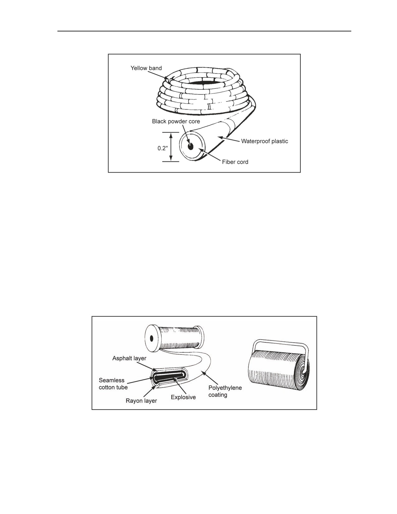
Military Explosives
Figure 1-14. M700 Time Fuse
DETONATING CORD
1-56. The American, British, Canadian, and Australian
(ABCA) standardization program recognizes
Type 1 detonating cord as the standard detonating cord. The paragraphs below discuss the characteristics,
uses, and precautions of detonating cord.
CHARACTERISTICS
1-57. Detonating cord (Figure 1-15) consists of a core of HE (6.4 pounds of pentaerythrite tetranitrate
[PETN] per 1,000 feet) wrapped in a reinforced and waterproof, olive drab plastic coating. This detonating
cord is about 0.2 inch in diameter, weighs about 18 pounds per 1,000 feet, and has a breaking strength of
175 pounds. Detonating cord is functional in the same temperature range as plastic explosive, although the
cover becomes brittle at lower temperatures. Moisture can penetrate the explosive filling to a maximum
distance of 6 inches from any cut or break in the coating. Water-soaked detonating cord will detonate if
there is a dry end to allow initiation. A 6-inch tail should be left when making connections or when priming
charges.
Figure 1-15. Detonating Cord
USES
1-58. Detonating cord can be used to prime and detonate single or multiple explosive charges
simultaneously. Chapter 2 explains the use of detonating cord for these purposes.
11 July 2007
FM 3-34.214
1-19

Chapter 1
PRECAUTIONS
1-59. The end of the detonating cord is sealed with a waterproof sealant when used to fire (1. The
command given to discharge a weapon(s). 2. To detonate the main explosive charge by means of a firing
system) (JP 1-02) (FM 1-02) underwater charges or when charges are left in place several hours before
firing. If left for no longer than 24 hours, a 6-inch overlap will protect the remainder of the line from
moisture. Kinks, sharp bends in priming, or unintended crossovers should be avoided because they may
interrupt or change the direction of detonation and cause misfires.
Note. To avoid internal cracking, do not step on the detonating cord.
BLASTING CAPS
1-60. Blasting caps are for detonating HEs. The two types of blasting caps are electric and nonelectric.
They are designed for insertion into the cap wells and are the detonating element in certain firing systems
and devices. Blasting caps are rated in power according to the size of their main charge. Number 6 and 8
commercial blasting caps are for detonating sensitive explosives, such as commercial dynamite and tetryl.
Special military blasting caps (M6 electric and M7 nonelectric) ensure positive detonation of less sensitive
military explosives. Their main charge is about double that of commercial Number 8 blasting caps. Never
carry blasting caps loose or in uniform pockets where they are subject to shock. Properly separate the
blasting caps. Blasting caps should never be stored with other explosives. Blasting caps and other
explosives should not be carried in the same vehicle except in an emergency (see Chapter 6). See TM 43
0001-38 for additional information on blasting caps.
WARNING
Handle military and commercial blasting caps carefully; both are
extremely sensitive and may explode if handled improperly. Do
not tamper with blasting caps. Protect them from shock and
extreme heat. Failure to comply could result in immediate
personal injury or damage to equipment.
ELECTRIC
1-61. Electric blasting caps are used for command detonation or when a source of electricity (such as a
blasting machine or a battery) is available. Both military and commercial caps may be used. Military caps
(Figure 1-16) operate instantaneously. Commercial caps may operate instantaneously or have a delay
feature. The delay time of commercial caps for military applications ranges from 1 to 1.53 seconds. Electric
caps have lead wires of various lengths. The most common lead length is 12 feet. Electric caps require
1.5 amperes of power to initiate. The standard-issue cap is the M6 special electric blasting cap.
1-20
FM 3-34.214
11 July 2007
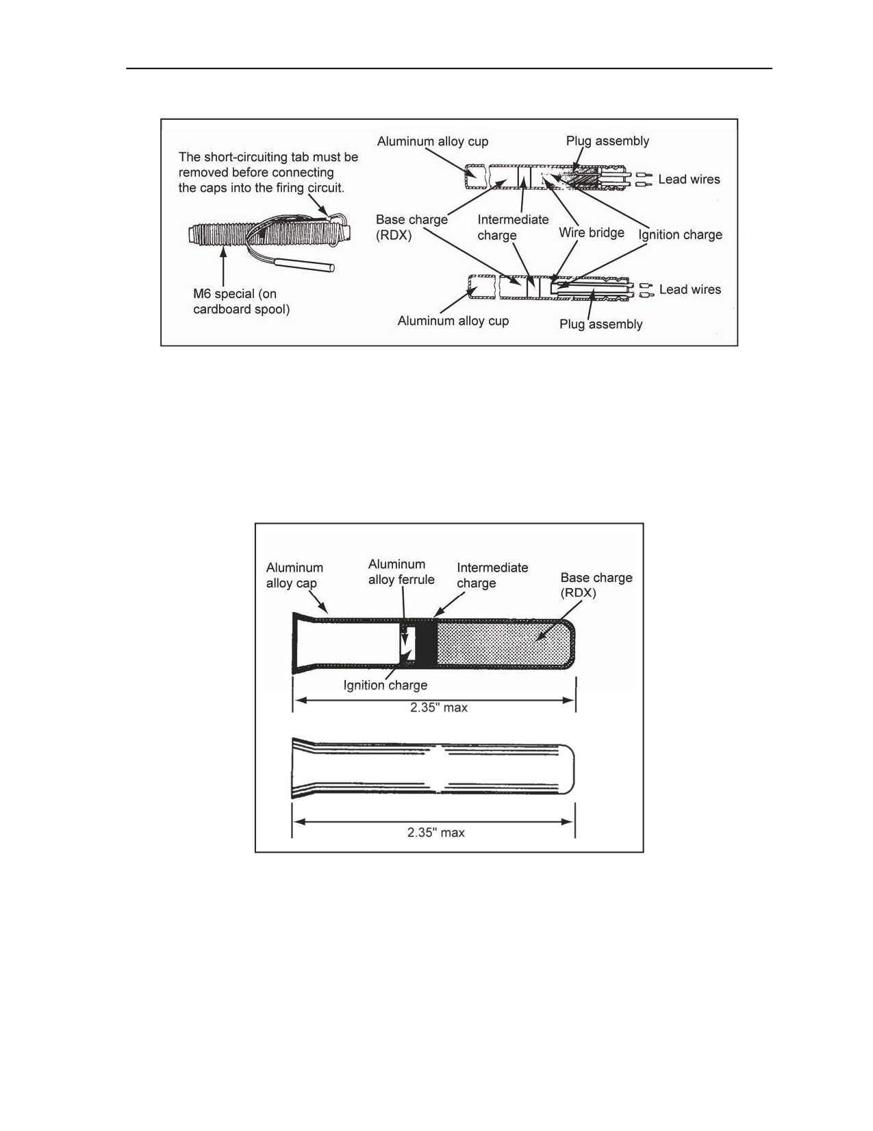
Military Explosives
Figure 1-16. Electric Blasting Caps
NONELECTRIC
1-62. Nonelectric blasting caps are initiated with a time-blasting fuse, a firing device, or detonating cords
(Figure 1-17). Use of nonelectric blasting caps to prime underwater charges should be avoided because the
caps are hard to waterproof. If necessary, waterproof nonelectric blasting caps with a sealing compound.
The M7 nonelectric blasting cap is the standard issue. The open end of the M7 nonelectric blasting cap is
flared to allow easy insertion of detonating cord or a time fuse. TM 43-0001-38 gives additional
information on blasting caps.
Figure 1-17. Nonelectric Blasting Caps
BOOSTERS
1-63. A booster is similar in appearance to a blasting cap but contains no primary explosive. The secondary
explosive in the booster contains enough energy to initiate military explosives. Boosters are precrimped to
low-strength detonating cord on the M151- and the M152-MDI components (Figure 1-18, page 1-22). The
boosters provide a means to prime buried charges by following priming methods for standard military
explosives.
11 July 2007
FM 3-34.214
1-21

Chapter 1
Figure 1-18. Booster
NONELECTRIC BLASTING CAPS PRECRIMPED TO MODERNIZED
DEMOLITION INITIATOR COMPONENTS
1-64. The MDI system introduces precrimped blasting caps onto premature lengths of shock tube and time
fuse with an environmental seal at the other end. The MDI provides the following enhancements to
conducting demolition operations:
Provides a nonelectric means of command initiation that is not sensitive to effects of overhead
power transmission lines, static electricity, radio transmissions, or effects of electromagnetic
pulse (EMP).
Provides packaging configurations that permit transportation of precrimped MDI blasting caps
on one vehicle at a less stringent hazard classification than individual blasting caps.
Provides the user with a preset burn time in 1-minute increments, but allows the Soldier to
conduct a more accurate burn rate.
Eliminates blasting cap crimping operations.
Provides detonating cord clips or holders on shock tube items for making connections to either
branchlines or ring mains.
Provides splicing tubes on spooled shock tube items for making repairs.
Introduces low-strength detonating cord (5 to 7.5 grams of explosive per foot) with precrimped
boosters to provide a capability to preprime charges for emplacement aboveground or
belowground.
Eliminates electrical initiation devices and supporting equipment requirements from demolition
kits.
BLASTING CAP PROTECTORS
1-65. Foam cylinders should be installed onto the high-strength blasting cap or booster of an MDI
component after removal from original packaging. The protector cushions the blasting cap or booster if
inadvertently struck by a hard object during handling. Soon foam cylinders will be included as part of the
standard packaging for MDI high-strength blasting caps and boosters.
M1A4 PRIMING ADAPTER
1-66. An M1A4 is a plastic, hexagonal-shaped device, threaded to fit threaded cap wells. The shoulder
inside the threaded end will allow a time-blasting fuse and detonating cord to pass, but the shoulder is too
small to pass a military blasting cap. To accommodate electric blasting caps, the adapter has a lengthwise
slot that permits blasting cap lead wires to be installed into the adapter quickly and easily (Figure 1-19).
M1A5 PRIMING ADAPTER
1-67. An M1A5 is a plastic, hexagonal-shaped device, threaded to fit threaded cap wells. The shoulder
inside the threaded end will allow a time-blasting fuse, detonating cord, or shock tube to pass, but the
shoulder is too small to pass a military blasting cap. To accommodate electric blasting caps or shock tube,
the adapter has a lengthwise slot that permits blasting cap lead wires or a shock tube to be installed in the
adapter quickly and easily (Figure 1-19).
1-22
FM 3-34.214
11 July 2007
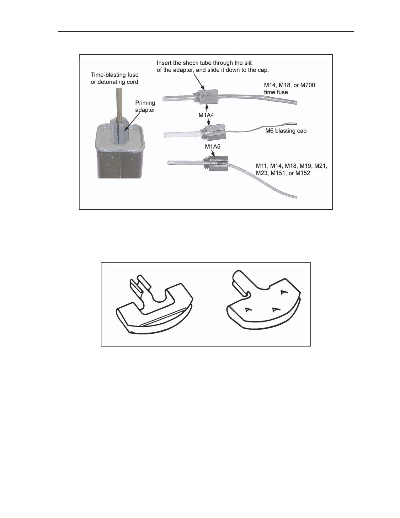
Military Explosives
Figure 1-19. M1A4 and M1A5 Priming Adapters
M8 BLASTING CAP HOLDER
1-68. An M8 is a metal clip designed to attach a blasting cap to a sheet explosive (Figure 1-20). These clips
are supplied with M186 charges. The M8 is available as a separate-issue item in quantities of 4,000.
Figure 1-20. M8 Blasting Cap Holder
M1 DETONATING CORD CLIP
1-69. An M1 clip is a device for holding two strands of detonating cord together, either parallel or at right
angles (Figure 1-21, Diagram 1 [page 1-24]). Using these clips is faster and more efficient than using knots.
Knots, if left for extended periods, may loosen and fail to function properly.
BRANCHLINES
1-70. Detonating cord branchlines are connected by passing them through the trough of the M1 clip and
through the hole in the tongue of the clip. Next, the ring or line main should be placed into the tongue of
the clip so that it crosses over the branchline at a 90° angle, and the crossover is held secure by the tongue.
It may be necessary to bend or form the tongue while doing this (Figure 1-21, Diagram 2).
11 July 2007
FM 3-34.214
1-23
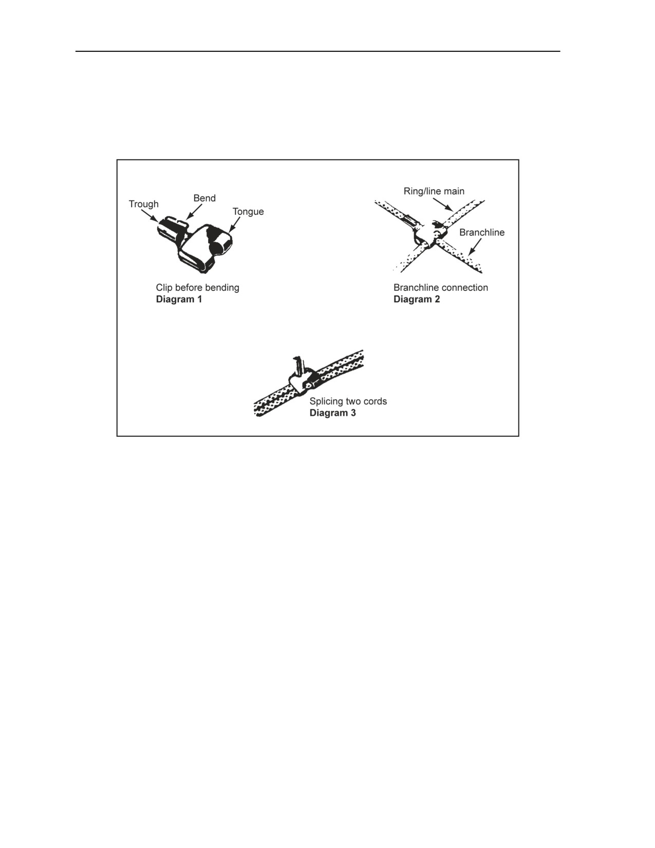
Chapter 1
SPLICES
1-71. The ends of the detonating cords are spliced by first overlapping them about 12 inches. Each loose
end is secured to the other cord by using a clip. The tongues of the clips are bent firmly over both strands.
The connection is made stronger by bending the trough end of the clip back over the tongue (Figure 1-21,
Diagram 3).
Figure 1-21. M1 Detonating Cord Clip
M1 ADHESIVE PASTE
1-72. M1 adhesive paste is a sticky, putty-like substance that is used to attach charges to flat, overhead, or
vertical surfaces. Adhesive paste is useful for holding charges while tying them in place or, under some
conditions, for holding the explosive to a target without ties. This paste does not adhere satisfactorily to
dirty, dusty, wet, or oily surfaces. M1 adhesive paste becomes useless when softened by water.
PRESSURE-SENSITIVE ADHESIVE TAPE
1-73. This tape is replacing the M1 adhesive paste. The tape has better holding properties and it is easily
and quickly applied. This tape is coated on both sides with pressure-sensitive adhesive and no solvent or
heat is required to apply. It is available in 2-inch-wide rolls, 72 yards long. This tape should be used to hold
charges effectively to dry, clean wood, steel, or concrete. This tape does not adhere to dirty, wet, oily, or
frozen surfaces.
WATERPROOF SEALING COMPOUND
1-74. This sealant is for waterproofing connections between time-blasting fuses or detonating cords and
nonelectric blasting caps. The sealing compound will not make a permanent waterproof seal. Since this
sealant is not permanent, underwater demolitions should be fired as soon as possible after placing them.
1-24
FM 3-34.214
11 July 2007
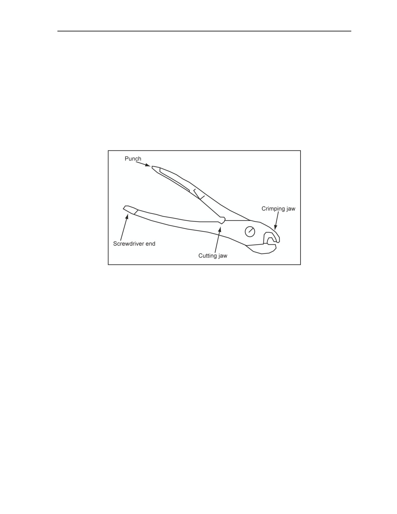
Military Explosives
M2 CAP CRIMPER
1-75. An M2 cap crimper (Figure 1-22) is used for squeezing the shell of a nonelectric blasting cap around
a time-blasting fuse, standard coupling base, or detonating cord. Crimp the shell securely to keep the fuse,
base, or cord from being pulled off but not so tightly that it interferes with the operation of the initiating
device. A stop on the handle helps to limit the amount of crimp applied. The M2 crimper forms a water-
resistant groove completely around the blasting cap. A sealing compound is applied to the crimped end of
the blasting cap to waterproof it. The cutting jaw, located on the leg, is shaped and sharpened for cutting
fuses and detonating cords. One leg of the handle is pointed for punching cap wells in explosive materials.
The other leg has a screwdriver end. Cap crimpers are made of a soft, nonsparking metal that conducts
electricity. Do not use cap crimpers as pliers because such use damages the crimping surface. The crimp
hole should be round (not elongated), and the cutting jaws should not be jagged. The cutting jaws should be
kept clean, and they should be used only for cutting fuses and detonating cords.
Figure 1-22. M2 Cap Crimper
M51 BLASTING CAP TEST SET
1-76. The paragraphs below discuss the M51 blasting cap test set. Discussed are the characteristics, uses,
and maintenance of the test set.
CHARACTERISTICS
1-77. The M51 is a self-contained unit with a magneto-type impulse generator, an indicator lamp, a handle
to activate the generator, and two binding posts for attaching firing leads. The test set is waterproof and
capable of operating at temperatures as low as 40°F (Figure 1-23, page 1-26).
11 July 2007
FM 3-34.214
1-25
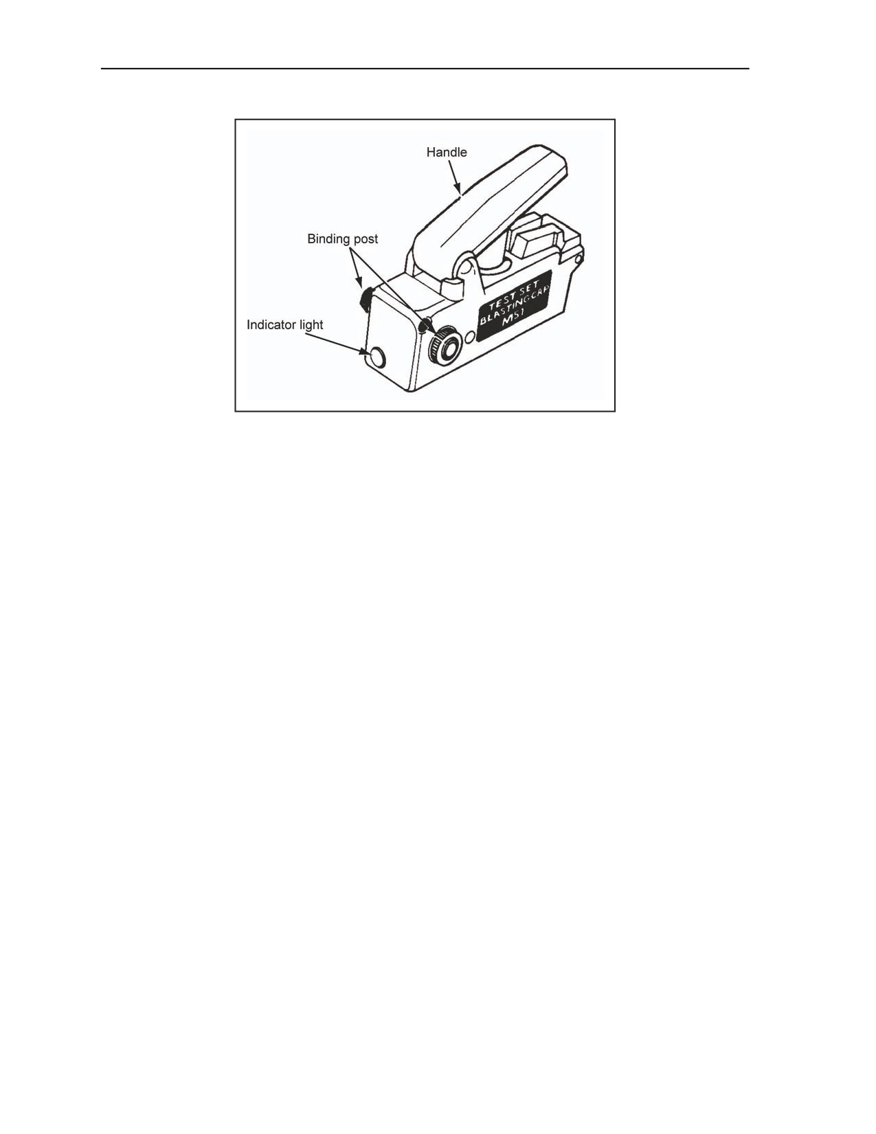
Chapter 1
Figure 1-23. M51 Blasting Cap Test Set
USES
1-78. The continuity of the firing wire, blasting cap, and firing circuit (in land operations, an electrical
circuit and/or pyrotechnic loop designed to detonate connected charges from a firing point [the definition
was shortened, and the complete definition is printed in the glossary]) (JP 1-02) should be checked by
connecting the leads to the test set binding posts and then by depressing the handle sharply. If there is a
continuous (intact) circuit, even one created by a short circuit, the indicator lamp will flash. When the
circuit is open, the indicator lamp will not flash.
MAINTENANCE
1-79. The test set should be handled carefully and kept dry to ensure optimum use. Before using, ensure
that the test set is operating properly by using the following steps:
Step 1. Hold a piece of bare wire or the legs of the M2 crimpers across the binding posts.
Step 2. Depress the handle sharply while watching the indicator lamp (lamp should flash).
Step 3. Remove the bare wire or crimper legs from the binding posts.
Step 4. Depress the handle sharply while watching the indicator lamp (lamp should not flash).
Both tests should be performed to ensure that the test set is operating properly.
BLASTING MACHINES
1-80. Blasting machines provide the electric impulse needed to initiate electric blasting cap operations.
When operated, the M32, M34, and CD450-4J models use an alternator and a capacitor to energize the
circuit.
M34, 50-CAP BLASTING MACHINE
1-81. This small, lightweight machine produces adequate current to initiate 50 electrical caps that are
connected in a series (Figure 1-24). It has a black band around the base and a reinforced-steel actuating
handle. The M34 can be tested and operated using the following steps:
Step 1. Check the machine for proper operation. This is done by releasing the blasting machine
handle by rotating the retaining ring downward while pushing in on the handle (handle should
automatically spring outward from the body of the machine).
1-26
FM 3-34.214
11 July 2007
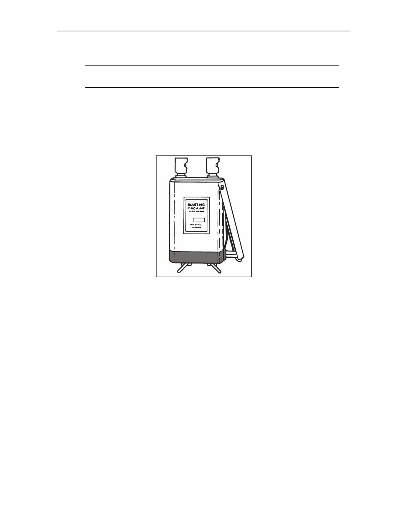
Military Explosives
Step 2. Activate the machine by depressing the handle rapidly three or four times until the neon
indicator lamp flashes.
Note. The lamp is located between the wire terminal posts and cannot be seen until it flashes,
since it is covered by green plastic.
Step 3. Insert the firing wire leads into the terminals by pushing down on each terminal post and
inserting the leads into the metal jaws.
Step 4. Hold the machine upright (terminals up) in either hand so that the plunger end of the
handle rests in the base of the palm and the fingers grasp the body of the machine. Make sure to
hold the machine correctly since the handles are easily broken.
Step 5. Squeeze the handle sharply several times until the charge fires (normally, no more than
three or four squeezes are required).
Figure 1-24. M34 Blasting Machine
CD450-4J BLASTING MACHINE
1-82. The CD450-4J blasting machine is discussed below. Discussed are the operational test and general
operating procedures for the machine.
Operational Test
1-83. An operational test should be conducted on the CD450-4J (Figure 1-25, page 1-28). This test should
be conducted as follows:
Step 1. Depress the charge switch and hold it down. The READY-TO-FIRE indicator should
light after 1 to 5 seconds and remain lit as long as the charge switch is held down.
Step 2. Continue holding the charge switch down until the READY-TO-FIRE indicator lights,
then wait at least 2 seconds and then depress the FIRE switch. Continue holding both switches
down for 3 seconds. Verify that the—
READY-TO-FIRE indicator remains lit for about 1/4 second after the FIRE switch is
depressed.
READY-TO-FIRE indicator is unlit after performing the step above.
Release both switches after observing the steps above. The blasting machine should be secured.
11 July 2007
FM 3-34.214
1-27
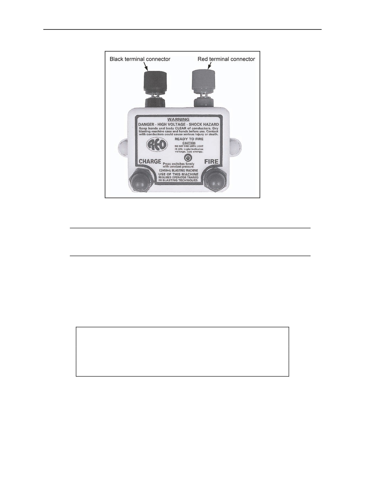
Chapter 1
Figure 1-25. CD450-4J Blasting Machine
General Operating Procedures
Note. In temperatures below 32°F, keep the CD450-4J warm until it is ready to use. During cold
temperatures, fresh batteries should be used with each use. The CD450-4J is not waterproof and
when wet will fail to operate.
1-84. General operating procedures should be conducted on the CD450-4J as follows:
Step 1. Perform the operational test before bringing the blasting machine into the blast area.
Step 2. Obtain the electric detonator (a device containing a sensitive explosive intended to
produce a detonation wave) (JP 1-02) firing recommendations from the detonator manufacturer.
Check the blasting circuit calculations before connecting to the blasting machine.
Step 3. Connect the detonator wires to the lead lines using a series or other circuits that are
recommended by the detonator manufacturer.
Step 4. Ensure that all personnel have moved to a safe location.
CAUTION
Keep the lead lines shunted during wiring of the electric detonators.
Personal injury or damage to equipment may result from long-term
failure to follow correct procedures.
Step 5. Check the electric detonator circuit continuity and resistance (including the lead lines)
using an approved ohmmeter.
Step 6. Shunt the lead lines after checking the circuits until the blast is ready to be initiated.
Step 7. Remove the shunted lead lines connection, and connect the wires to the terminals on the
blasting machine.
1-28
FM 3-34.214
11 July 2007

Military Explosives
DANGER
Keep your hands and body clear of the conductors. Contact with
electrical conductors could cause serious injury or death. Failure
to comply may cause death or permanent injury.
Step 8. Depress the CHARGE switch and hold it down. The READY-TO-FIRE indicator lights
up when the capacitor reaches 450 volts. Releasing the CHARGE switch will discharge the
capacitor within 3 seconds.
Step 9. Continue holding the CHARGE switch down until the READY-TO-FIRE indicator
lights up. Wait at least 2 seconds, and then firmly depress the FIRE switch. Continue holding
both switches down until the firing operation is complete.
Note. If the blasting machine should fail to fire, release both switches, disconnect and shunt the
lead lines, and notify personnel of the blast delay.
Step 10. Wait 3 seconds after the firing operation is complete, and then release both switches.
Step 11. Disconnect and shunt the lead lines.
Step 12. Secure the blasting machine.
FIRING WIRE AND REEL
1-85. The paragraphs below discuss the firing wire and reel. Discussed are the lengths and types of firing
wire and the use of the firing wire reel.
FIRING WIRE
1-86. Wire for firing electric charges is available in 200- and 500-foot coils. The two-conductor American
wire gauge (AWG) number 18 is a plastic- or rubber-covered wire available in 500-foot rolls. This wire is
wound on an RL39A reel unit. The single-conductor, AWG number 20 annunciator wire is available in
200-foot coils and is used to make connections between blasting caps and firing wire. The WD1/telegraphic
transfer (TT) communication wire will also work, but it requires a greater power source if more than 500
feet is used. Blasting machines will not initiate the full-rated number of caps connected with more than 500
feet of WD1/TT wire. As a rule of thumb, 10 less caps than the rating of the machine should be used for
each additional 1,000 feet of WD1/TT wire employed.
FIRING WIRE REEL
1-87. The RL39A reel, with spool, accommodates 500 feet of wire. The reel has a handle assembly, a
crank, an axle, and two carrying straps (Figure 1-26, page 1-30). The fixed end of the wire extends from the
spool through a hole in the side of the drum and fastens to two brass thumb-out terminals. The carrying
handles are two U-shaped steel rods. A loop at each end encircles a bearing assembly to accommodate the
axle. The crank is riveted to one end of the axle, and a cotter pin holds the axle in place on the opposite
end.
11 July 2007
FM 3-34.214
1-29
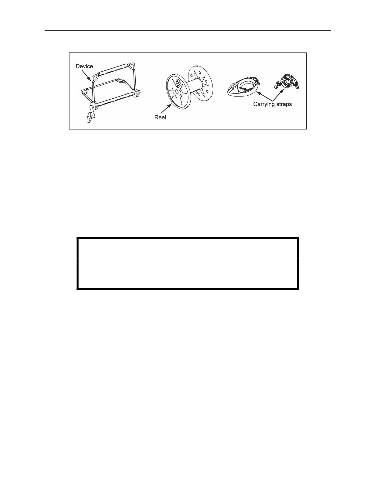
Chapter 1
Figure 1-26. RL39A Firing Wire Reel
NONELECTRIC FIRING DEVICES
1-88. The paragraphs below discuss nonelectric firing devices. Discussed are the uses and functions of
M60 and M81 fuse igniters.
M60 FUSE IGNITER
1-89. This device is used for igniting a timed blasting fuse in all weather conditions, even underwater, if
properly waterproofed. The fuse is inserted through a rubber sealing grommet and into a split collet. This
procedure secures the fuse when the end cap on the igniter is tightened (Figure 1-27). With the safety pin
removed, pull the pull ring to release the striker assembly, and allow the firing pin to initiate the primer and
ignite the fuse. Chapter 2 gives detailed operating instructions for the M60 igniter.
WARNING
Never attach an M60 igniter to the M151, M152, or detonating
cord. Failure to comply could result in immediate personal injury
or damage to equipment.
1-30
FM 3-34.214
11 July 2007
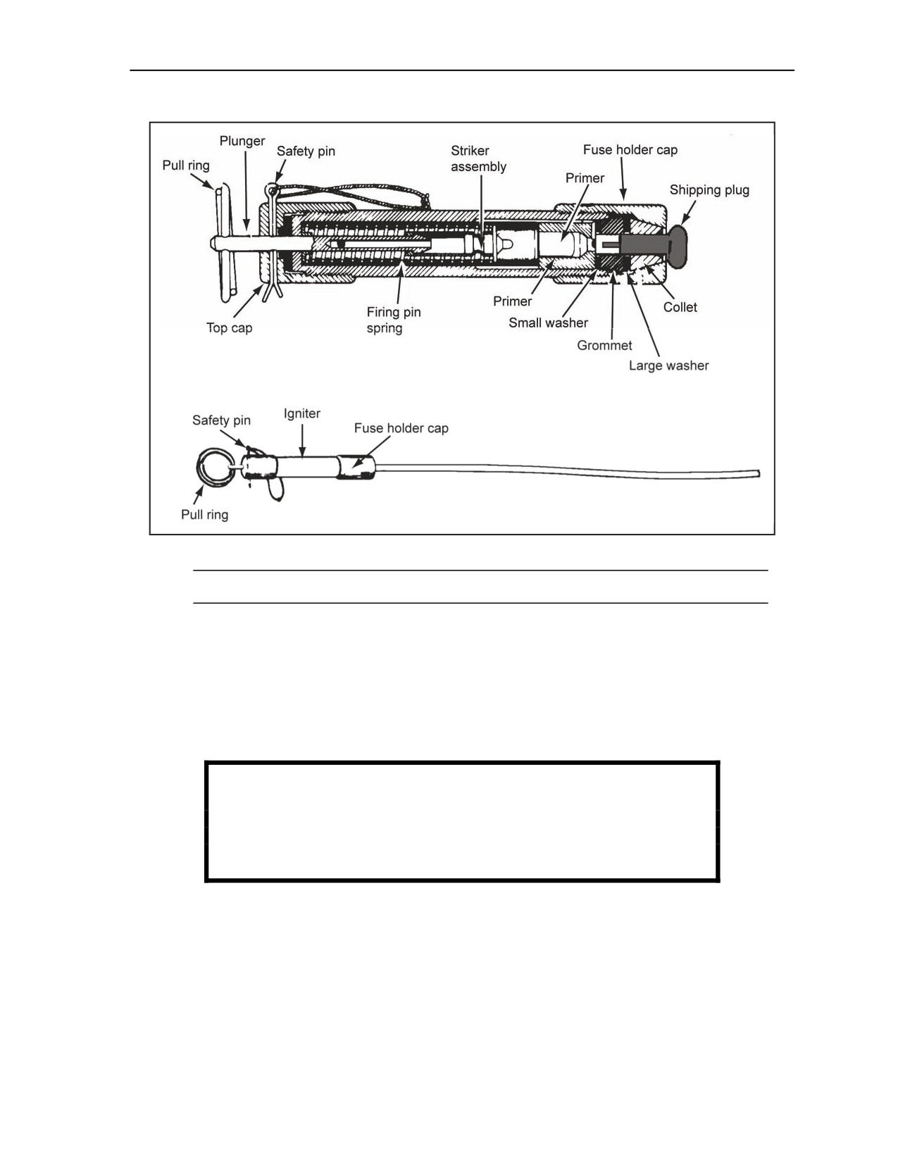
Military Explosives
Figure 1-27. M60 Fuse Igniter
Note. The M60 fuse igniter will neither physically secure the shock tube nor reliably initiate it.
M81 FUSE IGNITER
1-90. The design and function of the M81 fuse igniter is similar to the M60 fuse igniter. The M81 has a
more energetic primer and has two protective plugs in the fuse holder cap (Figure 1-28, page 1-32). A hard-
plastic shipping plug keeps foreign material out of the primer and it should be removed before inserting the
shock tube into the igniter. The shock tube reducer helps secure the shock tube into the M81 igniter. Both
plugs should be removed before using the M81 with the M700 time fuse, M14, or M18 MDI components.
See Chapter 2 for the use of the M81 with MDI components.
WARNING
Never attach an M81 igniter to the M151, M152, or detonating
cord. Failure to comply could result in immediate personal injury
or damage to equipment.
11 July 2007
FM 3-34.214
1-31
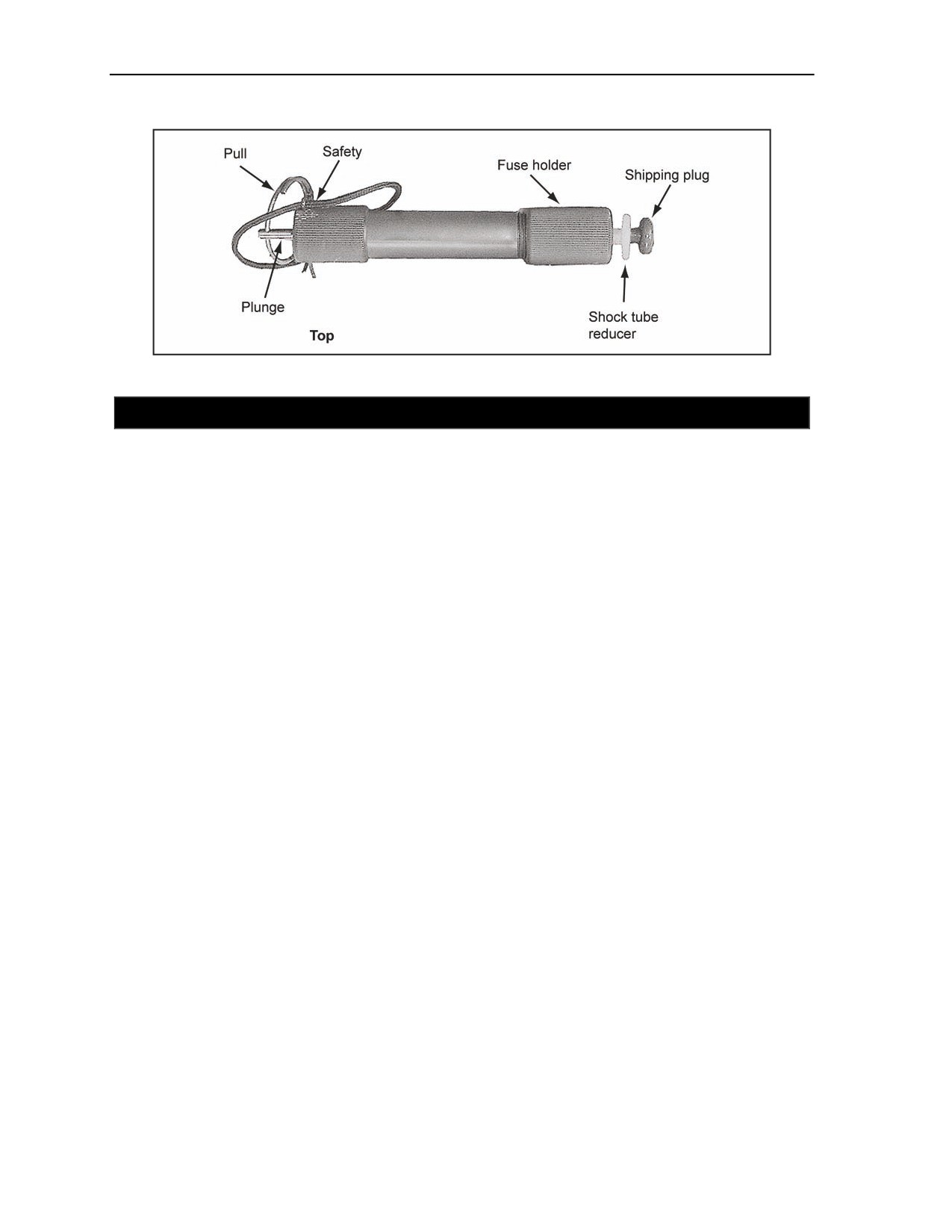
Chapter 1
Figure 1-28. M81 Fuse Igniter
SECTION IV - EXPLOSIVES IDENTIFICATION
PURPOSE
1-91. Tables 1-5 through 1-7, pages 1-33 through 1-41, provide a quick reference for demolition materials
common to combat engineering. This is not a comprehensive list and is subject to change.
MATERIALS
1-92. Table 1-5 and Table 1-6, page 1-36, list materials by type, item, status, national stock number (NSN),
and Department of Defense identification code (DODIC). To avoid problems when requesting materials,
use current supply publications.
1-93. Table 1-7, pages 1-37 through 1-41, is used to cross-reference demolition materials by DODIC.
Materials are listed by DODIC in ascending order and by nomenclature.
1-32
FM 3-34.214
11 July 2007

Military Explosives
Table 1-5. Demolition Materials
Type
Item
Status
NSN
DODIC
Electric blasting
M6, special
Live
1375-00-028-5224
M130
caps
Electric cap
Inert
1375-00-621-8370
M098
J1
Live
1375-00-028-5226
M131
Nonelectric
M7
Live
1375-01-057-6439
M131
blasting caps
Nonelectric cap
Inert
1375-00-621-8362
M097
M1, flash-vented
Live
1377-00-219-8567
M842
M1A1, flash-vented
Live
1377-00-691-1075
M851
Electric squibs
M1, commercial
Live
1377-00-028-5205
M851
Squib, closed end
Live
1377-00-837-3337
M900
Detonator
M1, concussion
Live
1375-00-028-5173
M540
M1, pull
Live
Replaced by M142
ML03
M1A1, pressure
Live
Replaced by M142
ML03
M3, tension
Live
Replaced by M142
ML03
Firing devices,
M5, pressure-release
Live
1375-00-028-5190
M627
coupling bases,
and bodies
M142, multipurpose
Live
1375-01-040-1526
ML03
M122, device
Live
1375-01-021-0606
ML02
M1, delay
Live
1375-00-028-5175
M616
Coupling base
Live
1375-00-699-5236
M327
Destructor
M10, universal
Live
1375-00-028-5171
M241
M11
Live
1375-01-415-1232
ML47
M11, practice
Inert
1375-01-412-0160
MN36
M16
Live
1375-01-449-9601
MN39
M12
Live
1375-01-415-1230
MN02
M12, practice
Inert
1375-01-412-8813
MN35
M13
Live
1375-01-415-1231
MN03
M14
Live
1375-01-415-1233
MN06
Nonelectric
M14, practice
Inert
1375-01-411-6346
MN37
blasting caps
M15
Live
1375-01-415-1234
MN07
M15, practice
Inert
1375-01-411-6345
MN38
M18
Live
1375-01-449-9602
MN41
M19
Live
1375-01-494-6939
MN86
M20, practice
Inert
1375-01-494-6929
MN87
M21
Live
1375-01-494-6945
MN88
M22, practice
Inert
1375-01-494-6934
MN89
M23
Live
1375-01-494-6941
MN90
Boosters
M151
Live
1375-01-467-8646
MN68
M152
Live
1375-01-467-8685
MN69
11 July 2007
FM 3-34.214
1-33

Chapter 1
Table 1-5. Demolition Materials
Type
Item
Status
NSN
DODIC
M152, practice
Inert
1375-01-470-2399
MN75
Blasting cap and
M9
Live
1375-01-415-1229
ML45
shock tube holder
Igniter
M81
Live
1375-01-415-1235
MN08
1/4 lb
Live
1375-00-926-9394
M030
TNT
1/2 lb
Live
1375-00-028-5140
M031
1 lb
Live
1375-00-028-5142
M032
M5A1
Live
1375-00-028-5148
M038
Composition C4
M112
Live
1375-00-724-7040
M023
Sheet explosives
M186
Live
1375-00-728-4108
M060
Dynamite
M1
Live
1375-00-724-9613
M591
Cratering charge
40 lb
Live
1375-00-028-5145
M039
M2A4, 15 lb
Live
1375-00-028-5237
M420
Shaped charges
M3, 40 lb
Live
1375-00-088-6691
M421
40 lb
Live
1375-00-630-3074
M992
Demolition
M183
Live
1375-00-926-3985
M757
assemblies
M37
Live
1375-00-028-5245
M756
Bangalore
M1A2
Live
1375-00-926-1948
M028
torpedos
M1A3
Live
1375-01-528-7226
MP03
M157
Live
1375-00-729-4632
M444
M173
Live
1375-00-812-3972
M443
Projected charges
M58A2/4/5
Live
1375-01-133-4189
M913
demolition kits
M68A2
Inert
1375-01-125-6521
M914
MICLIC, rocket
Live
1340-01-118-2838
J143
M117, flash
Live
1370-00-028-5256
L598
Booby trap
M118, illuminating
Live
1370-00-028-5257
L599
simulators
M119, whistling
Live
1370-00-028-5255
L600
Hand grenade
Live
1370-00-752-8124
L601
M18, green
Live
1330-00-289-6851
G940
M18, yellow
Live
1370-00-289-6854
G945
Smoke grenades
M18, red
Live
1330-00-289-6852
G950
M18, violet
Live
1330-00-289-6853
G955
Demolition
M4, fuel thickener
Live
1365-00-926-4076
K917
accessories
M700, time fuse
Live
1375-00-028-5149
M670
Time fuse
Inert
1375-00-628-9033
M671
M60, fuse igniter
Live
1375-00-691-1671
M766
Detonating cord
Live
1375-00-965-0800
M456
1-34
FM 3-34.214
11 July 2007

Military Explosives
Table 1-5. Demolition Materials
Type
Item
Status
NSN
DODIC
Detonating cord
Inert
1375-00-621-8373
M458
Priming adapter
NA
1375-00-565-4141
M002
M8, cap holder
NA
1375-00-926-4105
M166
M2, crimpers
NA
5120-00-029-0683
NA
Galvanometer
NA
6625-00-539-8444
NA
BA245/U battery
Live
6135-00-128-1632
NA
BA2245/U battery
Live
6135-00-833-9909
NA
M51, test set
NA
6625-00-999-3454
NA
Blasting machine, 10 cap
Live
1375-00-782-5541
NA
Blasting machine, 10 cap
Live
1375-00-935-9173
NA
Blasting machine, M34
Live
1375-00-567-0223
NA
DR8, reel
NA
8130-00-407-7859
NA
RL39A, reel cable
NA
3895-00-498-8343
NA
18 AWG, firing wire
NA
6145-00-299-6172
NA
Electric wire
NA
6145-00-542-3968
NA
Electric wire
NA
6145-00-284-0394
NA
Detonating cord clip
NA
1375-00-212-4602
NA
11 July 2007
FM 3-34.214
1-35

Chapter 1
Table 1-6. U.S. Mines
Type
Item
Status
NSN
DODIC
M14
Live
1345-00-028-5108
K121
M17T34, practice
Live
1345-00-348-2576
K122
M16
Live
1345-00-173-2714
K092
M16A1
Live
1345-00-529-7303
K092
AP
M16A2
Live
1345-00-965-0742
K092
M16
Inert
1345-00-799-7391
K150
M26
Live
1345-00-678-9822
K146
M18A1
Live
1345-00-710-6946
K143
M1, chemical
Live
1345-00-289-6938
K260
M15
Live
1345-00-028-5118
K180
M12
Practice
1345-00-028-5117
K230
M20
Practice
1345-00-344-2368
K231
AT
M21
Live
1345-00-729-4263
K181
M69
Practice
1345-00-182-3148
K233
M23, chemical
Live
1345-00-542-1580
K257
M128, dispenser
NA
1095-00-397-3456
NA
M75, AT mine
Live
1345-01-078-4104
K184
GEMSS
M74, AP mine
Live
1345-01-076-3497
K151
M79
Practice
1345-01-074-9370
K234
1-36
FM 3-34.214
11 July 2007

Military Explosives
Table 1-7. DODIC Index for Demolition Materials
DODIC
Nomenclature
DODIC
Nomenclature
K001
Activator, AT mine, M1
K090
Mine, AP, M2
K002
Activator, AT mine, practice, M1
K091
Mine, AP, inert, M2
K003
Activator, AT mine, M2
K092
Mine, AP, M16
K004
Trip wire assembly, F/M16A2
K105
Mine, AP, practice, M8
K005
Intervalometer, 38/A
K120
Mine, AP, M3
K008
Firing device, AP mine, M57
K121
Mine, AP, M14
K009
Firing device, AP mine, XM123
K122
Mine, AP, practice, M17T34
K010
Burster, incendiary, M4
K139
Mine, AP, practice, M68
K013
Spool, AP mine
K140
Mine, AP, empty, M3
Dispense and mine, aircraft, practice,
K015
K141
Mine, AP, M18
M132
Dispense and mine, aircraft, training,
K016
K143
Mine, AP, M18
M133
K018
Can, crew-trained, M133
K144
Mine, AP, inert, M18
K020
Dispense and mine, aircraft, M56
K145
Mine, AP, M18A1
K021
Intervalometer, system, F/M47
K146
Mine, AP, M26
K027
Chg, mine ejection
K150
Mine, AP, inert, M16
K028
Chg, mine ejection
K151
GEMSS, AP, M74
K030
Primer igniter, AP mine, fuse, M10A1
K170
Mine, AT, M7
K031
Primer igniter, AP mine, fuse, M10A2
K250
Mine, AT, M19
K040
Chg, spotting, AP mine, M8
K917
Thickener, fuel
K041
Chg, spotting, AP mine, M8A1
M001
Adapter, priming, plastic, M1A3 (round)
K050
Fuse, AT mine, M603
M002
Adapter, priming, plastic, M1A4 (hex)
K051
Fuse, AT mine, M604
M020
Chg, shaped, RDX, 0.062 lb
K054
Fuse, AP mine, combination, M7A1
M022
Chg, shaped, PETN, 827 lb
K055
Fuse, AP mine, combination, M10A1
M023
Chg, block, composition C4, 1.25 lb
K056
Fuse, AP mine, combination, M10A2
M024
Chg, block, PETN or RDX, 2 lb
Chg, composition C4, HE, M58 or
K058
Fuse, AP mine, combination, M605
M025
M58A1, 2,000 lb
K060
Fuse, AT mine, M619
M026
Kit, demolition, bangalore torpedo, M1A1
K061
Fuse, AT mine, XM608
M027
Chg, block, practice, MK37-0
K062
Fuse, mine FMU-30/B
M028
Kit, demolition, lin, PETN, 0.75 lb
K063
Fuse, mine, inert, FMU-30/B
M029
Chg, flex, lin, PETN, 0.75 lb
K064
Fuse, AT mine, M616
M030
Chg, block, TNT, 0.25 lb
K065
Fuse, AT mine, M606
M031
Chg, block, TNT, 0.5 lb
K066
Fuse, AT mine, dispense, M56
M032
Chg, block, TNT, 1 lb
K067
Fuse, F/M 21
M034
Chg, block, TNT, 8 lb
11 July 2007
FM 3-34.214
1-37

Chapter 1
Table 1-7. DODIC Index for Demolition Materials
DODIC
Nomenclature
DODIC
Nomenclature
M035
Chg, chain, TNT, 20 lb
M107
Cap, SP electric, 3.7-sec delay
M036
Chg, chain, TNT, 2.5 lb
M108
Cap, SP electric, 4.5-sec delay
M037
Chg, block, C2, 2.25 lb
M109
Cap, SP electric, instantaneous
M038
Chg, block, composition C4, 2.25 lb
M110
Cap, electric, high-strength
Cap, electric, nonsubmersible, practice,
M039
Chg, block, cratering, 40 lb
M112
M10
M040
Chg, block, TNT, 55 lb
M118
Cap, SP electric, 6.4-sec delay
M041
Chg, block, C2, 0.5 lb
M120
Cap, electric, No. 8
M043
Chg, block, TNT, 49 lb
M125
Cap, electric, No. 8, 2d delay
M044
Chg, block or shaped, HDX 1, 12 lb
M126
Cap, electric, No. 8, 3d delay
Chg, flex, lin, composition A, MK8-3,
M046
M127
Cap, electric, No. 8, 4th delay
50 lb
M048
Chg, block, C2, 2.5 lb
M128
Cap, SP electric, 7.6-sec delay
Chg, lin, practice, M68 or M68A1,
M051
M129
Cap, electric, SP strength
2,000 lb
M060
Chg, roll, PETN, M186, 25 lb
M130
Cap, SP electric, submersible, J2/M6
M065
Chg, block, H6, 4 lb
M131
Cap, nonelectric, nonsubmersible, M7
M078
Cap, electric, nonsubmersible, M4
M138
Cap, electric, nonsubmersible
M080
Chg, flex, lin, practice, PETN, 0.007 lb
M153
Cap, electric, nonsubmersible
M081
Chg, flex, lin, PETN, 14 oz
M236
Destructor, explosive, PETN
M082
Chg, flex, lin, PETN, 22 oz
M240
Destructor, explosive, PETN
M083
Chg, flex, lin, PETN, 28 oz
M241
Destructor, explosive, universal, M10
M084
Chg, flex, lin, PETN, 36 oz
M327
Base, coupling, with primer
M085
Chg, flex, lin, PETN, 43 oz
M328
Base, coupling, without primer
M086
Chg, flex, lin, PETN, 50 oz
M405
Chg, propelling, earth rod, M112
M087
Chg, flex, lin, PETN, 57 oz
M418
Chg, shaped, RDX, MK47-0, 1.5 lb
Chg, shaped, composition B,
M091
Cap, SP electric,10-sec delay
M420
M2A4/M2A3E1, 15 lb
M092
Cap, SP electric, 11.2-sec delay
M421
Chg, shaped, composition B, M3A2, 40 lb
M093
Cap, SP electric, 12.5-sec delay
M431
Chg, rigid, lin, Amatol, 35 lb
M094
Cap, SP electric, 14-sec delay
M442
Kit, demolition, practice, M174
M095
Cap, SP electric, 15.6-sec delay
M443
Kit, demolition, projected chg, M173
M097
Cap, nonelectric, practice
M444
Kit, demolition, projected chg, M157
M098
Cap, electric, inert
M446
Kit, demolition, projected chg, M1
M101
Cap, SP electric, 0.8-sec delay
M455
Cord, detonating, Primacord®, PETN
M102
Cap, SP electric, 1.4-sec delay
M456
Cord, detonating, reinforced, waterproof
M103
Cap, SP electric, 2.2-sec delay
M457
Cord, detonating, PETN
M104
Cap, SP electric, 2.9-sec delay
M458
Cord, detonating, inert
1-38
FM 3-34.214
11 July 2007

Military Explosives
Table 1-7. DODIC Index for Demolition Materials
DODIC
Nomenclature
DODIC
Nomenclature
M466
Detonating, percussion, MK2
M627
Device, firing, steel
M482
Chg, steel
M630
Device, firing, pull-type, M1
M483
Chg, controlled, steel
M631
Device, firing, pressure-release, M1
M485
Cutter, HE, 1-in jaw
M632
Device, firing, zinc
M486
Cutter, HE, 2-in jaw
M635
Device, firing, pull-type, M1
M540
Kit, detonator, percussion, M1
M637
Device, firing, zinc
M559
Kit, demolition, M175
M639
Device, firing, pressure-release, M5
M587
Dynamite, nitroglycerin
M641
Device, firing, tension-release
M591
Dynamite, military, M1
M643
Device, firing, tension-release
M598
Destroyer, crypto equip, M1A2
M644
Device, firing, aluminum
Destroyer, crypto equip, incendiary,
M600
M650
Device, firing, aluminum
M2A1
Destroyer, crypto equip, incendiary,
M601
M670
Fuse, timed, M700
M1A2, TH1
Destroyer, document, emergency,
M605
M671
Fuze, timed, inert
incendiary, M1A2, TH4
M606
Destroyer, crypto equip, M1A2, TH4
M680
Cylinder, ignition, flame thrower, M1
M607
Destroyer, crypto equip, M2A1
M745
Kit, conversion, depth chg
M608
Destroyer, crypto equip, TH4
M756
Assembly, chg, M37, 20 lb
M609
Destroyer, crypto equip, M2A1, TH4
M757
Assembly, chg, composition C4, M183
M610
Destroyer, file, incendiary, ABC-M4
M767
Igniter, fuse, timed, practice, XM77
Chg, shaped, practice, inert, MK37-1,
M611
Destroyer, file, incendiary, ABC-M4
M784
7 lb
Assembly, composition C2 or C3,
M612
Destroyer, incendiary, TH3
M790
MK127-0, 20 lb
M615
Igniter, document destroyer, M25
M791
Assembly, tetrytol, MK133-0, 20 lb
Assembly, block, composition C4,
M616
Device, firing, M1, 6- to 14-min delay
M792
MK138-0, 20 lb
M617
Set, device, firing, M1
M810
Primer, percussion, improved, No. 3
M619
Device, firing, M1, 12- to 32-min delay
M814
Destroyer, document, 55 gal, M4
M620
Device, firing, M1, 45- to 115-min delay
M820
Kit, explosive, earth rod, No. 1
M622
Device, firing, M1, 210- to 570-min delay
M821
Kit, explosive, foxhole digger
Device, firing, M1, 610- to 1,130-min
Chg, shaped, composition H6, MK741,
M623
M832
delay
1.5 lb
Chg, shaped, practice, inert, MK74-0,
M624
Device, firing, brass
M833
1.3 lb
M625
Device, firing, zinc
M836
Cap, electric, dry, instantaneous
M626
Device, firing, zinc
M855
Cap, electric, dry, 0.5-sec delay
M910
Igniter, primer and base, XM110
ML10
Chg, shaped, flex, lin, 30 gr/ft
11 July 2007
FM 3-34.214
1-39

Chapter 1
Table 1-7. DODIC Index for Demolition Materials
DODIC
Nomenclature
DODIC
Nomenclature
Chg, flex, lin, composition C4, M58A1,
M913
ML11
Chg, shaped, flex, lin, 40 gr/ft
2,000 lb
M914
Chg, lin, practice, M68A1, 2,000 lb
ML12
Chg, shaped, flex, lin, 60 gr/ft
Chg, shaped, practice, inert, MK47-0,
M916
ML13
Chg, shaped, flex, lin, 75 gr/ft
1.5 lb
M936
Chg, block, inert, 0.25 lb
ML14
Chg, shaped, flex, lin, 125 gr/ft
Chg, shaped, composition H6, MK470,
M957
ML15
Chg, shaped, flex, lin, 225 gr/ft
1.13 lb
M974
Cap, electric, submersible
ML16
Chg, shaped, flex, lin, 300 gr/ft
M975
Fuze, crypto equip, M210, 0.7-sec delay
ML17
Chg, shaped, flex, lin, 400 gr/ft
M976
Chg, block, composition H6, 4 lb
ML18
Chg, shaped, flex, lin, 500 gr/ft
M977
Cord, detonating, PETN
ML19
Chg, shaped, flex, lin, 600 gr/ft
M980
Chg, roll, PETN, 20 lb
ML23
Cap, bridge wire, X175E
M981
Chg, roll, PETN, 20 lb
ML25
Chg, flex, lin, M59
M982
Chg, roll, PETN, 20 lb
ML26
Chg, lin, practice, M69
M983
Chg, roll, PETN, 20 lb
ML27
Detonator, percussion, MK53
M984
Chg, roll, PETN, 20 lb, M766
ML32
Primer, percussion, M27
M986
Chg, roll, PETN, 20 lb
ML36
Kit, fuse, inert, M1147
M987
Chg, block, composition C4, 2 lb
ML37
Kit, fuse, live, M1133
M988
Chg, block, composition C4, 0.5 lb
ML45
Blasting cap and shock tube holder, M9
M989
Initiator, explosive
ML47
Cap, nonelectric, M11
M990
Detonator, flash
ML78
Chg, shaped, practice, MK47-0
M992
Chg, shaped, practice, inert, M3, 40 lb
ML82
Kit, fuse, live, M1134
M993
Chg, roll, PETN, 20 lb
MN02
Cap, blasting, nonelectric, M12
M994
Chg, roll, PETN, 20 lb
MN03
Cap, blasting, nonelectric, M13
Chg, lin, composition H6, MK86-0,
M995
MN06
Cap, blasting, nonelectric, M14
0.002 kg
Chg, lin, composition H6, MK87-0,
M996
MN07
Cap, blasting, nonelectric, M15
0.013 kg
M997
Chg, lin, composition H6, MK88-0, 1 kg
MN08
Igniter, M81
Chg, rigid, lin, composition C3, MK89-0,
M998
MN39
Cap, nonelectric, M16
4 kg
ML03
Device, firing, plastic, M142
MN41
Cap, blasting, nonelectric, M18
ML04
Cutter, HE
MN68
Booster, demolition chg, M151
ML05
Cutter, HE
MN69
Booster, demolition chg, M152
ML07
Cap, electric, nonsubmersible
MN75
Booster, demolition chg, inert, M152
ML08
Kit demolition, XM268
MN86
Cap, nonelectric, dual mini, M19
ML09
Chg, shaped, flex, lin, 20 gr/ft
MN87
Cap, nonelectric, dual mini, inert, M20
MN88
Cap, nonelectric, mini, M21
MW84
Kit, demo, tubular SWS, MK75-0
1-40
FM 3-34.214
11 July 2007

Military Explosives
Table 1-7. DODIC Index for Demolition Materials
DODIC
Nomenclature
DODIC
Nomenclature
MN89
Cap, nonelectric, mini, inert, M22
MW85
Kit, accessory, demolition, MK29-0
MN90
Cap, nonelectric, mini, M23
MW86
Kit, firing device, MK48-0
MW02
Valve, explosive, electrically initiated
MW87
Kit, firing device, training, MK122-0
MW26
Cell, arming, MK1-8, 80-min delay
MX14
Kit, centering, cavity chg
MW27
Clip, detonating cord, M1
MY01
Clip, detonating cord, M1
MW28
Connector, plastic
MZ21
Cap, nonelectric, inert, 500 ft
MW29
Element, delay, MK19/0
MZ22
Cap, nonelectric, inert, 30 ft
Kit, demo, bangalore torpedo, M1 or
MW30
MZ23
Cap, delay, nonelectric, inert
M1A1
MW31
Holder, detonator, MK2-0
MZ24
Cap, delay, nonelectric, inert, 70 ft
MW37
Driver, power-actuated, MK22-0
SS89
Chg, shock test, R/U725
MW38
Float, rigid, polyurethane
XW60
Kit, firing device, MK138-0
MW49
Connector, detonating cord, plastic
XW65
Chg, shock tube, R/U1260
MW52
Chg, sheet, MK57-0
XW66
Chg, shock test, R/U1259
MW53
Chg, sheet, MK56-0
XW67
Chg, shock test
MW56
Device, safety and arming, MK39-0
YW05
Kit, chg, training, MK75-0
11 July 2007
FM 3-34.214
1-41

This page is intentionally left blank.
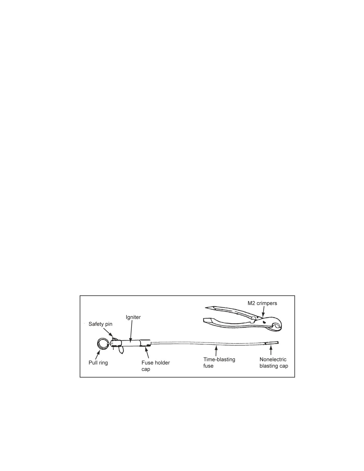
Chapter 2
Initiating Sets, Priming Methods, Firing Systems, and
Modernized Demolition Initiators
Explained in this chapter are the different types of initiating sets and how to prepare
them. Also discussed are the different methods for priming each explosive type and
how to set up demolition firing systems.
SECTION I - INITIATING SETS
CAUTION
See the safety procedures in Chapter
6 before undertaking any
demolition mission. Personal injury or damage to equipment may result
from long-term failure to follow correct procedures.
NONELECTRIC INITIATING SETS
2-1. A nonelectric system uses a nonelectric blasting cap as the initiator. The paragraphs below describe a
nonelectric system.
COMPONENTS ASSEMBLY
2-2. The initiating set consists of a fuse igniter (that produces the flame that lights the time-blasting fuse), a
time-blasting fuse (that transmits the flame that fires the blasting cap), and a nonelectric blasting cap (that
provides adequate shock to detonate the explosive) (Figure 2-1). For MDI components and the preparation
sequence, see Section IV of this chapter. When combined with detonating cord, a single-initiating set can
fire multiple charges.
Figure 2-1. Nonelectric Initiating Set
PREPARATION SEQUENCE
2-3. Preparing demolitions for nonelectric initiation follows specified processes. These processes are
discussed below.
11 July 2007
FM 3-34.214
2-1
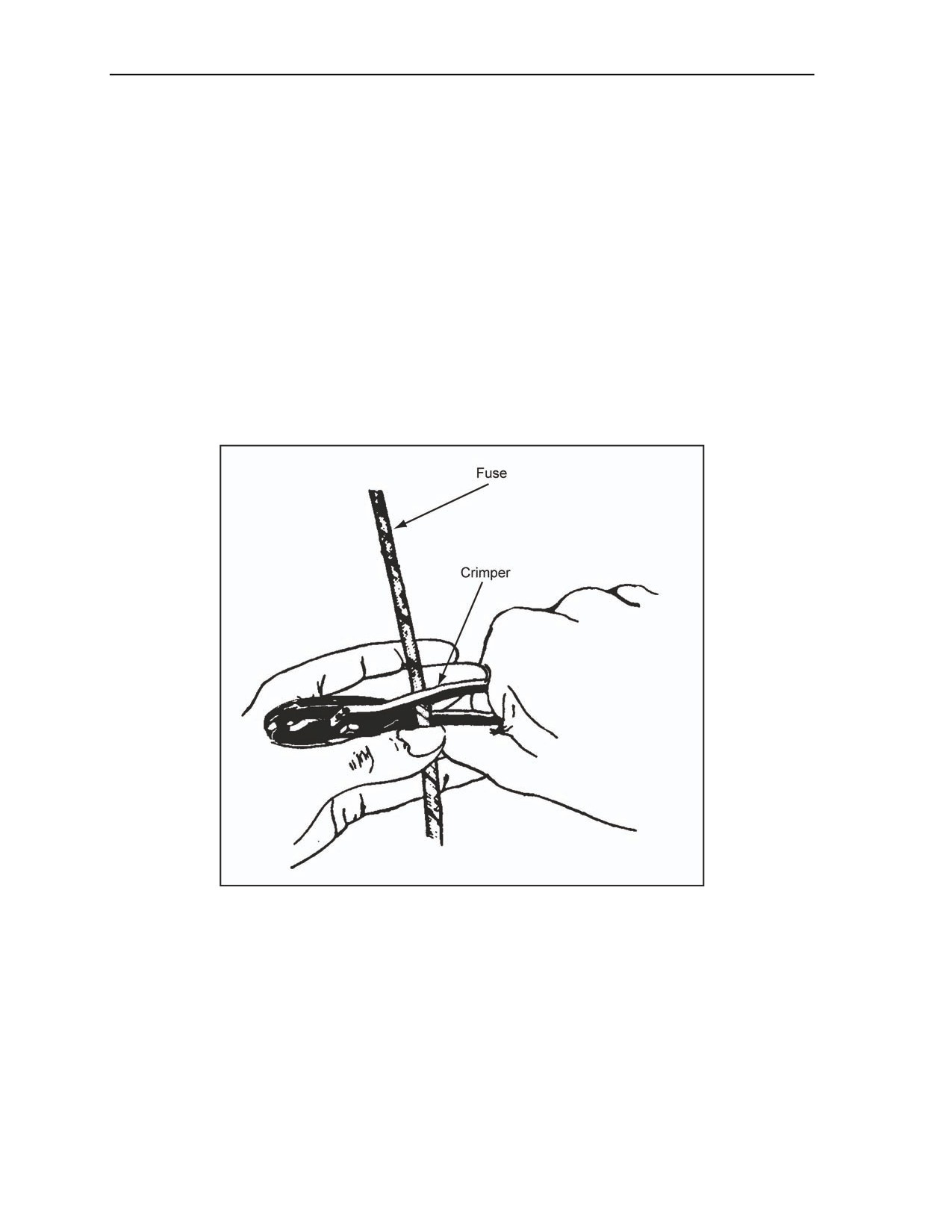
Chapter 2
Check the Time Fuse
2-4. Every coil of fuse, or remnant of a coil, is tested using the burning rate test before use. One test per
day per coil is enough. The first and last 6 inches of a coil is never used because moisture may have
penetrated the coil to this length. An M2 crimper is used to cut and discard a 6-inch length from the
working end of the fuse (Figure 2-2). A 3-foot length of fuse is cut to check the burning rate. The fuse is
ignited and the time it takes for the fuse to burn is noted. The burning rate per foot is computed by dividing
the burn time (in seconds) by the length (in feet). Another test is performed to verify the results if the test
burn does not fall within 5 seconds of a 40-second-per-foot burn rate. The coil is placed in the foil packet
and marked with its corresponding burn rate once the burn rate is calculated.
DANGER
Test-burn a 3-foot length of time-blasting fuse to determine the
exact burn rate before use. Failure to comply may cause death or
permanent injury.
Figure 2-2. Cutting a Time Fuse
2-2
FM 3-34.214
11 July 2007

Initiating Sets, Priming Methods, Firing Systems, and Modernized Demolition Initiators
Prepare the Time Fuse
2-5. The fuse is cut long enough to allow the person detonating the charge to reach safety (walking at a
normal pace) before the explosion. This distance is walked and timed before cutting the fuse to length. The
formula for determining the length of time fuse required is—
Time required (min) x 60 (sec/min)
= Fuse length (ft)
Burning rate (sec/ft)
Make the Cut Squarely Across the Fuse
2-6. The fuse should not be cut too far in advance since the fuse may absorb moisture into the open ends.
The time fuse should not be allowed to bend sharply because the black powder core may crack, resulting in
a misfire.
Attach the Fuse Igniter
2-7. Attach an M60 or M81 weatherproof fuse igniter by unscrewing the fuse holder cap two or three
turns, but do not remove the cap. The shipping plug is pressed into the igniter to release the split collar
(Figure 1-27, page 1-29). The plug and plastic shock tube holder is rotated and removed from the igniter.
The free end of the time fuse is inserted as far as possible into the space left by the removed shipping plug.
The holder cap is tightened to hold the fuse and weatherproofs the joint .
Install the Priming Adapter
2-8. The time fuse is placed through the adapter before installing (crimping) the blasting cap onto the fuse
when using a priming adapter to hold a nonelectric blasting cap. The adapter threads should be pointed to
the end of the time fuse that will receive the blasting cap.
Prepare the Blasting Cap
2-9. The blasting cap should be prepared by—
Inspecting. Hold the cap between your thumb and ring finger of one hand with the forefinger of
the same hand on the closed end of the blasting cap. Inspect the blasting cap by looking into the
open end (a yellow-colored ignition charge should be seen). Do the following if dirt or any
foreign matter is present:
Aim the open end of the cap at the palm of your second hand.
Gently bump the wrist of your hand holding the cap against the wrist of the other hand.
Do not use the cap if the foreign matter does not dislodge.
Placing and crimping. Use the following procedures to attach a nonelectric blasting cap to the
time fuse or the detonating cord:
Hold the time-blasting fuse vertically with the square-cut end up. Slip the blasting cap
gently down over the fuse so the flash charge in the cap touches the fuse.
11 July 2007
FM 3-34.214
2-3
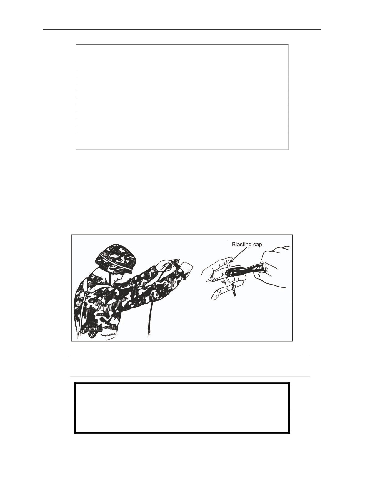
Chapter 2
CAUTION
If the charge in the cap is not in contact with the fuse, the fuse may not
ignite the cap (misfire). Never force a time fuse into a blasting cap (for
example, by twisting). If the fuse end is flat or too large to enter the
blasting cap freely, roll the fuse between your thumb and fingers until it
will freely enter the cap. A rough, jagged-cut fuse inserted in a blasting
cap can cause a misfire. If the cutting jaws of the M2 crimper are
unserviceable, use a sharp, nonsparking knife to cut the fuse. When
using a knife to cut the fuse squarely, cut the fuse against a solid,
nonsparking surface such as wood. Personal injury or damage to
equipment may result from long-term failure to follow correct
procedures.
Grasp the fuse with your thumb and ring finger while applying slight pressure with your
forefinger on the closed end of the cap.
Use the opposite hand to grasp the crimpers. Place the crimping jaws around the cap at a
point 1/8 to 1/4 inch from the open end. Ensure that your thumb and ring finger that hold
the fuse is below the crimpers. Rest the second finger of your hand holding the fuse on top
of the crimpers to prevent the crimpers from sliding up the cap (Figure 2-3, page 2-4).
Extend both arms straight out while rotating the hands so that the closed end of the blasting
cap is pointing away from your body and away from other personnel.
Tilt your head downward and crimp the blasting cap by firmly squeezing the M2 crimper
handles together. Inspect the crimp when finished.
Figure 2-3. Crimping a Blasting Cap Onto a Fuse
Note. Attach the M60 or M81 fuse igniter to the time fuse before crimping a blasting cap to the
opposite end. Do not remove the safety pin until the charge is ready to be detonated.
WARNING
To avoid cap detonation, crimp blasting caps 1/8 to 1/4 inch from
the open end of the cap. Failure to comply could result in
immediate personal injury or damage to equipment.
2-4
FM 3-34.214
11 July 2007
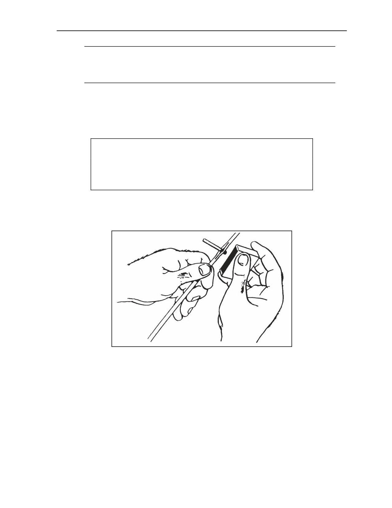
Initiating Sets, Priming Methods, Firing Systems, and Modernized Demolition Initiators
Note. Protect the joint between the cap and the time-blasting fuse with a coat of sealing
compound or a similar substance if the blasting cap is to remain in place several days before
firing. This sealing compound does not make a waterproof seal; therefore, fire submerged
charges immediately. See Chapter 6, Section II, for procedures on handling nonelectric misfires.
FUSE INITIATION
2-10. To fire the assembly, hold the M60 or M81 igniter in one hand and then remove the safety pin with
the other. While grasping the pull ring, give it a quick, hard pull. In the event of a misfire, reset the M60 or
M81 by pushing the plunger all the way in (for the M60 only, rotate it left or right 180°), and attempt to fire
as before.
CAUTION
Never initiate a fuse igniter underwater. Personal injury or damage to
equipment may result from long-term failure to follow the correct
procedures.
2-11. If a fuse igniter is not available, light the time-blasting fuse with a match. The fuse is split at the end
(Figure 2-4) and the head of an unlit match is placed in the powder train. The inserted match head is lighted
with a flaming match or rubbed against the abrasive on the matchbox. It may be necessary to use two match
heads during windy conditions.
Figure 2-4. Lighting a Time Fuse With a Match
COMPONENTS ASSEMBLY
2-12. An electric system uses an electric blasting cap as the explosion initiator. The initiating set consists
of an electric blasting cap, the firing wire, and a blasting machine (Figure 2-5, page 2-6). An electric
impulse (usually provided by a blasting machine) travels through the firing wire and blasting cap leads,
detonating the blasting cap, which initiates the explosion. Radio waves can also detonate electric blasting
caps. Therefore, observe the minimum safe distances listed in the tables in Chapter 6 at all times. A single-
initiating set can be used to initiate the detonating cord or multiple charges. TM 9-1375-213-34&P provides
detailed information about electric blasting equipment.
11 July 2007
FM 3-34.214
2-5
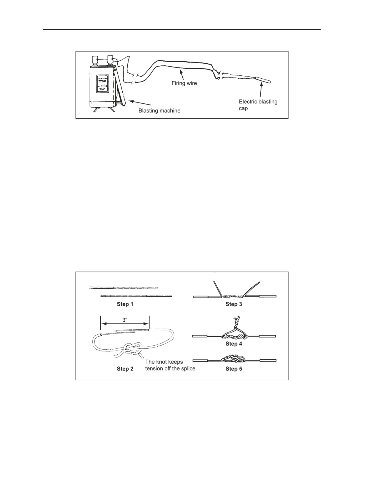
Chapter 2
Figure 2-5. Electric Initiating Set
CIRCUIT INITIATION
2-13. At this point, the initiating set is complete. The blasting machine should not be connected until all
personnel are accounted for and clearance is received to fire the demolition. When all personnel are clear,
“fire in the hole” is called three times, then the blasting machine is installed and demolition is initiated.
Chapter 6 covers the procedures for electric misfires.
ELECTRIC WIRE SPLICING
2-14. The paragraphs below discuss electric wire splicing. Explained is the preparation, method, and
precautions for electric wire splicing.
Preparation
2-15. Before splicing, strip the insulating material from the end of the insulated wires. About 1 1/2 inches
of insulation should be removed from the end of each wire (Figure 2-6, step 1). Any coating on the wire
should be removed (such as enamel) by carefully scraping the wire with the back of a knife blade or other
suitable tool. The bare wire should not be nicked, cut, or weakened. After scraping, lightly twist multiple-
strand wires.
Figure 2-6. Western Union Pigtail Splice and Tension Knot
Method
2-16. Use the Western union pigtail splice (Figure 2-6) to splice two wires. The two pairs of wires are
spliced in the same way as the 2-wire splice (Figure 2-7). When splicing, use the following steps:
Step 1. Protect the splices from tension damage by tying the ends in an overhand or square knot
(tension knot), allowing enough length for each splice (Figure 2-6, step 2).
2-6
FM 3-34.214
11 July 2007
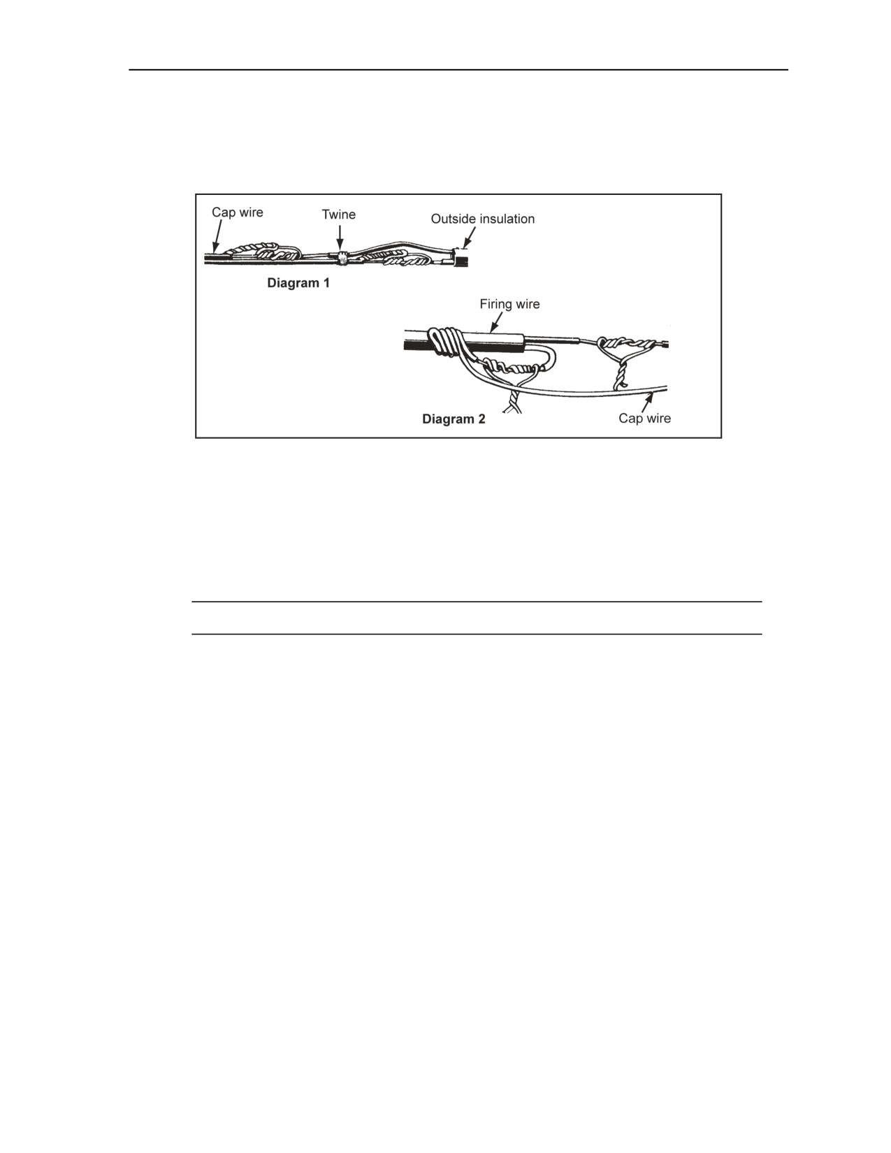
Initiating Sets, Priming Methods, Firing Systems, and Modernized Demolition Initiators
Step 2. Make three twists with each wire (Figure 2-6, step 3).
Step 3. Twist the ends together with an additional three turns (Figure 2-6, step 4).
Step 4. Flatten the splice, but not so far that the wire crimps itself and breaks (Figure 2-6,
step 5).
Figure 2-7. Two-Wire Splice
Precautions
2-17. A short circuit may occur at a splice if caution is not used. For example, when splicing pairs of wires,
stagger the splices and place a tie between them (Figure 2-7, Diagram 1). Another method of preventing a
short circuit in a splice is using the alternate method (Figure 2-7, Diagram 2). In the alternate method, the
splices are separated rather than stagger them. Splices are insulated from the ground or other conductors by
wrapping them with friction tape or electric insulating tape.
Note. Always insulate the splices.
SERIES CIRCUITS
2-18. The two types of series circuits include the common series circuit and the leapfrog series circuit
(Figure 2-8, page 2-8). A common series circuit is used to connect two or more electric blasting caps to a
single-firing wire. The leapfrog series method of connecting caps in a series is useful for firing any long
line of charges.
11 July 2007
FM 3-34.214
2-7
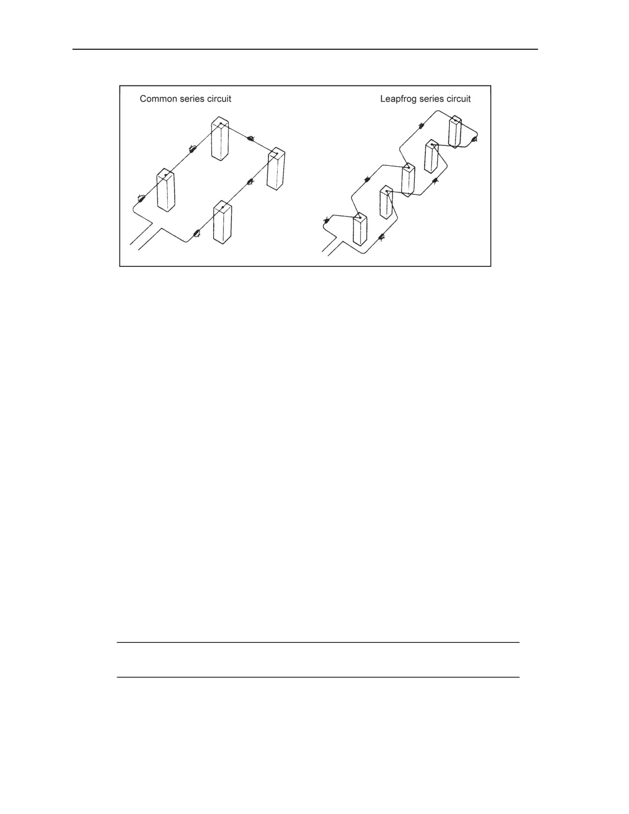
Chapter 2
Figure 2-8. Series Circuit
Common Series Circuit
2-19. The series circuit is prepared by connecting one blasting cap to another until only two lead wires are
free. Shunt the two lead wires until you are ready to proceed with the next step. The free ends of the cap
lead wires are connected to the ends of the firing wire. Connecting wires (usually an annunciator wire) are
used when the distance between the blasting caps is greater than the length of the usual cap lead wires.
Leapfrog Series Circuit
2-20. The leapfrog series method is performed by starting at one end of a row of charges and priming
alternate charges to the opposite end, and then priming the remaining charges on the return leg of the series.
This method eliminates the necessity for a long-return lead from the far end of the line of charges. See
Appendix E for additional information on series circuits. This circuit type is rarely needed since detonating
cord, when combined with a single blasting cap, will fire multiple charges.
ELECTRIC INITIATING SETS
2-21. See Appendix E for the power requirements for series firing circuits. The following steps are used to
make an electric initiating set:
Step 1. Test and maintain control of the blasting machine.
Test the blasting machine to ensure that it is operating properly (Chapter 1).
Control access to all blasting machines (responsibility of the supervisor).
Step 2. Test the M51 test set.
Check the M51 test set to ensure that it is operating properly (Chapter 1).
Perform both the open- and short-circuit tests.
Step 3. Test the firing wire on the reel (shunted and unshunted) (Figure 2-9).
Separate the firing wire leads at both ends, and connect the leads at one end to the posts of
the M51 test set. Squeeze the test set handle.
Note. The indicator lamp should not flash. If it does, the flash of the lamp indicates a short
circuit in the firing wire.
Shunt the wires at one end, and connect the leads from the other end to the posts of the M51
test set. Squeeze the test set handle.
2-8
FM 3-34.214
11 July 2007
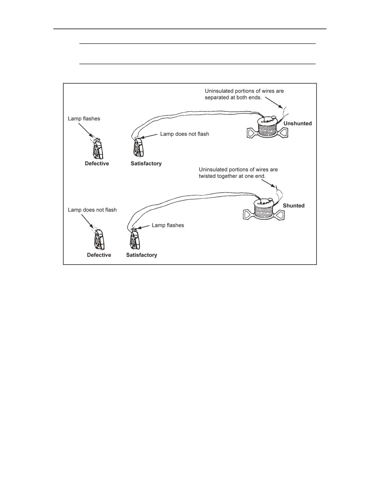
Initiating Sets, Priming Methods, Firing Systems, and Modernized Demolition Initiators
Note. The indicator lamp should flash. If it does not, the failure of the lamp to light indicates a
break in the firing wire. At least three 180° twists should be used to shunt the wires.
Shunt both ends of the firing wire after testing.
Figure 2-9. Testing a Firing Wire on a Reel
Step 4. Lay out the firing wire.
Lay out the firing wire from the charges to the firing point after locating a firing point.
Ensure that this firing point is located a safe distance away from the charges (Chapter 6).
Bury the firing wire or lay it flat on the ground. Do not allow vehicles to drive over the
firing wire or personnel to walk on the firing wire.
Keep the firing wire as short as possible. Avoid creating any loops in the wire (lay it in as
straight a line as possible). Cut the firing wire to length, and ensure that it is shunted.
Step 5. Retest the firing wire (shunted and unshunted).
Perform the open- and close-circuit tests again. Ensure that the process of unreeling the
wire did not separate broken wires not found when the wire was tested on the reel.
Guard the firing position continually from this point on. Ensure that no one tampers with
the wires or fires the charges prematurely.
Use hand signals to indicate the test results.
11 July 2007
FM 3-34.214
2-9

Chapter 2
Note. Hand signals are necessary because of the distance involved between the charges and the
firing position. The Soldier testing the wire can give these signals directly to the Soldier at the
opposite end of the wire or, if they cannot see each other, through intermediate positions or over
the radio. The tester indicates to the assistant that he wants the far end of the firing wire
unshunted by extending both arms straight out at shoulder height. After unshunting the firing
wire, the assistant at the far end of the wire repeats the signal, indicating to the tester that his end
is unshunted. When the tester wants the far end of the firing wire shunted, he signals to the
assistant by clasping his hands together and extending his arms over his head, elbows bent,
forming a diamond shape. After shunting the firing wire, the assistant repeats the signal,
indicating to the tester that the wire is shunted.
Shunt both ends of the firing wire after completing the tests.
Step 6. Test the electric blasting caps.
Remove the cap from its spool. Place the cap in the palm of your hand with the lead wires
passing between your index and middle fingers.
Wrap the wire around the palm of your hand twice to prevent tension on the wires in the
cap and the cap from being dropped.
Grasp the wire spool with your free hand, and unreel the wire letting the wire pass between
your fingers while turning the spool. Unreel the cap wires completely from the cardboard
spool. Avoid allowing the wires to slip off the ends of the cardboard spool, since this will
cause excessive twists and kinks in the wires and prevent the wires from separating
properly.
Place the blasting cap under a sandbag or helmet while extending the wires to their full
length.
Test the blasting caps away from all other personnel. Keep your back to the blasting cap
when testing it.
Remove the short-circuit shunt from the lead wires.
Hold or attach one lead wire to one of the binding posts of the M51. Hold or attach the
second lead wire to the other binding post.
Squeeze the test set handle.
Note. The blasting cap is good if the indicator lamp flashes. If the lamp does not flash, the cap is
defective; do not use it.
Ensure that the cap wires are kept shunted when not testing them.
Step 7. Connect the series circuit (if used) using one of the series circuits shown in Figure 2-8,
page 2-8. Use the following procedures:
Test all blasting caps (step 6) separately, before connecting them in a circuit.
Join blasting-cap wires together using the Western union pigtail splice and tension knot
(Figure 2-6, page 2-6). Protect all joints in the circuit with electrical insulation tape. Do not
use the cardboard spool that comes with the blasting cap to insulate these connections.
Test the entire electrical cap circuit. Connect the two free blasting cap wires to the M51 test
set after the series is completed.
Note. The indicator lamp should flash to indicate a good circuit. If the lamp does not flash, check
the connections and blasting caps again.
Test the cap circuit, and then shunt the two free blasting cap wires until you are ready to
connect them to the firing wire.
Step 8. Connect the firing wire to the cap wire.
Connect the free leads of the blasting caps to the firing wire before priming the charges or
taping a blasting cap to a detonating cord ring main.
2-10
FM 3-34.214
11 July 2007

Initiating Sets, Priming Methods, Firing Systems, and Modernized Demolition Initiators
Use a Western union pigtail splice to connect the firing wire to the blasting cap wires.
Insulate the connections with tape. Never use the cardboard spool that comes with the
blasting cap to insulate this connection.
Note. The firing wire is likely to break when bent to fit into the spool.
Step 9. Test the entire firing circuit. Test the circuit from the firing point before priming the
charges with electric caps or connecting the blasting caps to the firing circuit. Use the following
procedures:
Ensure that the blasting caps are under protective sandbags while performing this test.
Connect the ends of the firing wire to the M51 test set.
Squeeze the test handle. The indicator lamp should flash, indicating a proper circuit.
Shunt the ends of the firing wire.
WARNING
Do not prime the charges with electric blasting caps or connect
electric blasting caps to the detonating cord until all other steps
of the preparation sequence are complete. Failure to comply
could result in immediate personal injury or damage to
equipment.
Step 10. Prime the charges. Prime the charges and return to the firing point. Perform this as the
last step before returning to the firing point and firing the circuit.
WARNING
Prime the charges with the minimum number of personnel on-
site. Failure to comply could result in immediate personal injury
or damage to equipment.
SECTION II - PRIMING SYSTEMS
PRIMING CHARGES
2-22. The four methods of priming charges are MDI, nonelectric, electric, and detonating cord. MDI,
nonelectric, and electric priming involves directly inserting blasting caps into the charges and MDI M151
and MDI M152 boosters into the charges. MDI M151, MDI M152, or detonating cord priming are the
preferred methods for priming all charges since it involves fewer blasting caps, makes priming and misfire
investigation safer, and allows charges to be primed at state of readiness—state 1 (safe) when in place on a
reserved demolition target (a target of known military interest identified for possible future demolition)
(JP 1-02) or mission.
Note. When priming with MDI, refer to Section IV of this chapter.
PRIMING TRINITROTOLUENE DEMOLITION BLOCKS
2-23. Nonelectric blasting caps, electric blasting caps, and detonating cord are used to prime TNT
demolition blocks. Each of these is discussed in the paragraphs below.
11 July 2007
FM 3-34.214
2-11

Chapter 2
NONELECTRIC BLASTING CAP
2-24. TNT blocks have threaded cap wells. If available, use priming adapters to secure nonelectric blasting
caps and timed blasting fuses to TNT blocks with threaded cap wells (Figure 2-10). When priming adapters
are not available, prime TNT blocks with threaded cap wells using the following steps:
Step 1. Wrap a string tightly around the block of TNT. Tie it securely, leaving about 6 inches of
loose string on each end (Figure 2-11).
Step 2. Insert a blasting cap with the fuse attached into the cap well.
Step 3. Tie the loose ends of the string around the fuse to prevent the blasting cap from being
separated from the block. Adhesive tape can also effectively secure blasting caps in charges
(Figure 2-11).
Figure 2-10. Nonelectric Priming With an Adapter
Figure 2-11. Nonelectric Priming Without an Adaptor
ELECTRIC BLASTING CAP
2-25. Electric blasting caps can be used with priming adapters or without priming adapters. The use of
these adapters is discussed in the paragraphs below.
With a Priming Adapter
2-26. The following steps is used for priming a TNT block when using the priming adapter:
Step 1. Prepare the electric initiating set before priming.
2-12
FM 3-34.214
11 July 2007
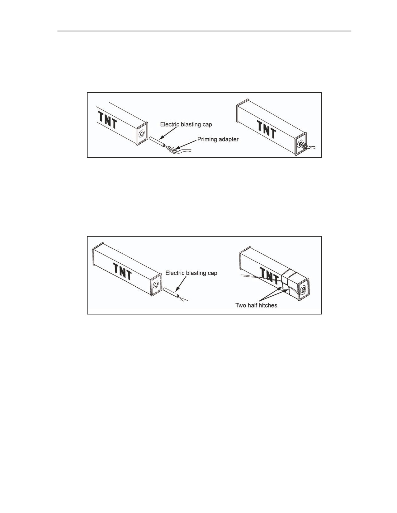
Initiating Sets, Priming Methods, Firing Systems, and Modernized Demolition Initiators
Step 2. Pass the lead wires through the slot of the adapter, and pull the cap into place in the
adapter (Figure 2-12). Ensure that the blasting cap protrudes from the threaded end of the
adapter.
Step 3. Insert the blasting cap into the threaded cap well of the TNT block, and screw the
adapter into place.
Figure 2-12. Electric Priming With an Adapter
Without a Priming Adapter
2-27. The following steps are used if a priming adapter is not available:
Step 1. Prepare the electric initiating set before priming.
Step 2. Insert the electric blasting cap into the cap well. Tie the lead wires around the block,
using two half hitches (Figure 2-13). Allow some slack in the wires between the blasting cap and
the tie to prevent any tension on the blasting cap lead wires.
Figure 2-13. Electric Priming Without an Adapter
DETONATING CORD
2-28. The following methods are used to prime TNT blocks with detonating cord (Figure 2-14, page 2-14):
Common method. Lay one end (1-foot length) of detonating cord at an angle across the
explosive. Wrap the running end around the block three turns, laying the wraps over the standing
end. On the fourth wrap, slip the running end under all wraps, parallel to the standing end, and
draw the wraps tight. Ensure that this forms a clove hitch with two extra turns.
Alternate method. Place a loop of detonating cord on the explosive, leaving enough length on
the end to make four turns around the block, and loop with the remaining end of the detonating
cord. Start the first wrap, and ensure that you immediately cross over the standing end of the
loop. Work your way to the closed end of the loop. Pass the free end of the detonating cord
through the loop, and pull it tight to form a knot around the outside of the block.
11 July 2007
FM 3-34.214
2-13
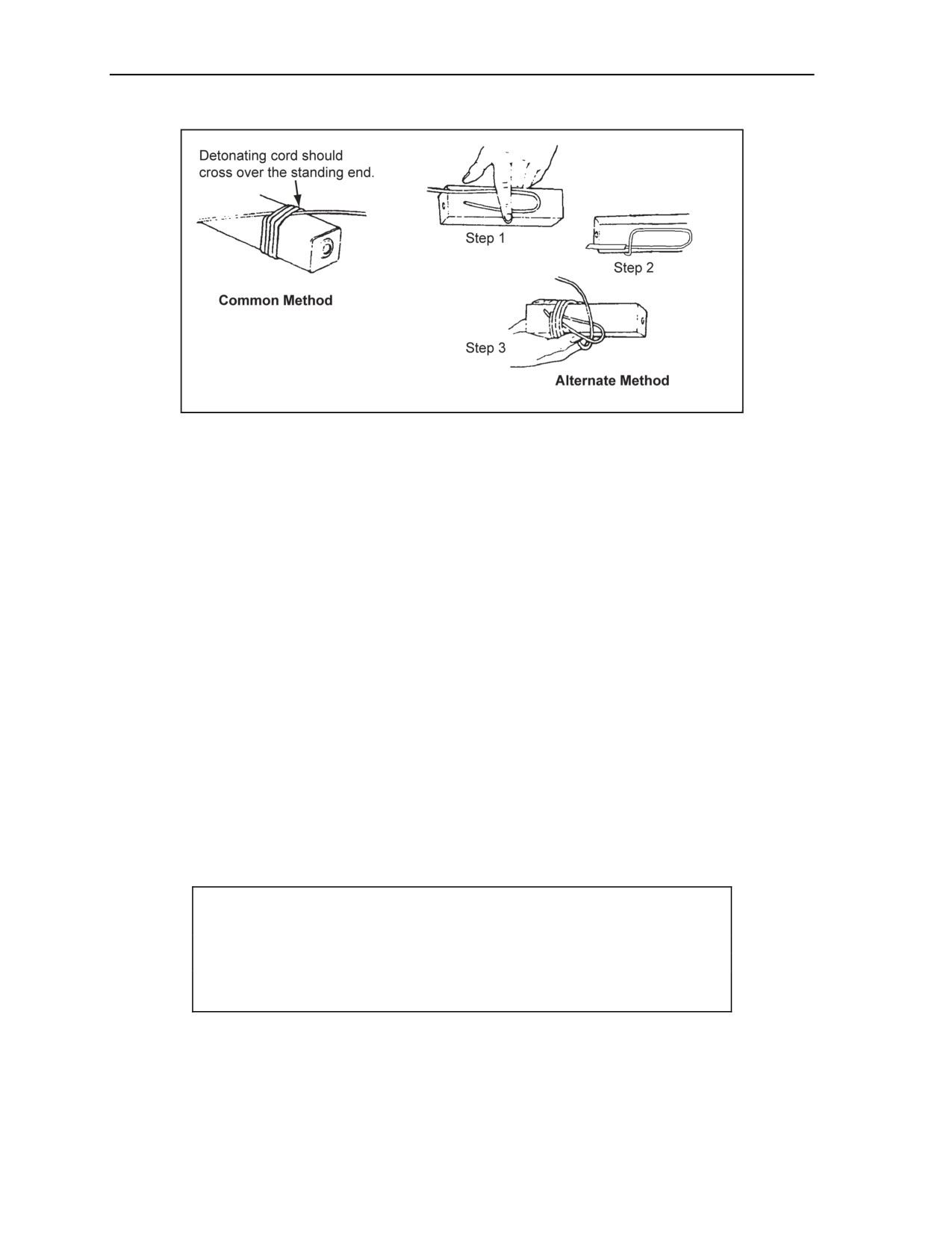
Chapter 2
Figure 2-14. Priming TNT With Detonating Cord
PRIMING M112 (COMPOSITION C4) DEMOLITION BLOCKS
2-29. When priming M112 (composition C4) demolition blocks, nonelectric and electric blasting caps and
detonating cord are used. Each of these is discussed in the paragraphs below.
NONELECTRIC AND ELECTRIC BLASTING CAPS
2-30. Composition C4 blocks do not have a cap well; therefore, one will have to be made. The following
steps are used to make a cap well:
Step 1. Use M2 crimpers or other nonsparking tools to make a hole in the end or on the side of
the block (at the midpoint) large enough to hold the blasting cap.
Step 2. Insert the blasting cap into the hole. Do not force the cap if the blasting cap does not fit
the hole or cut; make the hole larger.
Step 3. Anchor the blasting cap in the block by gently squeezing the plastic explosive around the
blasting cap.
DETONATING CORD
2-31. To prime plastic explosives with detonating cord, use the following steps:
Step 1. Form either an Uli knot, a double overhand knot, or a triple-roll knot as shown in
Figure 2-15.
Step 2. Cut an L-shaped portion of explosive, leaving it connected to the explosive. Ensure that
the space is large enough to insert the formed knot (Figure 2-16).
CAUTION
Use a sharp, nonsparking knife on a nonsparking surface to cut
explosives. Personal injury or damage to equipment may result from
long-term failure to follow correct procedures.
Step 3. Place the knot in the L-shaped cut.
Step 4. Push the explosive from the L-shaped cut over the knot. Ensure that there is at least
1/2 inch of explosive on all sides of the knot.
Step 5. Strengthen the primed area by wrapping it with tape.
2-14
FM 3-34.214
11 July 2007
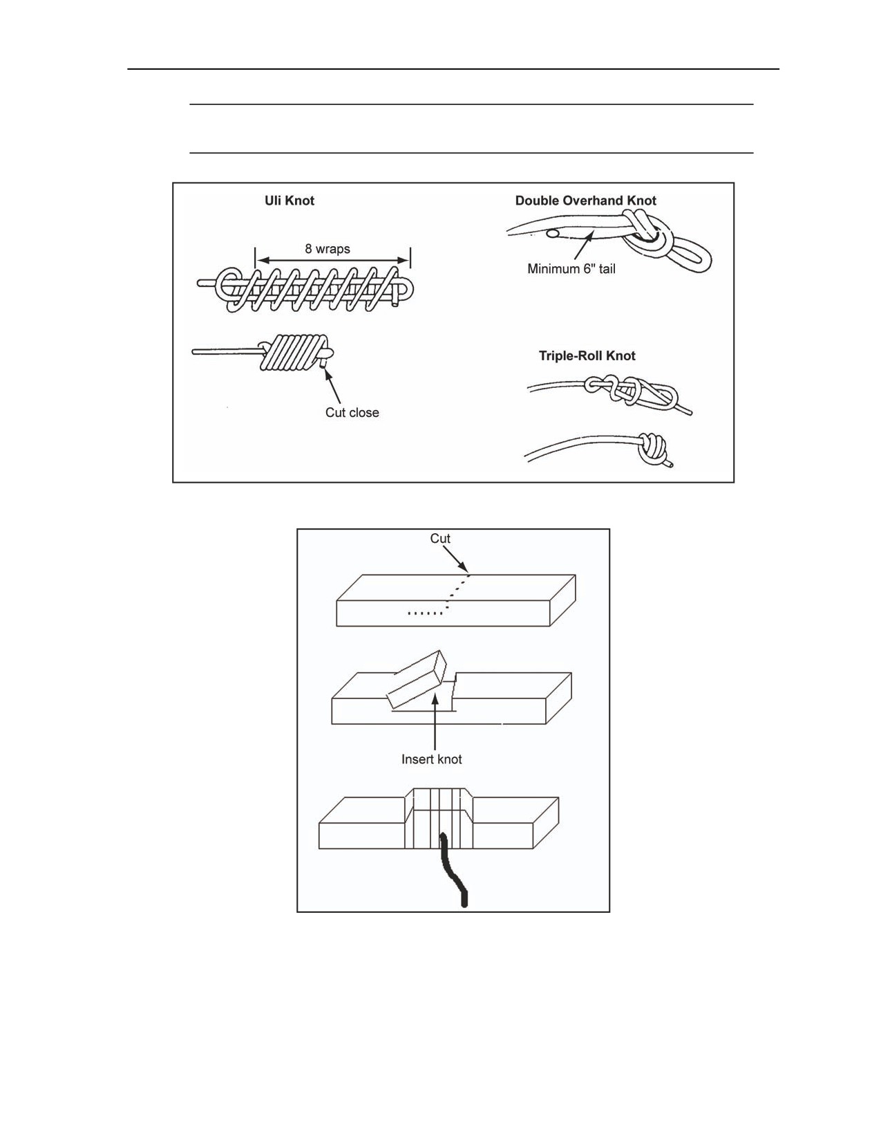
Initiating Sets, Priming Methods, Firing Systems, and Modernized Demolition Initiators
Note. It is not recommended that plastic explosives be primed by wrapping them with detonating
cord, since wraps will not properly detonate the explosive charge.
Figure 2-15. Priming Plastic Explosives With Detonating Cord
Figure 2-16. Priming Composition C4 With an L-Shaped Charge
PRIMING M186 DEMOLITION CHARGES
2-32. M186 demolition charges can be primed by using nonelectric and electric blasting caps or detonating
cord. The use of nonelectric and electric blasting caps and detonating cord is discussed below.
11 July 2007
FM 3-34.214
2-15
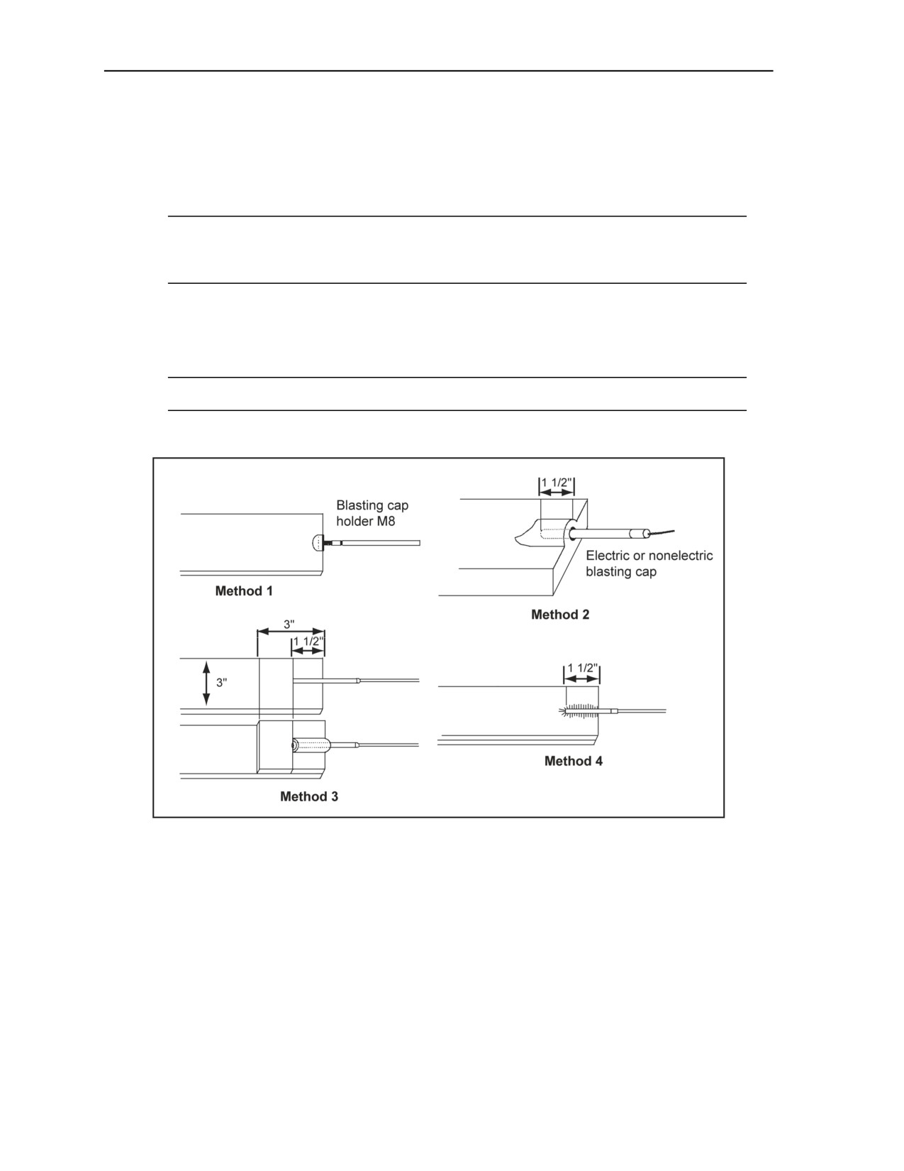
Chapter 2
NONELECTRIC AND ELECTRIC BLASTING CAPS
2-33. One of the following methods can be used to prime M186 demolition charges (Figure 2-17):
Method 1. Attach an M8 blasting cap holder to the end or side of the sheet explosive. Insert an
electric or a nonelectric blasting cap into the holder until the end of the cap presses against the
sheet explosive.
Note. The M8 blasting cap holder has three slanted, protruding teeth, which prevent the clip
from withdrawing from the explosive. Two dimpled spring arms firmly hold the blasting cap in
the M8 holder.
Method 2. Cut a notch in the sheet explosive (about 1 1/2 inches long and 1/4 inch wide). Insert
the blasting cap to the limit of the notch. Secure the blasting cap with a strip of sheet explosive.
Method 3. Place 1 1/2 inches of the blasting cap on top of the sheet explosive, and secure it with
a strip of sheet explosive (at least 3 inches by 3 inches).
Note. When using sheet explosives to cut steel, Method 3 is the preferred method.
Method 4. Insert 1 1/2 inches of the blasting cap between two sheets of explosive.
Figure 2-17. Priming Sheet Explosives
DETONATING CORD
2-34. Sheet explosives can be primed with detonating cord using an Uli knot, double overhand knot, or
triple-roll knot. Insert the knot between two sheets of explosive, or place the knot on top of the sheet
explosive and secure it with a small strip of sheet explosive. The knot must be covered on all sides with at
least 1/2 inch of explosive.
PRIMING DYNAMITE
2-35. Dynamite can be primed at either end or side using either the nonelectric, electric, or detonating cord
priming method. These methods are discussed in the paragraphs below.
2-16
FM 3-34.214
11 July 2007
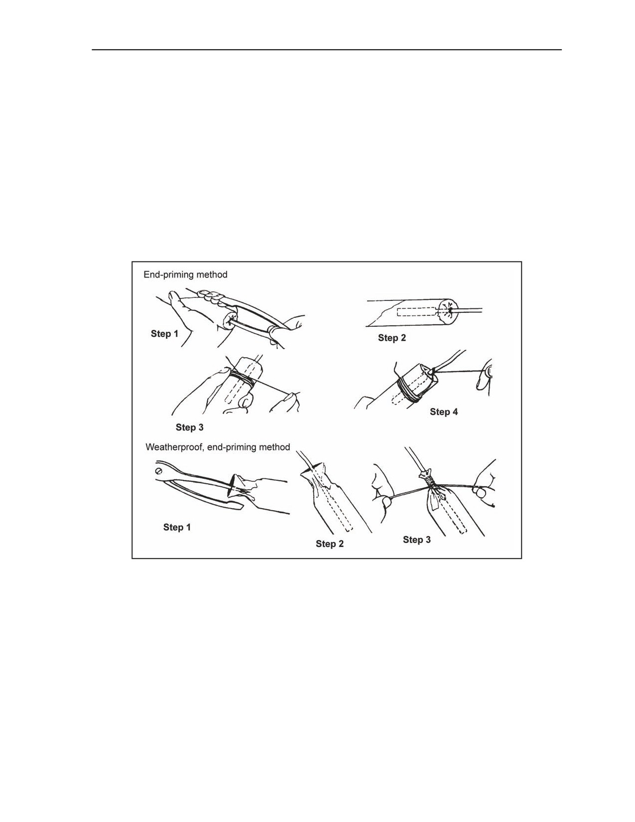
Initiating Sets, Priming Methods, Firing Systems, and Modernized Demolition Initiators
NONELECTRIC AND ELECTRIC PRIMING
2-36. There are three methods for priming dynamite nonelectrically and electrically. They are the—
End-priming method (Figure 2-18). Perform the end-priming as follows:
Step 1. Making a cap well in the end of the dynamite cartridge using M2 crimpers.
Step 2. Inserting a fused blasting cap into the cap well.
Steps 3 and 4. Tying the cap and fuse securely in the cartridge with a string.
Weatherproof, end-priming method (Figure 2-18). Perform the weatherproof, end-priming
method as follows:
Step 1. Unfolding the wrapping at the folded end of the dynamite cartridge and making a
cap well in the exposed dynamite using M2 crimpers.
Step 2. Inserting a fused blasting cap into the cap well.
Step 3. Closing the wrapping around the fuse and fastening the wrapping securely with
string or tape and applying a weatherproof sealing compound to the tie.
Figure 2-18. Nonelectric and Electric End-Priming of Dynamite
Side-priming method (Figure 2-19, page 2-18). Perform the side-priming method as follows:
Step 1. Making a cap well (about 1 1/2 inches long) into the side of the cartridge at one end
using M2 crimpers. Slightly slant the cap well so the blasting cap, when inserted, will be
nearly parallel to the side of the cartridge and the explosive end of the cap will be at a point
nearest the middle of the cartridge.
Step 2. Inserting a fused blasting cap into the cap well.
Step 3. Tying a string securely around the fuse, and then wrapping the string tightly around
the cartridge, making two or three turns before tying it.
Step 4. Weatherproofing the primed cartridge by wrapping a string closely around the
cartridge, extending it an inch or so on each side of the hole to cover it completely and
covering the string with a weatherproof sealing compound.
11 July 2007
FM 3-34.214
2-17
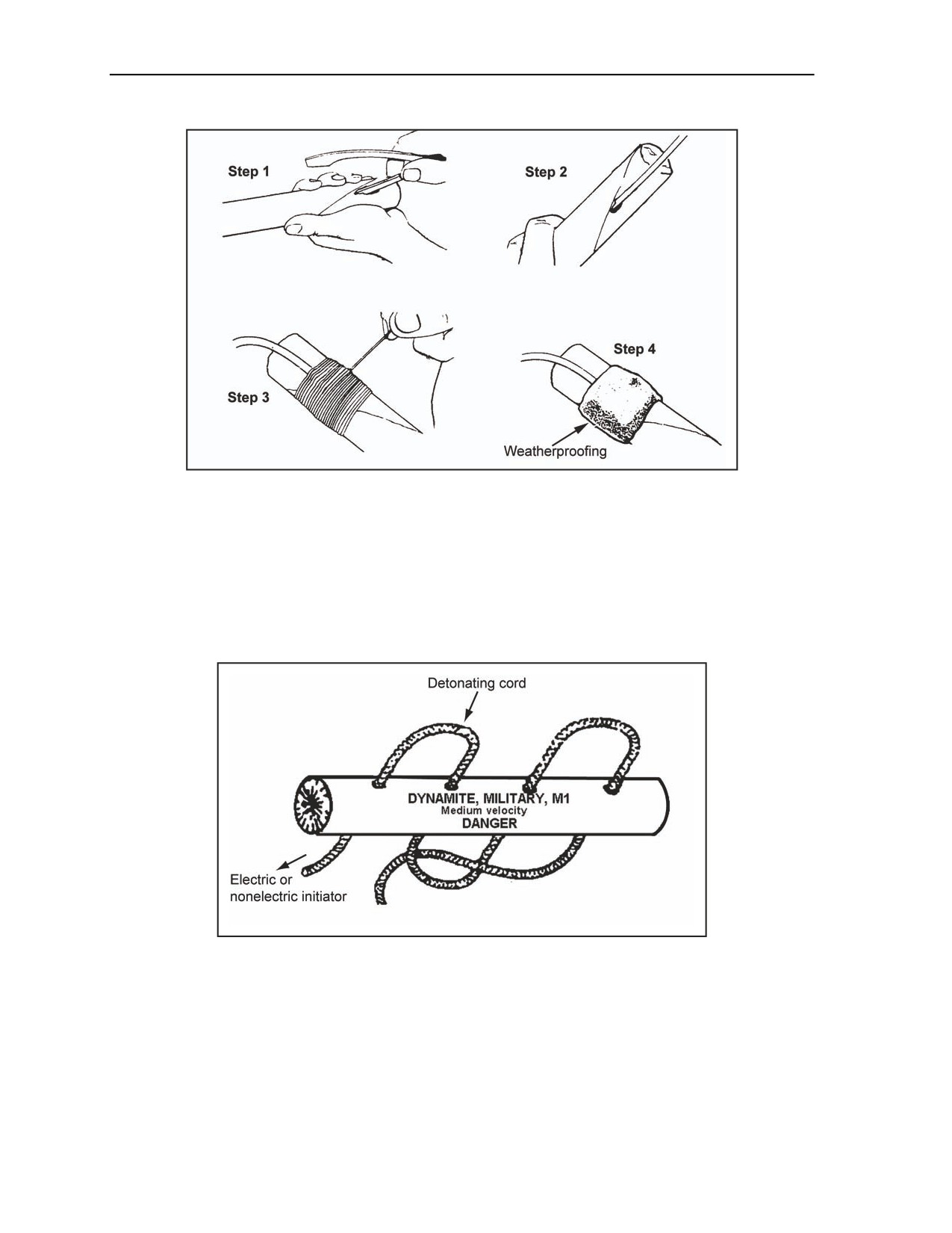
Chapter 2
Figure 2-19. Nonelectric and Electric Side-Priming of Dynamite
DETONATING CORD PRIMING
Detonating cord can be used to prime dynamite. Using the M2 crimpers (about 1 inch from either end of the
dynamite charge), four equally spaced holes should be punched through the dynamite cartridge (Figure 2-20).
The cartridge must be rotated 180˚ after punching each hole to keep the holes parallel. Detonating cord should
be laced through the holes in the same direction that the holes are punched. The dynamite will break if the loops
of the detonating cord are pulled too tightly. To secure the detonating cord tail, pass it between the detonating
cord lace and the dynamite charge.
Figure 2-20. Priming Dynamite With Detonating Cord
PRIMING 40-POUND, COMPOSITION H6 CRATERING CHARGES
2-37. The 40-pound, composition H6 cratering charge is primarily an underground charge; therefore, prime
it only with composition C4 primed with detonating cord. Use dual-priming to protect against misfires as
follows:
Step 1. Prime two packages of composition C4 (Figure 2-21, Diagram 4, page 2-20).
2-18
FM 3-34.214
11 July 2007

Initiating Sets, Priming Methods, Firing Systems, and Modernized Demolition Initiators
Step 2. Dual-prime a single cratering charge by placing the primed composition C4 packages
parallel to the cratering charge and on opposite sides of it and flush with the top. Firmly hold
them in place with duct tape. Instructions and markings on the canister indicate the exact
placement of the composition C4 (Figure 2-21, Diagram 2, page 2-20).
Step 3. Dual-prime two cratering charges by priming them in the same borehole. This requires
one primed composition C4 block on each of the cratering charges, parallel to the charges and
flush with the top. When placed in the borehole, the composition C4 blocks are placed on
opposite sides of the 40-pound charges (Figure 2-21, Diagram 4).
Step 4. Ensure that the detonation-cord branchlines (from the composition C4 block) are long
enough to reach the detonating-cord ring mains after the cratering charge is in the ground. To aid
in clearing possible misfires, place tape on the detonating cord from the cratering charge, 1 foot
up.
2-38. The composition H6 cratering charge replaced the 40-pound ammonium-nitrate cratering charge. If
an ammonium-nitrate cratering charge is drawn from an ammonium supply point (ASP), use the following
steps to prime it:
Step 1. Dual-prime a single cratering charge by placing the detonating cord into the detonating
cord tunnel. Tie an overhand knot with a 6-inch tail at either lower end of the length of the
detonating cord. Use a minimum of 1 pound of explosive when dual-priming a single cratering
charge. Prime the explosives with detonating cord and tape the charge to the center of the
cratering charge (Figure 2-21, Diagram 1).
Step 2. Dual-prime two cratering charges by priming only the detonating cord tunnels of each
charge when placing two charges in the same borehole. The borehole is dual-primed and extra
explosives as shown in Figure 2-21, Diagram 3.
Note. The borehole is dual-primed and extra explosives are not required.
11 July 2007
FM 3-34.214
2-19
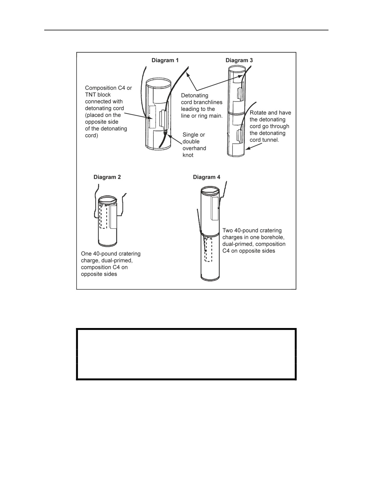
Chapter 2
Figure 2-21. Priming Composition H6 and Ammonium Nitrate Cratering Charges
Step 3. Ensure that the detonating cord branchlines from the 1-pound charge are long enough to
reach the detonating cord ring main after the cratering charge is in the ground. Place tape on the
detonating cord 1 foot up from the cratering charge to aid in clearing possible misfires.
WARNING
Do not prime cratering charges with blasting caps when buried.
Failure to comply could result in immediate personal injury or
damage to equipment.
2-20
FM 3-34.214
11 July 2007

Initiating Sets, Priming Methods, Firing Systems, and Modernized Demolition Initiators
CAUTION
Ammonium nitrate is hygroscopic and ineffective when wet. Therefore,
inspect the metal container for damage or rust. Do not use damaged or
rusty charges. Personal injury or damage to equipment may result from
long-term failure to follow correct procedures.
PRIMING M2A4 AND M3A1 SHAPED CHARGES
2-39. The M2A4 and M3A1 are primed with nonelectric or electric blasting caps. These charges have a
threaded cap well at the top of the cone and are primed with a blasting cap as shown in Figure 2-22, page
2-22. If a priming adapter is not available, use a piece of string, cloth, or tape to hold the cap.
Simultaneously, detonate multiple shaped charges to create a line of boreholes for cratering charges by
connecting each charge into a detonating cord ring or a line main. The detonating cord branchlines must be
of equal length for priming shaped charges when simultaneous detonation is required. The procedures for
priming shaped charges are listed below.
Note. Use the crimp, tie, prime (CTP) method for shaped charges.
WARNING
Do not dual-prime shaped charges. Prime them only with a
blasting cap in the threaded cap well. Failure to comply could
result in immediate personal injury or damage to equipment.
NONELECTRIC SHAPED CHARGE
2-40. Prime nonelectric shaped charges (Figure 2-22, page 2-22) as follows:
Step 1. Place a priming adapter (if using one) on the detonating cord, then crimp a nonelectric
blasting cap to a branchline.
Step 2. Connect the branchline to the ring main.
Step 3. Insert and secure the blasting cap into the threaded cap well of the shaped charge.
Step 4. Make all branchline connections before priming any shaped charges when detonating
multiple shaped charges.
ELECTRIC SHAPED CHARGES
2-41. Electric shaped charges are primed as follows:
Completing the initiating set and firing circuit as described in paragraph 2-21, page 2-8.
Priming the charge.
11 July 2007
FM 3-34.214
2-21
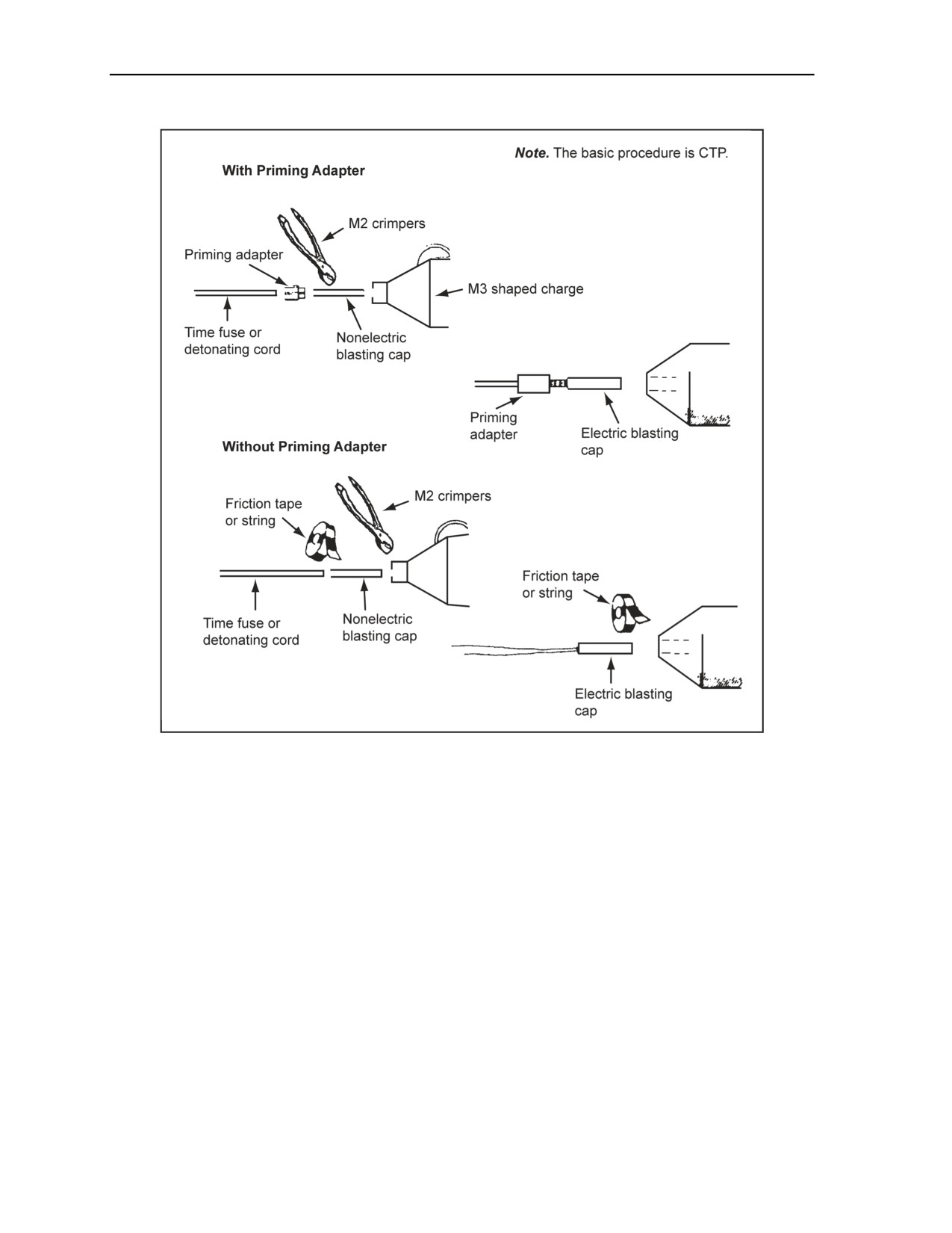
Chapter 2
Figure 2-22. Priming Shaped Charges
PRIMING M1A2 AND M1A3 BANGALORE TORPEDOES
2-42. Nonelectric and electric initiating sets are used when priming the M1A2 and M1A3 bangalore
torpedo. The paragraphs below describe the nonelectric and electric initiating sets, detonating cord, and
dual priming.
NONELECTRIC INITIATING SET
2-43. The blasting cap of a nonelectric initiating set is inserted directly into the cap well of a torpedo
section (Figure 2-23, Diagram 1). If a priming adapter is not available, use tape or string to hold the
blasting cap in place. When priming the bangalore with a nonelectric cap, use the CTP method.
ELECTRIC INITIATING SET
2-44. The blasting cap of an electric initiating set is inserted into the cap well of a torpedo section. If a
priming adapter is not available, hold the cap in place by taping or tying (with two half hitches) the lead
wires to the end of the torpedo. Allow some slack in the wires between the blasting cap and the tie to
prevent tension on the blasting cap leads, and a tension knot is used to join the firing wire to the cap wire
(Figure 2-23, Diagram 2).
2-22
FM 3-34.214
11 July 2007
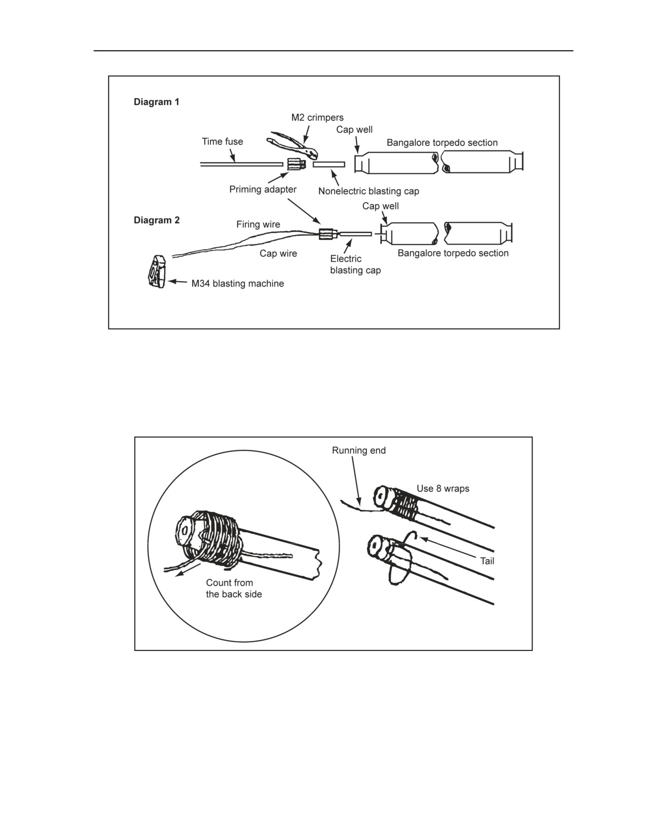
Initiating Sets, Priming Methods, Firing Systems, and Modernized Demolition Initiators
Figure 2-23. Priming a Bangalore Torpedo With a Blasting Cap
DETONATING CORD
2-45. The torpedo is single-primed by wrapping the detonating cord eight times around the end of the
section, just below the bevel (Figure 2-24). After pulling the knot tight, insert the short end of the
detonating cord into the cap well, and secure it with tape, if needed. Never use the short end (tail) of the
detonating cord to initiate the torpedo. Initiation must come from the running end of the detonating cord.
Figure 2-24. Single Priming a Bangalore Torpedo With a Detonating Cord
DUAL PRIMING
2-46. When dual priming the torpedo, use eight wraps with one branchline as before. Then, prime it with a
blasting cap or booster into the cap well.
11 July 2007
FM 3-34.214
2-23

Chapter 2
CAUTION
Exactly eight wraps should be used to prime the bangalore torpedo.
Too many wraps will extend the detonating cord past the booster
charge housing, possibly causing the bangalore torpedo to be cut
without detonating. Too few wraps may cause the bangalore torpedo
to crease without detonating. Personal injury or damage to equipment
may result from long-term failure to follow correct procedures.
SECTION III - DETONATING CORD FIRING SYSTEMS
USE DETONATING CORD FIRING SYSTEMS
2-47. A firing system uses detonating cord to transmit a shock wave from the initiating set to the explosive
charge. Detonating cord is versatile and easy to install. It is useful for underwater, underground, and
aboveground blasting because the blasting cap of the initiating set may remain above water or aboveground
and does not have to be inserted directly into the charge. Detonating cord firing systems combined with
detonating cord priming are the safest and most efficient ways to conduct military demolition missions.
Nonelectric or electric initiating sets should be used to initiate detonating cord. The two types of detonating
cord firing systems are the single-firing system and the dual-firing system. These systems are discussed in
the paragraphs below.
WARNING
Never attach an M60 or M81 igniter to the M151, M152, or
detonating cord. Failure to comply could result in immediate
personal injury or damage to equipment.
SINGLE-PRIMED SYSTEM
2-48. Figure 2-25 shows a single-primed system. Each charge is single-primed with a branchline. The
branchline is tied to the line main or ring main. Tying to the ring main is preferred, but construction of a
ring main may not be possible because of the amount of detonating cord. The ring main decreases the
chances of a misfire if a break or cut occurs anywhere within the ring main. The electric, nonelectric, or
combination initiating sets are taped onto the firing system. When using a combination initiating set, the
electric initiation system is always the primary means of initiation. When using dual, nonelectric initiating
sets, the shorter time fuse is the primary initiating set.
2-24
FM 3-34.214
11 July 2007
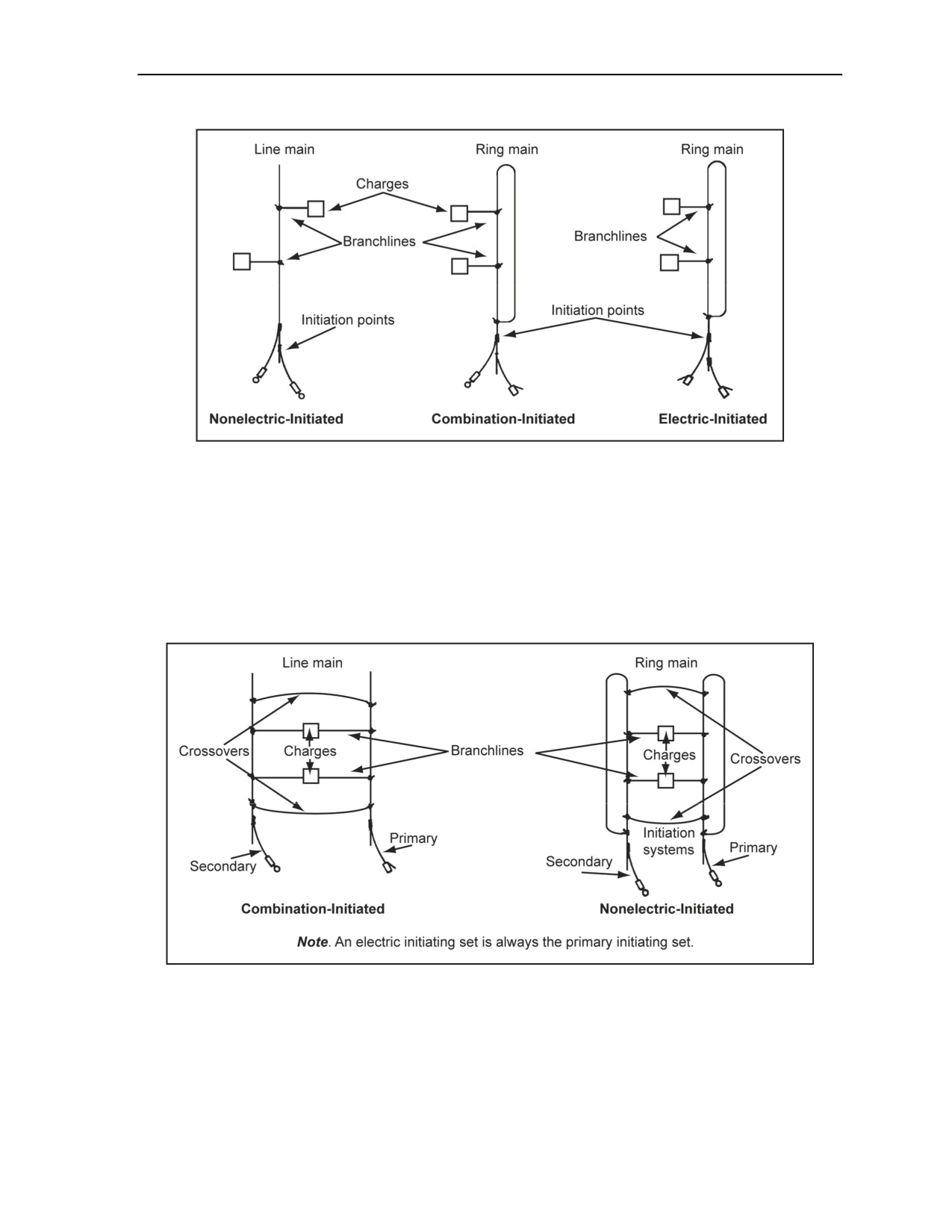
Initiating Sets, Priming Methods, Firing Systems, and Modernized Demolition Initiators
Figure 2-25. Single-Primed System (Dual-Initiated, Single-Fired, Single-Primed)
DUAL-PRIMED SYSTEM
2-49. Figure 2-26 shows a dual-primed system. Each charge is dual-primed with two branchlines
(Figure 2-27, page 2-26). One branchline is tied to one firing system, and the other branchline is tied to an
independent firing system. Line mains or ring mains may be used; however, they should not be mixed.
Detonating cord will be used as crossovers. Crossovers are used to tie both firing systems together at the
ends. The initiating sets are taped in with the primary initiating set going to one firing system and the
secondary going to the other.
Figure 2-26. Dual-Primed System (Dual-Initiated, Dual-Fired, Dual-Primed)
11 July 2007
FM 3-34.214
2-25
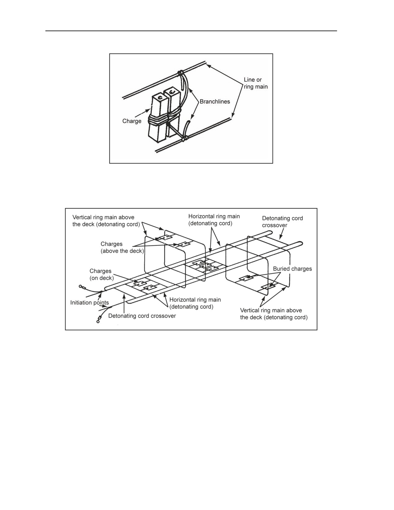
Chapter 2
Figure 2-27. Dual-Primed Charge
2-50. Figure 2-28 shows a dual-firing system using horizontal and vertical ring mains. The complexity of a
target or obstacle may necessitate using multiple line mains or ring mains for simultaneous detonation.
These are referred to as horizontal and vertical lines or ring mains.
Figure 2-28. Dual-Firing System (Using a Bridge as a Possible Target)
ATTACH THE BLASTING CAP
2-51. With tape, attach the electric or nonelectric blasting cap to the detonating cord. String, cloth, or fine
wire can be used if tape is not available. To overcome moisture contamination, tape the cap securely to a
point 6 inches from the end of the detonating cord. The tape must not conceal either end of the cap. Taping
in this way allows you to inspect the cap in case it misfires. No more than 1/8 inch of the cap needs to be
left exposed for inspection (Figure 2-29).
2-26
FM 3-34.214
11 July 2007
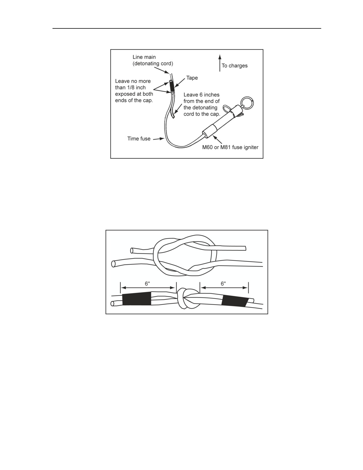
Initiating Sets, Priming Methods, Firing Systems, and Modernized Demolition Initiators
Figure 2-29. Attach a Blasting Cap to the Detonating Cord
CONNECT THE DETONATING CORD
2-52. Square knots or detonating cord clips are used to splice the ends of the detonating cord (Figure 2-30).
Always reinforce the splice with tape. Do not splice detonating cord on branchlines. Square knots may be
placed underwater or underground, but the cord must be detonated from a dry end or aboveground. To
prevent misfires from moisture contamination, allow 6-inch tails on square knots. Chapter 1, Section III,
describes the process for connecting detonating cord with detonating cord clips.
Figure 2-30. Square-Knot Connections for Detonating Cord
BRANCHLINE
2-53. A branchline is a length of detonating cord between the charge and the firing system. Branchlines
should be attached to a detonating cord ring or line main to fire multiple charges. Combining the branchline
with an initiating set allows a single branchline to be fired. A branchline should be fastened to a main line
with a detonating cord clip (Figure 1-16, page 1-21) or a girth hitch with an extra turn or a Gregory knot
(also known as a cherry knot) (Figure 2-31, page 2-28). The connections of branchlines and line or ring
mains should intersect at right angles. If these connections are not at right angles, the branchline may be
blown off the line main without complete detonation. To prevent moisture contamination and to ensure
positive detonation, leave at least 6 inches of the running end of the branchline beyond the tie. It does not
matter which side of the knot the 6-inch tail is on at the connection of the line or ring main.
11 July 2007
FM 3-34.214
2-27
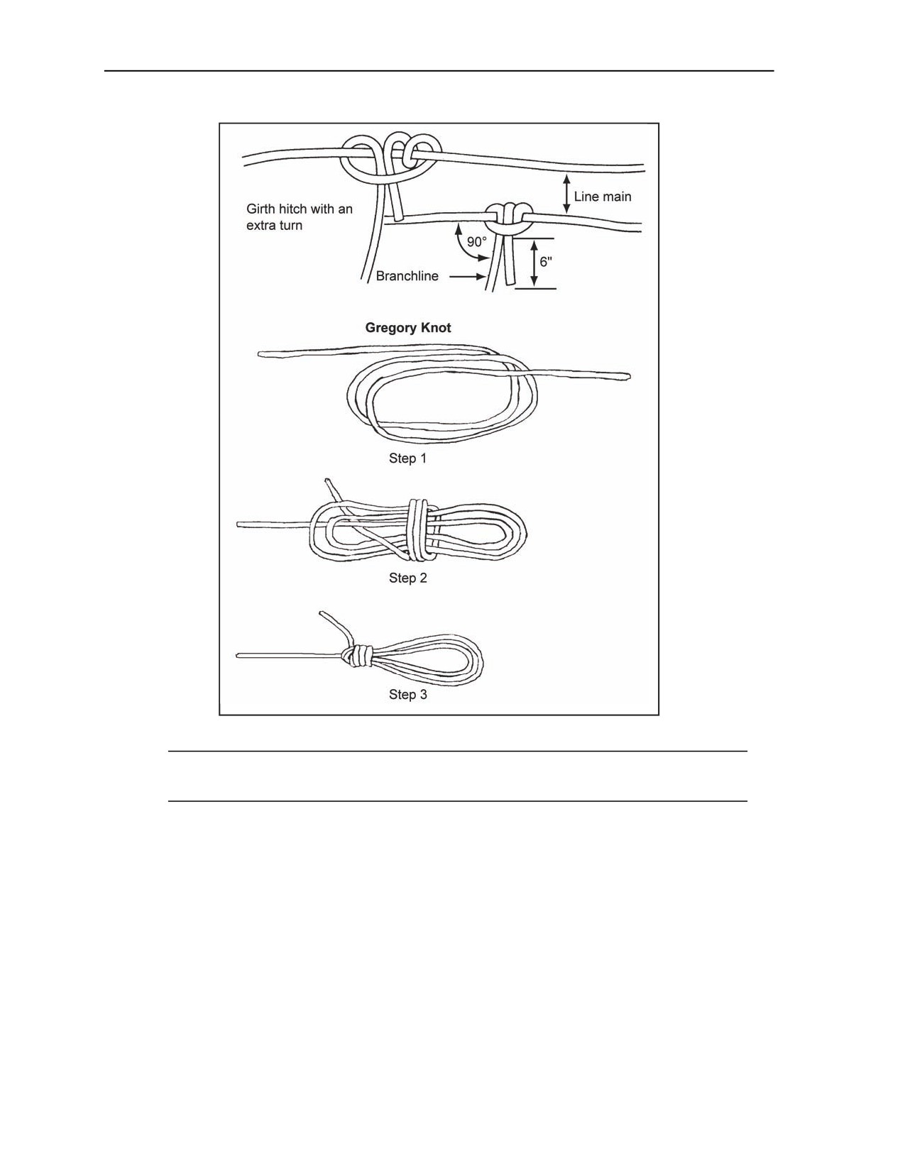
Chapter 2
Figure 2-31. Branchline Connections for Detonating Cord
Note. Nonelectric blasting caps can be crimped to detonating cord as well as time fuses. This
capability permits simultaneous firing of multiple charges primed with blasting caps.
LINE MAIN
2-54. A line main can fire a single charge or multiple charges (Figure 2-32), but if a break in the line
occurs, the detonating wave will stop at the break. When the risk of having a line main cut is unacceptable,
use a ring main. Line mains are used only when speed is essential. Any number of branchlines can be
connected to a line main. However, you connect only one branchline at any one point unless using a British
junction (Figure 2-33).
2-28
FM 3-34.214
11 July 2007
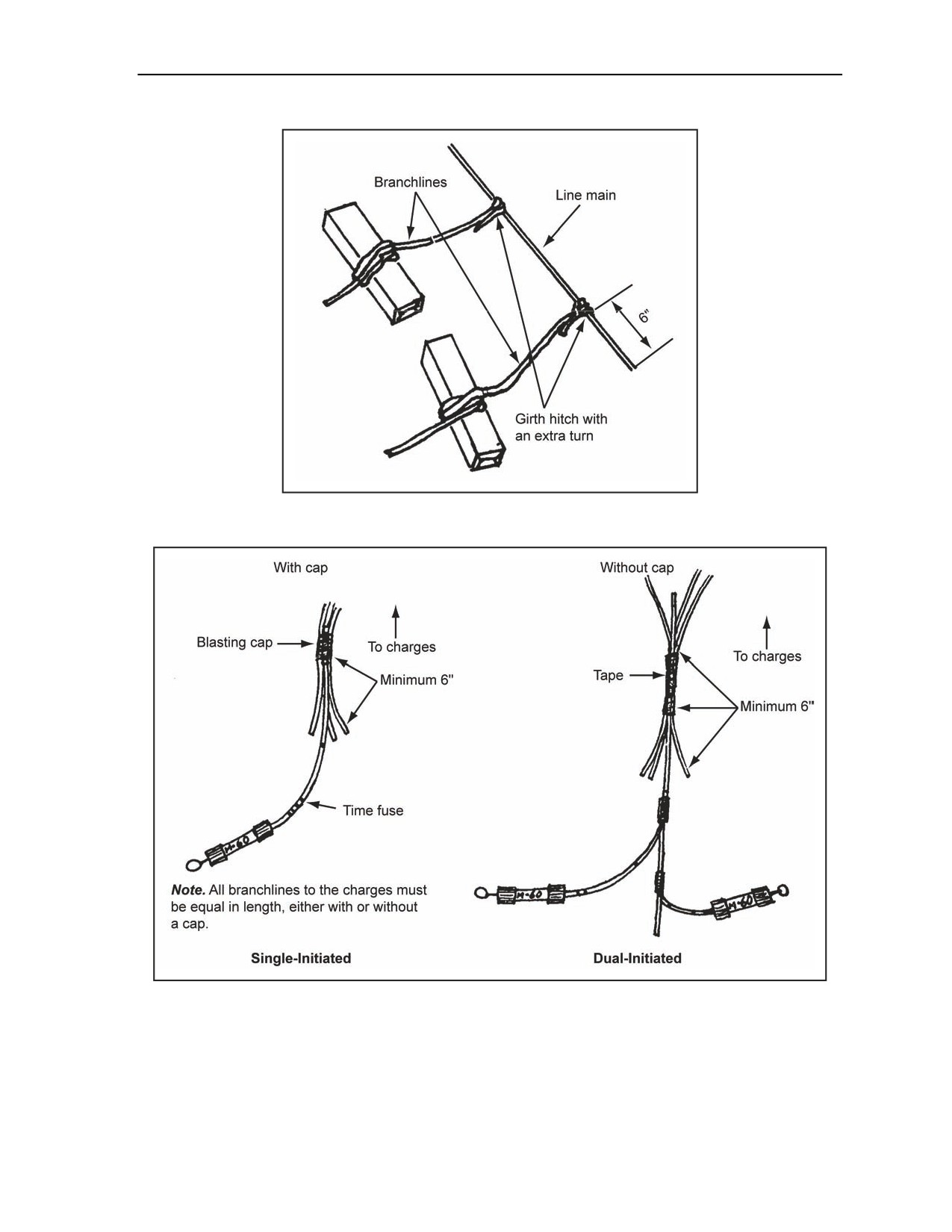
Initiating Sets, Priming Methods, Firing Systems, and Modernized Demolition Initiators
Figure 2-32. Line Main With Branchlines
Figure 2-33. Connecting With a British Junction
RING MAIN
2-55. Ring mains are preferred over line mains because the detonating wave approaches the branchlines
from two directions. The charges will detonate even when there is a break in the ring main. A ring main
will detonate an unlimited number of charges. Branchline connections to the ring main should be at right
11 July 2007
FM 3-34.214
2-29
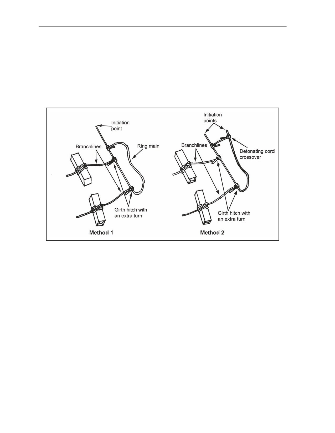
Chapter 2
angles. Kinks in the lines should not be sharp. Any number of branchlines can be connected to the ring
main; however, never connect a branchline (at the point) where the ring main is spliced. When making
branchline connections, avoid crossing lines. If a line crossing is necessary, provide at least 1 foot of
clearance between the detonating cords. Otherwise, the cords may cut each other and may destroy the firing
system. The methods below describe how to make a ring main (Figure 2-34).
Method 1. Make a ring main by bringing the detonating cord back in the form of a loop and
attach it to itself with a girth hitch with an extra turn.
Method 2. Make a ring main by making a U shape with the detonating cord, and then attach a
detonating cord crossover at the open end of the U. Use girth hitches with extra turns when
attach the crossover.
Figure 2-34. Ring Mains
INITIATE A FIRING SYSTEM
2-56. The two types of firing systems are the single-primed and dual-primed. Initiation of these is
described below.
SINGLE-PRIMED SYSTEM
2-57. A single line or ring main should be dual-initiated as shown in Figure 2-35. The blasting cap that will
detonate first should be placed closest to the end of the detonating cord (for example, the electric cap of a
combination of initiating sets). Doing this ensures the integrity of the backup system if the first cap
detonates and fails to initiate the line main.
2-30
FM 3-34.214
11 July 2007
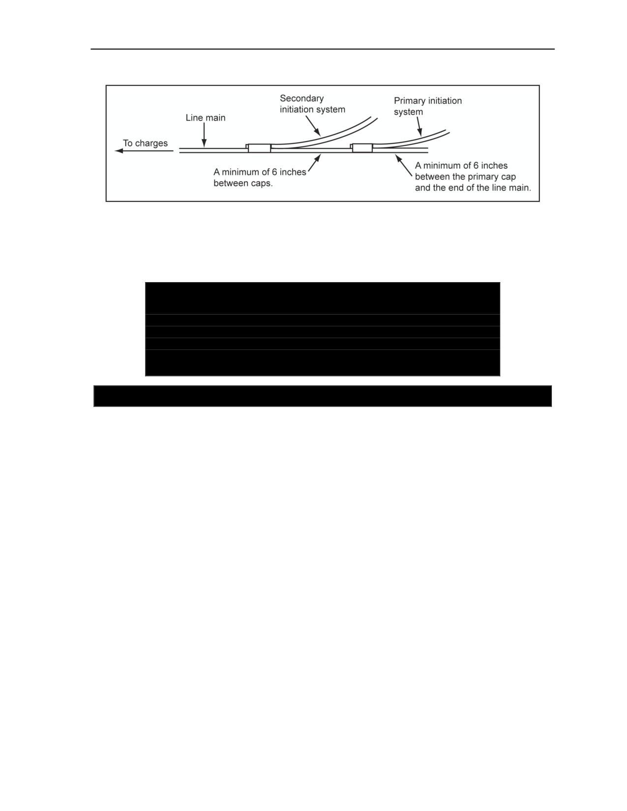
Initiating Sets, Priming Methods, Firing Systems, and Modernized Demolition Initiators
Figure 2-35. Attaching Blasting Caps to a Line Main
DUAL-PRIMED SYSTEM
2-58. A dual-primed system is initiated as shown in Figure 2-26, page 2-25. However, the blasting caps are
still connected as shown in Figure 2-29, page 2-27.
DANGER
When using a time or safety fuse, uncoil it and lay it out in a
straight line. The time fuse should be placed so that the fuse will
not curl up and prematurely detonate the blasting cap crimped to
it. Failure to comply may cause death or permanent injury.
SECTION IV - MODERNIZED DEMOLITION INITIATORS
CHARACTERISTICS
2-59. The MDI is the project name given to a new family of nonelectric blasting caps, nonelectric boosters,
and associated items. MDIs supplement and partially replace the M7 nonelectric blasting cap, the M6
electric blasting cap, and the M700 time fuse. The snap-together MDI components simplify initiation
systems and some types of explosive priming. In some cases, emplacement times can be decreased by up to
50 percent. MDIs also improve reliability and safety. One reason for this reliability is the fact that all of the
components are sealed and, unlike standard nonelectric-priming components, cannot be easily degraded by
moisture. However, once the system has been spliced, reliability is significantly degraded due to moisture.
The sealed MDI components can be emplaced 70 feet underwater.
SHOCK TUBE
2-60. The shock tube is a thin, plastic tube of extruded polymer with a dusting of cyclotetramethylene
tetramitramine (HMX) and aluminum powder deposited on its interior surface. This special explosive dust
propagates a detonation wave. The wave moves along the shock tube to a factory crimped and sealed
blasting cap (which is moisture resistant). The detonation is normally contained within the plastic tubing,
and if strands of tubing touch or cross over each other there is no concern that an inadvertent ignition would
occur. Fragments from blasting caps or other explosive charges travel at speeds three to five times faster
than the detonating wave in the shock tube. These fragments could cause damage to other shock tube
assemblies. Any puncture in the shock tube in front of the dust explosion provides a path for the explosive
wave to vent. The shock tube offers the instantaneous action of electric initiation without the risk of
accidental initiation of the blasting cap (and the charge) by radio transmitters in the area or by static
electricity discharge. The shock tube medium is extremely reliable.
11 July 2007
FM 3-34.214
2-31

Chapter 2
WARNING
Although the detonation along the shock tube is normally
contained within the blasting tubing, burns may occur if the
shock tube is held. Failure to comply could result in immediate
personal injury or damage to equipment.
Note. To prevent misfire, MDIs used at high altitude must be precut and a temporary moisture
seal applied to the ends before moving from low altitude to high altitude. This action prevents
the HMX from escaping the shock tube when cut at high altitudes due to the air pressure
difference between the inside of the shock tube and the surrounding atmosphere.
WARNING
Never attach an M81 until ready to attach the system. Failure to
comply could result in immediate personal injury or damage to
equipment.
2-61. Shock tube functioning is usually evident by a bright flash within the tube. The flash is well
contained by the olive drab coating but can be seen in the clear coating of military shock tubes. The flash
can produce a burn if a piece of shock tube is held when it is functioning, even through the coating of the
shock tube. Therefore, never hold a shock tube while detonating an explosive system. The free end of the
shock tube blasting cap is always sealed. Cutting the shock tube exposes the open ends to moisture and
should only be done if absolutely necessary. Dampening the explosive dust on the inside of the shock tube
will stop a detonation from going beyond such a damp spot. Care should be used when cutting shock tubes.
When cutting a shock tube, a sharp knife or other single blade should be used to produce a square cut.
Never use pliers, crimpers, or scissors when cutting shock tube because they will cause narrowing of the
small diameter hole in the shock tube. Any narrowing or overlapping of the hole could block the explosive
path and result in a failure to ignite the explosive dust in the shock tube.
BLASTING CAPS
2-62. Military explosives require a substantial shock to be initiated. This shock is provided by a high-
strength blasting cap (nonelectric M7 or the electric M6). To replace the M6 and M7, there are high-
strength and low-strength MDI blasting caps. Each blasting cap is factory crimped and sealed, making them
extremely reliable.
High-Strength Caps
2-63. High-strength caps include the M11, M14, M15, M18, M19, M21, and M23. All are nonelectric and
come with a length of shock tube attached. The function of the shock tube is to transfer a small initiating
impulse to the explosive end of the cap (an explosive-filled aluminum tube or detonator), which produces a
detonation shock strong enough to initiate military explosives. Cap characteristics are as follows:
The M11 cap comes with a 30-foot length of shock tube factory-attached to a military-sized
aluminum blasting cap tube. The M11 is essentially instantaneous in its action. The M11 has a
plastic connector on the free end of its shock tube called a detonating cord clip. The detonating
cord clip facilitates quick and easy attachment onto the detonating cord.
The M14 consists of a military strength and size nonelectric blasting cap, factory-crimped to a
factory-calibrated, nominal 5-minute length of M700 time-blasting fuse.
The M15 has pyrotechnic (used to introduce a delay into an explosive train because of its known
burning time [the definition was shortened, and the complete definition is printed in the
glossary]) (FM 1-02) (JP 1-02) devices installed to provide a small time delay between its
2-32
FM 3-34.214
11 July 2007

Initiating Sets, Priming Methods, Firing Systems, and Modernized Demolition Initiators
initiation and the firing of its detonators. The M15 has two detonators. One detonator is low
strength with a 25-millisecond delay, and the other is high strength with a 200-millisecond
delay.
The M18 consists of a military strength and size nonelectric blasting cap, factory-crimped to a
factory-calibrated, nominal 20-minute length of M700 time-blasting fuse.
The M19 consists of a 200-foot length of dual minitube with an in-line initiator built into one
end of each of the two minitubes and a nonelectric, nondelay high-strength blasting cap attached
to the other end of each minitube. The minitube is smaller in diameter and possesses all the same
characteristics of shock tube. The M81E1 igniter is attached to each in-line initiator.
The M21 consists of a high-strength blasting cap precrimped to a 500-foot length of minitube.
The M21 is about one-third the size and weight of the existing M12. The M81E1 igniter is
attached to the in-line initiator.
The M23 consists of a high-strength blasting cap precrimped to a 1,000-foot length of minitube.
The M23 is about one-third the size and weight of the existing M13. The M81E1 igniter is
attached to the in-line initiator.
Note. All high-strength caps will be in the original packaging or a protective foam cylinder when
carried by Soldiers.
Low-Strength Caps
2-64. The M12 and M13 are the two low-strength MDI blasting caps. These relay-type blasting caps come
with factory-attached lengths of shock tube (500 feet for the M12 and 1,000 feet for the M13). The
detonators of the relay-type caps are purposely made larger than standard military blasting caps (and the
high-strength MDI blasting caps) so they will not fit in standard cap wells. It is important to remember that
the low-strength, relay-type caps (such as the M12 and M13) cannot reliably set off standard military
explosives. However, low-strength caps of the MDI M12 and M13 will reliabily initiate detonating cord.
Boosters
2-65. The M151 is a nonelectric, insensitive initiation system that is factory-assembled. It is assembled by
crimping a secondary explosive booster onto a 10-foot length of low-strength detonating cord to allow the
user to preprime explosives for military operations and bury explosives primed with M151. The M151 has
a detonating cord clip like other MDI components for easy attachment to a line or ring main detonating
cord. A pentagonal-shaped tag affixed to the low-strength detonating cord identifies it as an M151 to
preclude incorrect connection within a firing system.
2-66. The M152 is a nonelectric, insensitive initiation system that is factory-assembled. It is assembled by
crimping a secondary explosive booster onto a 30-foot length of low-strength detonating cord to allow the
user to preprime explosives for military operations and bury explosives primed with M152. The M152 has
a detonating cord clip like other MDI components for easy attachment to a line or ring main detonating
cord. A pentagonal-shaped tag affixed to the low-strength detonating cord identifies it as an M152 to
preclude incorrect connection within a firing system.
M9 BLASTING-CAP HOLDER
2-67. Plastic holders allow the connection of several shock tubes to high-strength blasting caps and
boosters. The M9 holder helps secure the connection of up to five shock tubes or low-strength detonating
cord to high-strength caps or boosters. The M9 holder can also be used to connect high-strength blasting
caps and boosters to detonating cord. When using the M9 holder, tape it closed.
11 July 2007
FM 3-34.214
2-33

Chapter 2
WARNING
Do not connect the shock tube, low-strength detonating cord, or
detonating cord in the same holder. Detonating cord functions at
a higher velocity than the HMX and aluminum in the shock tube
and may cause a break in the shock tube. Failure to comply could
result in immediate personal injury or damage to equipment.
M81 TIME-BLASTING FUSE IGNITER
2-68. The igniter will initiate the time fuse and shock tube end of MDI components. The M81 is almost
identical to the older M60 igniter, except the M81 has a screw-end cap with a green shipping plug and a
silicon shock tube reducer. The cap allows the M81 to accommodate either a standard shock tube or a
standard diameter time-blasting fuse (M700). Extra care is required when connecting a shock tube to an
M81 igniter to ensure proper initiation of an explosive system.
WARNING
Never attach detonating cord, an M151, or an M152 to the M81
igniter. Failure to comply could result in immediate personal
injury or damage to equipment.
M11 NONELECTRIC BLASTING CAP WITH A 30-FOOT SHOCK
TUBE
2-69. The M11 is a high-strength blasting cap, factory-crimped to a 30-foot length of shock tube. A
movable plastic connector (a detonating cord clip) is attached to the free end of the shock tube. The hook
allows for a quick and easy attachment to a detonating cord. Two brightly colored plastic flags are attached
to the shock tube near the blasting cap. A red flag is attached 1 meter from the blasting cap, and a yellow
flag is attached
2 meters from the blasting cap. M11s are packaged with an issue of six M11s per
subpackage as shown in Figure 2-36. Subpackages maintain the same hazard classification as the wooden
crate.
2-34
FM 3-34.214
11 July 2007
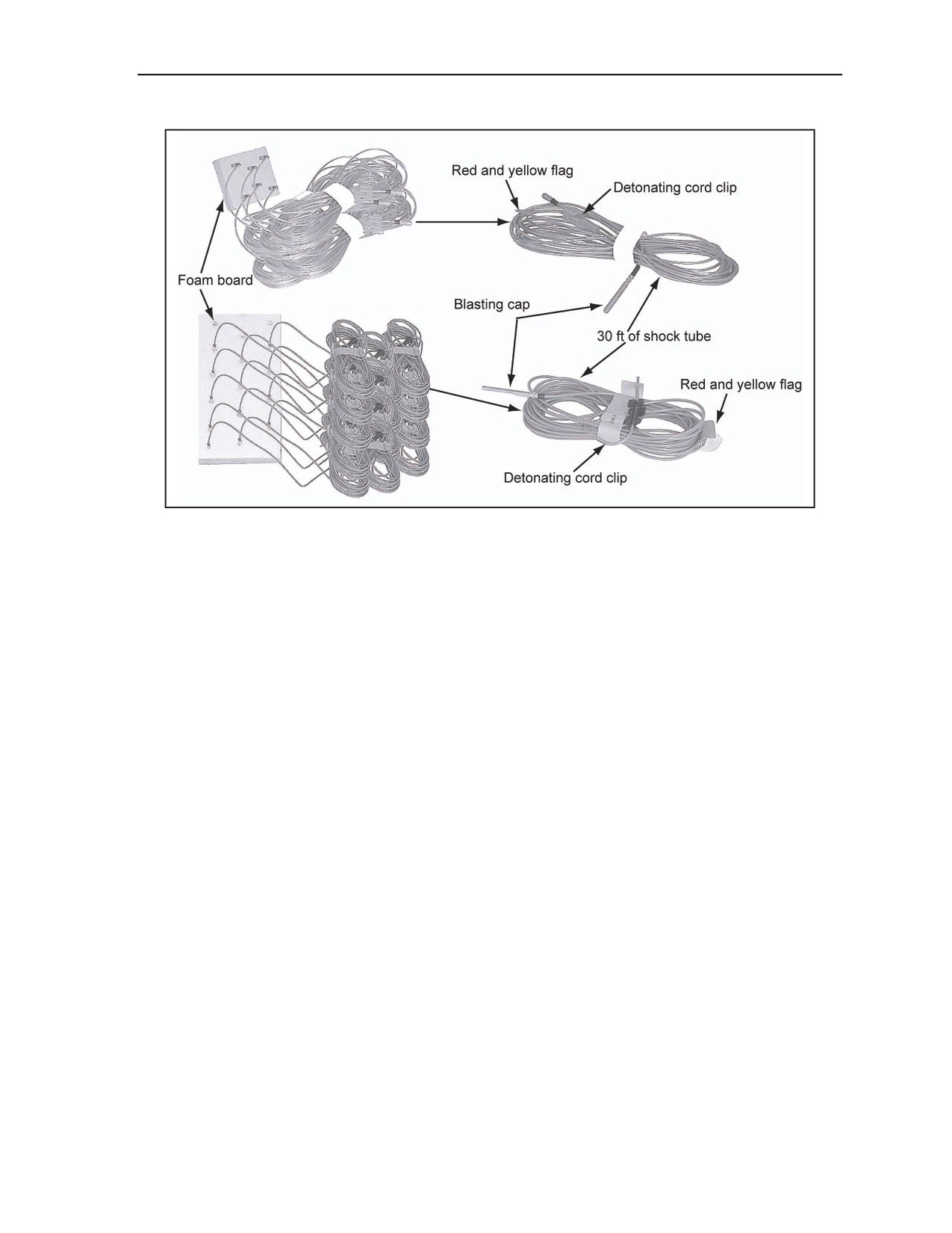
Initiating Sets, Priming Methods, Firing Systems, and Modernized Demolition Initiators
Figure 2-36. M11 Blasting Cap Component (Various Vendors)
USE
2-70. The M11 can be used to prime standard military explosives. The M11 can also be used to initiate
detonating cord or shock tube.
FUNCTIONS
2-71. The M11 functions by sending an initiating shock or small detonation through the shock tube to the
blasting cap. The shock tube itself must be initiated by a relay-type blasting cap, booster, or igniter (M81).
The M11’s detonation is instantaneous. See Table 2-1, page 2-36, for the M11 characteristics.
11 July 2007
FM 3-34.214
2-35

Chapter 2
Table 2-1. M11 Characteristics
Tabulated Data
Length
2.25 to 2.35 in
Aluminum-tube detonator
Diameter
0.241 in
Material
Various plastics
Shock tube
Length
30 ft
Diameter
0.118 in
Lead azide, molybdenum chromate, RDX, or
Detonator
PETN
Filler
Shock tube
HMX and aluminum
Shock from the detonation of a blasting cap or
Actuation method
detonating cord
Shipping and Storage Data
DOD hazard class
1.4S
QD/DIV/SCG
DOT hazard class
1.4S
DOT label
Explosive
1.4S
Proper shipping
Detonator assemblies, nonelectric for blasting
name
UN serial number
0500
NSN
1375-01-415-1232
DOT container marking
DODAC
Live: ML47
Inert: MN36
NEW
19 gr
(per cap)
Specification
QAA-1423
Packaging
60 units per wood box; 16 boxes per pallet
Dimensions
20.5 by 13 by 25.75 in
Cube
2.8 cu ft
Packing box
NEW
0.16 lb
Gross weight of
49 lb
package
References
TM 9-1375-213-34&P
DOD Consolidated Ammunition Supply Catalog
M12 NONELECTRIC BLASTING CAP WITH A 500-FOOT SHOCK
TUBE
2-72. The M12 is a low-strength blasting cap, factory-crimped to a 500-foot length of shock tube. A special
plastic connector is attached to the detonator to facilitate a quick and easy attachment to the shock tube of
up to five shock tubes or five low-strength detonating cords or one strand of standard detonating cords. The
M12 is provided on a spool as shown in Figure 2-37.
2-36
FM 3-34.214
11 July 2007
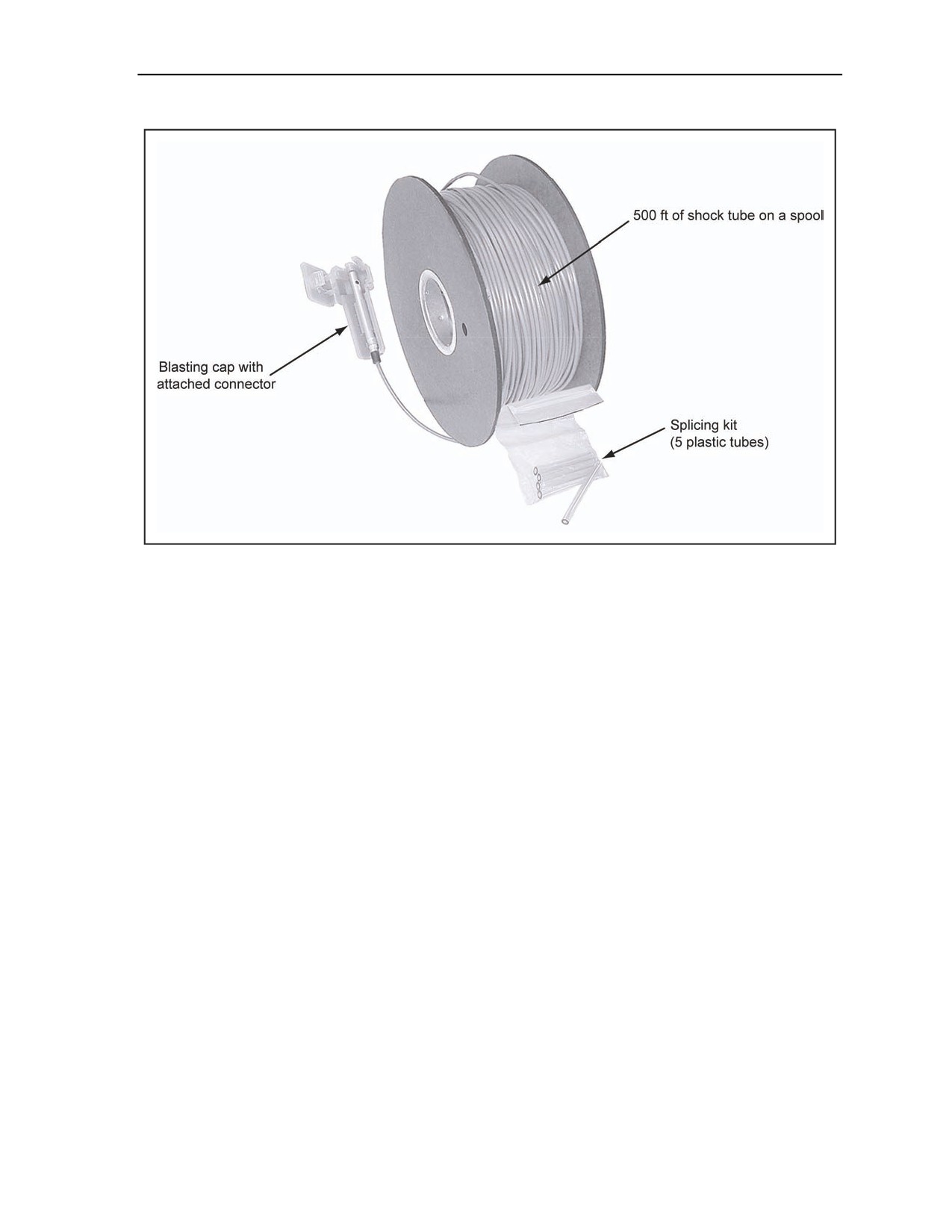
Initiating Sets, Priming Methods, Firing Systems, and Modernized Demolition Initiators
Figure 2-37. M12 Shock Tube Component and Blasting Cap With a Splicing Kit
USE
2-73. The M12 is used as a transmission line in a firing system. It does not have enough output to initiate
military explosives reliably.
FUNCTIONS
2-74. The M12 functions by sending an initiating shock or small detonation through the shock tube to the
blasting cap. This blasting cap then actuates five shock tubes, five low-strength detonating cords, or one
strand of high-strength detonating cord held by the plastic connector. The M12’s shock tube must be
initiated by another blasting cap or by the M81 fuse igniter. Table
2-2, page
2-38, shows the
M12characteristics.
11 July 2007
FM 3-34.214
2-37

Chapter 2
Table 2-2. M12 Characteristics
Tabulated Data
Aluminum-tube
Length
2.7 in
detonator
Diameter
0.296 in
Material
Various plastics
Shock tube
Length
500 ft
Diameter
0.118 in
Detonator
Lead azide, PETN
Shock tube
HMX and aluminum
Filler
Shock from detonation of a blasting cap or the
Actuation method
primer in an M81
Shipping and Storage Data
DOD hazard class
1.4S
QD/DIV/SCG
DOT hazard class
1.4S
DOT label
Explosive
1.4S
Proper shipping name
Detonators, nonelectric
UN serial number
0500
NSN
1375-01-415-1230
DODAC
Live: MN02
Inert: MN35
NEW (per cap)
13 gr
DOT container marking
Drawing
12972628
Specification
QAA-1459
Pre-1999: 8 units per fiberboard box; 6 boxes (48
units) per wooden box
Packaging
Post-1999: 8 units per fiberboard box; 5 boxes
per wooden box (40 units)
Pre-1999: 46 by 21 by 21 in
Dimensions
Post-1999: 48.75 by 19.8 by 20.75 in
Pre-1999: 11.74 cu ft
Cube
Post-1999: 11.6 cu ft
Packing box
Pre-1999: 0.286 lb
NEW
Post-1999: 0.239 lb
Pre-1999: 169 lb
Gross weight of package
Post-1999: 176 lb
References
TM 9-1375-213-34&P
DOD Consolidated Ammunition Supply Catalog
M21 NONELECTRIC BLASTING CAP WITH A 500-FOOT
MINISHOCK TUBE
2-75. The M21 consists of a high-strength blasting cap precrimped to a 500-foot length of minitube. The
M21 is about one-third the size and weight of the M12. The M21 has a modified M81E1 igniter moisture
2-38
FM 3-34.214
11 July 2007
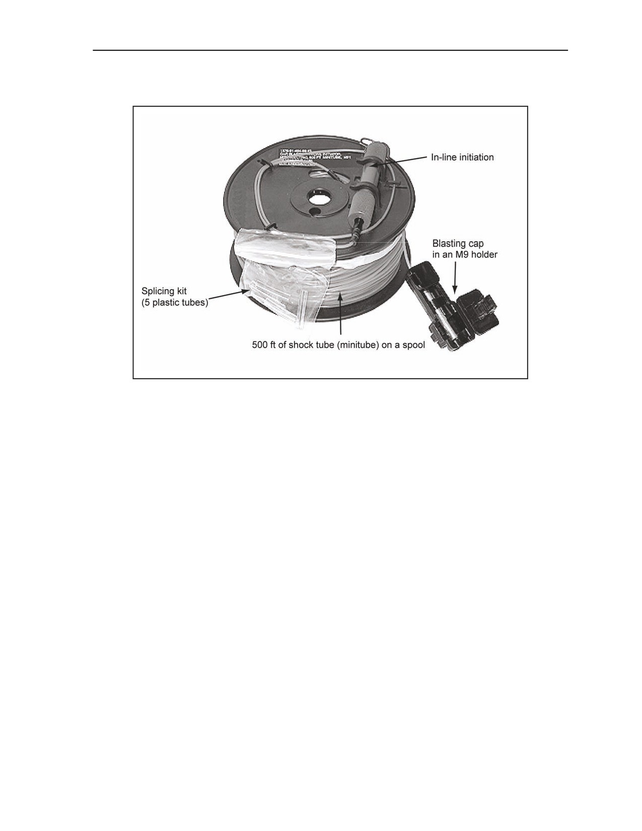
Initiating Sets, Priming Methods, Firing Systems, and Modernized Demolition Initiators
cap with a protected ignition primer that is factory-installed to an in-line initiator on the minitube. The M21
has an M9 holder already connected to the high-strength cap (Figure 2-38).
Figure 2-38. M21 MDI With a 500-Foot Shock Tube Component With a Splicing Kit
USE
2-76. The M21 is used to transmit a shock tube detonation impulse from an initiator (or another relay cap).
Unlike the M12, a high-strength blasting cap or booster will not have to be added as part of the
transmission line. The M21 high-strength cap can be secured into an M9 holder to provide the capability to
initiate up to five additional shock tubes or five low-strength detonating cords or one strand of detonating
cord. The M21 high-strength cap can also be used to prime military explosives.
FUNCTIONS
2-77. The M21 functions by sending an initiating shock or small detonation through the shock tube to the
blasting cap. This blasting cap then actuates five shock tubes, five low-strength detonating cords, or one
strand of high-strength detonating cord held by the plastic connector. The M21’s shock tube must be
initiated by another blasting cap or by the M81E1 in-line initiators. Table 2-3, page 2-40, shows the M21
characteristics.
11 July 2007
FM 3-34.214
2-39
//////////////////////////////////////////