Operation, Maintenance Manual, and Logbook for Propeller Systems HM-5V1-B1000-A, HM-6V1-A1000-A (2018) - page 3
Page 4-4
Rev. 3 Apr/17
TESTING AND TROUBLESHOOTING
OPERATION, MAINTENANCE MANUAL, AND LOGBOOK
300
2. Troubleshooting
A. Surging
(1) Surging is characterized by a large increase/decrease in engine speed,
followed by a return to set speed after one or two occurrences.
(a) Check for trapped air in the propeller
1
Complete steps 1.A.(1) through 1.A.(6) under the Operational Tests
section in this chapter to release trapped air from the propeller.
(b) Check
the blades for excessive friction. If present:
1
Inspect the blade retention system.
(c) Check tachometer for oscillation. If present:
1
Inspect the tachometer and drive.
(d) Check for sludge and dirt deposits.
1
Inspect and clean the propeller, beta valve, cylinder, and oil tubes.
(e) Check the connection from the beta valve to the actuator.
B. Pitch Change Sluggish
(1) Inspect the blade retention system for excessive friction.
(2) Check the oil pressure and flow (for low pressure).
(a) Inspect the oil supply and oil transfer openings.
(3) Inspect the beta tube passages for dirt deposits.
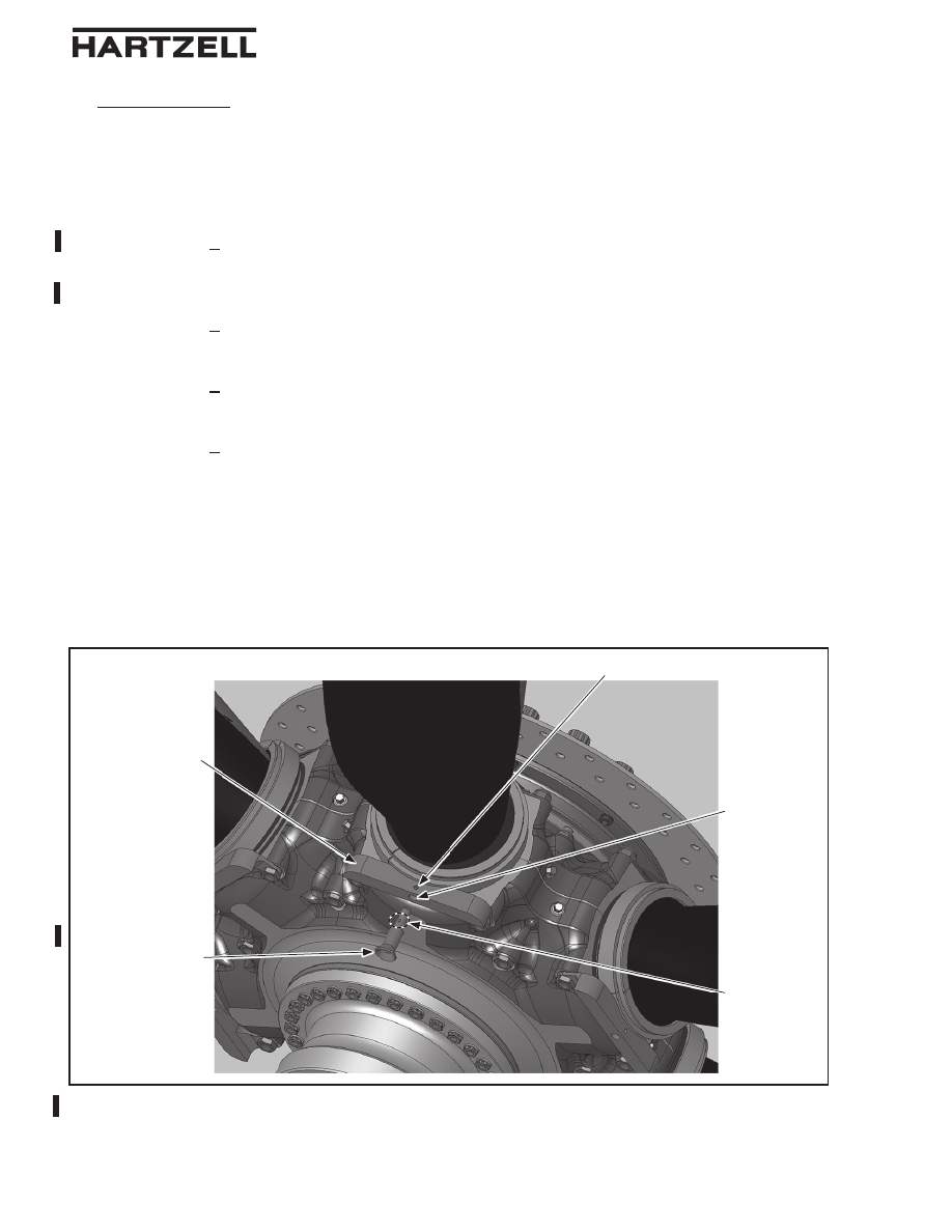
Pitch Lock Pin Installation
Figure 4-1
Pitch Lock
Bracket
Pitch Lock
Hole
Locking
Balls
103155
Pitch Lock Pin
Witness Hole
TI-300-002
Page 4-5
Rev. 3 Apr/17
TESTING AND TROUBLESHOOTING
OPERATION, MAINTENANCE MANUAL, AND LOGBOOK
300
C. Loss of Thrust
(1) Inspect the hydraulic system for proper function.
WARNING: HOVERCRAFT OPERATION WITH THE 103155 PITCH LOCK
PINS INSTALLED WILL NOT PERMIT THRUST REVERSING
FUNCTION TO SLOW THE VEHICLE.
(a) If the hydraulic propeller pitch control system has failed, install the
103155 pitch lock pins to lock the propeller into a single pitch, permitting
a restricted mode of operation. Refer to Figure 4-1.
1
Shut down propeller thrust engines.
2
Remove any ice (or debris) in/over pitch lock holes.
CAUTION:
DO NOT DAMAGE THE LEADING OR TRAILING
EDGES OF THE BLADE WHEN DOING THE
FOLLOWING STEP.
3
Manually force the pitch of the propeller blades to a position where
the pitch lock bracket hole lines up with the hole in the blade ring.
a This
could require two crewmen to apply force to two separate
blades at the same time.
4
Push and hold the button on the 103155 pitch lock pin while putting
the pin into the pitch lock hole on the pitch lock bracket.
a
Push the 103155 pitch lock pin into the pitch lock hole until the
locking balls are lined up with the witness hole in the bracket,
then release the button on the pin.
(1) After releasing the button on the 103155 pitch lock pin,
move the pin until the locking balls "click" into the holes in
the pitch lock bracket.
CAUTION: DO NOT PUSH THE BUTTON ON THE 103155
PITCH LOCK PIN WHEN CHECKING THE PIN
INSTALLATION.
b
Pull the 103155 pitch lock pin to make sure it is locked into the
pitch lock bracket.
(1) If the 103155 pitch lock pin pulls out of the pitch lock
bracket, repeat 2.C.(1)(a)4 through 2.C.(1)(a)4 b.
c
Repeat steps 2.C.(1)(a)4 through 2.C.(1)(a)4 a(1) for
each blade.
5
Re-start the propeller thrust engines.
6 Operate
the Hovercraft propeller thrust engines within their limits of
RPM range.
a
Allow sufficient distance to slow and maneuver the Hovercraft.