Operation, Maintenance Manual, and Logbook for Propeller Systems HM-5V1-B1000-A, HM-6V1-A1000-A (2018) - page 2
Page 3-6
Rev. 1 Sep/13
INSTALLATION AND REMOVAL
OPERATION, MAINTENANCE MANUAL AND LOGBOOK
300
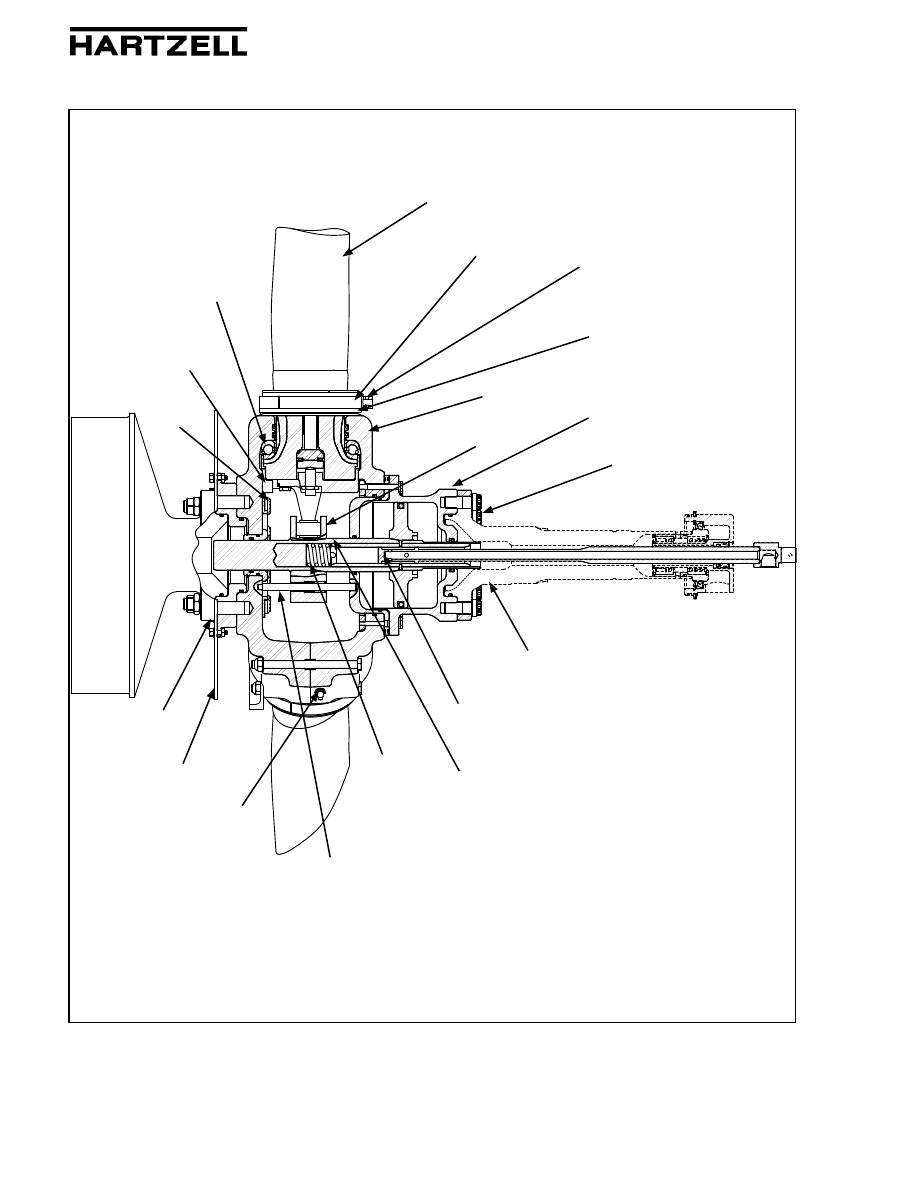
Propeller System Components
Figure 3-1
Blade
Hub
Blade Retention
Bearing
Preload Plate
Lubrication
Fitting -
5 Blade Only
Fork
Stub Shaft
Flange
Beta Tube
Assembly
Pitch Change
Rod
Mounting Bolt
Engine Flange
Mounting
Stud
Pitch
Change
Rod Spring
Balance Ring
Cylinder
Pitch Lock
Bracket
Anti-rotation Rod
TI-300-001
5 Blade Propeller shown for reference
Pitch Lock Ring
Blade Seal
Page 3-7
Rev. 1 Sep/13
INSTALLATION AND REMOVAL
OPERATION, MAINTENANCE MANUAL AND LOGBOOK
300
2. Propeller Assembly Pre-Installation
A. Inspection of Shipping Package
(1) Examine the exterior of the shipping container for signs of shipping damage,
especially at the box ends around each blade.
(2) A hole, tear, or crushed appearance at the end of the box (at the propeller tips)
may indicate the propeller was dropped during shipment, possibly damaging
the blades.
B. Uncrating
(1) Place the propeller container on a firm support.
(2) Remove the banding and any external wood bracing from the shipping
container.
(3) Remove the blades from the cardboard box.
(4) Remove the hub from the wooden container.
CAUTION:
DO NOT STAND THE PROPELLER ON A BLADE TIP.
(5) Put the propeller on a padded surface that supports the entire length of the
propeller.
(6) Remove the plastic dust cover cup from the propeller mounting flange, if
installed.
C. Inspection after Shipment
(1) After removing the propeller from the shipping container, examine the propeller
components for shipping damage.