JEPPESEN GENERAL AIRWAY MANUAL (Issue Date 1 JUL 21) - page 9
 

  Index      Manuals     JEPPESEN GENERAL AIRWAY MANUAL (Issue Date 1 JUL 21)


Search            copyright infringement  


Content      ..     7      8      9      10     ..


JEPPESEN GENERAL AIRWAY MANUAL (Issue Date 1 JUL 21) - page 9


Safedock Procedures (continued)

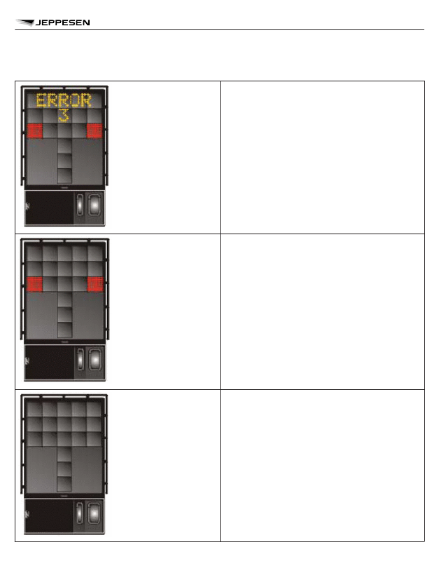
Error:
If a system error occurs, the message “ER-
ROR” is displayed with an error code. The code
is used for maintenance purposes.

System Breakdown:
In case of a severe system failure, the display
will go black, except for a red stop indicator. A
manual backup procedure must be used for
docking guidance.

Power Failure:
In case of a power failure, the display will be
completely black. A manual backup procedure
must be used for docking guidance.

VISUAL DOCKING GUIDANCE SYSTEMS (VDGS)

257

VISUAL DOCKING GUIDANCE SYSTEMS (VDGS)

VISUAL DOCKING GUIDANCE SYSTEMS (VDGS)

258

VISUAL DOCKING GUIDANCE SYSTEMS (VDGS)

SAFEGATE Docking System

The SAFEGATE docking display is aligned for interpretation from the left pilot's seat only and
provides centerline and stop guidance.

VISUAL DOCKING GUIDANCE SYSTEMS (VDGS)

259

VISUAL DOCKING GUIDANCE SYSTEMS (VDGS)

Docking maneuver:

a. Line-up to center aircraft symbol with green reference bar.
b. Check aircraft type displayed (flashing).

c. Check green bottom lights (flashing). When nosegear passes over first sensor, aircraft type

display and green bottom lights will both change from flashing to steady.

d. Green closing rate lights will move upwards in relation to actual aircraft speed.
e. At 1m before the stop position, yellow lights will illuminate.

f. Reaching the stop position, all 4 red lights will illuminate concurrent with the displayed com-

mand STOP.
If correctly positioned, OK will be displayed.

g. Beyond 1m of the nominal stop position, a warning will be displayed TOO FAR (flashing).
h. Emergency stop: All 4 red stop position lights and STOP will flash.

SYSTEMS PROVIDING CENTERLINE GUIDANCE ONLY

Azimuth Guidance for Noise-in Stands (AGNIS)

AGNIS provides stand centerline alignment guidance and is normally used in conjunction with
marker boards, lines or mirrors, which provide stopping guidance separately. The AGNIS indica-
tor is mounted at pilot eye level beneath the stand number and is aligned for interpretation from
the left pilot's seat only. The unit displays 2 closely spaced vertical light bars in red and/or green
light in such a manner that the pilot sees either:

Green

= aircraft on centerline

Red/green

= aircraft to the left of centerline

Green/red

= aircraft to the right of centerline

NOTE: Always turn towards the green.

VISUAL DOCKING GUIDANCE SYSTEMS (VDGS)

260

VISUAL DOCKING GUIDANCE SYSTEMS (VDGS)

CAUTION: The AGNIS guidance unit does NOT provide a stopping signal. The type of
stopping guidance used in conjunction with AGNIS will be indicated (e.g. Parallax Aircraft
Parking Aid [PAPA]) above or adjacent to the AGNIS.
In some cases a black base board is attached to the face of the pier under the AGNIS. In case of
system unserviceability, a STOP SHORT sign is displayed to the aircraft immediately. Use cau-
tion and follow marshaller's signals as appropriate.
AGNIS may be supported by one of the following aids:

– PAPA;
– Mirror.

VISUAL DOCKING GUIDANCE SYSTEMS (VDGS)

261

VISUAL DOCKING GUIDANCE SYSTEMS (VDGS)

SYSTEMS PROVIDING STOP GUIDANCE ONLY

Mirror System

The Mirror System consists of a mirror mounted to the left of the stand centerline and facing the
approaching aircraft. The mirror is angled so that the pilot in the left hand seat can see the re-
flection of the aircraft nose wheel during the last few meters of the parking maneuver. The cor-
rect stopping position is indicated by aircraft type designators painted in mirror image on the
apron surface. As the aircraft approaches, the pilot is able to see in the mirror a reflection of the
aircraft nose wheel and an appropriate designator where the aircraft should be stopped. A yellow
javelin headed arrow may be used as the designator, with the aircraft type given.

Parallax Aircraft Parking Aid (PAPA)

The system is designated for use from the left pilots position. This aid is normally positioned to
the right side of the stand centerline and indicates the correct forward stopping position by em-
ploying a black board marked with white vertical lines bearing aircraft type identification labels
and in which a horizontal slot has been cut.
A short distance behind the slot is a vertically mounted white fluorescent light tube.
The accuracy of this system depends on the accuracy of the of stand centerline.
Aircraft type line indicates the stop point. An alternative layout is illustrated also, where the board
is not provided with a slot and the tube is mounted in front of it. The method of use is identical.

VISUAL DOCKING GUIDANCE SYSTEMS (VDGS)

262

VISUAL DOCKING GUIDANCE SYSTEMS (VDGS)

WARNING:
Under certain daylight conditions difficulty may be experienced in observing the fluorescent tube
through the slot.

Side Marker Board (SMB)

The SMB consists of a white base board on the pier side of the air jetty and vertical slats moun-
ted on the face of the base board. It stands parallel to the stand centerline flush with the head of
the air jetty in its retracted position.
The edge of each slat is black, the side facing the taxiway is green, and the side facing the pier
is red. Each slat has a name tab(s) attached at appropriate pilot eye level to indicate the aircraft
type(s) to which the slat applies. As the pilot enters the stand, the slat bearing tab appropriate to
his aircraft type presents the green side. As the pilot approaches, the green side will appear to
become narrower, and when the correct stop position is reached, pilot will see the black edge
only. If the correct stop position is passed, the red side of the slat will come into view. It is advis-
able to approach the stopping position slowly.
The DC9 aircraft, which stops with the pilot's position abeam the air jetty head will not be served
by the SMB. In this case the correct stopping position for this aircraft will consist of a mark on the
air jetty itself.

VISUAL DOCKING GUIDANCE SYSTEMS (VDGS)

263

VISUAL DOCKING GUIDANCE SYSTEMS (VDGS)

One Slot Example

NOTE: When SMB is unserviceable, aircraft must be marshalled.

VISUAL DOCKING GUIDANCE SYSTEMS (VDGS)

264

VISUAL DOCKING GUIDANCE SYSTEMS (VDGS)

Chart Change Notices

Chart Change Notices

NavData Change Data

Jeppesen Airway Manual Charts are the same publications which Jeppesen has provided
to the aviation community for many years. Jeppesen NavData has not been around for
quite as long, but has established and maintained the same reputation for accuracy, relia-
bility, and dependability with those customers who use computerized navigational sys-
tems and other computer navigation data bases from Jeppesen. For those who subscribe
to both services, slight differences may occasionally be noted between what is seen on the
chart and what is generated from the navigation data base. These differences may be
caused by any or all of the following:

DIFFERENCES IN PUBLICATION CRITERIA

Jeppesen computerized NavData is updated and issued every 28 days. This is a relatively quick
and simple operation for the user, since all of the changes are included on the updated tape or
disk which is loaded into the aircraft navigation system or a main-frame computer system. The
charts are quite a different story, as each chart must be individually updated and published. The
new charts are then collated and mailed, and once received by the customer, must be filed indi-
vidually in the Airway Manual. Variations, such as differences in information cut-off dates and lead
time requirements, may bring about distribution in one medium before the other. These differen-
ces are generally resolved in the Jeppesen NavData Change Notices and the Jeppesen Chart
Change Notices. The Change Notices provide a weekly or bi-weekly update to the NavData and
Chart services. A review of the Jeppesen Change Notices pages prior to using either service will
help to ensure that you have the most current information.

DIFFERENCES IN THE METHOD USED TO DETERMINE

BEARING AND DISTANCE VALUE ON CHARTS AND IN

COMPUTERIZED NAVIGATIONAL SYSTEMS

Bearings and distances on airways, approach transitions, and instrument approaches are pub-
lished in a country's Aeronautical Information Publication (AIP). Almost exclusively, these values
are taken from the AIP and published on Jeppesen charts. In contrast, the navigation data base
contains exact locations of the navaids used to form tracks of airways, approach transitions, and
instrument approaches. System software computes great circle route bearings and distances
based on the most current navaid information on the desired route, and presents this data on the
system display. Slight differences in bearing and distance may not be changed in the AIP, and
therefore, may not change on the Jeppesen charts. But if navaid information has changed even
minutely, differences may show up because the bearings and distances displayed are computed
by the navigation system or computer flight planning software each time a particular track is called
up.

DIFFERENCES IN WAYPOINT NAMES AND COORDINATES

Waypoint names published on Jeppesen charts are taken directly from official government sour-
ces. In some countries, there are no restrictions on the number of characters used in the name.
Computerized navigation system software limits waypoint names to a maximum of five charac-
ters. Therefore, waypoint names with more than five characters will be abbreviated for entry into
the navigation data base. Jeppesen has included an explanation of the method used to abbrevi-
ate these names on NavData pages 5 through 10, titled “NavData Name Conventions”. Note that

1.

2.

3.

NAVDATA CHANGE DATA

267

AERONAUTICAL INFORMATION COMPATIBILITY

the basic structure of the name is retained, and it should be relatively easy to tie that abbreviation
generated by the data base to the complete name of the waypoint on the chart. In addition, there
are unnamed turning points and intersections depicted on charts which must be included in the
navigation data base. Therefore, certain names may appear in a computerized system which do
not appear on a chart. The method used to identify these turning points and intersections is also
included in “NavData Name Conventions”.
On standard Enroute and Area charts, for unnamed, or named with name other than five charac-
ters and no State assigned identifier, fixes/reporting points/ mileage breaks
-and-
For entry points on STAR charts and exit points on SID charts:

– The NavData identifier is published, adjacent to the point involved, within square brackets, and

in italic type.
EXAMPLE: [ABC73]. Should changes occur to a charted NavData identifier prior to the re-issue
of the chart, the change will be announced in a special section of the Jeppesen Chart Change
Notices titled “NavData Identifiers”. NavData identifiers are Jeppesen derived only, and should
not be used for ATC flight plan filing or used in ATC communications
.
Coordinates on Jeppesen charts may also differ slightly from those generated by a computer.
As stated in paragraph 1 above, the navigation data base is updated completely every 28 days.
The charts, on the other hand, may accumulate small changes over a longer period of time.
Because of these differences in publication schedules, there may be very slight differences
between the charts and the NavData generated information.

INCOMPATIBILITY OF SOME ROUTES AND INSTRUMENT

APPROACHES WITH COMPUTERIZED NAVIGATION SYSTEM

SOFTWARE

By nature of their design, some routes and instrument approach procedures are not usable by
certain computerized navigation systems. For example, consider an approach transition from the
enroute structure to an instrument approach. In most cases these are named and defined as
STARs, or they are tied into particular instrument approach procedures. To be compatible with
computerized navigation system software, one of the above prerequisites must be present, that is,
the transitions must be either named STARs, or connected to instrument approach procedures.
But occasionally an AIP will define an approach transition which is not a named STAR and which
is not connected to an instrument approach procedure. When neither of the conditions is met,
approach transitions of this type may not be entered into the navigation data base. Certain
approaches are also incompatible with system software, and may not be entered into the naviga-
tion data base. In most cases, these restrictions do not apply to publication of Jeppesen charts.
All types of routes and approaches may be published on Jeppesen charts, but depending on the
capabilities of the computerized navigation system, they may not appear in the system data base,
and therefore you may not be able to call them up on your system display.

4.

NAVDATA CHANGE DATA

268

AERONAUTICAL INFORMATION COMPATIBILITY

SUMMARY

Any or all of the above may cause slight differences between charts and information generated
from the navigation data base. The Jeppesen NavData and Chart Change Notices should be
reviewed prior to using either Jeppesen service. As a final note, be sure to obtain a preflight brief-
ing to ensure that you have knowledge of any last minute changes affecting your flight.

NAVDATA CHANGE DATA

269

AERONAUTICAL INFORMATION COMPATIBILITY

On standard Enroute and Area Charts, for unnamed, or named with name other than five charac-
ters and no State assigned identifier, fixes/reporting points/mileage breaks
– and –
For entry points on STAR charts and exit points on SID charts:

– The NavData identifier is published, adjacent to the point involved, within square brackets, and

in italic type. Example: [ABC73].

NavData identifiers are Jeppesen derived only, and should not be used for A TC flight plan filing
or used in ATC communications.
The identifiers are shown as in the examples below, always in italic type and always enclosed
within square brackets.

AIRSPACE FIX NAMED ONLY “115° W”

AIRWAY/ROUTE TURNING POINT

NAVDATA CHANGE DATA

270

NAVDATA IDENTIFIERS ON JEPPESEN CHARTS

STAR Chart - “Tango Hotel” entry point from the enroute structure has more than five characters
in its name.

NAVDATA CHANGE DATA

271

NAVDATA IDENTIFIERS ON JEPPESEN CHARTS

WAYPOINT IDENTIFIERS

Waypoint names entered into the navigation data base are limited to a maximum of five charac-
ters. Official waypoint names assigned by a country's aviation information authority often have
other than five characters. For compatibility with the navigation data base, waypoint identifiers are
assigned to all waypoints in accordance with the ground rules set forth as follows:

a.

VOR, VORDME, VORTAC, TACAN and Non-Directional Beacons (NDB). Waypoints loca-
ted at any of the above types of facilities will take on the official I-, 2-, 3-, or 4-character iden-
tifier of the facility In question.

Examples:


Los Angeles VORTAC
Tyndall TACAN
Ft. Nelson NDB
Newark NDB

LAX
PAM
YE
EWR

b.

NDB
NDB as Waypoint Concept
For systems employing the “NDB as Waypoint” concept, waypoints located at NDBs will be
identified by the use of the station identifier followed by the alpha characters “NB”.

Examples:


Ft. Nelson NDB
Newark NDB

YENB
EWRNB

c.

Named RNAV Waypoints, Intersections and Reporting Points. In many countries, these
waypoints are assigned unique 5-character names, with the identifier the same as the name.
For waypoints not so named, identifiers are developed using the following rules sequentially
until 5 or fewer character groups emerge.

1.

One-Word Names

(a) Use the full name if five characters or less are involved.

Examples:

– ACRA, LOGAN, PIKE, DOT

(b) Eliminate double letters.

Examples:

– KIMMEL becomes KIMEL
– COTTON becomes KOTON

NAVDATA CHANGE DATA

272

NAVDATA NAME CONVENTIONS

– RABBITT becomes RABIT

(c) Keep first letter, first vowel and last letter. Drop other vowels starting from right to

left.
Examples:

– ADOLPH becomes ADLPH
– BAILEY becomes BAILY
– BURWELL becomes BURWL

(d) Drop consonants, starting from right to left.

Examples:

– ANDREWS becomes ANDRS
– BRIDGEPORT becomes BRIDT

2.

Multiple Word Names
Use the first letter of the first word and abbreviate the last word using the above rules
for one-word names to reduce it to four characters.
Examples:

– CLEAR LAKE becomes CLAKE
– ROUGH AND READY becomes RREDY

3.

Phonetic Letter Names

(a) When an ICAO phonetic alpha character is used as a waypoint name (Alpha,

Bravo, Charlie, etc.), use the rules established in paragraph C.1 above. When
more than one waypoint in a country has the same phonetic name, obtain unique-
ness by applying rule E below.
Examples:

– Waypoint November becomes NOVMR
– Waypoint Charlie becomes CHARE
– Waypoint Alpha remains ALPHA

(b) When a double phonetic, such as Tango India, is used as the waypoint name, use

the rules established in paragraph C.2 above.

(c) When a phonetic alpha character followed by a numeric and/or other alpha charac-

ters (A1, A1N, B2, etc.), is used as the waypoint name, it will appear the same in
the data base as shown on aeronautical charts.

d.

Unnamed Waypoints

1.

Unnamed Turn Points, Intersections and Bearing/Distance Waypoints (For bear-
ing/distance waypoints on terminal area procedures, see paragraph F.2)

NAVDATA CHANGE DATA

273

NAVDATA NAME CONVENTIONS

(a) If an unnamed turn point, intersection or bearing/distance waypoint is colocated

with a named waypoint or NAVAID station on a different route structure (e.g., low
level or approach), the name or identifier of the colocated waypoint is used.
Example:

– Unnamed turn point on J2 between Lake Charles (LCH) and New Orleans

(MSY) VORTACs is coincidental with the Lafayette (LFT) low level VORTAC.
LFT is used as the identifier code for the turn point.

(b) Identifier codes for unnamed turn points, intersections or bearing/distance way-

points that are not coincidental with named waypoints should be constructed by
taking the identifier code of the reference NAVAID for the turn point/intersection/
(bearing/distance waypoint) (expected to be the nearest NAVAID serving the
airway structure in which it is located) and the distance from this NAVAID to the
turn point/intersection/(bearing/distance waypoint). If the distance is 99 nautical
miles or less, the NAVAID identifier is placed first, followed by the distance. If the
distance is 100 nautical miles or more, the last two digits only are used and placed
ahead of the NAVAID identifier.

Examples: TIZ15


NAVAID

DISTANCE

CODE

INW

CSN

18

106

INW18

06CSN

2.

FIR, UIR and Controlled Airspace Reporting Positions
In cases where the government authority does not provide unique 5-letter or less way-
point names, and in cases where the government supplied name cannot be converted
to a unique 5-letter identifier using rules C.1, C.2, and C.3, the following rules are
applied in developing an identifier for such waypoints.

(a) FIR – use the three characters “FIR” plus a numeric from 02 to 99. An identifier so

developed is unique within the geographical area code.
Example: FIR09

(b) UIR – use the three characters “UIR” plus a numeric from 02 to 99. an identifier so

developed is unique within the geographical area code.
Example: UIR39

(c) FIR/UIR – Use “FIR” and a numeric as indicated above.

Example: FIR69

(d) Controlled Airspace – use the 3-letter characters for the type of controlled airspace

plus a numeric from 02 to 99. These are Terminal Waypoints and as such are
unique within the Terminal Area. Examples of controlled airspace types are:

NAVDATA CHANGE DATA

274

NAVDATA NAME CONVENTIONS

TMA

CTA
CTR

TIZ

ATZ

Terminal Control Area
Control Area
Control Zone
Traffic Information Zone
Aerodrome Traffic Zone

Example: CTR03

3.

Reporting Positions Defined by Coordinates
Entry/Exit positions to Oceanic Control Areas are often defined by waypoints which are
“undesignated”, made available in source documentation as geographical coordinates
(Latitude/Longitude) expressed in full degrees. In cases where such positions are to be
entered into the data base, the following rules are applied:

(a) Positions in the northern hemisphere use the letters “N” and “E”, the southern

hemisphere use the letters “S” and “W” and numerics for latitude and longitude as
follows:

(1) Latitude, use values provided by source. Latitude will always precede longi-

tude.

(2) Longitude, use only the last two values of the three digit longitude value.

Placement of the letter designator in the five character set indicates what the
first digit is published as. The letter designator will be the last character if the
longitude is less than 100 degrees and will be the third character if the longi-
tude is 100 degrees or greater.

(3) The letter “N” is used for north latitude and west longitude. The letter “E” is

used for north latitude and east longitude. The letter “S” is used for south lati-
tude and east longitude. The letter “W” is used for south latitude and west lon-
gitude.

(b) Examples:

N latitude/W longitude
N52 00/W075 00 = 5275N
N50 00/W040 00 = 5040N
N07 00/W008 00 = 0708N
N75 00/W170 00 = 75N70
N07 00/W120 00 = 07N20
N latitude/E longitude
N50 00/E020 00 = 5020E
N75 00/E050 00 = 7550E

NAVDATA CHANGE DATA

275

NAVDATA NAME CONVENTIONS

N06 00/E008 00 = 0608E
N75 00/E150 00 = 75E50
N06 00/E110 00 = 06E10
S latitude/W longitude
S52 00/W075 00 = 5275W
S50 00/W040 00 = 5040W
S07 00/W008 00 = 0708W
S75 00/W170 00 = 75W70
S07 00/W120 00 = 07W20
S latitude/E longitude
S50 00/E020 00 = 5020S
S75 00/E050 00 = 7550S
S06 00/E008 00 = 0608S
S75 00/E150 00 = 75S50
S06 00/E110 00 = 06S10

e.

Duplicate Identifiers

1. Should application of these rules result in more than one waypoint having the same

identifier, a new identifier is generated for each waypoint by developing a four (or less)
character identifier and adding a suffix number or letter.

Examples:

SHAWNEE (COLO) SHAE1
SHAWNEE (CAL) SHAE2

2. If the suffix number reaches 10, start over with one and place the suffix in the fourth-

character position. The original fourth character is placed in the fifth-character position.

Example:

SHAWNEE (OKLA) SHA1E

f.

Terminal Waypoints
The following rules are applied in developing identifiers for waypoints used solely in terminal
area procedures. Such waypoint identifiers will be unique only for the airport specified. A
way-point identifier used in a terminal area cannot be repeated in that terminal area but can
be used in an enroute area encompassed by the same geographical area code. Terminal
waypoint identifiers can be repeated in areas covered by different geographical codes.
These Identifier developing rules are only applied when the waypoints in question have not
been assigned official names/identifiers by the government authority.

NAVDATA CHANGE DATA

276

NAVDATA NAME CONVENTIONS

1.

Airport-Related Waypoints (Single Approach Procedure for given runway coded)
Single Approach Procedure for given runway coded and Waypoints common to more
than one approach: The following two-character codes are to be added to the runway
identifier to create an airport-related waypoint identifier when no named waypoint has
been established by the government source for the fix type:

FF

AF

IF

CF

MA

SD

=
=
=
=
=
=

Final Approach Fix
Initial Approach Fix
Intermediate Approach Fix
Final Approach Course Fix
Missed Approach Point Fix
Step-Down Fix

NOTE: if multiple step-down fix waypoints need to be created, replace “D” with another
character, retain the “S”.

RC

RW

* OM

* MM

* IM

* BM

TD

=
=
=
=
=
=
=

Runway Centerline Fix
Runway Fix
Outer Marker Fix
Middle Marker Fix
Inner Marker Fix
Backcourse Marker Fix
Touchdown point inboard of runway threshold

* See also rule G

Examples:

FF36
MA09L

2.

Airport-Related Waypoints (Multiple Approach Procedure for given runway coded.)
Multiple approach Procedures for a given runway coded for which common waypoints
cannot be established:

– The following two-character codes are to be added to the runway identifier to create

an airport-related waypoint identifier when no named waypoint has been established
by the government source for the fix type:

NAVDATA CHANGE DATA

277

NAVDATA NAME CONVENTIONS

Fx

= Final Approach Fix, where “x” equals the Type of procedure in question

Ax

= Initial Approach Fix, where “x” equals the Type of procedure in ques-

tion

Ix

= Intermediate Approach Fix, where “x” equals the Type of procedure in

question

Cx

= Final Approach Course Fix, where “x” equals the Type of procedure in

question

Mx

= Missed Approach Point Fix, where “x” equals the Type of procedure in

question

Sx

= Step-Down Fix Note: if multiple step-down fix waypoints need to be

created, replace “D” with another character, retain the “S”.

Rx

= Runway Centerline Fix, where “X” equals the Type of procedure in

question

Tx

= Touchdown Fix inboard of runway threshold, where “X” equals the

Type of procedure in question

These procedure type characters do not appear on the Jeppesen Approach Charts.
The convention above for Multiple Approaches/Multiple Waypoints result in the following
table:

Waypoint
Type

Waypoint codes based on the procedure route type.


ILS (I)

ILS(L)

ILS(B)

VOR(V)

NDB (N)

MLS (M)

IAF
IF
FACF
FAF
MAP
TDP
Step-Down
FEP

AI

II

CI

FI

MI

TI
SI
EI

AL

IL

CL
FF

ML

TL
SL
EL

AB

IB

CB

FB

MB

TB
SB
EB

AV

IV

CV

FV

MV

TV
SV
EV

AN

IN

CN

FN

MN

TN
SN
EN

AM

IM

CM

FM

MM

TM
SM
EM


RNAV (R)

TACAN (T)

IGS (G)

LDA (X)

SDF (U)

GPS (P)

NAVDATA CHANGE DATA

278

NAVDATA NAME CONVENTIONS

Waypoint
Type

Waypoint codes based on the procedure route type.

IAF
IF
FACF
FAF
MAP
TDP
Step-Down
FEP

AR

IR

CR

FR

MR

TR
SR
ER

AT

IT

CT

FT

MT

TT
ST
ET

AG

IG

CG

FG

MG

TG
SG
EG

AX

IX

CX

FX

MX

TX
SX
EX

AU

IU

CU

FU

MU

TU
SU
EU

AP

IP

CP

FP

MP

TP
SP
EP


MLS (W)

MLS (Y)

NDB

+DME(Q)

FMS (F)

GLS (J)

VORDME

(D)

IAF
IF
FACF
FAF
MAP
TDP
Step-Down
FEP

AW

IW

CW

FW

MW

TW
SW
EW

AY

IY

CY

FY

MY

TY
SY
EY

AQ

IQ

CQ

FQ

MQ

TQ
SQ
EQ

1F
2F
3F
4F
5F
6F
7F
8F

AJ

IJ

CJ

FJ

MJ

TJ
SJ
EJ

AD

ID

CD

FD

MD

TD
SD
ED


VOR (S)


IAF
IF
FACF
FAF
MAP
TDP
Step-Down
FEP

AS

IS

CS

FS

MS

TS
SS
ES


NOTE: “C-T-L” is “Circle-To-Land” Approach
the prefixes indicated in the table above assume that a unique geographical position
(Latitude/Longitude) is required for each Waypoint and the “common waypoint” idea
cannot be used. Should a single waypoints’ geographical position be such that it will

NAVDATA CHANGE DATA

279

NAVDATA NAME CONVENTIONS

serve as the same waypoint type for more than one coded approach procedure, a
“common waypoint”; the Single Approach/Common Waypoint convention shall be used.
Note on prefixes for FMS(F) Approach Waypoints:
As the majority of the prefixes generated using the standard convention and the Route
Type “F” produced duplicates or two character codes that would be easily confused with
other coded, the numerical/alpha/runway identifier concept is used.

3.

Bearing/Distance Waypoints
Identifiers are developed by the application of the following rules:

(a) The first character is “D”.
(b) Characters 2 through 4 signify the VHF NAVAID radial on which the waypoint lies.

(c) The last character is the DME arc radius defining the position of the waypoint on

the radial. This radius is expressed as the equivalent letter of the alphabet, i.e., A =
1NM, G = 7NM, P = 16NM, etc.
Examples:

D185J

D250P

NAVDATA CHANGE DATA

280

NAVDATA NAME CONVENTIONS

(d) If distance is greater than 26NM, use the convention in paragraph D or E.
(e) If the arc radius is provided in official government source as nautical miles and

tenths of nautical miles, the letter of the alphabet will reflect values rounded to full
nautical miles, i.e., 10.5nm = 11nm or K, 10.4nm = 10nm or J. All values between
0.1 and 1.4 will be character “A”.

g.

Approach Marker Identification Priority Convention

1. If the approach marker is named, use its name.

Example: PlKKE OM Runway 26 will be PlKKE

2. If it is unnamed but an NDB, use the NDB ident followed by the letters NB

Example: Ft. Nelson LOM will be YENB

3. If it is unnamed and not an NDB, use letters OM followed by the runway number.

Example: Outer Marker for Runway 26 becomes OM26

NAVDATA CHANGE DATA

281

NAVDATA NAME CONVENTIONS

GENERAL

Jeppesen NavData Change Notices are provided to operators of airborne navigation systems
using a navigation database produced and updated from information supplied by Jeppesen.

GEOGRAPHIC AREAS

The world is covered by ten Aeronautical Radio Inc. (ARINC) geographic areas, and the NavData
Change Notices are issued in ten individual geographic coverages that correspond to the ARINC
areas. Refer to NavData Pages 101 through 103 for a complete explanation of the ARINC and
NavData coverages.

CONTENT

NavData Change Notices are issued weekly, and include significant temporary and permanent
information changes affecting the flight data stored in your aircraft FMCS. Entries are published
until the temporary condition no longer exists, or until the permanent change has been included in
your NavData update.
All times are local unless otherwise indicated.
A vertical bar indicates new or revised information.

NAVDATA EFFECTIVE DATES

The NavData effective dates are highlighted in a box on the beginning page of each NavData
Change Notices revision to ensure there is no confusion as to which 28 day update cycle the
information applies to.
Every four weeks there are two sets of dates highlighted, the current cycle and the upcoming
cycle. Entries still effective at the time of the Friday NavData Change Notices publication date and
included in the next Thursday cycle update are followed by “(Until date)”. Entries for changes
effective with the new cycle and received too late for inclusion are prefaced with “From date”.

COPYRIGHT NOTICE

NAVDATA CHANGE DATA

282

NAVDATA NOTAM SERVICE

WORLDWIDE GEOGRAPHIC COVERAGES

To ensure you can easily locate NavData Change Notices applicable to your particular areas of
operation, each page is identified by a coverage code. NavData Change Notices coverage codes,
and the areas covered by each, are shown on the following worldwide chart. These areas are
coincidental with the established Aeronautical Radio Incorporated (ARINC) navigation data geo-
graphical areas. The associated ARINC navigation data area codes, which may appear in your
navigation data base, are also provided.

NAVDATA CHANGE NOTI-

CES CODE

NAVDATA CHANGE NOTI-

CES AREA NAME

ARINC AREA CODE

US

United States

USA

CA

Canada/Alaska

CAN

LA

Latin America

LAM

SA

South America

SAM

P

Pacific

PAC

SP

South Pacific

SPA

E

Europe

EUR

EE

Eastern Europe/China

EEU

A

Africa

AFR

ME

Middle East/South Asia

MES

Example:


NavData Change Notices United States Page US-1 contains Change Notices ap-
plicable to the forty-eight United States, plus the portion of the Gulf of Mexico and
the Atlantic Ocean shown on the following chart.

USA is the ARINC area code for the same area.

NOTE: NavData Change Notices are provided only for your area of operation. You may or may
not receive all of the coverages listed above.

NAVDATA CHANGE DATA

283

NAVDATA CHANGE NOTICES

NAVDATA CHANGE DATA

284

NAVDATA CHANGE NOTICES

NAVDATA CHANGE DATA

285

NAVDATA CHANGE NOTICES

Enroute

Enroute

Enroute Data - General

AIR/GROUND VOICE SERVICES

ARINC-1/2 – DOMESTIC U. S. VHF NETWORK:

a. Airborne coverage throughout the United States (continuous coverage above 20,000 feet).
b. On-the-ground coverage at most major airports within the United States.

c. Phone-patch capabilities for enroute message traffic.

d. Message delivery via ARINC Avinet

SM

 Service or via telephone.

e. Capability to check on enroute, destination, and alternate field weather.

f. Direct Dialing capability for aircraft equipped with DTMF microphones (dual tone multi-fre-

quency)

ARINC-3/4 – INTERNATIONAL HF NETWORK:

a. Company message relay service and phone-patch capability via Long Distance Operational

Control Frequencies (LDOCF).

b. Message delivery via Avinet.

c. Telephone delivery for non-Avinet subscribers.

d. Weather observations and forecasts available.
e. SELCAL-equipped aircraft need not monitor HF continuously.

ARINC-5/6 – MEXICO VHF NETWORK:

Provides services identical to the Domestic U.S. VHF Network where indicated within Mexico

ARINC-7/BLK– ASIA AREA HF LDOC COVERAGE:

Company message relay service and phone-patch capability via Long Distance Operational Con-
trol Frequencies (LDOCF).

GROUND COMMUNICATIONS CENTERS

NEW YORK (NYC)
Address:

613 Johnson Ave.
Bohemia, Long Island
NY
11716-2696

Tel:

(631) 244-2480

Fax:

(631) 563-2412

ADNS: NYCXGXA
SAN FRANCISCO (SFO)
Address:

6011 Industrial Way

ENROUTE DATA - GENERAL

288

ARINC SERVICES AND COMMUNICATIONS


Content      ..     7      8      9      10     ..