Robinson R22 Helicopter. MAINTENANCE MANUAL (2018) - page 8
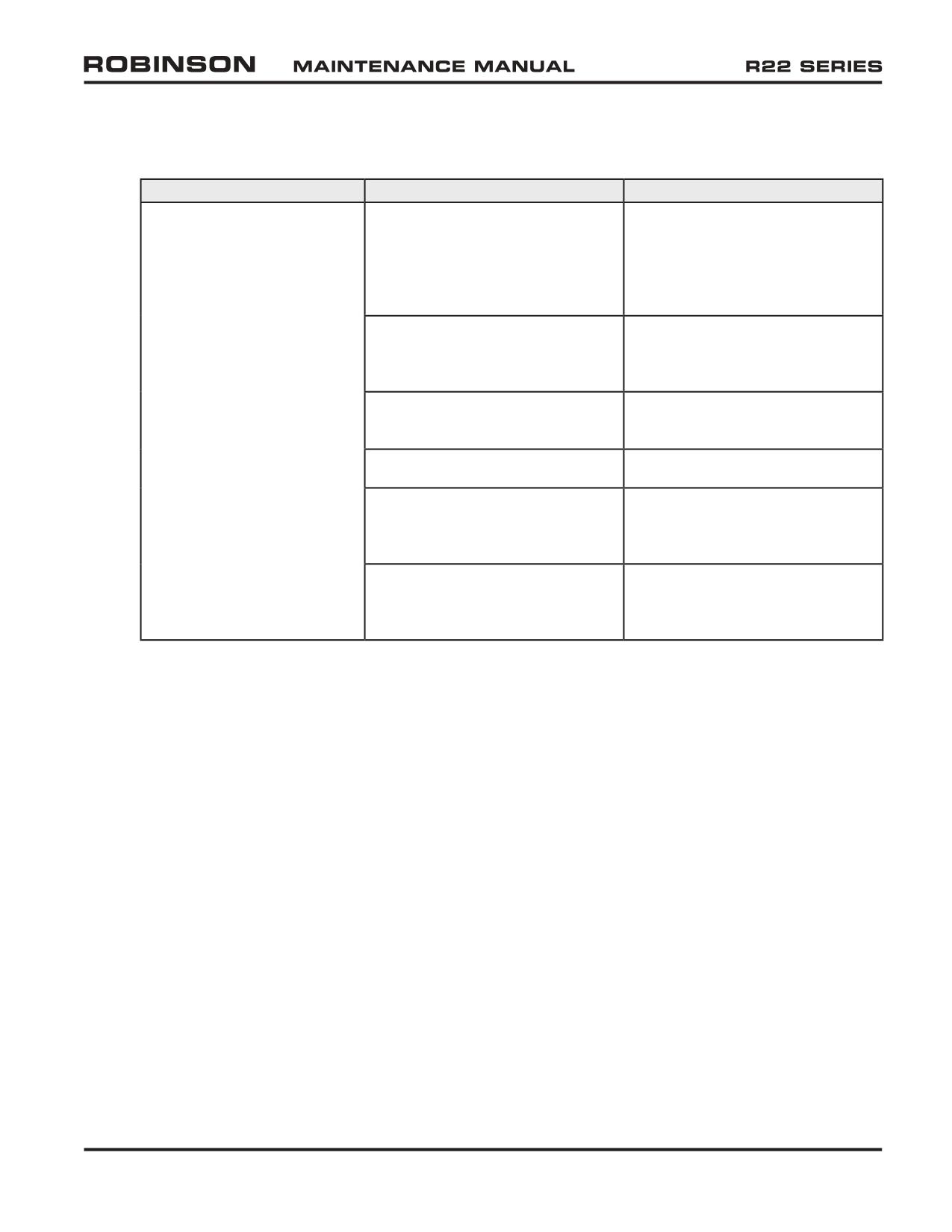
33-110 Troubleshooting (continued)
B. General (continued)
TROUBLE
PROBABLE CAUSE
CORRECTION
Starter kicks back while
Retard breaker contact in engine
Measure retard breaker lead con-
cranking; may cause broken
left magneto pushed out or no
nection. Must be 0.609 in. ±
starter or starter ring gear
connection between lead and
0.10 in. There must be a small
magneto contact
amount of springback which into
magneto.
Incorrect ignition vibrator wiring
Trace ignition vibrator wiring
from ignition switch to magneto.
Correct as required.
Bad ignition switch (See RHC
Replace ignition switch
Service Letter R22 SL-29)
Bad ignition vibrator
Replace vibrator
Incorrect internal magneto re-
Correct as required. Consult
tard breaker timing. Engine left
TCM Aircraft Products literature.
magneto
Impulse coupling starting assist
Replace impulse coupling with
ignition vibrator starting assist.
RHC KI-4.
OCT 2018
Chapter 33 Electrical System
Page 33.15
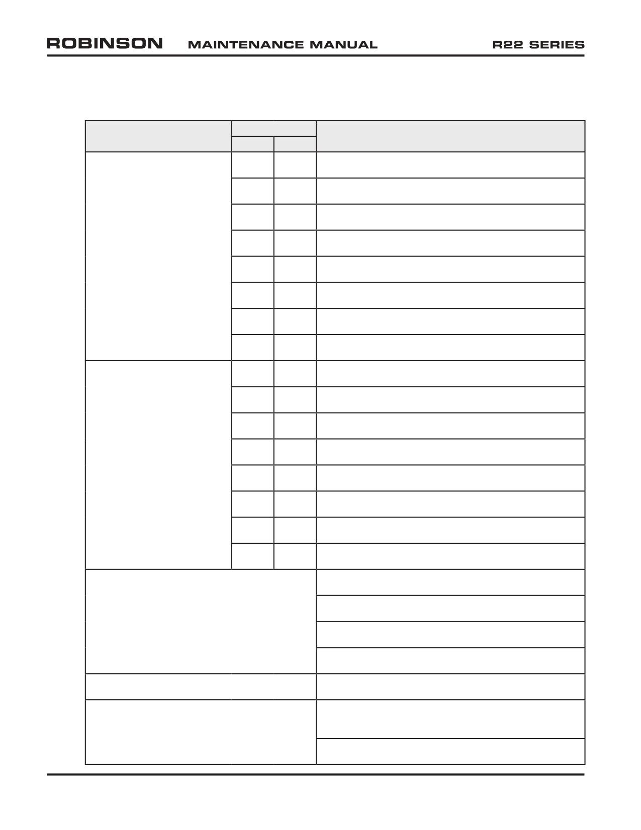
33-110 Troubleshooting (continued)
C. Clutch Actuator Electrical Troubleshooting
CLUTCH LIGHT
TROUBLE
PROBABLE CAUSE
ON
OFF
Disengaged actuator will
X
Motor assembly seized
not engage
X
Motor fuse blown (1½-amp)
X
Open circuit in motor wiring
X
Overtravel switch assembly tripped
X
No voltage at circuit breaker
X
Circuit breaker tripped
X
Spring switch open (normally closed)
X
-88 wire not grounded
Engaged actuator will not
X
Motor assembly seized
disengage
X
Motor fuse blown (1½-amp)
X
Open circuit in motor wiring
X
Overtravel switch assembly tripped
X
No voltage at circuit breaker
X
Circuit breaker tripped
X
Up limit switch stuck (normally closed)
X
-88 wire not grounded
Clutch light flickers in flight
Actuator column spring uncalibrated
A190 drive belts mismatched
Lower drive sheave improperly torqued
A184 or A181 bearing running rough
Clutch light comes on for 1-6 seconds in flight
Normal operation of actuator as it retensions drive belts
Clutch light comes on for more than 6
Drive belts stretched beyond limit of actuator over-
seconds in flight
travel switch. Belts must be replaced.
Actuator overtravel switch activated by outside force
Page 33.16
Chapter 33 Electrical System
OCT 2018
33-110 Troubleshooting (continued)
D. Electrically Powered Instrument Calibration Values
Using Vibrex 2000 balancing equipment (or similar) capable of displaying ± 1 rpm
resolution and calibrated within one year, verify tachometer accuracy per following
tables. Connect equipment in accordance with §§ 10.221 and 6.240 (use photocell
instead of Strobex per Figure 6-4A). Operate aircraft at noted tachometer indications
and verify engine and rotor rpms as specified. Tachometer needles are 1% wide.
A792-x Dual Tachometer
Tachometer indication
Engine RPM
Rotor RPM
97%
2471-2476
494-495
100%
2548-2552
509-510
104%
2649-2655
529-530
The rotor tachometer may be adjusted per § 33-50. No other adjustments are
permitted. If tachometer does not meet accuracy tolerance then it must be replaced
or returned to RHC for repair.
A058-5 Carb. Air Temp. Probe
A604-2 Carb. Air Temp. Gage at 13.7 Vdc;
0° = 89.68/91.08 ohms
77.40 ohms = -30° ± 2°C
15° = 95.67/98.07 ohms
81.73 ohms = -20° ± 1.75°C
16° = 96.10/98.50 ohms
86.05 ohms = -10° ± 1.5°C
17° = 96.54/98.94 ohms
90.38 ohms =
0° ± 1°C
18° = 96.97/99.37 ohms
94.71 ohms =
10° ± 1.5°C
19° = 97.40/99.80 ohms
99.03 ohms =
20° ± 1.75°C
20° = 97.83/100.23 ohms
103.36 ohms =
30° ± 2°C
21° = 98.27/100.67 ohms
22° = 98.70/101.10 ohms
23° = 99.13/101.53 ohms
24° = 99.56/101.96 ohms
25° = 100.00/102.40 ohms
Example: Replacing the carburetor air temperature probe with a ¼ to 1-watt 100-ohm
resistor should result in an indication of approximately 21°C (measure exact resistor
value & refer to above). A probe dipped in a Styrofoam cup full of crushed ice
and water should indicate 90.38 ohms resistance per above table. Probe installation
torque is 3 to 4 inch-pounds; over-torquing probe will result in damage.
OCT 2018
Chapter 33 Electrical System
Page 33.17
33-110 Troubleshooting (continued)
D. Electrically Powered Instrument Calibration Values (continued)
Following instrument cluster gages are calibrated at 20 to 25 degree angle from horizontal.
Fuel level senders should have 90 ± 2 ohms resistance when fully up (full fuel) and 0
to 0.5 ohm when fully down (no fuel). Perform fuel sender calibration per § 12.410
whenever sender is replaced, or if factory-set fuel gage potentiometers have been
disturbed. On backside of each fuel gage are “Null” and “Gain” potentiometer screws,
covered with aluminum tape pressed against the screw heads to prevent rotation.
“Null” potentiometer is adjusted so gage indicates empty at 0.7 ohm sender circuit
resistance; “Gain” potentiometer is adjusted so gage indicates half at 42 ohms sender
circuit resistance. Calibration values are:
Fuel Quantity Gages 6246-00473 (14V)
0.70 ohm = E (empty) -1, +0 pointer width
21.20 ohms =
1/4 full ± 1
pointer width
42.00 ohms =
1/2 full ± 1
pointer width
67.50 ohms =
3/4 full ± 1
pointer width
90.00 ohms =
F (full) ± 1
pointer width
Ammeter 6246-00468 (14V)
-104 mV =
-70 amps ± 1 pointer width
-52 mV =
-35 amps ± 1 pointer width
0 mV =
0 amps ± ¼ pointer width
+52 mV = +35 amps ± 1 pointer width
+ 104 mV = +70 amps ± 1 pointer width
CHT Probe 3080-38 (14V)
CHT Gage 6246-00088 (14V)
200°F = 745 ohms
745 ohms = 200 degrees F ± 1 pointer width
475°F =
38 ohms
110 ohms = 350 degrees F ± 1 pointer width
500°F =
32 ohms
34 ohms = 500 degrees F ±% pointer width
Oil Pressure Sender
115-psi redline Oil Pressure Gage
B308-1 (14V)
6246-00647 (14V)
0 psi =
5-13 ohms
9 ohms =
0 psi ± 1 pointer width
29 psi =
48-57 ohms
46 ohms =
25 psi ± 1 pointer width
58 psi =
84-94 ohms
84 ohms =
55 psi ± 1 pointer width
87 psi = 119-131 ohms
131 ohms =
95 psi ± 1 pointer width
115 psi = 145-161 ohms
152 ohms = 115 psi ± 1 pointer width
Page 33.18
Chapter 33 Electrical System
OCT 2018
33-110 Troubleshooting (continued)
D. Electrically Powered Instrument Calibration Values (continued)
Older, 100-psi red line Oil Pressure Gage
6246-00089 (14V)
0 psi
= 10.0 ohms
25 psi
= 46.5 ohms
60 psi
= 90.0 ohms
90 psi
= 125.5 ohms
100 psi
= 137.0 ohms
Oil Temperature Sender
Oil Temperature Gage
A760-1 (14V)
6246-00090 (14V)
100°F = 497 ohms
903.5 ohms
= 75°F ± 1 pointer width
150°F = 179 ohms
100.0 ohms
= 180°F ± 1 pointer width
200°F = 72 ohms
36.0 ohms
= 245°F ± 1 pointer width
250°F = 34 ohms
OCT 2018
Chapter 33 Electrical System
Page 33.19
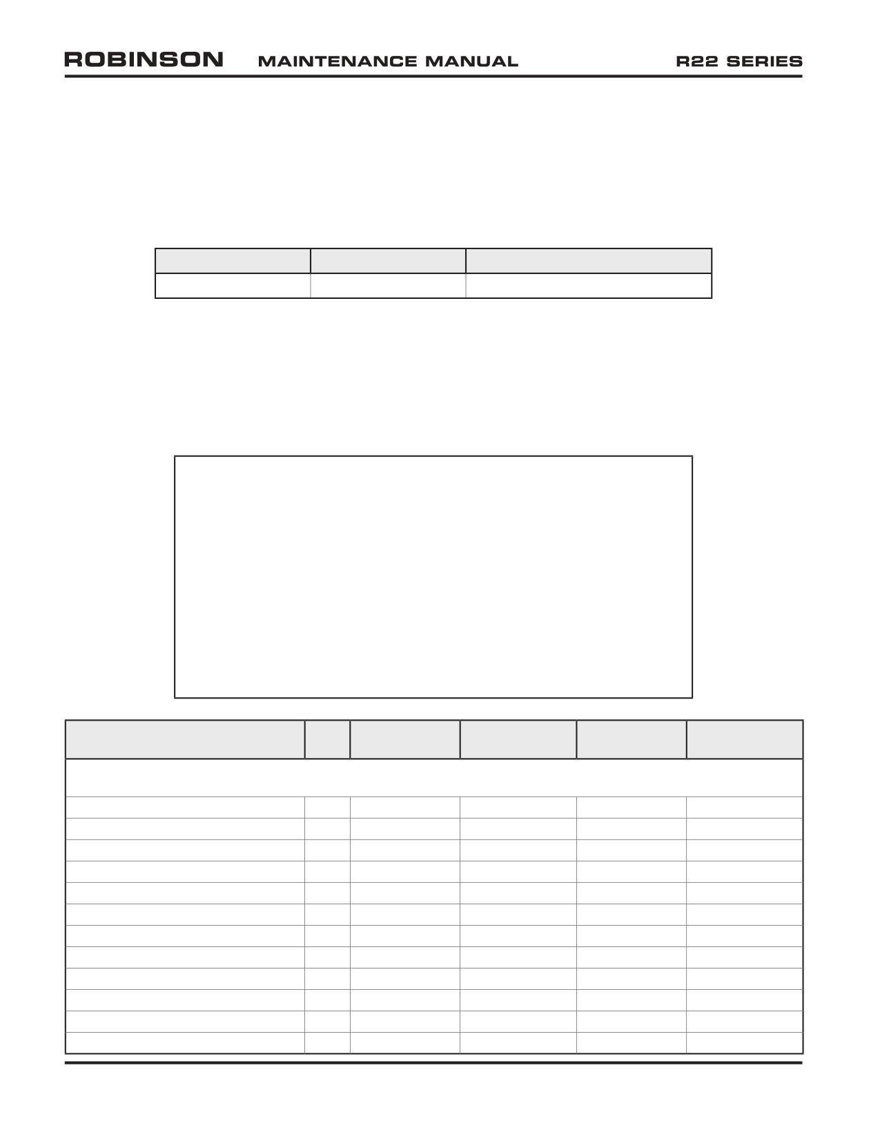
33-120 Electrical Load Analysis
To calculate the total electrical load for a specific helicopter, identify all items of equipment
installed on the helicopter from the table below and sum the corresponding continuous and
intermittent loads.
Maximum continuous alternator load is given in the table below:
System Voltage
Alternator Rating
Maximum Continuous Load
14V
60 amp
54 amps
Intermittent loads are provided for reference.
Alternately, the electrical load may be measured directly at the battery output terminal with
the alternator switched off and all other equipment turned on. The measured load may be
scaled by the ratio of battery voltage to nominal system voltage to obtain a value that is
compared with the alternator load limit.
WARNING
Field (non-factory) installation of electronic equipment can
be hazardous. Due to the compactness of the console and
tunnel containing the controls and wire bundles, installation
of any additional wires can interfere with flight controls.
Electronic tachometers, warning systems, and navigation
equipment essential to flight are sensitive to interference from
other electrical devices. The reliability and accuracy of the
tachometers is essential for safe operation of the helicopter,
and installation of an electrical device not tested and approved
by RHC may result in a hazardous condition.
CONTINUOUS
INTERMITTENT
CONTINUOUS
INTERMITTENT
EQUIPMENT
QTY
AMPS EACH
AMPS EACH
TOTAL
TOTAL
MAIN BUS
ESSEX BATTERY RELAY
1
0.75
0.75
0.75
0.75
KISSLING BATTERY RELAY
1
0.35
0.35
0.35
0.35
ALTERNATOR FIELD
1
2.40
2.40
2.40
2.40
AVIONICS RELAY
1
0.13
0.13
0.13
0.13
ENGINE GAGE CLUSTER
1
0.60
0.60
0.60
0.60
HOURMETER
1
0.03
0.03
0.03
0.03
CARB AIR TEMP
1
0.13
0.13
0.13
0.13
AMMETER
1
0.50
0.50
0.50
0.50
DIGITAL OAT GAGE
1
0.15
0.15
0.15
0.15
MAP LIGHT
1
0.00
0.58
0.00
0.58
WARNING LIGHTS
8
0.00
0.08
0.00
0.64
FULL THROTTLE CAUTION LIGHT
1
0.00
0.08
0.00
0.08
Page 33.20
Chapter 33 Electrical System
OCT 2018
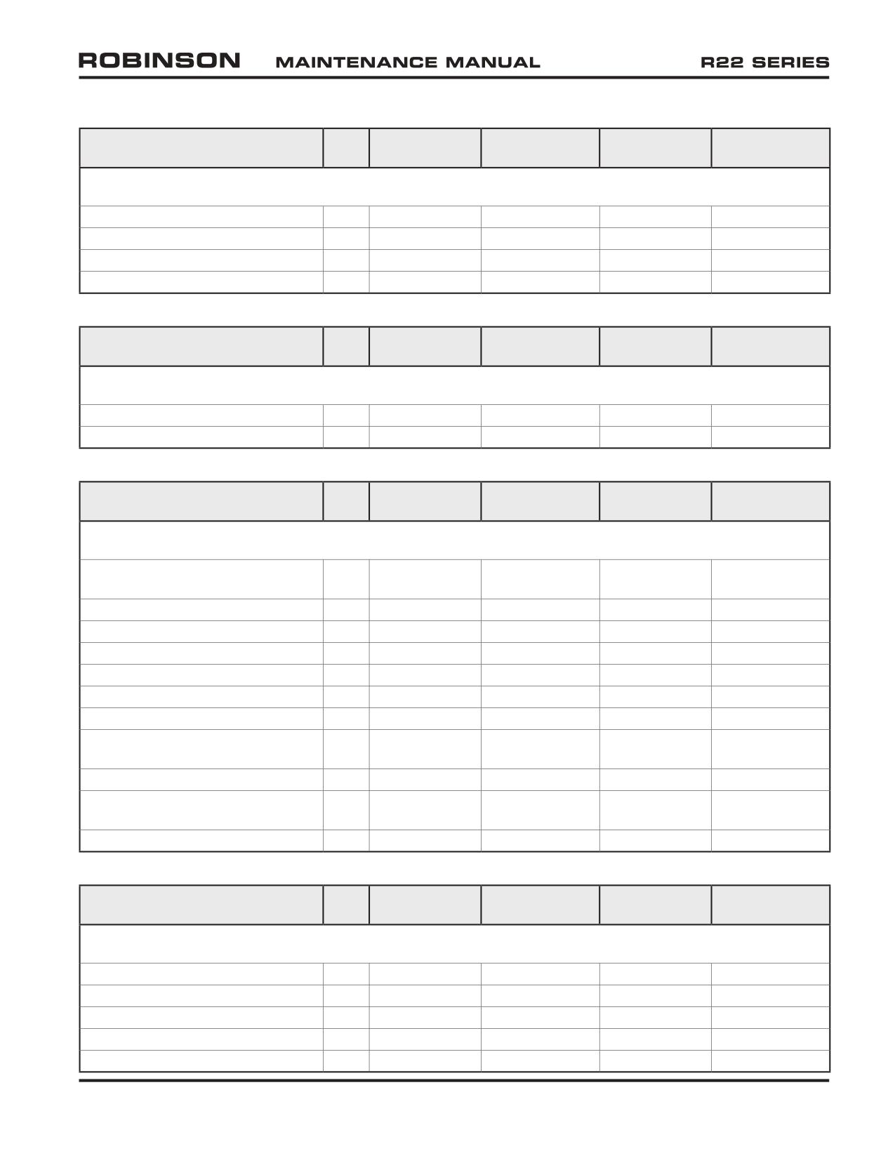
33-120 Electrical Load Analysis (continued)
CONTINUOUS
INTERMITTENT
CONTINUOUS
INTERMITTENT
EQUIPMENT
QTY
AMPS EACH
AMPS EACH
TOTAL
TOTAL
MAIN BUS (continued)
RPM GOVERNOR MOTOR
1
0.00
1.50
0.00
1.50
BELT TENSION ACTUATOR
1
0.00
1.20
0.00
1.20
AUX POWER PLUG (MAX)
1
10.00
10.00
10.00
10.00
HEATER BLOWER
1
7.50
7.50
7.50
7.50
CONTINUOUS
INTERMITTENT
CONTINUOUS
INTERMITTENT
EQUIPMENT
QTY
AMPS EACH
AMPS EACH
TOTAL
TOTAL
TACH BUS
DUAL TACHOMETER (E)
1
0.10
0.10
0.10
0.10
DUAL TACHOMETER (R)
1
0.10
0.10
0.10
0.10
CONTINUOUS
INTERMITTENT
CONTINUOUS
INTERMITTENT
EQUIPMENT
QTY
AMPS EACH
AMPS EACH
TOTAL
TOTAL
LIGHTS BUS
POSITION LIGHTS (L, R, & AFT,
3
2.20
2.20
6.60
6.60
INCANDESCENT)
POSITION LIGHTS (L & R, LED)
2
0.25
0.25
0.50
0.50
POSITION LIGHT (AFT, LED)
1
0.30
0.30
0.30
0.30
OVERHEAD PANEL LIGHT
1
1.00
1.00
1.00
1.00
POST LIGHTS
7
0.08
0.08
0.56
0.56
INSTRUMENT LIGHTS
4
0.20
0.20
0.80
0.80
LANDING LIGHT RELAY
1
0.20
0.20
0.20
0.20
LANDING LIGHTS
2
7.70
7.70
15.40
15.40
(INCANDESCENT)
LANDING LIGHTS (HID)
2
2.90
9.52
5.80
19.04
ANTI-COLLISION LIGHT &
1
3.20
3.20
3.20
3.20
POWER SUPPLY
ANTI-COLLISION LIGHT (LED)
1
0.90
4.00
0.90
4.00
CONTINUOUS
INTERMITTENT
CONTINUOUS
INTERMITTENT
EQUIPMENT
QTY
AMPS EACH
AMPS EACH
TOTAL
TOTAL
AVIONICS
KY197A COM
1
0.80
5.20
0.80
5.20
GTR225B COM
1
0.59
5.31
0.59
5.31
GNS430 COM/NAV/GPS
1
2.44
8.40
2.44
8.40
GTN650 COM/NAV/GPS
1
2.65
6.97
2.65
6.97
KX155 OR KX165 NAV/COM
1
0.70
8.50
0.70
8.50
OCT 2018
Chapter 33 Electrical System
Page 33.21
33-120 Electrical Load Analysis (continued)
CONTINUOUS
INTERMITTENT
CONTINUOUS
INTERMITTENT
EQUIPMENT
QTY
AMPS EACH
AMPS EACH
TOTAL
TOTAL
AVIONICS (continued)
KR87 ADF
1
1.24
1.24
1.24
1.24
KN63 DME
1
1.21
1.21
1.21
1.21
GARMIN TRANSPONDER
1
1.10
3.10
1.10
3.10
GARMIN RADIO NAVIGATION
1
0.41
0.41
0.41
0.41
INDICATOR
KING RADIO NAVIGATION
1
0.08
0.08
0.08
0.08
INDICATOR
MARKER BEACON
1
0.50
0.50
0.50
0.50
KCS55A HSI
1
3.23
3.23
3.23
3.23
RADAR ALTIMETER
1
1.45
1.45
1.45
1.45
AA12S AUDIO CONTROL
1
1.00
1.00
1.00
1.00
GMA 350H AUDIO CONTROL
1
0.80
1.50
0.80
1.50
ASPEN 1000H EFD
1
4.80
4.80
4.80
4.80
ATTITUDE HORIZON
1
0.54
1.40
0.54
1.40
(MECHANICAL)
ATTITUDE HORIZON (LCD)
1
0.20
0.20
0.20
0.20
TURN COORDINATOR
1
0.70
0.70
0.70
0.70
DIRECTIONAL GYRO
1
0.44
1.40
0.44
1.40
PA/SIREN CONTROL
1
0.05
0.05
0.05
0.05
PA/SIREN SPEAKER
1
7.70
7.70
7.70
7.70
ICOM IC-M412 MARINE
1
1.50
5.50
1.50
5.50
TRANSCIEVER
KENWOOD TK-7160 OR TK8160
1
1.00
8.00
1.00
8.00
FM TRANSCIEVER
KENWOOD TK-7180 OR TK8180
1
1.00
9.00
1.00
9.00
FM TRANSCIEVER
YAESU FT-8800R FM
1
0.50
8.00
0.50
8.00
TRANSCIEVER
VERTEX VX-2200 FM
1
2.50
11.00
2.50
11.00
TRANSCIEVER
CONTINUOUS
INTERMITTENT
CONTINUOUS
INTERMITTENT
EQUIPMENT
QTY
AMPS EACH
AMPS EACH
TOTAL
TOTAL
OTHER EQUIPMENT
STARTER RELAY
1
0.00
15.00
0.00
15.00
STARTING VIBRATOR
1
0.00
2.50
0.00
2.50
STARTER MOTOR
1
0.00
200.00
0.00
200.00
CLOCK, STANDARD
1
0.02
0.02
0.02
0.02
CLOCK, DIGITAL
1
0.00
0.00
0.00
0.00
Page 33.22
Chapter 33 Electrical System
OCT 2018
CHAPTER 34
AVIONICS
Section Title
Page
34-10
Avionics Switch Description
34.1
34-20
Transponder Installations
34.1
34-21
A804-12 Transponder (Garmin GTX 330 ES) Installation
34.1
34-30
COM Radio Installations
34.4
34-31
C802-2 COM Radio (Garmin GTR 225B) Installation
34.4
34-40
Audio Control Installations
34.6
34-41
C822-1 Audio Control (Garmin GMA 350H) Installation
34.6
34-50
GPS Installations
34.8
34-51
C831 GPS (Garmin GTN 600 series) Installation
34.8
34-60
Avionics Software
34.10
OCT 2018
Chapter 34 Avionics
Page 34.i
Intentionally Blank
Page 34.ii
Chapter 34 Avionics
OCT 2018
CHAPTER 34
AVIONICS
34-10 Avionics Switch Description
R22 Helicopters S/N 4591, 4650, 4651, 4656 & subsequent have a dedicated avionics
switch located on the main switch panel on top of the avionics stack. Earlier R22s have an
avionics bus, but the master radio relay interrupts power to the avionics bus during start-
up, eliminating the need for a switch. The avionics switch controls a relay which interrupts
power to the avionics bus (system is fail-safe ON).
34-20 Transponder Installations
34-21 A804-12 Transponder (Garmin GTX 330 ES) Installation
NOTE
Refer to Garmin GTX
330 ES Maintenance Manual and
Instructions for Continued Airworthiness.
A. Description
Automatic Dependent Surveillance-Broadcast (ADS-B) “Out” equipment transmits aircraft
specific-data and position information to air traffic control via GPS-based surveillance
(rather than radar-based surveillance). ADS-B Out equipment will be required for R22
operation in certain airspace in the United States after January 1, 2020.
ADS-B Out system operates mostly automatically. ADS-B Out equipment is
programmed with aircraft-specific data at installation. ADS-B Out system uses
the primary installed GPS for position information. Additional flight-specific data is
entered by the pilot using transponder controls. ADS-B data is transmitted via the
transponder’s Extended Squitter (ES) on frequency 1090 MHz.
ADS-B Out equipment (transponder and primary GPS) must have power and must
be in normal operating modes for systems to function properly. ADS-B Out system
faults are annunciated on the transponder and primary GPS screens.
Change of aircraft registration may require ADS-B equipment programming by
qualified maintenance personnel.
Refer to R22 Pilot’s Operating Handbook Section 9 for additional information.
B. Schematic
Refer to Figure 14-41 for A804-12 transponder & blind encoder electrical schematic.
OCT 2018
Chapter 34 Avionics
Page 34.1
34-21 A804-12 Transponder (Garmin GTX 330 ES) Installation (continued)
C. Removal
1. Turn battery switch off and pull out XPDR circuit breaker (5 amp) at panel.
2. Loosen radio key securing A804-12 transponder to avionics tray.
3. Carefully unplug/remove transponder from tray.
D. Installation
1. Turn battery switch off and pull out XPDR circuit breaker (5 amp) at panel.
2. Carefully plug-in/install A804-12 transponder in appropriate location in avionics
tray.
3. Tighten radio key securing transponder to tray. Verify equipment security.
4. Push in XPDR circuit breaker (5 amp) at panel. Turn battery & avionics switches
on.
5. Perform appropriate functional checks per Garmin GTX 330 ES Pilot's Guide.
Turn battery and avionics switches off.
E. Antenna
Refer to § 16-70 for antenna locations and R22 Illustrated Parts Catalog (IPC) Chapter
6.
NOTE
Antenna installation depends on optional equipment installed.
Removal
1. Turn battery switch off and pull out XPDR circuit breaker (5 amp) at panel.
2. Using plastic scraper, remove B270-1 sealant from around transponder antenna
at corners where it attaches to A794-2 panel.
3. Remove screws securing panel to cabin skin and disconnect antenna cable
from antenna. Remove hardware securing antenna and ground wire to panel
and remove antenna.
Page 34.2
Chapter 34 Avionics
OCT 2018
34-21 A804-12 Transponder (Garmin GTX 330 ES) Installation (continued)
E. Antenna (continued)
Installation
1. Turn battery switch off and pull out XPDR circuit breaker (5 amp) at panel.
2. Remove paint and primer from A794-2 panel where ground wire attaches to
ensure electrical ground.
3. Install hardware securing transponder antenna and ground wire to panel. Verify
security. Connect antenna cable to antenna and install screws securing panel
to cabin skin. Verify security.
4. Apply small bead B270-1 sealant (0.1 inch max in height) around antenna at
corners where it attaches to panel and allow to dry.
5. Perform ground checks per Part D steps 4 and 5.
F. Scheduled Maintenance and Inspections
NOTE
All factory-installed Garmin units are “on condition” and do not
require scheduled periodic maintenance. Units feature a BIT
(Built-In Test) function during each initial power-up that will
detect internal failure(s) and alert pilot.
NOTE
Refer to § 34-60 for avionics software information.
G. Special Maintenance and Inspections
1. Turn battery and avionics switches off. Open circuit breaker panel and upper
console.
2. Inspect condition of and verify no obvious damage to transponder, radio tray,
copper bus bars, circuit breaker, and wiring. Verify no loose, chafed, or broken
wires or terminals. Verify no evidence of arcing. Verify equipment security.
3. Secure circuit breaker panel and upper console. Perform ground checks per Part
D steps 4 and 5.
OCT 2018
Chapter 34 Avionics
Page 34.3
34-30 COM Radio Installations
34-31 C802-2 COM Radio (Garmin GTR 225B) Installation
A. Description
The C802-2 COM radio (Garmin GTR 225B) includes similar communication features
available in the earlier King KY197A COM radio, but includes an airport frequency
database, ability to monitor the standby frequency, and improved user memory
channel functionality. The Garmin GTR 225B is a dual voltage unit, suitable for use
in 14V and 28V systems.
B. Schematic
Refer to Figure 14-43 for C802-2 COM Radio Installation electrical schematic.
C. Removal
1. Turn battery switch off and pull-out COM radio circuit breaker (10 amp) at panel.
2. Loosen radio key securing C802-2 COM radio to avionics tray.
3. Carefully unplug/remove radio from tray.
D. Installation
1. Turn battery switch off and pull-out COM radio circuit breaker (10 amp) at panel.
2. Carefully plug-in/install C802-2 COM radio in appropriate location in avionics
tray.
3. Tighten radio key securing radio to tray. Verify equipment security.
4. Push-in COM radio circuit breaker (10 amp) at panel. Turn battery and avionics
switches on.
5. Perform appropriate functional checks per Garmin GTR 225B Pilot's Guide. Turn
battery and avionics switches off.
E. Antenna
Refer to § 16-70 for antenna locations and R22 Illustrated Parts Catalog (IPC) Chapter
6.
NOTE
Antenna installation depends on number of COM installations
and additional equipment installed.
Page 34.4
Chapter 34 Avionics
OCT 2018
34-31 C802-2 COM Radio (Garmin GTR 225B) Installation (continued)
E. Antenna (continued)
Removal
1. Turn battery switch off and pull out COM radio circuit breaker (10 amp) at panel.
2. Using plastic scraper, remove B270-1 sealant from around COM antenna at
corners where it attaches to tailcone.
3. Disconnect antenna cable from antenna. As required, remove B270-13 sealant from
fastener holes. Remove screws securing antenna to tailcone and remove antenna.
Installation
1. Turn battery switch off and pull out COM radio circuit breaker (10 amp) at panel.
2. Remove paint & primer from antenna mating surfaces to ensure electrical ground.
3. As required, apply light coat B270-13 sealant to screw threads and install
screws securing antenna to tailcone. As required, seal around screw heads and
fill fastener holes using B270-13 sealant and allow to dry. Verify security.
4. Apply small bead B270-1 sealant (0.1 inch max in height) around antenna at
corners where it attaches to tailcone and allow to dry.
5. Connect antenna cable to antenna. Verify security.
6. Perform ground checks per Part D steps 4 and 5.
F. Scheduled Maintenance and Inspections
NOTE
All factory-installed Garmin units are “on condition” and do not
require scheduled periodic maintenance. Units feature a BIT
(Built-In Test) function during each initial power-up that will
detect internal failure(s) and alert pilot.
NOTE
Refer to § 34-60 for avionics software information.
G. Special Maintenance and Inspections
1. Turn battery and avionics switches off. Open circuit breaker panel and upper console.
2. Inspect condition of and verify no obvious damage to COM radio, radio tray,
copper bus bars, circuit breaker, and wiring. Verify no loose, chafed, or broken
wires or terminals. Verify no evidence of arcing. Verify equipment security.
3. Secure circuit breaker panel and upper console. Perform ground checks per Part
D steps 4 and 5.
OCT 2018
Chapter 34 Avionics
Page 34.5
34-40 Audio Control Installations
34-41 C822-1 Audio Control (Garmin GMA 350H) Installation
NOTE
Refer to Garmin GMA 350H series Maintenance Manual and
Instructions for Continued Airworthiness.
A. Description
The Garmin GMA 350H audio control includes improved squelch and background
noise suppression, 3D audio (if stereo headsets are used) which allows inputs from
separate radios to sound as if they are coming from separate locations around the
listener, and some control functions via voice command when a momentary push-
button switch is depressed on the pilot's cyclic grip.
B. Schematic
Refer to Figure 14-44 for C822-1 Audio Control Installation electrical schematic.
C. Removal
1. Turn battery switch off and pull out AUDIO PANEL circuit breaker (5 amp) at
panel.
2. Loosen radio key securing Garmin GMA 350H audio control to avionics tray.
3. Carefully unplug/remove audio control from tray.
D. Installation
1. Turn battery switch off and pull out AUDIO PANEL circuit breaker (5 amp) at
panel.
2. Carefully plug-in/install Garmin GMA 350H audio control in appropriate location
in avionics tray.
3. Tighten radio key securing audio control to tray. Verify equipment security.
4. Push in AUDIO PANEL circuit breaker (5 amp) at panel. Turn battery & avionics
switches on.
5. Perform appropriate functional checks per Garmin GMA 350H series Pilot's Guide.
Turn battery & avionics switches off.
E. Antenna
Refer to § 16-70 for antenna locations and R22 Illustrated Parts Catalog (IPC) Chapter
6.
Page 34.6
Chapter 34 Avionics
OCT 2018
34-41 C822-1 Audio Control (Garmin GMA 350H) Installation (continued)
E. Antenna (continued)
Removal
1. Turn battery switch off & pull out AUDIO PANEL circuit breaker (5 amp) at panel.
2. Using plastic scraper, remove B270-1 sealant from around CI 102 marker
beacon antenna at corners where it attaches to A794-2 panel.
3. Remove hardware securing panel to belly and disconnect A850-210 antenna cable
from antenna. Carefully remove screws (they are installed with threadlocker)
securing antenna to panel and remove antenna.
Installation
1. Turn battery switch off & pull out AUDIO PANEL circuit breaker (5 amp) at panel.
2. Remove paint & primer from antenna mating surfaces to ensure electrical ground.
3. Apply light coat B270-11 adhesive to new screw threads and install screws
securing CI 102 marker beacon antenna to A794-2 panel. Verify security.
4. Connect A850-210 antenna cable to antenna. Install screws securing forward
belly panel to belly. Verify security.
5. Apply small bead B270-1 sealant (0.1 inch max in height) around antenna at
corners where it attaches to belly panel and allow to dry.
6. Perform ground checks per Part D steps 4 and 5.
F. Scheduled Maintenance and Inspections
NOTE
All factory-installed Garmin units are “on condition” and do not
require scheduled periodic maintenance. Units feature a BIT
(Built-In Test) function during each initial power-up that will
detect internal failure(s) and alert pilot.
NOTE
Refer to § 34-60 for avionics software information.
G. Special Maintenance and Inspections
1. Turn battery & avionics switches off. Open circuit breaker panel and upper console.
2. Inspect condition of and verify no obvious damage to audio control, radio tray,
copper bus bars, circuit breaker, and wiring. Verify no loose, chafed, or broken
wires or terminals. Verify no evidence of arcing. Verify equipment security.
3. Secure circuit breaker panel and upper console. Perform ground checks per Part
D steps 4 and 5.
OCT 2018
Chapter 34 Avionics
Page 34.7
34-50 GPS Installations
34-51 C831 GPS (Garmin GTN 600 series) Installation
NOTE
Refer to Garmin GTN 600 series Maintenance Manual and
Instructions for Continued Airworthiness.
A. Description
The C831 GPS (Garmin GTN 600 series) includes similar navigation features available
in the earlier Garmin GNS 400 series GPS, but the interface offers a combination of
touch screen technology with traditional buttons and knobs.
One GTN 600 series GPS may be installed in the pilot-side console location only.
Note: R22 ADS-B Out system requires Garmin GTN 600-series GPS. Refer to §
14.1230.
B. Schematic
Refer to Figure 14-45 for C831 GPS (Garmin GTN 600 series) installation electrical
schematic.
C. Removal
1. Turn battery switch off and pull out COM circuit breakers(s) (10 amp) and GPS
circuit breaker(s) (7.5 amp) as required at panel.
2. Loosen radio key securing C831 GPS to tray in pilot's side console.
3. Carefully unplug/remove GPS from tray.
D. Installation
1. Turn battery switch off and pull out COM circuit breakers(s) (10 amp) and GPS
circuit breaker(s) (7.5 amp) as required at panel.
2. Carefully plug-in/install C831 GPS in tray in pilot's side console.
3. Tighten radio key securing GPS to tray. Verify equipment security.
4. Push in COM circuit breaker(s) (10 amp) and GPS circuit breaker(s) (7.5 amp) as
required at panel. Turn battery and avionics switches on.
5. Perform appropriate functional checks per Garmin GTN 600 series Pilot's Guide.
Turn battery and avionics switches off.
Page 34.8
Chapter 34 Avionics
OCT 2018
34-51 C831 GPS (Garmin GTN 600 series) Installation (continued)
E. Antenna
Refer to § 16-70 for antenna locations and R22 Illustrated Parts Catalog (IPC) Chapter 6.
NOTE
Antenna installation depends on number COM installations and
additional equipment installed.
Removal
1. Turn battery switch off and pull out COM circuit breaker(s) (10 amp) and GPS
circuit breaker(s) (7.5 amp) as required at panel.
2. Using plastic scraper, remove B270-1 sealant from around GPS antenna at
corners where it attaches to tailcone.
3. Disconnect antenna cable from antenna. As required, remove B270-13 sealant
from fastener holes. Remove screws securing antenna to tailcone and remove
antenna.
Installation
1. Turn battery switch off and pull out COM circuit breaker(s) (10 amp) and GPS
circuit breaker(s) (7.5 amp) as required at panel.
2. Remove paint & primer from antenna mating surfaces to ensure electrical ground.
3. As required, apply light coat B270-13 sealant to screw threads and install
screws securing antenna to tailcone. As required, seal around screw heads
and fill fastener holes using B270-13 sealant and allow to dry. Verify security.
4. Apply small bead B270-1 sealant (0.1 inch max in height) around antenna at
corners where it attaches to tailcone and allow to dry.
5. Connect antenna cable to antenna. Verify security.
6. Perform ground checks per Part D steps 4 and 5.
F. Scheduled Maintenance and Inspections
NOTE
All factory-installed Garmin units are “on condition” and do not
require scheduled periodic maintenance. Units feature a BIT
(Built-In Test) function during each initial power-up that will
detect internal failure(s) and alert pilot.
NOTE
Refer to § 34-60 for avionics software information.
OCT 2018
Chapter 34 Avionics
Page 34.9
34-51 C831 GPS (Garmin GTN 600 series) Installation (continued)
G. Special Maintenance and Inspections
1. Turn battery and avionics switches off. Open circuit breaker panel. Remove
hardware securing pilot's side console shell assembly to tray and carefully pivot
shell assembly upward (GPS and faceplate may be also be removed).
2. Inspect condition of and verify no obvious damage to GPS, tray, copper bus bars,
circuit breaker, and wiring. Verify no loose, chafed, or broken wires or terminals.
Verify no evidence of arcing. Verify equipment security.
3. Secure circuit breaker panel and pilot's side console. Perform ground checks per
Part D steps 4 and 5.
34-60 Avionics Software
Modern avionics software is complex and subject to rigorous testing by RHC to assure proper
function and integration in the aircraft. Only specified software versions and software
configurations have been FAA-approved for installation in Robinson helicopters. Software
updates should not be attempted without a thorough understanding of approval status and
compatibility. Technical support from either RHC or the avionics manufacturer will likely be
required. In some cases, updating software for one item of avionics may require additional
avionics to be updated to assure compatibility.
As long as RHC-installed equipment is functioning properly, there is no continuing
airworthiness requirement to check or update software levels in Robinson helicopters; RHC
will issue an SB (or FAA will issue an AD) for any mandatory updates.
Software page for approved software configurations.
NOTE
The above statements apply to avionics operating software.
Databases (e.g. charts, terrain, etc.) may be updated regularly
using avionics manufacturer’s recommended procedures.
Page 34.10
Chapter 34 Avionics
OCT 2018
CHAPTER 35
WIRING DIAGRAMS
Section Title
Page
35-00
Description
35.1
OCT 2018
Chapter 35 Wiring Diagrams
Page 35.i
Intentionally Blank
Page 35.ii
Chapter 35 Wiring Diagrams
OCT 2018
CHAPTER 35
WIRING DIAGRAMS
35-00 Description
Reserved.
OCT 2018
Chapter 35 Wiring Diagrams
Page 35.1
Intentionally Blank
Page 35.2
Chapter 35 Wiring Diagrams
OCT 2018
CHAPTER 36
SPECIAL TOOLS
Section Title
Page
36-10
Special Tools
36.1
36-20
Illustrations and Tasks
36.2
OCT 2018
Chapter 36 Special Tools
Page 36.i
Intentionally Blank
Page 36.ii
Chapter 36 Special Tools
OCT 2018
CHAPTER 36
SPECIAL TOOLS
36-10 Special Tools
The following is a list of Robinson R22-series special tools.
R22-series special tools are to be used in conjunction with the applicable instructions for
continued airworthiness, for their designated maintenance task.
OCT 2018
Chapter 36 Special Tools
Page 36.1
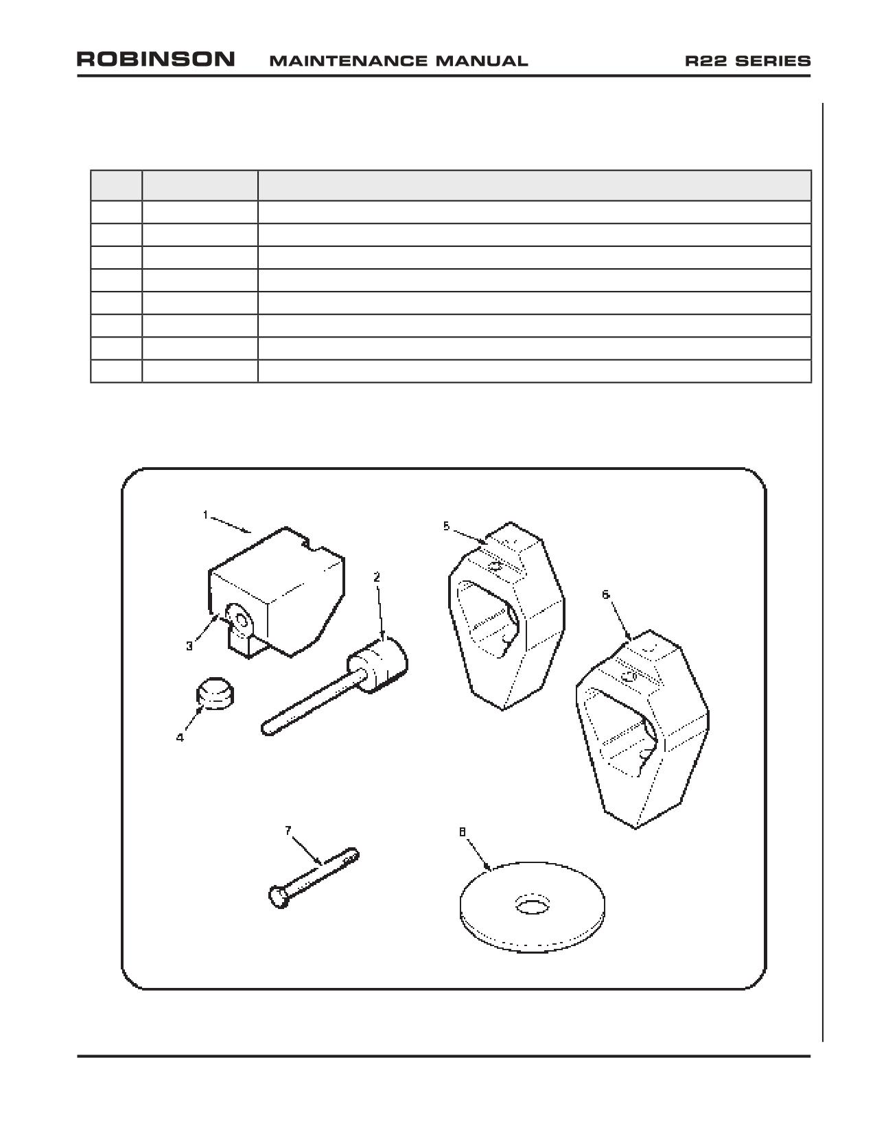
36-20 Illustrations and Tasks
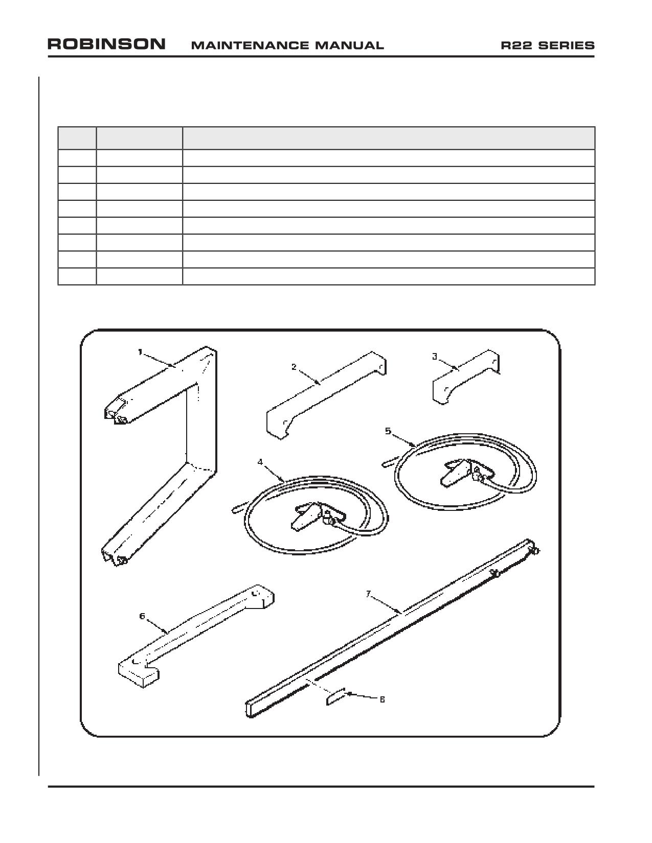
Refer to Figure 36-1.
Item
Part Number
Description
1
MT016-1
Engine Hoist
2
MT050-1
Main Rotor Rigging Fixture
3
MT050-2
Tail Rotor Rigging Fixture
4
MT053-1
Main Gearbox Drain Assembly - Thread Type Chip Detector
5
MT054-1
Main Gearbox Drain Assembly - Quick Disconnect Chip Detector
6
MT068-1
Horizontal Stabilizer Rigging Tool
7
MT091-1
Holder - Engine Ring Gear (includes MT091-3 decal)
8
MT091-3
Decal (torquing instructions)
FIGURE 36-1 SPECIAL TOOLS
Page 36.2
Chapter 36 Special Tools
OCT 2018
36-20 Illustrations and Tasks (continued)
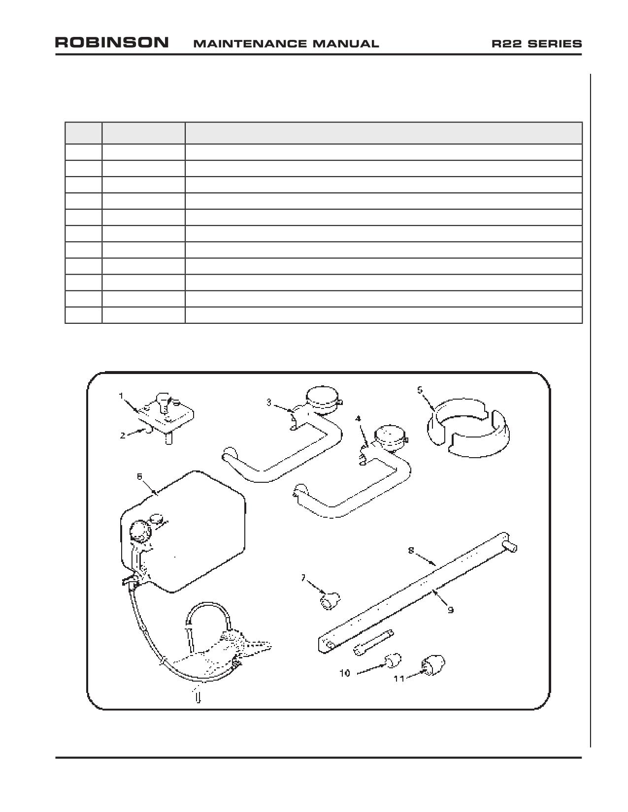
Refer to Figure 36-2.
Item
Part Number
Description
1
MT092-1
Fan Puller (includes MT092-3 spacer)
2
MT092-3
Spacer - Fan Puller
3
MT122-1
Main Rotor Hub, Bolt Elongation (teeter hinges & A154-1 hub coning hinges)
4
MT122-15
Main Rotor Hub, Bolt Elongation (B370-1 hub coning hinges)
5
MT146-1
Blocks - Swashplate Rigging (set of 2)
6
MT147-1
Bleed Tool - Main Rotor Blade Spindle
7
MT173-4
Socket - 1-11/16 (3/4-inch drive, 12-point)
8
MT173-5
Torque Wrench Extension - Tool Set (no longer available)
9
MT173-6
Tube Weldment (no longer available)
10
MT173-7
Socket - 1-1/2-inch (3/4-inch drive, 12-point)
11
MT173-8
Socket - 2-inch (3/4-inch drive, 12-point)
FIGURE 36-2 SPECIAL TOOLS
OCT 2018
Chapter 36 Special Tools
Page 36.3
36-20 Illustrations and Tasks (continued)
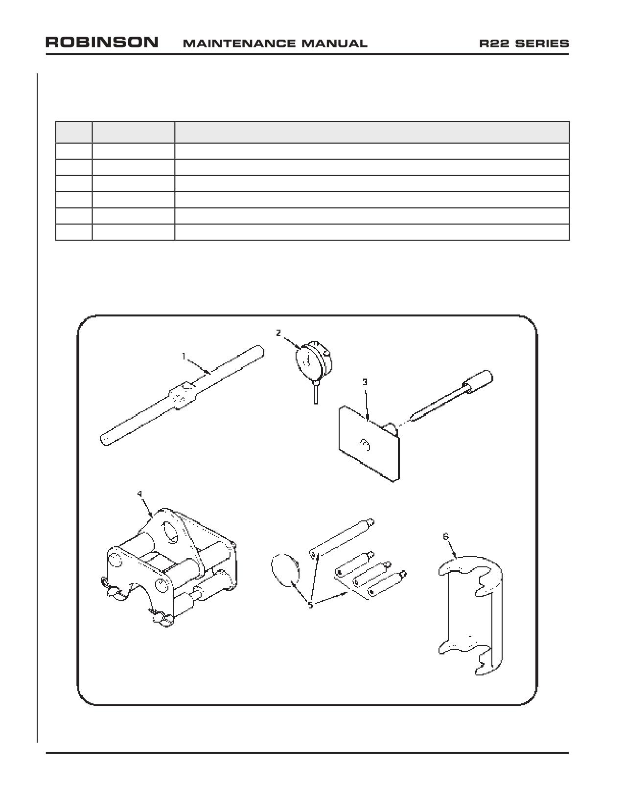
Refer to Figure 36-3.
Item
Part Number
Description
1
MT179-4
Balancing Bar - Tail Rotor Assembly Static Balance
2
MT200-1
Dial Indicator
3
MT201-1
Pressing Fixture - Tail Rotor Hub Bearing
4
MT234-1
Helicopter Lifting Fixture
5
MT260-6
Tail Rotor Drive Shaft Runout Attachments Kit
6
MT294-1
Collective Spring Retainer
FIGURE 36-3 SPECIAL TOOLS
Page 36.4
Chapter 36 Special Tools
OCT 2018
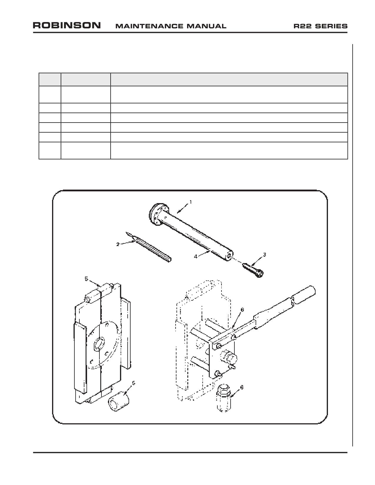
36-20 Illustrations and Tasks (continued)
Refer to Figure 36-4.
Item
Part Number
Description
1
MT295-1
Tail Rotor Gearbox Output Shaft Seal Replacement Tools (includes items 2, 3, 4,
and Figure 36-9 item 5)
2
MT295-3
Punch
3
MT295-6
Screw
4
MT295-10
Mandrel
5
MT303-1
Clutch Bearing (A184) Removal and Installation Tools
6
MT303-3
Clutch Bearing (A184) Removal and Installation Tools (use with MT303-1 tools
when hydraulic press is unavailable)
FIGURE 36-4 SPECIAL TOOLS
OCT 2018
Chapter 36 Special Tools
Page 36.5
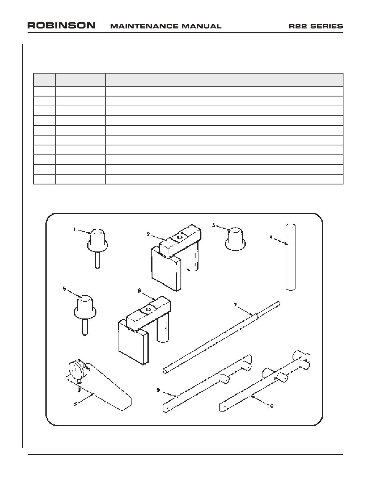
36-20 Illustrations and Tasks (continued)
Refer to Figure 36-5.
Item
Part Number
Description
1
MT329-1
Plug Assembly (A648-1 or A648-3 Bearings)
2
MT329-2
Support Weldment (A154-1 Hub)
3
MT329-8
Plug - Main Rotor Hub Bearing Installation
4
MT329-10
Tube
5
MT329-11
Plug Assembly (A648-2 Bearings)
6
MT329-13
Support Weldment
7
MT331-4
Sheave Alignment Bar
8
MT352-1
Main Rotor Blade Trim Tab Gage (includes MT200-1 dial indicator)
9
MT354-1
Teeter Moment Tool (no longer available; replaced by MT354-7)
10
MT354-7
Teeter Moment Tool (R22, R44, R66)
FIGURE 36-5 SPECIAL TOOLS
Page 36.6
Chapter 36 Special Tools
OCT 2018
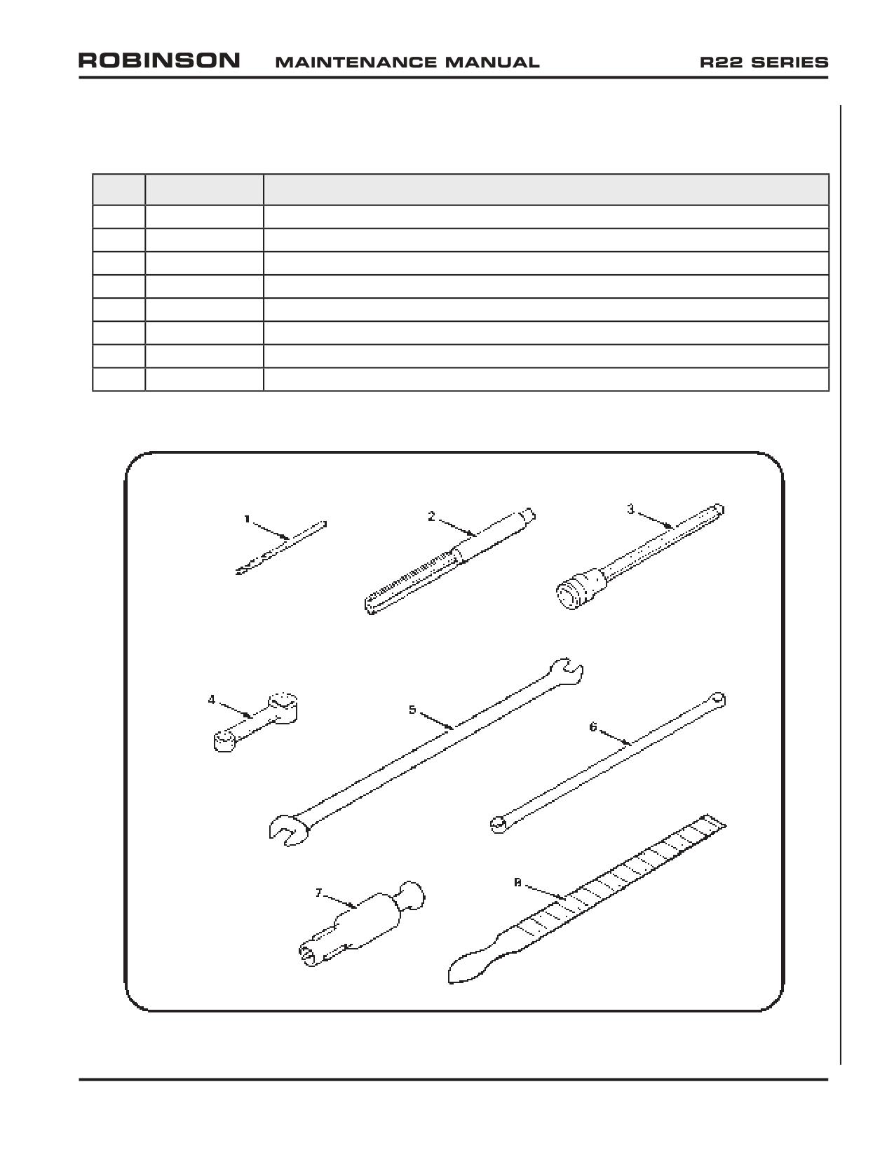
36-20 Illustrations and Tasks (continued)
Refer to Figure 36-6.
Item
Part Number
Description
1
MT357-1
0.125-inch dia. Cobalt Drill Bit
2
MT357-2
0.375-inch diameter Reamer
3
MT357-4
Hex Driver (Snap-On Part No. FABL8)
4
MT357-5
Torque Adapter (Snap-On Part No. FRDH101)
5
MT357-6
Wrench (Open end; Snap-On Part No. LTA1214)
6
MT357-7
Wrench (Box end; Snap-On Part No. XDH78A)
7
MT357-8
Nipple Chuck
8
MT357-9
Taper Gage
FIGURE 36-6 SPECIAL TOOLS
OCT 2018
Chapter 36 Special Tools
Page 36.7
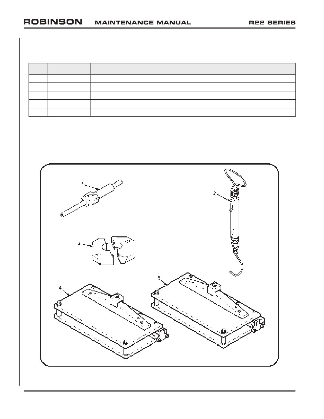
36-20 Illustrations and Tasks (continued)
Refer to Figure 36-7.
Item
Part Number
Description
1
MT358-1
0.750-inch dia. Spot-Facing Tool
2
MT359-1
Spring Scale (0-30 lb)
3
MT376-1
Blocks - Main Rotor Rigging (set; holds cyclic in neutral position)
4
MT526-1
Main Rotor Blade Trim Tab Bender (stainless steel skin)
5
MT526-8
Main Rotor Blade Trim Tab Bender (aluminum skin)
FIGURE 36-7 SPECIAL TOOLS
Page 36.8
Chapter 36 Special Tools
OCT 2018
36-20 Illustrations and Tasks (continued)
Refer to Figure 36-8.
Item
Part Number
Description
1
MT556-1
Tail Rotor Elastomeric Bearing Replacement Tools (includes items 2 thru 4, and 7)
2
MT556-2
Mandrel Assembly
3
MT556-5
Support
4
MT556-6
Cap
5
MT569-1
Main Rotor Bolt Drilling Fixture (teeter hinge & A154-1 hub coning hinge bolts)
6
MT569-6
Main Rotor Bolt Drilling Fixture (B370-1 hub coning hinge bolts)
7
AN4-25A
Bolt
8
AN970-4*
Washer - Tap Test Tool
* Or 1965 or later U.S. quarter dollar coin in good condition.
FIGURE 36-8 SPECIAL TOOLS
OCT 2018
Chapter 36 Special Tools
Page 36.9
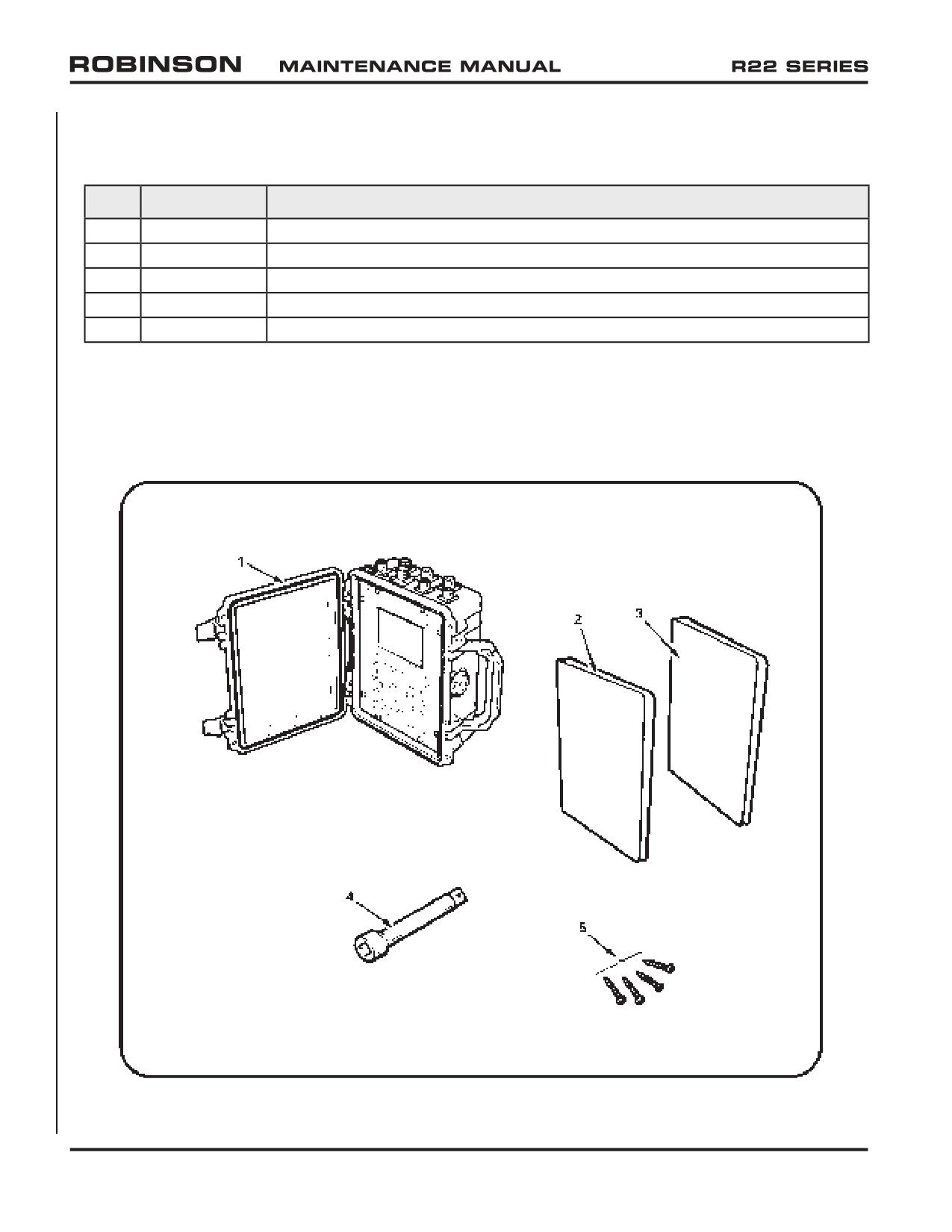
36-20 Illustrations and Tasks (continued)
Refer to Figure 36-9.
Item
Part Number
Description
1
2020HR
ACES Probalancer Analyzer (or equivalent dynamic balancer)
2
60297-12
Engine Operator’s Manual (O-360 engine; refer to Lycoming Service Letter No. L114)
3
60297-30
Engine Operator’s Manual (O-320 engine; refer to Lycoming Service Letter No. L114)
4
9HT4441
Extension Bar (3/4 square drive x 8 inch)
5
92470A113
Screws (#4 x 0.75 inch)
FIGURE 36-9 SPECIAL TOOLS
Page 36.10
Chapter 36 Special Tools
OCT 2018
CHAPTER 37
REVISION LOG
Section
Title
Page
37-00
Revision Log
37.1
OCT 2018
Chapter 37 Revision Log
Page 37.i
Intentionally Blank
Page 37.ii
Chapter 37 Revision Log
OCT 2018
REVISION LOG
OCT 2018
The R22 Maintenance Manual (MM) list of effective pages and effective dates are given
below. If a previously issued page is not listed below, it is no longer an effective page and
must be discarded. The issue or revision date is in bold at the top of each revision log page.
revision date is current. A subscription service form is included in the front of this manual.
Page
Date
Page
Date
Page
Date
i
OCT 2018
2.3
OCT 2018
2.35
OCT 2018
ii
OCT 2018
2.4
OCT 2018
2.36
OCT 2018
iii
OCT 2018
2.5
OCT 2018
2.37
OCT 2018
iv
OCT 2018
2.6
OCT 2018
2.38
OCT 2018
v
OCT 2018
2.7
OCT 2018
2.39
OCT 2018
vi
OCT 2018
2.8
OCT 2018
2.40
OCT 2018
2.9
APR 2007
2.41
OCT 2018
1.i
OCT 2018
2.10
JUN 2006
2.42
OCT 2018
1.ii
OCT 2018
2.11
JUN 2006
2.43
JUN 2006
1.1
OCT 2018
2.12
JUN 2006
2.44
JUN 2006
1.2
OCT 2018
2.13
OCT 2018
2.45
JUN 2006
1.3
OCT 2018
2.14
OCT 2018
2.46
APR 2007
1.4
OCT 2018
2.15
JUN 2006
2.47
JUN 2006
1.5
OCT 2018
2.16
JUN 2006
2.48
JUN 2006
1.6
OCT 2018
2.17
OCT 2018
2.49
JUN 2006
1.7
OCT 2018
2.18
OCT 2018
2.50
APR 2007
1.8
OCT 2018
2.19
OCT 2018
2.51
JUN 2006
1.9
OCT 2018
2.20
OCT 2018
2.52
JUN 2006
1.10
OCT 2018
2.21
OCT 2018
2.53
JUN 2006
1.11
OCT 2018
2.22
OCT 2018
2.54
JUN 2006
1.12
OCT 2018
2.23
OCT 2018
2.55
JUN 2006
1.13
OCT 2018
2.24
OCT 2018
2.56
JUN 2006
1.14
OCT 2018
2.25
OCT 2018
2.57
JUN 2006
1.15
OCT 2018
2.26
OCT 2018
2.58
JUN 2006
1.16
OCT 2018
2.27
OCT 2018
2.59
OCT 2018
1.17
OCT 2018
2.28
OCT 2018
2.60
OCT 2018
1.18
OCT 2018
2.29
OCT 2018
2.61
OCT 2018
2.30
OCT 2018
2.62
OCT 2018
2.i
OCT 2018
2.31
OCT 2018
2.63
OCT 2018
2.ii
OCT 2018
2.32
OCT 2018
2.64
OCT 2018
2.1
OCT 2018
2.33
OCT 2018
2.65
OCT 2018
2.2
OCT 2018
2.34
OCT 2018
2.66
OCT 2018
OCT 2018
Chapter 37 Revision Log
Page 37.1
REVISION LOG
OCT 2018
Page
Date
Page
Date
Page
Date
2.67
OCT 2018
4.19
26 JUL 96
6.13
19 SEP 97
2.68
OCT 2018
4.20
30 JUN 99
6.14
19 SEP 97
2.69
OCT 2018
4.21
JUN 2006
6.15
JAN 2005
2.70
OCT 2018
4.22
JUN 2006
6.16
26 JUL 96
4.23
7 AUG 92
6.16A
7 AUG 92
3.i
OCT 2018
4.24
7 AUG 92
6.16B
JAN 2005
3.ii
OCT 2018
4.25
7 AUG 92
6.16C
7 AUG 92
3.1
OCT 2018
6.16D
7 AUG 92
3.2
OCT 2018
5.i
OCT 2018
6.17
APR 2007
3.3
OCT 2018
5.ii
OCT 2018
6.18
APR 2007
3.4
OCT 2018
5.1
OCT 2018
6.19
APR 2007
3.5
OCT 2018
5.2
OCT 2018
6.20
APR 2007
3.6
OCT 2018
5.3
OCT 2018
6.21
OCT 2014
3.7
OCT 2018
5.4
OCT 2018
6.22
OCT 2014
3.8
OCT 2018
5.5
OCT 2018
6.23
MAR 2004
3.9
OCT 2018
5.6
OCT 2018
6.24
MAR 2004
3.10
OCT 2018
5.7
5/22/87
6.25
APR 2007
5.8
28 JUL 89
6.26
APR 2007
4.i
OCT 2018
5.9
28 JUL 89
6.27
APR 2007
4.ii
OCT 2018
5.10
28 JUL 89
6.28
APR 2007
4.1
OCT 2018
5.11
28 JUL 89
6.29
APR 2007
4.2
OCT 2018
5.12
JUN 2000
6.30
APR 2007
4.3
OCT 2018
5.13
28 JUL 89
4.4
OCT 2018
7.i
OCT 2018
4.5
31 JAN 89
6.i
OCT 2014
7.ii
OCT 2018
4.6
APR 2005
6.ii
OCT 2014
7.1
OCT 2014
4.7
5/22/87
6.1
OCT 2014
7.2
OCT 2014
4.8
5/22/87
6.2
OCT 2014
7.3
JUN 2006
4.9
5/22/87
6.3
APR 2007
7.4
5/22/87
4.10
JAN 2005
6.4
APR 2007
7.5
JUN 2006
4.11
5/22/87
6.5
JUN 2006
7.6
JUN 2006
4.12
APR 2007
6.6
JUN 2006
7.7
OCT 2018
4.13
5/22/87
6.7
APR 2005
7.8
OCT 2018
4.14
29 MAR 93
6.8
APR 2005
7.9
19 SEP 97
4.15
JAN 2005
6.9
OCT 2018
7.9A
19 SEP 97
4.16
JAN 2005
6.10
OCT 2018
7.9B
19 SEP 97
4.17
JUN 2000
6.11
26 JUL 96
7.10
JUN 2000
4.18
30 JUN 99
6.12
30 JUN 99
7.11
5/22/87
Page 37.2
Chapter 37 Revision Log
OCT 2018
REVISION LOG
OCT 2018
Page
Date
Page
Date
Page
Date
7.12
3 MAR 99
7.44
19 SEP 97
8.14
4/15/88
7.13
3 MAR 99
7.44A
4/15/88
8.15
5/22/87
7.14
JUN 2000
7.44B
5 JUL 90
8.16
5/22/87
7.15
OCT 2018
7.44C
26 JUL 96
8.17
5/22/87
7.16
OCT 2018
7.44D
7 AUG 92
8.18
7 AUG 92
7.17
APR 2005
7.45
OCT 2018
8.19
12 JAN 90
7.18
MAR 2004
7.46
OCT 2018
8.20
12 JAN 90
7.19
OCT 2018
7.47
JUN 2000
8.21
5/22/87
7.20
OCT 2018
7.48
JUN 2000
8.22
5/22/87
7.21
OCT 2018
7.48A
31 DEC 98
8.23
5/22/87
7.22
OCT 2018
7.48B
MAR 2004
8.24
5/22/87
7.23
OCT 2018
7.49
OCT 2018
8.25
5/22/87
7.24
OCT 2018
7.50
OCT 2018
8.26
MAR 2004
7.25
OCT 2018
7.51
OCT 2018
8.27
26 JUL 96
7.26
OCT 2018
7.52
OCT 2018
8.28
MAR 2004
7.27
OCT 2018
7.53
OCT 2018
8.29
5/22/87
7.28
OCT 2018
7.54
OCT 2018
8.30
MAR 2004
7.29
OCT 2018
7.55
OCT 2018
8.31
19 SEP 97
7.29A
OCT 2018
7.56
OCT 2018
8.32
5 JUL 90
7.29B
OCT 2018
7.57
31 JAN 89
8.33
OCT 2018
7.30
OCT 2018
8.34
OCT 2018
7.31
OCT 2018
8.i
OCT 2014
8.34A
MAR 2004
7.32
OCT 2018
8.ii
OCT 2014
8.34B
26 JUL 96
7.33
OCT 2014
8.iii
OCT 2014
8.34C
MAR 2004
7.33A
OCT 2014
8.iv
OCT 2014
8.34D
MAR 2004
7.33B
MAR 2004
8.1
OCT 2014
8.35
5/22/87
7.34
5/22/87
8.2
OCT 2014
8.36
5/22/87
7.35
26 JUL 96
8.3
5/22/87
8.37
JUN 2006
7.36
MAR 2004
8.4
5/22/87
8.38
JUN 2006
7.37
26 JUL 96
8.5
5/22/87
8.39
OCT 2018
7.38
26 JUL 96
8.6
5/22/87
8.40
OCT 2018
7.38A
26 JUL 96
8.7
5/22/87
8.41
OCT 2018
7.38B
26 JUL 96
8.8
5/22/87
8.42
OCT 2018
7.39
19 SEP 97
8.9
5/22/87
8.43
OCT 2018
7.40
19 SEP 97
8.10
5/22/87
8.44
OCT 2018
7.41
19 SEP 97
8.11
5/22/87
8.45
OCT 2018
7.42
19 SEP 97
8.12
5/22/87
8.46
OCT 2018
7.43
19 SEP 97
8.13
5/22/87
8.47
19 SEP 97
OCT 2018
Chapter 37 Revision Log
Page 37.3
REVISION LOG
OCT 2018
Page
Date
Page
Date
Page
Date
8.48
26 JUL 96
10.i
OCT 2018
10.32A
OCT 2014
8.49
MAR 2004
10.ii
OCT 2018
10.32B
OCT 2014
8.50
5/22/87
10.1
OCT 2014
10.33
5/22/87
8.51
5/22/87
10.2
OCT 2014
10.34
5/22/87
8.52
5/22/87
10.3
5/22/87
10.35
JAN 2005
8.53
5/22/87
10.4
5/22/87
10.36
JAN 2005
8.54
5/22/87
10.5
APR 2005
10.37
JAN 2005
8.55
JAN 2005
10.6
APR 2007
10.38
JAN 2005
8.56
JAN 2005
10.7
APR 2005
10.39
JAN 2005
8.57
5/22/87
10.8
5/22/87
10.40
JAN 2005
8.58
5/22/87
10.9
5/22/87
8.59
JUN 2006
10.10
5/22/87
11.i
OCT 2018
8.60
JUN 2006
10.11
5/22/87
11.ii
OCT 2018
8.61
22 JAN 93
10.12
5/22/87
11.1
OCT 2018
8.62
22 JAN 93
10.13
5/22/87
11.2
OCT 2018
8.63
APR 2005
10.14
5/22/87
11.3
OCT 2018
8.64
APR 2005
10.15
APR 2007
11.4
OCT 2018
10.16
APR 2007
11.5
OCT 2018
9.i
OCT 2018
10.17
5/22/87
11.6
OCT 2018
9.ii
OCT 2018
10.18
5/22/87
9.1
OCT 2018
10.19
5/22/87
12.i
OCT 2018
9.2
OCT 2018
10.20
MAR 2004
12.ii
OCT 2018
9.26C
OCT 2014
10.21
OCT 2018
12.1
OCT 2018
9.26D
OCT 2014
10.22
OCT 2018
12.2
OCT 2018
9.27
JUN 2000
10.23
28 JUL 89
12.3
OCT 2014
9.28
JUN 2000
10.24
30 JUN 99
12.4
OCT 2014
9.29
JUN 2006
10.25
5/22/87
12.5
OCT 2014
9.30
JUN 2006
10.25A
28 JUL 89
12.6
OCT 2014
9.31
31 DEC 98
10.25B
28 JUL 89
12.7
OCT 2014
9.32
31 DEC 98
10.26
28 JUL 89
12.8
OCT 2014
9.32A
JUN 2000
10.26A
JUN 2006
12.9
OCT 2018
9.32B
JUN 2000
10.26B
JUN 2006
12.9A
OCT 2018
9.32C
MAR 2004
10.27
JUN 2006
12.9B
OCT 2018
9.32D
JUN 2000
10.28
MAR 2004
12.10
OCT 2018
9.33
5/22/87
10.29
19 SEP 97
12.11
OCT 2014
9.34
5/22/87
10.30
5/22/87
12.12
OCT 2014
9.35
19 SEP 97
10.31
OCT 2014
12.13
OCT 2018
10.32
OCT 2014
12.14
OCT 2018
Page 37.4
Chapter 37 Revision Log
OCT 2018
REVISION LOG
OCT 2018
Page
Date
Page
Date
Page
Date
12.15
OCT 2014
14.13
5/22/87
14.26E
JUN 2000
12.16
OCT 2014
14.14
5/22/87
14.26F
JUN 2000
12.17
OCT 2014
14.15
5/22/87
14.26G
JUN 2000
12.18
OCT 2014
14.16
12 JAN 90
14.26H
JUN 2000
14.16A
12 JAN 90
14.26I
JUN 2000
13.i
OCT 2018
14.16B
12 JAN 90
14.26J
JUN 2000
13.ii
OCT 2018
14.17
12 JAN 90
14.26K
MAR 2004
13.1
OCT 2018
14.17A
12 JAN 90
14.26L
MAR 2004
13.2
OCT 2018
14.17B
12 JAN 90
14.27
5 JUL 90
13.3
OCT 2018
14.17C
12 JAN 90
14.28
5/22/87
13.4
OCT 2018
14.17D
12 JAN 90
14.28A
5 JUL 90
13.5
OCT 2018
14.18
5/22/87
14.28B
5 JUL 90
13.6
OCT 2018
14.18A
30 JUN 99
14.29
5/22/87
13.7
OCT 2018
14.18B
30 JUN 99
14.30
5/22/87
13.8
OCT 2018
14.19
OCT 2018
14.31
5/22/87
13.9
OCT 2018
14.20
OCT 2018
14.32
5/22/87
13.10
OCT 2018
14.20A
OCT 2018
14.33
5/22/87
13.11
OCT 2018
14.20B
OCT 2018
14.34
5/22/87
13.12
OCT 2018
14.21
30 JUN 99
14.35
5/22/87
13.13
OCT 2018
14.21A
30 JUN 99
14.36
5/22/87
13.14
OCT 2018
14.21B
30 JUN 99
14.37
5/22/87
13.15
OCT 2018
14.22
5/22/87
14.38
5/22/87
13.16
OCT 2018
14.23
OCT 2018
14.39
28 JUL 89
13.17
OCT 2018
14.23A
OCT 2018
14.40
5/22/87
13.18
OCT 2018
14.23B
OCT 2018
14.40A
JUN 2000
13.19
OCT 2018
14.23C
OCT 2018
14.40B
JUN 2000
13.20
OCT 2018
14.23D
OCT 2018
14.40C
JUN 2000
13.21
OCT 2018
14.23E
OCT 2018
14.40D
JUN 2000
13.22
OCT 2018
14.23F
OCT 2018
14.41
9/25/87
13.23
OCT 2018
14.23G
OCT 2018
14.42
9/25/87
13.24
OCT 2018
14.23H
OCT 2018
14.43
5/22/87
14.24
OCT 2018
14.44
5/22/87
14.i
OCT 2018
14.25
26 JUL 96
14.45
5/22/87
14.ii
OCT 2018
14.26
5/22/87
14.46
5/22/87
14.1
OCT 2018
14.26A
7 AUG 92
14.47
5/22/87
14.2
OCT 2018
14.26B
30 JUN 99
14.48
5/22/87
14.11B
OCT 2018
14.26C
JUN 2000
14.49
9/25/87
14.12
OCT 2018
14.26D
JUN 2000
14.50
5/22/87
OCT 2018
Chapter 37 Revision Log
Page 37.5
REVISION LOG
OCT 2018
Page
Date
Page
Date
Page
Date
14.51
7 AUG 92
15.8
OCT 2018
19.2
OCT 2018
14.52
5/22/87
19.3
OCT 2018
14.53
5/22/87
16.i
OCT 2018
19.4
OCT 2018
14.54
4/22/87
16.ii
OCT 2018
19.5
OCT 2018
14.55
5/22/87
16.1
OCT 2018
19.6
OCT 2018
14.56
5/22/87
16.2
OCT 2018
19.7
OCT 2018
14.57
5/22/87
16.3
OCT 2018
19.8
OCT 2018
14.58
5/22/87
16.4
OCT 2018
14.59
5/22/87
16.5
OCT 2018
20.i
OCT 2018
14.60
5/22/87
16.6
OCT 2018
20.ii
OCT 2018
14.61
5/22/87
16.7
OCT 2018
20.1
OCT 2018
14.62
5/22/87
16.8
OCT 2018
20.2
OCT 2018
14.63
5/22/87
20.3
OCT 2018
14.64
19 SEP 97
17.i
OCT 2018
20.4
OCT 2018
14.65
OCT 2018
17.ii
OCT 2018
14.66
OCT 2018
17.1
OCT 2018
21.i
OCT 2018
14.67
OCT 2018
17.2
OCT 2018
21.ii
OCT 2018
14.68
OCT 2018
17.3
OCT 2018
21.1
OCT 2018
14.69
OCT 2018
17.4
OCT 2018
21.2
OCT 2018
14.70
OCT 2018
17.5
OCT 2018
14.71
OCT 2018
17.6
OCT 2018
22.i
OCT 2018
14.72
OCT 2018
22.ii
OCT 2018
14.73
OCT 2018
18.i
OCT 2018
22.1
OCT 2018
14.74
OCT 2018
18.ii
OCT 2018
22.2
OCT 2018
14.75
OCT 2018
18.1
OCT 2018
22.3
OCT 2018
14.76
OCT 2018
18.2
OCT 2018
22.4
OCT 2018
14.77
OCT 2018
18.3
OCT 2018
22.5
OCT 2018
14.78
OCT 2018
18.4
OCT 2018
22.6
OCT 2018
18.5
OCT 2018
22.7
OCT 2018
15.i
OCT 2018
18.6
OCT 2018
22.8
OCT 2018
15.ii
OCT 2018
18.7
OCT 2018
22.9
OCT 2018
15.1
OCT 2018
18.8
OCT 2018
22.10
OCT 2018
15.2
OCT 2018
18.9
OCT 2018
22.11
OCT 2018
15.3
OCT 2018
18.10
OCT 2018
22.12
OCT 2018
15.4
OCT 2018
22.13
OCT 2018
15.5
OCT 2018
19.i
OCT 2018
22.14
OCT 2018
15.6
OCT 2018
19.ii
OCT 2018
15.7
OCT 2018
19.1
OCT 2018
23.i
OCT 2018
Page 37.6
Chapter 37 Revision Log
OCT 2018
REVISION LOG
OCT 2018
Page
Date
Page
Date
Page
Date
23.ii
OCT 2018
26.29
OCT 2018
23.1
OCT 2018
25.i
OCT 2018
26.30
OCT 2018
23.2
OCT 2018
25.ii
OCT 2018
26.31
OCT 2018
23.3
OCT 2018
25.1
OCT 2018
26.32
OCT 2018
23.4
OCT 2018
25.2
OCT 2018
26.33
OCT 2018
23.5
OCT 2018
25.3
OCT 2018
26.34
OCT 2018
23.6
OCT 2018
25.4
OCT 2018
23.7
OCT 2018
27.i
OCT 2018
23.8
OCT 2018
26.i
OCT 2018
27.ii
OCT 2018
23.9
OCT 2018
26.ii
OCT 2018
27.1
OCT 2018
23.10
OCT 2018
26.1
OCT 2018
27.2
OCT 2018
23.11
OCT 2018
26.2
OCT 2018
23.12
OCT 2018
26.3
OCT 2018
28.i
OCT 2018
23.13
OCT 2018
26.4
OCT 2018
28.ii
OCT 2018
23.14
OCT 2018
26.5
OCT 2018
28.1
OCT 2018
23.15
OCT 2018
26.6
OCT 2018
28.2
OCT 2018
23.16
OCT 2018
26.7
OCT 2018
23.17
OCT 2018
26.8
OCT 2018
29.i
OCT 2018
23.18
OCT 2018
26.9
OCT 2018
29.ii
OCT 2018
23.19
OCT 2018
26.10
OCT 2018
29.1
OCT 2018
23.20
OCT 2018
26.11
OCT 2018
29.2
OCT 2018
23.21
OCT 2018
26.12
OCT 2018
23.22
OCT 2018
26.13
OCT 2018
30.i
OCT 2018
23.23
OCT 2018
26.14
OCT 2018
30.ii
OCT 2018
23.24
OCT 2018
26.15
OCT 2018
30.1
OCT 2018
23.25
OCT 2018
26.16
OCT 2018
30.2
OCT 2018
23.26
OCT 2018
26.17
OCT 2018
23.27
OCT 2018
26.18
OCT 2018
31.i
OCT 2018
23.28
OCT 2018
26.19
OCT 2018
31.ii
OCT 2018
23.29
OCT 2018
26.20
OCT 2018
31.1
OCT 2018
23.30
OCT 2018
26.21
OCT 2018
31.2
OCT 2018
26.22
OCT 2018
24.i
OCT 2018
26.23
OCT 2018
32.i
OCT 2018
24.ii
OCT 2018
26.24
OCT 2018
32.ii
OCT 2018
24.1
OCT 2018
26.25
OCT 2018
32.1
OCT 2018
24.2
OCT 2018
26.26
OCT 2018
32.2
OCT 2018
24.3
OCT 2018
26.27
OCT 2018
24.4
OCT 2018
26.28
OCT 2018
33.i
OCT 2018
OCT 2018
Chapter 37 Revision Log
Page 37.7
REVISION LOG
OCT 2018
Page
Date
Page
Date
Page
Date
33.ii
OCT 2018
35.1
OCT 2018
33.1
OCT 2018
35.2
OCT 2018
33.2
OCT 2018
33.3
OCT 2018
36.i
OCT 2018
33.4
OCT 2018
36.ii
OCT 2018
33.5
OCT 2018
36.1
OCT 2018
33.6
OCT 2018
36.2
OCT 2018
33.7
OCT 2018
36.3
OCT 2018
33.8
OCT 2018
36.4
OCT 2018
33.9
OCT 2018
36.5
OCT 2018
33.10
OCT 2018
36.6
OCT 2018
33.11
OCT 2018
36.7
OCT 2018
33.12
OCT 2018
36.8
OCT 2018
33.13
OCT 2018
36.9
OCT 2018
33.14
OCT 2018
36.10
OCT 2018
33.15
OCT 2018
33.16
OCT 2018
37.i
OCT 2018
33.17
OCT 2018
37.ii
OCT 2018
33.18
OCT 2018
37.1
OCT 2018
33.19
OCT 2018
37.2
OCT 2018
33.20
OCT 2018
37.3
OCT 2018
33.21
OCT 2018
37.4
OCT 2018
33.22
OCT 2018
37.5
OCT 2018
37.6
OCT 2018
34.ii
OCT 2018
37.7
OCT 2018
34.1
OCT 2018
37.8
OCT 2018
34.2
OCT 2018
34.3
OCT 2018
34.4
OCT 2018
34.5
OCT 2018
34.6
OCT 2018
34.7
OCT 2018
34.8
OCT 2018
34.9
OCT 2018
34.10
OCT 2018
35.i
OCT 2018
35.ii
OCT 2018
Page 37.8
Chapter 37 Revision Log
OCT 2018
CLASS A
SUBSCRIPTION SERVICE
If you wish to receive future changes to the R22 Pilot’s
Operating Handbook and copies of future Safety Notices,
you may order online at www.robinsonheli.com. The Class
A subscription costs $40 USD for a period of two years.
You may also remit your payment by filling out the contact
information below and sending it and your check or money
order to:
ROBINSON HELICOPTER COMPANY
2901 Airport Drive
Torrance, CA 90505
Note: The date stamped below reflects the revision of this
handbook at the time it was assembled. Please refer to
If outdated, the most recent revision is available for an
additional charge of $20 USD.
Name:
Complete Address:
Phone:
E-mail:
Aircraft Serial Number:
INTENTIONALLY BLANK
ROBINSON
R22 SERIES
LOG OF PAGES
LOG OF PAGES APPROVED BY FAA
TYPE CERTIFICATE NO. H10WE
Page
Approval
Page
Approval
No.
Date
No.
Date
Cover
i
16 Mar 79
Log of Pages
ii
11 May 20
Section 2
2-i
23 Dec 09
2-8
11 May 20
Limitations
2-1
26 Jun 12
2-9
1 Jul 05
2-2
26 Oct 16
2-10
13 Oct 00
2-3
5 Mar 15
2-11
13 Oct 00
2-4
1 Jul 05
2-12
20 Jun 19
2-5
1 Jul 05
2-13
26 Oct 16
2-6
11 May 20
2-14
26 Oct 16
2-7
20 Jun 19
2-15
20 Jun 19
Section 3
3-i
11 May 20
3-6
26 Oct 16
Emergency
3-1
26 Oct 16
3-7
20 Jun 19
Procedures
3-2
21 Feb 14
3-8
13 Oct 00
3-3
6 Jul 95
3-9
26 Oct 16
3-4
21 Feb 14
3-10
11 May 20
3-5
11 May 20
3-11
11 May 20
Section 4
4-i
26 Oct 16
4-8
26 Oct 16
Normal
4-1
11 May 20
4-9
20 Jun 19
Procedures
4-2
11 May 20
4-10
26 Jun 12
4-3
11 May 20
4-11
26 Jun 12
4-4
11 May 20
4-12
26 Oct 16
4-5
11 May 20
4-13
11 May 20
4-6
21 Feb 14
4-14
26 Jun 12
4-7
11 May 20
4-15
26 Jun 12
Section 5
5-i
23 Feb 04
5-7
13 Oct 00
Performance
5-1
23 Feb 04
5-8
13 Oct 00
5-2
16 Mar 79
5-9
23 Feb 04
5-3
16 Mar 79
5-10
23 Feb 04
5-4
15 Sep 87
5-11
23 Feb 04
5-5
13 Oct 00
5-12
23 Feb 04
5-6
13 Oct 00
Section 9
9-i
11 May 20
Supplements
Approved By:
Manager, West Flight Test Section, AIR-716
Federal Aviation Administration
Los Angeles, CA
Date of Approval: 11 May 2020
ii
ROBINSON
R22 SERIES
LOG OF PAGES
LOG OF PAGES
NOT REQUIRING FAA APPROVAL
Page
Revision
Page
Revision
No.
Date
No.
Date
Section 1
1-i
26 Jun 12
1-5
23 Dec 09
General
1-1
26 Jun 12
1-6
23 Dec 09
1-2
26 Jun 12
1-7
5 Mar 15
1-3
6 Jul 95
1-8
5 Mar 15
1-4
11 May 20
Section 6
6-i
21 Feb 14
6-5
21 Feb 14
Weight and
6-1
21 Feb 14
6-6
21 Feb 14
Balance
6-2
21 Feb 14
6-7
21 Feb 14
6-3
21 Feb 14
6-8
23 Feb 04
6-4
21 Feb 14
Section 7
7-i
11 May 20
7-16
21 Feb 14
Systems
7-1
5 Mar 15
7-17
26 Oct 16
Description
7-2
21 Feb 14
7-18
20 Jun 19
7-3
21 Feb 14
7-19
26 Oct 16
7-4
21 Feb 14
7-20
26 Oct 16
7-5
21 Feb 14
7-21
20 Jun 19
7-6
21 Feb 14
7-22
26 Oct 16
7-7
26 Oct 16
7-23
26 Oct 16
7-8
21 Feb 14
7-24
11 May 20
7-9
26 Oct 16
7-25
11 May 20
7-10
26 Oct 16
7-26
11 May 20
7-11
11 May 20
7-27
11 May 20
7-12
21 Feb 14
7-28
11 May 20
7-13
21 Feb 14
7-29
11 May 20
7-14
21 Feb 14
7-30
11 May 20
7-15
21 Feb 14
7-31
11 May 20
Section 8
8-i
20 Jun 19
8-8
20 Jun 19
Handling and
8-1
20 Jun 19
8-9
11 May 20
Maintenance
8-2
20 Jun 19
8-10
11 May 20
8-3
11 May 20
8-11
20 Jun 19
8-4
20 Jun 19
8-12
20 Jun 19
8-5
20 Jun 19
8-13
20 Jun 19
8-6
20 Jun 19
8-14
20 Jun 19
8-7
20 Jun 19
Section 10
10-i
26 Oct 16
10-4
26 Oct 16
Safety Tips
10-1
26 Oct 16
10-5
20 Jun 19
10-2
26 Oct 16
10-6
20 Jun 19
10-3
26 Oct 16
REVISED: 11 MAY 2020
iii
ROBINSON
SECTION 1
MODEL R22
GENERAL
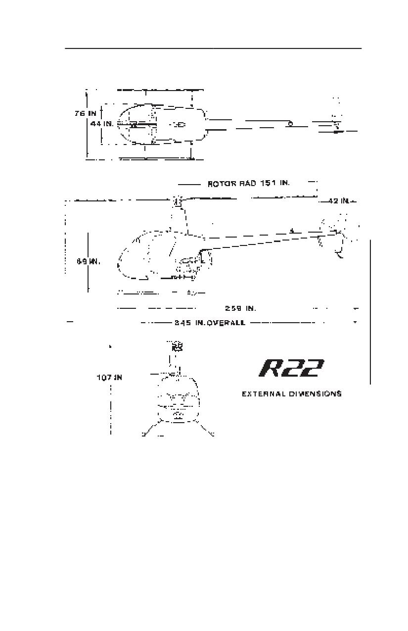
THREE-VIEW OF R22 HELICOPTER
REVISED: 6 JULY 1995
1-3
ROBINSON
SECTION 1
R22 SERIES
GENERAL
DESCRIPTIVE DATA
MAIN ROTOR
Articulation
Free to teeter and cone,
rigid inplane
Number of Blades
2
Diameter
25 feet 2 inches
Blade Chord
7.2 inches inboard,
7.7 inches outboard
Blade Twist
-8 degrees
Tip Speed at 104% RPM
698 feet per second
TAIL ROTOR
Articulation
Free to teeter, rigid inplane
Number of Blades
2
Diameter
42 inches
Blade Chord
4 inches (constant)
Blade Twist
0 degrees
Precone Angle
1 degree 11 minutes
Tip Speed at 104% RPM
622 feet per second
DRIVE SYSTEM
Engine to Upper Sheave:
Two double Vee-belts with
.8536:1 speed reducing
ratio
Upper Sheave to Drive Line: Sprag-type overrunning
clutch
Drive Line to Main Rotor:
Spiral-bevel gears with
11:47 speed reducing ratio
Drive Line to Tail Rotor:
Spiral-bevel gears with 3:2
speed increasing ratio
REVISED: 11 MAY 2020
1-4
ROBINSON
SECTION 1
R22 SERIES
GENERAL
PERFORMANCE DEFINITIONS (cont’d)
OAT Outside Air Temperature
CAT
Carburetor Air Temperature
CHT
Cylinder Head Temperature
GPH
Gallons Per Hour
AGL
Above Ground Level
IGE
In Ground Effect
OGE
Out of Ground Effect
ALT
Alternator
WEIGHT AND BALANCE DEFINITIONS
Reference
A vertical plane from which horizontal
Datum
distances are measured for balance
purposes. The longitudinal reference datum
is 100 inches forward of the main rotor
shaft centerline for the R22.
Station
Fore-and-aft location along the helicopter
fuselage given in terms of distance in inches
from the longitudinal reference datum.
Arm
Horizontal distance from a reference datum
to the center of gravity (CG) of an item.
Moment
The weight of an item multiplied by its arm.
Center of
Location along the fuselage (usually
Gravity (CG)
expressed in inches from the reference datum)
at which the helicopter would balance. CG
is calculated by dividing the total helicopter
moment by total helicopter weight.
CG Limits
Extreme CG locations within which the heli-
copter must be operated at a given weight.
Usable Fuel
Fuel available for flight planning.
Unusable Fuel
Fuel remaining in the tank that cannot
reliably provide uninterrupted fuel flow in
the critical flight attitude.
Standard
Weight of standard helicopter including
Empty Weight
unusable fuel, full operating fluids, and full
engine oil.
Basic
Standard empty weight plus weight of
Empty Weight
installed optional equipment.
Payload
Weight of occupants, cargo, and baggage.
Useful Load
Difference between maximum gross weight
and basic empty weight.
REVISED: 5 MAR 2015
1-7
ROBINSON
SECTION 1
R22 SERIES
GENERAL
CONVERSION TABLES
METRIC TO ENGLISH
Multiply
By
To Obtain
centimeters (cm)
0.3937
inches (in)
kilograms (kg)
2.2046
pounds (lb)
kilometers (km)
0.5400
nautical miles (nm)
kilometers (km)
0.6214
statute miles (mi)
liters (I)
0.2642
gallons, U.S. (gal)
liters (I)
1.0567
quarts (qt)
meters (m)
3.2808
feet (ft)
millibars (mb)
0.0295
inches mercury (in. Hg)
ENGLISH TO METRIC
Multiply
By
To Obtain
feet (ft)
0.3048
meters (m)
gallons, U.S. (gal)
3.7854
liters (I)
inches (in)
2.5400
centimeters (cm)
inches (in)
25.4000
millimeters (mm)
inches mercury (in. Hg)
33.8638
millibars (mb)
nautical miles (nm)
1.8520
kilometers (km)
pounds (lb)
0.4536
kilograms (kg)
quarts (qt)
0.9464
liters (I)
statute miles (mi)
1.6093
kilometers (km)
1 nautical mile = 1.1508 statute miles
1 statute mile = 0.8690 nautical mile
TEMPERATURE
°F = 9/5 (°C) + 32
°C = 5/9 (°F - 32)
REVISED: 5 MAR 2015
1-8
ROBINSON
SECTION 2
R22 SERIES
LIMITATIONS
SECTION 2
LIMITATIONS
GENERAL
This section includes operating limitations, instrument
markings, and basic placards required for safe operation
of the helicopter, its engine, and other standard systems.
The helicoper is approved as a normal category rotorcraft
under FAA Type Certificate No. H10WE as Models R22,
R22 Alpha, R22 Beta, and R22 Mariner.
COLOR CODE FOR INSTRUMENT MARKINGS
Red
Operating limit. Edge of red line indicates limit.
Pointer should not enter red during normal
operation.
Yellow Precautionary or special operating procedure
range.
Green
Normal operating range.
AIRSPEED LIMITS
NEVER-EXCEED AIRSPEED (VNE)
Up to 3000 feet density altitude: 102 KIAS
Above 3000 feet density altitude, see placards on page
2-11.
FAA APPROVED: 26 JUN 2012
2-1
ROBINSON
SECTION 2
R22 SERIES
LIMITATIONS
ROTOR SPEED LIMITS
TACHOMETER
ACTUAL
READING
RPM
Power On
Maximum
104%
530
Minimum*
101%**
515
Power Off
Maximum
110%
561
Minimum
90%
459
*Transient operation at lower RPM permitted for emergency
procedures training.
**97% (495 RPM) permitted on R22s with O-320 engine
and tachometer with 97% to 104% green arc installed.
POWERPLANT LIMITATIONS
ENGINE
One Lycoming Model O-320 or O-360
OPERATING LIMITS
Engine Maximum Speed
2652 RPM (104%)
Cylinder Head Max Temperature
500°F (260°C)
Oil Maximum Temperature
245°F (118°C)
Oil Pressure***
Minimum during idle
25 psi
Minimum during flight
55 psi
Maximum during flight
95 psi
Maximum during start & warm up
115 psi
Oil Quantitiy, minimum for takeoff
4 qt (3.8 liters)
Manifold Pressure: See placards on pages 2-10 and 2-11
for MAP schedules.
***These limits apply to all engines. Earlier oil pressure
gages show green arc from 60 to 90 psi and red line
at 100 psi. Regulations require that limits indicated by
installed gage are not exceeded.
FAA APPROVED: 26 OCT 2016
2-2
ROBINSON
SECTION 2
R22 SERIES
LIMITATIONS
WEIGHT LIMITS
Maximum gross weight - Standard & HP 1300 lb (590 kg)
Maximum gross weight - Alpha, Beta,
and Beta II
1370 lb (622 kg)
Minimum gross weight
920 lb (417 kg)
Maximum per seat
including baggage compartment
240 lb (109 kg)
Maximum in either baggage compartment
50 lb (23 kg)
CENTER OF GRAVITY LIMITS
See figures on pages 2-4 and 2-5. Reference datum is 100
inches forward of main rotor shaft centerline.
NOTE
With both doors installed, a solo pilot
plus baggage weight of 135 lb (61 kg) or
greater will ensure CG within limits. For
lower weight, compute weight and balance;
removable ballast may be required to obtain
CG at or forward of aft limit. (See Loading
Instructions in Section 6.)
FAA APPROVED: 5 MAR 2015
2-3
ROBINSON
SECTION 2
MODEL R22
LIMITATIONS
R22 ALPHA, BETA, AND BETA II
CENTER OF GRAVITY LIMITS
FAA APPROVED: 1 JUL 2005
2-5
ROBINSON
SECTION 2
R22 SERIES
LIMITATIONS
FLIGHT AND MANEUVER LIMITATIONS
Aerobatic flight prohibited.
CAUTION
Abrupt control inputs may produce high fatigue
stresses and cause catastrophic failure of a critical
component.
Low-G cyclic pushovers prohibited.
CAUTION
A pushover (forward cyclic maneuver) performed
from level flight or following a pull-up causes a
low-G (near weightless) condition which can result
in catastrophic loss of lateral control. To eliminate
a low-G condition, immediately apply gentle aft
cyclic. Should a right roll commence during a
low-G condition, apply gentle aft cyclic to reload
rotor before applying lateral cyclic to stop the roll.
Flight prohibited with governor selected off, with
exceptions for in-flight system malfunction or emergency
procedures training.
Flight in known icing conditions prohibited.
Maximum operating density altitude 14,000 feet.
Alternator, RPM governor, low rotor RPM warning system,
and OAT gage must be operational for dispatch.
Minimum crew is one pilot in the right seat. A flight
instructor may act as pilot in command from the left seat.
Solo flight from right seat only.
Left seat belt must be buckled.
Operation approved with either or both cabin doors
removed. Loose items in cabin must be properly secured
during doors-off flight.
A functioning headset must be worn by each pilot.
FAA APPROVED: 11 MAY 2020
2-6
ROBINSON
SECTION 2
R22 SERIES
LIMITATIONS
KINDS OF OPERATION LIMITATIONS
VFR day and night operations are approved.
VFR operation at night is permitted only when landing,
navigation, instrument, and anti-collision lights are opera-
tional. Orientation during night flight must be maintained
by visual reference to ground objects illuminated solely by
lights on the ground or adequate celestial illumination.
Note: There may be additional requirements in countries
outside the United States.
FUEL LIMITATIONS
APPROVED FUEL GRADES
Grade
Color
Specification
100
Green
100LL
Blue
ASTM D910
100VLL
Blue
UL 91
Clear to
Yellow
ASTM D7547
UL 94
(no dye)
Clear to
HJELMCO
Hjelmco Oil, Inc.
Yellow
91/96 UL
Sollentuna, Sweden
(no dye)
TU 38.5901481-96
91
Yellow
Ukrainian National
Standard
B91/115
Green
GOST 1012-72
Russian National
B95/130
Amber
Standard
FAA APPROVED: 20 JUN 2019
2-7
ROBINSON
SECTION 2
R22 SERIES
LIMITATIONS
FUEL LIMITATIONS (cont’d)
FUEL CAPACITY
Total Capacity
Usable Capacity
US gallons (liters) US gallons (liters)
Tanks with bladders:
Main tank
18.3 (69)
16.9 (64)
Auxiliary tank
9.7 (37)
9.4 (36)
Combined capacity
28.0 (106)
26.3 (100)
Tanks without bladders:
Main tank
19.8 (75)
19.2 (73)
Auxiliary tank
10.9 (41)
10.5 (40)
Combined capacity
30.7 (116)
29.7 (112)
Note: Per R22 Service Bulletin SB-109A, fuel tanks without
bladders should no longer be in service.
INSTRUMENT MARKINGS
AIRSPEED INDICATOR
Green arc
50 to 102 KIAS
Red line
102 KIAS
ROTOR TACHOMETER
Yellow arc
60 to 70%
Lower red line
90 %
Lower Yellow arc
90 to 101%*
Green arc
101 to 104%*
Upper Yellow arc
104 to 110%
Upper red line
110%
ENGINE TACHOMETER
Yellow arc
60 to 70%
Lower red arc
90 to 101%*
Green arc
101 to 104%*
Upper red arc
104 to 110%
*R22s with O-320 engine may have tachometer with green
arc from 97% to 104% RPM.
FAA APPROVED: 11 MAY 2020
2-8
ROBINSON
SECTION 2
MODEL R22
LIMITATIONS
PLACARDS (cont’d)
R22 Beta II
O-360-J2A Engine
All R22s
except Beta II
R22 Beta II
FAA APPROVED: 13 OCT 2000
2-11
ROBINSON
SECTION 2
R22 SERIES
LIMITATIONS
PLACARDS (cont’d)
Near main fuel tank filler cap:
FUEL
100 OCT MIN GRADE AVIATION GASOLINE
or
FUEL
91/96 MIN GRADE AVIATION GASOLINE
or
FUEL
AVIATION GASOLINE - GRADE 100LL
OR SEE PILOT’S HANDBOOK
or
R22s with O-320-A2B or -A2C engine may have:
FUEL
80/87 MIN GRADE AVIATION GASOLINE
Near aux fuel tank filler cap:
AUX FUEL
100 OCT MIN GRADE AVIATION GASOLINE
or
AUX FUEL
91/96 MIN GRADE AVIATION GASOLINE
or
AUX FUEL
AVIATION GASOLINE - GRADE 100LL
OR SEE PILOT’S HANDBOOK
FAA APPROVED: 20 JUN 2019
2-12
ROBINSON
SECTION 2
R22 SERIES
LIMITATIONS
PLACARDS (cont’d)
Near shut-off valve:
FUEL
ON
OFF
Near main tank fuel gage:
For bladder-style tank
16.9 US GAL
For aluminum (non-bladder) tank
19.2 US GAL
Near aux tank fuel gage:
For bladder-style tank
AUX 9.4 US GAL
For aluminum (non-bladder) tank
AUX 10.5 US GAL
In clear view of both occupants:
NO SMOKING
In clear view of pilot (Alpha, Beta, and Beta II with aft
battery installations):
MINIMUM SOLO PILOT WEIGHT 130 LB
(135 LB WITH FULL AUX FUEL)
or
SEE PILOT’S HANDBOOK FOR SOLO PILOT
WEIGHT LESS THAN 135 LB (61KG)
FAA APPROVED: 26 OCT 2016
2-13
ROBINSON
SECTION 2
R22 SERIES
LIMITATIONS
PLACARDS (cont’d)
In clear view of pilot:
THIS ROTORCRAFT APPROVED FOR
DAY AND NIGHT VFR OPERATIONS
LOW-G PUSHOVERS PROHIBITED
On left-hand cyclic:
SOLO FROM RIGHT SEAT ONLY
On or near collective controls:
NO STOWAGE
KEEP AREA CLEAR
Inside each baggage compartment:
CAUTION
DO NOT EXCEED ANY OF THE FOLLOWING:
• COMPARTMENT CAPACITY: 50 LB MAX
• COMBINED SEAT PLUS COMPARTMENT: 240 LB MAX
• ROTORCRAFT GROSS WEIGHT LIMIT
SEE ROTORCRAFT FLIGHT MANUAL FOR ADDITIONAL
INSTRUCTIONS
On carburetor air temperature gage:
CAUTION
BELOW 18 IN. MP, IGNORE GAGE
& APPLY FULL CARB HEAT
Near heater push-pull control when heater is installed:
IN CASE OF ENGINE FIRE
PUSH HEATER CONTROL TO OFF
FAA APPROVED: 26 OCT 2016
2-14
ROBINSON
SECTION 2
R22 SERIES
LIMITATIONS
INFORMATION PER FAA AD 95-26-04
The following limitations (1-3) are to be observed unless
the pilot manipulating the controls has logged 200 or more
flight hours in helicopters, at least 50 of which must be
in the RHC Model R22 helicopter, and has completed the
awareness training specified in Special Federal Aviation
Regulation (SFAR) No. 73, issued February 27, 1995.
1. Flight when surface winds exceed
25 knots,
including gusts, is prohibited.
2. Flight when surface wind gust spreads exceed 15
knots is prohibited.
3. Continued flight in moderate, severe, or extreme
turbulence is prohibited.
Adjust forward airspeed to between 60 knots indicated
airspeed (KIAS) and 0.7 Vne but no lower than 57 KIAS,
upon inadvertently encountering moderate, severe, or
extreme turbulence.
Note: Moderate turbulence is turbulence that causes: (1)
changes in altitude or attitude; (2) variations in indicated
airspeed; and (3) aircraft occupants to feel definite strains
against seat belts.
RHC NOTE
This AD is issued by the FAA and is applicable to
US-registered helicopters.
FAA APPROVED: 20 JUN 2019
2-15
INTENTIONALLY BLANK
ROBINSON
SECTION 3
R22 SERIES
EMERGENCY PROCEDURES
SECTION 3
EMERGENCY PROCEDURES
CONTENTS
Page
Definitions
3-1
Power Failure - General
3-1
Power Failure Above 500 Feet AGL
3-2
Power Failure Between 8 Feet and 500 Feet AGL
3-2
Power Failure Below 8 Feet AGL
3-3
Maximum Glide Distance Configuration
3-3
Air Restart Procedure
3-3
Emergency Water Landing - Power Off
3-4
Emergency Water Landing - Power On
3-4
Loss of Tail Rotor Thrust in Forward Flight
3-5
Loss of Tail Rotor Thrust in Hover
3-5
Headset Audio Failure
3-5
Engine Fire During Start on Ground
3-6
Engine Fire in Flight
3-6
Electrical Fire in Flight
3-6
Tachometer Failure
3-7
Governor Failure
3-7
Warning/Caution Lights
3-8
Audio Alerts
3-10
Information per FAA AD 95-26-04
3-11
FAA APPROVED: 11 MAY 2020
3-i
INTENTIONALLY BLANK
ROBINSON
SECTION 3
R22 SERIES
EMERGENCY PROCEDURES
SECTION 3
EMERGENCY PROCEDURES
DEFINITIONS
Land Immediately - Land on the nearest clear area where
a safe normal landing can be performed. Be prepared to
enter autorotation during approach, if required.
Land as soon as practical - Landing site is at pilot’s
discretion based on nature of problem and available landing
areas. Flight beyond nearest airport is not recommended.
POWER FAILURE - GENERAL
A power failure may be caused by either an engine or
drive system failure and will usually be indicated by the
low RPM horn. An engine failure may be indicated by a
change in noise level, nose left yaw, an oil pressure light,
or decreasing engine RPM. A drive system failure may
be indicated by an unusual noise or vibration, nose right
or left yaw, or decreasing rotor RPM while engine RPM is
increasing.
In case of power failure, immediately lower collective to
enter autorotation.
CAUTION
Aft cyclic is required when collective is
lowered at high airspeed.
CAUTION
Do not apply aft cyclic during touchdown or
ground slide to prevent possible blade strike
to tailcone.
FAA APPROVED: 26 OCT 2016
3-1
ROBINSON
SECTION 3
R22 SERIES
EMERGENCY PROCEDURES
POWER FAILURE ABOVE 500 FEET AGL
1. Lower collective immediately to maintain rotor RPM.
2. Establish a steady glide at approximately 65 KIAS. (For
maximum glide distance, see page 3-3.)
3. Adjust collective to keep RPM between 97 and 110%
or apply full down collective if light weight prevents
attaining above 97%.
4. Select landing spot and, if altitude permits, maneuver
so landing will be into wind.
5. A restart may be attempted at pilot’s discretion if
sufficient time is available (See “Air Restart Procedure”,
page 3-3).
6. If unable to restart, turn unnecessary switches and fuel
valve off.
7. At about 40 feet AGL, begin cyclic flare to reduce rate
of descent and forward speed.
8. At about 8 feet AGL, apply forward cyclic to level ship and
raise collective just before touchdown to cushion landing.
Touch down in level attitude with nose straight ahead.
POWER FAILURE BETWEEN 8 FEET AND 500 FEET AGL
1. Lower collective immediately to maintain rotor RPM.
2. Adjust collective to keep RPM between 97 and 110%
or apply full down collective if light weight prevents
attaining above 97%.
3. Maintain airspeed until ground is approached, then begin
cyclic flare to reduce rate of descent and forward speed.
4. At about 8 feet AGL, apply forward cyclic to level ship and
raise collective just before touchdown to cushion landing.
Touch down in level attitude and nose straight ahead.
FAA APPROVED: 21 FEB 2014
3-2
ROBINSON
SECTION 3
R22 SERIES
EMERGENCY PROCEDURES
EMERGENCY WATER LANDING - POWER OFF
1. Follow same procedures as for power failure over land
until contacting water. If time permits, unlatch doors
prior to water contact.
2. Apply lateral cyclic when aircraft contacts water to stop
rotors.
3. Release seat belt and quickly clear aircraft when rotors
stop.
EMERGENCY WATER LANDING - POWER ON
1. Descend to hover above water.
2. Unlatch doors.
3. Passenger exit aircraft.
4. Fly to safe distance from passenger to avoid possible
injury by rotors.
5. Switch battery and alternator OFF.
6. Roll throttle off into overtravel spring.
7. Keep aircraft level and apply full collective as aircraft
contacts water.
8. Apply lateral cyclic to stop rotors.
9. Release seat belt and quickly clear aircraft when rotors
stop.
FAA APPROVED: 21 FEB 2014
3-4
ROBINSON
SECTION 3
R22 SERIES
EMERGENCY PROCEDURES
LOSS OF TAIL ROTOR THRUST IN FORWARD FLIGHT
Failure is usually indicated by nose right yaw which cannot
be corrected by applying left pedal.
1. Immediately enter autorotation.
2. Maintain at least 70 KIAS if practical.
3. Select landing site, roll throttle off into overtravel
spring, and perform autorotation landing.
NOTE
When a suitable landing site is not available,
the vertical stabilizers may permit limited
controlled flight at low power settings and
airspeeds above 70 KIAS; however, prior to
reducing airspeed, enter full autorotation.
LOSS OF TAIL ROTOR THRUST IN HOVER
Failure is usually indicated by nose right yaw which cannot
be stopped by applying left pedal.
1. Immediately roll throttle off into overtravel spring and
allow aircraft to settle.
2. Raise collective just before touchdown to cushion
landing.
HEADSET AUDIO FAILURE
If headset audio fails, land as soon as practical.
CAUTION
For aircraft which provide low RPM horn
through the audio system, pilot will not hear
horn with a failed headset.
FAA APPROVED: 11 MAY 2020
3-5
ROBINSON
SECTION 3
R22 SERIES
EMERGENCY PROCEDURES
ENGINE FIRE DURING START ON GROUND
1. Cranking - Continue and attempt to start which would
suck flames and excess fuel into engine.
2. If engine starts, run at 50-60% RPM for a short time.
3. Fuel mixture - OFF.
4. Fuel valve - OFF.
5. Battery switch - OFF.
6. If time permits, apply rotor brake to stop rotors.
7. Exit helicopter.
ENGINE FIRE IN FLIGHT
1. Enter autorotation.
2. Cabin heat - OFF (if installed and time permits).
3. Cabin vent - ON (if time permits).
4. If engine is running, perform normal landing, then fuel
mixture OFF and fuel valve OFF.
If engine stops running, fuel valve OFF and complete
autorotation landing.
5. Battery switch - OFF.
6. If time permits, apply rotor brake to stop rotors.
7. Exit helicopter.
ELECTRICAL FIRE IN FLIGHT
1. Battery and alternator switches - OFF.
2. Open cabin vents.
3. Land immediately.
4. Fuel mixture OFF and fuel valve OFF.
5. If time permits, apply rotor brake to stop rotors.
6. Exit helicopter.
CAUTION
Low RPM warning system and governor
are inoperative with battery and alternator
switches both off.
FAA APPROVED: 26 OCT 2016
3-6
ROBINSON
SECTION 3
R22 SERIES
EMERGENCY PROCEDURES
TACHOMETER FAILURE
If rotor or engine tach malfunctions in flight, use remaining
tach to monitor RPM. If it is not clear which tach is
malfunctioning or if both tachs malfunction, allow governor
to control RPM and land as soon as practical.
NOTE
Each tach, the governor, and the low RPM
horn are on separate power circuits. A special
circuit allows the battery to supply power
to the tachs with the battery and alternator
switches both off.
GOVERNOR FAILURE
If engine RPM governor malfunctions, grip throttle firmly to
override the governor, then switch governor off. Complete
flight using manual throttle control.
FAA APPROVED: 20 JUN 2019
3-7
ROBINSON
SECTION 3
MODEL R22
EMERGENCY PROCEDURES
WARNING/CAUTION LIGHTS
NOTE
If a light causes excessive glare at night,
bulb may be unscrewed or circuit breaker
pulled to eliminate glare during landing.
OIL
Indicates loss of engine power or oil pressure.
Check engine tach for power loss. Check
oil pressure gage and, if pressure loss is
confirmed, land immediately.
Continued
operation without oil pressure will cause
serious engine damage and engine failure may
occur.
MR TEMP Indicates excessive temperature of main rotor
gearbox. See note below.
MR CHIP Indicates metallic particles in main rotor
gearbox. See note below.
TR CHIP Indicates metallic particles in tail rotor gearbox.
See note below.
NOTE
If light is accompanied by any indication
of a problem such as noise, vibration, or
temperature rise, land immediately. If
there is no other indication of a problem,
land as soon as practical.
Break-in fuzz will occasionally activate
chip lights. If no metal chips or slivers
are found on detector plug, clean and
reinstall (tail rotor gearbox must be
refilled with new oil). Hover for at least
30 minutes. If chip light comes on again,
replace gearbox before further flight.
FAA APPROVED: 13 OCT 2000
3-8
ROBINSON
SECTION 3
R22 SERIES
EMERGENCY PROCEDURES
WARNING/CAUTION LIGHTS (cont’d)
LOW
Indicates approximately one gallon of usable
FUEL
fuel remaining for all-aluminum fuel tanks or 1.5
gallons for bladder-style tanks. The engine will
run out of fuel after approximately five minutes
at cruise power for aircraft with all-aluminum
tanks or ten minutes with bladder-style tanks.
CAUTION
Do not use low fuel caution light as
a working indication of fuel quantity.
CLUTCH
Indicates clutch actuator circuit is on, either
engaging or disengaging clutch. When switch
is in the ENGAGE position, light stays on until
belts are properly tensioned. Never take off
before light goes out.
NOTE
Clutch light may come on momentarily
during run-up or during flight to
retension belts as they warm-up and
stretch slightly. This is normal. If,
however, the light flickers or comes
on in flight and does not go out within
10 seconds, pull CLUTCH circuit
breaker and land as soon as practical.
Reduce power and land immediately
if there are other indications of drive
system failure (be prepared to enter
autorotation).
Have drive system
inspected for a possible malfunction.
ALT
Indicates low voltage and possible alternator
failure. Turn off nonessential electrical equipment
and switch ALT off and back on after one second
to reset alternator control unit. If light stays on,
land as soon as practical. Continued flight without
functioning alternator can result in loss of power
to tachometers, producing a hazardous flight
condition.
FAA APPROVED: 26 OCT 2016
3-9
ROBINSON
SECTION 3
R22 SERIES
EMERGENCY PROCEDURES
WARNING/CAUTION LIGHTS (cont’d)
STARTER
Indicates starter motor is engaged. If light does
ON
not go out when ignition switch is released
from start position, immediately pull mixture
off and turn battery switch off. Have starter
motor serviced.
LOW RPM
Indicates rotor speed below 97% RPM. To
restore RPM, immediately lower collective,
roll throttle on and, in forward flight, apply aft
cyclic. Light is disabled when collective is full
down.
GOV OFF
Indicates engine RPM governor is switched off.
CARBON
Indicates elevated levels of carbon monoxide
MONOXIDE
(CO) in cabin. Shut off heater and open nose
(if installed)
and door vents. If hovering, land or transition
to forward flight. If symptoms of CO poisoning
(headache, drowsiness, dizziness) accompany
light, land immediately.
BRAKE
Indicates rotor brake is engaged. Release
immediately in flight or before starting engine.
FULL
Indicates engine near full throttle. The governor
THROTTLE
will be ineffective because it cannot increase
(if installed)
throttle to maintain RPM. Lower collective as
required to extinguish light.
AUDIO ALERTS
LOW RPM HORN
Horn is provided by a speaker in the side of the instrument
console on earlier aircraft or through the audio system on
later aircraft. The horn activates simultaneously with
the LOW RPM caution light and indicates rotor speed
below 97% RPM. To restore RPM, lower collective, roll
throttle on and, in forward flight, apply aft cyclic. Horn
and Light are disabled when collective is full down.
FAA APPROVED: 11 MAY 2020
3-10
ROBINSON
SECTION 3
R22 SERIES
EMERGENCY PROCEDURES
AUDIO ALERTS (Cont’d)
HIGH RPM WARBLE
On later aircraft, a warble (high/low tone) in the audio
system indicates rotor speed is approaching 110% RPM
limit. Raise collective as required to control RPM.
INFORMATION PER FAA AD 95-26-04
1) RIGHT ROLL IN LOW “G” CONDITION
Gradually apply aft cyclic to restore positive “G”
forces and main rotor thrust. Do not apply lateral
cyclic until positive “G” forces have been established.
2) UNCOMMANDED PITCH, ROLL. OR YAW RESULTING
FROM FLIGHT IN TURBULENCE.
Gradually apply controls to maintain rotor RPM,
positive “G” forces, and to eliminate sideslip.
Minimize cyclic control inputs in turbulence; do not
overcontrol.
3) INADVERTENT ENCOUNTER WITH MODERATE,
SEVERE, OR EXTREME TURBULENCE.
If the area of turbulence is isolated, depart the area;
otherwise, land the helicopter as soon as practical.
FAA APPROVED: 11 MAY 2020
3-11
INTENTIONALLY BLANK
ROBINSON
SECTION 4
R22 SERIES
NORMAL PROCEDURES
SECTION 4
NORMAL PROCEDURES
CONTENTS
Page
Recommended Airspeeds
4-1
Daily or Preflight Checks
4-1
Before Starting Engine
4-6
Starting Engine and Run-Up
4-7
Takeoff Procedure
4-8
Cruise
4-8
Doors-Off Operation
4-9
Practice Autorotation - Power Recovery
4-9
Practice Autorotation - With Ground Contact
4-10
Use of Carburetor Heat
4-11
Use of Carb Heat Assist
4-11
Descent, Approach, and Landing
4-12
Shutdown Procedure
4-13
Noise Abatement
4-14
Information per FAA AD 95-26-04
4-15
FAA APPROVED: 26 OCT 2016
4-i
INTENTIONALLY BLANK
ROBINSON
SECTION 4
R22 SERIES
NORMAL PROCEDURES
SECTION 4
NORMAL PROCEDURES
RECOMMENDED AIRSPEEDS
Takeoff and Climb
60 KIAS
Maximum Rate of Climb (VY )
53 KIAS
Maximum Range
83 KIAS*
Significant Turbulence
60 to 70 KIAS*
Landing Approach
60 KIAS
Autorotation
60 to 70 KIAS*
* Certain conditions may require lower airspeed.
See Vne placards in Section 2.
DAILY OR PREFLIGHT CHECKS
Remove ground handling wheels and all covers and
tiedowns. Remove even small accumulations of frost, ice,
or snow, especially from rotor blades. Check maintenance
records to verify aircraft is airworthy.
Check general condition of aircraft and verify no visible
damage, fluid leakage, or abnormal wear. Verify no fretting
at rivets and seams where parts are joined together.
Fretting of aluminum parts produces a fine black powder
while fretting of steel parts produces a reddish-brown or
black residue. Verify Telatemps show no temperature
increase that cannot be attributed to a change in operating
conditions (mechanics draw a reference line to the right
of the highest temperature square which has darkened in
operation). Verify torque stripes on critical fasteners are
not broken or missing.
FAA APPROVED: 11 MAY 2020
4-1
ROBINSON
SECTION 4
R22 SERIES
NORMAL PROCEDURES
DAILY OR PREFLIGHT CHECKS (cont’d)
1. Cowl Doors
Battery switch
ON
Oil pressure and alternator lights
ON
Warning light test switches
Push to test
Fuel quantity
Check gages
Battery switch
OFF
Aux fuel tank quantity
Check
Fuel filler cap
Tight
Aux fuel tank
No leaks
Fuel lines
No leaks
Fuel tank sump drain(s)
Sample
Gearbox oil
Full, no leaks
Rotor brake
Actuation normal
Flex coupling
No cracks, nuts secure
Yoke flanges
No cracks
Gearbox Telatemp
Normal
Sprag clutch
No leaks
Static source
Clear
Control rod ends
Free without looseness
Steel tube frame
No cracks
All fasteners
Secure
Tail rotor control
No interference
Cowl doors
Latched
2. Engine Right Side
Carb air ducts
Secure
Carb heat scoop
Secure
Engine sheet metal
No cracks
Electrical terminals
Tight
Fuel line
No leaks
Oil cooler door
Check
Oil lines
No leaks or chafing
Exhaust system
No cracks
Engine general condition
Check
V-belt condition
Check
V-belt slack
Check
Sprag clutch
No leaks
Upper bearing
No leaks
Telatemp - upper bearing
Normal
FAA APPROVED: 11 MAY 2020
4-2
ROBINSON
SECTION 4
R22 SERIES
NORMAL PROCEDURES
DAILY OR PREFLIGHT CHECKS (cont’d)
2. Engine Right Side (cont’d)
Upper Sheave Condition
Check
Lower sheave groove wear
Smooth & Uniform
Flex coupling
No cracks, nuts secure
Yoke flanges
No cracks
Steel tube frame
No cracks
Tail rotor control
No interference
3. Engine Rear
Cooling fan nut
Pin in line with marks
Cooling fan
No cracks
Fan scroll
No cracks
Teletemps - lower bearing
Normal
Lower bearing
No leaks
4. Empennage
Tail surfaces
No cracks
Fasteners
Secure
Position light
Check
5. Tail Rotor
Gearbox Telatemp
Normal
Gearbox
Oil visible, no leaks
Blades
Clean and no damage/cracks
Pitch links
No looseness
Teeter bearings
Check condition
Teeter bearing bolt
Does not rotate
Control bellcrank
Free without looseness
6. Tailcone
Skins
No cracks or dents
Strobe light condition
Check
Antenna
Check
FAA APPROVED: 11 MAY 2020
4-3
ROBINSON
SECTION 4
R22 SERIES
NORMAL PROCEDURES
DAILY OR PREFLIGHT CHECKS (cont’d)
7. Engine Left Side
Engine oil
4-6 qt
Oil filter (if installed)
Secure, no leaks
Fuel lines
No leaks
Gascolator drain
Sample
Throttle linkage
Operable
Battery and relay (if located here)
Secure
Alternator belt tension
Check
Steel tube frame
No cracks
Engine sheet metal
No cracks
Exhaust system
No cracks
Engine general condition
Check
8. Main Fuel Tank
Quantity
Check
Filler cap
Tight
Leakage
None
9. Main Rotor
CAUTION
Do not pull down on blades to teeter
rotor. To lower a blade, push up on
opposite blade.
Blades
Clean and no damage/cracks
CAUTION
Verify erosion on lower surface of
blades has not exposed skin-to-spar
bond line. Reference Rotor Systems
description in Section 7.
Pitch change boots
No leaks
Main hinge bolts
Cotter pins installed
All rod ends
Free without looseness
All fasteners
Secure
Swashplate scissors
No excessive looseness
FAA APPROVED: 11 MAY 2020
4-4
ROBINSON
SECTION 4
R22 SERIES
NORMAL PROCEDURES
DAILY OR PREFLIGHT CHECKS (cont’d)
10. Fuselage Left Side
Baggage compartment
Check
Removable controls
Secure if installed
Collective control
Clear
Seat Belt
Check condition and fastened
Door
Unlocked and latched
Door hinge safety pins
Installed
Landing gear
Check
Position light
Check
11. Nose Section
Pitot tube
Clear
Windshield condition and cleanliness
Check
Landing lights
Check
Yaw string
Check
12. Fuselage Right Side
Landing gear
Check
Position light
Check
Door hinge safety pins
Installed
Baggage compartment
Check
13. Cabin Interior
Loose articles
Removed or stowed
Seat belt
Check condition
Instruments, switches, and controls . . Check condition
Clock
Functioning
CAUTION
For helicopters with removable con-
trols, remove left seat controls if per-
son in that seat is not a rated helicopter
pilot.
CAUTION
Be sure rotor blades are approximately
level to avoid possible tailcone strike.
FAA APPROVED: 11 MAY 2020
4-5
ROBINSON
SECTION 4
R22 SERIES
NORMAL PROCEDURES
DAILY OR PREFLIGHT CHECKS (cont’d)
CAUTION
When flying solo, fill left baggage compartment
to capacity before using right compartment.
Avoid placing objects in compartments which
could injure occupant if seat collapses during
a hard landing.
CAUTION
Shorter pilots may require cushion to obtain
full travel of all controls. Verify aft cyclic
travel is not restricted.
BEFORE STARTING ENGINE
Seat belts
Fastened
Fuel shut-off valve
ON
Cyclic/collective friction
OFF
Cyclic, collective, pedals
Full travel free
Throttle
Full travel free
Collective
Full down, friction ON
Cyclic
Neutral, friction ON
Pedals
Neutral
Rotor brake
Disengaged
Circuit breakers
In
Carb heat
OFF
Mixture
Full rich
Mixture guard*
Installed
Primer (if installed)
Down and locked
Landing lights
OFF
Avionics switch (if installed)
OFF
Clutch
Disengaged
Altimeter
Set
Governor switch
ON
* Mixture guard is not used on aircraft with vernier mixture
control on console face.
FAA APPROVED: 21 FEB 2014
4-6
ROBINSON
SECTION 4
R22 SERIES
NORMAL PROCEDURES
STARTING ENGINE AND RUN-UP
Throttle twists for priming
As required
Throttle
Closed
Battery, strobe switches
ON
Area
Clear
Ignition switch
Start, then Both
Starter-On light
Out
Set engine RPM
50 to 60%
Clutch switch
Engaged
Blades turning
Less than 5 seconds
Alternator switch
ON
Oil pressure within 30 seconds
25 psi minimum
Avionics, headsets
ON
Audio alert (if equipped)
Test
Wait for clutch light out
Circuit breakers in
Warm-up RPM
70 to 75%
Engine gages
Green
Mag drop at 75% RPM
7% max in 2 seconds
Carb heat
CAT rise/drop, set as required
Sprag clutch check
Needles split
Doors (if installed)
Closed and latched
Limit MAP chart
Check
Cyclic/collective friction
OFF
Governor On, increase throttle
RPM 102-104%
Warning lights
Out
Lift collective slightly, reduce RPM
Horn/light at 97%
CAUTION
For aircraft which provide low RPM horn
through the audio system, a headset for each
pilot is required to hear the horn.
CAUTION
Avoid continuous operation at rotor speed of
60 to 70% to minimize tail resonance.
CAUTION
On slippery surfaces, be prepared to counter
nose-right rotation with left pedal as governor
increases RPM.
FAA APPROVED: 11 MAY 2020
4-7
ROBINSON
SECTION 4
R22 SERIES
NORMAL PROCEDURES
TAKEOFF PROCEDURE
1. Verify doors latched, governor ON, and RPM stabilized
at 102 to 104%.
2. Clear area. Slowly raise collective until aircraft is light
on skids. Reposition cyclic as required for equilibrium,
then gently lift aircraft into hover.
3. Check gages in green and adjust carb heat if required.
4. Lower nose and accelerate to climb speed following
profile shown by height-velocity diagram in Section 5.
If RPM drops below 102%, lower collective.
CRUISE
1. Adjust carb heat if required. (See page 4-11.)
2. Verify RPM near top of green arc.
3. Set manifold pressure as desired with collective. Observe
MAP and airspeed limits.
4. Pull RT TRIM knob.
5. Verify gages in green, warning lights out.
CAUTION
In turbulence, reduce power and use a slower
than normal cruise speed. If turbulence is
significant or becomes uncomfortable for the
pilot, use 60 to 70 KIAS.
CAUTION
Exercise extreme care never to inadvertently
pull mixture control as engine stoppage will
result.
CAUTION
In-flight leaning with engine mixture control
is not recommended. Engine stoppage may
result as there is no propeller to keep engine
turning should overleaning occur.
FAA APPROVED: 26 OCT 2016
4-8
ROBINSON
SECTION 4
R22 SERIES
NORMAL PROCEDURES
DOORS-OFF OPERATION
Avoid removing left door to protect tail rotor from loose
objects. If left door must be removed, warn passenger
to secure loose objects and to keep head and arms inside
cabin to avoid high velocity airstream.
PRACTICE AUTOROTATION - POWER RECOVERY
1. Adjust carb heat if required. (See page 4-11.)
2. Lower collective to down stop and reduce throttle as
desired for tachometer needle separation.
CAUTION
To avoid inadvertent engine stoppage, do
not chop throttle to simulate a power failure.
Always roll throttle off smoothly. Recover
immediately if engine is rough or engine RPM
continues to drop.
NOTE
Governor is inactive below 80% engine RPM
regardless of governor switch position.
NOTE
When entering autorotation from above 4000
feet, reduce throttle slightly before lowering
collective to prevent engine overspeed.
3. Adjust collective to keep rotor RPM within limits and
adjust throttle for tachometer needle separation.
4. Keep airspeed 60 to 70 KIAS.
5. At about 40 feet AGL, begin cyclic flare to reduce rate
of descent and forward speed.
6. At about 8 feet AGL, apply forward cyclic to level
aircraft and raise collective to control descent. Add
throttle if required to keep RPM in green arc.
FAA APPROVED: 20 JUN 2019
4-9