Robinson R22 Helicopter. MAINTENANCE MANUAL (2018) - page 6
FIGURE 14-49 C831 GPS SCHEMATIC (GARMIN GTN 600 SERIES)
OCT 2018
Chapter 14 Electrical and Avionics Systems
Page 14.75
FIGURE 14-50 C831 GPS SCHEMATIC (GARMIN GTN 600 SERIES; EARLIER SHIPS)
Page 14.76
Chapter 14 Electrical and Avionics Systems
OCT 2018
FIGURE 14-51 C833 GPS SCHEMATIC (GARMIN 400 SERIES)
OCT 2018
Chapter 14 Electrical and Avionics Systems
Page 14.77
Intentionally Blank
Page 14.78
Chapter 14 Electrical and Avionics Systems
OCT 2018
CHAPTER 15
FURNISHINGS
Section Title
Page
15-00
Description
15.1
15-10
Seat Harnesses
15.1
15-20
Seat and Seat Back Assemblies
15.2
15-21
Seat Assemblies
15.2
15-22
Seat Back Assemblies
15.2
15-30
Carpet
15.4
15-40
Insulation (Foam and Headliner)
15.5
15-50
General Maintenance
15.6
15-51
Pilot’s Operating Handbook (POH) Strap Replacement
15.6
15-52
License Holder Replacement
15.6
15-53
Map Pocket Replacement
15.6
15-60
Emergency Equipment
15.7
15-61
Emergency Locator Transmitter (ELT)
15.7
15-62
Fire Extinguisher
15.8
OCT 2018
Chapter 15 Furnishings
Page 15.i
Intentionally Blank
Page 15.ii
Chapter 15 Furnishings
OCT 2018
CHAPTER 15
FURNISHINGS
15-00 Description
The seats are not adjustable but each helicopter is delivered with a cushion which can be
placed behind the pilot to position him farther forward. This allows shorter pilots to reach
the pedals, the cyclic grip in its most forward position, and controls on the center console.
Each seat is equipped with a combined lap belt and inertia reel shoulder strap. The inertia
reel is normally free but will lock if there is sudden movement as would occur in an accident.
A baggage compartment is located under each seat. Seat cushions hinge forward for
access.
15-10 Seat Harnesses
A. Removal
1. Hinge seat assemblies forward.
2. Remove hardware securing F628-8 buckle assemblies to inboard anchors. Remove
hardware securing lap belt fittings to outboard anchors.
3. Remove shoulder strap guide covers. Remove hardware securing guides to A259
bulkhead.
4. Remove inertia reel covers. Remove hardware securing reels to bulkhead. Remove
A628-6 connector assemblies.
B. Installation
1. Install hardware securing A628-6 connector assembly inertia reels to A259
bulkhead. Install reel covers. Verify security.
2. Install hardware securing shoulder strap guides to bulkhead. Standard torque bolts
per § 23-32. Install guide covers. Verify security.
3. Install hardware securing F628-8 buckle assemblies to inboard anchors; rotate
buckles 20° forward from vertical. Standard torque bolts per § 23-32. Verify
security.
4. Install hardware securing lap belt fittings to outboard anchors. Standard torque
bolts per § 23-32. Verify security.
OCT 2018
Chapter 15 Furnishings
Page 15.1
15-20 Seat and Seat Back Assemblies
15-21 Seat Assemblies
A. Removal
Remove hardware securing seat assembly to support and remove seat.
B. Installation
Position seat assembly on support and install hardware. Verify security.
15-22 Seat Back Assemblies
A. Removal
Left Seat Back
1. Remove screws securing pilot’s collective boot and ring to A654-4 (vertical)
panel assembly, remove ring, and unsnap boot. Remove screws securing panel
to cabin and remove panel.
2. Remove screws securing A670-1 (fuel) valve’s A798 plates to A003-13 seat
back assembly and remove A798-1 plate.
3. Tilt seat assembly forward and remove screws securing co-pilot’s collective
boot and ring to seat back, remove ring, and unsnap boot. Remove screws
securing seat back to cabin and remove seat back. (Remove A798-3 plate.)
Right Seat Back
1. Remove screws securing pilot’s collective boot and ring to A654-4 (vertical)
panel assembly, remove ring, and unsnap boot. Remove screws securing panel
to cabin and remove panel.
2. Remove screws securing A003-14 seat back assembly to cabin and remove
seat back.
Page 15.2
Chapter 15 Furnishings
OCT 2018
FIGURE 15-1 A798-1 PLATE ORIENTATION (VIEW LOOKING DOWN)
15-22 Seat Back Assemblies (continued)
B. Installation
Left Seat Back
1. Position A798-3 plate on A670-1 (fuel) valve. Tilt seat assembly forward
and position A003-13 seat back assembly on cabin and install screws. Verify
security.
2. Install screws securing co-pilot’s collective boot and ring to seat back and snap-
up boot. Verify security.
3. Refer to Figure 15-1. Install A798-1 plate on seat back as shown. Special
torque screws to 16 in.-lb.
4. Install screws securing A654-4 (vertical) panel assembly to cabin. Install screws
securing pilot’s collective boot and ring to panel and snap-up boot. Verify
security.
Right Seat Back
1. Refer to Figure 15-1. Tilt seat assembly forward and position A003-14 seat
back assembly on cabin and install screws. Verify security.
2. Install screws securing A654-4 (vertical) panel assembly to cabin. Install screws
securing pilot’s collective boot and ring to panel and snap-up boot. Verify
security.
OCT 2018
Chapter 15 Furnishings
Page 15.3
15-22 Seat Back Assemblies (continued)
C. Back Rest Assembly (Cushion) Replacement
1. Remove seat back assembly per Part A.
2. Drill out rivets securing back rest assembly (cushion) to seat back panel and
deburr holes. Remove cushion.
3. Center and straighten new back rest 1.00 ± 0.10 inch above top edge of seat
back panel. Match drill seat back panel #30 holes through back rest. Deburr
holes and clean up debris.
4. Attach back rest cushion to seat back panel with rivets. Verify security.
15-30 Carpet
A. Removal
1. Floor carpets: Remove hardware securing scuff plates (and carpet) to cabin floor
and remove scuff plates, if installed.
CAUTION
Use caution when removing adhered carpet if carpet is intended
for reuse.
2. Starting at corners, gently peel back carpet by hand, or with plastic wedge or putty
knife.
3. Dampen old adhesive with Dupont Prep-Sol (or equivalent) to facilitate removal.
B. Installation
1. Verify proper carpet fit. Trim as required (do not trim carpet welt).
2. Apply B270-8 adhesive to bonding surface and carpet backing. Press carpet to
surface, smooth wrinkles, and remove excess adhesive prior to curing.
3. Install hardware securing scuff plates (and carpet) to cabin floor if removed. Verify
security.
Page 15.4
Chapter 15 Furnishings
OCT 2018
15-40 Insulation (Foam and Headliner)
A. Removal
NOTE
Use caution not to damage surface underneath insulation when
removing insulation with tools.
NOTE
Insulation is installed using adhesive, except under seat
assemblies. Order new insulation as required; reuse of removed
insulation is not recommended.
1. Peel off insulation by hand.
2. Using plastic wedge or putty knife, carefully remove residual insulation and old
adhesive.
3. Wipe bonding surface with clean cloth, wet with acetone.
B. Installation
1. Verify proper insulation fit. Trim as required.
2. Apply B270-8 adhesive to bonding surface and insulation backing. Press insulation
to surface, smooth wrinkles, and remove excess adhesive prior to curing.
OCT 2018
Chapter 15 Furnishings
Page 15.5
15-50 General Maintenance
15-51 Pilot's Operating Handbook (POH) Strap Replacement
A. Removal
Remove POH. Drill out rivets securing POH retaining strap to chin and remove strap.
Deburr holes and clean up debris.
B. Installation
Cleco POH retaining strap to chin. Progressively remove clecos and install rivets.
Verify security. Install POH.
15-52 License Holder Replacement
A. Removal
Remove contents. Drill out rivets securing license holder to chin and remove license
holder. Deburr holes and clean up debris.
B. Installation
Cleco license holder to chin. Progressively remove clecos and install rivets. Verify
security. Install contents and tuck holder under frame.
15-53 Map Pocket Replacement
A. Removal
Remove contents. Drill out rivets securing map pocket to seat support. Remove
pocket, washers, and retaining strips. Deburr holes and clean up debris.
B. Installation
1. Fold (long) outboard pocket edge around (long) A913-1 strip, align holes, and
align holes with front of forward seat box. Cleco in place.
2. Pull material taut, fold (short) inboard pocket edge around (short) A913-2 strip,
align holes, and align holes with front of forward seat box. Cleco in place. Trim
excess material.
3. Progressively remove clecos and install washers and rivets.
Page 15.6
Chapter 15 Furnishings
OCT 2018
15-60 Emergency Equipment
15-61 Emergency Locator Transmitter (ELT)
A. Description
The ELT activates when subjected to a significant change in velocity (as in an
accident), by remote control switch located on the cyclic control panel, or by a
switch on the ELT transmitter. Refer to § 33-80 for system description.
Refer to Kannad Aviation AF Integra / AF-H Integra or 406 AF-Compact/406 AF-
Compact (ER) ELT Installation and Operation Manual for maintenance requirements
and procedures. Refer to § 1.100 for scheduled maintenance.
Register an ELT when first purchased, when contact information changes, or when
aircraft ownership, or tail number changes. Registration information is available
online at: www.cospas-sarsat.org.
Dongles contain a memory chip that must be programmed with aircraft-specific
information prior to installation for the ELT to function. The dongle may be removed
and shipped to RHC or a Kannad Service Center for reprogramming. Kannad Aviation’s
Programming Data Sheet is available online at: www.robinsonheli.com.
B. Transmitter
Removal
1. Release D693-4 strap assembly or B359-2 (reusable) ty-rap.
2. Release Velcro strap; disconnect dongle and antenna wiring from transmitter at
connectors and remove transmitter.
Installation
1. Connect dongle and antenna wiring to transmitter at connectors. Verify security.
2. Position transmitter on mounting bracket and secure with Velcro strap. Secure
D693-4 strap assembly or install B359-2 (reusable) ty-rap around transmitter
and bracket. Verify security.
C. Dongle
Removal
Cut and discard ty-raps as required, disconnect dongle from transmitter and airframe
harness at connectors, and remove dongle.
Installation
1. Connect programmed dongle to transmitter and airframe harness at connectors.
2. Install ty-raps as required. Cinch ty-raps until snug without over-tightening, and
trim tips flush with heads. Verify security.
OCT 2018
Chapter 15 Furnishings
Page 15.7
15-62 Fire Extinguisher
CAUTION
Extinguisher is rated for a storage and operating temperature
of
120°F (49°C). If operating conditions would expose
extinguisher to higher temperatures (e.g. long term parking in
the sun in a hot climate), remove extinguisher and store it in a
cooler area between flights.
A. Inspection
Every month: Visually inspect fire extinguisher and perform weight check (a scale
with 1 gram precision or better is required). Remove extinguisher from service if
weight decreases by more than 3.2 grams per year, or total weight falls below 500
grams. If desired, order one G654-15 decal (blank maintenance log) and attach to
extinguisher, to record weight checks.
Every 12 years: Remove fire extinguisher from service. Year of manufacture is
labeled on bottom of extinguisher; remove extinguisher from service at end of 12th
year from labeled date.
B. Bracket Removal
1. Unlatch fire extinguisher bracket and remove extinguisher.
2. Remove hardware securing bracket to chin and remove bracket.
C. Bracket Installation
1. Install hardware securing fire extinguisher bracket to chin. Select screw length
as required to provide 0.00-0.06 inch thread exposure. Verify security.
2. Install fire extinguisher and latch bracket.
Page 15.8
Chapter 15 Furnishings
OCT 2018
CHAPTER 16
DIMENSIONS AND DESCRIPTIONS
Section Title
Page
16-10
Version Description
16.1
16-20
Datum
16.2
16-30
Method of Measurement
16.2
16-40
External Dimensions
16.3
16-50
Station Locations
16.6
16-60
Access and Inspection Panels
16.6
16-61
B526 Screws and B527-08 Washers
16.6
16-70
Antenna Locations
16.7
OCT 2018
Chapter 16 Dimensions and Descriptions
Page 16.i
Intentionally Blank
Page 16.ii
Chapter 16 Dimensions and Descriptions
OCT 2018
CHAPTER 16
DIMENSIONS AND DESCRIPTIONS
16-10 Version Description
Refer to § 3.200 for Type Certificate Data Sheet.
WARNING
Refer to R22 Illustrated Parts Catalog (IPC) for specific part
number differences between versions.
R22 Standard:
Approved March 16, 1979. Serial numbers 0002 thru 0199, except 0175.
Lycoming O-320-A2B or Lycoming O-320-A2C engine normally rated at
150 horsepower and derated to 124 horsepower. 80/87 minimum grade
aviation gasoline. Gross weight 1300 pounds. Stabilizer angle 1.8-2.3
degrees nose up.
R22 HP:
Serial numbers 0175, 0200 thru 0255, 0257 thru 0300, 0302 thru
0349, 0352 thru 0356. Lycoming O-320-B2C engine normally rated
at 160 horsepower and derated to 124 horsepower.
100LL or 91/96
minimum grade aviation gasoline. Gross weight 1300 pounds. Stabilizer
angle 1.8-2.3 degrees nose up.
R22 Alpha:
Approved October 12, 1983. Serial numbers 0256, 0301, 0350, 0351,
0357 thru 0500. Lycoming O-320-B2C engine derated to 124 horsepower.
Extended lower steel frames. Tailcone higher than Standard/HP. Aft
battery installation. Gross weight 1370 pounds. Stabilizer angle 2.8
-3.3 degrees nose down. Auxiliary fuel tank optional for serial numbers
0457 and subsequent.
R22 Beta:
Approved August 12, 1985. Serial numbers 0501 thru 2570. Lycoming
O-320-B2C engine derated to 124 horsepower.
131 horsepower five-
minute take off rating. Extended lower steel frames. Higher tailcone
than Standard/HP. Aft battery installation. Seven-hole instrument panel.
Larger oil cooler.
1370 pounds gross weight. Stabilizer angle 2.8-3.3
degrees nose down. Auxiliary fuel tank optional. A569-5 low-rpm
warning unit with starter lockout feature installed in serial number 2115
and subsequent. Starter lockout prevents starter activation at less than
62% rotor rpm when actuator is not fully disengaged; starter may be
activated above 69% rotor rpm to allow an in-flight engine start.
OCT 2018
Chapter 16 Dimensions and Descriptions
Page 16.1
16-10 Version Description (continued)
R22 Mariner:
Approved September 12, 1985. Serial numbers 0364, 0501 thru
2570 eligible (suffix “M” added to ship serial number). Similar to Beta
configuration except includes utility floats and additional corrosion
protection. Different tailcone with 1.8-2.3 degrees nose-up horizontal
stabilizer angle. Battery in nose when floats installed. Float stabilizer on
lower vertical stabilizer in place of tail skid. May be flown without floats
VFR day or night. Day VFR flight only with floats installed. Auxiliary fuel
tank optional. Marine radio package optional.
Instrument
Alpha, Beta, or Beta II configuration with 10-hole instrument panel. VMC
Trainer:
operations only.
Police
Alpha, Beta, or Beta II configuration with searchlight, police radio package,
Helicopter:
and 70 amp alternator.
R22 Beta II:
Approved January 31, 1996. Serial numbers 2571 and subsequent.
Lycoming O-360-J2A engine derated to 124 horsepower maximum
continuous power. 131 horsepower 5-minute take-off rating. Carburetor
heat assist. 1370 pounds gross weight. Stabilizer angle 2.8-3.3 degrees
nose down. Throttle only engine governor standard. A569-5 low-rpm
warning unit with starter lockout feature standard. Auxiliary fuel system
optional.
R22 Mariner II:
Approved January 31, 1996. Serial numbers 2571 thru 3414 eligible
(suffix “M” added to ship serial number). Similar to Beta II configuration
except includes utility floats and additional corrosion protection. Battery
in nose when floats installed. Different tailcone with 1.8-2.3 degrees
nose-up horizontal stabilizer angle. Float stabilizer on lower vertical
stabilizer in place of tail skid. May be flown without floats VFR day or
night. Day VFR flight only with floats installed. Marine radio package
optional.
16-20 Datum
The datum is located 100 inches forward of main rotor centerline.
16-30 Method of Measurement
Fuselage station, tailcone station, water line station, and butt line station values are
measured in inches, rounded to the nearest hundredth.
Page 16.2
Chapter 16 Dimensions and Descriptions
OCT 2018
16-40 External Dimensions
FIGURE 16-1 EXTERNAL DIMENSIONS
OCT 2018
Chapter 16 Dimensions and Descriptions
Page 16.3
16-40 External Dimensions (continued)
FIGURE 16-2 EXTERNAL DIMENSIONS
Page 16.4
Chapter 16 Dimensions and Descriptions
OCT 2018
16-40 External Dimensions (continued)
FIGURE 16-3 EXTERNAL DIMENSIONS
OCT 2018
Chapter 16 Dimensions and Descriptions
Page 16.5
16-50 Station Locations
Reserved.
16-60 Access and Inspection Panels
Refer to R22 Illustrated Parts Catalog Chapter 6 for access and inspection panel locations.
16-61 B526 Screws and B527-08 Washers
B526 (TORX Plus®) truss head screws may be used to secure cowlings and access
panels. A B527-08 nylon washer may be used under a B526 screw head to further
protect thin or painted surfaces.
B526 screws are interchangeable with MS27039C080_ screws used to secure cowlings
and access panels as follows:
PART:
INTERCHANGEABLE WITH:
MS27039C0806 screw
B526-6 screw
MS27039C0807 screw
B526-8 screw
MS27039C0808 screw
B526-8 screw
B526 screws are interchangeable with AN525-832R_ & AN526C832R_ screws as
follows:
PART:
INTERCHANGEABLE WITH:
AN525-832R6 or AN526C832R6 screw
B526-6 screw
AN525-832R7 or AN526C832R7 screw
B526-8 screw
AN525-832R8 or AN526C832R8 screw
B526-8 screw
NOTE
B526 screws are compatible with T20 or 20IP drivers.
Page 16.6
Chapter 16 Dimensions and Descriptions
OCT 2018
16-70 Antenna Locations
NO. ANTENNA
PART NO.
NO. ANTENNA
PART NO.
1
NAV
CI 259E
6
ADF
KA44B
NAV
CI 259E (W/DIPLEXER)
7
Cowling GPS
GA 35
2
RH Belly FM
CI 292-3
8
Fwd Tailcone COM
CI 121 or CI 248-5
RH Belly FM
CI 177-20
Fwd Tailcone COM/GPS
CI 2580-200
RH Belly FM
CI 273 OR CI 271
9
RMS/GPS
921-00003-001
RH Belly COM
CI 122
10
Aft Tailcone COM
CI 121 or CI 248-5
RH Belly FM
CI 272-1
Aft Tailcone GPS/COM
CI 2580-200
3
LH Belly FM
CI 292-3
LH Belly FM
CI 177-20
LH Belly FM
CI 273 OR CI 271
4
Marker Beacon
CI 102
5
Transponder/UAT (ADS-B) . . CI 105-16 OR KA60, FWD
Transponder
CI 105-16 OR KA60, AFT
DME
CI 105-16 OR KA60
FIGURE 16-4 ANTENNA LOCATIONS
OCT 2018
Chapter 16 Dimensions and Descriptions
Page 16.7
Intentionally Blank
Page 16.8
Chapter 16 Dimensions and Descriptions
OCT 2018
CHAPTER 17
JACKING AND HOISTING
Section Title
Page
17-10
Jacking
17.1
17-20
Hoisting
17.5
OCT 2018
Chapter 17 Jacking and Hoisting
Page 17.i
Intentionally Blank
Page 17.ii
Chapter 17 Jacking and Hoisting
OCT 2018
CHAPTER 17
JACKING AND HOISTING
17-10 Jacking
CAUTION
When jacking helicopter, use mechanical or locking hydraulic
jacks, when available. Unlocked hydraulic jacks are subject
to pressure-loss which can affect critical measurements during
leveling or cause a raised helicopter to become unstable.
CAUTION
Never jack helicopter in windy conditions.
CAUTION
Perform jacking on a clean, flat, hard surface free of water,
oil, solvent, grease, or residue that could cause equipment or
personnel to slip during jacking procedure.
CAUTION
Do not actuate jacks from underneath helicopter. Remain clear
of landing gear skid tubes when helicopter is raised.
OCT 2018
Chapter 17 Jacking and Hoisting
Page 17.1
FIGURE 17-1 JACKING
Page 17.2
Chapter 17 Jacking and Hoisting
OCT 2018
17-10 Jacking (continued)
A. Jacking
1.
Two methods may be used to jack helicopter:
a. Refer to Figure 17-1. Place a foam-covered contour block under vertical
firewall. Install skid stand under tail. Place an appropriate capacity jack under
each end of contour block.
CAUTION
Contour block must be directly under vertical firewall to support
weight of helicopter.
b. Place an appropriate capacity jack under each (landing gear) aft cross tube,
one inch inboard of elbow fittings, and under the ground handling ball as
required.
CAUTION
Ground handling ball must slide unrestricted across a flat surface
during jacking. When weighing, verify ball is not under side
load which could produce an erroneous weight indication.
2.
Position jack levers for convenient access and engage jacks. Sandbag jacks for
increased stability, as required.
3.
Actuate jacks slowly and simultaneously (one person per jack recommended),
maintaining helicopter stability. Raise helicopter to required height (at least 4
inches off ground if removing landing gear).
CAUTION
Minimize personnel movement around raised helicopter.
B. Lowering
CAUTION
Skids spread as aircraft weight settles on landing gear.
1. Slowly and simultaneously (one person per jack recommended) lower each jack
ram, maintaining helicopter stability. Lower aircraft to ground.
2. Clear jacking equipment from area.
OCT 2018
Chapter 17 Jacking and Hoisting
Page 17.3
FIGURE 17-2 HOISTING
Page 17.4
Chapter 17 Jacking and Hoisting
OCT 2018
17-20 Hoisting
CAUTION
Avoid hoisting helicopter in windy conditions.
CAUTION
Verify ground is free of water, oil, solvent, grease, or residue
that could cause equipment or personnel to slip during hoisting
procedure.
CAUTION
Remain clear of area beneath helicopter when helicopter is
raised. Minimize personnel movement around raised helicopter.
A. Hoisting with Lifting Fixture
1. Refer to Figure 17-2. Verify hoisting equipment has minimum load capacity of 1000
lb.
2. Position main rotor hub directly under hoist to minimize helicopter swing once aloft.
3. Remove two spring pins and four nylon bushings from MT234-1 lifting fixture and
install bushings in main rotor hub lightening holes. Position lifting fixture on hub
then insert spring pins through fixture and bushings until pins lock. Verify security.
4. Connect hoist to lifting fixture. Verify security.
5. Stabilize helicopter as required by guiding tail skid, but do not exert force (tail skid
is secondary structure). Raise helicopter to required height.
B. Hoisting with Nylon Rope
1. Refer to Figure 17-2. Verify hoisting equipment has minimum load capacity of
1000 lb. Verify minimum work load limit for 1-inch diameter twisted or double
braided (preferred) soft nylon rope is 1000 lb.
2. Position main rotor hub directly under hoist to minimize helicopter swing once aloft.
3. Insert rope through main rotor hub lightening holes, form a double loop, and knot
ends. Connect hoist to nylon rope. Verify security.
4. Stabilize helicopter as required by guiding tail skid, but do not exert force (tail skid
is secondary structure). Raise helicopter to required height.
OCT 2018
Chapter 17 Jacking and Hoisting
Page 17.5
17-20 Hoisting (continued)
C. Lowering
CAUTION
Skids spread as aircraft weight settles on landing gear.
1. Refer to Figure 17-2. Stabilize helicopter as required by guiding tail skid, but do
not exert force (tail skid is secondary structure). Slowly lower aircraft to ground.
2. Disconnect hoisting equipment, remove lifting fixture or nylon rope from main rotor
hub, and clear equipment from area.
Page 17.6
Chapter 17 Jacking and Hoisting
OCT 2018
CHAPTER 18
WEIGHT AND BALANCE
Section Title
Page
18-10
Leveling
18.1
18-11
Leveling at Lower Right Side Frame Tube & Aft Landing Gear Cross Tube . . 18.1
18-12
Leveling at Main Rotor Hub
18.3
18-13
Leveling at Keel Panels
18.3
18-20
Weighing and CG Calculation
18.4
18-21
Preparing Helicopter for Weighing
18.4
18-22
Weighing Procedure and Calculations
18.5
18-30
Fixed Ballast
18.9
OCT 2018
Chapter 18 Weight and Balance
Page 18.i
Intentionally Blank
Page 18.ii
Chapter 18 Weight and Balance
OCT 2018
CHAPTER 18
WEIGHT AND BALANCE
18-10 Leveling
NOTE
Perform leveling and weighing in a zero-wind environment.
NOTE
Verify spirit level is calibrated by placing level on a designated
surface and noting bubble position. Rotate spirit level 180°;
verify bubble is in the same position.
18-11 Leveling at Lower Right Side Frame Tube & Aft Landing Gear Cross Tube
NOTE
Use this leveling method for R22 Standard & R22 HP models only.
1. Place a bubble level on lower right steel tube frame horizontal member at location
marked LEVEL HERE.
2. Level helicopter longitudinally by placing shims under landing gear skid tubes or jacks
under outboard edge of aft cross tube.
3. Place bubble level on center of landing gear aft cross tube.
4. Level helicopter laterally by placing shims under landing gear skid tubes or jacks under
outboard edge of aft cross tube.
5. Recheck level per steps 1 & 3 and adjust as required.
OCT 2018
Chapter 18 Weight and Balance
Page 18.1
FIGURE 18-1 LEVELING AT KEEL PANELS
FIGURE 18-2 DETERMINING CG USING WATER LEVEL
Page 18.2
Chapter 18 Weight and Balance
OCT 2018
18-12 Leveling at Main Rotor Hub
NOTE
Use this leveling method for all R22 models.
1. Place a bubble level atop MR hub.
NOTE
Level must be parallel to teeter hinge bolt.
2. Rotate main rotor until teeter hinge bolt is aligned with longitudinal axis of helicopter.
3. Level helicopter longitudinally by placing shims under landing gear skid tubes or jacks
under outboard edge of aft cross tube.
4. Rotate main rotor until teeter hinge bolt is aligned with lateral axis of helicopter.
5. Level helicopter laterally by placing shims under landing gear skid tubes or jacks under
outboard edge of aft cross tube.
NOTE
Jacks may be used under aft cross tube 1 inch inboard from
each elbow.
6. Recheck level per steps 2 & 4 and adjust as required.
18-13 Leveling at Keel Panels
NOTE
Use this leveling method for all R22 models.
1. Remove horizontal panel between seat bottoms and remove cyclic box cover.
2. Place a bubble level on top edge of right keel panel per Figure 18-1 Detail A.
3. Level helicopter longitudinally by placing shims under landing gear skid tubes or jacks
under outboard edge of aft cross tube.
4. Place a bubble level across two keel panels per Figure 18-1 Detail B.
5. Level helicopter laterally by placing shims under landing gear skid tubes or jacks under
outboard edge of aft cross tube.
6. Recheck level per steps 2 & 4 and adjust as required.
OCT 2018
Chapter 18 Weight and Balance
Page 18.3
18-20 Weighing and CG Calculation
Reweigh helicopter when helicopter empty weight and empty weight center of gravity have
been modified and if the accuracy of additional calculations is suspect.
Maintain a continuous record of the helicopter’s weight and balance using the Weight and
Balance Record in R22 Pilot’s Operating Handbook (POH) Section 6.
NOTE
Verify scales are calibrated. Operate scales according to scale
manufacturer’s instructions.
NOTE
Never weigh the helicopter in the wind. Weigh helicopter on a
level, flat, hard surface in a zero-wind environment for accurate
scale readings.
18-21 Preparing Helicopter for Weighing
1. Defuel helicopter per § 22-52.
2. Service engine oil per R22 Pilot’s Operating Handbook (POH) Section 8. Fill main and
tail gearboxes to center of sight glass with A257-2 oil.
3. Clean aircraft per POH Section 8. Verify helicopter is completely dry.
4. Remove items that are not installed equipment (tools, rags, charts, etc.) from baggage
compartments and stowage areas.
5. Verify cowlings, removable panels, cabin doors, removable controls, and POH are
installed.
6. Verify Equipment List/Weight and Balance Data sheet (RF 134) and modifications
recorded in the Weight and Balance Record correspond with installed equipment and
recorded equipment locations.
Page 18.4
Chapter 18 Weight and Balance
OCT 2018
18-22 Weighing Procedure and Calculations
NOTE
• Arm is the distance in inches from datum.
• Datum is located 100 inches forward of main rotor centerline.
• CG (arm) is determined by dividing total moment by total weight.
1.
Refer to § 18-20. Prepare helicopter for weighing per § 18-21.
2.
Hoist helicopter per § 17-20 approximately one foot above the ground. Have one
person hold tail of helicopter while hoisting to stabilize helicopter.
3.
With main rotor blades oriented approximately fore and aft, raise both blades off of
droop stops to allow hub to teeter freely. Raise tail slightly and allow to settle.
4.
Refer to Figure 18-2. With aircraft hanging freely and steady, use a water level and
measure difference in vertical height between tail rotor gearbox centerline and cabin
belly at vertical firewall. Ensure no air bubbles in water level tube.
Record height difference:
inches
5.
Determine longitudinal center of gravity:
114.47 - [0.315 x (height difference from step 4)] =
inches
6.
Place a 1000-lb capacity (minimum) scale under each skid. Locate center of scales
approximately 10 inches forward of (ground handling wheel ) skid supports.
7.
Lower helicopter until it rests entirely on scales. Helicopter must be well balanced
on scales before releasing tail. Be sure helicopter is level laterally by placing level on
center of aft landing gear cross tube.
8.
Determine empty weight:
Right scale reading:
lb
Left scale reading:
+
lb
Tare (leveling shims, hoist fixture, etc.):
-
lb
Empty weight:
=
lb
OCT 2018
Chapter 18 Weight and Balance
Page 18.5
18-22 Weighing Procedure and Calculations (continued)
9.
Determine CG with full fuel and minimum solo pilot:
a. Bladder tank(s):
i. With aux tank:
(CG from step 5) x (Empty weight from step 8) + 28495
=
(Empty weight from step 8) + 303
in.
ii. Without aux tank:
(CG from step 5) x (Empty weight from step 8) + 22064
=
(Empty weight from step 8) + 240
in.
b. All-aluminum tank(s):
i. With aux tank:
(CG from step 5) x (Empty weight from step 8) + 30180
=
(Empty weight from step 8) + 319
in.
ii. Without aux tank:
(CG from step 5) x (Empty weight from step 8) + 23011
=
(Empty weight from step 8) + 249
in.
10. If CG from step 9 is aft of aft limit (refer to R22 Pilot’s Operating Handbook [POH]
Section 2 for model-specific data), determine required nose ballast:
[CG from step 5 - (model’s aft limit)] x (Empty weight from step 8) - 2358
=
64.5
lb
11. Adjust weight and balance to correct for drained unusable fuel and ballast:
Longitudinal CG
Item
Weight (lb)
(arm, inches)
Moment (in.-lb)
Multiply empty weight from
step 8 by CG from step 5
x
=
Nose ballast:
x
37.5
=
10.2*, 6.0**,
Unusable fuel (add):
or 3.6***
x
100.0
=
* Bladder tanks
** All-aluminum tank(s) with aux tank
*** All-aluminum tank(s) without aux tank
Page 18.6
Chapter 18 Weight and Balance
OCT 2018
18-22 Weighing Procedure and Calculations (continued)
CAUTION
CG with full fuel and minimum solo pilot weight must be at or
forward of aft CG limit.
12. Determine lateral center of gravity:
(Right scale reading - Left scale reading)
x 37 =
(Right scale reading + Left scale reading)
in.
13. Determine lateral moment:
(Basic Empty Weight) x (lateral CG)=
in.-lb
OCT 2018
Chapter 18 Weight and Balance
Page 18.7
FIGURE 18-3 NOSE BALLAST
(View inside lower console assembly with upper console hinged aft)
Page 18.8
Chapter 18 Weight and Balance
OCT 2018
18-30 Fixed Ballast
NOTE
Maximum allowable nose ballast is 10.0 lb.
CAUTION
Altering fixed ballast can appreciably affect helicopter center of
gravity (CG). If fixed ballast information is unknown, reweigh
helicopter per § 18-22.
1.
Remove screws and hinge upper console assembly aft. Insert foam support or equivalent
between console and cyclic to protect instrument faces.
2.
Refer to Figure 8-3. Remove hardware securing A941-2 or -3 ballast plate(s), if installed,
to A363-1 cover.
3.
If A941 ballast attach holes are not previously drilled, use A941 ballast as template and
mark hole locations. Drill 0.198 inch diameter (#8 drill size) hole at marked locations.
4.
Remove or install ballast plates per calculations in § 18-22. Select NAS6603 bolt length
to meet torque requirements per § 23-30. Install hardware, standard torque bolts per §
23-32, and torque stripe per Figure 2-1.
5.
Remove foam, hinge upper console assembly forward, and install screws. Verify
security.
6.
Reweigh and/or calculate basic empty weight and CG per § 18-22.
7.
Revise Weight and Balance Record in R22 Pilot's Operating Handbook (POH) Section 6
to reflect ballast removal or installation using the following data:
Longitudinal
Longitudinal
Lateral
Weight
Lateral Arm
Arm
Moment
Moment
Nose ballast
0-10.0 lb
37.5 in.
Variable
0.0 in.
0.0 in.-lb
OCT 2018
Chapter 18 Weight and Balance
Page 18.9
Intentionally Blank
Page 18.10
Chapter 18 Weight and Balance
OCT 2018
CHAPTER 19
GROUND HANDLING
Section Title
Page
19-10
Ground Handling
19.1
19-11
Ground Handling Wheels
19.1
19-12
Moving Helicopter on Ground Handling Wheels
19.6
19-13
Ground Handling Carts
19.6
19-20
Trailering
19.7
OCT 2018
Chapter 19 Ground Handling
Page 19.i
Intentionally Blank
Page 19.ii
Chapter 19 Ground Handling
OCT 2018
CHAPTER 19
GROUND HANDLING
19-10 Ground Handling
19-11 Ground Handling Wheels
NOTE
R22 ground handling wheels are installed outboard of landing
gear skid tubes. A063-1 wheel assemblies are interchangeable
(may be installed in right or left skid support). When wheels are
installed and in locked position, handle on right skid tube points
forward and handle on left skid tube points aft.
CAUTION
Handle has a tendency to snap over when raising and lowering the
helicopter. Grip handle firmly with both hands during operation.
CAUTION
Remain clear of landing gear skid tubes when helicopter is
raised.
WARNING
Remove ground handling wheels for flight.
OCT 2018
Chapter 19 Ground Handling
Page 19.1
FIGURE 19-1 GROUND HANDLING WHEELS (LEFT SKID SHOWN)
Page 19.2
Chapter 19 Ground Handling
OCT 2018
19-11 Ground Handling Wheels (continued)
A. Installation
NOTE
Verify proper inflation of ground handling wheel tires. Maximum
tire inflation pressure is 60 psi (4 bar).
NOTE
Refer to Figure 19-2 for float ship landing gear ground handling
wheels installation.
1. Refer to Figure 19-1. Hold ground handling wheel assembly outboard of skid with
handle left, wheel right, and spindle pointed inboard. Insert spindle completely
into skid-mounted support, then pull handle in rightward arc (raises helicopter) until
handle is in locked position, parallel with the skid.
2. Repeat step to install second wheel assembly (helicopter will rest on skid toes).
B.
Removal
NOTE
Refer to Figure 19-3 for float ship landing gear ground handling
wheels removal.
1. Refer to Figure 19-1. Pull ground handling wheel handle in leftward arc (lowers
helicopter) until handle is in unlocked position, parallel with the skid. Remove
spindle from skid-mounted support and remove wheel assembly.
2. Repeat step to remove second wheel assembly.
OCT 2018
Chapter 19 Ground Handling
Page 19.3
INSTALLATION
1. Pull tail down. Insert forward blocks
at their lower height under both skids
at forward marks.
2. Push tail up. Insert rear blocks at
their lower height under both skids at
rear marks.
3. Pull tail down. Move forward blocks
“inside” to their upper height under
skid tubes.
4. Push tail up. Slide rear blocks out
(upper height of rear blocks is not
used) and insert wheels under skids
at rear marks.
NOTE
Adjust wheel placement as necessary
to reduce force required to pull tail
down.
5. Pull tail down and remove forward
blocks. Installation is completed.
FIGURE 19-2 FLOAT LANDING GEAR GROUND HANDLING WHEELS INSTALLATION
Page 19.4
Chapter 19 Ground Handling
OCT 2018
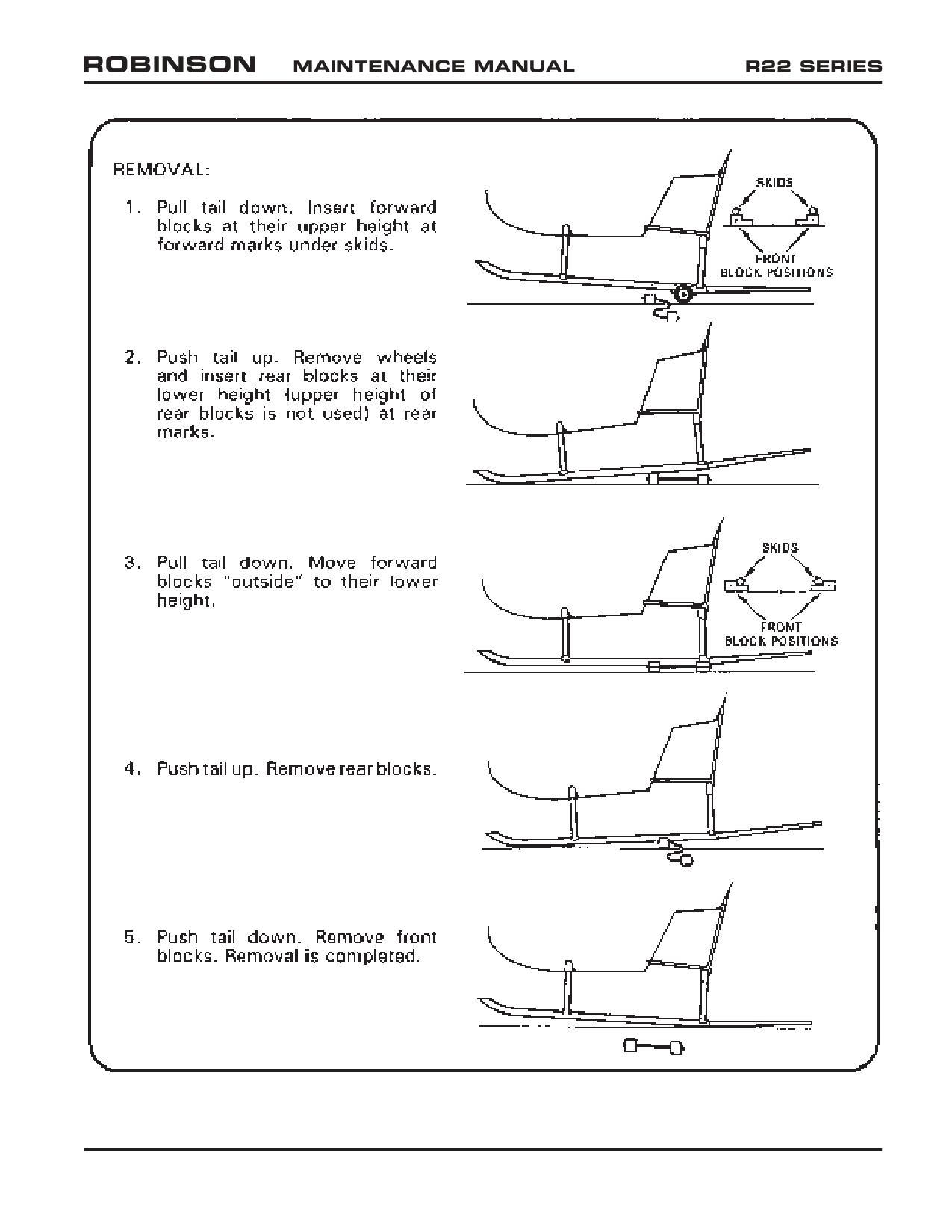
FIGURE 19-3 FLOAT LANDING GEAR GROUND HANDLING WHEELS REMOVAL
OCT 2018
Chapter 19 Ground Handling
Page 19.5
19-12 Moving Helicopter on Ground Handling Wheels
1. Position main rotor blades approximately fore and aft and apply rotor brake.
2. Install ground handling wheels per § 19-11.
3. Verify ground handling area is free of foreign object debris.
4. Have one person pull down on tail rotor gearbox until skid tubes are parallel with the
ground. During ground handling, balance helicopter to minimize wear on forward skid
shoes and rear extensions.
NOTE
Steer helicopter by gripping the tail rotor gearbox, aft tailcone
section, or inboard part of horizontal stabilizer between tailcone
and vertical stabilizers.
CAUTION
Do not steer helicopter by gripping the tail rotor guard, vertical
stabilizers, outboard part of horizontal stabilizer, tail rotor, tail
rotor controls, or tail skid.
5. If additional help is needed, a second person may push on one of the aft vertical frame
tubes or on the nose.
19-13 Ground Handling Carts
The R22 can be handled by one person using the MT900-1 or MT950-1 ground handling cart.
MT900 and MT950 Operating Instructions, Maintenance Manuals, and Illustrated Parts
Catalogs are available online at www.robinsonheli.com.
Page 19.6
Chapter 19 Ground Handling
OCT 2018
19-20 Trailering
CAUTION
Trailering the R22 is not normally recommended. Most trailers
large enough to accommodate the helicopter are designed for
much heavier loads; the trailer’s springs and shock absorbers
will not function properly when lightly-loaded. Also, without
support, the tailcone can resonate with trailer vibrations,
subjecting the tailcone to greatly amplified loads.
If trailering is unavoidable, observe the following precautions:
1. Load trailer with ballast to an average weight the trailer is designed to carry.
2. Support the tailcone. Cushion support point(s) to prevent tailcone damage.
3. Perform one of the following options:
a. Remove main rotor blades per § 26-10. Pack blades in shipping crate.
b. Fabricate blade supports to unload droop stops. Position supports approximately
five feet from blade tips. Cushion support points to prevent blade damage.
4. Restrain tail rotor to prevent teetering.
5. Fuel helicopter per § 22-51.
6. Protect windshield, windows, rotor systems, and all fragile equipment from exposure
to highway debris and subsequent damage.
7. After trailering, perform 100-hour maintenance and inspection per § 2.400.
OCT 2018
Chapter 19 Ground Handling
Page 19.7
Intentionally Blank
Page 19.8
Chapter 19 Ground Handling
OCT 2018
CHAPTER 20
PARKING AND STORAGE
Section Title
Page
20-10
Parking
20.1
20-11
Parking in High Wind or Turbulent Air
20.1
20-12
Main Rotor Blade Tie-Downs
20.3
20-13
Main Rotor Blade Supports
20.4
20-20
Storage (Greater than 30 Days)
20.4
OCT 2018
Chapter 20 Parking and Storage
Page 20.i
Intentionally Blank
Page 20.ii
Chapter 20 Parking and Storage
OCT 2018
CHAPTER 20
PARKING AND STORAGE
20-10 Parking
1. Place cyclic control in neutral and apply friction.
2. Put collective full down and apply friction.
3. Align rotor blades approximately fore and aft. Apply rotor brake. Install main rotor
blade tie-down(s) in windy conditions per § 20-12.
CAUTION
Do not pull down on blades to teeter rotor. To lower a blade,
push up on opposite blade.
4. During storm conditions, helicopter should be hangared or moved to a safe area (refer
to § 20-11).
20-11 Parking in High Wind or Turbulent Air
A. High Wind or Turbulent Air
Helicopter should be hangared or moved to a safe area during storm conditions or
when storm conditions are forecasted. When parking helicopter in high winds or
when aircraft is exposed to prop/rotor wash or jet blast:
1. Position helicopter with nose pointed in the direction of prevailing wind or
turbulent air.
2. Park helicopter per § 20-10. Position rotor blades slightly offset from fore and
aft to prevent aft blade from flapping into tailcone, and apply rotor brake.
3. If helicopter is hangared, turn fuel shutoff valve off.
OCT 2018
Chapter 20 Parking and Storage
Page 20.1
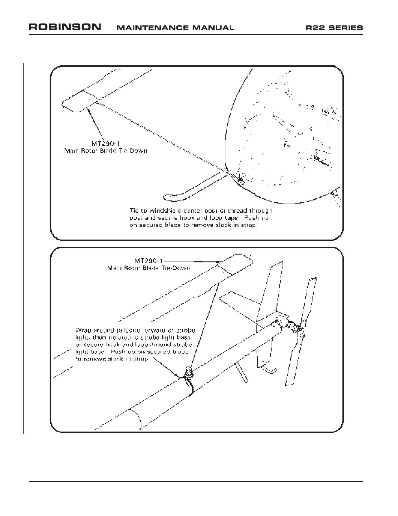
FIGURE 20-1 MAIN ROTOR BLADE TIE-DOWNS
Page 20.2
Chapter 20 Parking and Storage
OCT 2018
20-11 Parking in High Wind or Turbulent Air (continued)
B. Extreme Conditions
In extreme conditions, at the operator’s discretion:
1. Remove main rotor blades per § 26-10. Remove tail rotor assembly per § 9.210.
Store main rotor blades and tail rotor assembly in hangar or safe area.
2. Remove main rotor pitch links per steps below, or temporarily secure links
together using ty-rap(s) or safety wire:
a. Mark an “X” on one pitch link lower rod end and corresponding swashplate
ear using a colored grease pencil. Mark an “O” on opposite link and
corresponding swashplate ear.
b. Remove hardware securing pitch links to swashplate assembly.
3. Remove tail rotor pitch links per steps below:
a. Refer to Figure 9-11. Tag each pitch link with corresponding blade serial
number. Disconnect pitch links from tail rotor blades; keep associate
balancing hardware with each link.
b. Remove hardware securing pitch links to tail rotor pitch control assembly.
20-12 Main Rotor Blade Tie-Downs
CAUTION
Overtightening tie-down straps can damage main rotor blades.
Maximum tie-down tension is 5 lb.
1. Park helicopter per § 20-10.
2. Refer to Figure 20-1. Slide MT290-1 tie-down jacket over forward (lowered) main
rotor blade tip, white lettering facing down. Tie strap to windshield center post or
thread strap through post and secure hook and loop tape. Push up on secured blade
to remove slack in tie-down strap.
3. As required, install MT290-1 tie-down on aft main rotor blade. Slide jacket over
blade tip, white lettering facing down. Wrap strap around tailcone forward of strobe
light, then tie around strobe light base or secure hook and loop tape around strobe
light base. Push up on secured blade to remove slack in tie-down strap.
OCT 2018
Chapter 20 Parking and Storage
Page 20.3
20-13 Main Rotor Blade Supports
Reserved.
20-20 Storage (Greater than 30 days)
1.
Record the date helicopter is prepared and placed in storage.
CAUTION
To minimize risk of electrical discharge: when disconnecting
battery, disconnect negative (ground) cable from battery first,
then the positive cable. When connecting battery, connect
positive cable to battery first, then the negative (ground) cable.
2.
Turn battery off. Remove cotter rings and wing nuts securing battery box cover to box
and remove cover. Remove hardware securing cables to battery. Remove battery.
Inspect and service battery according to battery manufacturer’s instructions.
3.
Preserve engine for storage per Lycoming Service Letter no. L180 (current revision).
4.
Fill main and tail gearboxes to center of sight glass with A257-2 oil.
5.
Fuel helicopter per R22 Pilot’s Operating Handbook (POH) Section 8.
NOTE
Fuel lubricates bladder inner liner and keeps it from drying out
or cracking. Refuel helicopter after run-ups during storage.
6.
Clean aircraft per POH Section 8. Verify helicopter is completely dry.
7.
Refinish main rotor blades per § 26-10. Refinish tail rotor blades per § 9.220. If blade
painting is not feasible, wax blades.
8.
Position helicopter in a hangar or protected environment.
9.
Apply suitable non-drying corrosion preventive compound to A166 clutch shaft adjacent
to seals (where shaft enters and exits upper sheave).
10.
Open door vents or remove doors to ventilate cabin as required.
11.
Close and latch access doors.
NOTE
During storage, periodically inspect helicopter for corrosion;
helicopters stored in humid environments will require more
frequent inspection.
Page 20.4
Chapter 20 Parking and Storage
OCT 2018
CHAPTER 21
PLACARDS AND MARKINGS
Page
Section Title
21-10
Placards and Markings
21.1
OCT 2018
Chapter 21 Placards and Markings
Page 21.i
Intentionally Blank
Page 21.ii
Chapter 21 Placards and Markings
OCT 2018
CHAPTER 21
PLACARDS AND MARKINGS
21-10 Placards and Markings
Refer to R22 Illustrated Parts Catalog Chapter 11 for placard and marking locations.
A. Removal
To remove previously installed decals, start at corners and slowly peel off decal by
hand or using a plastic wedge. Avoid damaging or removing paint or primer from
surfaces. Remove decal entirely.
B. Installation
Verify surfaces are clean and dry before attaching decals. Use a clean cloth wet
with acetone or mild soapy water to clean surfaces, but use caution when using
acetone near silk-screened lettering on console and circuit breaker panel. Acetone
can smudge or remove silk-screened letters. Attach decal and rub decal surface with
finger, applying slight pressure.
OCT 2018
Chapter 21 Placards and Markings
Page 21.1
Intentionally Blank
Page 21.2
Chapter 21 Placards and Markings
OCT 2018
CHAPTER 22
SERVICING
Section Title
Page
22-10
Main Rotor Gearbox
22.1
22-11
Cleaning Chip Detector
22.3
22-12
Cleaning Sight Gage
22.3
22-13
Main Rotor Gearbox Drain and Flush
22.4
22-20
Tail Rotor Gearbox
22.5
22-21
Cleaning Chip Detector
22.6
22-22
Cleaning Sight Gage
22.6
22-23
Tail Rotor Gearbox Drain and Flush
22.7
22-30
Clutch Assembly Lubricant Inspection and Servicing
22.8
22-40
Clutch Actuator Upper and Lower Bearings
22.9
22-41
Upper Bearing Lubrication
22.9
22-42
Lower Bearing Lubrication
22.10
22-50
Fuel System
22.11
22-51
Fueling
22.11
22-52
Defueling
22.11
22-60
Main Rotor Blades
22.13
22-61
Pitch Bearing Housing
22.13
OCT 2018
Chapter 22 Servicing
Page 22.i
Intentionally Blank
Page 22.ii
Chapter 22 Servicing
OCT 2018
CHAPTER 22
SERVICING
22-10 Main Rotor Gearbox
NOTE
Inspect main rotor gearbox for leaks when “top off” is required.
NOTE
Verify aircraft is on level ground when evaluating gearbox oil
level.
WARNING
Refer to Safety Data Sheets (SDS) and observe precautions
when working in proximity to hazardous materials.
A. Draining Oil
1. Run-up helicopter for approximately five minutes at 70-75% RPM per R22 Pilot’s
Operating Handbook (POH) Section 4 as required to warm oil and expedite draining.
2. Disconnect chip detector wiring from airframe harness at connectors. Remove
chip detector from housing.
3. Refer to Figure 22-1. Insert MT054-1 drain assembly (or MT053-1 drain assembly
for threaded chip detector) into housing. Position drain hose overboard into a
suitable drain container. Jam wedge between firewall and drain assembly to
open valve and drain oil. Remove drain assembly after oil has drained.
B. Adding Oil
1. Install chip detector in housing, if removed. (Special torque threaded chip detector
per § 23-33.) Connect chip detector wiring to airframe harness at connectors.
2. Remove gearbox filler-plug. Fill gearbox to center of sight glass using A257-2 oil.
Rotate rotor system by hand for several revolutions and pull down on tail rotor
gearbox several times. Check gearbox oil level and adjust as required. Install
gearbox filler-plug and special torque plug per § 23-33.
3. Run-up helicopter approximately five minutes at 70-75% RPM per R22 Pilot’s
Operating Handbook (POH) Section 4.
4. Check gearbox oil level, and adjust as required.
OCT 2018
Chapter 22 Servicing
Page 22.1
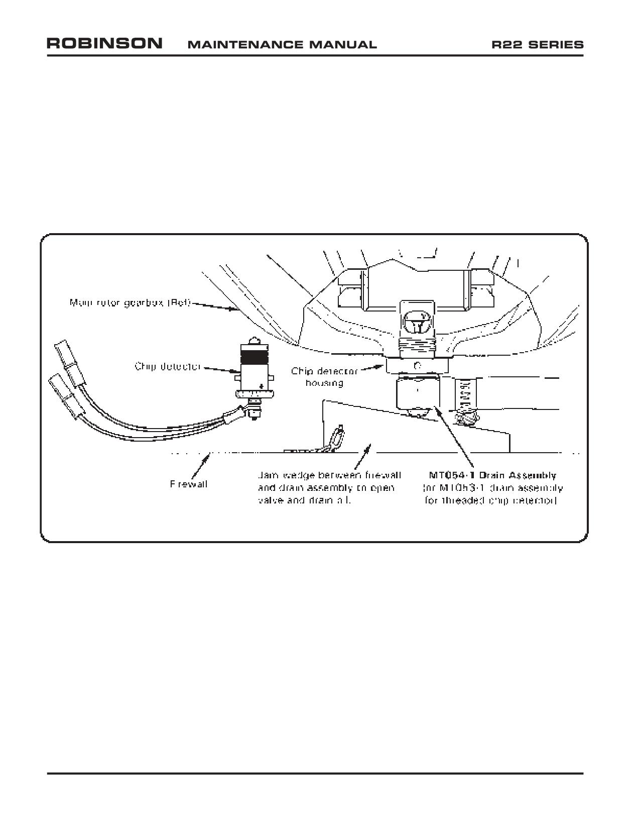
FIGURE 22-1 DRAINING MAIN ROTOR GEARBOX
Page 22.2
Chapter 22 Servicing
OCT 2018
22-11 Cleaning Chip Detector and Chip Detector Housing
WARNING
Refer to Safety Data Sheets (SDS) and observe precautions
when working in proximity to hazardous materials.
1. Disconnect chip detector wiring from airframe harness at connectors. For tail gearbox
chip detector, place suitable drain container below gearbox. Remove chip detector
from housing or gearbox.
2. Clean chip detector using a toothbrush and approved solvent (refer to § 23-70).
Remove debris using compressed air or masking tape; do not use a magnet. Dry chip
detector using compressed air or a lint-free cloth. Inspect condition.
3. Connect chip detector wiring to airframe harness at connectors. Turn battery on.
Touch detector’s magnet to airframe and verify appropriate gearbox caution light
illuminates. Turn battery off. Disconnect chip detector wiring from airframe harness
at connectors.
4. Install chip detector in housing or gearbox. Special torque threaded chip detector per
§ 23-33. Connect chip detector wiring to airframe harness at connectors.
5. Turn battery on. Depress push-to-test button(s) and verify appropriate gearbox caution
light illuminates. Turn battery off.
6. As required, remove filler-plug. Fill gearbox to center of sight glass using A257-2 oil.
Rotate rotor system by hand for several revolutions and pull down on tail rotor gearbox
several times. Check gearbox oil level and adjust as required. Install filler-plug in
gearbox and special torque plug per § 23-33.
22-12 Cleaning Sight Gage
1. Drain main rotor gearbox oil per § 22-10.
2. Remove sight gage from gearbox.
3. Clean sight glass using a toothbrush and approved solvent (refer to § 23-70). Dry
sight gage using compressed air or a lint-free cloth. Inspect condition.
4. Install sight gage in gearbox and special torque gage per § 23-33. Verify security.
OCT 2018
Chapter 22 Servicing
Page 22.3
22-13 Main Rotor Gearbox Drain And Flush
WARNING
Refer to Safety Data Sheets (SDS) and observe precautions
when working in proximity to hazardous materials.
1.
Run-up helicopter for approximately five minutes at 70-75% RPM per R22 Pilot’s
Operating Handbook (POH) Section 4 as required to warm oil and expedite draining.
2.
Disconnect chip detector wiring from airframe harness at connectors. Remove chip
detector from housing.
3.
Refer to Figure 22-1. Insert MT054-1 drain assembly (or MT053-1 drain assembly
for threaded chip detector) into housing. Position drain hose overboard into a suitable
drain container. Jam wedge between firewall and drain assembly to open valve and
drain oil.
4.
Remove drain assembly after oil has drained. Install chip detector (special torque
threaded chip detector per § 23-33). Connect chip detector wiring to airframe harness
at connectors.
5.
Remove filler-plug. Fill gearbox to center of sight glass using SAE30, SAE40, SAE50,
or SAE20W50 mineral oil. Install filler-plug and special torque plug per § 23-33.
6.
Run-up helicopter for approximately five minutes at 70-75% RPM per POH Section 4.
7.
After shutdown, drain mineral oil per steps 2 thru 4. Remove drain assembly after oil
has drained.
8.
Remove chip detector housing. Clean chip detector and housing using a toothbrush
and approved solvent (refer to § 23-70). Remove debris using compressed air or
masking tape; do not use a magnet. Dry chip detector and housing using compressed
air or a lint-free cloth. Inspect condition.
9.
Connect chip detector wiring to airframe harness at connectors. Turn battery on.
Touch detector’s magnet to firewall and verify MR CHIP caution light illuminates. Turn
battery off. Disconnect chip detector wiring from airframe harness at connectors.
10.
Install chip detector housing in gearbox and special torque housing per § 23-33.
Install chip detector in housing. (Special torque threaded chip detector per § 23-33.)
Connect chip detector wiring to airframe harness at connectors.
11.
As required, remove sight gage and clean glass using approved solvent (refer to
§ 23-70). Install sight gage and special torque gage per § 23-33.
12.
Remove filler-plug. Fill gearbox to center of sight glass using A257-2 oil. Rotate rotor
system by hand for several revolutions and pull down on tail rotor gearbox several
times. Check gearbox oil level and adjust as required. Install filler-plug in gearbox and
special torque plug per § 23-33.
13.
Turn battery on. Depress push-to-test MR CHIP button and verify caution light
illuminates. Turn battery off.
Page 22.4
Chapter 22 Servicing
OCT 2018
22-20 Tail Rotor Gearbox
NOTE
Inspect tail rotor gearbox for leaks when “top off” is required.
NOTE
Verify aircraft is on level ground when evaluating gearbox oil
level.
WARNING
Refer to Safety Data Sheets (SDS) and observe precautions
when working in proximity to hazardous materials.
A. Draining Oil
1. Cut and discard ty-raps as required and disconnect chip detector wiring from
airframe harness at connectors.
2. Place a suitable drain container under tail rotor gearbox to catch oil, then remove
chip detector.
B. Adding Oil
1. Install chip detector in tail gearbox and special torque detector per § 23-33.
2. Connect chip detector wiring and install ty-raps, as required. Cinch ty-raps until
snug without over-tightening, and trim tips flush with heads.
3. Turn battery switch on. Verify TR CHIP caution light illuminates when test button
is depressed. Turn battery switch off.
4. Remove gearbox filler-vent plug and fill gearbox with A257-22 lubricant to center
of sight glass. Rotate rotor system by hand for several revolutions and pull down
on tail rotor gearbox several times. Check gearbox oil level and adjust as required.
5. Install filler-vent plug in gearbox and special torque plug per § 23-33.
OCT 2018
Chapter 22 Servicing
Page 22.5
22-21 Cleaning Chip Detector
1. Drain tail rotor gearbox oil per § 22-20.
2. Clean chip detector using a toothbrush and approved solvent (refer to § 23-70).
Remove debris using compressed air or masking tape; do not use a magnet. Dry chip
detector using compressed air or a lint-free cloth. Inspect condition.
3. Connect chip detector wiring to airframe harness at connectors. Turn battery switch
on. Touch detector’s magnet to airframe and verify TR CHIP caution light illuminates.
Turn battery switch off. Disconnect chip detector wiring from airframe harness at
connectors.
4. Install chip detector in gearbox and special torque detector per § 23-33. Connect chip
detector wiring to airframe harness at connectors. Verify security.
5. Turn battery switch on. Depress push-to-test button and verify TR CHIP caution light
illuminates. Turn battery switch off.
12-22 Cleaning Sight Gage
1. Drain tail rotor gearbox oil per § 22-20.
2. Remove sight gage from gearbox.
3. Clean sight gage using a toothbrush and approved solvent (refer to § 23-70). Dry
sight gage using compressed air or a lint-free cloth. Inspect condition.
4. Install sight gage in gearbox and special torque gage per § 23-33. Verify security.
Page 22.6
Chapter 22 Servicing
OCT 2018
22-23 Tail Rotor Gearbox Drain And Flush
WARNING
Refer to Safety Data Sheets (SDS) and observe precautions
when working in proximity to hazardous materials.
1.
Run-up helicopter for approximately five minutes at 70-75% RPM per R22 Pilot’s
Operating Handbook (POH) Section 4 as required to warm oil and expedite draining.
2.
Disconnect chip detector wiring from airframe harness at connectors. Place a suitable
drain container below tail rotor gearbox and remove chip detector.
3.
Remove filler-plug. Fill gearbox to center of sight gage using SAE30, SAE40, SAE50,
or SAE20W50 mineral oil. Install filler-plug and special torque plug per § 23-33.
4.
Run-up helicopter for approximately five minutes at 70-75% RPM per POH Section 4.
5.
After shutdown, drain mineral oil per step 2.
6.
Clean chip detector using a toothbrush and approved solvent (refer to § 23-70).
Remove debris using compressed air or masking tape; do not use a magnet. Dry chip
detector and housing using compressed air or a lint-free cloth. Inspect condition.
7.
Connect chip detector wiring to airframe harness at connectors. Turn battery on.
Touch detector’s magnet to airframe and verify TR CHIP caution light illuminates. Turn
battery off. Disconnect chip detector wiring from airframe harness at connectors.
8.
Install chip detector in gearbox and special torque detector per § 23-33. Connect chip
detector wiring to airframe harness at connectors.
9.
As required, remove sight gage and clean glass using approved solvent (refer to
§ 23-70). Install sight gage and special torque gage per § 23-33.
10.
Remove filler-plug. Fill gearbox to center of sight gage using A257-2 oil. Rotate rotor
system by hand for several revolutions and pull down on tail rotor gearbox several
times. Check gearbox oil level and adjust as required. Install filler-plug in gearbox and
special torque plug per § 23-33.
11.
Turn battery on. Depress push-to-test TR CHIP button and verify caution light
illuminates. Turn battery off.
OCT 2018
Chapter 22 Servicing
Page 22.7
22-30 Clutch Assembly Lubricant Inspection and Servicing
A. Clutch Assemblies with A168-4 (Forward) Retainer
WARNING
Avoid contaminating drive belts and sheaves with lubricant.
Clean contaminated surfaces with mild soap and water solution,
followed by a warm water rinse. Place a clean, absorbent rag
beneath MT147-2 fittings, when installed, to catch any drips.
1.
Open main rotor gearbox compartment access doors.
2.
Rotate clutch shaft until bolts securing yokes to shaft are vertical. Engage rotor
brake.
3.
Remove A168-4 (forward) retainer’s top B289-3 screw and install clean MT147-2
fitting. Attach drain hose.
4.
Rotate sheave until fitting and attached drain hose are on bottom. Route drain hose
into a suitable, clean container. Remove top B289-3 screw and allow lubricant to
drain into container.
5.
Install second clean MT147-2 fitting at top of retainer and connect a clean supply
of A257-4 lubricant to fitting. Flush sprag clutch housing until exiting lubricant is
obviously red. Disconnect lubricant supply and allow lubricant to drain completely
into container.
6.
Strain all lubricant from container through a 180-200 micron paint filter/strainer.
Fluid may be dark, and may sparkle with very fine metallic debris; this is normal. If
metallic debris is trapped in the filter/strainer, remove clutch assembly and return
it to RHC, or an R22 Service Center authorized to overhaul clutch assemblies, for
disassembly and inspection.
7.
If metallic debris is not found in the filter, attach drain hose to top fitting. Route
drain hose into a suitable container. Connect a clean supply of A257-4 lubricant
to bottom fitting. Fill sprag clutch housing thru bottom fitting until no air bubbles
are visible in drain hose. Shut-off fluid flow.
8.
Remove top fitting and install screw. Rotate sheave until opposite fitting is on
top. Remove fitting and verify lubricant level contacts threads; add lubricant as
required. Install forward screw.
9.
Close main rotor gearbox compartment access doors.
B. Clutch Assemblies with Retainer without B289-3 Screws
1. Perform clutch assembly (aft) seal replacement per § 7.213.
Page 22.8
Chapter 22 Servicing
OCT 2018
22-40 Clutch Actuator Upper and Lower Bearings
The actuator upper bearing is located on the clutch shaft, and the actuator lower bearing is
located on the fanshaft. Failure of either actuator bearing in flight could cause loss of power
to rotor system and result in a serious accident. Refer to § 2.110 for general indications
of bearing failure. In addition, just before failure of an actuator bearing, clutch light may
flicker (on and off in less than one second) constantly or illuminate for a longer time than
usual. Do not be confused with normal retensioning in flight (light on for up to 8 seconds,
then off). Flight should not be resumed until cause of abnormal clutch light illumination has
been determined.
Perform the following bearing inspections whenever an actuator bearing discrepancy is
suspected or fanwheel is removed:
22-41 Upper Bearing Lubrication
WARNING
Refer to Safety Data Sheets (SDS) and observe precautions
when working in proximity to hazardous materials.
NOTE
Kl-115 Special Tools Kit (syringe and probe) required to perform
the following procedure.
1. Fill syringe with 2-3 grams A257-12 grease (refer to § 23-70). Note: 2.5 grams of
grease fills a 0.5 inch (13 mm) long space inside a syringe body with a 0.63 inch (16
mm) inner diameter.
2. Thoroughly clean an accessible portion of A184 bearing assembly aft rubber seal and
surrounding surface.
3. Gently press plastic tip of syringe against cleaned seal inner lip until lip deflects inward
and tip slips into bearing. Do not damage seal. Inject grease with syringe perpendicular
to seal. Withdraw syringe. Part of seal’s inner lip remains deflected inward.
4. Slide tip of steel probe under seal inner lip and return deflected portion of lip to original
position. Do not damage seal.
5. Run-up helicopter for approximately two minutes 104% RPM per R22 Pilot’s Operating
Handbook (POH) Section 4. Shut down, inspect bearing, and clean off any escaped grease.
WARNING
Bearing used in A184 bearing assembly has modified internal
clearance for use on R22. Do not substitute any other bearing.
OCT 2018
Chapter 22 Servicing
Page 22.9
22-42 Lower Bearing Lubrication
WARNING
A181-1 & A181-3 bearings are obsolete and must be removed
from service.
1.
Remove fanwheel per § 6.210.
2.
Disconnect lower end of belt tension actuator from bearing housing.
3.
Rotate bearing housing. Verify no roughness, scraping, or excessive looseness (0.010
inch maximum axial play). Verify no seal damage, and no heat damage. Lubricate
bearing:
a. Remove four perimeter screws, nuts, and washers.
b. Remove bearing block with attached outer race (bearing outer race is split type).
Forward seal retainer, forward seal, bearing inner race and bearing rollers will
remain on fan shaft.
c. Clean parts, including seals, and inspect for obvious damage.
d. Lubricate bearing by filling openings on both sides of roller cage with A257-12
grease, but do not fill spaces between rollers.
e. Reassemble. Ensure forward seal fits properly into recess provided in forward
seal retainer (not applicable to Rev L bearings).
f. Standard torque MS24694-S61 screws per § 23-32.
g. Rotate bearing housing. Verify no roughness and no excessive looseness.
4.
Inspect bearing inner race on fanshaft. No movement or fretting is allowed between
inner race and fanshaft.
5.
If any indication of bearing failure is found, replace A007-3 or -5 shaft and bearing
assembly per § 7.290.
6.
Install fanwheel per § 6.220.
7.
If bearing was lubricated, inspect & clean off any escaped grease after balancing
fanwheel.
Page 22.10
Chapter 22 Servicing
OCT 2018
22-50 Fuel System
WARNING
Refer to Safety Data Sheets (SDS) and observe precautions
when working in proximity to hazardous materials.
WARNING
Always fuel or defuel helicopter in a well-ventilated area. No
smoking within 100 feet of aircraft during fueling.
22-51 Fueling
1. Turn battery switch off.
2. Ground helicopter and ground fuel vehicle. Ground fuel vehicle to helicopter.
3. Verify proper grade of aviation fuel. See R22 Pilot's Operating Handbook (POH)
Section 2 for approved fuel grades and instructions for use of anti-ice additive.
NOTE
Refer to Figure 2-4A. Verify A689-6 fuel cap is revision J or
subseqent if bladder tanks are installed (revision J or subsequent
caps may also be used on all-aluminum tanks).
4. Remove fuel cap(s) and fuel helicopter as required.
5. Install fuel cap(s); verify security.
6. Remove grounding equipment.
22-52 Defueling
1. Turn battery switch and fuel valve off.
2. Place suitable drain container beneath carburetor and ground container to helicopter.
3. Disconnect fuel hose assembly from carburetor.
4. Turn fuel valve on to drain fuel. (Perform low-fuel switch operation check per § 12.430,
if desired.)
5. Connect fuel hose assembly to carburetor, special torque hose assembly nut per
§ 23-33, and torque stripe per Figure 2-1.
OCT 2018
Chapter 22 Servicing
Page 22.11
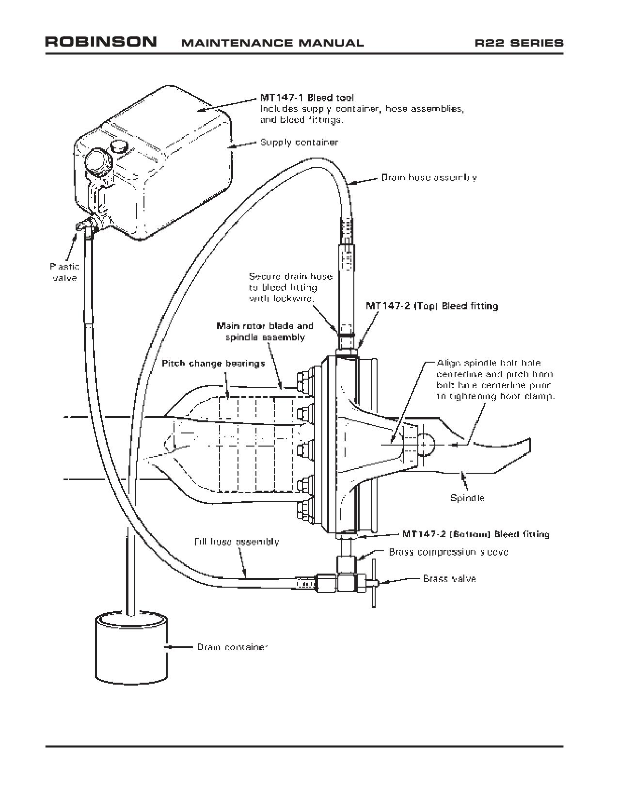
FIGURE 22-2 FILLING PITCH BEARING HOUSING
Page 22.12
Chapter 22 Servicing
OCT 2018
22-60 Main Rotor Blades
22-61 Pitch Bearing Housing
NOTE
MT147-1 Main rotor blade spindle air bleed tool includes supply
container, hose assemblies, and bleed fittings.
WARNING
Refer to Safety Data Sheets (SDS) and observe precautions
when working in proximity to hazardous materials.
1.
Remove main rotor blades per § 26-10.
2.
Refer to Figure 22-2. Place a suitable drain container below main rotor pitch horn.
Remove two B289-2 bolts from pitch horn and drain fluid.
3.
Install MT147-2 bleed fittings into pitch horn openings. Attach drain hose assembly
to (top) bleed fitting, secure with two wraps of lockwire. Position drain hose into drain
container.
4.
Place supply container with sufficient A257-4 fluid approximately 3 feet above spindle.
Route fill hose assembly into drain container and open brass valve. Open supply
container plastic valve and purge air from fill hose. Close valves.
5.
Connect brass valve to (bottom) bleed fitting by tightening brass compression sleeve.
6.
Open valves and fill spindle housing until no air bubbles are visible in drain hose
assembly. Massage spindle boot, oscillate spindle, and raise blade tip up & down to
remove trapped air.
7.
Remove drain hose assembly and (top) bleed fitting, and install B289-2 bolt. Roll the
blade over. After five minutes, inspect the boot for leaks. If no leaks are found, close
valves, remove fill hose assembly brass valve and (bottom) bleed fitting, and install
other bolt.
8.
Special torque B289-2 bolts per § 23-33 and torque stripe per Figure 2-1.
9.
Repeat steps for opposite blade.
OCT 2018
Chapter 22 Servicing
Page 22.13
Intentionally Blank
Page 22.14
Chapter 22 Servicing
OCT 2018
CHAPTER 23
STANDARD PRACTICES
Section Title
Page
23-10
Cleaning
23.1
23-20
Lubrication
23.3
23-30
Torque Requirements
23.5
23-31
Torque Stripe
23.7
23-32
Standard Torques
23.8
23-33
Special Torques
23.9
23-34
D210-series Nuts on Critical Fasteners
23.13
23-40
Non-Destructive Testing
23.14
23-41
Magnetic Particle Inspection
23.14
23-42
Fluorescent Penetrant Inspection
23.15
23-50
Corrosion Control
23.15
23-60
Priming and Painting
23.16
23-70
Approved Materials
23.19
23-71
Paint Strippers
23.19
23-72
Solvents and Cleaners
23.19
23-73
Fillers and Putty
23.20
23-74
Torque Seal
23.20
23-75
Primers
23.21
23-76
Powder Coat
23.21
23-77
Paints
23.22
23-78
Lubricants
23.25
23-79
Adhesives and Sealants
23.26
23-80
Miscellaneous Practices
23.28
23-81
Part Interchangeability
23.28
23-82
Thermal Fitting Parts
23.28
23-83
Replacement Component Identification (Data) Plates
23.28
23-84
Crimp Inspection
23.29
23-85
Storage Limits
23.30
23-86
B526 Screws and B527-08 Washers
23.30
OCT 2018
Chapter 23 Standard Practices
Page 23.i
Intentionally Blank
Page 23.ii
Chapter 23 Standard Practices
OCT 2018
CHAPTER 23
STANDARD PRACTICES
23-10 Cleaning
CAUTION
Wash helicopter exterior surfaces, windshields, and windows
with mild soap and water. Harsh abrasives, alkaline soaps, or
detergents can scratch painted or plastic surfaces, or cause
corrosion of metal. Protect areas where cleaning solution could
cause damage.
CAUTION
Never use high-pressure spray to clean helicopter. Never blow
compressed air into main or tail rotor blade tip drain holes, pitot
tube, or static ports.
WARNING
Refer to Safety Data Sheet (SDS) and observe precautions
when working in proximity to hazardous materials.
A. Cleaning Exterior Surfaces
1. Rinse away loose dirt and debris from exterior surface with clean water.
2. Apply mild soap and clean warm water solution to exterior surface using a clean,
soft cloth, sponge, or soft bristle brush. Use caution near antennas and sensitive
equipment.
3. Remove oil and grease using a cloth wetted with aliphatic naphtha.
4. Rinse all surfaces thoroughly.
5. If desired, polish painted surfaces with a good quality automotive wax using soft
cleaning cloths, or a chamois cloth, free of abrasive debris.
OCT 2018
Chapter 23 Standard Practices
Page 23.1
23-10 Cleaning (continued)
B. Cleaning Windshield and Windows
CAUTION
Do not use gasoline, other alcohols, benzene, carbon tetrachlo-
ride, thinner, acetone, or window (glass) cleaning sprays.
1. Rinse away loose dirt and debris from windshield and windows with clean water.
2. Apply mild soap and clean warm water solution, or aircraft plastic cleaner, to
windshield and windows using a clean, soft cloth or sponge in a straight back and
forth motion. Do not rub harshly.
3. Remove oil and grease using a cloth wetted with isopropyl alcohol (rubbing alcohol)
or aliphatic naphtha.
4. After cleaning plastic surfaces, apply a thin coat of hard polishing wax. Rub lightly
with a soft cloth. Do not use a circular motion.
5. To remove scratches, rub windshield or windows with jeweler’s rouge then hand
polish with commercial plastic polish. Polish in figure eight motion.
C. Cleaning Seat Assemblies and Back Rests
1. Vacuum and brush, then wipe with damp cloth. Dry immediately.
2. Soiled upholstery, except leather, may be cleaned with a good upholstery cleaner
suitable for the material. Follow manufacturer’s instructions. Avoid soaking or
harsh rubbing.
3. Leather should be cleaned with saddle soap or a mild hard soap and water.
D. Cleaning Carpet
Remove loose dirt with a whisk broom or vacuum. For soiled spots and stains, use
nonflammable dry cleaning liquid.
Page 23.2
Chapter 23 Standard Practices
OCT 2018
23-20 Lubrication
WARNING
Refer to Safety Data Sheets (SDS) and observe precautions
when working in proximity to hazardous materials.
Most bearings are sealed or self-lubricated and do not require periodic lubrication. Bearings
with scheduled lubrication intervals are listed in Table 1-1 (see Chapter 1).
Engine lubrication requirements are located in the R22 Pilot’s Operating Handbook, the
appropriate model Lycoming Operator’s Manual, and Lycoming Service Instruction No.
1014 (current revision).
Main and tail gearboxes require servicing when indicated by sight gage level. Additionally,
change gearbox oil and clean respective sight gage when oil becomes so dirty its level
cannot be determined.
WARNING
A257-2 oil is the only approved oil for use in gearboxes.
When installing a new or overhauled gearbox, drain and flush gearbox after the first 4
hours of flight or first chip light, whichever occurs first. Thereafter, change gearbox oil at
intervals listed in Table 1-1 (see Chapter 1).
OCT 2018
Chapter 23 Standard Practices
Page 23.3
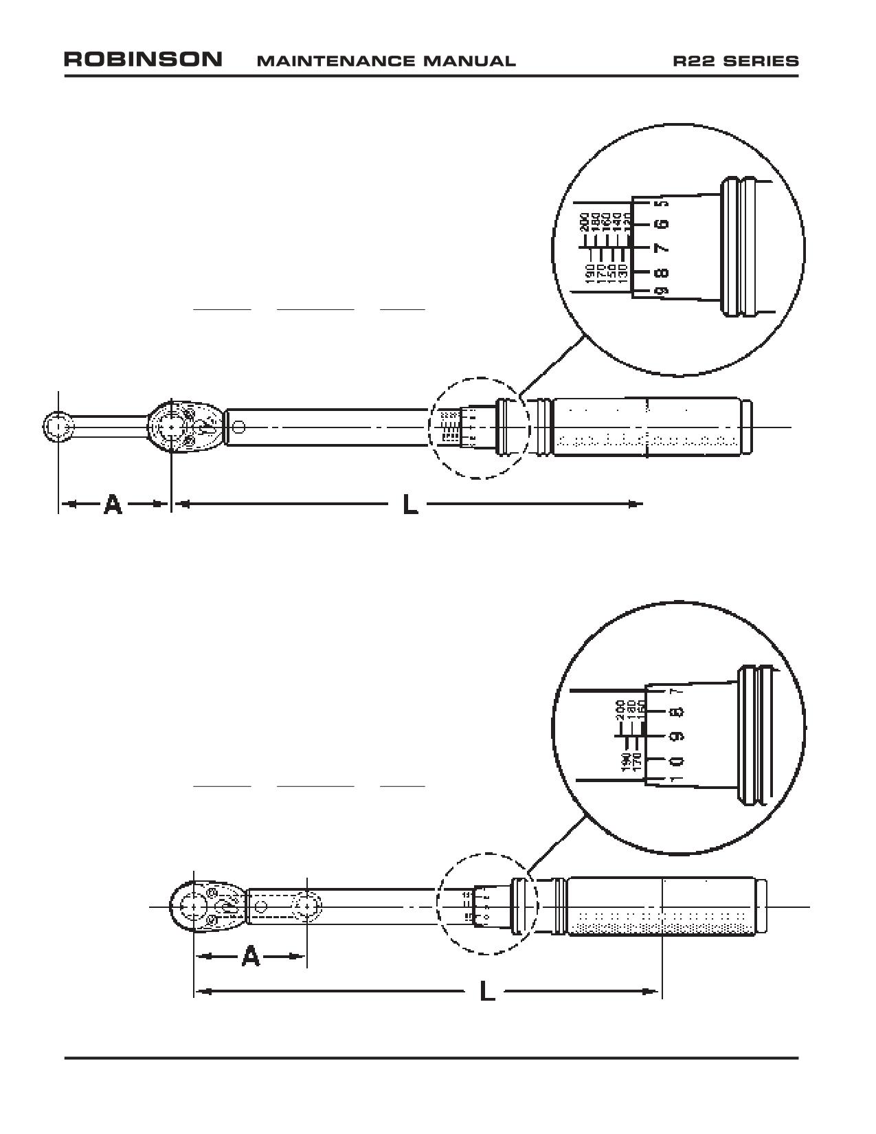
Given
Symbols
Y = Unknown
Y = Torque wrench setting
T
= 135 in.-lb
T = Torque applied to fastener
L
= 10 in.
L = Length of torque wrench
A
= 1.5 in.
A = Length of adapter
When using an adapter that lengthens torque wrench effective length,
calculate torque wrench setting using the formula below:
EXAMPLE
T x L
135 x 10
1350
Solve for Y =
=
=
= 117.39
L + A
10 + 1.5
11.5
Set torque wrench to 117 in.-lb to torque fastener to 135 in.-lb.
FIGURE 23-1 LENGTHENING TORQUE WRENCH EFFECTIVE LENGTH
Given
Symbols
Y = Unknown
Y = Torque wrench setting
T
= 135 in.-lb
T = Torque applied to fastener
L
= 10 in.
L = Length of torque wrench
A
= 1.5 in.
A = Length of adapter
When using an adapter that shortens the torque wrench effective length,
calculate torque wrench setting using the formula below:
EXAMPLE
T x L
135 x 10
1350
Solve for Y =
=
=
= 158.82
L - A
10 - 1.5
8.5
Set torque wrench to 159 in.-lb to torque fastener to 135 in.-lb.
FIGURE 23-2 SHORTENING TORQUE WRENCH EFFECTIVE LENGTH
Page 23.4
Chapter 23 Standard Practices
OCT 2018
23-30 Torque Requirements
A. Tool Calibration
Dimensions and tolerances given in this manual are critical. Calibrate measuring tools
per manufacturer’s recommendation at least once a year, when tool is dropped, misused,
or calibration is suspect. Measuring tools include torque wrenches, micrometers,
calipers, dial indicators, spring scales, protractors, and balancing equipment.
WARNING
Proper torque is critical. Always use calibrated wrenches and
undamaged, properly lubricated (where applicable) hardware.
Ensure clamping surfaces are clean, and clamp only bare metal
or wet-primed surfaces. Improper torque or dirty or painted
clamping surfaces may result in loss of clamp-up, hardware or
part damage, and premature failure.
B. Torque Value
Torque fasteners to standard dry values listed in § 23-32 unless otherwise specified.
If torque is applied by rotating bolt, increase torque value by 10% to account for
higher friction at bolt head and shank.
For example, the torque wrench setting for an NAS6605 bolt used with an MS21075
nutplate is determined as follows:
NAS6605 bolt (5 indicates 5/16 inch size) dry torque per § 23-32
240 in.-lb
Add 10% because torque must be applied at bolt head
+ 24 in.-lb
Torque wrench setting
264 in.-lb
C. Secondary Locking Mechanism
A secondary locking mechanism is required on all critical fasteners. B330 stamped
nuts (palnuts) serve as the secondary locking mechanism in most areas on the
helicopter, and are torqued per § 23-32. Palnuts must be replaced when removed.
The R22 Illustrated Parts Catalog (IPC) lists secondary locking mechanisms for specific
fasteners.
OCT 2018
Chapter 23 Standard Practices
Page 23.5
23-30 Torque Requirements (continued)
D. Critical Fastener
CAUTION
D210-series nuts, which supersede MS21042L-series and
NAS1291-series nuts, are required on critical fasteners.
WARNING
Assembly of flight controls is critical and requires inspection
by a qualified person. If a second person is not available,
RHC recommends the installer take a 5-minute break prior to
inspecting flight control connections he has assembled.
A critical fastener is one which, if removed or lost, would jeopardize safe operation
of the helicopter. This includes joints in the primary control system, and non-fail-safe
structural joints in the airframe, landing gear, and drive system.
Page 23.6
Chapter 23 Standard Practices
OCT 2018
23-30 Torque Requirements (continued)
E. Torque Requirements
CAUTION
Never substitute AN bolts for NAS bolts. NAS bolts have higher
tensile strength.
1.
Any self-locking nut whose drag has deteriorated appreciably must be replaced.
Damaged hardware must be replaced.
2.
Bolt and nut are to be clean and dry except when assembly procedure specifies
anti-seize or thread-locking compound.
3.
If chattering or jerking occurs, disassemble and re-torque fastener.
4.
If special adapters which change effective length of torque wrench are used, final
torque value must be calculated using formulas in Figures 23-1 and 23-2.
5.
Unless otherwise specified, proper thread engagement requires:
a. If palnut is not required, one to four threads exposed beyond primary nut.
b. If palnut is required, two to four threads exposed beyond primary nut.
c. For B526-8 screws, one to five threads exposed beyond primary nut.
WARNING
Proper thread engagement ensures proper locking of fastener.
Exceeding maximum thread exposure beyond primary nut
may allow nut to seat against unthreaded shank, resulting in
insufficient joint clamping.
6.
Refer to Part A. Torque wrenches must be calibrated annually, when dropped, or
when a calibration error is suspected.
23-31 Torque Stripe
WARNING
Refer to Safety Data Sheet (SDS) and observe precautions
when working in proximity to hazardous materials.
Refer to Figure 2-1. Lacquer-paint Torque Seal® is applied to all critical fasteners after
palnut installation in a stripe (“torque stripe”) extending from the fastener’s exposed
threads across both nuts and onto the component. Subsequent rotation of the nut or bolt
can be detected visually. Position torque stripes for maximum visibility during preflight
inspections. Approved Torque Seal® is listed in § 23-74.
OCT 2018
Chapter 23 Standard Practices
Page 23.7
23-32 Standard Torques
NOTE
1. Torque values are in inch-pounds unless otherwise specified.
2. Torque values include nut self-locking torque.
3. Increase torque values 10% if torqued at bolt head.
4. Wet indicates threads lubricated with A257-9 anti-seize.
5. For elbow and tee fittings which require alignment, torque to indicated
value, then tighten to desired position.
6. Tolerance is ± 10% unless range is specified.
7. Unless otherwise specified, thread sizes 8-32 and smaller are not used for
primary structure and do not require control of torques.
FASTENER SERIES
SIZE
EXAMPLE FASTENER
DRY TORQUE
10-32
NAS6603
50 in.-lb
1/4-28
NAS6604
120 in.-lb
NAS6603 thru NAS6608 Bolts
NAS1303 thru NAS1308 Bolts
5/16-24
NAS6605
240 in.-lb
NAS623 Screws
3/8-24
NAS6606
350 in.-lb
NAS1351 & NAS1352 Screws
NAS600 thru NAS606 Screws
7/16-20
NAS6607
665 in.-lb
1/2-20
NAS6608
995 in.-lb
AN3 Bolts
10-32
AN3
37 in.-lb
AN4 Bolts
AN6 Bolts
1/4-28
AN4
90 in.-lb
AN8 Bolts
AN502 & AN503 Screws
AN509 Screws
3/8-24
AN6
280 in.-lb
AN525 Screws
MS24694 Screws
1/2-20
AN8
795 in.-lb
MS27039 Screws
10-32
B330-7 (MS27151-7)
6-15 in.-lb
1/4-28
B330-13 (MS27151-13)
11-25 in.-lb
5/16-24
B330-16 (MS27151-16)
20-40 in.-lb
STAMPED NUTS
(PALNUTS)
3/8-24
B330-19 (MS27151-19)
29-60 in.-lb
7/16-20
B330-21 (MS27151-21)
42-85 in.-lb
1/2-20
B330-24 (MS27151-24)
54-110 in.-lb
1/8-27
N/A
60 in.-lb
1/4-18
N/A
85 in.-lb
TAPERED PIPE
3/8-18
N/A
110 in.-lb
THREADS
1/2-14
N/A
160 in.-lb
3/4-14
N/A
230 in.-lb
10-32
AN315-3
15 in.-lb
1/4-28
AN316-4
40 in.-lb
ROD END JAM NUTS
(AN315 and AN316)
5/16-24
AN316-5
80 in.-lb
3/8-24
AN316-6
110 in.-lb
Page 23.8
Chapter 23 Standard Practices
OCT 2018
23-33 Special Torques
These torques are non-standard and supersede those in § 23-32.
NOTE
1. Torque values are in inch-pounds unless otherwise specified.
2. Torque values include nut self-locking torque.
3. Increase torque values 10% if torqued at bolt head.
4. Wet indicates threads lubricated with A257-9 anti-seize.
5. For elbow and tee fittings which require alignment, torque to indicated
value, then tighten to desired position.
6. Tolerance is ± 10% unless range is specified.
7. Unless otherwise specified, thread sizes 8-32 and smaller are not used for
primary structure and do not require control of torques.
AREA
(QUANTITY) FASTENER
TORQUE
(1) AN320-15 nut (1½ inch socket) on A007-3 shaft assembly
183-233 ft-lb wet
DRIVE
(1) AN320-18 nut (111/16 inch socket) on A007-5 shaft assembly
340-400 ft-lb wet
SYSTEM
(6) NAS6606-24H bolts, lower sheave
300 in.-lb
EMPENNAGE
(4) NAS6603-2 & (4) NAS6603-5 bolts, vertical stabilizer attach
70 in.-lb
(1) AN320-15 or AN320-18 nut - see DRIVE SYSTEM
(8) or (12) NAS6603-3 or -6 bolts and D210-3 nuts, cone-to-
FANWHEEL
70 in.-lb
fanwheel
(6) NAS6605-12, -13, or -14 bolts, hub
300 in.-lb
(1) A457-15 bulkhead union and nut
285 in.-lb
(1) A657-1 nut, fuel valve elbow-to-bulkhead union
120 in.-lb
(1) A726-1 line assembly, bulkhead union-to-gascolator
285 in.-lb
(2) B254-3 strainer assembly, tank outlets
200 in.-lb wet
(1) B283 hose assembly nuts, gascolator-to-carburetor
120 in.-lb
(5) B289-1 bolts, fuel sender (torque in criss-cross pattern)
37 in.-lb
(2) B330-5 palnut, fuel sender ground stud
9 in.-lb
(2) B330-6 palnut, fuel sender center stud
11 in.-lb
FUEL SYSTEM
(1) D205-32 hose assembly nuts, main tank-to-fuel valve
120 in.-lb
(1) D205-33 hose assembly nuts, tank interconnect
120 in.-lb
(1) D205-34 hose assembly nuts, main tank drain
60 in.-lb
(1) D210-4 nut, gascolator mounting plug
70 in.-lb
(16) AN805 nuts, fuel primer line
20-30 in.-lb
(1) AN815-4D union, main tank, drain hose (bladder tanks)
145 in.-lb
(1) AN815-6D union, main tank, tank interconnect hose
200 in.-lb
(1) AN894D4-2 bushing, primer system
50-65 in.-lb
(1) AN894D6-4 bushing, primer system
110-130 in.-lb
OCT 2018
Chapter 23 Standard Practices
Page 23.9
23-33 Special Torques (continued)
AREA
(QUANTITY) FASTENER
TORQUE
(1) AN924-4D nut, main tank, drain valve (bladder tanks)
145 in.-lb
(1) AN924-5D nut, low-fuel warning switch
150 in.-lb
(4) MS27039C1-06 screws, fuel valve
16 in.-lb
FUEL SYSTEM
(continued)
(4) MS27039DD1-26 screws, air bypass door
22-25 in.-lb
(1) MS27769D2 plug, gascolator
60 in.-lb
Primer system line assembly nuts, flared end fittings
20-30 in.-lb
(1) B277-052 clamp, lower rib
50 in.-lb
FUSELAGE
(1) D210-5 nut, tow ball
240 in.-lb
(8) MS51861-37C screws, door hinges
36 in.-lb
(4) AN4-25A bolts, ground handling support
70 in.-lb
LANDING
GEAR
(56) NAS6604 bolts, floats to skids and skid extensions
50 in.-lb
(2 per blade) A722-4 screw, tip weight retaining
40 in.-lb wet
MAIN ROTOR
(2 per blade) B289-2 self-sealing bolts in pitch horn
70 in.-lb
BLADE
(2 per blade) NAS1351N3-10P screw, cover retaining
40 in.-lb wet
(1) AN320-8 nut, gearbox pinion
290-410 in.-lb
(1) AN10-41A bolt, gearbox mounting
90 ft-lb dry torqued from
(3) A650-1 fittings, gearbox mounting
bolt head or nut
(requires MS21044N10 nuts)
(1) F650-3 bolt, gearbox mounting
65 ft-lb, wet
(3) A650-3 fittings, gearbox mounting
torque from bolt head or nut
(requires D210-10 nuts)
MAIN ROTOR
(6) NAS1352-4-14 screws in end cover
140 in.-lb
GEARBOX
Large nut 150 in.-lb
(1) chip detector (threaded, non-quick-disconnect type)
Small nut 75 in.-lb
(1) chip detector housing
150 in.-lb
(1) nut, chip detector wiring
4-6 in.-lb
(1) filler plug
150 in.-lb
(1) sight gage
150 in.-lb
New bolt: 0.016-0.017 inch
(1) NAS630-80 (or MS21250-10080) teeter hinge bolt;
elongation (stretch), wet
(2) NAS630-80 (or MS21250-10080) coning hinge
Used bolt: 0.015-0.017
bolts in A154-1 hub
inch elongation, wet, &
MAIN ROTOR
cotter pin holes must align
HUB
New bolt: 0.011-0.012 inch
elongation (stretch), wet
(2) NAS632-82 (or MS21250-12082) coning hinge
Used bolt: 0.010-0.012
bolts in B370-1 hub
inch elongation, wet, &
cotter pin holes must align
Page 23.10
Chapter 23 Standard Practices
OCT 2018
23-33 Special Torques (continued)
AREA
(QUANTITY) FASTENER
TORQUE
OVERTRAVEL
(1) A486 screw, upper rod end
37 in.-lb
SPRING
(1) A058-5 carburetor air temp probe
36-48 in.-lb
(1) A760-1 oil temperature sender
300 in.-lb
(2) B277-024 clamps, carb heat scoop
30 in.-lb
(2) A740-1 manifold pressure line nuts
25-35 in.-lb
(4) AN818-8 nuts, oil cooler line (stainless-steel lines)
40 ft-lb
(4) AN818-8 nuts, oil cooler line (aluminum lines)
230-260 in.-lb
(1) AN894D4-3 bushing, manifold pressure line,
135-150 in.-lb
at firewall
(4) MS20074-04-04 bolts, airbox-to-carburetor
30 in.-lb
(1) 3080-00038 cylinder head temperature probe
70-80 in.-lb
(1) bolt, alternator belt tension
204 in.-lb
(4) bolts, D723-1 oil adapter
90-100 in.-lb
96 in.-lb initial, 204 in.-lb
(4) carburetor-to-engine nuts
final, torque in a crisscross
pattern
(8) exhaust riser flange nuts, plain
160-180 in.-lb
(8) exhaust riser flange nuts, self-locking
200-220 in.-lb
(2) ground strap-to-engine nuts
96 in.-lb
POWERPLANT
(1) nut, B315-1 clip for magneto harness clamp
60 in.-lb
(1) nut on A462-1 carburtetor heat control wire-to-slider
25-30 in.-lb
valve attach fitting
(1) nut on A462-4 mixture control wire-to-carburetor
25-30 in.-lb
mixture arm attach fitting
420 in.-lb wet with A257-10
(8) spark plugs
thread lubricant
(1) thermostatic oil cooler bypass valve
290-310 in.-lb
(6 per cover) NAS1352-4H10P valve cover retaining screws
25 in.-lb cold engine,
when used with clean, dry, red silicon gasket on clean,
20 in.-lb warm engine
dry valve cover and cylinder head mating surfaces
(1) terminal retaining nut, alternator output terminal (use
back-up wrench on stud retaining nut to prevent loss
50 in.-lb
of stud clamp-up)
(2) terminal retaining nuts, D748-3 alternator field and
aux terminals (use back-up wrench on stud retaining
14 in.-lb
nuts to prevent loss of stud clamp-up)
(2) terminal retaining nuts, D748-4 alternator field and
aux terminals (use back-up wrench on stud retaining
20 in.-lb
nuts to prevent loss of stud clamp-up)
(1) terminal retaining nut, oil temperature sender
20 in.-lb
OCT 2018
Chapter 23 Standard Practices
Page 23.11
23-33 Special Torques (continued)
AREA
(QUANTITY) FASTENER
TORQUE
(2) NAS1351-8H40P internal-wrenching screws
70-75 ft-lb wet
STEEL TUBE
120 in.-lb with
(3) NAS6604-3 bolts - (1) lower-left frame aft strut-to-upper
FRAME
B270-1 on shank to
frame, and (2) on removable aft, right strut
seal strut holes
(2) NAS1352N08-6 screws, magnetic pick-up bracket
35 in.-lb
(16) NAS1352N08-8 screws
35 in.-lb
SWASHPLATE
(1) NAS6605-8 bolt clamping early revision A203 yokes
190 in.-lb
(1 per link) 21FKF-616 jam nut, main rotor pitch link barrel
100 in.-lb
(1) B549-1 retainer, input seal
70 ft-lb wet
(3) MS20074-04-06 bolts, gearbox-to-tailcone mounting
100 in.-lb
(8) MS20074-04-06 bolts on A021 gearbox
60 in.-lb
(12) MS20074-04-06 bolts on B021 gearbox
100 in.-lb
(1) NAS679A4 nut, A031 pitch control housing stud
90 in.-lb
(1) NAS679A4 nut, A119-1 bumper retainer
120 in.-lb
70 ft-lb wet with
(1) D210-8 nut retaining B546 input yoke on B021 gearbox
B270-11
TAIL ROTOR
GEARBOX
(1) NAS1304-38 bolt, spherical tail rotor teeter (delta) hinge
150 in.-lb
(1) NAS6604-38 bolt, elastomeric tail rotor teeter (delta) hinge
150 in.-lb
(1) chip detector on A021 gearbox
100 in.-lb
(1) chip detector on B021 gearbox
60 in.-lb
(1) nut, chip detector wiring on B021 gearbox
4-6 in.-lb
(1) filler plug vent assembly
100 in.-lb
(1) sight gage on A021 gearbox
150 in.-lb
(1) sight gage on B021 gearbox
100 in.-lb
WINDSHIELD
(24) AN526C832R12 screws, on center outside retainer
16 in.-lb
Page 23.12
Chapter 23 Standard Practices
OCT 2018
23-34 D210-series Nuts on Critical Fasteners
When performing maintenance that involves disassembly of a critical fastener (joints with
a secondary lock), reassemble the fastener using a D210-series nut.
If a fastener is disassembled that has an MS21042L-series or NAS1291-series nut with
a B330-series palnut or B332-series lockwasher (secondary lock),
replace MS21042L08 nut or NAS1291-08 nut with D210-08 nut,
replace MS21042L3 nut or NAS1291-3 nut with D210-3 nut,
replace MS21042L4 nut or NAS1291-4 nut with D210-4 nut,
replace MS21042L5 nut or NAS1291-5 nut with D210-5 nut,
replace MS21042L6 nut or NAS1291-6 nut with D210-6 nut,
replace NAS1291-7 nut with D210-7 nut,
replace NAS1291-8 nut with D210-8 nut, or
replace NAS1291-10 nut with D210-10 nut.
OCT 2018
Chapter 23 Standard Practices
Page 23.13
23-40 Non-Destructive Testing
WARNING
Refer to Safety Data Sheet (SDS) and observe precautions
when working in proximity to hazardous materials.
23-41 Magnetic Particle Inspection
Ferromagnetic steel parts are inspected for structural defects using magnetic particle
inspection. Steel parts covered by this specification are inspected per ASTM E1444 wet
continuous process with ultra-violet light. Applicable requirements and limitations of the
above standard apply.
Procedures and equipment used to perform the inspection shall conform to requirements of
ASTM E1444. Produce magnetization using direct current. A magneto test penetrameter
or a 30-60 gauss meter is used to verify the direction and effectiveness of all magnetic
fields produced. Whenever possible, parts shall be inspected with both circular and
longitudinal magnetization, but at least in two directions at right angles to each other.
Minimum duration of application is ½ second.
Pre- and post-solvent clean parts using PCBTF or similar solvent. Demagnetizing is
accomplished using AC±3 oersteds maximum. Verify part is demagnetized using a magnetic
field strength indicator which does not exceed an absolute value above three gauss.
Area of part to be examined, position of part, directions of magnetization to be used and
method of establishing the magnetization are presented within the inspection section of
individual parts. Record the size and location of all rejectable indications.
A. Inspection Criteria
Parts (except gears) which are inspected by magnetic particle inspection shall be
accepted or rejected according to the following criteria:
Acceptable indications:
yy
Indications smaller than 0.015 inch are not considered rateable.
yy
Indications caused by sharp changes in cross-section or part geometry.
Rejectable indications:
yy
Indications interpreted as cracks, seams, laps, shuts, or any flaws which are
open to the surface.
yy
Indications oriented at an angle of more than 15 degrees from the longitudinal
axis with length exceeding 0.125 inch.
yy
Circumferential indications on any shoulder or fillet (changes in diameter).
yy
Any indications which break over an edge, shoulder, fillet radius, keyway,
spline, or an adjacent area of part more than 0.015 inch.
yy
Indications caused by undercuts at the toe of a weld.
yy
Indications caused by cracks in the weld or parent metal.
yy
Indications caused by inclusions in weld material exceeding 0.1 inch in length.
Page 23.14
Chapter 23 Standard Practices
OCT 2018
23-42 Fluorescent Penetrant Inspection
This specification provides for surface inspection of parts fabricated from nonmagnetic
materials to detect discontinuities open to the surface, such as cracks, cold shuts, laps,
porosity and other surface defects.
Applicable requirements and limitations of ASTM E1417 shall apply. After inspection is
complete, solvent clean parts.
The step-by-step procedure and equipment used to perform the inspection shall be
accomplished per ASTM E1417.
A. Inspection Criteria
Parts inspected by fluorescent penetrant method shall be accepted or rejected
on basis of acceptance limits specified. If acceptance limits are not specified,
rejectable surface defects and any of the following:
yy
Cracks
yy
Seams
yy
Cold shuts or laps
yy
Surface inclusions
yy
In castings, aligned discontinuous surface indications other than cracks, cold
shuts and inclusions are rejectable if more than 3/8 inch in length.
23-50 Corrosion Control
[Reserved].
OCT 2018
Chapter 23 Standard Practices
Page 23.15
23-60 Priming and Painting
This specification outlines preparation and application requirements for primers and topcoat.
Primers provide corrosion protection and a final finish or a base for topcoat. Use only
approved materials listed in § 23-70.
Do not prime or paint with a topcoat finish the following areas (unless directed):
yy
Sliding friction joints.
yy
Stainless steel parts.
yy
Swivel joints and adjustable rod ends.
yy
Plastic, rubber, electrical components and wires or similar materials.
yy
Bolted joints where torque is a specific requirement for clamping action.
yy
Bearing press fit or close tolerance slip fit joints (except where wet chromate primer is
part of the assembly procedure).
WARNING
Refer to Safety Data Sheet (SDS) and observe precautions
when working in proximity to hazardous materials.
A. Priming
1. Cleaning
a. Alkaline clean is the preferred method for cleaning aluminum and stainless
steel except where immersion is not practical. Do not immerse assembled
components.
b. Do not alkaline clean steel as it may cause a corrosive reaction. Clean steel
using QSOL 220 or equivalent solvent.
c. Extremely greasy or dirty parts may be pre-cleaned in a solvent vapor bath
or hand wiped with QSOL 220 or equivalent solvent.
d. Air dry. Do not touch cleaned parts with bare hands.
2. Surface Preparation
Unless otherwise specified, chemical conversion coating is the standard treatment
before priming aluminum. However, if bare or clad aluminum is primed without
conversion coating, the following procedure must be used:
a. Alkaline clean if immersion is practical, otherwise wipe clean with QSOL
220 or equivalent degreasing agent.
b. Lightly scuff the surface with Scotch-Brite pads.
c. Wipe with a tack rag to remove any foreign material or damp wipe with
QSOL 220 or equivalent solvent.
d. Air dry. Do not touch parts with bare hands.
Page 23.16
Chapter 23 Standard Practices
OCT 2018
23-60 Priming and Painting (continued)
A. Priming (continued)
3. Primer Application
Apply primer after mixing per manufacturers recommendations. Allowable
thickness of primer is 0.0005 - 0.0020 inch, per coat. For parts with internal
openings, such as tubes, prime the inside as follows:
a. Thin primer to watery consistency using required reducer.
b. Pour in primer, slosh around, then drain immediately.
c. Dry parts at least six hours before using.
4. Inspection
Inspect for complete coverage and (excessive thickness) runs in paint. If primer
has runs, strip part and re-prime. Refer to § 23-70 for approved methods.
NOTE
Primed areas that have been sanded to bare metal must have
conversion coating (if required) and primer re-applied prior to
topcoat to restore anti-corrosion properties.
B. Painting
Prior to liquid topcoat application, ensure surfaces have been cleaned and primed.
In general, most parts will be cleaned and primed as detail parts. However, in some
cases, such as the gearbox assembly, this is not practical and primer and topcoat are
applied on the assembled component.
Previously primed surfaces, or primed surfaces that have completely cured require the
following preparation before paint:
1. Lightly sand using 220-grit or finer aluminum-oxide abrasive paper.
2. Lightly scuff with Scotch-Brite pads (optional).
3. Wipe with clean cloth and QSOL 220 or equivalent solvent.
4. Wipe with tack cloth.
5. Apply topcoat.
OCT 2018
Chapter 23 Standard Practices
Page 23.17
Intentionally Blank
Page 23.18
Chapter 23 Standard Practices
OCT 2018