Robinson R22 Helicopter. MAINTENANCE MANUAL (2018) - page 7
23-70 Approved Materials
The following items are available from the noted manufacturer(s) or their distributor(s).
Check with appropriate regulatory authority(s) for allowable usage of materials.
WARNING
Refer to Safety Data Sheet (SDS) and observe precautions
when working in proximity to hazardous materials.
CAUTION
Follow product manufacturer’s instructions for handling and
storage.
23-71 Paint Strippers
PRODUCT
MANUFACTURER/SUPPLIER
APPLICATION
Cee-Bee Stripper
McGean-Rohco: Cee-Bee Division
Metal parts, except blades and flex plates.
A-292
Downey, CA
Plastic Media
Pauli & Griffin Co.
Metal parts except blades and unsupported
Blasting System
Vacaville, CA
sheet metal less than 0.040 inch thick.
23-72 Solvents and Cleaners
PRODUCT
MANUFACTURER/SUPPLIER
APPLICATION
QSOL 220
Safety-Kleen Systems, Inc.
General use and for cleaning prior to applying
Plano, TX
primer, topcoat, adhesive, or sealant.
Benzene, 1-Chloro-4
Any
“ “
(Trifluoromethyl)
PCBTF***
Final Klean 3909S
Du Pont Chemical
Remove adhesive residue on cabin and
Los Angeles, CA
windshield.
EM-Citro*
LPS Laboratories, Inc.
“ “
Tucker, GA
Acetone***
Any
“ “
Lacolene
Any
Windshield and plastic cleaning.
(Aliphatic
Hydrocarbon)
Plexus®
B.T.I. Chemical Co.
“ “
Oak Park, CA
Presolve
LPS Laboratories, Inc.
Hydraulic components only.
Tucker, GA
Tetrachloroethylene
Any
Vapor degreaser.
(Perchloroethylene)
OCT 2018
Chapter 23 Standard Practices
Page 23.19
23-72 Solvents and Cleaners (continued)
PRODUCT
MANUFACTURER/SUPPLIER
APPLICATION
815 GD
Brulin Corporation
Ultrasonic cleaning, general
Indianapolis, IN
use.**
SF50
L&R Mfg. Co.
“ “
Kearny, NJ
#112 Ammoniated or
L&R Mfg. Co.
Ultrasonic cleaning, avionics
#222 Nonammoniated cleaning
Kearny, NJ
components only.
& rinse solution
Cleanup Wipe E-4365
Sontara
Cleaning and drying.
Candler, NC
* May be used on acrylic plastic.
** Mix 5%-20% by volume; titration not required.
*** Acetone and PCBTF may be mixed together at 1:1 ratio.
23-73 Fillers and Putty
PRODUCT
MANUFACTURER/SUPPLIER
APPLICATION
05096 Glazing Putty
3M
Minor surface imperfections.
05861 Dry Guide Coat
St. Paul, MN
31180 Finishing Glaze
SBF1191 Filler
Gearhead Products
“ “
Indianapolis, IN
FE-351 Cream Hardener
Catalyst Systems
“ “
Gnadenhutten, OH
23-74 Torque Seal
PRODUCT
MANUFACTURER/SUPPLIER
APPLICATION
83314 thru 83321
Dykem Cross-Check
Torque seal.
Except 83316 (red)
ITW Pro Brands
Page 23.20
Chapter 23 Standard Practices
OCT 2018
23-75 Primers
PRODUCT
MANUFACTURER/SUPPLIER
APPLICATION
Desoprime CF
PPG Industries
Unlimited.
CA 7422 or CA 7502
Irvine, CA
Water Reducible Epoxy
PPG Industries
Use only where specified.
Primer 44GN072
Irvine, CA
Gray Urethane Primer Filler
Axalta Coating Systems
Scrolls.
LE 3404S
Philadelphia, PA
High Solids Epoxy Primer
Transchem Coatings
Unlimited.
53022 Type III
Los Angeles, CA
High Solids Epoxy Primer
AkzoNobel
Use only where specified.
10P20-44
Waukegan, IL
Spray2Fix HS Epoxy Primer
AkzoNobel
Limited or touch-up use only.
10P20-44SC (Aerosol)
Waukegan, IL
23-76 Powder Coat
PRODUCT
MANUFACTURER
Interpon 100-AL101QF Gray
AkzoNobel
Zinc Rich Epoxy Powder*
Santa Fe Springs, CA
81-2158 Vitralon Gray
Pratt & Lambert Chemical Coatings
Zinc Rich Epoxy Powder*
Buffalo, NY
39/80020 Smooth Matte
Tiger Drylac USA
Black
Cucamonga, CA
Polyester Topcoat Powder*
49/72460 Smooth Glossy
“ “
Gray RAL 7043
Polyester Topcoat Powder*
49/22460 Smooth Glossy
“ “
Yellow RAL 1028
Polyester Topcoat Powder*
PFWF104S9 White
Dupont Co.
Polyester Topcoat Powder*
Wilmington, DE
* Shelf life is 12 months from date of manufacture at ambient temperature.
OCT 2018
Chapter 23 Standard Practices
Page 23.21
FIGURE 23-12 PAINT CODES
(Refer to Chapter 26 for rotor blade paint dimensions.
Exterior surface codes are D & F unless otherwise specified.)
23-77 Paints
Refer to Figures 23-12 & 23-13 for paint code application. Paint codes for specific helicopter
serial numbers are listed on the inside cover of Airframe Maintenance Record (logbook).
NOTE
Use fisheye eliminator, accelerator, or other additives per
manufacturer's recommendations.
Page 23.22
Chapter 23 Standard Practices
OCT 2018
23-77 Paints (continued)
CODE
MATERIAL
MANUFACTURER
Flat Black 18BK06 with 18BK006CAT Catalyst
PPG Aerospace; Irvine, CA
A1PC-216 Curing Selection
Abrasion Resistant CTG 23T3-90 Black with
AkzoNobel; Waukegan, IL
PC-216 Curing Selection
Cardinal Industries Finishes;
A2
Semi-gloss Black 3900-05 with 39-SG Catalyst
El Monte, CA
Axalta; Wilmington, DE
B Dark gray Imron AF400/AF700
Alumigrip 4200G15290
AkzoNobel; Waukegan, IL
Randolph Products Co.;
Engine gray IE-8948
Chicopee, MA
Randolph Aircraft Products Co.;
C
Lycoming Gray G-5436 fast dry engine enamel
Riverside, CA
Lycoming A219 gray engine enamel
Tempo Products; Cleveland, OH
(aerosol can-touch up; shelf life 2 years)
Axalta; Wilmington, DE
D White Imron AF400/AF700
Alumigrip 4200G10208
AkzoNobel; Waukegan, IL
Axalta; Wilmington, DE
E Yellow Imron AF400/AF700
Alumigrip 4200G40227
AkzoNobel; Waukegan, IL
F
Imron AF400/AF700 Colors
Axalta; Wilmington, DE
G
Clear Imron AF740
“ “
H
Flat Clear 666-58-9000 with X-503 activator
AkzoNobel; Waukegan, IL
Axalta; Wilmington, DE
-121 & D-101 tints, 2100-P 2.1 binder, & 9T20 flattener
Deco Technology Group Inc;
Printcolor White Ink MS Series 750-9005
Orance, CA
Printcolor Black Ink MS Series 750-8005
“ “
“ “
K Printcolor Maize Yellow Ink MS Series 750-1205
Printcolor Carnation Red Ink MS Series 750-3005
“ “
Printcolor Glass Hardener Series 700
“ “
Gensolve normal speed thinner GS-017L
“ “
Axalta; Wilmington, DE
L Red Imron AF400/AF700
Alumigrip 4200G4
AkzoNobel; Waukegan, IL
M
Orange Imron AF400/AF700
Axalta; Wilmington, DE
Krylon Div. of Borden
N Krylon 1311 (shelf life 2 years)
Matte Clear (aerosol can)
Columbus, OH
O
Light gray Imron AF400/AF700
Axalta; Wilmington, DE
Burke Industrial Coatings
P 20-452AMF1 with 16-Black
CURE-F4 activator
Ridgefield, WA
OCT 2018
Chapter 23 Standard Practices
Page 23.23
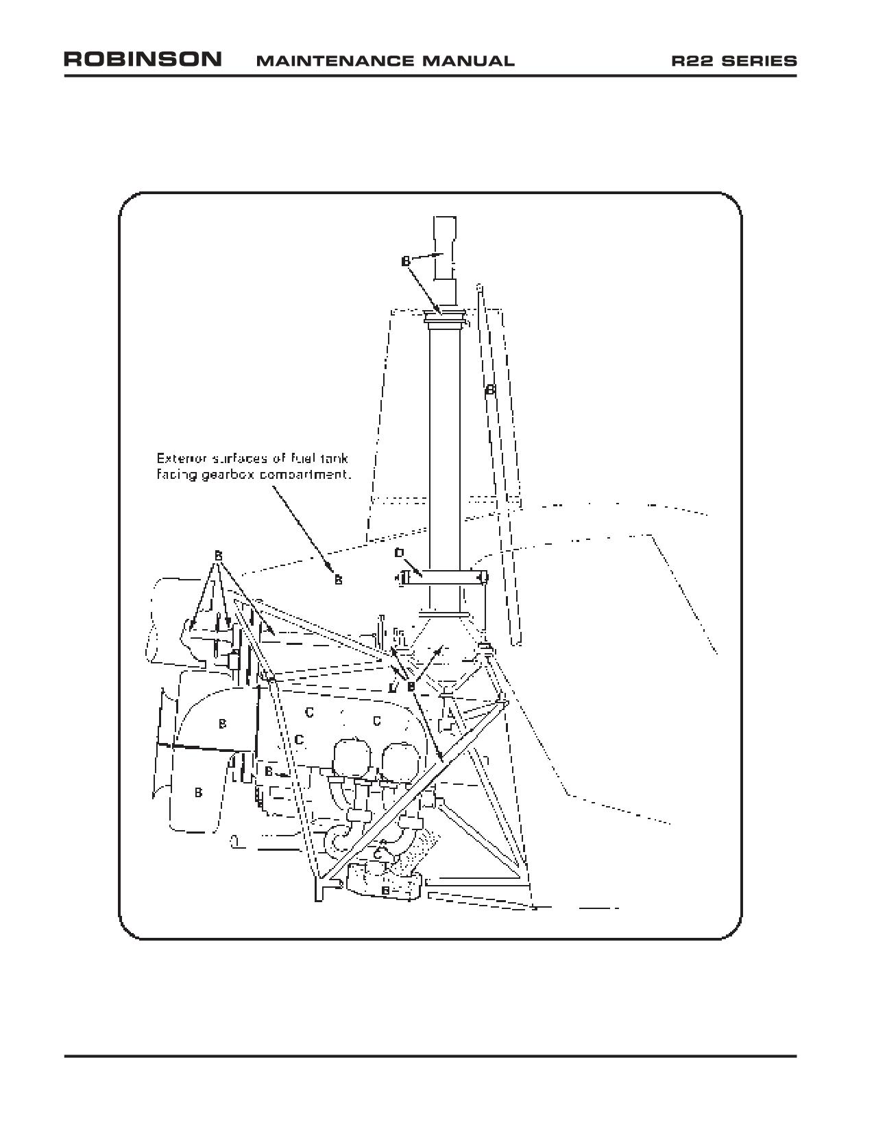
FIGURE 23-13 PAINT CODES
Page 23.24
Chapter 23 Standard Practices
OCT 2018
23-77 Paints (continued)
For limited touch-up of interior and landing gear only:
CODE
MATERIAL
MANUFACTURER
Cardinal Industries Finishes;
Cardinal A-2000-05 Flat black (aerosol can)
Cleveland, OH
A3
Krylon Div. of Borden
Krylon 1613 Semi-Flat Black (aerosol can)
Columbus, OH
23-78 Lubricants
RHC
MANUFACTURER’S
LUBRICANT TYPE
MANUFACTURER
PART NO.
PART NO.
A257-1
Grease
101
Southwestern Petroleum Corp.
(general purpose)
Fort Worth, TX
A257-2
Gear oil
201
Southwestern Petroleum Corp.
SAE 90
Fort Worth, TX
A257-3
Grease
Aero Shell 14
Shell Oil Co.
MIL-G-25537
A257-4
Oil
Dexron II or
Any
(automatic
Dexron II/Mercon or
transmission fluid)
Dexron III/Mercon
A257-6
Grease
Fuelube
Fleet Supplies Inc.
(fuel resistant)
Cleveland, OH
EZ Turn
United-Erie Div. of Interstate Chemical Co.
Erie, PA
A257-7
Dry film lubricant
Lubri-Kote
Mealey Ind. Lubricants
Type A 1040 CR
Cleveland, OH
A257-8
Rubber lubricant
P-80
International Products Corp.
Trenton, NJ
A257-9
Anti-seize
Silver Grade
Loctite Corp.
Newington, CT
A257-10
Substitute A257-16
A257-12
Grease
MobilGrease 28
Exxon Mobil Corp.,
MIL-PRF-81322
Fairfax, VA
A257-16
Engine Oil
Type M 20W-50,
Any
Approved for 0-90° F
SAE J1966
ambient). Substitute
A257-24 as required.
A257-17
Substitute A257-19
A257-19
Valve lubricant and
111
Dow Corning Corp.
sealant compound
Midland, MI
A257-24
Engine oil
SAE 50,
Any
(Approved for >60°F
SAE J1966
ambient)
OCT 2018
Chapter 23 Standard Practices
Page 23.25
23-79 Adhesives and Sealants
RHC
DESCRIPTION
COLOR
MFR. PART NO.
MANUFACTURER
PART NO.
B270-1
Sealant - manganese-cured, fuel
Gray
AC-730 B-*
3M Co.
resistant (2-part)
St. Paul, MN
B270-2
Substitute B270-1
B270-4
Substitute B270-13
B270-5
Sealant - synthetic rubber putty
White
Q4-2805
Dow Corning Corp.
(1-part)
Light Gray
94-031
Midland, MI
B270-6
Sealant & lubricant - thread
Gray
Titeseal 55
Radiator Spec. Co.
(1-part)
Charlotte, NC
B270-7
Substitute B270-14
B270-8
Adhesive - rubber, nitrile/acetone
Tan
C 160
Stabond Corp.
(1-part)
Gardena, CA
Adhesive - rubber, nitrile/acetone
Tan
843
3M Co.
(1-part)
St. Paul, MN
B270-9
Adhesive - epoxy, structural,
Gray
2216 B/A
3M Co.
flexible (2-part)
St. Paul, MN
B270-10
Adhesive/sealant - threadlocker,
Red
271
Henkel Loctite Corp.
anaerobic, tight-fits (1-part)
Rocky Hill, CT
B270-11
Adhesive/sealant - threadlocker,
Red
277
Henkel Loctite Corp.
anaerobic, loose-fits (1-part)
Rocky Hill, CT
B270-12
Sealant - electrical potting (2-part)
Any color
MIL-PRF-8516
Any
except red
Type II, Class 2,
Category A or B
B270-13
Sealant - silicone rubber,
Translucent
3145
Dow Corning Corp.
noncorrosive (1-part)
Midland, MI
B270-14
Substitute B270-8
B270-15
Adhesive - plastic, for vinyl
Clear
2262
3M Co.
(1-part)
St. Paul, MN
B270-16
Substitute B270-14
B270-17
Adhesive - cyanoacrylate, instant
Clear
Super Bonder
Henkel Loctite Corp.
(1-part)
495
Rocky Hill, CT
B270-18
Adhesive - weatherstrip (1-part)
Black
051135-08008
3M Co.
St. Paul, MN
B270-19
Adhesive - epoxy structural, rigid
Green
1838 B/A
3M Co.
(2-part)
St. Paul, MN
B270-20
Adhesive/sealant - threadlocker,
Purple
222 or 222MS
Henkel Loctite Corp.
anaerobic, non-permanent (1-part)
Rocky Hill, CT
B270-21
Protectant - corrosion, non-drying
Lt. Amber
LPS 3
LPS Laboratories, Inc.
(1-part)
Tucker, GA
Page 23.26
Chapter 23 Standard Practices
OCT 2018
23-79 Adhesives and Sealants (continued)
RHC PART
DESCRIPTION
COLOR
MFR. PART NO.
MANUFACTURER
NO.
B270-22
Protectant - corrosion, drying
Amber
LPS Hardcoat
LPS Laboratories, Inc.
(1-part)
Tucker, GA
B270-23
Sealant - gasket (1-part)
Brown
GM3H (Gasket
Perfect Seal, Inc.
Maker #4)
Cincinnati, OH
Sealant - gasket (1-part)
Brown
JV66B
Dana Corp.;
Churubusco, IN
(Victor Reinz Brand)
B270-24
Activator/primer - anaerobic
Translucent
7649
Henkel Loctite Corp.
adhesive (1-part)
Green
Rocky Hill, CT
B270-25
Clear coat - automotive touch
Clear
Clear Coat
Automotive Touchup
up, brush in bottle (1-part)
Touch up Bottle
Harahan, LA
B270-26
Sealant - polysulfide, window
Black
AC-251 B-1
3M Co.
glazing (2-part)
St. Paul, MN
B270-27
Adhesive - epoxy, high strength
Translucent
EA 9309NA
Henkel Loctite Corp.
structural, flexible (2-part)
Red Blue
EA 9309.2NA
Rocky Hill, CT
B270-28
Substitute B270-27
* Dash number for minimum hours application life may be -½, -2, -6, or -12.
OCT 2018
Chapter 23 Standard Practices
Page 23.27
23-80 Miscellaneous Practices
23-81 Part Interchangeability
Refer to R22 Illustrated Parts Catalog for part interchangeability information.
23-82 Thermal Fitting Parts
General Procedures for using heat to fit parts during assembly or evaluating parts that
may have been overheated in service:
Aluminum parts must not be heated above 200º F for more than 5 minutes. Higher
temperatures or longer times adversely affect strength and corrosion properties. Scrap
any aluminum parts suspected of going above 325º F regardless of time at temperature.
Steel parts (bare) - Maximum temperature 300º F. Higher temperature can reduce the
strength or cause temper brittleness in some alloys.
Steel parts (cadmium plated) - Maximum temperature 300º F. Higher temperatures
will melt the plating and adversely affect steel strength by a process called liquid metal
embrittlement.
Bearings and carburized parts such as gears, clutch shafts, and clutch housings should
not be heated above 300º F. Higher temperatures will reduce the surface hardness and
increase wear rates.
Always heat parts in an oven with temperature control set no greater than the maximum
temperature allowed for the part.
Always attach a pyrometer and thermocouple to the smallest aluminum part in the oven.
Never depend on the oven control to determine part temperature.
Cooling a part for thermal fitting at assembly is not recommended. Water vapor from the
air will condense on the part and frequently introduce water into the assembly causing
severe internal corrosion over time.
23-83 Replacement Component Identification (Data) Plates
In order to issue a replacement component identification plate for field installation, RHC
must first receive the old identification plate in legible condition. If old identification
plate is lost or destroyed, then RHC must have an original letter (photocopies or faxes
are NOT acceptable) from customer’s Civil Aviation Authority authorizing identification
plate replacement AND stating component name, part number, and serial number for each
requested identification plate. There is a charge for each plate issued.
Identification plates may be carefully removed using a sharp plastic scraper. If necessary,
use a heat gun to soften plate adhesive. Retain in a dry, contaminate-free area until ready
for reinstallation.
Damp wipe local area with acetone or equivalent solvent prior to reinstallation. Residual
adhesive on identification plate is usually sufficient for good adhesion. If necessary, use
B270-9 adhesive or equivalent to secure.
Page 23.28
Chapter 23 Standard Practices
OCT 2018
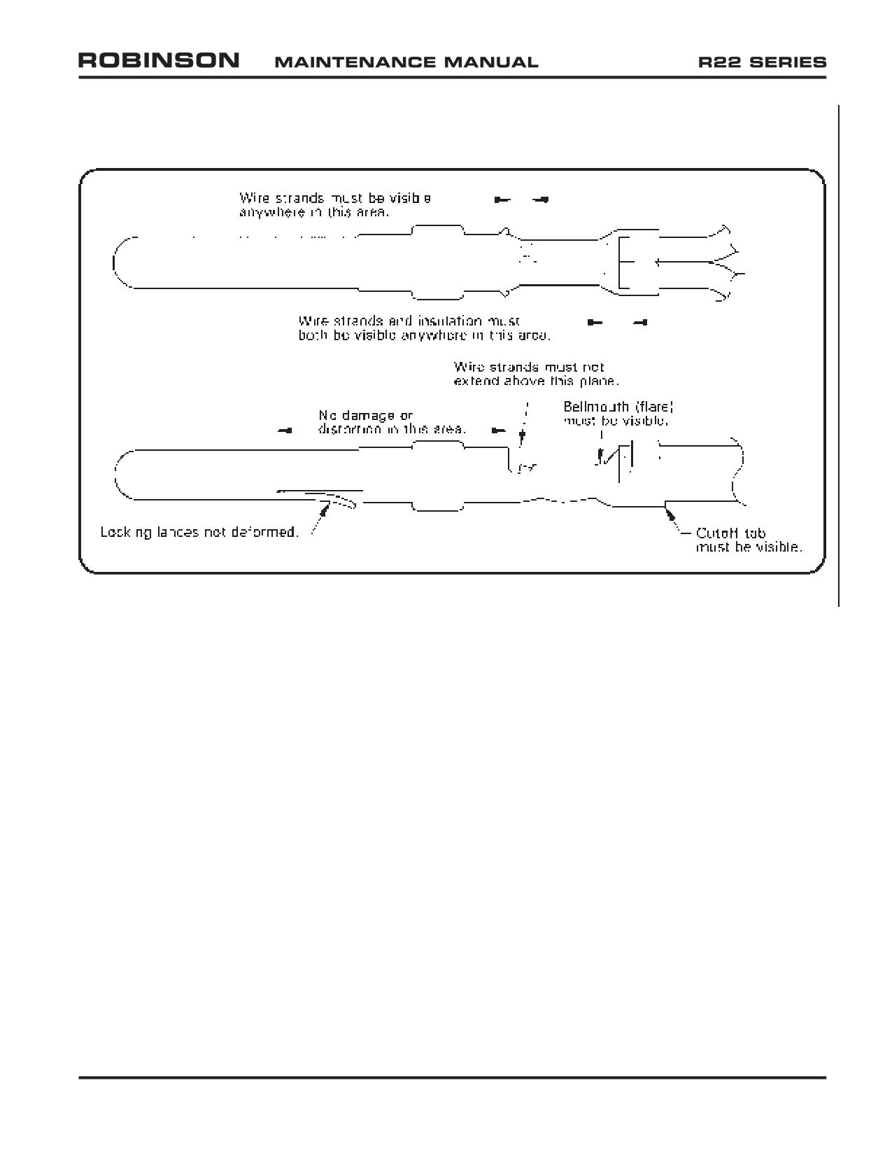
23-84 Crimp Inspection
Refer to Figure 23-14.
FIGURE 23-14 CRIMP INSPECTION
OCT 2018
Chapter 23 Standard Practices
Page 23.29
23-85 Storage Limits
1. B283 hoses have a shelf storage life of 5 years. Hose service life is “on condition”,
with a maximum of 12 years.
2. Elastic cords have a shelf storage life of 5 years. Elastic cord service life is “on condition”,
with a maximum of 12 years. Use invoice or FAA Form 8130 date as start date.
3. Store V-belts at less than 85º F (30º C), with relative humidity below 70%. Avoid
solvent and oil vapors, atmospheric contaminants, sunlight, and ozone sources (electric
motors, arc welding, ionizing air purifiers, etc.). Belt shelf life is 4 years if preceding
recommendations are followed. Use invoice date or FAA Form 8130 date as start date.
4. Oils and greases have a 5 year shelf life when stored and kept sealed in their original
container. Use invoice date or FAA Form 8130 date as start date unless the manufacturer
has marked container with manufacture date (in which case use manufacture date as
start date).
5. Rubber o-rings, seals, and gaskets have a twenty (20) quarter, five (5) year shelf life
from the indicated cure date. Fluorocarbon (Viton) and silicon rubber products shall
adhere to manufacturer’s expiration date(s). Service life is “on condition” with a
maximum of 12 years.
6. Store uninstalled fuel bladder in original container (if available) at 70°F to 80°F and
below 70% humidity. Coat bladder with clean, non-detergent engine mineral oil to
prevent rubber from drying out and cracking. Store bladder in relaxed condition free
from tension, compression, or other deformation such as creases or folds.
23-86 B526 Screws and B527-08 Washers
B526 (TORX Plus®) truss head screws may be used to secure cowlings and access panels.
A B527-08 nylon washer may be used under a B526 screw head to further protect thin
or painted surfaces.
B526 screws are interchangeable with MS27039C080_ screws used to secure cowlings
and access panels as follows:
PART:
INTERCHANGEABLE WITH:
MS27039C0806 screw
B526-6 screw
MS27039C0807 screw
B526-8 screw
MS27039C0808 screw
B526-8 screw
B526 screws are interchangeable with AN525-832R_ & AN526C832R_ screws as follows:
PART:
INTERCHANGEABLE WITH:
AN525-832R6 or AN526C832R6 screw
B526-6 screw
AN525-832R7 or AN526C832R7 screw
B526-8 screw
AN525-832R8 or AN526C832R8 screw
B526-8 screw
NOTE
B526 screws are compatible with T20 or 20IP drivers.
Page 23.30
Chapter 23 Standard Practices
OCT 2018
CHAPTER 24
LIGHTS
Section Title
Page
24-00
Description
24.1
24-10
Exterior Lights
24.1
24-11
Strobe Light
24.1
24-12
Navigation Lights
24.2
24-13
Landing Lights
24.3
24-20
Interior Lights
24.4
24-21
Instrument Lighting
24.4
OCT 2018
Chapter 24 Lights
Page 24.i
Intentionally Blank
Page 24.ii
Chapter 24 Lights
OCT 2018
CHAPTER 24
LIGHTS
24-00 Description
A red anti-collision light is installed on the tailcone and is controlled by the strobe switch.
Position lights are installed on each side of the cabin and in the tail and are controlled by
the nav lights switch. Post and internal lights (earlier aircraft) or a light at the top of the
windshield (later aircraft) illuminate the instruments. Instrument lighting is active when the
nav lights switch is on and lighting is dimmed via the knob above the nav lights switch.
An overhead map light mounted on a swivel is controlled by an adjacent switch. The map
light may be used for emergency lighting of the instrument panel.
Two landing lights are installed in the nose at different vertical angles to increase lighted
area. One landing light switch controls both lights and is located on the cyclic center post
or near OAT gage.
NOTE
Landing lights operate only when clutch actuator switch is in
the engage position.
24-10 Exterior Lights
24-11 Strobe Light
A. Removal
1. Turn battery switch off. Pull out STROBE circuit breaker (5 amp) at panel.
2. Remove hardware securing A708 strobe light assembly's retainer (or clamp),
lens, and gasket to strobe (or flash tube assembly).
3. Remove screws securing A708-14 strobe to tailcone mount.
4. Disconnect strobe (or flash tube assembly) wire harness from airframe harness at
connectors and remove strobe (or flash tube assembly).
OCT 2018
Chapter 24 Lights
Page 24.1
24-11 Strobe Light (continued)
B. Installation
1. Turn battery switch off. Pull out STROBE circuit breaker (5 amp) at panel.
2. Connect A708 strobe light assembly’s wire harness to airframe harness at
connectors. Verify security.
3. Loop wires and connectors inside mount and install screws securing A708-14
strobe to tailcone mount.
4. Assemble gasket, lens (red forward if red/white), and retainer (or clamp) on
tailcone mount and install hardware. Verify security.
5. Push in STROBE circuit breaker (5 amp) at panel. Turn battery switch and strobe
switch(es) on and verify function. Turn battery switch off.
24-12 Navigation Lights
A. Removal
1. Turn battery switch off. Pull out LTS circuit breaker (5 amp) at panel.
2. a. Position Lights: Remove screw, retainer, lens, (lamp), and gasket to light
assembly. Remove hardware securing light assembly, gasket, and ground
wire to chin. Cut and discard ty-rap securing excess wire to light assembly,
pull out light assembly, and disconnect light assembly harness from airframe
harness at connectors.
b. Tail Light: Remove screws securing retainer, lens, gasket, (lamp), and light
assembly to stabilizer mount. Pull out light assembly and disconnect light
assembly harness from airframe harness at connectors.
B. Installation
1. Turn battery switch off. Pull out LTS circuit breaker (5 amp) at panel.
2. a. Position Lights: Connect light assembly harness to airframe harness at
connectors. Install hardware securing light assembly, gasket, and ground wire
to chin. Verify security. Install ty-rap securing excess wire to light assembly.
Cinch ty-rap until snug without over-tightening, and trim tip flush with head.
Install lamp (earlier R22s). Install screw securing retainer, lens, and gasket to
light assembly. Verify security.
b. Tail Light: Connect light assembly harness to airframe harness at connectors.
Position light assembly in stabilizer mount and install screws securing retainer,
lens, gasket, and light to mount. Verify security.
3. Push in LTS circuit breaker (5 amp) at panel. Turn battery switch and NAV LTS
switch on and verify function. Turn battery switch and NAV LTS switch off.
Page 24.2
Chapter 24 Lights
OCT 2018
24-13 Landing Lights
NOTE
Landing lights operate only when clutch actuator switch is in
the engage position.
A. Removal
1. Turn battery switch off. Pull out LAND LT circuit breaker (15 amp for HIDs, 20
amp for B196-26 lamps) at panel.
2. Remove screws securing A526-1 retainer to chin and remove retainer.
3. Unplug landing light cable from (or remove hardware securing landing light wires
to) lamp and remove lamp.
B. Installation
1. Turn battery switch off. Pull out LAND LT circuit breaker (15 amp for HIDs, 20
amp for B196-26 lamps) at panel.
2. a. HIDs: Connect landing light cable to B557-1 (spot; LH) landing light or B557-2
(flood) taxi light, as required. Verify security.
b. B196 lamps: Install hardware securing landing light wires to lamp. Verify
security.
3. Install screws securing A526-1 retainer to chin.
4. Push in LAND LT circuit breaker (15 amp for HIDs, 20 amp for B196-26 lamps)
at panel. Turn battery switch and landing light switch on (cyclic center post) and
verify function. Turn battery switch and landing light switch off.
OCT 2018
Chapter 24 Lights
Page 24.3
24-20 Interior Lights
24-21 Instrument Lighting
A. LED Assembly Replacement
1. Turn battery switch off. Pull out LTS circuit breaker (5 amp) at panel.
2. Remove hardware securing G196-6 light assembly to windshield stiffener.
Remove two cap screws securing cover and LED-lamp assembly to housing.
Disconnect lamp wires from airframe harness and remove lamp.
3. Connect A238-2289 (white) airframe harness wire to LED-lamp assembly red
wire, and A238-2290 airframe harness wire to lamp black wire. Install cover
(chamfer facing away from housing) and install two cap screws. Install hardware
securing G196-6 light assembly to windshield stiffener. Verify security.
4. Push in LTS circuit breaker (5 amp) at panel. Turn battery switch and NAV LTS
switch on and verify function. Verify dimming knob adjusts brightness. Turn
battery switch and NAV LTS switch off.
Page 24.4
Chapter 24 Lights
OCT 2018
CHAPTER 25
DOORS AND WINDOWS
Section Title
Page
25-00
Description
25.1
25-10
Door Assembly
25.1
25-20
Windshield Assembly
25.3
OCT 2018
Chapter 25 Doors and Windows
Page 25.i
Intentionally Blank
Page 25.ii
Chapter 25 Doors and Windows
OCT 2018
CHAPTER 25
DOORS AND WINDOWS
25-00 Description
Both cabin doors may be removed and installed by maintenance personnel or pilots.
25-10 Door Assembly
A. Removal
Remove cotter pins from door hinge pins. Open door and lift door pins from door
frame hinge assemblies and remove door. Adjust weight and balance as required.
B. Installation
WARNING
Failure to install a cotter pin in each door's two hinge pins may
allow door to depart aircraft in flight.
1. Align and insert door hinge pins in door frame hinge assemblies; latch door.
2. Install a cotter pin in both upper and lower door hinge pins.
3. Adjust weight and balance as required.
OCT 2018
Chapter 25 Doors and Windows
Page 25.1
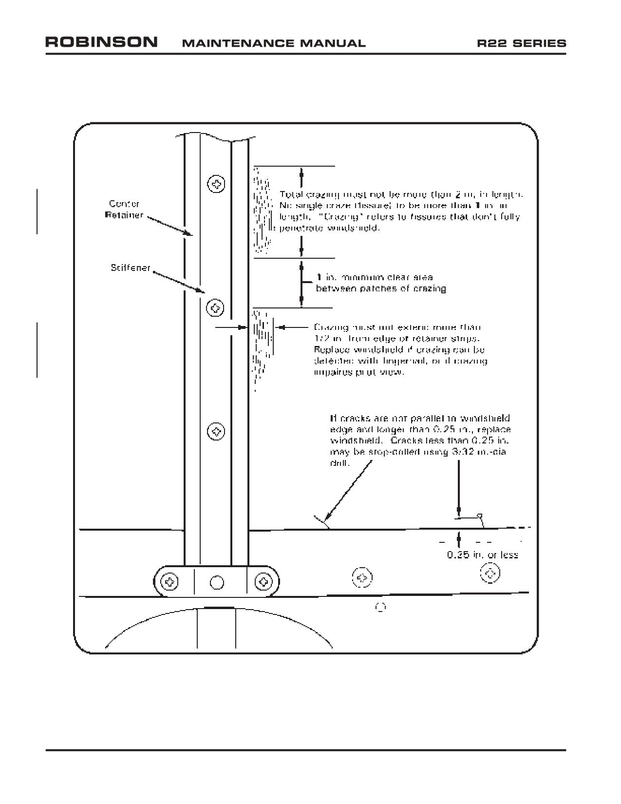
FIGURE 25-1 WINDSHIELD INSPECTION
Page 25.2
Chapter 25 Doors and Windows
OCT 2018
25-20 Windshield Assembly
A. Removal
1. Remove forward door and hinges.
NOTE
To prevent scratching windshield, a protective cover should
be taped to the inside and outside of the windshield prior to
removal.
2. Remove screws and side retainer holding windshield.
3. Reinstall hinges and doors for cabin structure support with windshield removed.
4. Remove screws and retainers (upper, lower, and middle) holding windshield.
5. Clean silicone from retainers.
6. Clean silicone from windshield for reinstallation.
B.
Installation
1. Remove all old silicone from cabin, retainers and windshield.
2. Install windshield and cleco retainer strips.
3. Mask windshield along edge of retainer strips with 1/2” masking tape. This will
catch silicone rubber squeeze-out on installation of retainer strips.
4. Remove retainer strips.
5. To ensure a proper seal, run a bead of B270-13 silicone rubber along entire edge
of tape line.
6. While holding windshield in place, cleco retainer strips (center, upper and lower)
into place.
7. With doors installed and closed, tighten center retainer strip first. Then tighten
upper and lower retaining strips. A second person will be required to tighten nuts
inside ship.
8. When center, upper and lower retaining strips are secure, remove door and hinges
for side strip installation.
9. Install side retainer strip.
10. Reinstall hinges and door. Ensure all fasteners are tight.
11. Fill any gap between retainer and window with B270-13 silicone rubber.
12. Remove masking tape next to retainers. Be careful not to smear wet silicone.
13. Clean any silicone off windshield after it has been allowed to dry.
OCT 2018
Chapter 25 Doors and Windows
Page 25.3
25-20 Windshield Assembly (continued)
C. Inspection
1. Inspect windshield for cracks and crazing adjacent to retainer strips per Figure
25-1. If cracks exceed these limits, replace windshields per § 25-20 Part D.
D. Replacement
1. Remove all old silicone on cabin and retainers if they are to be reused.
2. Cleco all window retaining strips in place, checking for proper alignment.
3. Install hinges and doors in door frames and secure. Remove bottom and center
retaining strips, leaving side retaining strip to hold door and door frame in position.
4. Hold windshield in place by hand, and align it with frame according to contour of
frame and windshield.
5. Mark windshield for trim using non-permanent marker, such as grease pencil or
masking tape.
6. Trim to mark. A band saw is recommended. Band saw blade should contain at
least 24 teeth per inch.
NOTE
Tape cardboard to band saw table to prevent scratching of
windshield. Saw carefully to prevent binding of saw blade and
cracking windshield.
7. Hold windshield in place and check for fit. Re-trim as necessary.
8. After windshield is fitted, carefully sand or scrape edges smooth.
9. Install windshield per § 25-20 Part B.
Page 25.4
Chapter 25 Doors and Windows
OCT 2018
CHAPTER 26
MAIN ROTOR
Section Title
Page
26-00
Description
26.1
26-10
Main Rotor Blades
26.1
26-11
Blade Boots
26.6
26-12
Filling Pitch Bearing Housing
26.9
26-20
Main Rotor Hub
26.10
26-21
Bearing Replacement
26.12
26-30
Main Rotor Assembly
26.15
26-31
Journal and Shim Calculations
26.15
26-32
Adjusting Hinge Friction
26.20
26-33
Shifting the Main Rotor Hub
26.21
26-34
Drilling Installed Main Rotor Hub Bolts
26.21
26-40
Inspection of Main Rotor Blades
26.23
26-41
Scratches and Corrosion on Blade Skins and Doublers
26.23
26-42
Dents
26.25
26-43
Root Fitting Damage
26.27
26-44
Voids
26.29
26-50
Repair of Main Rotor Blades
26.31
26-51
Trimming
26.33
26-52
Painting
26.33
OCT 2018
Chapter 26 Main Rotor
Page 26.i
Intentionally Blank
Page 26.ii
Chapter 26 Main Rotor
OCT 2018
CHAPTER 26
MAIN ROTOR
26-00 Description
The main rotor has two all-metal blades mounted to the hub by coning hinges. The hub is
mounted to the shaft by a teeter hinge. The coning and teeter hinges use self-lubricated
bearings. Droop stops for the main rotor blades provide a teeter hinge friction restraint
which normally prevents the rotor from teetering while starting or stopping. Pitch change
bearings for each blade are enclosed in a housing at the blade root. The housing is filled
with oil and sealed with an elastomeric boot. Each blade has a thick stainless steel spar at
the leading edge which is resistant to corrosion and erosion. The skins are bonded to the
spar approximately one inch aft of the leading edge. Blades must be refinished if the paint
erodes to bare metal at the skin-to-spar bond line. Bond may be damaged if bond line is
exposed.
26-10 Main Rotor Blades
WARNING
Due to potentially destructive results, use of blade tape (anti-
erosion tape) is prohibited.
A. Removal
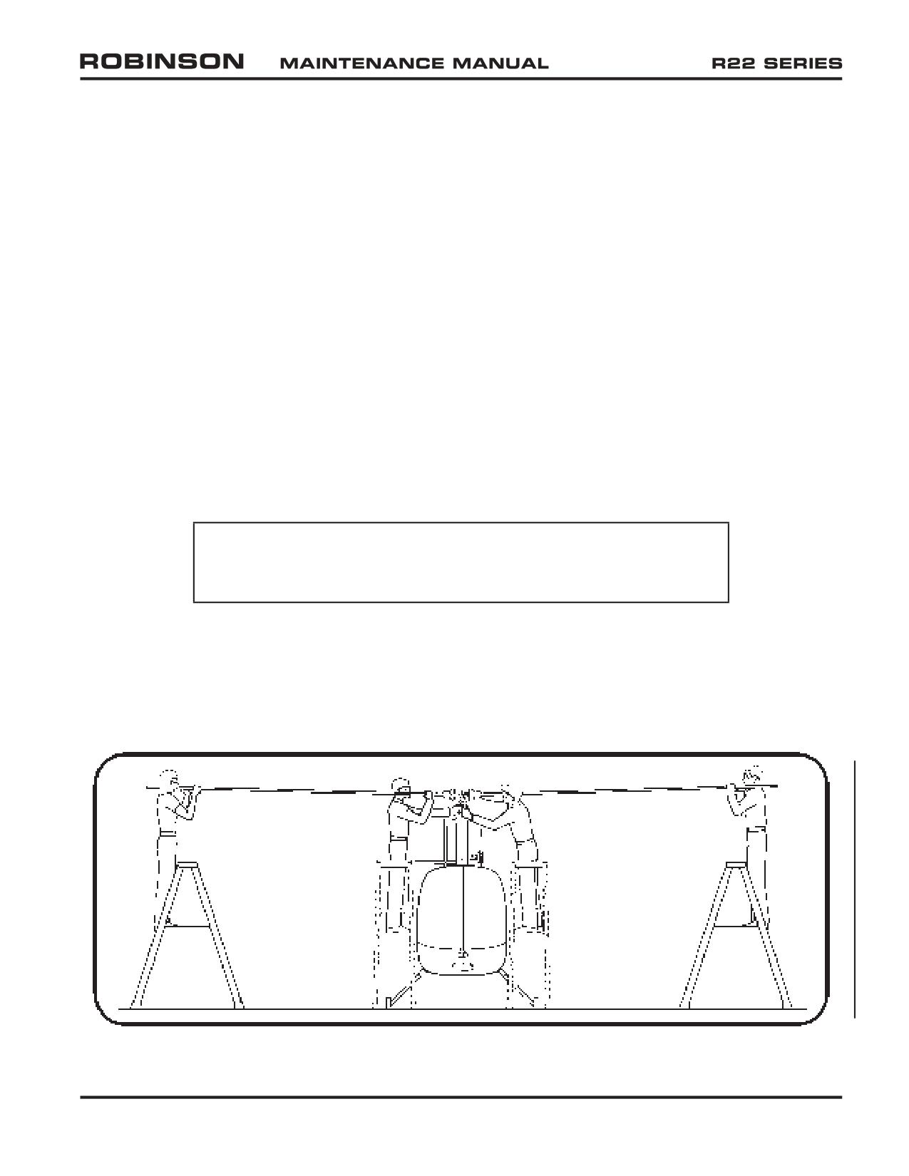
Refer to Figure 26-1. Four people will be required to remove the blades. One person
must support the blade near the blade tip while another supports the root and removes
or installs the attachment bolt.
FIGURE 26-1 SUPPORTING MAIN ROTOR BLADES DURING BLADE REMOVAL OR INSTALLATION
OCT 2018
Chapter 26 Main Rotor
Page 26.1
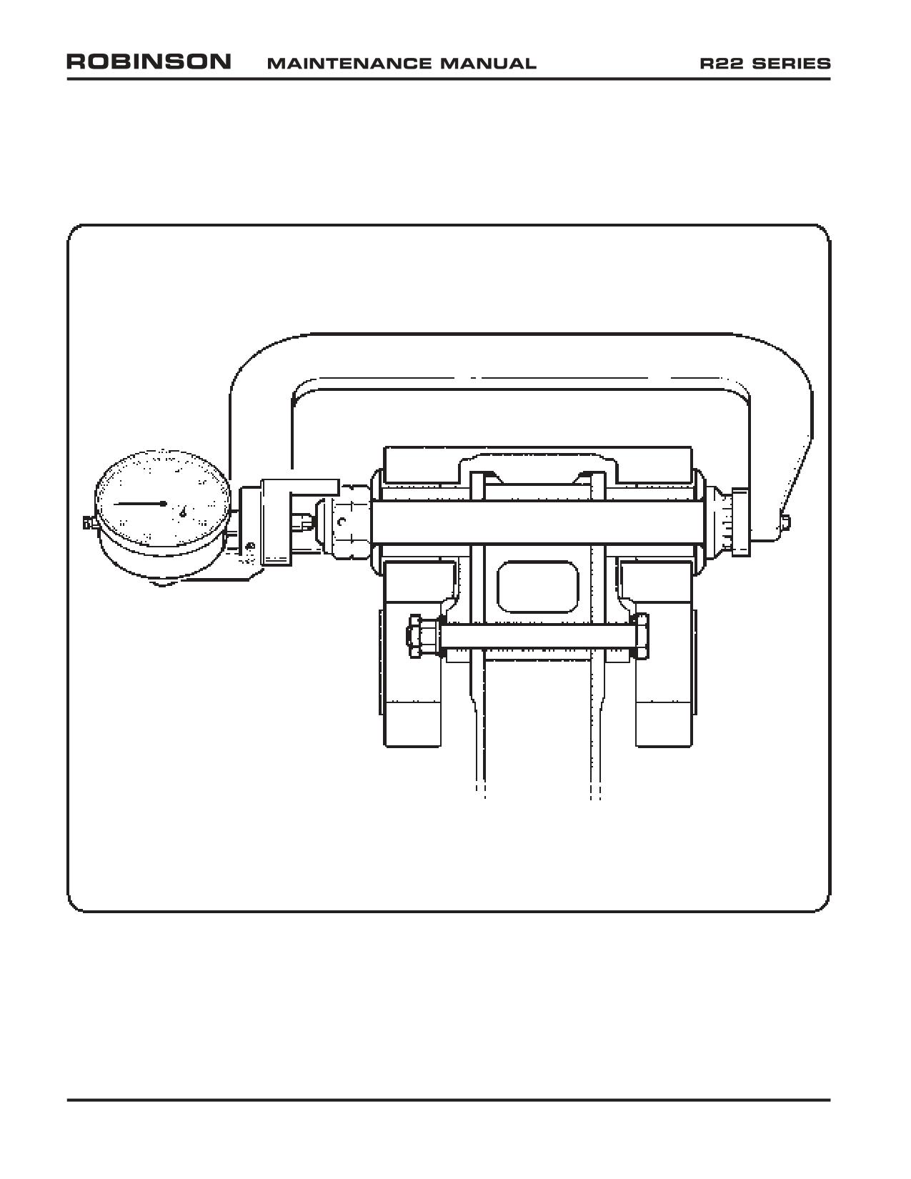
FIGURE 26-2 MEASURING BOLT STRETCH (SHOWN ON TEETER BOLT, BLADES REMOVED)
Page 26.2
Chapter 26 Main Rotor
OCT 2018
26-10 Main Rotor Blades (continued)
A. Removal (continued)
1.
Mark one main rotor blade and its corresponding hub location, pitch link, and
retaining nut & bolt with “X” using a marker or grease pencil. Mark opposite blade
and its hub location, pitch link, and retaining nut & bolt with “O”.
2.
Measure and record coning hinge axial gaps per Figure 26-8.
3.
Remove hardware securing main rotor pitch links to blade pitch horns.
4.
Remove cotter pins and loosen blade coning hinge retaining nuts until finger tight.
CAUTION
After removing one blade, support installed blade in a level
position until it is removed.
5.
Remove nut, thrust washer, and trailing-edge shims (if used) from one blade. Cone
blade as required to position spindle tusk off of droop stop. Supporting blade at
root, rotate pitch horn down, and remove hinge bolt and thrust washer.
CAUTION
Do not drop journals (inside hub bearings) which can slide out
when removing blade bolt.
NOTE
Blade installation hardware is specific to each blade, each
blade’s leading and trailing edge, and each blade’s location in
hub. It is good practice after blade removal to install hardware
in hub finger tight exactly as removed.
6.
Place blade on a cushioned surface to prevent damage to skins.
7.
Remove opposite blade per steps 5 and 6.
OCT 2018
Chapter 26 Main Rotor
Page 26.3
26-10 Main Rotor Blades (continued)
B. Installation
1.
Identify hub and spindle part numbers and ensure correct corresponding installation
hardware.
2.
Check teeter hinge friction and adjust as required per § 26-32.
3.
If coning hinge axial gap recorded during blade removal was beyond tolerance, or if
corresponding hub bearing(s) or spindle was replaced, perform coning hinge journal
and shim calculation per § 26-31.
4.
Level hub and insert journals in hub bearings. Install thrust washer on blade bolt.
5.
Insert main rotor blade spindle in hub and align spindle and journal bores. Cone
blade as required to position tusk off of droop stop. Rotate pitch horn down and
install hinge bolt at leading-edge side.
NOTE
A bolt may be inserted from trailing-edge side to align spindle and
journal bores (it is pushed out as coning hinge bolt is installed).
6.
Install trailing-edge shims (if used) and thrust washer. Apply light coat A257-9
anti-seize to bolt threads and nut face. Install nut finger tight.
NOTE
Do not allow anti-seize to contact journals, shims, or hub bearing
areas. These areas must be clean and dry.
CAUTION
After installing one blade, support blade in a level position until
opposite blade is installed.
7.
Install opposite blade per steps 4 thru 6.
8.
Tighten nut on coning hinge bolt until journals and thrust washer are firmly seated.
Loosen nut until both thrust washers can be freely rotated.
9.
Refer to Figure 26-2. Install MT122 main rotor bolt elongation (stretch) tool on
hinge bolt. Zero dial indicator by rotating dial face and lock dial. Remove tool.
10.
Using wrenches with at least 150 ft-lb torque capacity, tighten nut until drilled
holes in nut and bolt align. Install MT122 tool and measure bolt elongation:
WARNING
Do not under-stretch or over-stretch teeter or coning hinge
bolts to obtain proper clamping force. Under-stretching or over-
stretching can cause failure.
Page 26.4
Chapter 26 Main Rotor
OCT 2018
26-10 Main Rotor Blades (continued)
B. Installation (continued)
10. a. A154-1 hub with NAS630-80 (or MS21250-10080) coning hinge bolts:
i. If bolt elongation is 0.015-0.017 inch, remove tool and install a new
cotter pin wet with epoxy primer.
ii. If bolt elongation is not 0.015-0.017 inch, remove old nut and old bolt
and install a new bolt and a new nut. Stretch new bolt per § 23-33, and
drill new nut and bolt per § 26-34. Install a new cotter pin wet with
epoxy primer.
b. B370-1 hub with NAS632-82 (or MS21250-12082) coning hinge bolts:
i. If bolt elongation is 0.010-0.012 inch, remove tool and install a new
cotter pin wet with epoxy primer.
ii. If bolt elongation is not 0.010-0.012 inch, remove old nut and old bolt
and install a new bolt and a new nut. Stretch new bolt per § 23-33, and
drill new nut and bolt per § 26-34. Install a new cotter pin wet with
epoxy primer.
11. Install hardware securing main rotor pitch link to pitch horn. Standard torque
hardware per § 23-32 and torque stripe per Figure 2-1.
12. Perform steps 8 thru 11 on opposite blade.
13. Track and balance main rotor blades per § 10.230.
OCT 2018
Chapter 26 Main Rotor
Page 26.5
26-11 Blade Boots
A. Removal
1. Remove main rotor blades per § 26-10.
2. Place a suitable drain container below pitch horn. Remove two B289-2 bolts and
drain fluid.
3. Remove outer boot clamp and hold boot back to expose inner boot clamp. Remove
inner clamp and peel boot from spindle.
B. Installation
1. Visually inspect and verify boot is undamaged. Carefully stretch new boot over
spindle.
2. Solvent-clean surfaces clamped by boot inner lip. Properly position boot inner lip;
install A165-1 (inner) clamp assembly and tighten clamp to 2.330 ± 0.005 inch
outside diameter. Rotate spindle and verify adequate clearance between clamp
assembly and pitch horn.
NOTE
When installing inner clamp, ensure that shoulder of boot inner
lip is not wedged beneath clamp or clamp may loosen in service.
Inspect boot interior and verify no cuts or punctures.
3. Stretch boot outer lip over pitch horn flange. Rotate spindle and align pitch horn
bolt hole with spindle bolt hole per Figure 26-3. Install A165-7 (outer) clamp
assembly and tighten clamp. Verify security.
4. Fill pitch bearing housing per § 26-12.
Page 26.6
Chapter 26 Main Rotor
OCT 2018
Intentionally Blank
OCT 2018
Chapter 26 Main Rotor
Page 26.7
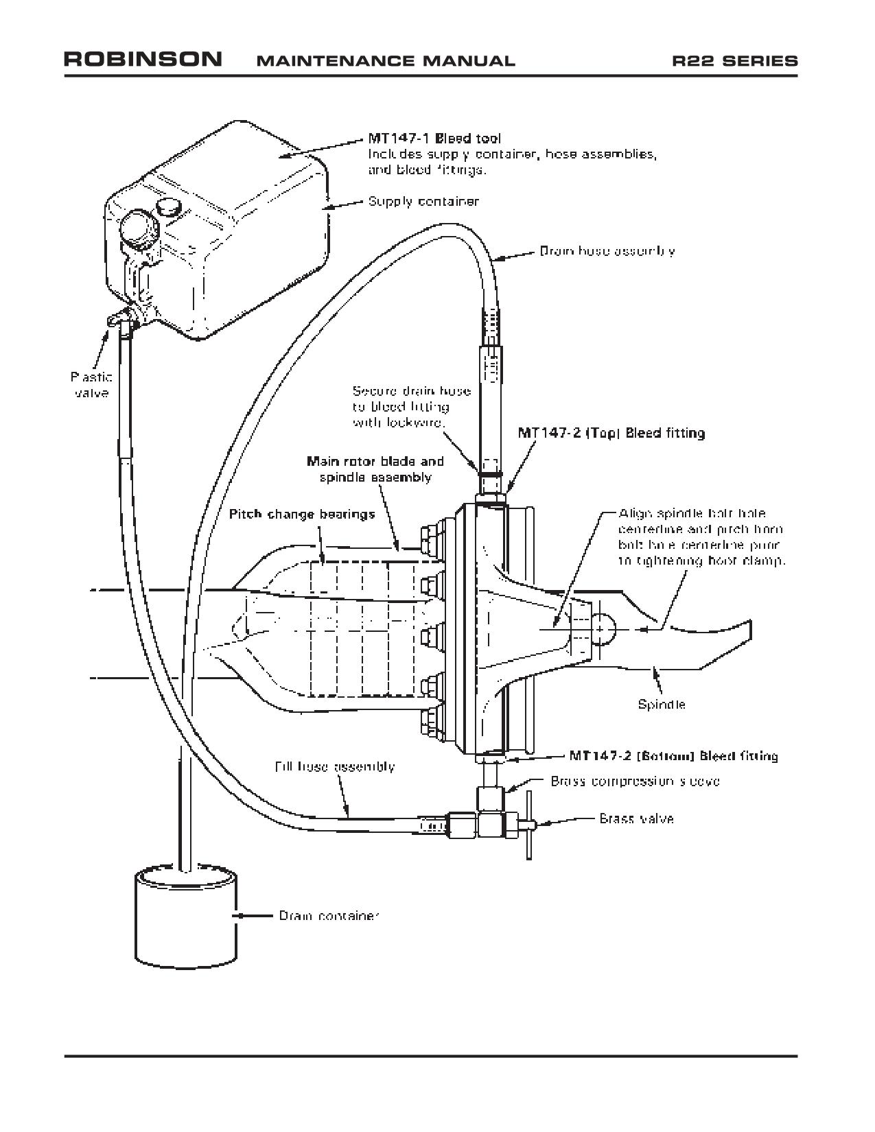
FIGURE 26-3 FILLING PITCH BEARING HOUSING
Page 26.8
Chapter 26 Main Rotor
OCT 2018
26-12 Filling Pitch Bearing Housing
NOTE
MT147-1 Main rotor blade spindle air bleed tool includes supply
container, hose assemblies, and bleed fittings.
WARNING
Refer to Safety Data Sheets (SDS) and observe precautions
when working in proximity to hazardous materials.
1.
Remove main rotor blades per § 26-10.
2.
Refer to Figure 26-3. Place a suitable drain container below main rotor pitch horn.
Remove two B289-2 bolts from pitch horn and drain fluid.
3.
Install MT147-2 bleed fittings into pitch horn openings. Attach drain hose assembly
to (top) bleed fitting, secure with two wraps of lockwire. Position drain hose into drain
container.
4.
Place supply container with sufficient A257-4 fluid approximately 3 feet above spindle.
Route fill hose assembly into drain container and open brass valve. Open supply
container plastic valve and purge air from fill hose. Close valves.
5.
Connect brass valve to (bottom) bleed fitting by tightening brass compression sleeve.
6.
Open valves and fill spindle housing until no air bubbles are visible in drain hose
assembly. Massage spindle boot, oscillate spindle, and raise blade tip up & down to
remove trapped air.
7.
Remove drain hose assembly and (top) bleed fitting, and install B289-2 bolt. Roll the
blade over. After five minutes, inspect the boot for leaks. If no leaks are found, close
valves, remove fill hose assembly brass valve and (bottom) bleed fitting, and install
other bolt.
8.
Special torque B289-2 bolts per § 23-33 and torque stripe per Figure 2-1.
9.
Repeat steps for opposite blade.
OCT 2018
Chapter 26 Main Rotor
Page 26.9
26-20 Main Rotor Hub
A. Removal
1. Remove main rotor blades per § 26-10.
2. Refer to Figure 26-5. Mark rotor hub using a grease pencil, tape, or soft marker as
follows:
a. Indicate nut side of teeter bolt.
b. Indicate chord arm side of drive shaft.
3. If same hub will be installed, measure teeter hinge friction per Figure 26-9 and
record value.
4. Remove cotter pin, nut, A152 thrust washers, A117 shims, A106 journals, and
bolt. Rotate hub as required and remove hub. Do not drop thrust washers or
journals.
5. Reinstall bolt, thrust washers, shims, journals, and nut in rotor hub exactly as
removed.
CAUTION
Main rotor chordwise balance is adjusted using A106 journals
and A117 shims. If assembly stack-up is altered, an out-of-
balance condition can occur.
B. Installation
1. Clean and dry teeter hinge hardware using approved solvent per § 23-70. Inspect
journals and thrust washers for chipping of chrome plating, corrosion, and/or wear
grooves extending through chrome plating. Replace journal or thrust washer if any
of these conditions exist.
2. If teeter hinge friction recorded during hub removal was less than 5 ft-lb or more
than 15 ft-lb, if teeter hinge hub bearing(s) was replaced, or if previous installation
information is unavailable, perform teeter hinge journal and shim calculation per
§ 26-31.
3. Refer to Figure 26-5. Line up mark on hub with chord arm on drive shaft. Install
teeter hinge bolt, thrust washers, shims, and journals (if previous installation
information is available, install parts exactly as removed).
Page 26.10
Chapter 26 Main Rotor
OCT 2018
26-20 Main Rotor Hub (continued)
B. Installation (continued)
4.
Coat nut face and bolt threads with A257-9 anti-seize compound, install and
tighten nut, then loosen nut until both thrust washers can be freely rotated. Ensure
journals do not “pinch” droop stops and fully contact drive shaft.
WARNING
Do not allow anti-seize compound to contaminate drive shaft,
journals, shims, or thrust washer inner faces. Contamination
prevents proper joint clamp-up and may cause failure.
5.
Refer to Figure 26-2. Install MT122 main rotor bolt elongation (stretch) tool on
teeter bolt. Zero dial indicator by rotating dial face and lock dial. Remove tool.
6.
Using wrenches with at least 150 ft-lb torque capacity, tighten nut until drilled
holes in nut and bolt align. Install MT122 tool and measure bolt elongation:
a. If bolt elongation is 0.015-0.017 inch, remove tool and verify correct teeter
hinge friction per § 26-32. Adjust teeter hinge friction as required.
b. If bolt elongation is not 0.015-0.017 inch, remove old nut and old bolt and
install a new bolt and a new nut. Stretch new bolt per § 23-33 and verify
correct teeter hinge friction per § 26-32. Adjust teeter hinge friction as
required. Drill new nut and bolt per § 26-34.
WARNING
Do not under-stretch or over-stretch teeter or coning hinge
bolts to obtain proper clamping force. Under-stretching or over-
stretching can cause failure.
7.
Install a new cotter pin wet with epoxy primer.
OCT 2018
Chapter 26 Main Rotor
Page 26.11
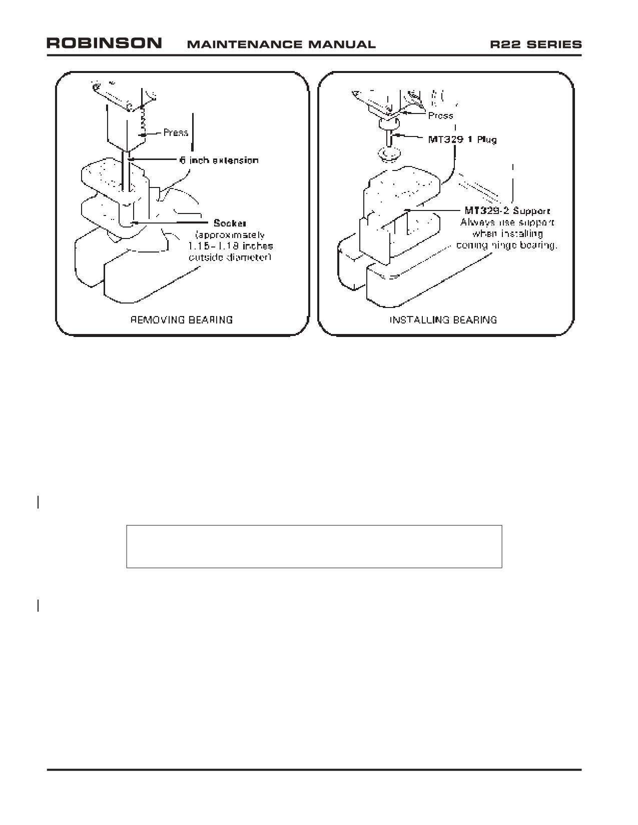
FIGURE 26-4 MAIN ROTOR HUB BEARING REPLACEMENT
26-21 Bearing Replacement
1.
Remove main rotor hub per § 26-20.
2.
Refer to Figure 26-4. Verify tooling surfaces are smooth to avoid damaging hub and
bearings. Press A648-1 and/or A648-3 bearing(s) from hub using MT329-1 plug
assembly (Rev H or subsequent) with MT329-10 tube. Press A648-2 bearing(s) from
hub using MT329-11 plug assembly with MT329-10 tube.
3.
Visually inspect hub bearing bore(s) per § 2.610 step 3a.
NOTE
Do not allow epoxy primer to contact bearing’s Teflon liner.
4.
Verify bearing mating surfaces are smooth and clean and apply light coat of epoxy
primer (refer to § 23-70). If visible, orient coning hinge bearing’s Teflon liner seam
toward top of hub. While primer is wet, press in new A648-1 and/or A648-3 bearing(s)
using MT329-1 plug assembly or A648-2 bearing(s) using MT329-11 plug assembly
(always use MT329-13 or MT329-2 [A154-4 Hub] support when replacing coning
hinge bearing) until bearing flange is completely seated against hub.
5.
Using a syringe, seal between bearing’s outboard flange and hub and bearing’s inboard
edge and hub with small fillet of epoxy primer.
Page 26.12
Chapter 26 Main Rotor
OCT 2018
Intentionally Blank
OCT 2018
Chapter 26 Main Rotor
Page 26.13
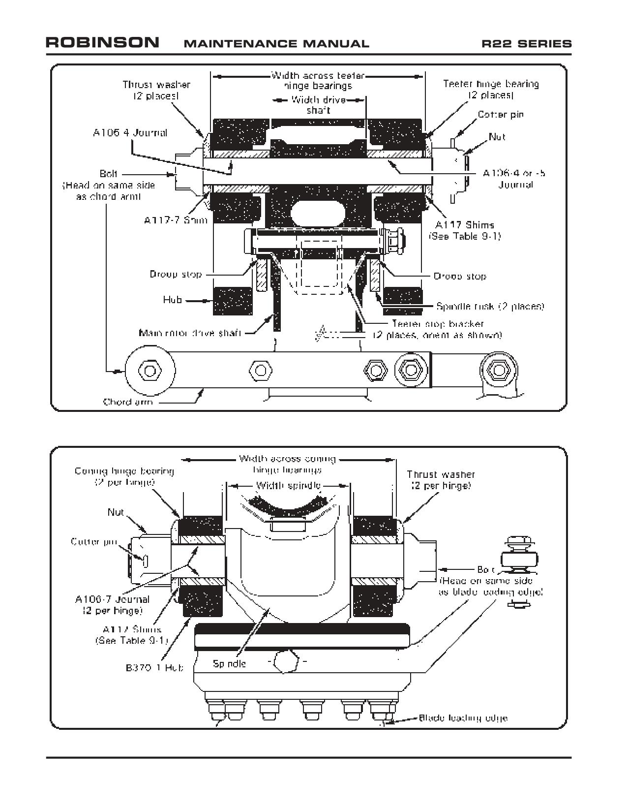
FIGURE 26-5 TEETER HINGE (HUB INSTALLATION)
FIGURE 26-6 B370-1 HUB CONING HINGE (BLADE INSTALLATION; VIEW LOOKING DOWN)
Page 26.14
Chapter 26 Main Rotor
OCT 2018
26-30 Main Rotor Assembly
26-31 Journal and Shim Calculations
Refer to Table 26-1 and Figures 26-5, 26-6, and 26-7.
A. Teeter Hinge Calculation
1.
Measure main rotor hub width across the teeter hinge bearing faces:
in.
2.
Subtract measured width of A251 driveshaft at teeter hinge bolt hole: -
in.
Calculated empty space: =
in.
3.
Assemble thrust washer, one A117-7 shim (0.020 inch), and one
A106-4 journal (1.300 inches) under the teeter bolt head and insert
bolt thru hub and drive shaft.
Subtract combined measured thickness of A117-7 shim &
A106-4 journal: -
in.
Difference: =
in.
4.
Subtract measured length of nut-side A106-4 or A106-5 journal:
-
in.
Difference: =
in.
CAUTION
Initial teeter hinge hardware stack-up must be adjusted to
0.005/0.008 inch greater than calculated empty space. A
smaller initial stack-up could damage thrust washers and hub
bearings during installation.
5.
To accommodate dimensional change due to clamping force, add: + 0.005/
0.008
in.
/
Initial A117 shim stack between nut-side journal & thrust washer: =
in.
NOTE
Use as many different size A117 shims as possible to facilitate
head shifting during balancing.
6.
Refer to § 26-32. Adjust shim stack as required to meet teeter hinge friction
requirement (less than 15 ft-lb).
OCT 2018
Chapter 26 Main Rotor
Page 26.15
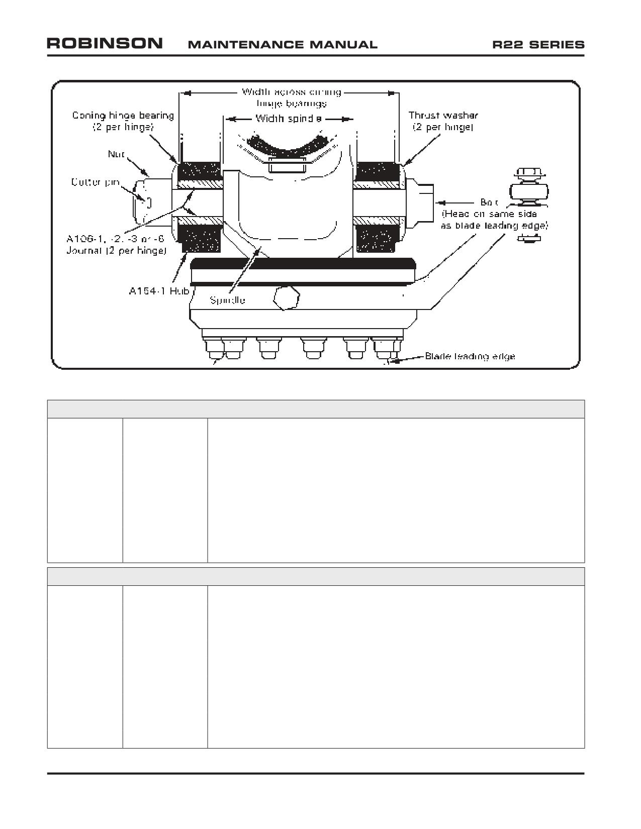
FIGURE 26-7 A154-1 HUB CONING HINGE (BLADE INSTALLATION; VIEW LOOKING DOWN)
A106 Journal Lengths
Part No.
Length
Location
A106-1
1.000 in.
Coning hinge, no shims (A154-1 Hub)
A106-2
0.995 in.
Coning hinge, no shims (A154-1 Hub)
A106-3
0.990 in.
Coning hinge, no shims (A154-1 Hub)
A106-4
1.300 in.
Teeter hinge (two, or one + A106-5 per hinge), shims
A106-5
1.260 in.
Teeter hinge (none, or one + A106-4 per hinge), shims
A106-6
1.005 in.
Coning hinge, no shims (A154-1 Hub)
A106-7
1.005 in.
Coning hinge (B370-1 Hub)
A117 Shim Sizes
Part No.
Thickness
Location (Between thrust washer and journal)
A117-5
0.012 in.
Teeter hinge
A117-6
0.015 in.
Teeter hinge
A117-7
0.020 in.
Teeter hinge
A117-8
0.025 in.
Teeter hinge
A117-48
0.012 in.
Coning hinge (B370-1 Hub)
A117-49
0.015 in.
Coning hinge (B370-1 Hub)
A117-50
0.020 in.
Coning hinge (B370-1 Hub)
A117-51
0.025 in.
Coning hinge (B370-1 Hub)
TABLE 26-1 A106 JOURNAL LENGTHS AND A117 SHIM SIZES
Page 26.16
Chapter 26 Main Rotor
OCT 2018
26-31 Journal and Shim Calculations (continued)
B. Coning Hinge Calculation
B370-1 Hub:
1. Measure main rotor hub width across the coning hinge bearing faces:
in.
2. Subtract measured width of blade spindle at teeter hinge bolt hole:
-
in.
Calculated empty space: =
in.
3. Subtract combined measured length of two A106-7 journals:
-
in.
Difference: =
in.
CAUTION
Initial teeter hinge hardware stack-up must be adjusted to
0.003/0.006 inch greater than calculated empty space. A
smaller initial stack-up could damage thrust washers and hub
bearings during installation.
4. To accommodate dimensional change due to clamping force, add: + 0.003/
0.006
in.
/
Initial A117 shim stack between nut-side journal & thrust washer: =
in.
5. Adjust shim stack combination as required to meet coning hinge axial gap
requirement per Figure 26-8 and to maintain teeter friction requirement as follows:
It must be possible to manually cone each blade without teetering the hub when
blades are held up off the droop stops and lifted at tip.
OCT 2018
Chapter 26 Main Rotor
Page 26.17
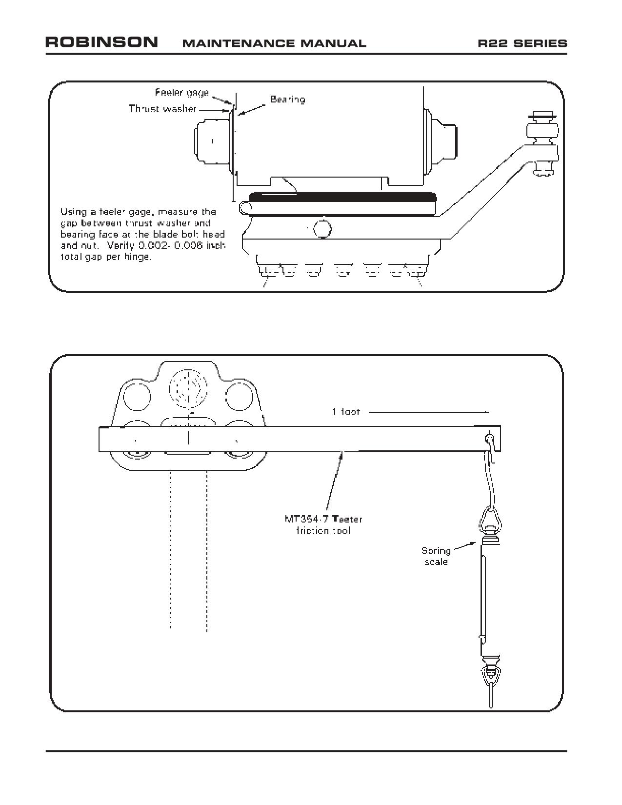
FIGURE 26-8 MEASURING CONING HINGE AXIAL GAP
FIGURE 26-9 MEASURING TEETER HINGE FRICTION
Page 26.18
Chapter 26 Main Rotor
OCT 2018
26-31 Journal and Shim Calculations (continued)
B. Coning Hinge Calculation (continued)
A154-1 Hub:
1. Measure main rotor hub width across the coning hinge bearing faces:
in.
2. Subtract measured width of blade spindle at coning hinge bolt hole: -
in.
Calculated empty space: =
in.
CAUTION
Initial coning hinge hardware stack-up must be adjusted to
0.003/0.006 inch greater than calculated empty space. A
smaller initial stack-up could damage thrust washers and hub
bearings during installation.
3. To accommodate dimensional change due to clamping force, add:
+ 0.003/
0.006
in.
/
Sum: =
in.
4. Select a combination of A106-1, -2, -3, or -6 journals whose combined measured
lengths equal Sum. The same journal dash number must be used under the head
of both coning hinge bolts to maintain symmetry.
5. Adjust journal combination as required to meet coning hinge axial gap requirement
per Figure 26-8 and to maintain teeter friction requirement as follows: It must be
possible to manually cone each blade without teetering the hub when blades are
held up off the droop stops and lifted at tip.
OCT 2018
Chapter 26 Main Rotor
Page 26.19
26-32 Adjusting Hinge Friction
A. Teeter Hinge Friction Adjustment
1. Remove main rotor blades per § 26-10.
2. Refer to Figure 26-5 and Table 26-1. Remove cotter pin, nut, thrust washer,
and nut-side A117 shims. Adjust teeter hinge friction by changing nut-side shim
stack thickness in small increments; reducing shim stack thickness increases
friction, increasing shim stack thickness reduces friction. Install shims, thrust
washer, and nut.
3. Refer to Figure 26-9. While torquing teeter hinge bolt per § 23-33, check teeter
hinge friction frequently. To check friction, install MT354 teeter friction tool
into coning hinge bearings on one side of main rotor hub and measure moving
force (not breakaway force) required to teeter main rotor hub with a spring scale.
Teeter friction must be less than 15 ft-lb.
4. Install a new bolt and nut per § 26-20.
B. Coning Hinge Friction Adjustment
1. Refer to Figure 26-6 and Table 26-1. Remove cotter pin, nut, thrust washer, and
cone blade to remove nut-side journal.
a. B370-1 Hub: Adjust coning hinge friction by changing trailing-edge shim
stack thickness in small increments; reducing shim stack thickness increases
friction, increasing shim stack thickness reduces friction. Coning hinge
friction is zero when there is a measurable axial gap per Figure 26-8. Install
shims, thrust washer, and nut.
b. A154-1 Hub: Adjust coning hinge friction by changing trailing-edge journal
length in small increments; using a shorter journal increases friction, using a
longer journal reduces friction. Coning hinge friction is zero when there is a
measurable axial gap per Figure 26-8. Install journal, thrust washer, and nut.
2. Install a new bolt and nut per § 26-20, steps 5 thru 7. Repeat steps for opposite
blade.
3. Check coning hinge friction by lifting blades until spindle tusks clear droop stops.
Hold one blade level and cone opposite blade. Rotor hub must not teeter as blade
is coned. Repeat check on opposite blade.
4. Using a feeler gage, measure gap between thrust washers and bearing faces at
coning hinge bolt head and nut. Verify 0.002-0.006 inch total gap per hinge.
5. Drill nut and bolt per § 26-34. Install a new cotter pin wet with epoxy primer.
Page 26.20
Chapter 26 Main Rotor
OCT 2018
26-33 Shifting the Main Rotor Hub
1. Remove cotter pin, nut, thrust washer, and nut-side A117 shims.
2. Have two people cone the main rotor blades. Push out teeter hinge bolt with another
bolt.
3. Move or exchange existing shims from one side of hub to the other as indicated by
main rotor balance chart (refer to § 10.230).
4. Install teeter hinge bolt per § 26-20.
26-34 Drilling Installed Main Rotor Hub Bolts
NOTE
Protect hub from damage due to chuck contact by wrapping
chuck and/or covering hub edge with several layers of tape.
New bolts and nuts must be installed and bolts stretched per § 23-33 prior to drilling.
Using a 0.125-inch diameter Cobalt twist-drill and cutting oil, drill a hole through nut and
bolt using an accessible pre-drilled hole in nut. The MT569-1 and MT569-6 (B370-1
hub coning hinge bolts) drill guide assembly will facilitate drilling a perpendicular hole. If
a pre-drilled hole is inaccessible, completely loosen nut, slightly rotate bolt to favorable
position, then special torque per § 23-33. Protect adjacent area from drilling debris.
OCT 2018
Chapter 26 Main Rotor
Page 26.21
FIGURE 26-10 MEASURING MAIN ROTOR BLADE DAMAGE
FIGURE 26-11 SCRATCH LIMITS
Page 26.22
Chapter 26 Main Rotor
OCT 2018
26-40 Inspection of Main Rotor Blades
NOTE
Main rotor blades are 14 CFR § 27.602 critical parts. Notify RHC
Technical Support when voids exceeding the limits specified in
the instructions below are found, providing blade serial number,
helicopter serial number, time in service for the rotor blade, and
location and size of the voids that exceed the limits.
NOTE
The inspection criteria in this section applies to blade damage that
occurs after blade manufacturing (including shipping and handling
and time in service). Damage after blade manufacturing usually
exhibits paint scuffing, scratches, or freshly-exposed metal in
the form of scratches in the finish. If a blade manufacturing
irregularity is suspected, contact RHC Technical Support.
CAUTION
A blade may be repaired more than one time. However, in no
case can more than the maximum material be removed or the
maximum dent depth be exceeded in any one location.
A. Measuring Damage
1. Refer to Figure 26-10. Measure blade damage using a straight edge and a thickness
gage. Keep straight edge parallel with the leading and trailing edges.
2. If blades are installed on the helicopter, measure damage using the shortest straight
edge possible to span damaged area. Using a straight edge of excessive length will
cause a false reading due to natural droop of the blade.
B. Measuring Material Removed After Repair
1. Use calipers or micrometers and compare measurements before and after repair to
estimate amount of material removed.
2. Use a straight edge and thickness gage to measure repaired areas less than 2
inches across in the blade skins and spar.
26-41 Scratches and Corrosion on Blade Skins and Doublers
1. Refer to Figure 26-11. Damage may not exceed the following limits after rework:
A016-6 Blades:
a. 0.004 inch maximum depth for scratches more than 15º from spanwise axis.
b. 0.006 inch maximum depth for scratches less than 15º from spanwise axis.
A016-4 Blades:
a. 0.002 inch maximum depth for scratches more than 15º spanwise.
b. 0.003 inch maximum depth for scratches less than 15º spanwise.
2. Refer to § 26-50 for repair procedures for damage within limits. Polish out scratches
and corrosion greater than 0.0005 inch deep using a 0.10 inch blend radius.
OCT 2018
Chapter 26 Main Rotor
Page 26.23
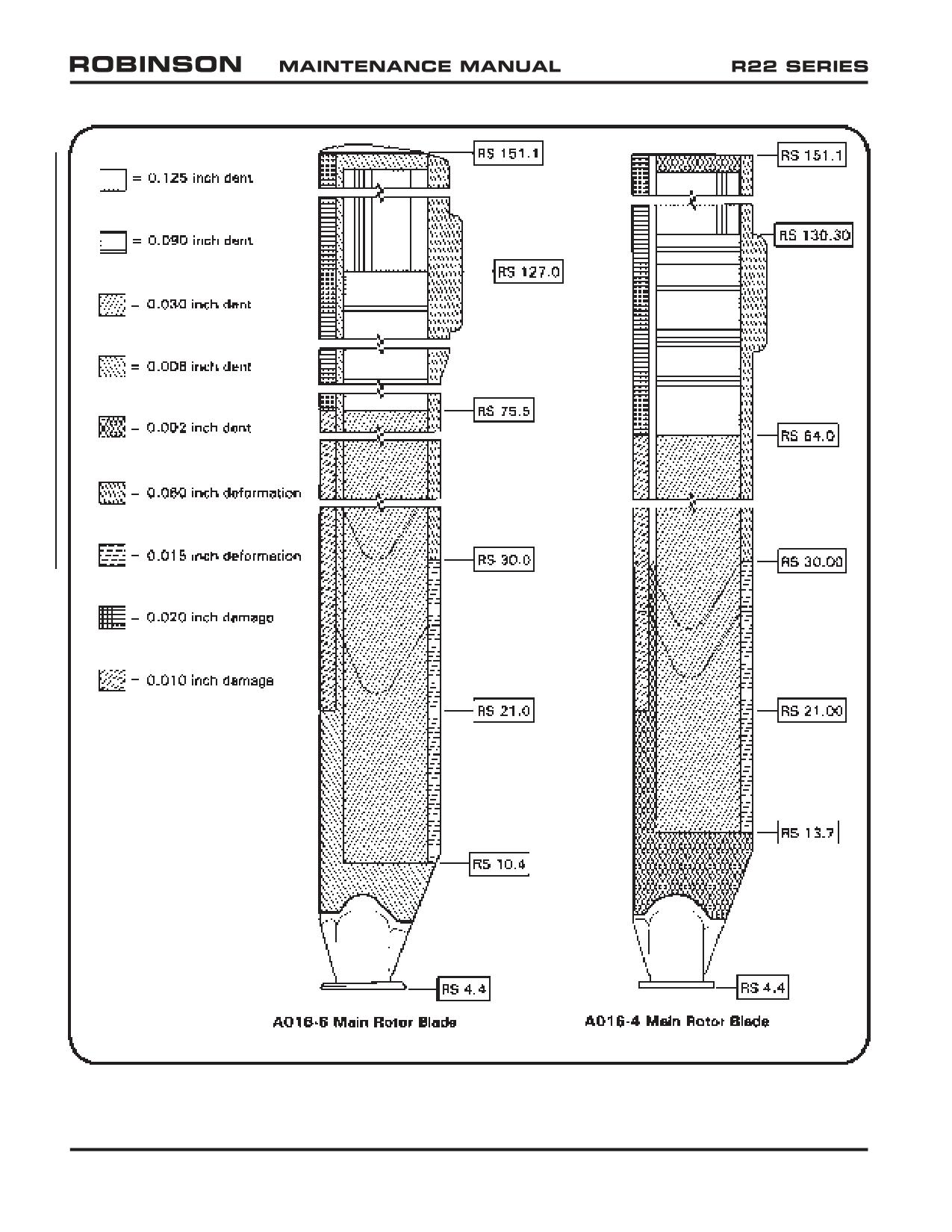
FIGURE 26-12 DENTS AND LOCAL DEFORMATIONS
Page 26.24
Chapter 26 Main Rotor
OCT 2018
26-42 Dents
CAUTION
Tap-test dented areas in honeycomb using an AN970-4 washer or
1965-or-later U.S. quarter dollar coin in good condition. If any voids
are found associated with dents, contact RHC Technical Support.
CAUTION
Do not repair any dent that has a sharp cut or break in the
skin; dent must have 0.060 inch minimum bottom radius. If
necessary, locally penetrant inspect, keeping penetrant materials
away from bond joints.
1. Refer to Figure 26-12. Damage may not exceed the following limits:
a. Honeycomb:
A016-6 Blades:
i.
0.020 inch maximum bulge on opposite side of blade, opposite dent.
ii. 0.125 inch maximum depth dent between RS 127.0 and RS 151.1.
iii. 0.090 inch maximum depth dent between RS 75.5 and RS 127.0.
iv. 0.030 inch maximum depth dent between RS 10.4 and RS 75.5.
A016-4 Blades:
i.
0.020 inch maximum bulge on opposite side of blade, opposite dent.
ii. 0.125 inch maximum depth dent between RS 130.30 and RS 151.1.
iii.0.090 inch maximum depth dent between RS 64.00 and RS 130.30.
iv. 0.030 inch maximum depth dent between RS 13.7 and RS 64.00.
b. Leading edge of doublers:
A016-6 Blades: 0.010 inch maximum depth dent.
c. Supported bond joints:
A016-6 Blades: 0.006 inch maximum depth dent.
A016-4 Blades: 0.002 inch maximum depth dent, tip cap only; refer to SB-103A.
d. Local deformations:
A016-6 Blades: Within 0.75 inch forward of trailing edge:
i.
0.060 inch deformation between RS 30.0 and RS 151.0.
ii. 0.015 inch deformation between RS 10.4 and RS 30.0.
A016-4 Blades: Within 0.75 inch forward of trailing edge:
i.
0.060 inch deformation between RS 30.00 and RS 151.00.
ii. 0.015 inch deformation between RS 13.70 and RS 30.00.
OCT 2018
Chapter 26 Main Rotor
Page 26.25
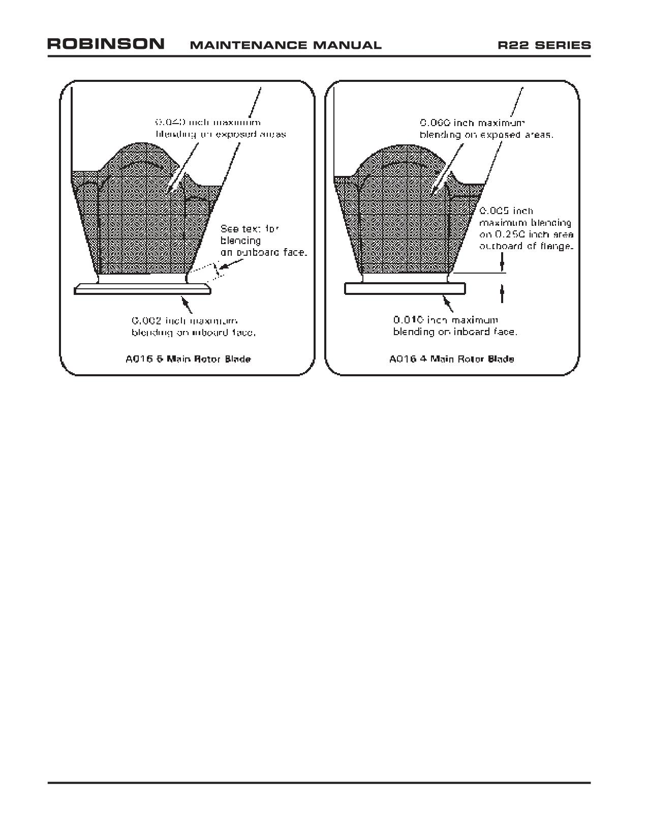
FIGURE 26-13 ROOT FITTING BLEND LIMITS
26-42 Dents (continued)
1. e. Spar: Refer to step 2. Blend damaged areas by hand with a minimum 1.0 inch
blend radius. Blending is not allowed within 0.010 inch of spar groove leading
edge.
A016-6 Blades:
i.
0.020 inch maximum depth damage between RS 75.5 and RS 151.0.
ii. 0.010 inch maximum depth damage between RS 21.0 and RS 75.5.
A016-4 Blades:
i.
0.020 inch maximum depth damage between RS 64.0 and RS 151.0.
ii. 0.010 inch maximum depth damage between RS 21.00 and RS 64.00.
2. Refer to § 26-50 for repair procedures for damage within limits. Smooth, round bottom
dents with 0.060 inch minimum radius may be filled and faired to an aerodynamic
shape.
Page 26.26
Chapter 26 Main Rotor
OCT 2018
26-43 Root Fitting Damage
1. Refer to Figure 26-13. Damage may not exceed the following limits:
A016-6 Blades:
Refer to step 2. Blend damaged areas by hand with a minimum 0.030 inch blend
radius.
a. 0.002 inch maximum depth blending on flange inboard face.
b.
0.005 inch maximum depth, 0.250 inch maximum diameter blending on flange
outboard machined face (3 blends maximum).
0.10 inch minimum distance
from hole edges.
c. 0.040 inch maximum depth blending on exposed areas of root fitting.
A016-4 Blades:
Refer to step 2. Blend damaged areas by hand with a minimum 0.10 inch blend
radius.
a. 0.010 inch maximum depth blending on flange inboard face.
b. 0.005 inch maximum depth blending on 0.250 inch area outboard of flange.
c. 0.060 inch maximum depth blending on exposed areas of root fitting.
2. Refer to § 26-50 for repair procedures for damage within limits.
OCT 2018
Chapter 26 Main Rotor
Page 26.27
FIGURE 26-14 BOND AREAS
Page 26.28
Chapter 26 Main Rotor
OCT 2018
26-44 Voids
WARNING
Voids or debonds in rotor blades are not field repairable. Notify
RHC Technical Support when voids exceeding the limits specified
in the instructions below are found, providing blade serial number,
helicopter serial number, time in service for the rotor blade, and
location and size of the voids that exceed the limits.
CAUTION
Tap-test voids and debonds in blades using an AN970-4 washer
or 1965-or-later U.S. quarter dollar coin in good condition.
A. Critical Bond Areas
Refer to Figure 26-14. Critical bond areas are areas less than 0.50 inch spanwise
and less than 0.30 inch chordwise from the edge of any structural bond joint.
Bond areas not defined as semi-critical or non-critical are considered critical.
Voids separated by less than 0.25 inch are considered continuous.
1. Damage may not exceed the following limits:
a. 0.10 square inch maximum void.
b. Area must be at least 90% bonded.
B. Semi-Critical Bond Areas
A016-6 Blades:
A016-6 Blades do not have semi-critical bond areas.
A016-4 Blades:
Refer to Figure 26-14. Semi-critical bond areas are areas more than 0.50 inch
spanwise or more than 0.30 inch chordwise from the edge of the trim tab.
Voids separated by less than 0.25 inch are considered continuous.
1. Damage may not exceed the following limits:
a. 0.80 inch diameter circle maximum void.
b. 0.90 square inch maximum void.
c. 0.10 square inch maximum of a void extending into a critical bond area.
d. Area must be at least 80% bonded.
OCT 2018
Chapter 26 Main Rotor
Page 26.29
26-44 Voids (continued)
C. Non-Critical Bond Areas
Refer to Figure 26-14. Non-critical bond areas are areas more than 0.50 inch
spanwise or more than 0.30 inch chordwise from B440 cap (A016-4 blades), from
doubler edges, and from bonded areas between skin and honeycomb.
A016-6 Blades:
1. Voids in doubler bond joints separated by less than 0.25 inch are considered
continuous. Damage in doubler bond joints may not exceed the following limits:
a. Area must be at least 80% bonded.
b. 5.0 square inches, 1.0 inch chordwise, & 6.0 inches spanwise max. void.
c. 0.10 square inch maximum of a void extending into a critical bond area.
d. Voids are permissible within 0.30 inch of doubler leading edge where it
wraps around spar and root fitting.
2. Voids in honeycomb bond joints separated by less than 0.50 inch spanwise
or 1.0 inch chordwise are considered continuous. Damage in honeycomb
bond joints may not exceed the following limits:
a. Area must be at least 80% bonded.
b.
8.0 square inches, 1.0 inches chordwise, & 20.0 inches spanwise
maximum void inboard of RS 92.0.
c.
14.0 square inches, 2.0 inches chordwise, & 20.0 inches spanwise
maximum void outboard of RS 92.0.
A016-4 Blades:
1. Voids in A934 doubler bond joints may not exceed the following limits:
a. 5.0 square inches, 1.10 inches chordwise & 6.0 spanwise max. void.
b. 0.10 square inch maximum void extending into a critical bond area.
c. 2.0 inches maximum void from outboard tips (refer to R22 SL-55).
2. Voids in honeycomb bond joints inboard of RS 106.0 may not exceed 8.00
square inches, 1.00 inches chordwise, & 20.00 inches spanwise maximum.
3. Voids in honeycomb bond joints outboard of RS 106.0 may not exceed 14.00
square inches, 2.00 inches chordwise, & 20.00 inches spanwise maximum.
4. Voids in honeycomb bond joints between RS 120.0 and RS 133.5, and
between RS 150.0 and 166.0, must be at least 1.0 inch forward of
honeycomb trailing edge and the skin over void may not move when trim
tabs are flexed.
5. Voids in A934 doubler bond joints separated by less than 0.25 inch, less
than 0.50 inch spanwise, or less than 1.0 inch chordwise are considered
continuous. Area must be at least 80% bonded.
Page 26.30
Chapter 26 Main Rotor
OCT 2018
26-50 Repair of Main Rotor Blades
WARNING
Unauthorized repairs to rotor blades have caused fatal crashes.
CAUTION
Do NOT use power tools or chemical paint strippers to repair
main rotor blades.
NOTE
Refer to § 23-70 for approved materials.
1.
Measure damage per § 26-40.
2.
Remove damage at trailing edges, trim tab edges, tip cap, and/or tip corner by trimming
per § 26-51 as required.
3.
Polish out damage using 220 grit or finer wet-or-dry aluminum-oxide abrasive paper,
and finish with 320 grit or finer wet-or-dry abrasive paper. A fine-toothed file may
be used along the spar and trailing edge, provided the area is finished with 320 grit
or finer wet-or-dry abrasive paper. Sand or file in spanwise direction. Remove only
the material necessary to remove the damage and blend to the radius or dimension
specified. Maintain squareness of trailing edge per Figure 26-16. Visually inspect and
verify damage is removed.
4.
Measure material removed per § 26-40. Verify repair does not exceed limit specified.
5.
Seal or fill as required per the following:
a. Clean area to be sealed or filled using approved solvent (refer to § 23-70).
b. Apply epoxy primer to bond joints with pin holes or other openings. Mix primer
per manufacturer’s instructions. Allow a minimum of 24 hours cure time.
c. Using 220-grit or finer wet-or-dry aluminum-oxide or silicon-carbide abrasive
paper, hand-sand cured adhesive in spanwise direction to a smooth, aerodynamic
finish, congruent with the blade airfoil. Do not remove metal.
d. Hand-sand surrounding painted surface until 25% primer remains. Keep bare
metal to a minimum.
6.
Paint per § 26-52 as required.
7.
Track and balance main rotor per § 10.230 as required.
OCT 2018
Chapter 26 Main Rotor
Page 26.31
FIGURE 26-15 TRIM LIMITS
Page 26.32
Chapter 26 Main Rotor
OCT 2018
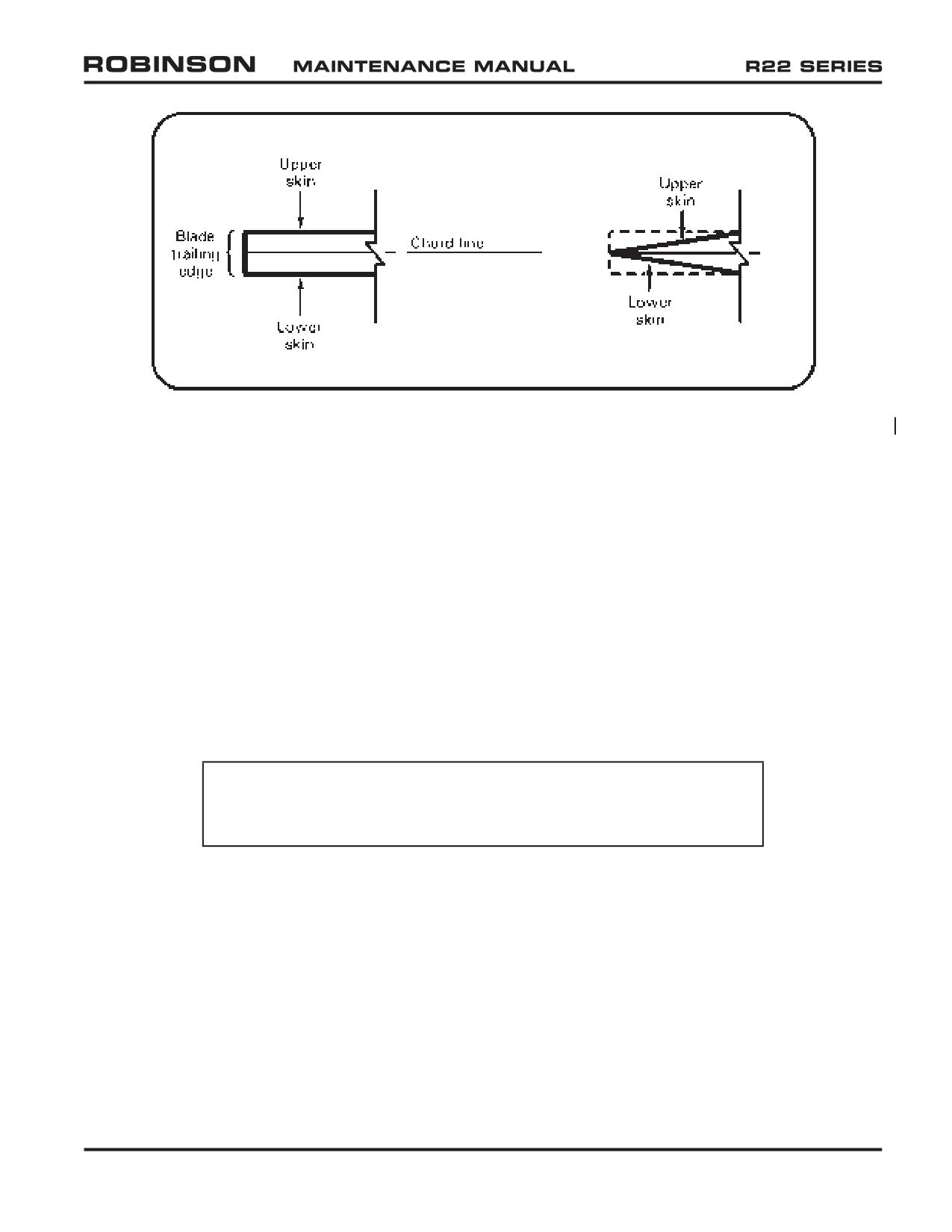
FIGURE 26-16 SANDING/FILING SKIN EDGES SQUARE
26-51 Trimming
Refer to Figures 26-15 & 26-16. Trimming may be performed on the trailing edge of main
rotor blade skins and trim tab edges within limits shown. (Alternately, a trailing edge
nick or notch may be blended out 1.0 inch minimum spanwise, each side of nick or notch
within limits shown.) Trimming is not permitted on spar or doublers.
Tip cap and tip corner may be trimmed within limits shown.
Finish repair per § 26-50 steps 2 thru 7. File trailing edge or trim tab edges square with
skins (do not file into a point). Verify minimum chord dimension.
26-52 Painting
Refer to § 23-70 for approved materials. Refer to paint manufacturer’s recommendations.
CAUTION
If force-drying paint, do not exceed 175º F surface temperature
on blade; monitor blade temperature.
1. Remove main rotor blade tip cover(s) as required. Clean the blade(s).
2. Feather edge of paint bordering bare metal by hand-sanding spanwise with 220-grit or
finer wet-or-dry aluminum-oxide or silicon-carbide abrasive paper. Do not remove metal.
3. Mask area to prevent overspray contamination.
4. Clean bare metal to be painted with a lint-free cloth dampened with enamel cleaner.
5. Prime bare metal, including bare metal under tip cover(s) as required, with at least
two coats epoxy primer. Scuff first coat of primer with 320-grit abrasive paper (or
very fine Scotch-Brite), and wipe down with a lint-free cloth dampened with enamel
cleaner prior to applying second coat.
OCT 2018
Chapter 26 Main Rotor
Page 26.33
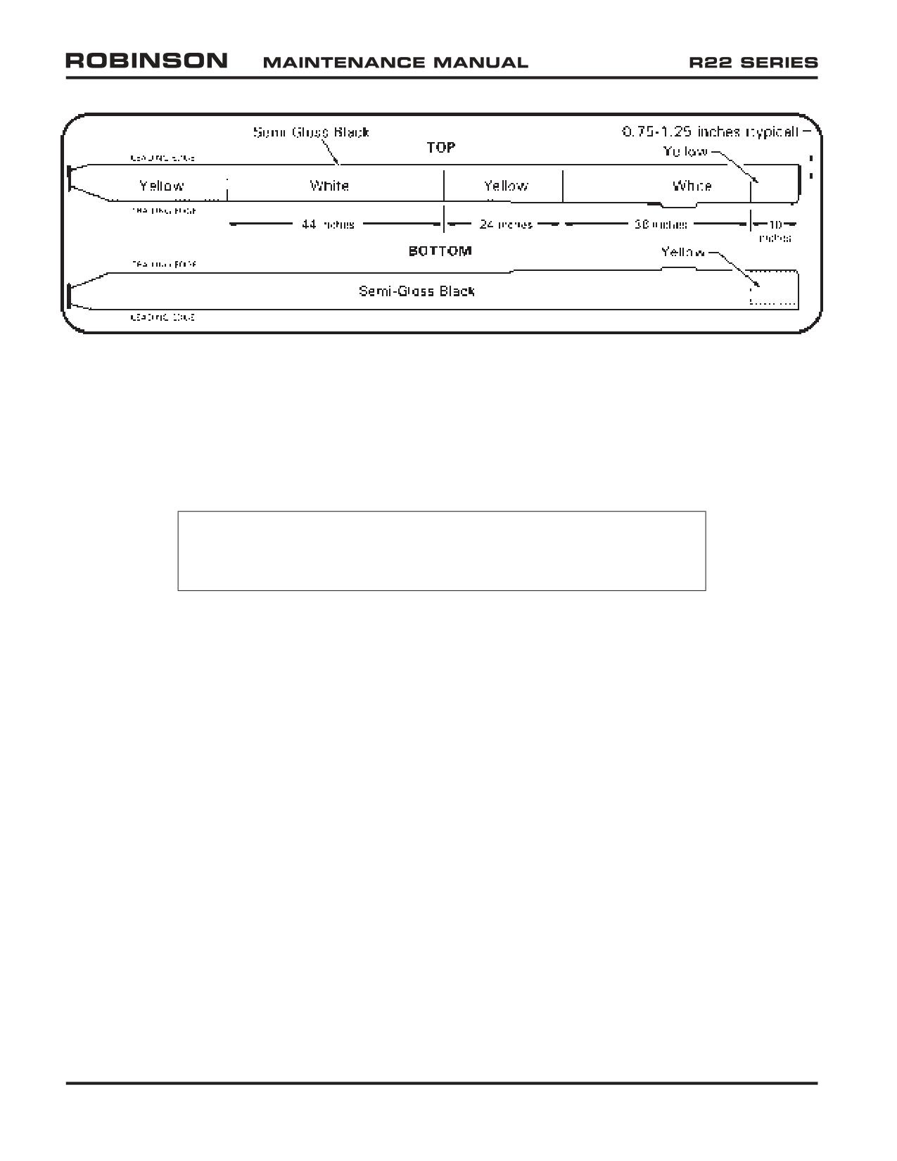
FIGURE 26-17 MAIN ROTOR BLADE PAINT SCHEME (A016-6 BLADE SHOWN)
26-52 Painting (continued)
6. Refer to Figures 26-17. Apply dark gray (root), flat black, white, and/or yellow
polyurethane enamel, as required, to primed area in accordance with paint manufacturer’s
recommendations.
NOTE
Allow Imron paint to cure at least 72 hours before flying in
erosive conditions (such as drizzle, rain, or dust).
7. Install blade tip cover(s) if removed.
8. Remove masking materials.
Page 26.34
Chapter 26 Main Rotor
OCT 2018
CHAPTER 27
MAIN ROTOR DRIVE SYSTEM
Section Title
Page
27-00
Description
27.1
OCT 2018
Chapter 27 Main Rotor Drive System
Page 27.i
Intentionally Blank
Page 27.ii
Chapter 27 Main Rotor Drive System
OCT 2018
CHAPTER 27
MAIN ROTOR DRIVE SYSTEM
27-00 Description
Reserved.
OCT 2018
Chapter 27 Main Rotor Drive System
Page 27.1
Intentionally Blank
Page 27.2
Chapter 27 Main Rotor Drive System
OCT 2018
CHAPTER 28
TAIL ROTOR
Section Title
Page
28-00
Description
28.1
OCT 2018
Chapter 28 Tail Rotor
Page 28.i
Intentionally Blank
Page 28.ii
Chapter 28 Tail Rotor
OCT 2018
CHAPTER 28
TAIL ROTOR
28-00 Description
Reserved.
OCT 2018
Chapter 28 Tail Rotor
Page 28.1
Intentionally Blank
Page 28.2
Chapter 28 Tail Rotor
OCT 2018
CHAPTER 29
TAIL ROTOR DRIVE SYSTEM
Section Title
Page
29-00
Description
29.1
OCT 2018
Chapter 29 Tail Rotor Drive System
Page 29.i
Intentionally Blank
Page 29.ii
Chapter 29 Tail Rotor Drive System
OCT 2018
CHAPTER 29
TAIL ROTOR DRIVE SYSTEM
29-00 Description
Reserved.
OCT 2018
Chapter 29 Tail Rotor Drive System
Page 29.1
Intentionally Blank
Page 29.2
Chapter 29 Tail Rotor Drive System
OCT 2018
CHAPTER 30
ENGINE CONTROLS
Section Title
Page
30-00
Description
30.1
OCT 2018
Chapter 30 Engine Controls
Page 30.i
Intentionally Blank
Page 30.ii
Chapter 30 Engine Controls
OCT 2018
CHAPTER 30
ENGINE CONTROLS
30-00 Description
Reserved.
OCT 2018
Chapter 30 Engine Controls
Page 30.1
Intentionally Blank
Page 30.2
Chapter 30 Engine Controls
OCT 2018
CHAPTER 31
ENGINE OIL SYSTEM
Section Title
Page
31-00
Description
31.1
OCT 2018
Chapter 31 Engine Oil System
Page 31.i
Intentionally Blank
Page 31.ii
Chapter 31 Engine Oil System
OCT 2018
CHAPTER 31
ENGINE OIL SYSTEM
31-00 Description
Reserved.
OCT 2018
Chapter 31 Engine Oil System
Page 31.1
Intentionally Blank
Page 31.2
Chapter 31 Engine Oil System
OCT 2018
CHAPTER 32
POLICE VERSION
Section Title
Page
32-00
Description
32.1
OCT 2018
Chapter 32 Police Version
Page 32.i
Intentionally Blank
Page 32.ii
Chapter 32 Police Version
OCT 2018
CHAPTER 32
POLICE VERSION
32-00 Description
Reserved.
OCT 2018
Chapter 32 Police Version
Page 32.1
Intentionally Blank
Page 32.2
Chapter 32 Police Version
OCT 2018
CHAPTER 33
ELECTRICAL SYSTEM
Section
Title
Page
33-00
Description
33.1
33-10
Battery
33.2
33-20
Clutch Actuator
33.3
33-30
Lighting System
33.3
33-40
Audio System
33.4
33-50
Dual Tachometer
33.5
33-60
Warning and Caution Lights
33.7
33-70
Carbon Monoxide Detector
33.8
33-80
Emergency Locator Transmitter (ELT)
33.9
33-90
Low Rotor RPM Warning System
33.9
33-100 Alternator Output Voltage Adjustment without A942-1
33.10
33-110 Troubleshooting
33.10
33-120 Electrical Load Analysis
33.20
OCT 2018
Chapter 33 Electrical System
Page 33.i
Intentionally Blank
Page 33.ii
Chapter 33 Electrical System
OCT 2018
CHAPTER 33
ELECTRICAL SYSTEM
33-00 Description
CAUTION
The installation of electrical devices can affect the accuracy
and reliability of the electronic tachometer.
A 14-volt DC electrical system which includes an alternator and a sealed lead-acid battery
is standard. The battery is located either in the engine compartment or beneath the
instrument console.
The circuit breaker panel is on the ledge just forward of the left seat. Breakers are marked
to indicate function and amperage and are of the push-to-reset type.
The battery switch controls the battery relay which disconnects the battery from the
electrical system. A wire protected by a fuse near the battery bypasses the battery relay
to allow both tachometers and the clock to continue to receive battery power with the
battery switch off.
The alternator control unit protects the electrical system from overvoltage conditions. The
ammeter indicates current to the battery (“-” indicates discharge). An ALT caution light or
ammeter discharge indication in flight indicates low voltage and possible alternator failure.
NOTE
Except for emergency procedures, do not operate alternator
with battery switched off. The battery helps protect electrical
equipment from voltage spikes.
Later aircraft have an avionics master switch which controls power to the avionics bus.
This allows all avionics to be switched on and off by a single switch.
OCT 2018
Chapter 33 Electrical System
Page 33.1
33-10 Battery
NOTE
Refer to Concorde Battery Corporation's Owner/Operator's
Manual, and Instruction for Continued Airworthiness for battery
maintenance procedures.
CAUTION
To minimize risk of electrical discharge: When disconnecting
battery, disconnect negative (ground) cable from battery first,
then the positive cable. When connecting battery, connect
positive cable to battery first, then the negative (ground) cable.
A. Disconnecting and Removing Battery
1. Turn battery switch off.
a. Aft Battery: Remove engine left side skirt, as required. Remove cotter
rings and wing nuts to release rods attaching battery box assembly to lower
frames. Remove cover.
b. Nose battery: Open upper console and remove battery box cover.
2. Remove hardware securing negative (ground) cable to battery negative terminal.
3. Remove hardware securing positive cable to battery positive terminal. Carefully
remove battery.
B. Installing and Connecting Battery
1. Turn battery switch off.
2. Position battery in battery box and connect battery cables. Special torque terminal
bolts as noted on battery label and torque stripe per Figure 2-1.
3. Install cover.
a. Aft Battery: Install wing nuts and cotter rings to secure rods attaching
battery box assembly to lower frames. Verify security. Install engine left
side skirt, if removed.
b. Nose battery: Secure upper console.
Page 33.2
Chapter 33 Electrical System
OCT 2018
33-20 Clutch Actuator
After the engine is started, it is coupled to the rotor drive system through vee-belts which
are tensioned by raising the upper drive sheave. An electric actuator, located between
the drive sheaves, raises the upper sheave when the pilot engages the clutch switch. The
actuator senses compressive load (belt tension) and switches off when the vee-belts are
properly tensioned. The clutch caution light illuminates whenever the actuator circuit is
energized, either engaging, disengaging, or re-tensioning the belts. The light stays on until
the belts are properly tensioned or completely disengaged.
Belt slack during engine start should be adjusted such that blades begin turning within five
seconds of clutch engagement. Excessive slack may cause belts to jump out of sheave
grooves during start. Periodic readjustment by a mechanic may be required as belts wear
in service.
A fuse located on or near the test switch panel prevents an actuator motor overload from
tripping the circuit breaker. If the fuse blows, the actuator motor will stop but the clutch
caution light will remain illuminated. An open circuit breaker removes power from both the
motor and the light. With an open circuit breaker, no belt tensioning will occur, and the
light will not function to indicate an abnormal condition.
CAUTION
Never take off while clutch caution light is on.
33-30 Lighting System
A red anti-collision light is installed on the tailcone and is controlled by the strobe switch.
Position lights are installed on each side of the cabin and in the tail and are controlled by
the nav lights switch. Post and internal lights (earlier aircraft) or a light at the top of the
windshield (later aircraft) illuminate the instruments. Instrument lighting is active when the
nav lights switch is on and lighting is dimmed via the knob above the nav lights switch.
An overhead map light mounted on a swivel is controlled by an adjacent switch. The map
light may be used for emergency lighting of the instrument panel.
Two landing lights are installed in the nose at different vertical angles to increase the lighted
area. One landing light switch controls both lights and is located on the cyclic center post.
NOTE
Landing lights operate only when clutch actuator switch is in
the engage position.
NOTE
Continuous operation of landing and position lights in flight is
recommended to promote collision avoidance.
OCT 2018
Chapter 33 Electrical System
Page 33.3
33-40 Audio System
A voice-activated intercom/audio system is standard and is controlled by a small control
panel above the avionics stack. The ICS volume knob controls intercom volume but does
not affect radio volume. The VOX squelch knob is used to set the threshold volume at
which the intercom is activated. When the VOX knob is turned fully clockwise, keying
is required to activate the intercom. Later intercom systems include a music input jack
located on the circuit breaker panel. This input is muted when the intercom is active, when
transmitting, and during reception of radio signals.
Headset jacks are located in the ceiling near each seat. The cyclic grips are equipped
with either transmit and intercom buttons or trigger-style intercom/transmit switches. For
the trigger-style switch, the first detent activates the intercom and the second detent
transmits. An additional intercom button is located on the left-hand floor or seat support.
Earlier R22s are equipped with an intercom system that operates in either push-to-talk
(PTT) or hot mic modes. A toggle switch to the left of the cyclic center post is used to
change modes. In PTT mode, the intercom is activated using the intercom buttons.
Audio control panels from several manufacturers are offered as options in place of the
standard intercom system. Pilots should consult the manufacturer’s operating instructions
if an audio panel is installed.
Page 33.4
Chapter 33 Electrical System
OCT 2018
33-50 Dual Tachometer
An electronic engine and rotor dual tachometer is standard. Engine tachometer signal is
provided by magneto breaker points. Rotor tachometer signal is provided by two magnetic
senders at the main gearbox drive yoke. Each tachometer is on a separate circuit with its
own circuit breaker. With battery and alternator switches off, the tachometers continue
to receive power from the battery through a bypass circuit as long as the clutch actuator
switch is in the engage position.
NOTE
Do not stow helicopter with clutch switch engaged. The
tachometers are powered with the clutch engaged and will
discharge the battery.
A. Adjustment
1. The early model A792-1 Dual Tachometer is pre-set at the factory and is not
adjustable in the field. For repair or adjustment, the unit must be returned to
Robinson Helicopter. (No adjustment screw on early models.)
2. The A792-2 Dual Tachometer is pre-set at the factory. Slight variations between
rotorcraft may require readjustment of rotor side of tachometer. To adjust
tachometer:
a. Remove screws that fasten instrument face panel to upper console and
carefully pull panel aft.
b. Ground run helicopter at 104% indication on the engine tachometer. Adjust
the rotor tachometer to read 104%. On back of tachometer, turn the
adjustment screw clockwise to increase and counter-clockwise to decrease
rotor tachometer indication (1/8 turn changes indication approximate 1%).
c. Reinstall instrument panel.
d. If tachometer cannot be adjusted, replace or return to Robinson Helicopter
Company for repair.
OCT 2018
Chapter 33 Electrical System
Page 33.5
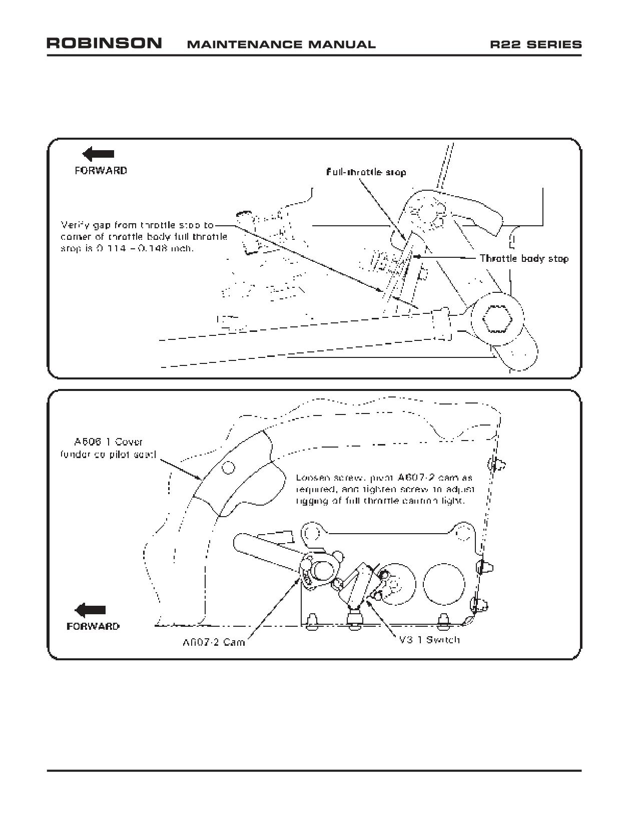
FIGURE 33-1 FULL THROTTLE CAUTION LIGHT RIGGING CHECK
Page 33.6
Chapter 33 Electrical System
OCT 2018
33-60 Warning and Caution Lights
Warning and caution lights include clutch, main gearbox over-temperature, main and tail
gearbox chip, starter on (later aircraft), low fuel, low RPM, alternator, low oil pressure,
rotor brake, governor off, carbon monoxide (aircraft with cabin heater), and full throttle
(later aircraft). The clutch light indicates that the clutch actuator is operating. The low
RPM light and horn indicate rotor RPM at 97% or below. The low oil pressure and low fuel
lights are actuated by sensors in those systems and are independent of the gage indicators.
The alternator light warns of a possible alternator failure. The governor-off light indicates
the RPM governor is switched off.
The main and tail gearbox chip detectors are magnetic devices located in the drain plug of
each gearbox. When metallic particles are drawn to the magnets they close an electrical
circuit, illuminating the caution light. Metal particles may be caused by a failing bearing or
gear, thus giving warning of impending gearbox failure. The main gearbox over-temp light
is actuated by a temperature switch located near the input pinion.
The carbon monoxide light is actuated by a sensor above the pilot’s heater outlet and
indicates elevated cab in carbon monoxide levels.
The full throttle light is activated by a switch in the throttle linkage and indicates that the
engine is near full throttle.
A. Full Throttle Caution Light
1. Rigging Check
a. Turn fuel shut-off valve off.
b. Turn battery switch on. Raise collective full up and slowly rotate twist grip
open until full throttle caution light just illuminates.
c. Refer to Figure 33-1. Verify gap from throttle stop to corner of throttle body
full-throttle stop is 0.114-0.148 inch. Adjust as required per step 2.
d. Lower collective & turn battery switch off. Turn fuel shut-off valve on.
2. Switch Adjustment
a. Refer to Figure 33-1. Raise collective full up, rotate (throttle) twist grip
as required, loosen screw, and pivot A607-2 slotted cam (in throttle
linkage, under co-pilot seat) so V3-1 switch activates when throttle stop
is approximately 0.130 inch from corner of throttle body full-throttle stop.
Tighten screw.
b. Perform rigging check per step 1.
OCT 2018
Chapter 33 Electrical System
Page 33.7
33-70 Carbon Monoxide Detector
The carbon monoxide (CO) detector, if installed, indicates elevated cabin CO levels. CO is
an odorless, toxic gas present in engine exhaust which causes headaches, drowsiness, and
possible loss of consciousness. CO levels may become elevated due to an exhaust leak or
exhaust recirculation during prolonged hovering.
The CO detector system consists of a sensor above the pilot’s heater outlet and a caution
light. A system check (light flashes twice) is performed each time power is switched on.
A sensor malfunction is indicated by a continuing flash every four seconds.
If the caution light illuminates, shut off heater and open nose and door vents as required
to ventilate the cabin. If hovering, land or transition to forward flight. If symptoms of CO
poisoning (headache, drowsiness, dizziness) accompany caution light, land immediately.
Have exhaust system inspected before next flight.
Many chemicals can damage the CO sensor. Avoid use of solvents, detergents, or aerosol
sprays near the sensor. Temporarily tape off openings in top and bottom of sensor housing
when cleaning cabin interior.
Page 33.8
Chapter 33 Electrical System
OCT 2018
33-80 Emergency Locator Transmitter (ELT)
The Emergency Locator Transmitter (ELT) installation consists of a transmitter with internal
battery pack, an external antenna, and a remote switch/annunciator. The transmitter is
mounted to the upper steel tube frame and is accessible through the aft, upper cowl door.
The remote switch/annunciator is located left of the cyclic stick.
The ELT is operated by a switch on the transmitter and a remote switch in the cockpit. The
transmitter switch has been secured in the AUTO or ARM position at installation and should
always be in this position for flight. The remote switch/annunciator is a three position
switch with indicator light. This switch should also be in the AUTO or ARMED (middle)
position for flight. With both switches set to AUTO/ARM, the ELT will begin transmitting
when subjected to a high “G” load. When the unit is transmitting, the red indicator light
illuminates.
Moving the remote switch to ON activates the transmitter. Use the ON position if an
emergency landing is imminent and time permits.
If the ELT is inadvertently activated, use the RESET position of the remote switch to stop
transmission and reset the unit. The red indicator will extinguish when unit is reset.
NOTE
Earlier aircraft may have ELT installations without remote
switch.
For more detailed instructions on ELT operation, maintenance, and required tests, refer to
manufacturer’s instructions supplied with the unit.
33-90 Low Rotor RPM Warning System
A. Horn Adjustment
When the collective is raised 0.2 to 0.4 inches (measured at grip) above fully down, the
low-rotor RPM warning unit must activate the low-rpm warning horn and low-rpm light
at 97% to 96% rotor RPM; horn and light must turn off above 96% to 97% rotor RPM.
The low rotor RPM warning unit is inside the upper console mounted on the left
vertical panel. Some older helicopters may mount the unit on the right side, or
ty-rapped to upper console’s main wire bundle. Adjustments are made by turning an
exposed screw on warning unit, accessible by removing a black-plastic plug from a
3/8-inch diameter hole on the left vertical panel. The A569-1 warning unit’s (potted
circuit board type) adjustment screw sensitivity is approximately 1/16 turn per 1%
change. The A569-5 warning unit’s (metal box type) adjustment screw sensitivity is
approximately 2 turns per 1% change. If warning unit cannot be adjusted to above
values it must be replaced.
OCT 2018
Chapter 33 Electrical System
Page 33.9
33-100 Alternator Output Voltage Adjustment without A942-1
To check or adjust the output voltage:
1. Connect a voltmeter to “I” terminal of voltage regulator and ground with helicopter
running and read voltage (13.2 to 13.8 volts).
2. Output voltage may be adjusted using range screw on voltage regulator.
33-110 Troubleshooting
A. A569-5 Low Rotor RPM Warning Unit
Perform following tests prior to replacing A569-5 low rotor-rpm warning unit:
1.
Verify:
a. Low RPM light bulb is functional.
b. Master switch off.
c. Full-down collective.
d. Horn circuit breaker in.
2.
Access and disconnect both horn and A569-5 low rotor-rpm warning unit from
airframe electrical wiring.
3.
Turn Master switch on and verify Horn circuit breaker remains in. If Horn circuit
breaker pops then -70 wire is shorted to ground; repair as required. Turn Master
switch off.
4.
On the warning unit’s airframe electrical connector, install a jumper between
wires -70 & -75.
5.
Turn Master switch on and verify Horn Start circuit breaker remains in. If Horn
Start circuit breaker pops then a short-to-ground exists in -75 wire and/or collective
activated V3-1 switch; repair as required.
6.
Fully raise collective and verify Horn Start circuit breaker remains in and Low
RPM light illuminates. If Horn Start circuit breaker pops then a short-to-ground
exists in -76 wire and/or -78 wire and/or collective-activated V3-1 switch; repair
as required. If Low RPM light does not illuminate then collective-activated V3-1
switch is faulty or mis-adjusted and/or an open exists in -70, -75, or -76 wires.
7.
Slowly raise and lower collective fully several times while simultaneously
manipulating throttle. Verify Horn Start circuit breaker remains in and Low RPM
light remains illuminated whenever collective is raised. If Horn Start circuit breaker
pops then a short-to-ground condition is occurring in -70, -75, or -76 wires and/or
collective-activated V3-1 switch due to collective movement. Check for pinched/
rubbing wiring and repair as required.
8.
Turn Master switch off. Connect horn to airframe wiring.
Page 33.10
Chapter 33 Electrical System
OCT 2018
33-110 Troubleshooting (continued)
A. A569-5 Low Rotor RPM Warning Unit (continued)
9.
Turn Master switch on. Raise collective and verify horn activates and has
consistent tone. If Horn Start circuit breaker pops then horn is faulty and/or -78
wire is shorted to ground; repair as required. If horn fails to activate then -79
wire is open or horn is faulty; repair as required. If tone is inconsistent then horn
is faulty and/or poor connections exist; repair as required.
10.
If A569-5 warning unit has starter lockout circuit enabled (warning unit’s 9-pin
connector plugged into airframe harness), also perform following steps:
11.
Check A999-1 master radio relay current draw:
a. Master switch off and belt tension actuator fully disengaged.
b. Disconnect A569-5 low-rpm warning unit’s 9-pin connector and place an
ammeter in series (positive lead on pin 7) between pins 7 and 8 on airframe
side of connector.
c. Master switch on, Horn Start and Clutch Start circuit breakers in, avionics
off, rotor brake released, mixture at idle cut-off.
d. Select key switch to Start position and crank engine. Note and record
current draw at ammeter while cranking engine. Select key switch to Off
position.
e. Disconnect 582 wire at tab on starter solenoid and isolate connector (do not
let it ground). Select key switch to Start position. Note and record current
draw at ammeter; current should be 94-156 milliamps and a buzzing sound
should be heard from the starter vibrator. Select key switch to Off position.
12.
Check starter circuit:
a. Master switch off and belt tension actuator fully disengaged.
b. Disconnect A569-5 low-rpm warning unit’s 9-pin connector and jump pins 7
and 8 on airframe side of connector.
c. Master switch on, Horn Start and Clutch Start circuit breakers in, rotor brake
released, mixture at idle cut-off.
d. Select key switch to Start position and crank engine. If engine does not
crank there is a problem in the starter circuit. If engine cranks then there is
a problem in either the A569-5 unit or the sense circuit.
OCT 2018
Chapter 33 Electrical System
Page 33.11
33-110 Troubleshooting (continued)
A. A569-5 Low Rotor RPM Warning Unit (continued)
13. Check A596-5 sense circuit:
a. Master Switch on.
b. Momentarily engage clutch and verify Clutch light illuminates then disengage
clutch completely.
c. Master switch off.
d. Disconnect A051-1 actuator’s black four-pin connector. Ground airframe-
side plug’s pin 1 thru a #330 (post light type) lamp.
CAUTION
Failure to ground pin 1 thru a #330 lamp (such as direct
grounding) may result in wiring damage.
e. Verify less than 200 ohms (20 ohm nominal) to ground at pin 4 and at pin 5
on ship side of A569-5’s 9-pin connector.
f. Master switch on.
g. With A569-5 unit connected to airframe harness, verify voltage does not
exceed 0.5V from pin 4 to ground and from pin 5 to ground.
h. Master switch on, Horn Start and Clutch Start circuit breakers in, rotor brake
released, mixture at idle cut-off.
i. Select key switch to Start position and crank engine. Failure of engine to
crank indicates problem in A569-5 unit.
14. Upon successful completion of preceding tests the A569-5 low rotor-rpm warning
unit may be replaced and adjusted per § 33-90.
Page 33.12
Chapter 33 Electrical System
OCT 2018
33-110 Troubleshooting (continued)
B. General
TROUBLE
PROBABLE CAUSE
CORRECTION
No electrical
Battery terminals corroded
Clean terminals.
power
Bad or no ground
Clean ground path.
Tripped circuit breaker
Check circuit, if circuit checks ok, reset
circuit breaker.
Low battery voltage
Check battery. Recharge if necessary.
Low or no alternator output
Check alternator belt tension, wiring, and
alternator control unit.
Bad wire or terminal
Replace.
Engine cranks
Low battery voltage
Service or replace battery.
slowly, but will
not start
Insufficient drive belt deflection
Adjust actuator down-limit screw.
Corroded or dirty battery or starter
Clean terminals.
terminals
Bad starter relay, wires or terminals
Replace defective parts.
Engine cranks
Bad ignition switch
Replace switch.
but will not start
Bad starting vibrator
Repair or replace vibrator.
Incorrect retard timing
Adjust retard magneto internal timing.
Starter fails to
Rotor brake engaged
Release rotor brake.
operate
Low battery charge
Check and recharge if necessary.
Circuit breakers tripped
Reset both HORN START and CLUTCH
START circuit breakers.
Actuator not fully disengaged
Engage actuator momentarily, then fully
disengage.
Loose connections
Check all wiring (refer to wiring diagram).
Defective wiring
Check all wiring (refer to wiring diagram).
Starter motor - burned winding or
Repair or replace starter.
bad brushes
OCT 2018
Chapter 33 Electrical System
Page 33.13
33-110 Troubleshooting (continued)
B. General (continued)
TROUBLE
PROBABLE CAUSE
CORRECTION
Discharged battery
Battery worn out
Replace
Charging rate not set correctly
Reset
Standing too long
Remove and recharge battery
Equipment left on accidentally
Remove and recharge battery
Starter - Low cranking speed
Same electrical causes as listed
Same remedies as listed under
under “starter fails to operate”
”starter fails to operate”
Battery life is short
Impurities in electrolyte
Replace battery
Low charging rate
Adjust voltage regulator
Battery runs out of electrolyte
Too much water added to battery
Drain and keep battery at proper
and charging rate too high
level and adjust voltage regulator
Excessive corrosion inside
Spillage from overfilling
Use care in adding water
container
Vent lines leaking or clogged
Repair or clean
Charging rate too high
Adjust voltage regulator
Battery consumes excessive
Charging rate too high (if in all
Correct charging rate
water
cells)
Alternator fails to supply
Alternator defective
Replace
charging current with engine
operating
Voltage regulator defective
Replace
Overvoltage relay defective
Replace
Alternator switch defective
Replace
Page 33.14
Chapter 33 Electrical System
OCT 2018