Helicopter Bell-212. MAINTENANCE MANUAL (2021) - page 4
BHT-212-MM-1
SPECIAL INSPECTIONS
5-38.
EACH 600 HOURS OF TRANSMISSION OPERATION
INITIAL
DATA REFERENCE
INSPECTION TASK DESCRIPTION
MECH OTHER
DATE:
__________________
W.O.
_____________________
FACILITY:
_________________________________________
HELICOPTER S/N:
__________________________________
REGISTRY NO.:
____________________________________
TOTAL TIME:_______________________________________
SIGNATURE:_______________________________________
NOTE
Accomplish each
600 hours inspection of
transmission operation.
TRANSMISSION ASSEMBLY 212-040-001-115, -119, -123,
AND -127
- Inspect
1.
Remove input pinion quill assembly and No. 2 hydraulic
pump drive quill from transmission main case. Dimensionally
inspect input pinion quill bore diameter of main case for
out-of-round condition. Input quill bore shall be 6.7521 inches
(171.5033 mm) and maximum out-of-round condition (maximum
diameter - minimum diameter) shall be 0.0030 inch (0.0762
mm). Replace case assembly if bore diameter exceeds
maximum conditions. Dimensionally inspect No. 2 hydraulic
pump quill bore of main case assembly for out-of-round
condition. Hydraulic drive quill bore maximum diameter shall be
5.0021 inches
(127.05 mm) and maximum out-of-round
condition shall be 0.0030 inch (0.0762 mm). Replace case
assembly if bore diameter exceeds maximum conditions.
5-00-00
Export Classification C, ECCN EAR99
26 JUN 2013 Rev. 14
Page 157
BHT-212-MM-1
SPECIAL INSPECTIONS
5-38.
EACH 600 HOURS OF TRANSMISSION OPERATION (CONT)
INITIAL
DATA REFERENCE
INSPECTION TASK DESCRIPTION
MECH OTHER
2.
Disassemble input pinion quill assembly sufficiently to
ascertain whether triplex ball bearing outer races have rotated
in sleeve. Note if etched V markings are still aligned. If bearing
outer races have rotated, complete the disassembly of quill.
Dimensionally inspect sleeve bore. If dimension is 5.51 inches
(139.95 mm) or greater, replacement is required. Dimensionally
inspect bearing outer diameter. If dimension is 5.51 inches
(139.95 mm) or less, replacement is required.
3.
Inspect main input driven spiral bevel gear P/N
204-040-701-003 as follows:
a. Utilizing transmission case input quill port, inspect all 62
teeth of the main input driven spiral bevel gear convex side for
unsatisfactory conditions such as scoring, hard lines, nicks,
dents, chipping, metal deformation, etc.
NOTE
Inspection mirrors and a suitable light are required.
Turn rotor slowly to permit inspection of all gear
teeth.
b. Inspect concave side of all 62 teeth. Refer to Figure 5-6
for unacceptable conditions on concave side.
BHT-212-CR&O
c. Remove and replace any gear that does not meet
inspection requirements.
5-00-00
Page 158
Rev. 14
26 JUN 2013
Export Classification C, ECCN EAR99
BHT-212-MM-1
SPECIAL INSPECTIONS
5-39.
600 HOURS/12 MONTHS OF TAIL ROTOR DRIVESHAFT COUPLING OPERATION
INITIAL
DATA REFERENCE
INSPECTION TASK DESCRIPTION
MECH OTHER
DATE:
__________________
W.O.
_____________________
FACILITY:
_________________________________________
HELICOPTER S/N:
__________________________________
REGISTRY NO.:
____________________________________
TOTAL TIME:_______________________________________
SIGNATURE:
_______________________________________
NOTE
Accomplish each 600 hours of component operation
or
12
months,
whichever
occurs
first.
No Non-Destructive Inspection (NDI) required.
BHT-212-CR&O
TAIL ROTOR DRIVESHAFT COUPLINGS
Chapter 65
1.
Remove tail rotor driveshaft assemblies.
NOTE
Disassemble flexible couplings only to the extent
necessary to remove old grease and repack.
2.
Clean, visually inspect, and repack tail rotor hanger
assembly flexible couplings.
3.
Clean, visually inspect, and repack intermediate gearbox
flexible couplings.
4.
Clean, visually inspect, and repack tail rotor gearbox
flexible coupling.
5.
Clean, visually inspect, and repack transmission tail rotor
driveshaft flexible coupling.
6.
Install tail rotor driveshaft assemblies.
5-00-00
Export Classification C, ECCN EAR99
15 MAY 2020 Rev. 18
Page 159/160
BHT-212-MM-1
SPECIAL INSPECTIONS
5-40.
600 HOURS/12 MONTHS OF MAIN DRIVESHAFT OPERATION
INITIAL
DATA REFERENCE
INSPECTION TASK DESCRIPTION
MECH OTHER
DATE:
__________________
W.O.
_____________________
FACILITY:
_________________________________________
HELICOPTER S/N:
__________________________________
REGISTRY NO.:
____________________________________
TOTAL TIME:_______________________________________
SIGNATURE:_______________________________________
NOTE
Accomplish each 600 hours or 12 months of main
driveshaft operation, whichever occurs first. No
Non-Destructive Inspection (NDI) required.
MAIN DRIVESHAFT 212-040-005-003, -007, AND -103
Chapter 63
1.
Remove main driveshaft.
NOTE
Disassemble driveshaft only to the extent necessary
to remove old grease and repack.
BHT-212-CR&O
2.
Clean, visually inspect, and repack flexible couplings.
3.
Install main driveshaft.
5-00-00
Export Classification C, ECCN EAR99
26 JUN 2013 Rev. 14
Page 161/162
BHT-212-MM-1
SPECIAL INSPECTIONS
5-40A. EACH 600 HOURS/12 MONTHS INSPECTION OF MAGNETIC BRAKE ASSEMBLY
INITIAL
DATA REFERENCE
INSPECTION TASK DESCRIPTION
MECH OTHER
DATE:
__________________
W.O.
_____________________
FACILITY:
_________________________________________
HELICOPTER S/N:
__________________________________
REGISTRY NO.:
____________________________________
TOTAL TIME:_______________________________________
SIGNATURE:_______________________________________
NOTE
Accomplish the following inspection each 600 hours
or 12 months, whichever occurs first.
The following inspection is not required for
helicopters equipped with IFR Kit P/N 212-706-106.
MAGNETIC BRAKE ASSEMBLY P/N 204-001-376-003
ASB 212-17-157
1.
Perform a detailed visual inspection of the magnetic brake
assembly in accordance with ASB 212-17-157.
2.
If the mechanical damage exceeds the limitation, contact
Product Support Engineering.
5-00-00
Export Classification C, ECCN EAR99
15 NOV 2018 Rev. 16
Page 162A/162B
BHT-212-MM-1
SPECIAL INSPECTIONS
5-40B. EACH 600 HOURS/12 MONTHS INSPECTION OF FIRE EXTINGUISHER DISCHARGE
TUBES
INITIAL
DATA REFERENCE
INSPECTION TASK DESCRIPTION
MECH OTHER
DATE:
__________________
W.O.
_____________________
FACILITY:
_________________________________________
HELICOPTER S/N:
__________________________________
REGISTRY NO.:
____________________________________
TOTAL TIME:_______________________________________
SIGNATURE:_______________________________________
NOTE
Accomplish the following inspection each 600 hours
or 12 months, whichever occurs first.
The following inspection is not required if the
discharge
tubes
212-060-921-101
and
212-060-921-102 are installed in accordance with
ASB 212-12-146.
FIRE EXTINGUISHER DISCHARGE TUBES P/N
212-060-921-001FM AND -002FM
ASB 212-12-146
1.
Visually inspect the loop clamp AN735C16 installed on
discharge tubes 212-060-921-001FM and 212-060-921-002FM
for condition and security.
5-00-00
Export Classification C, ECCN EAR99
15 NOV 2018 Rev. 16
Page 162C/162D
BHT-212-MM-1
SPECIAL INSPECTIONS
5-41.
EACH 1000 HOURS OF COMPONENT OPERATION
INITIAL
DATA REFERENCE
INSPECTION TASK DESCRIPTION
MECH OTHER
DATE:
__________________
W.O.
_____________________
FACILITY:
_________________________________________
HELICOPTER S/N:
__________________________________
REGISTRY NO.:
____________________________________
TOTAL TIME:_______________________________________
SIGNATURE:_______________________________________
NOTE
Accomplish each
1000 hours of component
operation.
Chapter 29
HYDRAULIC ACCUMULATORS
1.
Remove hydraulic accumulators.
BHT-212-CR&O
2.
Disassemble, clean, and visually inspect for corrosion and
damage.
3.
Replace any unserviceable parts.
4.
Reassemble hydraulic accumulators.
Chapter 29
5.
Install hydraulic accumulators.
Chapter 79
OIL COOLER BLOWERS
1.
Remove oil cooler blowers.
BHT-212-CR&O
2.
Disassemble, clean, and visually inspect for corrosion and
damage.
3.
Replace bearings and any other unserviceable parts.
4.
Reassemble oil cooler blowers.
5-00-00
Export Classification C, ECCN EAR99
26 JUN 2013 Rev. 14
Page 163
BHT-212-MM-1
SPECIAL INSPECTIONS
5-41.
EACH 1000 HOURS OF COMPONENT OPERATION (CONT)
INITIAL
DATA REFERENCE
INSPECTION TASK DESCRIPTION
MECH OTHER
Chapter 79
5.
Install oil cooler blowers.
5-00-00
Page 164
Rev. 14
26 JUN 2013
Export Classification C, ECCN EAR99
BHT-212-MM-1
SPECIAL INSPECTIONS
5-42.
FIRST 1000 HOURS OF COMPONENT TIME AND EACH 3000 HOURS THEREAFTER OF
COMPONENT TIME
INITIAL
DATA REFERENCE
INSPECTION TASK DESCRIPTION
MECH OTHER
DATE:
__________________
W.O.
_____________________
FACILITY:
_________________________________________
HELICOPTER S/N:
__________________________________
REGISTRY NO.:
____________________________________
TOTAL TIME:_______________________________________
SIGNATURE:_______________________________________
NOTE
Accomplish first 1000 hours inspection of component
time and each 3000 hours thereafter of component
time.
Applicable to flight control tube assemblies: 204-001-957-001,
205-001-017-001/-007,
212-001-051-001,
212-001-060-001,
and
212-076-151-001/-003/-005/-007/-009/-011. Supersedes
ASB 212-76-6.
ASB 212-76-6
Flight Control Tube Assemblies are identified by the following
sub-assemblies:
204-001-957-001 contains tube assembly 204-001-957-003
205-001-017-001 contains tube assembly 205-001-017-003
205-001-017-007 contains tube assembly 205-001-017-009
212-001-051-001 contains tube assembly 212-001-051-005
212-001-060-001 contains tube assembly 212-001-060-003
212-076-151-005 contains tube assembly 212-076-150-005
212-076-151-007 contains tube assembly 212-001-275-001
212-076-151-007 contains tube assembly 212-001-280-101
1
212-076-151-009 contains tube assembly 212-001-275-003
212-076-151-009 contains tube assembly 212-001-280-103
1
212-076-151-011 contains tube assembly 212-001-275-005
212-076-151-011 contains tube assembly 212-001-280-105
1
Control tube assemblies 212-001-280-101/-103/-105 are
1
fabricated from corrosion Resistant Steel (CRES),
special inspection not applicable.
5-00-00
Export Classification C, ECCN EAR99
26 JUN 2013 Rev. 14
Page 165
BHT-212-MM-1
SPECIAL INSPECTIONS
5-42.
FIRST 1000 HOURS OF COMPONENT TIME AND EACH 3000 HOURS THEREAFTER OF
COMPONENT TIME (CONT)
INITIAL
DATA REFERENCE
INSPECTION TASK DESCRIPTION
MECH OTHER
1.
Inspect
flight
control
tube
assemblies
P/N
212-076-151-001/-003/-005/-007/-009/-011 as follows:
a. Measure and record overall length of control tube, and
then remove adjustable clevis.
BHT-212-CR&O
b. Inspect control rube for internal corrosion using a
borescope or equivalent. (Paint removal is not necessary.)
Particular attention shall be given to threaded areas. Any paint
anomalies such as blistering or discoloration will require paint
removal and further inspection. Any sighted internal corrosion is
cause for control tube rejection. If serviceable, refinish internal
surface of control tube with two coats of lacquer (C-226) using
fill and drain method.
c. Visually inspect external surfaces of control tubes for
mechanical damage and/or corrosion. Refer to the
BHT-212-CR&O manual for limits.
d. If serviceable, coat the control tube threaded area with
corrosion preventive compound (C-101), reinstall clevis into
control tube and adjust to recorded length.
2.
Inspect P/N 204-001-957-001, 205-001-017-001 and -007,
212-001-051-001, 212-001-060-001 control tubes as follows:
a. Using a suitable container filled with 135 to 155°F (57 to
68°C) water, fully immerse the control tube for 2 minutes.
b. Any air bubbles detected from the control tube as a
result of the water immersion is cause for rejection of the tube.
c. Provided no air bubbles are detected, the control tube
may be considered serviceable.
3.
Install flight control tubes and check rigging.
5-00-00
Page 166
Rev. 14
26 JUN 2013
Export Classification C, ECCN EAR99
BHT-212-MM-1
SPECIAL INSPECTIONS
5-42.
FIRST 1000 HOURS OF COMPONENT TIME AND EACH 3000 HOURS THEREAFTER OF
COMPONENT TIME (CONT)
INITIAL
DATA REFERENCE
INSPECTION TASK DESCRIPTION
MECH OTHER
Chapter 67
ELEVATORS
- Inspect
1.
Remove and Inspect elevators as follows:
BHT-212-CR&O
a. Remove both elevators and inspect condition of ears on
elevator horn 205-001-914 and mating ears on elevator attach
fitting 205-030-475. Inspect ears by dye penetrant method.
Replace horn or fitting if any cracks are evident.
BHT-212-CR&O
b. Inspect elevators for general condition, cracks, and
corrosion. Repair inboard rib if any cracks exist. The inboard rib
shall be replaced if any cracks extend into rib flange.
5-00-00
Export Classification C, ECCN EAR99
26 JUN 2013 Rev. 14
Page 167/168
BHT-212-MM-1
SPECIAL INSPECTIONS
5-43.
EACH 1000 HOURS/12 MONTHS OF MAIN ROTOR BLADE OPERATION
INITIAL
DATA REFERENCE
INSPECTION TASK DESCRIPTION
MECH OTHER
DATE:
__________________
W.O.
_____________________
FACILITY:
_________________________________________
HELICOPTER S/N:
__________________________________
REGISTRY NO.:
____________________________________
TOTAL TIME:_______________________________________
SIGNATURE:_______________________________________
NOTE
Accomplish each 1000 hours or 12 months of main
rotor blade operation, whichever occurs first.
Chapter 62
MAIN ROTOR BLADES
- Clean and Inspect
1.
Clean blade from an area starting at butt end of blade to
several inches outboard of doublers on both upper and lower
surfaces, using aliphatic naphtha (C-305) or equivalent.
NOTE
Inspection may be accomplished with blades
installed on main rotor hub assembly.
BHT-212-CR&O
2.
Inspect main rotor blade grip pads, grip plates, doublers,
drag plates, and adjacent surfaces for voids, edge voids,
corrosion, cracks, and condition of adhesive squeeze-out along
bond lines. Refer to BHT-212-CR&O manual for inspection
criteria and repair limits.
5-00-00
Export Classification C, ECCN EAR99
26 JUN 2013 Rev. 14
Page 169/170
BHT-212-MM-1
SPECIAL INSPECTIONS
5-44.
EACH 1200 HOURS/24 MONTHS OF COMPONENT OPERATION
INITIAL
DATA REFERENCE
INSPECTION TASK DESCRIPTION
MECH OTHER
DATE:
__________________
W.O.
_____________________
FACILITY:
_________________________________________
HELICOPTER S/N:
__________________________________
REGISTRY NO.:
____________________________________
TOTAL TIME:_______________________________________
SIGNATURE:_______________________________________
NOTE
Accomplish each 1200 hours or 24 months of listed
component operation, whichever occurs first.
ASB 212-02-117
MAIN ROTOR HUB PINS 204-012-104-003/-005 AND
ASB 212-10-142
INBOARD STRAP FITTINGS 212-010-103-005/-007/-105
BHT-212-CR&O
1.
Remove the four pins and two inboard strap fittings from
the main rotor hub assembly.
1A. Do a detailed visual inspection of all the surfaces of the
strap pin for mechanical or corrosion damage with a 10X
magnifying glass.
1B. If mechanical damage or corrosion pitting is found on a
strap pin, discard the pin.
2.
Inspect pins and inboard strap fittings by magnetic particle
method.
3.
Magnetic particle indication interpreted as cracks are not
acceptable and the pin or inboard strap fitting must be
discarded.
4.
If strap pins are found cracked, the mating strap fitting must
also be discarded.
5-00-00
Export Classification C, ECCN EAR99
15 JUL 2021 Rev. 19
Page 171
BHT-212-MM-1
SPECIAL INSPECTIONS
5-44.
EACH 1200 HOURS/24 MONTHS OF COMPONENT OPERATION (CONT)
INITIAL
DATA REFERENCE
INSPECTION TASK DESCRIPTION
MECH OTHER
5.
If the pins are replaced (e.g., time expired), the mating
fittings will be considered serviceable only after NDI inspection
of the removed pins has confirmed they are not cracked.
6.
Reassemble main rotor hub assembly.
7.
Make an entry in the helicopter Historical Records (HR) to
show that the main rotor hub pins and inboard strap fittings have
been inspected in accordance with this special inspection.
MAIN ROTOR YOKE 212-011-102-ALL
- Detailed Visual Inspection
BHT 212-CR&O
1.
Remove bearing races and spacers.
ASB 212-94-94
NOTE
Shield
204-012-116-107 does not need to be
removed to accomplish the inspection procedure.
2.
Inspect yoke spindle for cracks and corrosion pits.
3.
Inspect yoke spindle bearing journals for wear.
4.
Any crack or wear beyond limits is cause for rejection of
the yoke. Remove any corrosion.
5.
Assemble yoke.
ASB 212-90-59
MAIN ROTOR DRAG BRACE 204-011-140-ALL
- Inspect
BHT-212-CR&O
1.
Remove drag brace assemblies.
2.
Inspect drag brace assemblies for corrosion and
mechanical damage.
BHT-ALL-SPM
3.
Perform a magnetic particle inspection.
4.
Install drag brace assemblies.
5-00-00
Page 172
Rev. 18
15 MAY 2020
Export Classification C, ECCN EAR99
BHT-212-MM-1
SPECIAL INSPECTIONS
5-44.
EACH 1200 HOURS/24 MONTHS OF COMPONENT OPERATION (CONT)
INITIAL
DATA REFERENCE
INSPECTION TASK DESCRIPTION
MECH OTHER
BHT-212-CR&O
MAIN ROTOR HUB GRIP 204-011-121-ALL
- Detailed Visual Inspection
1.
Prepare both main rotor grip tangs for inspection by
cleaning exposed surfaces with denatured alcohol (C-326) as
per BHT-ALL-SPM. Wipe dry.
2.
Inspect grip surfaces for evidence of hairline cracks on
upper and lower tangs exposed surfaces. Pay particular
attention to the lower tang lower surface from the blade bolt
bushing flange to the trailing and leading edge of the tang.
Crack indication requires the grip to be removed from service
for further evaluation (Figure 5-7).
3.
For main rotor grip 204-011-121-009, inspect grip barrels
both leading and trailing sides for evidence of hairline cracks
(Figure 5-7).
4.
Check for gap (360°) between flange of blade bolt bushing
and surface of grip tang. Maximum gap of
0.0025 inch
(0.0635 mm) permitted. Noted gap greater than the maximum
permitted requires bushing to be replaced.
5.
Fit a blade bolt through both bushings simultaneously, bolt
should be able to be turned with the fingers. If this cannot be
accomplished, refer to BHT-212-CR&O, Chapter 62 for further
inspection requirements.
6.
Inspect buffer pads on tang inner surfaces for
delamination. Any delamination will require buffer pad
replacement (Figure 5-7).
5-00-00
Export Classification C, ECCN EAR99
15 MAY 2020 Rev. 18
Page 173
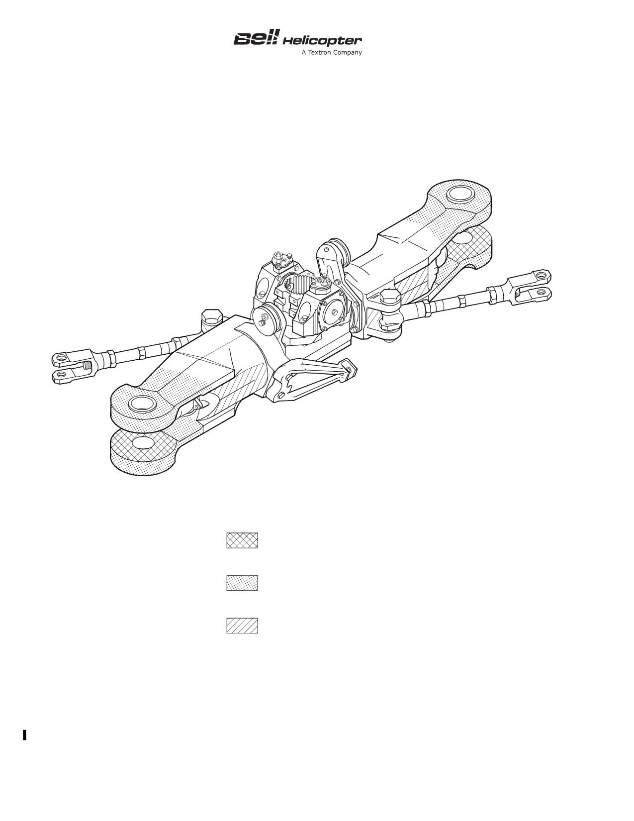
BHT-212-MM-1
GRIP (204-011-121)
INSPECT BUFFER PAD
FOR DELAMINATION (IF
INSTALLED)
AREA TO BE INSPECTED
UPPER AND LOWER TANGS
ALL EXPOSED SURFACES
AREA TO BE INSPECTED
GRIP BARREL LEADING
AND TRAILING SIDES
EXPOSED SURFACE (-009
GRIP ONLY)
212_MM_05_0007
Figure 5-7. Inspection of Main Rotor Hub Grip (1200 Hours/24 Months)
5-00-00
Page 174
Rev. 14
26 JUN 2013
Export Classification C, ECCN EAR99
BHT-212-MM-1
SPECIAL INSPECTIONS
5-45.
EACH 1200 HOURS OF MAIN ROTOR HUB PIN OPERATION - DELETED
INITIAL
DATA REFERENCE
INSPECTION TASK DESCRIPTION
MECH OTHER
NOTE
The Each
1200 Hours of Main Rotor Hub Pin
Operation special inspection has been moved to the
1200 Hour/24 Months of Component Operation
special inspection.
5-00-00
Export Classification C, ECCN EAR99
26 JUN 2013 Rev. 14
Page 175/176
BHT-212-MM-1
SPECIAL INSPECTIONS
5-45A. EVERY
12 MONTHS/2500 LANDINGS HIGH FORWARD CROSSTUBE DEFLECTION
CHECK
INITIAL
DATA REFERENCE
INSPECTION TASK DESCRIPTION
MECH OTHER
DATE:
__________________
W.O.
_____________________
FACILITY:
_________________________________________
HELICOPTER S/N:
__________________________________
REGISTRY NO.:
____________________________________
TOTAL TIME:_______________________________________
SIGNATURE:_______________________________________
NOTE
Accomplish the deflection check of the High Forward
Crosstubes assemblies
205-050-403-031 and
412-050-046-101 at every
12 months or
2500
landings, whichever occurs first.
HIGH FORWARD CROSSTUBES 205-050-403-031 AND
412-050-046-101
ASB 212-10-140
1.
Carry out the deflection check of the High Forward
Crosstubes in accordance with ASB 212-10-140.
5-00-00
Export Classification C, ECCN EAR99
15 NOV 2018 Rev. 16
Page 176A/176B
BHT-212-MM-1
SPECIAL INSPECTIONS
5-45B. EVERY 12 MONTHS/5000 LANDINGS HIGH FORWARD CROSSTUBE FLUORESCENT
PENETRANT INSPECTION
INITIAL
DATA REFERENCE
INSPECTION TASK DESCRIPTION
MECH OTHER
DATE:
__________________
W.O.
_____________________
FACILITY:
_________________________________________
HELICOPTER S/N:
__________________________________
REGISTRY NO.:
____________________________________
TOTAL TIME:_______________________________________
SIGNATURE:_______________________________________
NOTE
Accomplish the fluorescent penetrant inspection of
the High Forward Crosstubes assemblies
205-050-403-031 and 412-050-046-101 at every 12
months or 5000 landings, whichever occurs first.
HIGH FORWARD CROSSTUBES 205-050-403-031 AND
412-050-046-101
ASB 212-10-140
1.
Carry out the fluorescent penetrant inspection of the High
Forward Crosstubes in accordance with ASB 212-10-140.
5-00-00
Export Classification C, ECCN EAR99
15 NOV 2018 Rev. 16
Page 176C/176D
BHT-212-MM-1
SPECIAL INSPECTIONS
5-46.
EACH 24 MONTHS OF FLIGHT CONTROL SYSTEM BOLT OPERATION
INITIAL
DATA REFERENCE
INSPECTION TASK DESCRIPTION
MECH OTHER
DATE:
__________________
W.O.
_____________________
FACILITY:
_________________________________________
HELICOPTER S/N:
__________________________________
REGISTRY NO.:
____________________________________
TOTAL TIME:_______________________________________
SIGNATURE:_______________________________________
NOTE
Accomplish each 24 months of flight control system
bolt operation.
Chapter 67
FLIGHT CONTROL SYSTEM BOLTS
NOTE
Refer to Chapter 4 for retirement life of flight control
system bolts.
- Inspect
1.
Remove the following flight control bolts:
a. Two fixed swashplate to right and left cyclic boost tube
bolts P/N 20-057-5-24D.
b. One collective lever to collective boost tube bolt P/N
20-057-5-24D.
c. Three boost tube universal bolts P/N 20-057-24D.
d. Three universal to hydraulic cylinder tube bolts P/N
20-057-5-24D.
e. Two mixing lever to scissors tubes bolts P/N
20-057-5-27D.
5-00-00
Export Classification C, ECCN EAR99
26 JUN 2013 Rev. 14
Page 177
BHT-212-MM-1
SPECIAL INSPECTIONS
5-46.
EACH 24 MONTHS OF FLIGHT CONTROL SYSTEM BOLT OPERATION (CONT)
INITIAL
DATA REFERENCE
INSPECTION TASK DESCRIPTION
MECH OTHER
f. Two scissors tube to scissors bolts P/N 20-057-5-27D.
g. Two pitch link to universal tube bolts P/N 20-057-6-27D.
h. Two drive link to rotating swashplate bolts P/N
20-057-5-30D.
i. Two pitch horn to pitch link bolts P/N 20-057-6-31D.
j. Two universal to mixing lever bolts P/N 20-057-6-34D.
k. Four mixing lever
204-011-301, pivot bolts P/N
20-057-6S20D.
l. Four 20-057-6S24D mixing lever 212-010-302, pivot
bolts P/N 20-057-6S23D or 20-057-6S24D.
m. Two scissors to drive link bolts P/N 20-057-8S69D.
n. Two scissors
204-011-406, pivot bolts P/N
20-057-8S90D.
o. Two stabilizer bar pivot bolts P/N 20-057-10S27D or
20-057-10S29D.
p. Three hydraulic cylinder to lower support bolts P/N
212-001-304-003 or 212-001-323-001.
q. Two scissors
212-010-407, pivot bolts P/N
212-010-411-005 or 212-010-411-003-001 (ASB 212-89-56).
r. Two stabilizer bar damper tube to damper wing shaft
bolts P/N AN174-15.
s. Two stabilizer bar damper tube to stabilizer bar bolts
P/N AN174-20.
t. Two collective lever to swashplate support bolts P/N
AN178-22A.
u. Deleted
v. Deleted
5-00-00
Page 178
Rev. 19
15 JUL 2021
Export Classification C, ECCN EAR99
BHT-212-MM-1
SPECIAL INSPECTIONS
5-46.
EACH 24 MONTHS OF FLIGHT CONTROL SYSTEM BOLT OPERATION (CONT)
INITIAL
DATA REFERENCE
INSPECTION TASK DESCRIPTION
MECH OTHER
2.
Clean bolts with cloth dampened with MEK (C-309).
3.
Inspect bolts for thread damage, shank wear, and
corrosion. Replace any bolt that has damaged threads,
detectable shank wear, or exhibits corrosion pitting.
Chapter 67
4.
Apply corrosion preventive compound (C-104) to shanks of
bolts only and install bolts.
5.
After bolts have been installed and nuts torqued and
safetied, coat head of bolt, nuts, and lockwire with corrosion
preventive compound (C-101).
5-00-00
Export Classification C, ECCN EAR99
15 MAY 2020 Rev. 18
Page 179/180
BHT-212-MM-1
SPECIAL INSPECTIONS
5-47.
EACH 3000 HOURS OF COMPONENT OPERATION
INITIAL
DATA REFERENCE
INSPECTION TASK DESCRIPTION
MECH OTHER
DATE:
__________________
W.O.
_____________________
FACILITY:
_________________________________________
HELICOPTER S/N:
__________________________________
REGISTRY NO.:
____________________________________
TOTAL TIME:_______________________________________
SIGNATURE:_______________________________________
NOTE
Accomplish each 3000 hours of listed component
operation.
MAIN ROTOR MAST 204-040-366-021 AND 212-540-002-105
NOTE
Mast assembly
204-040-366-021 (installed in
transmission prior to 212-040-001-059/-141) with no
top case chip detector, overhaul interval is
2500
hours.
BHT-212-CR&O
Remove mast assembly from transmission and inspect inner
and outer diameters of mast for corrosion and mechanical
damage.
TRANSMISSIONS 212-040-001-059, -137 AND
SUBSEQUENT AND 212-540-002-103
- Disassembly
1.
Visually inspect outside of transmission for evidence of
corrosion, damage, and any oil leaks before disassembling
transmission.
5-00-00
Export Classification C, ECCN EAR99
26 JUN 2013 Rev. 14
Page 181
BHT-212-MM-1
SPECIAL INSPECTIONS
5-47.
EACH 3000 HOURS OF COMPONENT OPERATION (CONT)
INITIAL
DATA REFERENCE
INSPECTION TASK DESCRIPTION
MECH OTHER
NOTE
Parts exhibiting evidence of wear or physical
damage shall be checked dimensionally. Refer to
BHT-212-CR&O manual for wear and damage limits.
BHT-212-CR&O
2.
Disassemble transmission to accomplish the following:
a. Remove B4430 chip detector from 212-040-059 top
case. Clean chip detector using drycleaning solvent (C-304).
Visually inspect chip detector for cut packings, burrs, bent tube,
and foreign material.
b. Remove 212-040-059 top case. Inspect mast assembly
mating surface, pilot diameter and ring gear mating surface,
pilot diameter for fretting and wear.
c. Planetary component removal:
(1) Remove 204-040-360 upper planetary assembly
and 204-040-117 adapter as an assembly.
(2) Remove M27426-1220C retaining ring and
204-040-117 adapter from 204-040-360 planetary assembly. Do
not disassemble 204-040-360 planetary assembly.
(3) Remove
204-040-337 liner and
204-040-135
bearing as an assembly. Do not disassemble.
(4) Remove 205-040-231 ring gear assembly.
(5) Remove
205-040-230
upper
sun gear,
204-040-378 deflector, and RR687L retaining ring as an
assembly.
(6) Remove 204-040-784 lower planetary assembly.
(7) Remove 204-040-338 liner, 204-040-135 bearing,
and 204-040-257 liner as an assembly. Do not disassemble.
(8) Remove 205-040-229 lower sun gear.
5-00-00
Page 182
Rev. 14
26 JUN 2013
Export Classification C, ECCN EAR99
BHT-212-MM-1
SPECIAL INSPECTIONS
5-47.
EACH 3000 HOURS OF COMPONENT OPERATION (CONT)
INITIAL
DATA REFERENCE
INSPECTION TASK DESCRIPTION
MECH OTHER
3.
Planetary component inspection:
BHT-212-CR&O
a. Visually inspect all parts of planetary assembly for
evidence of wear and/or damage.
b. Visually inspect gear tooth contact patterns on eight
pinion assemblies in upper planetary assembly. It is normal for
ring gear meshing side of planet pinions to have a double wear
pattern. Check bearings for smoothness and freedom from
binding by rotating the eight pinion assemblies. Visually inspect
all lockwire provisions.
c. Visually inspect external and internal spline teeth of
204-040-117 adapter for excessive wear and general condition.
d. Check planetary support liners and
204-040-135
bearings for smoothness and freedom of rotation.
e. Visually inspect upper flange surface and upper pilot
diameter and lower flange surface and lower pilot diameter of
205-040-231 ring gear for fretting and wear. Visually inspect
upper and lower gear teeth contact patterns for evidence of
pitting, scoring, wear, or damage.
BHT-212-CR&O
f. Visually inspect upper sun gear teeth for wear, damage,
and contact pattern.
BHT-212-CR&O
g. Disassemble 204-040-784 lower planetary to remove
204-040-785 spider.
BHT-ALL-SPM
(1) Magnetic particle inspect 204-040-785 spider.
(2) Visually inspect
204-040-785 spider spline for
evidence of wear (i.e., step, end loading, etc.).
BHT-212-CR&O
(3) Visually inspect gear tooth contact patterns on four
pinion assemblies in lower planetary assembly. It is normal for
ring gear meshing side of planetary pinions to have a double
wear pattern. Check bearings for smoothness and freedom from
binding by rotating the four pinion assemblies. Visually inspect
all lockwire provisions.
BHT-212-CR&O
h. Visually inspect 205-040-229 lower sun gear teeth for
wear, damage, and contact pattern.
5-00-00
Export Classification C, ECCN EAR99
26 JUN 2013 Rev. 14
Page 183
BHT-212-MM-1
SPECIAL INSPECTIONS
5-47.
EACH 3000 HOURS OF COMPONENT OPERATION (CONT)
INITIAL
DATA REFERENCE
INSPECTION TASK DESCRIPTION
MECH OTHER
4.
Remove B4429 chip detector from 212-040-053 case.
Clean chip detector as required using drycleaning solvent
(C-304). Visually inspect chip detector for cut packings, burrs,
bent tube, and foreign material.
5.
Remove and inspect
204-040-393 manifold assembly.
Remove, clean, and inspect 204-040-388 jet No. 7 for cut
packing, burrs, and foreign material.
BHT-212-CR&O
6.
Remove 204-040-362 quill assembly from 212-040-053
main case. Do no disassemble. Visually inspect mating flanges
and pilot diameters for evidence of corrosion, fretting, and wear.
Visually inspect all lockwire provisions. Check duplex bearing
for smoothness and freedom of rotation by manually turning
204-040-701 gear. Visually check index marks on 204-040-701
gear and inner race of 205-040-245 bearing set for alignment.
NOTE
If index marks indicate movement between gear and
inner race of bearing set, remove 204-040-701 gear,
204-040-357 plate, 204-040-348 shim, 205-040-245
bearing set, and 204-040-350 shim. Visually inspect
inside diameter of 205-040-245 bearing set for signs
of spinning. Visually inspect 205-040-245 bearing
journal on 204-040-701 gear for sign of fretting.
Inspect detail components to determine cause for
inner race rotation.
7.
Using a torque wrench, check each of the 32 bevel gear
retaining bolts 214-040-117-005, for minimum torque of 300
inch-pounds (33.895 Nm).
NOTE
Torque check is accomplished with increasing
torque, not break away or loosening torque.
a. If torque value of any one retaining bolt is less than 300
inch-pounds (33.895 Nm), remove bevel gear and inspect
mating surfaces of gear 204-040-701, and shaft 204-040-324,
for fretting damage.
5-00-00
Page 184
Rev. 14
26 JUN 2013
Export Classification C, ECCN EAR99
BHT-212-MM-1
SPECIAL INSPECTIONS
5-47.
EACH 3000 HOURS OF COMPONENT OPERATION (CONT)
INITIAL
DATA REFERENCE
INSPECTION TASK DESCRIPTION
MECH OTHER
b. The maximum acceptable depth of pitting is 0.0005 inch
(0.0127 mm). Pitting is acceptable only in area on gear or shaft
surface outside of diameter of bolt holes and is not acceptable
within 0.100 inch (2.54 mm) of the edge of a bolt hole. Damage
in excess of these limits is cause for rejection of part.
BHT-212-CR&O
c. Visually examine 204-040-701 gear teeth for evidence
of wear, scoring, pitting, and contact pattern.
d. Visually inspect roller bearing race on lower end of shaft
for evidence of skidding, scoring, pitting, or damage.
e. Visually inspect splines on upper and lower end of shaft
for damage and/or wear.
8.
Visually inspect 204-040-700 pinion teeth for excessive
wear, scoring, pitting, and contact pattern. Visually inspect
vibro-etched index marks on
204-040-700 pinion and
214-040-118 bearing set for alignment. Inspection may be
accomplished with input quill installed by viewing pinion shaft
and bearing inner race between teeth and main case.
NOTE
If index marks indicate rotational movement between
pinion and inner race of bearing set, 212-040-263
quill shall be removed from main case. Disassemble
quill to remove 212-040-700 pinion and 214-040-118
bearing set.
a. Visually inspect pinion bearing journal for signs of
fretting and bearing inner race spinning.
b. Clean
214-040-097 sleeve in drycleaning solvent
(C-304).
c. Visually ensure oil holes in 214-040-097 sleeve are free
of any foreign material.
d. Inspect detail components to determine cause for inner
race rotation.
5-00-00
Export Classification C, ECCN EAR99
26 JUN 2013 Rev. 14
Page 185
BHT-212-MM-1
SPECIAL INSPECTIONS
5-47.
EACH 3000 HOURS OF COMPONENT OPERATION (CONT)
INITIAL
DATA REFERENCE
INSPECTION TASK DESCRIPTION
MECH OTHER
BHT-212-CR&O
9.
Remove tail rotor drive quill 212-040-365-025, to gain
access to accessory drive and sump gears. Visually inspect
accessory case input quill gear 212-040-150-005, and tail rotor
drive quill gear 212-040-151-009, for general condition and
wear pattern.
BHT-212-CR&O
10. Inspect components in case assembly 212-040-054:
a. Visually inspect mating flange and pilot diameter of
support case at main case joint for evidence of corrosion,
fretting, and/or wear.
b. Remove lift link fitting.
c. Visually inspect lift link fitting pads for evidence of
fretting and wear.
d. Visually inspect bearing rollers for evidence of damage.
e. Remove screws and washers from transmission
support case lateral mounts, top and bottom.
f. Visually inspect screws for corrosion and thread
damage.
g. Visually inspect washers for corrosion and thread
damage.
h. Visually inspect installed busings for corrosion and/or
pitting.
i. Visually inspect transmission support case lateral
mount surfaces and threaded holes for mechanical and
corrosion damage.
BHT-212-CR&O
11. Assemble transmission.
5-00-00
Page 186
Rev. 17
30 OCT 2019
Export Classification C, ECCN 9E991
BHT-212-MM-1
SPECIAL INSPECTIONS
5-48.
10,000 HOUR TOTAL AIRFRAME TIME AND EACH 300 HOURS/12 MONTHS MAIN BEAM
CAP OPERATION
INITIAL
DATA REFERENCE
INSPECTION TASK DESCRIPTION
MECH OTHER
DATE:
__________________
W.O.
_____________________
FACILITY:
_________________________________________
HELICOPTER S/N:
__________________________________
REGISTRY NO.:
____________________________________
TOTAL TIME:_______________________________________
SIGNATURE:_______________________________________
NOTE
Accomplish at 10,000 hours total airframe time and
each 300 hours or 12 months, whichever occurs first,
thereafter.
MAIN BEAM CAP
This inspection is not required after main beam cap
205-030-186-101 is installed.
Inspect main beam cap 205-030-186-005 in accordance with
TB 212-88-106.
5-00-00
Export Classification C, ECCN EAR99
26 JUN 2013 Rev. 14
Page 187/188
BHT-212-MM-1
SPECIAL INSPECTIONS
5-48A.
10 YEARS COLLECTIVE STICK TUBE INSPECTION
INITIAL
DATA REFERENCE
INSPECTION TASK DESCRIPTION
MECH OTHER
DATE:
__________________
W.O.
_____________________
FACILITY:
_________________________________________
HELICOPTER S/N:
__________________________________
REGISTRY NO.:
____________________________________
TOTAL TIME:_______________________________________
SIGNATURE:_______________________________________
NOTE
Accomplish inspection of pilot collective stick tube
(212-001-181-001) and copilot collective stick tube
(212-001-170-001) once every 10 years.
Chapter 67
FLIGHT CONTROLS
BHT-212-CR&O
BHT-212-SI-4
BHT-212-SI-89
TB 212-87-98
1.
Disassemble pilot and copilot (if installed) collective stick(s)
to the extent necessary to remove throttle twist grips.
2.
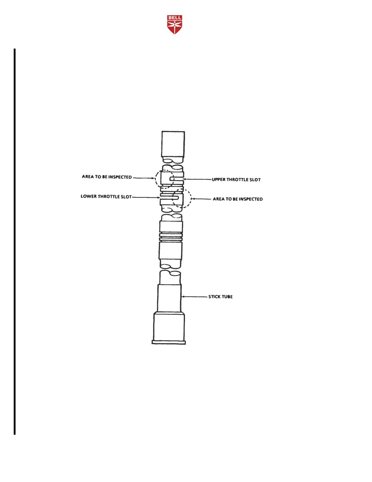
Referring to Figure 5-8, visually inspect stick tube for
cracks using a 3X magnifying glass and a bright light. Pay
particular attention to the base of the throttle slots that form the
twist grip stops.
3.
If a crack is found, replace stick tube.
4.
Reassemble pilot and copilot (if installed) collective
stick(s).
5.
Check throttle controls for proper operation.
6.
Check collective controls for proper operation.
5-00-00
Export Classification C, ECCN EAR99
15 MAY 2020 Rev. 18
Page 188A
BHT-212-MM-1
212_MM_05_0009
Figure 5-8. Collective Stick Tube
5-00-00
Page 188B
Rev. 18
15 MAY 2020
Export Classification C, ECCN EAR99
BHT-212-MM-1
CONDITIONAL INSPECTIONS
5-49.
CONDITION INSPECTION
3.
If applicable conditional inspection does not
provide complete information on a specific type of
1.
Perform applicable conditional inspection of
incident or if any doubt exists as to the serviceability of
helicopter after hard landing, after blade strike or other
the helicopter of related components, contact:
rotating system torque spike, overspeed, overtorque,
compressor stall or surge, lightning strikes, and after
reduction
(combining)
gearbox
clutch
Product Support Engineering
nonengagement, misengagement, or in-flight slippage
(paragraph 5-50 through paragraph 5-56).
12800 rue de l’Avenir
Mirabel, Quebec J7J 1R4
2.
If overhaul evaluation is specified, complete both
the conditional inspection and normal inspection
Fax:
(450) 433-0272
procedures (as applicable) for that component listed in
Tel:
(450) 437-6201or
BHT-212-CR&O manual.
800-363-8028 (U.S./Canada)
E-mail:
psemedium@bh.com
5-00-00
Export Classification C, ECCN EAR99
26 JUN 2013 Rev. 14
Page 189/190
BHT-212-MM-1
CONDITIONAL INSPECTIONS
5-50.
AFTER HARD LANDING
INITIAL
DATA REFERENCE
INSPECTION TASK DESCRIPTION
MECH OTHER
DATE:
__________________
W.O.
_____________________
FACILITY:
_________________________________________
HELICOPTER S/N:
__________________________________
REGISTRY NO.:
____________________________________
TOTAL TIME:_______________________________________
SIGNATURE:_______________________________________
NOTE
Accomplish inspection after hard landing.
AFTER HARD LANDING
NOTE
Evaluate components removed from a helicopter
following a hard landing as an interrelated group.
Make entries in component records of each removed
component to cross reference part and serial
numbers of other drive system components removed
for evaluation.
Hard landing is defined as any accident or incident in
which ground impact of helicopter results in yielding
or cracking of mounting lugs of transmission support
case or noticeable yielding or cracking of fuselage
pylon support structure, landing gear, or tailboom
attachment structure. This definition is confined only
to those accidents not involving sudden stoppage of
main rotor or tail rotor.
5-00-00
Export Classification C, ECCN EAR99
26 JUN 2013 Rev. 14
Page 191
BHT-212-MM-1
CONDITIONAL INSPECTIONS
5-50.
AFTER HARD LANDING (CONT)
INITIAL
DATA REFERENCE
INSPECTION TASK DESCRIPTION
MECH OTHER
- Inspect
1.
If a hard landing is suspected, step a through step h shall
be accomplished:
a. Inspect main and tail rotor blades for evidence of strike
damage. If such evidence is found on either rotor, perform
sudden stoppage - power on or off.
b. Visually inspect underside of fuselage and tailboom for
evidence of ground contact.
Chapter 32
c. Perform landing gear deflection check.
(1) If crosstubes have yielded, remove landing gear
and inspect support and attaching structure for signs of yielding
or other damage.
(2) If supports and attaching structure are not
damaged, replace damaged landing gear components.
d. Inspect mast for evidence of hard rotor hub contact
sufficient enough to yield or deform mast.
e. Inspect mast area around pylon mount for loose rivets
or other damage.
f. Inspect tailboom and fuselage attachment for loose
rivets, cracks, or other damage.
g. If no damage other than yielded landing gear
crosstubes has been found at this point, it is reasonably certain
a true hard landing did not occur. For helicopters on the Part A
inspection program, complete a 100 hour /12 month inspection.
For helicopters on the Part B inspection program, complete a 25
hour/15 day inspection and return helicopter to flight status
provided no further evidence of damage is found.
h. If damage is more extensive than landing gear
crosstube yielding, a hard landing has occurred. Comply with
requirements of step 2 through step 4.
5-00-00
Page 192
Rev. 14
26 JUN 2013
Export Classification C, ECCN EAR99
BHT-212-MM-1
CONDITIONAL INSPECTIONS
5-50.
AFTER HARD LANDING (CONT)
INITIAL
DATA REFERENCE
INSPECTION TASK DESCRIPTION
MECH OTHER
2.
If a hard landing has occurred, the following steps shall be
accomplished:
a. Remove and perform an overhaul evaluation inspection
of following components:
(1) Mast assembly
NOTE
If there is any yielding or deformation in area
contacted by main rotor hub static stops or any other
obvious damage, mast is unserviceable and
non-repairable.
(2) Transmission
(3) Main driveshaft
b. Perform a thorough visual inspection of following
components that may be kept in service if no discrepancy or
obvious damage is found. Replace any damaged component:
(1) Main rotor blades
(2) Main rotor hub
(3) Tail rotor blades
(4) Tail rotor hub
ASB 212-96-100 and
NOTE
ASB 212-96-101
Inspect trunnion assembly 212-010-738 or flapping
stop 212-011-713 for yielding as noted in Chapter 64
to determine if tail rotor yoke assembly may have
been exposed to bending.
(5) Tail rotor static stop
(6) Tail rotor yoke
(7) Intermediate gearbox
5-00-00
Export Classification C, ECCN EAR99
26 JUN 2013 Rev. 14
Page 193
BHT-212-MM-1
CONDITIONAL INSPECTIONS
5-50.
AFTER HARD LANDING (CONT)
INITIAL
DATA REFERENCE
INSPECTION TASK DESCRIPTION
MECH OTHER
(8) Tail rotor gearbox
(9) Tail rotor driveshafts
(10) Tail rotor driveshaft hangers
(11) Swashplate and support assembly
(12) Scissors and sleeve assembly and collective
levers
(13) Stabilizer bar assembly
(14) Helicopter structure directly supporting damaged
components identified in previous inspections
c. Check all cowling and doors for proper fit and
alignment. Remove cowling and inspect all attachment fittings.
NOTE
If significant damage has been found in any area of
airframe, inspection shall be expanded in those
areas until it extends beyond zone of damage.
d. Make a complete inspection, using a 10X magnifying
glass, of pylon support structure for loose or sheared rivets,
cracked brackets, buckled or cracked support angles and webs.
Pay particular attention to pylon mounts attaching points.
e. Make a complete inspection of lift link, lift link
attachment fittings, and lift beam for cracks and other evidence
of damage. Remove lift link and replace with like serviceable
item, if damaged.
f. Remove both pylon dampers, disassemble and check
for internal yielding. Assemble dampers and install if no
evidence of damage exists. Replace with like serviceable item if
any damage is found.
g. Install serviceable mast, transmission assembly, and
main driveshaft assembly. Install removed pylon control
components.
5-00-00
Page 194
Rev. 14
26 JUN 2013
Export Classification C, ECCN EAR99
BHT-212-MM-1
CONDITIONAL INSPECTIONS
5-50.
AFTER HARD LANDING (CONT)
INITIAL
DATA REFERENCE
INSPECTION TASK DESCRIPTION
MECH OTHER
h. Check all engine mount fittings and bolts for damage
and looseness.
i. Inspect engine firewalls for evidence of warping,
crushing, or other damage.
j. Make a complete inspection of area where tailboom is
attached to forward fuselage section. This includes both sets of
attachment fittings and longerons, beam caps, skins, webs,
bulkhead flanges, and other structural members. Check torque
on attachment bolts to determine if yielding has occurred.
k. Completely inspect flight control system from pilot (and
copilot) controls to rotor head for bent or damaged tubes,
bellcranks, bellcrank supports, and for damaged control system
bearings. Particular attention should be given to pylon controls,
lower cylinder attachment support fitting, and adjacent airframe
structure.
l. Pressurize hydraulic systems and check for leaks,
interference, binding, and satisfactory operation.
m. Inspect fuel, oil, and pneumatic system for damage.
Make engine ground run and visually check fuel, oil, and
pneumatic lines for leaks.
Pratt & Whitney
3.
Inspect power plant in accordance with Pratt & Whitney
Canada PT6T-3/-3B
Canada PT6T-3/-3B Maintenance Manual.
Maintenance Manual
4.
If no significant damage has been found, no further
inspection is necessary.
5-00-00
Export Classification C, ECCN EAR99
26 JUN 2013 Rev. 14
Page 195/196
BHT-212-MM-1
CONDITIONAL INSPECTIONS
5-51.
AFTER BLADE STRIKE OR OTHER ROTATING SYSTEM TORQUE SPIKE
INITIAL
DATA REFERENCE
INSPECTION TASK DESCRIPTION
MECH OTHER
DATE:
__________________
W.O.
_____________________
FACILITY:
_________________________________________
HELICOPTER S/N:
__________________________________
REGISTRY NO.:
____________________________________
TOTAL TIME:_______________________________________
SIGNATURE:_______________________________________
NOTE
To be accomplished after a main rotor blade or tail
rotor blade strike or any drive system failure that
inhibits free rotation of drive system.
AFTER BLADE STRIKE OR OTHER ROTATING SYSTEM
TORQUE SPIKE
NOTE
If the blade strike or rotating system torque spike is
the result of crash damage or results in crash
damage, all rotating system components shall be
considered unserviceable and non-repairable.
Crash damage is any damage sustained beyond the
scope of that identified in the After Hard Landing
conditional inspection (paragraph 5-50).
5-00-00
Export Classification C, ECCN EAR99
26 JUN 2013 Rev. 14
Page 197
BHT-212-MM-1
CONDITIONAL INSPECTIONS
5-51.
AFTER BLADE STRIKE OR OTHER ROTATING SYSTEM TORQUE SPIKE (CONT)
INITIAL
DATA REFERENCE
INSPECTION TASK DESCRIPTION
MECH OTHER
NOTE
Components removed from a helicopter for
evaluation following a sudden stoppage shall be
evaluated as an interrelated group. Removal records
accompanying
each
component
shall
cross-reference part and serial numbers of other
drive system components removed for evaluation.
Sudden stoppage is defined as any rapid
deceleration of drive system whether caused by
seizure within helicopter transmission or by contact
of main or tail rotor blades with the ground, water,
snow, dense vegetation, trees, or other objects of
sufficient density to cause rapid deceleration. Main or
tail rotor blade damage, when caused by striking
some object sufficient to require blade replacement
(defined as removal for repair or scrap), is
considered sudden stoppage. When sudden
stoppage occurs, inspect helicopter and replace
components as follows:
1.
Perform a sudden stoppage inspection as follows:
NOTE
If sudden stoppage inspection is the result of a tail
rotor strike or main rotor blades striking the tail rotor
driveshaft, comply with step g through step n.
a. Main rotor blades.
(1) Visually inspect both main rotor blades for
evidence of damage. Check closely for wrinkled skin.
(2) If any blade is damaged sufficiently to require
blade repair, return both blades to an authorized overhaul
facility. Make an entry in component record to show reason for
removal was sudden stoppage.
(3) If no evidence of damage is found on either blade,
both blades may be retained in service.
5-00-00
Page 198
Rev. 14
26 JUN 2013
Export Classification C, ECCN EAR99
BHT-212-MM-1
CONDITIONAL INSPECTIONS
5-51.
AFTER BLADE STRIKE OR OTHER ROTATING SYSTEM TORQUE SPIKE (CONT)
INITIAL
DATA REFERENCE
INSPECTION TASK DESCRIPTION
MECH OTHER
b. Main rotor hub.
(1) If main rotor blades were not damaged sufficiently
to require blade replacement, hub may be retained in service.
BHT-212-CR&O
(2) If a main rotor blade is damaged sufficiently to
require blade replacement, perform overhaul inspection on main
rotor hub. If any doubt exists, contact Product Support
Engineering.
(3) If a main rotor blade is damaged beyond repair,
scrap 204-011-121 grips and perform overhaul evaluation on
main rotor hub. Make entry in component record to show reason
for removal was sudden stoppage.
c. Pylon control components.
BHT-212-CR&O
(1) If one or more of the following discrepancies in
step (a) through step (f) are found, swashplate assembly,
stabilizer bar assembly, and scissors and sleeve assembly shall
be removed and an overhaul evaluation performed.
(a) Severe main rotor blade damage sufficient to
require replacement.
(b) Pitch horn failure.
(c) Yielded stabilizer bar tube.
(d) Control tube buckled or broken.
(e) Transmission main support case mounting leg
broken.
(f)
Damaged isolation mounts.
If no condition exists as listed in preceding step (1), perform a
close visual inspection. If no evidence of damage is found, the
swashplate assembly, stabilizer bar assembly, and scissors
and sleeve assembly may remain in service.
d. Replace all bolts in rotating controls. Discard removed
bolts.
5-00-00
Export Classification C, ECCN EAR99
26 JUN 2013 Rev. 14
Page 199
BHT-212-MM-1
CONDITIONAL INSPECTIONS
5-51.
AFTER BLADE STRIKE OR OTHER ROTATING SYSTEM TORQUE SPIKE (CONT)
INITIAL
DATA REFERENCE
INSPECTION TASK DESCRIPTION
MECH OTHER
BHT-212-CR&O
e. Remove and inspect main driveshaft visually. If
evidence of yielding or deformation is noted, scrap driveshaft
assembly and attaching bolts. If no visual evidence of damage
is detected, perform an overhaul evaluation. Make an entry in
component record to show reason for removal and sudden
stoppage.
f. Transmission and mast assembly.
(1) The following criteria are established to determine
the need for removal and overhaul of the transmission and mast
assembly. If any doubt exists contact Product Support
Engineering.
(a) Damage to the main rotor blades due to
striking a foreign object requiring removal to repair or scrap
blades.
(b) Damage to the main rotor hub due to the main
rotor blades striking a foreign object.
(c) Damage or shearing of main rotor mast.
(d) Seizure of drive system components.
NOTE
The transmission and mast assembly must be
evaluated for serviceability as a set when removed
for inspection requirements due to sudden stoppage.
Inspect in accordance with the BHT-212-CR&O
manual, ensuring both conditional and normal
inspections are accomplished.
BHT-212-CR&O
NOTE
If mast has evidence of torsional yielding (defined as
excessive runout, bending, deformation or spline
misalignment), mast assembly (including mast
bearing), transmission top case, transmission lower
planetary spider, lower mast bearing, and pylon
mounts shall be scrapped. The transmission shall be
overhaul evaluated. If the main case is magnesium it
shall be scrapped.
5-00-00
Page 200
Rev. 14
26 JUN 2013
Export Classification C, ECCN EAR99
BHT-212-MM-1
CONDITIONAL INSPECTIONS
5-51.
AFTER BLADE STRIKE OR OTHER ROTATING SYSTEM TORQUE SPIKE (CONT)
INITIAL
DATA REFERENCE
INSPECTION TASK DESCRIPTION
MECH OTHER
If mast assembly does not exhibit evidence of
torsional yielding and transmission has no obvious
damage that would render it non-repairable, perform
an overhaul evaluation on both the transmission and
mast assembly.
If transmission is considered non-repairable as a
result of sudden stoppage, the mast assembly shall
be scrapped.
If a main rotor blade is damaged beyond repair, main
rotor mast assembly (204-011-450-ALL) shall be
scrapped.
In all cases, make an entry in component records to
show reason for component removal was sudden
stoppage.
g. Tail rotor driveshaft hanger assemblies:
(1) If a tail rotor driveshaft has been damaged beyond
limits due to contact with a main rotor blade or other similar
circumstance, the hanger assemblies to which the damaged
shaft was attached shall be scrapped. If a tail rotor driveshaft
fails as a result of torsional overload, all hanger assemblies and
shafts shall be scrapped.
BHT-212-CR&O
(2) If inspection reveals no damage that would render
hanger assemblies non-repairable, hanger assemblies shall
have an overhaul evaluation performed. Make an entry in
component record to show reason for removal is blade strike or
torque spike.
Chapter 65
h. Tail rotor driveshaft.
(1) Remove tail rotor driveshafts and inspect for
following conditions. If one or more of conditions listed in
step (a) through step (e) are noted, all driveshafts and bearing
hangers shall be considered unserviceable and non-repairable
and shall be scrapped.
(a) Curvic faces distorted.
(b) Evidence of overload.
5-00-00
Export Classification C, ECCN EAR99
26 JUN 2013 Rev. 14
Page 201
BHT-212-MM-1
CONDITIONAL INSPECTIONS
5-51.
AFTER BLADE STRIKE OR OTHER ROTATING SYSTEM TORQUE SPIKE (CONT)
INITIAL
DATA REFERENCE
INSPECTION TASK DESCRIPTION
MECH OTHER
(c) Cracks.
(d) Loose or sheared rivets.
(e) Scratches in excess of limits.
(2) If inspection reveals no condition as previously
listed in step (a) through step (e) exists, driveshaft may remain
in service.
i. Tail rotor hub and blade assembly.
NOTE
Nicks, scratches, or dents on top or bottom of blade
(nonleading edge) that do not require removal of
blades for replacement may not require the tail rotor
assembly to be scrapped. If any doubt exists, contact
Product Support Engineering.
(1) Tail rotor hub and blade assembly: If sudden
stoppage originated at tail rotor blades, tail rotor hub assembly
shall be considered unserviceable and non-repairable and must
be discarded.
(a) If sudden stoppage originated at main rotor or
main rotor transmission, tail rotor hub and blade assembly may
remain in service provided there is no visible external damage.
If visible damage is noted on tail rotor hub and blade assembly,
an overhaul of the tail rotor hub shall be performed. Make an
entry in component records to show reason for removal was
sudden stoppage.
(b) If sudden stoppage originated at tail rotor
driveshaft, intermediate gearbox, or tail rotor gearbox remove
tail rotor hub and blade assembly and perform an overhaul of
the tail rotor hub. Make an entry in component record to show
reason for removal was sudden stoppage.
(c) If either tail rotor blade is damaged sufficiently
to require blade repair, return both blades to an authorized
overhaul facility. Make an entry in component record to show
that reason for removal was sudden stoppage.
5-00-00
Page 202
Rev. 14
26 JUN 2013
Export Classification C, ECCN EAR99
BHT-212-MM-1
CONDITIONAL INSPECTIONS
5-51.
AFTER BLADE STRIKE OR OTHER ROTATING SYSTEM TORQUE SPIKE (CONT)
INITIAL
DATA REFERENCE
INSPECTION TASK DESCRIPTION
MECH OTHER
(d) If no evidence of damage is found on either
tail rotor blade, both blades may remain in service.
(2) Tail rotor hubs with 212-011-702 yoke assembly
and 212-011-713-103 flapping stop, reference ASB 212-96-101.
Tail rotor hubs with
212-010-704-ALL yoke assembly or
212-010-744-ALL yoke assembly and
212-010-738-001
trunnion assembly, reference ASB 212-96-100.
(a) Inspect
212-011-713 and
212-010-738
flapping stops for yielding, to determine if tail rotor yoke
assembly may have been exposed to bending. A yielded
flapping stop requires removal of the tail rotor yoke and flapping
stop, and they shall be considered unserviceable and
non-repairable, and must be discarded.
j. Tail rotor rotating controls.
(1) Perform a close visual inspection of the tail rotor
rotating controls. If no evidence of damage is found, the tail
rotor rotating control may remain in service. Replace all tail rotor
rotating control bolts. If damage to the tail rotor rotating controls
is found, perform an overhaul of the tail rotor rotating controls.
Make an entry in component record to show that reason for
removal was sudden stoppage.
k. Tail rotor gearbox.
(1) Remove tail rotor gearbox. Check for cracks,
sheared or bent attaching studs, and evidence of case
distortion. If any of these conditions are noted, gearbox is
unserviceable and non-repairable and shall be scrapped.
BHT-212-CR&O
(2) If inspection reveals no condition as listed in
previous step (1), perform an overhaul evaluation. Make an
entry in component record to show reason for removal was
sudden stoppage.
l. Intermediate gearbox.
(1) Remove intermediate gearbox. Check for cracks,
case distortion, or broken lugs. If any of these conditions are
noted, gearbox is unserviceable and non-repairable and shall
be scrapped.
5-00-00
Export Classification C, ECCN EAR99
26 JUN 2013 Rev. 14
Page 203
BHT-212-MM-1
CONDITIONAL INSPECTIONS
5-51.
AFTER BLADE STRIKE OR OTHER ROTATING SYSTEM TORQUE SPIKE (CONT)
INITIAL
DATA REFERENCE
INSPECTION TASK DESCRIPTION
MECH OTHER
BHT-212-CR&O
(2) If inspection reveals no condition as listed in
previous step (1), perform an overhaul. Make an entry in
component record to show reason for removal was sudden
stoppage.
m. Transmission sump case.
NOTE
If no evidence of damage was found in step g
through step k, or step l, omit following step (1)
through step (3).
(1) If damage was found on bearing hangers, tail rotor
driveshaft, intermediate gearbox, or tail rotor gearbox, remove
tail rotor drive output quill from transmission sump case
assembly.
(2) Inspect output quill pinion for unusual load patterns
on both sides of teeth. If no damage is found, reinstall quill.
Transmission may be retained in service.
BHT-212-CR&O
(3) If tail rotor quill reveals discrepancies, remove
transmission and perform an overhaul evaluation. Make an
entry in component record to show reason for removal was
sudden stoppage.
n. Reinstall or replace, as applicable, all removed
components with serviceable components.
Pratt & Whitney
o. Inspect engine in accordance with Pratt & Whitney
Canada PT6T-3/-3B
Canada PT6T-3/-3B Maintenance Manual.
Maintenance Manual
5-00-00
Page 204
Rev. 14
26 JUN 2013
Export Classification C, ECCN EAR99
BHT-212-MM-1
CONDITIONAL INSPECTIONS
5-52.
AFTER OVERSPEED
INITIAL
DATA REFERENCE
INSPECTION TASK DESCRIPTION
MECH OTHER
DATE:
__________________
W.O.
_____________________
FACILITY:
_________________________________________
HELICOPTER S/N:
__________________________________
REGISTRY NO.:
____________________________________
TOTAL TIME:_______________________________________
SIGNATURE:_______________________________________
NOTE
Accomplish inspection after overspeed.
AFTER OVERSPEED
NOTE
Components removed from a helicopter for
evaluation following an overspeed shall be evaluated
as an interrelated group. Removal records
accompanying
each
component
shall
cross-reference part and serial numbers of other
drive system components removed for evaluation.
Overspeed is defined as any incident in which 110%
main rotor RPM is exceeded.
1.
Perform overspeed inspection as follows:
Pratt & Whitney
a. Refer to Pratt & Whitney Canada PT6T-3/-3B
Canada PT6T-3/-3B
Maintenance Manual for engine overspeed and inspection
Maintenance Manual
requirements.
b. Main rotor hub assembly.
(1) Remove main rotor hub. Remove main rotor
blades.
5-00-00
Export Classification C, ECCN EAR99
26 JUN 2013 Rev. 14
Page 205
BHT-212-MM-1
CONDITIONAL INSPECTIONS
5-52.
AFTER OVERSPEED (CONT)
INITIAL
DATA REFERENCE
INSPECTION TASK DESCRIPTION
MECH OTHER
BHT-212-CR&O
(2) Perform an overhaul conditional evaluation
inspection. Make an entry in component record to show reason
for removal was overspeed. Include amount of overspeed and
duration, if known.
BHT-212-CR&O
(3) Inspect main rotor blade retention bolts and drag
brace bolts.
c. Main rotor blades.
(1) Inspect main rotor blades skin for wrinkles and
deformation.
(2) If no discrepancies are found in inspections
outlined in step (1), main rotor blades may be retained in
service.
(3) If discrepancies are found in step (1), return both
blades to an authorized blade repair station. Make an entry in
component record to show reason for removal was overspeed.
Include amount of overspeed and duration, if known.
d. Tail rotor hub and blades.
(1) Remove tail rotor hub and blade assembly.
(2) Remove tail rotor blades.
(3) Replace tail rotor blade retention bolts.
e. Tail rotor blades.
BHT-212-CR&O
(1) Perform major overspeed inspection of tail rotor
blades. Make an entry in component record to show reason for
removal was overspeed.
f. Perform a close inspection of the following components.
If no visual damage is found, components may be retained in
service.
(1) Main transmission.
(2) Intermediate gearbox. Check gearbox for security
and retaining bolts.
5-00-00
Page 206
Rev. 14
26 JUN 2013
Export Classification C, ECCN EAR99
BHT-212-MM-1
CONDITIONAL INSPECTIONS
5-52.
AFTER OVERSPEED (CONT)
INITIAL
DATA REFERENCE
INSPECTION TASK DESCRIPTION
MECH OTHER
(3) Tail rotor gearbox. Check gearbox for security and
retorque retaining nuts.
(4) Main rotor mast.
(5) Main input driveshaft.
(6) Tail rotor driveshafts.
(7) Tail rotor driveshaft hangers.
(8) Stabilizer bar.
(9) Swashplate.
(10) Scissors and sleeve.
(11) Tail rotor hub.
g. Install a serviceable main rotor hub and blade
assembly. Install serviceable tail rotor blades. Balance and
install tail rotor hub and blade assembly.
5-00-00
Export Classification C, ECCN EAR99
26 JUN 2013 Rev. 14
Page 207/208
BHT-212-MM-1
CONDITIONAL INSPECTIONS
5-53.
AFTER OVERTORQUE
INITIAL
DATA REFERENCE
INSPECTION TASK DESCRIPTION
MECH OTHER
DATE:
__________________
W.O.
_____________________
FACILITY:
_________________________________________
HELICOPTER S/N:
__________________________________
REGISTRY NO.:
____________________________________
TOTAL TIME:_______________________________________
SIGNATURE:_______________________________________
NOTE
Accomplish inspection after overtorque.
AFTER OVERTORQUE
NOTE
Components removed from a helicopter for
evaluation following an overtorque shall be evaluated
as an interrelated group. Removal records
accompanying
each
component
shall
cross-reference part and serial numbers of other
drive system components removed for evaluation.
Overtorque is defined as any incident in which
torsional loads are introduced into the helicopter
dynamic system in excess of established limits.
Pratt & Whitney
1.
Refer to Pratt & Whitney Canada PT6T-3/-3B Maintenance
Canada PT6T-3/-3B
Manual for engine overtorque inspection limits.
Maintenance Manual
NOTE
To assist with determining engine overtorque
inspection requirements, the following table provides
a comparison between Bell Helicopter cockpit torque
gauge
% values and Pratt & Whitney Canada
Maintenance Manual FT LB values.
5-00-00
Export Classification C, ECCN EAR99
26 JUN 2013 Rev. 14
Page 209
BHT-212-MM-1
CONDITIONAL INSPECTIONS
5-53.
AFTER OVERTORQUE (CONT)
INITIAL
DATA REFERENCE
INSPECTION TASK DESCRIPTION
MECH OTHER
PT6T-3
PT6T-3B
BELL %
P&WC
BELL %
P&WC
TORQUE
FT LB
TORQUE
FT LB
87.6
900
89.1
915
83.6
859
85.2
875
77.8
800
79.4
815
71.8
738
71.8
738
2.
When overtorque has not exceeded 104% (108% for
helicopters with TB 212-91-138 incorporated), perform thorough
visual inspection of the following components. If inspection does
not reveal any discrepancies or obvious damage to
components, the components may be retained in service.
a. Tail rotor blades.
b. Main rotor hub.
c. Tail rotor hub.
d. Intermediate gearbox. Check gearbox for security and
retorque retaining bolts.
e. Tail rotor gearbox. Check gearbox for security and
retorque retaining nuts.
f. Tail rotor driveshafts.
g. Tail rotor driveshaft hangers.
h. Stabilizer bar assembly.
i. Swashplate.
j. Scissors and sleeve assembly.
k. Main driveshaft.
5-00-00
Page 210
Rev. 14
26 JUN 2013
Export Classification C, ECCN EAR99
BHT-212-MM-1
CONDITIONAL INSPECTIONS
5-53.
AFTER OVERTORQUE (CONT)
INITIAL
DATA REFERENCE
INSPECTION TASK DESCRIPTION
MECH OTHER
l. Mast.
m. Transmission.
3.
When overtorque exceeds 104% (108% for helicopters
with TB 212-91-138 incorporated), but does not exceed 112%
perform the following:
a. Perform thorough visual inspection of components
listed in step 2.
b. Inspect main transmission chip detector(s).
c. Inspect main transmission internal filter or full flow
debris monitor (as applicable).
(1) If metal particles are found, indicating internal
failure, remove transmission for overhaul evaluation. Make an
entry in the component record explaining reason for removal
was overtorque. Remove all transmission system oil lines. Flush
and reinstall oil lines. Replace external oil filter element.
Remove and scrap oil cooler. Install new oil cooler.
(2) If chip detector(s) and internal filter or full flow
debris monitor (as applicable) appear normal and there is no
evidence of internal failure, return helicopter to service. Operate
normally for 5 hours and then check chip detector(s) and
internal filter or full flow debris monitor. If no metal particles are
found indicating internal failure, normal scheduled inspection
intervals may then be followed. If metal particles are present
prior to or at the 5 hour check, or if there is any evidence of
internal failure, remove transmission for overhaul evaluation.
Make an entry in the component record explaining reason for
removal was overtorque. Remove all transmission system oil
lines. Flush and reinstall oil lines. Replace external oil filter
element. Remove and scrap oil cooler. Install new oil cooler.
d. Remove fifth mount bolts and remove fifth mount.
Perform a thorough inspection of bolts and fifth mount support.
Check for bent bolts and bent fifth mount support. Check for bolt
hole alignment between transmission and fifth mount support.
5-00-00
Export Classification C, ECCN EAR99
26 JUN 2013 Rev. 14
Page 211
BHT-212-MM-1
CONDITIONAL INSPECTIONS
5-53.
AFTER OVERTORQUE (CONT)
INITIAL
DATA REFERENCE
INSPECTION TASK DESCRIPTION
MECH OTHER
4.
When overtorque has exceeded
112% perform the
following:
a. Return the following components to an overhaul facility
for overhaul evaluation.
NOTE
Component removal record of dynamic components
shall reflect overtorque as reason for removal.
Include amount of overtorque and duration, if known.
(1) Transmission.
(2) Main driveshaft.
(3) Main rotor hub.
(4) Mast.
(5) Perform thorough visual inspection of other
components outlined in step 2.
b. Remove fifth mount bolts and remove fifth mount.
Perform a thorough inspection of bolts and fifth mount support.
Check for bent bolts and bent fifth mount support. Check for bolt
hole alignment between transmission and fifth mount support.
5-00-00
Page 212
Rev. 14
26 JUN 2013
Export Classification C, ECCN EAR99
BHT-212-MM-1
CONDITIONAL INSPECTIONS
5-54.
AFTER ENGINE COMPRESSOR STALL OR SURGE
INITIAL
DATA REFERENCE
INSPECTION TASK DESCRIPTION
MECH OTHER
DATE:
__________________
W.O.
_____________________
FACILITY:
_________________________________________
HELICOPTER S/N:
__________________________________
REGISTRY NO.:
____________________________________
TOTAL TIME:_______________________________________
SIGNATURE:_______________________________________
NOTE
Accomplish inspection after engine compressor stall
or surge.
AFTER ENGINE COMPRESSOR STALL OR SURGE
NOTE
Discuss circumstances of reported compressor stall
with pilot, if possible. Determine N1 (GAS PROD)
speed at which reported stall occurred. Check
helicopter and engine logs for any pertinent history.
Engine compressor stall or surge is characterized by
a sharp rumble or a series of loud sharp reports,
severe engine vibration and a rapid rise in
Interturbine Temperature (ITT), depending on
severity of surge. When a surge has been reported,
progressively perform the following inspections as
dictated by discrepant conditions.
Components removed from a helicopter for
evaluation following a compressor stall or surge shall
be evaluated as an interrelated group. Removal
records accompanying each component shall
cross-reference part and serial numbers of other
drive system components removed for evaluation.
5-00-00
Export Classification C, ECCN EAR99
26 JUN 2013 Rev. 14
Page 213
BHT-212-MM-1
CONDITIONAL INSPECTIONS
5-54.
AFTER ENGINE COMPRESSOR STALL OR SURGE (CONT)
INITIAL
DATA REFERENCE
INSPECTION TASK DESCRIPTION
MECH OTHER
1.
Power plant.
a. Examine inlet screen for blockage.
Pratt & Whitney
b. Inspect engine compressor region for salt, dust, oil, or
Canada PT6T-3/-3B
other contaminants. If contaminants are found, clean and
Maintenance Manual
perform a power check in accordance with Pratt & Whitney
Canada PT6T-3/-3B Maintenance Manual.
c. Inspect for visible Foreign Object Damage (FOD) to
visible compressor blades.
Pratt & Whitney
d. If compressor stall (surge) occurred during acceleration,
Canada PT6T-3/-3B
refer to Pratt & Whitney Canada PT6T-3/-3B Maintenance
Maintenance Manual
Manual for inspection procedures.
Pratt & Whitney
e. Perform test on pneumatic sense lines.
Canada PT6T-3/-3B
Maintenance Manual
Pratt & Whitney
f. If step a through step e do not reveal cause of surge,
Canada PT6T-3/-3B
perform a hot end inspection in accordance with Pratt &
Maintenance Manual
Whitney Canada PT6T-3/-3B Maintenance Manual.
2.
Power train.
a. If compressor stall occurs below 85% N1 (GAS PROD)
speed, comply with step b and step c.
b. Remove magnetic chip detectors from transmission,
intermediate gearbox, and tail rotor gearbox. Inspect for metal
particles.
c. If no evidence of damage is found on tailboom pylon
and no indication of metal particles are found on chip detectors,
clean chip detectors and reinstall. Return helicopter to flight
status and repeat chip detector inspection after
5 to
10
operating hours. If positive indication of damage is found on
tailboom pylon or metal chips are found on chip detectors,
during initial or 5 to 10 hour inspection, comply with the
following step e through step i.
d. If compressor stall occurs at 85% N1 (GAS PROD) or
above, comply with the following step e through step i.
5-00-00
Page 214
Rev. 14
26 JUN 2013
Export Classification C, ECCN EAR99
BHT-212-MM-1
CONDITIONAL INSPECTIONS
5-54.
AFTER ENGINE COMPRESSOR STALL OR SURGE (CONT)
INITIAL
DATA REFERENCE
INSPECTION TASK DESCRIPTION
MECH OTHER
Chapter 65
e. Remove and inspect tail rotor driveshaft.
f. Remove input and output drive quill from intermediate
gearbox and inspect gear teeth on pinion and gear for damage
with a 10X magnifying glass. if no evidence of scoring or
scuffing is found, and there is no mechanical damage that would
render gearbox unserviceable, reassemble and return to
service. If gear teeth are scuffed or scored, or gearbox has
sustained other damage, gearbox shall be replaced with a like,
serviceable item and the following step g and step h
accomplished.
g. Remove tail rotor gearbox from helicopter and remove
input quill. Inspect gear teeth on pinion and gear for damage
with a 10X magnifying glass. If no evidence of scoring or
scuffing is found, and there is no other damage that would
render gearbox unserviceable, it may be reassembled and
reinstalled for continued use. If gear teeth are scored or scuffed,
or there is other damage that would render gearbox
unserviceable, replace gearbox with a like, serviceable item.
h. Remove tail rotor drive quill from transmission and
inspect gear teeth for damage with a 10X magnifying glass. If
there is no indication of scoring or scuffing, and there is no other
damage that would render transmission unserviceable, it is
suitable for continued use. If gear teeth are scored or scuffed, or
there is other damage and that would render transmission
unserviceable, replace transmission with a like, serviceable item
and comply with step j.
i. Install serviceable tail rotor driveshaft if transmission is
not to be replaced.
j. If transmission is to be replaced, the following
components shall also be replaced (step (1) through step (3)
and procedures outlines in step (4) through step (8) performed).
(1) Tail rotor bearing hanger assemblies.
(2) Tail rotor driveshafts.
BHT-212-CR&O
(3) Tail rotor hub and blade assembly. Perform an
overhaul. Make an entry in component record to show reason
for removal was compressor stall.
5-00-00
Export Classification C, ECCN EAR99
15 MAY 2020 Rev. 18
Page 215