Helicopter Bell-212. MAINTENANCE MANUAL (2021) - page 2
BHT-212-MM-1
SCHEDULED INSPECTIONS
5-8.
DAILY INSPECTION - PART A (CONT)
DATA
INITIAL
INSPECTION TASK DESCRIPTION
REFERENCE
MECH OTHER
4.
Proper oil level.
Chapter 71
RIGHT POWER SECTION
- Detailed Visual Inspection
1.
Gas generator case for cracks buckled areas, and hot spots.
2.
Oil and fuel hoses and tubes for chafing, leaking, and
security.
3.
Electrical wiring for fraying, chafing, and security.
4.
Proper oil level.
Chapter 71
REDUCTION GEARBOX
- Detailed Visual Inspection
1.
Hoses and lines for security, leaks, and chafing.
2.
Oil filter impending bypass indicator button not extended.
3.
Proper oil level.
Chapter 71
ENGINE AND REDUCTION GEARBOX MOUNTS
- Detailed Visual Inspection
1.
Mounts for loose bearings and security.
ENGINE FIREWALLS
- Detailed Visual Inspection
1.
Firewalls for cracks, distortion, missing rivets, broken spot
welds, and deteriorating seals or gaskets.
5-00-00
Page 26
Rev. 14
26 JUN 2013
Export Classification C, ECCN EAR99
BHT-212-MM-1
SCHEDULED INSPECTIONS
5-8.
DAILY INSPECTION - PART A (CONT)
DATA
INITIAL
INSPECTION TASK DESCRIPTION
REFERENCE
MECH OTHER
ENGINE AIR MANAGEMENT SYSTEM
- Detailed Visual Inspection
1.
Exhaust ejector and ducts for condition, obstruction, and
security.
2.
Air intake ducts and plenum for condition, obstruction, and
security.
Chapter 79
ENGINE OIL SYSTEM
- Detailed Visual Inspection
1.
Engine accessory and reduction gearboxes for oil leaks.
2.
Oil coolers for leaks, damage, or obstructions.
Chapter 95
INSTRUMENTS
- Detailed Visual Inspection
1.
Instrument panel for cleanliness.
2.
All instruments, placards, decals, and markings for
appearance and legibility.
3.
Check magnetic compass for condition and security.
4.
All compass cards for validity.
Chapter 96
ELECTRICAL SYSTEMS
- General Visual Inspection
1.
Nose compartment electrical equipment for condition and
security.
2.
Pedestal mounted avionics/electrical equipment for
condition, cleanliness, and security.
3.
Overhead console for condition, cleanliness, and security.
5-00-00
Export Classification C, ECCN EAR99
15 MAY 2020 Rev. 18
Page 27
BHT-212-MM-1
SCHEDULED INSPECTIONS
5-8.
DAILY INSPECTION - PART A (CONT)
DATA
INITIAL
INSPECTION TASK DESCRIPTION
REFERENCE
MECH OTHER
4.
All instrument lights, integrally lit panels, secondary lights,
and map lights for serviceability.
5.
All caution and warning lights for proper operation by using
master caution, fire test, and baggage compartment smoke
detector press to test functions.
6.
Landing/search lights for condition and security.
7.
Navigation and anticollision lights for condition and security.
Chapter 96
BATTERY SYSTEM
- General Visual Inspection
1.
Battery and external connections for condition and security.
2.
Battery vent and drain tubes for obstruction and security.
Chapter 97
ANTENNAS
1.
Visually inspect all antennas located on fuselage and
tailboom for condition and security.
Chapter 97
AVIONICS EQUIPMENT
1.
Visually inspect all avionics located in fuselage and tailboom
for condition and security.
5-00-00
Page 28
Rev. 18
15 MAY 2020
Export Classification C, ECCN EAR99
BHT-212-MM-1
SCHEDULED INSPECTIONS
5-9.
100 HOURS/12 CALENDAR MONTHS - PART A
INITIAL
DATA REFERENCE
INSPECTION TASK DESCRIPTION
MECH OTHER
DATE:
__________________
W.O.
_____________________
FACILITY:
_________________________________________
HELICOPTER S/N:
__________________________________
REGISTRY NO.:
____________________________________
TOTAL TIME:_______________________________________
SIGNATURE:_______________________________________
NOTE
For helicopters on the Part A inspection program,
accomplish each 100 hours of flight operation or after
12 calendar months, whichever comes first.
GENERAL
1.
Each listed inspection item or maintenance function is to
be performed in accordance with the referenced maintenance
manual, chapter specified, or BHT-212-CR&O manual.
2.
Refer to Pratt & Whitney Canada PT6T-3/-3B Maintenance
Manual for engine inspection requirements.
3.
Record all work accomplished during inspection in the
helicopter maintenance record.
4.
Check helicopter records for recorded discrepancies.
5.
Accomplish complete Daily Inspection - Part A scheduled
inspection program.
Paragraph 5-16
6.
Review special inspections and perform any special
inspection required.
Chapter 4
7.
Replace all finite life components that have completed
published operating limitations.
Paragraph 5-57
8.
Overhaul all components which have completed published
overhaul periods.
5-00-00
Export Classification C, ECCN EAR99
15 MAY 2020 Rev. 18
Page 29
BHT-212-MM-1
SCHEDULED INSPECTIONS
5-9.
100 HOURS/12 CALENDAR MONTHS - PART A (CONT)
INITIAL
DATA REFERENCE
INSPECTION TASK DESCRIPTION
MECH OTHER
Chapter 12
9.
Perform lubrication requirements.
NOTE
The following step is to be performed every
12 calendar months.
10. Inspect all fuel system, oil system, and hydraulic system
filler caps for proper functioning and sealing. Make sure the
sealing O-rings within the filler caps are in good condition.
Repair or replace the filler caps or replace sealing O-rings as
required.
POWER CHECK
Chapter 96
1.
Examine all electrical components, wires, cables and
connectors in the area of the forward deck and transmission for
chafing, general condition and security.
GROUND RUN
CAUTION
GROUND RUN OF HELICOPTER TO BE
ACCOMPLISHED BY QUALIFIED PERSONNEL
ONLY.
Chapter 12
1.
Make sure applicable servicing requirements have been
carried out.
2.
Check oil level of transmission, hydraulic tank, engine and
tail rotor gearbox prior to running helicopter.
3.
Make sure that helicopter is ready for ground run and that
surrounding area is clear.
BHT-212-FM-1
4.
Start the helicopter and conduct ground run at 100% NR to
check for leaks and ensure all systems are operational and
parameters are within Flight manual limitations.
5.
Shut down the helicopter.
5-00-00
Page 30
Rev. 18
15 MAY 2020
Export Classification C, ECCN EAR99
BHT-212-MM-1
SCHEDULED INSPECTIONS
5-9.
100 HOURS/12 CALENDAR MONTHS - PART A (CONT)
INITIAL
DATA REFERENCE
INSPECTION TASK DESCRIPTION
MECH OTHER
Chapter 21
HEAT/VENT AIR DUCTS
1.
Visually inspect all heating, ventilation, cooling ducts, and
controls for cracks, security and proper operation.
Every sixth 100 hour inspection (600 hours) or 12 months:
Chapter 96
2.
Bleed air heating and ventilation/defog system
components:
a. Perform functional check of bleed air heating system
and components.
b. Perform functional check of defog blower.
Chapter 25
MISCELLANEOUS FURNISHINGS
1.
Check all safety equipment for inspection due dates and
operation.
Chapter 26
FIRE PROTECTION
1.
Make sure fire extinguishers are properly charged.
2.
Baggage compartment smoke detector for condition and
security.
Every sixth 100 hour inspection (600 hours) or 12 months:
1.
Weight check crew and passenger cabin portable fire
extinguishers.
Chapter 96
2.
Perform operational check of engine fire extinguishing
system.
3.
Perform operational check of baggage compartment
smoke detector.
Chapter 4
4.
Replace engine fire extinguisher container firing cartridges
in accordance with specified service life.
5-00-00
Export Classification C, ECCN EAR99
15 MAY 2020 Rev. 18
Page 31
BHT-212-MM-1
SCHEDULED INSPECTIONS
5-9.
100 HOURS/12 CALENDAR MONTHS - PART A (CONT)
INITIAL
DATA REFERENCE
INSPECTION TASK DESCRIPTION
MECH OTHER
Chapter 28
FUEL SYSTEM
1.
Inspect all exposed fuel lines and connections for leakage,
damage, and security.
Every sixth 100 hour inspection (600 hours) or 12 months:
2.
Remove four access doors, located just forward of the aft
crosstube, from the underside of the fuselage. Inspect fuel lines
for evidence of leakage, damage, and security.
Chapter 29
HYDRAULIC SYSTEMS
1.
Inspect all lines and hoses for security and general
condition.
Every sixth 100 hour (600 hours) inspection or 12 months:
NOTE
Hydraulic filter elements
205-076-034-003 are
non-cleanable. It is recommended they be replaced
every 600 hours or
12 months. Filter elements
205-076-034-007 are cleanable. The -003 and -007
elements are interchangeable; intermixing of
different element types is not permitted.
1.
Remove and inspect hydraulic filter elements.
2.
Discard or clean filter elements as applicable.
3.
Install hydraulic filter elements.
Chapter 63
4.
Install 0 to 500 PSIG (0 to 3447 kPa) gauge in quick
disconnect at rotor brake caliper. Slowly pull rotor brake handle
through travel. Cylinder should generate 240 to 260 PSI (1655
to 1793 kPA) at any handle velocity and shall maintain 150 PSI
(1034 kPa) minimum in over center position for 3 minutes.
Adjust as necessary.
5.
Inspect rotor brake linings for wear (minimum thickness
0.150 inch (3.81 mm)).
5-00-00
Page 32
Rev. 18
15 MAY 2020
Export Classification C, ECCN EAR99
BHT-212-MM-1
SCHEDULED INSPECTIONS
5-9.
100 HOURS/12 CALENDAR MONTHS - PART A (CONT)
INITIAL
DATA REFERENCE
INSPECTION TASK DESCRIPTION
MECH OTHER
Chapter 32
LANDING GEAR SYSTEM
- General Visual Inspection
1.
Deleted.
2.
Deleted.
3.
Landing gear crosstube assemblies, skid tubes, and skid
shoes, for condition and security of attachment. Inspect
crosstube retention cap (rubber bumper pads) for condition and
security of attachment.
4.
Deleted.
5.
Deleted.
6.
If installed, landing gear forward crosstube crew step
fittings for corrosion, damage, and security in area of
attachment. If edge sealant is damaged or missing, remove
crew step and inspect crosstube for corrosion or damage.
- Restoration
1.
Torque check crosstube to skid tube saddle bolts.
2.
Torque check forward and aft crosstube support fittings U
bolts to 80 to 100 inch-pounds (9.0 to 11.3 Nm).
3.
Torque check ground handling wheel attachment eyebolts
on skid tubes 40 to 58 foot-pounds (54 to 79 Nm). Eyebolts that
rotate prior to reaching 40 foot-pounds (54 Nm) shall be
removed and inspected for evidence of bending. No bending is
permitted.
Chapter 52
DOORS AND WINDOWS
1.
Crew and passenger doors structure for corrosion,
damage, distortion, and positive locking mechanisms. Seals for
adherence, tears, separations, and deterioration.
5-00-00
Export Classification C, ECCN EAR99
15 MAY 2020 Rev. 18
Page 33
BHT-212-MM-1
SCHEDULED INSPECTIONS
5-9.
100 HOURS/12 CALENDAR MONTHS - PART A (CONT)
INITIAL
DATA REFERENCE
INSPECTION TASK DESCRIPTION
MECH OTHER
Every third 100 hour inspection (300 hours) or 12 months:
2.
Crew doors emergency jettison mechanism for condition
and security. Perform operational check.
NOTE
The following inspection (step 3 and step 4) is for
helicopters equipped with escape panels which may
be identified by a rotating handle installed below the
passenger door windows. The handle is labeled
EMERGENCY RELEASE PULL COVER TURN
LEFT AND PUSH.
3.
Inspect passenger door emergency egress panel pins and
mechanisms for wear, corrosion, operation, and security.
4.
Perform operational check of passenger door escape
panels.
5.
Passenger door window retainers and fillers (if applicable)
for damage.
6.
Nose, electrical, and equipment compartment access
doors for corrosion, damage, distortion, and positive locking
mechanisms.
7.
Baggage compartment door for corrosion, damage, and
positive locking.
8.
Inspect heated windshield, if installed, for condition and
proper operation.
Chapter 53
TAILBOOM
- General Visual Inspection
ASB 212-90-63 and
1.
Internal and external structure of tailboom for cracks,
TB 212-94-147
distortion, corrosion, and security.
2.
Inspect tailboom attachment points for cracks and security.
3.
Ensure all drain holes are open.
5-00-00
Page 34
Rev. 18
15 MAY 2020
Export Classification C, ECCN EAR99
BHT-212-MM-1
SCHEDULED INSPECTIONS
5-9.
100 HOURS/12 CALENDAR MONTHS - PART A (CONT)
INITIAL
DATA REFERENCE
INSPECTION TASK DESCRIPTION
MECH OTHER
Chapter 65
4.
Torque check tail rotor gearbox mounting nuts by applying
torque in tightening direction, do not exceed 200 inch-pounds
(22.6 Nm). If any nut rotates under torque, inspect attachment
hardware and tail rotor gearbox for serviceability.
5.
Torque check intermediate gearbox mounting bolts by
applying torque in tightening direction, do not exceed
50
inch-pounds (5.65 Nm). If any bolt turns under torque, inspect
attachment hardware and intermediate gearbox for
serviceability.
ASB 212-00-110
6.
Inspect vertical fin spar caps for cracks and corrosion.
NOTE
If necessary, clean area with cloth dampened with
MEK (C-309) or equivalent. Ventilate area to prevent
breathing fumes.
7.
Inspect vertical fin spar caps forward side and web from
upper tailboom skin to approximately 4 inches (101.6 mm)
below upper tailboom skin as follows:
Remove aft tailboom access door. Face aft and use bright light
and small mirror to inspect area for cracks, especially near rivet
holes.
Every third 100 hour inspection (300 hours) or every 12
months:
1.
Inspect tailboom joints, splices, longerons, attach fittings,
and attaching hardware for corrosion, damage, and cracks.
ASB 212-90-63
2.
Remove plug button at BS 99.00.
NOTE
Paint fissures are common in the splice area, cracks
will be evident by black powder emanating from
cracked area, and corrosion will leave evidence of
white powder.
3.
Using a periscope or suitable means, inspect inside of
longeron paying particular attention to cracking and/or corrosion
in area of splice.
4.
Report any cracks to Product Support Engineering.
5.
Install plug button with sealant (C-308).
5-00-00
Export Classification C, ECCN EAR99
15 MAY 2020 Rev. 18
Page 35
BHT-212-MM-1
SCHEDULED INSPECTIONS
5-9.
100 HOURS/12 CALENDAR MONTHS - PART A (CONT)
INITIAL
DATA REFERENCE
INSPECTION TASK DESCRIPTION
MECH OTHER
Chapter 53
FUSELAGE
1.
Inspect fuselage tailboom attachment points for security.
2.
Inspect fuselage tailboom attachment components and
hardware for cracks with a 10X magnifying glass. Pay particular
attention to interface between forward end of tailboom
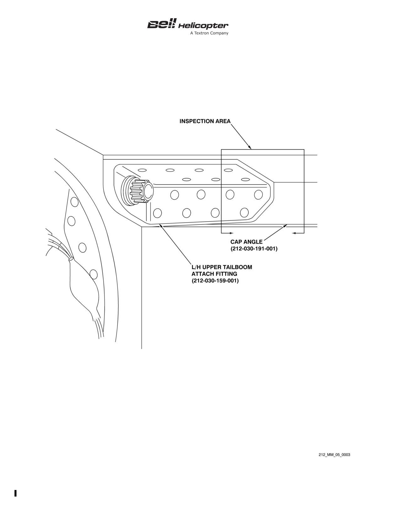
attachment fitting and cap angle (Figure 5-1).
3.
Move pylon fore and aft. Using mast as lever, check friction
dampers for freedom of movement and smooth operation.
4.
Inspect transmission mounts, mounting brackets, and
structure for cracked or broken parts.
5.
Inspect lift link and fitting for cracks and security.
6.
Cabin interior and exterior for corrosion and damage.
7.
All compartments for evidence of water entrapment and
corrosion.
8.
Ensure all drain holes are open.
9.
Inspect underside of fuselage:
a. Fuselage structure for damage, corrosion, and working
rivets.
b. Exterior finish for condition and cleanliness.
c. Evidence of excessive fluid leakage.
d. Structure around landing gear for condition.
e. Forward crosstube support structure for working
fasteners, cracks, corrosion, and excessive wear.
f. Aft crosstube support structure for working fasteners,
cracks, corrosion, and excessive wear.
10. Fuselage bonded panels for damage and delamination.
11. Cabin roof structure:
5-00-00
Page 36
Rev. 18
15 MAY 2020
Export Classification C, ECCN EAR99
BHT-212-MM-1
SCHEDULED INSPECTIONS
5-9.
100 HOURS/12 CALENDAR MONTHS - PART A (CONT)
INITIAL
DATA REFERENCE
INSPECTION TASK DESCRIPTION
MECH OTHER
a. Cabin roof structure, cowlings, and fairings for damage,
delamination, and general condition.
b. Cabin roof and cowling/fairing mounted antennas for
condition and security.
Every sixth 100 hour inspection (600 hours) or 12 months:
1.
Fuselage cabin structure:
a. Fuselage structure for corrosion and damage to finish
and sealant. Pay particular attention to edges of joints and
seams and around fastener heads.
b. Engine compartment floor and service deck at
FS 155.06 to 241.22 for damage, delamination, and corrosion.
NOTE
To adequately inspect the following, it will be
necessary to remove the auxiliary fuel tanks if
installed.
2.
Pylon wall for damage, working fasteners, cracks,
delamination, and corrosion.
CENTER FUSELAGE
Lower cyclic hydraulic actuator supports 212-030-286-001 and
-002 in cargo hook compartment (hellhole).
NOTE
Inspection is not applicable to helicopter S/N 30790
and subsequent and helicopters modified in
accordance with TB 212-76-12.
1.
Clean area around fuel vent line hole with MEK (C-309) or
equivalent and remove finish from beam cap.
2.
Inspect each beam cap for hairline cracks using a bright
light. Inspect inboard side of left and right main beams around
fuel vent line that goes through cap extrusion at FS 131.00,
WK 21.50, and BL 14.00. Pay particular attention to first high
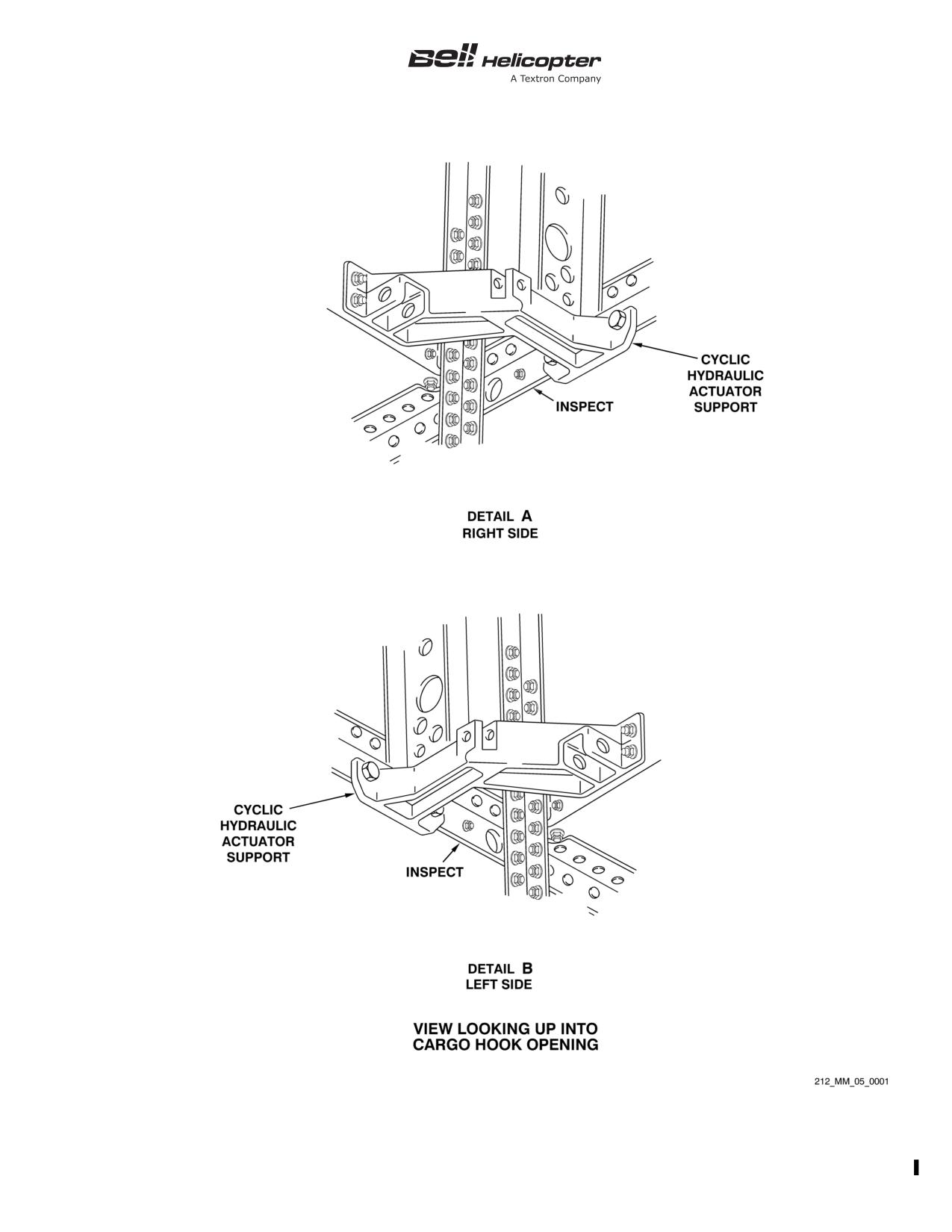
shear rivet hole above WL 22.00 at FS 129.00 (Figure 5-2,
Detail A and Detail B).
5-00-00
Export Classification C, ECCN EAR99
15 MAY 2020 Rev. 18
Page 37
BHT-212-MM-1
SCHEDULED INSPECTIONS
5-9.
100 HOURS/12 CALENDAR MONTHS - PART A (CONT)
INITIAL
DATA REFERENCE
INSPECTION TASK DESCRIPTION
MECH OTHER
3.
Apply clear lacquer over cleaned area.
Chapter 62
MAIN ROTOR BLADE INSPECTION SYSTEM (BIS)
- Inspect
BHT-212-CR&O
1.
Test detector unit.
and Chapter 96
2.
Perform continuity check on blade conductor circuits.
3.
Remove BIS battery.
4.
Perform battery condition check on replacement battery.
Install replacement battery.
Chapter 62
MAIN ROTOR BLADES
1.
Wash main rotor blades with mild soap and water. Rinse
and dry thoroughly.
- Detailed Visual Inspection
2.
Main rotor blades upper and lower surfaces for condition of
bond lines, doublers, and leading edge for erosion. Inspect
blade surfaces for corrosion, cracks, damage, and voids.
Chapter 62
MAIN ROTOR HUB
- Detailed Visual Inspection
1.
Main rotor hub assembly (grips, drag braces, trunnion,
pillow blocks, static stops, and mast nut) for condition and
security.
2.
Hub assembly for proper oil level or grease lubrication.
3.
Main rotor yoke for evidence of cracks at pillow block
bushing bores. Proper sealing of pillow blocks, yoke, and
attaching through bolts, washers, nuts, and bushings.
4.
Inspect blade retention bolts for condition and security.
5-00-00
Page 38
Rev. 18
15 MAY 2020
Export Classification C, ECCN EAR99
BHT-212-MM-1
SCHEDULED INSPECTIONS
5-9.
100 HOURS/12 CALENDAR MONTHS - PART A (CONT)
INITIAL
DATA REFERENCE
INSPECTION TASK DESCRIPTION
MECH OTHER
Chapter 62
MAIN ROTOR CONTROLS
1.
Swashplate and support assembly:
a. Inspect for condition and security with special attention
to gimbal ring attachment lugs.
NOTE
The presence of black oxide powder will require
investigation to determine the cause.
b. Inspect gimble ring bearings, liners, and attaching
hardware for excessive looseness and wear. Gimble ring
bearing and attaching bolt axial or radial looseness shall not
exceed 0.005 inch (0.127 mm) and no binding is allowed.
2.
Disconnect flight control tubes from swashplate and
collective lever assembly. Inspect six trunnion bearings
204-011-451-001 for 0.020 inch (0.508 mm) maximum axial
play. Rotate bearings 180° and purge lubricate.
3.
Inspect collective levers for condition and evidence of
corrosion, and scissors and sleeve assembly for security and
condition.
4.
Inspect stabilizer bar dampers clamps for condition and
evidence of corrosion.
5.
Inspect stabilizer bar assembly for condition and security.
Pay particular attention to tubes P/N 204-011-328-001 and -011
for cracks. Closely inspect area covering 360°, 1.5 inches
(38.1 mm) outboard from vertical bolt.
6.
Replace bearings MS20201KP8A or MS27641-8 in
scissors levers 204-011-406.
7.
Replace bearings AN204KP6A or MS27641-6 in mixing
levers 204-011-301.
Chapter 63
TRANSMISSION
1.
Inspect mounts for damage and security. Check boots for
condition and ensure boots are in place.
5-00-00
Export Classification C, ECCN EAR99
15 MAY 2020 Rev. 18
Page 39
BHT-212-MM-1
SCHEDULED INSPECTIONS
5-9.
100 HOURS/12 CALENDAR MONTHS - PART A (CONT)
INITIAL
DATA REFERENCE
INSPECTION TASK DESCRIPTION
MECH OTHER
2.
Inspect lift link and attachments for corrosion, damage, and
security. Check bearings for looseness.
3.
Inspect for evidence of oil leakage.
4.
Check all transmission chip detectors for debris and then
clean.
5.
Test all transmission chip detectors electrical circuits.
6.
Refer to Special Inspection paragraph 5-25, paragraph
5-27 and paragraph 5-34 (as applicable) for transmission oil
change and internal oil filter or full flow debris monitor inspection
requirements.
7.
Every third 100 hour inspection (300 hours), torque check
top case to ring gear case nuts, ring gear case to main case
nuts, and main case to support case nuts
230 to
250
inch-pounds (25.99 to 28.25 Nm). Retorque as required.
Chapter 63
MAIN ROTOR MAST
- Detailed Visual Inspection
1.
Inspect mast assembly for security, corrosion, and
mechanical damage. Pay particular attention to area contacted
by main rotor hub static stops, and damper assembly/adapter
set splines.
2.
Inspect for evidence of oil leaks at mast bearing cap.
5-00-00
Page 40
Rev. 18
15 MAY 2020
Export Classification C, ECCN EAR99
BHT-212-MM-1
SCHEDULED INSPECTIONS
5-9.
100 HOURS/12 CALENDAR MONTHS - PART A (CONT)
INITIAL
DATA REFERENCE
INSPECTION TASK DESCRIPTION
MECH OTHER
Chapter 64
TAIL ROTOR HUB AND BLADE ASSEMBLY
CAUTION
COUNTERWEIGHT BELLCRANK RETENTION
NUTS P/N MS14145L6 OR ITS EQUIVALENT
MS17826-6 ARE DESIGNATED AS ONE TIME USE
ONLY. IF MAINTENANCE ACTION REQUIRES
THAT IT BE REMOVED, THE COUNTERWEIGHT
BELLCRANK NUT IS TO BE DISCARDED AND
REPLACED WITH A NEW NUT. OVERTORQUING
OR INCORRECT APPLICATION OF THE NUT
COULD CAUSE MECHANICAL FAILURE
RESULTING IN EXCESSIVE VIBRATION OR
DAMAGE TO THE TAIL ROTOR BLADES.
1.
Inspect the tail rotor counterweight bellcrank (P/N
212-011-705-001) retention nuts for cracks, corrosion, and
security. Reapply corrosion preventive compound (C-101) if
nuts are not completely covered.
Every third 100 hour inspection (300 hours) or every 12
months:
Chapter 18
1.
Dynamically balance tail rotor.
2.
Torque check nuts on tail rotor blade retention bolts.
3.
Torque check tail rotor retaining nut.
Chapter 65
TAIL ROTOR GEARBOX
1.
Inspect chip detector for debris. If metallic particles are
found, determine and correct cause.
2.
Clean chip detector.
3.
Test chip detector electrical circuit.
Chapter 65
TAIL ROTOR DRIVESHAFT
1.
Hanger assemblies for cracks at mounting ears, corrosion,
and security of attachment.
5-00-00
Export Classification C, ECCN EAR99
15 MAY 2020 Rev. 18
Page 41
BHT-212-MM-1
SCHEDULED INSPECTIONS
5-9.
100 HOURS/12 CALENDAR MONTHS - PART A (CONT)
INITIAL
DATA REFERENCE
INSPECTION TASK DESCRIPTION
MECH OTHER
2.
Hanger supports for condition and security of attachment.
3.
Driveshaft sections and attaching hardware for condition
and security.
a. Condition of clamps for tail rotor driveshaft coupling to
gearbox couplings (90° apart).
b. Inspect clamps for cracks in or near the bolt hole lugs.
Chapter 65
INTERMEDIATE GEARBOX
1.
Inspect chip detector for debris. If metallic particles are
found, determine and correct cause.
2.
Clean chip detector.
3.
Test chip detector electrical circuit.
Chapter 67
ELEVATOR
- Detailed Visual Inspection
1.
Elevators for security, cracks, damage, loose or missing
rivets, and corrosion.
2.
Check elevator attachment lugs at each end of elevator
horn for cracks and security of attachment. Check elevator horn
to elevator spar attaching bolts and surrounding joints for cracks
and security of attachment.
Every third 100 hour inspection (300 hours) or 12 months:
1.
Check left and right elevator assemblies for excessive axial
and radial play using a dial indicator mounted on the tailboom,
with stylus touching inboard edge of elevator near attachment
bolt for axial measurement, and touching upper surface near
attachment bolt for radial measurement. Applying light force to
move elevator in required direction, check that radial movement
does not exceed
0.010 inch
(0.254 mm), and that axial
movement is within 0.005 to 0.030 inch (0.127 to 0.762 mm).
Adjust shims as required.
2.
Elevator rigging for proper setting and travel.
5-00-00
Page 42
Rev. 18
15 MAY 2020
Export Classification C, ECCN EAR99
BHT-212-MM-1
SCHEDULED INSPECTIONS
5-9.
100 HOURS/12 CALENDAR MONTHS - PART A (CONT)
INITIAL
DATA REFERENCE
INSPECTION TASK DESCRIPTION
MECH OTHER
3.
Check elevator horn for security, mechanical damage, and
corrosion.
4.
Trailing edge tabs and tip caps for condition and security.
Every sixth 100 hour inspection (600 hours) or 12 months:
1.
Remove left and right elevators.
2.
Clean elevator spars and inspect for corrosion.
3.
Clean internal bore of elevator horn and inspect for
corrosion.
4.
With elevator control removed, attach a spring scale to
hole in arm of horn where control tube is normally installed. Pull
scale at right angle to arm, verify friction is 26 to 32 pounds
(115.65 to 142.34 N). If friction is not within limits, adjust shim
thickness.
5.
Install left and right elevators.
Chapter 67
FLIGHT CONTROLS
- Detailed Visual Inspection
1.
Inspect all control tube assemblies for clearances, security,
and general condition, paying particular attention to tail rotor
and elevator control tubes for chafing and wear (maximum
allowable wear 0.008 inch (0.2032 mm)).
2.
Control tube bellcranks, supports, and attaching hardware
for corrosion, security, wear, and damage.
Every sixth 100 hour inspection (600 hours) or 12 months:
1.
Collective flight controls:
a. Flight control systems bellcrank and control tubes for
damage, chafing, corrosion, and security of attachment.
b. Friction shoes and liners for condition.
c. Check collective lever friction adjuster for operation.
5-00-00
Export Classification C, ECCN EAR99
15 MAY 2020 Rev. 18
Page 43
BHT-212-MM-1
SCHEDULED INSPECTIONS
5-9.
100 HOURS/12 CALENDAR MONTHS - PART A (CONT)
INITIAL
DATA REFERENCE
INSPECTION TASK DESCRIPTION
MECH OTHER
d. Check for proper collective minimum friction.
e. Check collective flight controls for smooth movement
throughout full range of travel.
2.
Cyclic flight controls:
a. Flight control systems bellcrank and control tubes for
damage, chafing, corrosion, and security of attachment.
b. Check cyclic stick friction adjuster for proper operation.
c. Check for proper cyclic minimum friction (applicable to
AFCS equipped helicopters).
d. Check cyclic flight controls for smooth movement
throughout full range of travel.
3.
Anti-torque flight controls:
a. Flight control systems bellcrank and control tubes for
damage, chafing, corrosion, and security of attachment.
b. Check anti-torque friction adjuster for proper friction.
c. Check anti-torque flight controls for smooth movement
throughout full range of travel.
Chapter 67
COLLECTIVE AND CYCLIC FLIGHT CONTROL
ACTUATORS
- Detailed Visual Inspection
1.
Universal bearings for looseness.
2.
Input lever bearings and bolts for wear and looseness.
3.
Fasteners attaching cylinder lower supports to structure for
looseness.
4.
Cylinder lower bearings for looseness.
5.
Actuator assemblies for condition, leakage, and security.
5-00-00
Page 44
Rev. 18
15 MAY 2020
Export Classification C, ECCN EAR99
BHT-212-MM-1
SCHEDULED INSPECTIONS
5-9.
100 HOURS/12 CALENDAR MONTHS - PART A (CONT)
INITIAL
DATA REFERENCE
INSPECTION TASK DESCRIPTION
MECH OTHER
6.
Cylinder extension tubes for condition and security.
7.
Upper cylinder housing mounting bracket for condition and
security. Check mounting bracket cavity for corrosion. Cavity
drain hole for obstruction. Dust boot for condition. Reapply
corrosion preventive compound (C-104) as required.
8.
Actuator linkage for wear and security.
9.
Clean exposed area of actuator piston with hydraulic fluid
(C-002) or hydraulic fluid (C-072) and a clean lint-free cloth.
10. Check cyclic and collective hydraulic cylinders piston rods
for evidence of excessive wear and scoring. Wear of the piston
rods indicates cylinder assembly is incorrectly aligned to lower
supports and requires adjustment.
Chapter 67
- Restoration
Every third 100 hour inspection (300 hours) or 12 months:
1.
Torque check nuts attaching actuator cylinder to upper
supports.
2.
Remove bolts attaching actuator to lower supports. Check
cylinder alignment to lower support. Rod end bearing side loads
are not permitted. Reinstall bolts.
TAIL ROTOR FLIGHT CONTROL ACTUATOR
1.
Tail rotor hydraulic actuator for leaks and security of
attachment, mechanical damage, corrosion, and bearings and
linkages for looseness.
Chapter 71
POWER PLANT
Every third 100 hour inspection (300 hours) or 12 months:
NOTE
If applicable, refer to BHT-212-SI-96 for installation
of adjustable seals or refer to Chapter 71 for seal
adjustment.
5-00-00
Export Classification C, ECCN EAR99
15 MAY 2020 Rev. 18
Page 45
BHT-212-MM-1
SCHEDULED INSPECTIONS
5-9.
100 HOURS/12 CALENDAR MONTHS - PART A (CONT)
INITIAL
DATA REFERENCE
INSPECTION TASK DESCRIPTION
MECH OTHER
ASB 212-10-137
1.
Inspect the left-hand and right-hand engine air inlet
cowlings for gaps between the lower surface of the cowling
firewall and the mating horizontal engine firewall.
Chapter 71
LEFT POWER SECTION
NOTE
Refer to Pratt & Whitney Canada PT6T-3/-3B
Maintenance Manual for engine inspection
requirements.
Every third 100 hour inspection (300 hours) or 12 months:
- Detailed Visual Inspection
1.
Ignition leads for corrosion, chafing and security.
2.
Chip detectors for debris.
- Restoration
1.
Clean chip detectors.
- Functional Check
1.
Test chip detectors electrical circuits.
RIGHT POWER SECTION
NOTE
Refer to Pratt & Whitney Canada PT6T-3/-3B
Maintenance Manual for engine inspection
requirements.
Every third 100 hour inspection (300 hours) or 12 months:
- Detailed Visual Inspection
1.
Ignition leads for corrosion, chafing and security.
2.
Chip detectors for debris.
5-00-00
Page 46
Rev. 18
15 MAY 2020
Export Classification C, ECCN EAR99
BHT-212-MM-1
SCHEDULED INSPECTIONS
5-9.
100 HOURS/12 CALENDAR MONTHS - PART A (CONT)
INITIAL
DATA REFERENCE
INSPECTION TASK DESCRIPTION
MECH OTHER
- Restoration
1.
Clean chip detectors.
- Functional Check
1.
Test chip detectors electrical circuits.
Chapter 76
ENGINE FUEL AND POWER CONTROLS
Every third 100 hour inspection (300 hours) or 12 months:
- Operational Check
1.
Check controls for smooth movement through full travel
ranges.
BHT-212-FM-1
2.
Check engine fuel control.
Chapter 71
STARTER GENERATOR
Every third 100 hour inspection (300 hours) or 12 months.
- Detailed Visual Inspection
1.
Left power section starter generator cooling ducts for
obstruction, kinking, and security.
2.
Right power section starter generator cooling ducts for
obstruction, kinking, and security.
3.
Left power section starter generator brushes for allowable
wear.
4.
Right power section starter generator brushes for allowable
wear.
Chapter 76
ENGINE CONTROLS
1.
Deleted.
5-00-00
Export Classification C, ECCN EAR99
15 MAY 2020 Rev. 18
Page 47
BHT-212-MM-1
SCHEDULED INSPECTIONS
5-9.
100 HOURS/12 CALENDAR MONTHS - PART A (CONT)
INITIAL
DATA REFERENCE
INSPECTION TASK DESCRIPTION
MECH OTHER
Every third 100 hour inspection (300 hours) or 12 months:
1.
Engine fuel and power controls:
a. Engine control linkages for looseness, lost motion,
chafing, damage, and security of attachment.
b. Bellcranks, mounts, and jackshafts for looseness,
damage, and security of attachment.
Every sixth 100 hour inspection (600 hours) or 12 months:
1.
Perform maximum NG topping check.
Chapter 71
COMBINING (REDUCTION) GEARBOX
NOTE
Refer to Pratt & Whitney Canada PT6T-3/-3B
Maintenance Manual for engine inspection
requirements.
Every third 100 hour inspection (300 hours) or 12 months:
- Detailed Visual Inspection
1.
Chip detectors for debris.
- Restoration
1.
Clean chip detectors.
- Functional Check
1.
Test chip detectors electrical circuits.
Chapter 95
INSTRUMENTS
NOTE
The following checks are required every 12 months
only.
5-00-00
Page 48
Rev. 18
15 MAY 2020
Export Classification C, ECCN EAR99
BHT-212-MM-1
SCHEDULED INSPECTIONS
5-9.
100 HOURS/12 CALENDAR MONTHS - PART A (CONT)
INITIAL
DATA REFERENCE
INSPECTION TASK DESCRIPTION
MECH OTHER
1.
Calibrate pilot and copilot compass systems and standby
magnetic compass.
2.
Drain pitot-static system of any accumulated moisture.
3.
Test pitot-static system for leaks.
Chapter 96
ELECTRICAL SYSTEM
1.
Check inverters for security of mounting and connections.
2.
Check generator control units for damage and security of
mounting and terminals.
3.
All exposed wire bundles, bundle supports and connectors
for damage, corrosion, and security. Pay particular attention to
engine deck connectors and harnesses.
4.
Inspect relays and main bus area for security of mounting
and connections.
5.
Inspect bus insulation for damage and condition.
6.
Deleted.
Chapter 96
BATTERY SYSTEM
1.
Deleted.
2.
Inspect battery compartment for general condition.
3.
Check battery mount for security and corrosion.
Chapter 96
POWER DIODES
Every third 100 hour inspection (300 hours) or 12 months:
1.
Perform functional check of power diodes.
5-00-00
Export Classification C, ECCN EAR99
15 MAY 2020 Rev. 18
Page 49
BHT-212-MM-1
Figure 5-1. Fuselage Tailboom Attachment Inspection
5-00-00
Page 50
Rev. 14
26 JUN 2013
Export Classification C, ECCN EAR99
BHT-212-MM-1
Figure 5-2. Inspection of Beam Caps
5-00-00
Export Classification C, ECCN EAR99
26 JUN 2013 Rev. 14
Page 51/52
BHT-212-MM-1
SCHEDULED INSPECTIONS
5-10.
1000 HOURS - PART A
INITIAL
DATA REFERENCE
INSPECTION TASK DESCRIPTION
MECH OTHER
DATE:
__________________
W.O.
_____________________
FACILITY:
_________________________________________
HELICOPTER S/N:
__________________________________
REGISTRY NO.:
____________________________________
TOTAL TIME:_______________________________________
SIGNATURE:_______________________________________
NOTE
For helicopters on the Part A inspection program,
accomplish the following checks each 1000 hours of
flight operation.
GENERAL
- Instruction
1.
Each listed inspection item or maintenance function is to
be performed in accordance with this Maintenance Manual.
2.
All work accomplished during the inspection shall be
recorded in the helicopter maintenance record.
3.
Deleted.
Chapter 12
4.
Refer to Lubrication Chart (Chapter 12) for 1000 hour
requirements.
Chapter 62
SWASHPLATE AND SUPPORT ASSEMBLY - SCISSORS
AND SLEEVE ASSEMBLY
1.
Inspect swashplate and support assembly, and scissors
and sleeve assembly.
5-00-00
Export Classification C, ECCN EAR99
15 MAY 2020 Rev. 18
Page 53
BHT-212-MM-1
SCHEDULED INSPECTIONS
5-10.
1000 HOURS - PART A (CONT)
INITIAL
DATA REFERENCE
INSPECTION TASK DESCRIPTION
MECH OTHER
2.
Disconnect bottom of each drive link from swashplate
trunnion and each mixing lever control tube from scissors.
3.
Check swashplate duplex bearing and collective sleeve
hub bearing set for roughness and ease of rotation.
4.
Purge lubricate bearings.
5.
Reconnect drive links and tubes.
5-00-00
Page 54
Rev. 14
26 JUN 2013
Export Classification C, ECCN EAR99
BHT-212-MM-1
SCHEDULED INSPECTIONS
5-11.
5000 HOURS/5 YEARS INSPECTION - PART A
INITIAL
DATA REFERENCE
INSPECTION TASK DESCRIPTION
MECH OTHER
DATE:
__________________
W.O.
_____________________
FACILITY:
_________________________________________
HELICOPTER S/N:
__________________________________
REGISTRY NO.:
____________________________________
TOTAL TIME:_______________________________________
SIGNATURE:_______________________________________
NOTE
For helicopters on the Part A inspection program,
accomplish each
5000 hours flight time or
60
months, whichever comes first.
This inspection is meant to be a full visual inspection
of the airframe primarily for environmental damage
and corrosion.
GENERAL
Each listed inspection item or maintenance function is to be
performed in accordance with the BHT-212-MM chapter
specified or the BHT-212-CR&O.
PRELIMINARY REQUIREMENTS
1.
All work accomplished during this inspection shall be
recorded in the helicopter maintenance records.
2.
Remove all panels, interior coverings, fairings, and
cowlings required to satisfactorily carry out the inspection.
3.
Remove the following items:
Chapter 96
a. Main battery.
Chapter 97
b. Electrical and avionics equipment from the nose area,
as required, to allow a full visual inspection of the nose area to
be done.
5-00-00
Export Classification C, ECCN EAR99
15 MAY 2020 Rev. 18
Page 55
BHT-212-MM-1
SCHEDULED INSPECTIONS
5-11.
5000 HOURS/5 YEARS INSPECTION - PART A (CONT)
INITIAL
DATA REFERENCE
INSPECTION TASK DESCRIPTION
MECH OTHER
Chapter 62
c. Main rotor transmission.
Chapter 65
d. Intermediate gearbox.
Chapter 64
e. Tail rotor gearbox.
Chapter 53
f. Tailboom (to allow a full inspection of the aft fuselage
bulkhead and forward tailboom bulkhead).
Chapter 32
g. Landing gear assembly (to allow a complete inspection
of the landing gear attachment points and support structure).
4.
In addition to the 5000 Hour/5 Year Inspection - Part A
items, carry out the following:
a. Complete Daily Inspection - Part A.
b. Complete 100 Hour/12 Month Inspection - Part A.
c. Complete 1000 Hour Inspection - Part A.
AFTER COMPLETION OF INSPECTION
1.
Install the following items:
Chapter 96
a. Main battery.
Chapter 97
b. Electrical and avionics equipment on the nose area.
Chapter 62
c. Main rotor transmission.
Chapter 65
d. Intermediate gearbox.
Chapter 64
e. Tail rotor gearbox.
Chapter 53
f. Tailboom.
Chapter 32
g. Landing gear assembly.
2.
Install all panels, interior coverings, fairings, and cowlings
removed during inspection.
5-00-00
Page 56
Rev. 18
15 MAY 2020
Export Classification C, ECCN EAR99
BHT-212-MM-1
SCHEDULED INSPECTIONS
5-11.
5000 HOURS/5 YEARS INSPECTION - PART A (CONT)
INITIAL
DATA REFERENCE
INSPECTION TASK DESCRIPTION
MECH OTHER
3.
Do a ground run and leak check before you return the
helicopter to service.
Chapter 53
FORWARD FUSELAGE
1.
Nose panels in area of pitot tube attachment, areas inside
and outside for disbonding and cracking.
2.
Pitot tubes attachment for looseness.
3.
Nose shelves for damage, corrosion, and disbonding.
4.
Nose shelf attachment locations for damage, corrosion,
and cracking.
5.
Right and left BL 14.00 main beams, forward of STA 23.00
for damage, corrosion, and cracking.
6.
Instrument panel attachment structure for damage,
corrosion, and cracking, primarily in the door frame attachment
area.
7.
Instrument panel glareshield for chafing and cracking.
8.
Crew door hinge attachment structure for damage and
cracks.
9.
Outboard cabin post
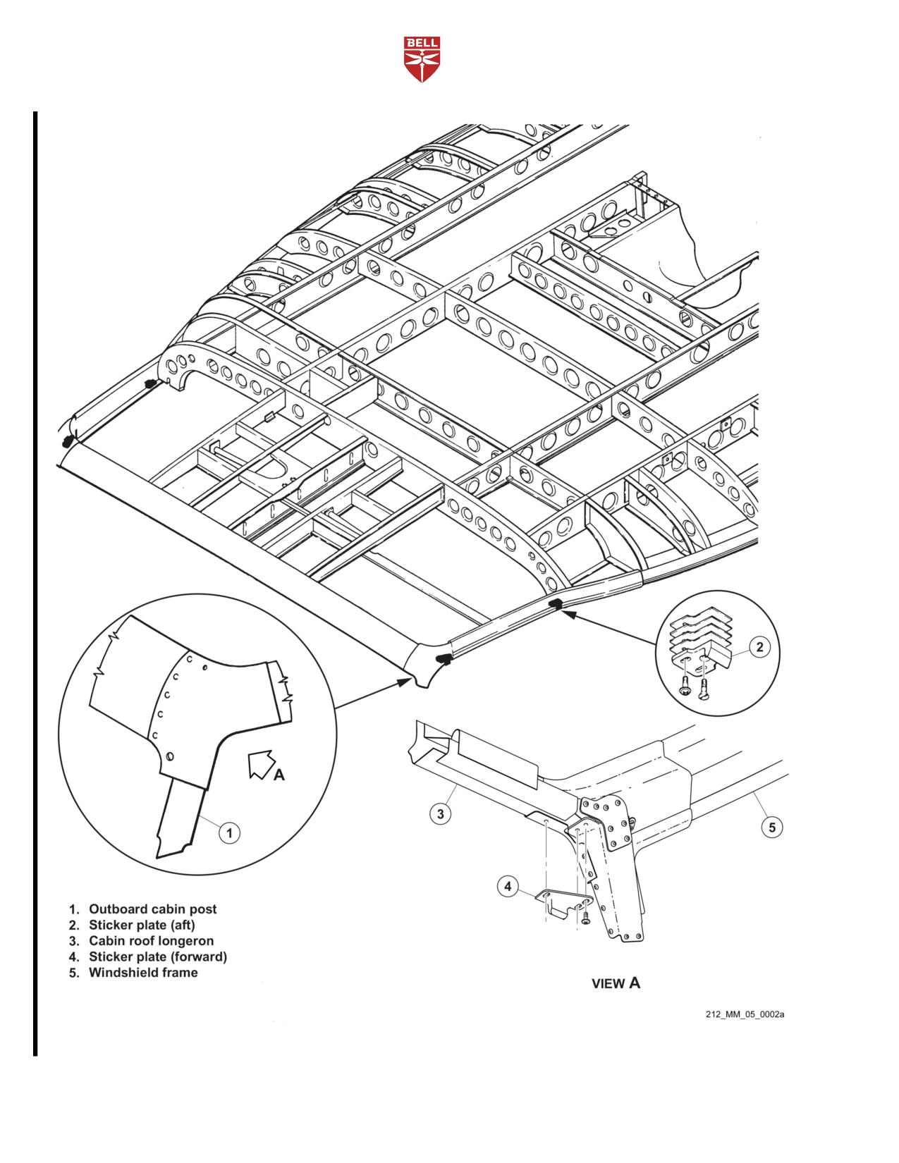
(1, Figure
5-2A), cabin roof
longeron (2), and windshield frame (5) upper corner area for
damage and cracks.
10. Striker plates (3 and 4) attachment areas for damage and
cracks.
11. Striker plates (3 and 4) for excessive wear, damage, and
corrosion.
12. Cabin floor area under crew doors for chafing and damage.
13. Crew door hinges for wear, damage, corrosion, and
security of attachment.
14. Crew doors for proper fit and operation.
5-00-00
Export Classification C, ECCN EAR99
15 MAY 2020 Rev. 18
Page 57
BHT-212-MM-1
SCHEDULED INSPECTIONS
5-11.
5000 HOURS/5 YEARS INSPECTION - PART A (CONT)
INITIAL
DATA REFERENCE
INSPECTION TASK DESCRIPTION
MECH OTHER
15. Crew seat rails for excessive wear and damage.
16. Center and outboard bulkhead, below WL 22.00 at FS
23.00, for cracks, deformation, and corrosion along structure
joints.
17. Collective and cyclic control jackshafts support intercostals
for cracks and corrosion.
18. Cyclic support for corrosion and cracks.
19. Collective, cyclic, and antitorque control system bellcranks,
levers, and support brackets for corrosion, cracks, and
indication of wear at attaching points.
20. Crew seat support beams, at BL 14.00 and 30.00 between
FS 23.00 and 74.30, for cracks and corrosion.
21. Forward crosstube attachment points and support structure
at FS 63.33 and 74.30 for damage, corrosion, and cracks.
22. Aft crosstube attachment points and support structure at
FS 155.06 and 166.00 for damage, corrosion, and cracks.
23. Crew and passenger cabin floor, FS 23.00 to 155.06, for
corrosion and damage. Floor bonded panels for voids. Seat
fasteners and cargo tie-down rings for condition. Area around
pilot and copilot ICS foot switches for cracks.
NOTE
In the following step, removal of the fuel cells is not
required unless there is evidence of fuel leakage or
damage to the fuel cells or structure is suspected.
24. All structure under floor panels and in forward fuel cell
cavities including caps, angles, transverse bulkheads, and
bonded panels between FS 74.30 and 155.06 for damage,
corrosion, cracks, and voids.
5-00-00
Page 58
Rev. 18
15 MAY 2020
Export Classification C, ECCN EAR99
BHT-212-MM-1
SCHEDULED INSPECTIONS
5-11.
5000 HOURS/5 YEARS INSPECTION - PART A (CONT)
INITIAL
DATA REFERENCE
INSPECTION TASK DESCRIPTION
MECH OTHER
NOTE
In the following step, removal of the fuel cells is not
required unless there is evidence of fuel leakage or
damage to the fuel cells or structure is suspected.
Structure that is hidden by the fuel cells only needs
to be inspected if the fuel cells are removed for some
reason or structural damage is suspected.
25. All structure under floor panels and in aft fuel cell cavities
including caps, angles, and panels between FS 155.06 and
200.00 for damage, corrosion, cracks, and disbonding.
26. Bottom skin, FS 23.00 to 243.937, for damage. Joints for
corrosion. Access panels and covers for condition and
attachment.
27. Main transmission compartment interior, FS 129.00 to
166.00 and WL 7.44 to 76.00, for corrosion. Bulkheads and
main beam panels for damage and corrosion. Attaching
supports and brackets for condition and security.
28. Fluid lines in transmission compartment for evidence of
leaks, condition, wear, and chafing. Clamps for condition (fluid
contamination and swelling) and security of attachment.
29. Lift beam fitting for condition and working rivets, lift link
attachment bolt hole bores for excessive wear, and bushings for
looseness.
30. Pylon (transmission) support structure for wear and cracks.
Pay particular attention to right and left horizontal supports,
forward vertical supports, and aft vertical webs.
31. Aft cabin bulkheads, FS 166.00, for damage, upper aft
flange for cracks, and bulkhead panel for damage and
disbonding.
32. Electrical/avionics compartment, FS 166.00 to 243.937,
doors for condition and security. Door frames for cracks and
corrosion. Compartment interior for condition and joints for
corrosion. Skin for damage and cracks.
5-00-00
Export Classification C, ECCN EAR99
15 MAY 2020 Rev. 18
Page 59
BHT-212-MM-1
SCHEDULED INSPECTIONS
5-11.
5000 HOURS/5 YEARS INSPECTION - PART A (CONT)
INITIAL
DATA REFERENCE
INSPECTION TASK DESCRIPTION
MECH OTHER
33. Oil cooler compartment, FS 166.00 to 243.937, doors for
condition and security. Main beam panels and bulkheads for
condition and corrosion.
34. Engine deck below the reduction gearbox, FS 211.00 to
238.00 for damage, cracks, and disbonding.
35. Firewalls, FS
155.06 to
241.22, for damage, cracks,
security of attachment, seals for condition, and seal attachment
angles for cracks.
36. Cabin roof, FS 35.00 to 166.00 above WL 68.00, BL 50.00
left and right side, for damaged skin and joints for corrosion,
bonded panels for disbonding and corrosion. Structure above
overhead console (circuit breaker panels) for cracks and
corrosion.
37. Cargo door tracks for wear, cracks, and corrosion.
38. Engine and transmission cowlings and fairings for
evidence of chafing, cracks, corrosion, and seals for condition.
39. Bulkhead, FS 241.22, for damage, corrosion, and cracks.
Tailboom attachment fittings for damage, cracks, and loose
fasteners. Tailboom attachment bolt holes for damage and
corrosion.
40. Tailboom attachment bolts for damage, wear, and
corrosion.
Chapter 53
TAILBOOM
1.
Bulkhead, BS 17.42, for corrosion and cracks. Fuselage
attachment bolt holes for damage and corrosion. Barrel nuts for
damage and corrosion.
2.
Tailboom and fin driveshaft covers for condition and
attachment.
3.
Tailboom and fin external skin for damage, corrosion, and
cracks.
4.
Tailboom access panels and covers for condition and
attachment. Tail rotor driveshaft cover hinges for wear.
5-00-00
Page 60
Rev. 18
15 MAY 2020
Export Classification C, ECCN EAR99
BHT-212-MM-1
SCHEDULED INSPECTIONS
5-11.
5000 HOURS/5 YEARS INSPECTION - PART A (CONT)
INITIAL
DATA REFERENCE
INSPECTION TASK DESCRIPTION
MECH OTHER
5.
Tailboom baggage compartment door for condition,
attachment, and door handle operation.
6.
Tailboom baggage compartment interior for damage,
panels for disbonding, and corrosion. Longerons above roof
panel for corrosion and cracks. Longerons below floor panel for
corrosion and cracks.
7.
Tailboom interior bulkheads and stringers for cracks and
corrosion.
8.
Intermediate gearbox mount pad for damage, cracks,
fretting, and corrosion.
9.
Tail rotor gearbox support fitting assembly for damage,
cracks, fretting, and corrosion. Pay particular attention to
mounting holes and lugs.
10. Tailboom exterior bonded panels adjacent to baggage
compartment for damage, delamination, and corrosion.
11. With a borescope or equivalent, inspect interior structure of
vertical fin for cracks, corrosion, fretting, and damage.
12. Control tube fairleads (grommets and guides) for wear and
security of attachment.
5-00-00
Export Classification C, ECCN EAR99
15 MAY 2020 Rev. 18
Page 60A
BHT-212-MM-1
Figure 5-2A. Cabin Frame Inspection - Part A
5-00-00
Page 60B
Rev. 18
15 MAY 2020
Export Classification C, ECCN EAR99
BHT-212-MM-1
SCHEDULED INSPECTIONS
5-12.
25 HOURS/30 DAYS - PART B
INITIAL
DATA REFERENCE
INSPECTION TASK DESCRIPTION
MECH OTHER
DATE:
__________________
W.O.
_____________________
FACILITY:
_________________________________________
HELICOPTER S/N:
__________________________________
REGISTRY NO.:
____________________________________
TOTAL TIME:_______________________________________
SIGNATURE:_______________________________________
NOTE
For helicopters on the Part B inspection program,
accomplish the following checks each 25 hours of
flight operation or 30 days, whichever occurs first.
GENERAL
1.
Each listed inspection item or maintenance function is to
be performed in accordance with the referenced Maintenance
Manual chapter specified or BHT-212-CR&O manual.
2.
Refer to Pratt & Whitney Canada PT6T-3/-3B Maintenance
Manual for engine inspection requirements.
PRELIMINARY REQUIREMENTS
CSSD-PSE-87-001
1.
Use medium helicopter corrosion control guide to establish
helicopter corrosion control program.
Chapter 4
2.
Replace all finite life components that have completed
published operating limitations.
Chapter 5
3.
Overhaul all components that have completed published
overhaul periods.
Chapter 12
4.
Lubricate and service helicopter as required.
5-00-00
Export Classification C, ECCN EAR99
26 JUN 2013 Rev. 14
Page 61
BHT-212-MM-1
SCHEDULED INSPECTIONS
5-12.
25 HOURS/30 DAYS - PART B (CONT)
INITIAL
DATA REFERENCE
INSPECTION TASK DESCRIPTION
MECH OTHER
Chapter 5
5.
Review Special Inspections and carry out applicable
inspections.
6.
Examine all inspection windows and sight glasses for
cracking, crazing, and discoloration. If any of these conditions
are present the part must be removed and replaced prior to
returning helicopter to service.
Service Instructions
7.
Make sure that all the required inspections of installed BHT
(SI)
kits are not covered in this inspection have been performed, as
applicable.
FUSELAGE - NOSE SECTION
Chapter 95
1.
Pitot tubes and static ports for visible obstruction and
damage.
Chapter 52
2.
Nose doors for damage, corrosion, security of attachment,
and missing or damaged twist fasteners, seal for condition.
Chapter 53
3.
Fuselage:
a. Forward fuselage area structure and skin for damage,
corrosion, cleanliness, and damage to protective finish.
b. Avionics and electrical compartment for water
entrapment.
Chapter 96
4.
Battery installation:
a. Battery and external connections for security, corrosion,
and condition.
b. Battery vent and drain tubes are unobstructed.
c. Every fourth 25 hour/30 day inspection (100 hours)
check battery mounts for corrosion and service battery in
accordance with battery manufacturer’s recommendation.
Chapter 96
5.
Electrical equipment for condition, corrosion, and security.
Chapter 97
6.
Avionics equipment for condition and security.
Chapter 52
7.
All windows for damage and cleanliness.
5-00-00
Page 62
Rev. 18
15 MAY 2020
Export Classification C, ECCN EAR99
BHT-212-MM-1
SCHEDULED INSPECTIONS
5-12.
25 HOURS/30 DAYS - PART B (CONT)
INITIAL
DATA REFERENCE
INSPECTION TASK DESCRIPTION
MECH OTHER
Chapter 30
8.
Windshield wiper arms and blades for serviceability and
security.
Chapter 29
9.
Remote hydraulic filter bypass indicator - check for
bypass indication.
Chapter 97
10. Antennas for condition and security.
Chapter 52
11. Crew doors (and surrounding structure) for damage,
corrosion, and proper operation, emergency release pins for
security.
FUSELAGE - CABIN SECTION
Chapter 53
1.
Fuselage structure and compartments for condition,
corrosion, water entrapment, and damage to protective finish.
Chapter 53
2.
Fuselage underside for evidence of fuel and hydraulic fluid
leakage.
Chapter 28
3.
Visually inspect fuel samples for contamination.
Chapter 32
4.
Landing gear system:
a. Forward crosstube assembly and retention caps for
condition and security of attachment.
b. Aft crosstube assembly and retention caps for condition
and security of attachment.
c. Skid tubes and skid shoes for condition and security of
attachment. Replace skid shoes that are worn into shoe
surface. Repair weld beads as required.
d. Fuselage supports for wear, damage, and security of
attachment.
e. If installed, landing gear forward crosstube crew step
fittings for corrosion, damage, and security in area of
attachment. If edge sealant is damaged or missing, remove
crew step and inspect crosstube for corrosion or damage.
f. Emergency float reservoir pressure indicator for proper
charge indication (if installed).
5-00-00
Export Classification C, ECCN EAR99
15 MAY 2020 Rev. 18
Page 63
BHT-212-MM-1
SCHEDULED INSPECTIONS
5-12.
25 HOURS/30 DAYS - PART B (CONT)
INITIAL
DATA REFERENCE
INSPECTION TASK DESCRIPTION
MECH OTHER
g. Floats for proper stowage and condition (if installed).
Chapter 96
5.
Landing light and searchlight for condition and security.
Chapter 97
6.
Antennas for damage, cleanliness, and security.
Chapter 52
7.
Passenger/cargo doors and surrounding structure for
damage, corrosion, and proper operation. Window seals for
condition.
Chapter 25
8.
Crew seats:
a. Seats for condition, security, and proper operation.
b. Cushions and backs for cleanliness, excessive
deterioration, and tears.
c. Crew seat restraint assemblies for condition, security,
and proper operation.
Chapter 25
9.
Passenger seats:
a. Seats for condition and security.
b. Cushions and backs for cleanliness, excessive
deterioration, and tears.
c. Passenger seat restraint assemblies for condition,
security, and proper operation.
Chapter 95
10. Instruments:
a. Instrument panel for cleanliness.
b. All instrument, placards, decals, and markings for
appearance and legibility.
c. Check magnetic compass for condition and security.
d. All compass cards for validity.
5-00-00
Page 64
Rev. 14
26 JUN 2013
Export Classification C, ECCN EAR99
BHT-212-MM-1
SCHEDULED INSPECTIONS
5-12.
25 HOURS/30 DAYS - PART B (CONT)
INITIAL
DATA REFERENCE
INSPECTION TASK DESCRIPTION
MECH OTHER
Chapter 96 and
11. Avionics and electrical equipment:
Chapter 97
a. Pedestal mounted avionics/electrical equipment for
condition, cleanliness, and security.
b. Overhead console for condition, cleanliness, and
security.
c. All instrument lights, integrally lit panels, secondary
lights, and map lights for serviceability.
d. All caution and warning lights for proper operation by
using master caution, fire test, and baggage compartment
smoke detector. Press to test functions.
e. Deleted.
f. Navigation and anticollision lights for condition and
security.
g. Every fourth 25 hour/ 30 day inspection operationally
check cabin heater system, bleed air shutoff and line check
valve.
Chapter 26
12. Two portable fire extinguishers for condition, mounting, and
valid inspection certificate.
Chapter 21
13. Cabin heating and ventilation system:
a. Ventilating system components for condition and
security.
b. Heat/vent air ducts for condition and proper operation.
c. Ventilation/defog components for condition and security.
Chapter 25
14. Miscellaneous furnishings (map and data case, first aid kit,
and emergency equipment) for condition and security.
Chapter 63
15. Main rotor transmission:
a. Proper oil level.
5-00-00
Export Classification C, ECCN EAR99
26 JUN 2013 Rev. 14
Page 65
BHT-212-MM-1
SCHEDULED INSPECTIONS
5-12.
25 HOURS/30 DAYS - PART B (CONT)
INITIAL
DATA REFERENCE
INSPECTION TASK DESCRIPTION
MECH OTHER
b. External oil filter for bypass indication.
c. Cases for damage, corrosion, condition, and evidence
of leakage.
d. Accessories for condition, corrosion, damage, and
security of attachment.
e. External oil lines and hoses for condition, damage,
chafing, and leaks, paying particular attention to lines running
aft of the thermostatic relief valve.
f. Transmission mount dust boots for condition.
WARNING
CAUSE OF ANY DISCOLORATION SHALL BE
DETERMINED AND CORRECTED PRIOR TO
NEXT FLIGHT.
g. Transmission tail rotor output quill coupling and
surrounding area for grease leakage, damage, corrosion, and
evidence of overheat as indicated by TEMP-PLATES or
coupling discoloration. A change in color of one or more of the
red bordered TEMP-PLATE dots from white/off-white to black,
indicates an overheat condition, and may require replacement
of both outer and inner couplings (step h).
h. Overheat TEMP-PLATES for condition and security.
TEMP-PLATES must not show evidence of overtemperature
indication, deterioration, debonding, or excessive discoloration
of the epoxy overcoating.
Chapter 29
16. Hydraulic systems:
a. Hydraulic system 1 and 2 filter bypass indicator buttons
are not extended.
b. Collective and cyclic servo actuators for leaks,
corrosion, damage, and security.
5-00-00
Page 66
Rev. 14
26 JUN 2013
Export Classification C, ECCN EAR99
BHT-212-MM-1
SCHEDULED INSPECTIONS
5-12.
25 HOURS/30 DAYS - PART B (CONT)
INITIAL
DATA REFERENCE
INSPECTION TASK DESCRIPTION
MECH OTHER
c. Hydraulic system 1 pump for leaks, damage, and
security.
d. Hydraulic system 1 and 2 valve and filter modules for
leaks, damage, and security.
e. Hydraulic system 1 and 2 lines, hoses, and fittings for
leaks, damage, chafing, kinking, and security.
CENTER FUSELAGE
NOTE
Accomplish the following checks every fourth
25 hour/30 day inspection.
Lower cyclic hydraulic actuator supports P/N 212-030-826-001
and -002 in cargo hook compartment (hellhole).
NOTE
The following inspection is not required for
helicopters S/N
30790 and subsequent and
helicopters modified in accordance with TB
212-76-12.
1.
Clean area around fuel vent line hole with MEK (C-309)
and remove finish from beam cap.
2.
Inspect each beam cap for hairline cracks using a bright
light. Inspect inboard side of left and right main beams around
fuel vent line that goes through cap extrusion at FS 131.00,
WL 21.50, and BL 14.00. Pay particular attention to first high
shear rivet hole above WL 22.00 at FS 129.00 (Figure 5-2,
Detail A and Detail B).
3.
Apply clear lacquer over cleaned area.
FUSELAGE AFT OF CABIN LEFT AND RIGHT SIDE
Chapter 52
1.
Avionics/electrical and heater compartment doors for
condition and security of attachment. Latches for proper
operation.
5-00-00
Export Classification C, ECCN EAR99
26 JUN 2013 Rev. 14
Page 67
BHT-212-MM-1
SCHEDULED INSPECTIONS
5-12.
25 HOURS/30 DAYS - PART B (CONT)
INITIAL
DATA REFERENCE
INSPECTION TASK DESCRIPTION
MECH OTHER
Chapter 53
2.
Fuselage structure:
a. Avionics/electrical and heater compartments for
evidence of water entrapment.
b. Engine decks for condition and evidence of
delamination.
Chapter 96 and
3.
Avionics and electrical equipment for security and
Chapter 97
condition.
Chapter 21
4.
Heater compartment for cleanliness, condition, and
security of heating system components, wiring, ducts, and
supports. Structure for damage and corrosion including
connections and fasteners.
Chapter 29
5.
Tail rotor hydraulic actuator and hoses for leakage,
corrosion, and security.
Chapter 67
6.
Tail rotor control tubes for condition, corrosion, and
security.
Chapter 63
7.
Transmission oil cooling system:
a. Oil coolers for leakage, damage, and obstruction.
b. Oil cooler hoses and tubes for leakage, damage,
chafing, and fraying.
c. Oil cooler blowers for damage, corrosion, and
obstruction.
Chapter 79
8.
Engine oil system:
a. Oil coolers for leakage, corrosion, damage, and
obstruction.
b. Oil cooler hoses and tubes for leakage, damage,
chafing, and fraying.
c. Reduction gearbox oil filter impending bypass indicator
button is not extended.
d. Power section 1 for proper oil level.
5-00-00
Page 68
Rev. 14
26 JUN 2013
Export Classification C, ECCN EAR99
BHT-212-MM-1
SCHEDULED INSPECTIONS
5-12.
25 HOURS/30 DAYS - PART B (CONT)
INITIAL
DATA REFERENCE
INSPECTION TASK DESCRIPTION
MECH OTHER
e. Power section 2 for proper oil level.
f. Reduction gearbox for proper oil level.
g. Engine accessory and reduction gearbox for oil leaks.
Chapter 26
9.
Engine compartment fire extinguisher containers for proper
charge, condition, and mounting.
Chapter 71
10. Engine and reduction gearbox mounts for loose bearings
and security.
Chapter 71
11. No. 1 (left) engine power section:
a. Exhaust ejector and duct for damage and security.
b. Gas generator case for cracks, buckled areas, and hot
spots.
c. Oil and fuel hoses and tubes for chafing, leaking, and
security.
d. Electrical wiring for fraying, chafing, and security.
Chapter 71
12. No. 2 (right) engine power section:
a. Exhaust ejector and duct for damage and security.
b. Gas generator case for cracks, buckled areas, and hot
spots.
c. Oil and fuel hoses and tubes for chafing, leaking, and
security.
d. Electrical wiring for fraying, chafing, and security.
Chapter 71
13. Engine firewalls, air intake ducts, and plenum for cracks,
distortion, missing rivets, broken spots welds, and deteriorating
seals or gaskets.
Chapter 71
14. Engine cowling for missing fasteners and cracks. Latches
for proper operation.
5-00-00
Export Classification C, ECCN EAR99
15 MAY 2020 Rev. 18
Page 69
BHT-212-MM-1
SCHEDULED INSPECTIONS
5-12.
25 HOURS/30 DAYS - PART B (CONT)
INITIAL
DATA REFERENCE
INSPECTION TASK DESCRIPTION
MECH OTHER
Chapter 53
FUSELAGE AFT TAILBOOM ATTACHMENT
1.
Inspect fuselage tailboom attachment points for security.
2.
Every fourth 25 hour/30 day inspection:
a. Inspect fuselage and tailboom attachment components
and hardware for cracks with 10X magnifying glass. Pay
particular attention to interface between forward end of tailboom
attachment fitting and cap angle (Figure 5-1).
TAILBOOM
Chapter 53
1.
Tailboom structure:
a. Exterior structure for condition, damage, and corrosion.
b. Baggage compartment interior for condition and
cleanliness.
Chapter 52
2.
Baggage compartment door for damage, proper operation,
and security.
Chapter 52
3.
Driveshaft and intermediate gearbox covers for damage
and security.
Chapter 67
4.
Elevators for damage and security.
Chapter 97
5.
Tailboom mounted avionics equipment for condition and
security.
Chapter 53
6.
Every fourth 25 hour/30 day inspection:
ASB 212-00-110
a. Inspect vertical fin caps for cracks and/or corrosion.
b. Inspect interior structure (including joints, splices,
longerons, attach fittings and hardware) for condition, corrosion,
damage, and cracks.
Chapter 67
c. Check elevator attachment lugs at each end of elevator
horn for cracks, corrosion, and security.
5-00-00
Page 70
Rev. 14
26 JUN 2013
Export Classification C, ECCN EAR99
BHT-212-MM-1
SCHEDULED INSPECTIONS
5-12.
25 HOURS/30 DAYS - PART B (CONT)
INITIAL
DATA REFERENCE
INSPECTION TASK DESCRIPTION
MECH OTHER
d. Check elevator horn to elevator spar attaching bolts and
surrounding joint for cracks, corrosion, and security.
e. Check elevator control tubes, supports, attaching
hardware, and surrounding structure for corrosion, damage, and
security.
Chapter 65
f. Torque check tail rotor gearbox mounting nuts by
applying torque in tightening direction, do not exceed
200
inch-pounds (22.6 Nm). If any nut rotates under torque, inspect
attachment hardware and tail rotor gearbox for serviceability.
g. Torque check intermediate gearbox mounting bolts by
applying torque in tightening direction, do not exceed
50
inch-pounds (5.65 Nm). If any bolt turns under torque, inspect
attachment hardware and intermediate gearbox for
serviceability.
Chapter 65
7.
Tail rotor driveshaft:
WARNING
THE CAUSE OF ANY DISCOLORATION SHALL BE
DETERMINED AND CORRECTED PRIOR TO NEXT
FLIGHT.
a. Hanger assemblies - bearings and surrounding areas
for evidence of grease leakage, condition, damage, security,
corrosion, and overheating. Discoloration of bearing (color
change to blue or blue/black) or multi-color appearance of hanger
that darkens adjacent to bearing is evidence of overheating.
Brown color of bearing shield is normal and is not evidence of
overheating.
b. Driveshaft sections for cracks, rivet failure, distortion,
dents, corrosion, and damage to anodized finish.
c. Clamp sets for condition, security, and proper
installation.
5-00-00
Export Classification C, ECCN EAR99
15 JUL 2021 Rev. 19
Page 71
BHT-212-MM-1
SCHEDULED INSPECTIONS
5-12.
25 HOURS/30 DAYS - PART B (CONT)
INITIAL
DATA REFERENCE
INSPECTION TASK DESCRIPTION
MECH OTHER
WARNING
THE CAUSE OF ANY DISCOLORATION SHALL BE
DETERMINED AND CORRECTED PRIOR TO
NEXT FLIGHT.
d. Flexible couplings and surrounding areas for grease
leakage, damage, corrosion, and evidence of overheat as
indicated by TEMP-PLATES or coupling discoloration. A change
in color of one or more of the red bordered TEMP-PLATE dots
from white/off-white to black indicates an overheat condition and
may require replacement of both outer and inner couplings
(step e).
e. Overheat TEMP-PLATES for condition and security.
TEMP-PLATES must not show evidence of over temperature
indication, deterioration, debonding, or excessive discoloration
of the epoxy overcoating.
Chapter 65
8.
Intermediate gearbox:
a. Gearbox assembly for security, condition, corrosion,
damage, and oil leaking.
WARNING
THE CAUSE OF ANY DISCOLORATION SHALL BE
DETERMINED AND CORRECTED PRIOR TO
NEXT FLIGHT.
b. Input and output quill flexible couplings and surrounding
area for grease leakage, damage, corrosion, and evidence of
overheat as indicated by TEMP-PLATES or coupling
discoloration. A change in color of one or more of the red
bordered TEMP-PLATE dots from white/off-white to black
indicates an overheat condition and may require replacement of
both outer and inner couplings (step c).
5-00-00
Page 72
Rev. 14
26 JUN 2013
Export Classification C, ECCN EAR99
BHT-212-MM-1
SCHEDULED INSPECTIONS
5-12.
25 HOURS/30 DAYS - PART B (CONT)
INITIAL
DATA REFERENCE
INSPECTION TASK DESCRIPTION
MECH OTHER
c. Overheat TEMP-PLATES for condition and security.
TEMP-PLATES must not show evidence of over temperature
indication, deterioration, debonding, or excessive discoloration
of the epoxy overcoating.
d. Gearbox for proper oil level and oil for evidence of
contamination.
Chapter 65
9.
Tail rotor gearbox:
a. Gearbox assembly for security, condition, corrosion,
damage, and oil leaking.
WARNING
THE CAUSE OF ANY DISCOLORATION SHALL BE
DETERMINED AND CORRECTED PRIOR TO
NEXT FLIGHT.
b. Input quill flexible coupling and surrounding area for
grease leakage, damage, corrosion, and evidence of overheat
as indicated by TEMP-PLATES or coupling discoloration. A
change in color of one or more of the red bordered
TEMP-PLATE dots from white/off-white to black indicates an
overheat condition and may require replacement of both outer
and inner couplings (step c).
c. Overheat TEMP-PLATES for condition and security.
TEMP-PLATES must not show evidence of over temperature
indication, deterioration, debonding, or excessive discoloration
of the epoxy overcoating.
d. Gearbox for proper oil level and oil for evidence of
contamination.
5-00-00
Export Classification C, ECCN EAR99
26 JUN 2013 Rev. 14
Page 73
BHT-212-MM-1
SCHEDULED INSPECTIONS
5-12.
25 HOURS/30 DAYS - PART B (CONT)
INITIAL
DATA REFERENCE
INSPECTION TASK DESCRIPTION
MECH OTHER
Chapter 64
10. Tail rotor hub and blade assembly:
WARNING
NO CRACKS ARE PERMITTED ON ANY SURFACE
OF THE TAIL ROTOR BLADES.
a. Tail rotor blades for condition of bond lines, cracks,
corrosion, leading edge erosion, damage, security, and
cleanliness. Clean blades are required to maintain enhanced
visibility for safety.
b. Tail rotor hub for security, corrosion, and condition.
c. Flapping bearings and pitch change bearings for
excessive looseness and freedom of movement through full
range of travel with anti-torque pedals positioned full right and
then full left.
d. Tail rotor pitch change links, crosshead, pitch horns,
counterweight arms, and links for security, corrosion, and
condition.
e. Pitch link bearing and counterweight link bearing
looseness shall not exceed 0.015 inch (0.381 mm) axial. Check
freedom of movement through full range of travel with
anti-torque pedals positioned full right and then full left.
f. Pitch change links for binding with tail rotor blade
moved to both full flapping positions. Binding is not acceptable.
5-00-00
Page 74
Rev. 14
26 JUN 2013
Export Classification C, ECCN EAR99
BHT-212-MM-1
SCHEDULED INSPECTIONS
5-12.
25 HOURS/30 DAYS - PART B (CONT)
INITIAL
DATA REFERENCE
INSPECTION TASK DESCRIPTION
MECH OTHER
11. Every fourth 25 hour/30 day inspection:
CAUTION
COUNTERWEIGHT BELLCRANK RETENTION
NUTS P/N MS14145L6 OR ITS EQUIVALENT
MS17826-6 ARE DESIGNATED AS ONE TIME USE
ONLY. IF MAINTENANCE ACTION REQUIRES
THAT IT BE REMOVED, THE COUNTERWEIGHT
BELLCRANK NUT IS TO BE DISCARDED AND
REPLACED WITH A NEW NUT. OVERTORQUING
OR INCORRECT APPLICATION OF THE NUT
COULD CAUSE MECHANICAL FAILURE
RESULTING IN EXCESSIVE VIBRATION OR
DAMAGE TO THE TAIL ROTOR BLADES.
a. Inspect the tail rotor counterweight bellcrank P/N
212-011-705-001 retention nuts for cracks, corrosion, and
security. Reapply corrosion preventive compound (C-101) if
nuts are not completely covered.
Chapter 32
12. Tail skid for deformation and security of attachment.
CABIN ROOF
Chapter 52 and
1.
Cabin structure and cowlings/fairings for condition.
Chapter 53
Chapter 63
2.
Transmission and transmission oil lines for condition,
corrosion, and leaks.
Chapter 63 and
3.
Rotor brake quill, disc and brake assembly (if installed):
BHT-212-SI-6
a. Brake quill for condition, damage, and leakage.
b. Brake disc for condition, damage, security, warpage,
and evidence of overheat.
c. Caliper switches and wiring for condition and security of
attachment.
5-00-00
Export Classification C, ECCN EAR99
26 JUN 2013 Rev. 14
Page 75
BHT-212-MM-1
SCHEDULED INSPECTIONS
5-12.
25 HOURS/30 DAYS - PART B (CONT)
INITIAL
DATA REFERENCE
INSPECTION TASK DESCRIPTION
MECH OTHER
Chapter 29
4.
Hydraulic systems:
a. Hydraulic system 2 pump for leakage and security.
b. Hydraulic lines for leaks, chafing, and kinking.
c. Hydraulic system 1 and 2 reservoirs for proper fluid
levels, damage, corrosion, and security.
Chapter 62
5.
Main rotor blades:
a. Main rotor blades upper and lower surfaces for
condition of bond lines, doublers, and leading edge for erosion.
Inspect blade surfaces for corrosion, cracks, damage, and
voids.
b. Every fourth 25 hour/30 day inspection, wash main rotor
blades with mild soap and water. Rinse and dry thoroughly.
Chapter 62
6.
Main rotor hub:
- Detailed Visual Inspection
a. Main rotor hub assembly (grips, drag braces, trunnion
pillow blocks, static stops, and mast nut) for condition and
security.
b. Hub assembly for proper oil level or grease lubrication.
c. Main rotor yoke for evidence of cracks at pillow block
bushing bores. Proper sealing of pillow blocks, yoke, and
attaching through bolts, washers, nuts, and bushings.
Chapter 62
7.
Main rotor controls:
NOTE
The presence of black oxide powder will require
investigation to determine the cause.
5-00-00
Page 76
Rev. 14
26 JUN 2013
Export Classification C, ECCN EAR99
BHT-212-MM-1
SCHEDULED INSPECTIONS
5-12.
25 HOURS/30 DAYS - PART B (CONT)
INITIAL
DATA REFERENCE
INSPECTION TASK DESCRIPTION
MECH OTHER
a. Swashplate and support assembly and collective lever
for security and mechanical and corrosion damage. Pay special
attention to gimbal ring bearings, trunnion bearings, and
attaching hardware for excessive looseness and security.
Gimbal ring bearing and attaching bolt axial or radial looseness
shall not exceed 0.005 inch (0.127 mm) and no binding is
allowed.
- Detailed Visual Inspection
b. Every fourth 25 hour/30 day inspection, disconnect
flight control tubes from swashplate and collective lever
assembly. Inspect six bearings 204-011-451-001 for 0.020 inch
(0.508 mm) maximum axial play. Rotate bearings 180° and
purge lubricate.
c. Scissors and sleeve assembly for security and
condition. Collective lever for condition and evidence of
corrosion.
d. Every fourth
25 hour/30 day inspection, replace
bearings MS20201KP8A or MS27641-8 in scissors levers
204-011-406.
e. Pitch links, damper tubes, and connecting links for
condition and security. Bearings for looseness.
f. Stabilizer bar dampers for condition, security, and
proper fluid level.
g. Every fourth
25 hour/30 day inspection, replace
bearings AN201KP6A or MS27641-6 in mixing levers
204-011-301.
h. Inspect stabilizer bar assembly for condition and
security. Pay particular attention to tubes P/N 204-011-328-001
and
-011 for cracks. Closely inspect area covering
360°
1.5 inches (38.1 mm) outboard from vertical bolt AN174-23A.
5-00-00
Export Classification C, ECCN EAR99
26 JUN 2013 Rev. 14
Page 77
BHT-212-MM-1
SCHEDULED INSPECTIONS
5-12.
25 HOURS/30 DAYS - PART B (CONT)
INITIAL
DATA REFERENCE
INSPECTION TASK DESCRIPTION
MECH OTHER
Chapter 63
8.
Main rotor mast:
a. Inspect mast assembly for security, corrosion, and
mechanical damage. Pay particular attention to area contacted
by main rotor static stops and damper assembly/adapter set
splines.
b. Inspect for evidence of oil leaks at mast bearing cap.
c. Mast nut for security.
Chapter 63
9.
Engine-to-transmission (main) driveshaft:
a. Main driveshaft for corrosion, condition, and security.
WARNING
THE CAUSE OF ANY DISCOLORATION SHALL BE
DETERMINED AND CORRECTED PRIOR TO
NEXT FLIGHT.
b. Main driveshaft forward and aft couplings, boots, seals
and surrounding area for grease leakage, damage, corrosion,
and evidence of overheat as indicated by TEMP-PLATES or
coupling discoloration. A change in color of any yellow bordered
TEMP-PLATE, from white/off-white to black, will indicate a
possible overheat condition and/or component degradation
(step c). If one or more of the red bordered TEMP-PLATE dots
change from white/off-white to black, an overheat condition is
present and may require replacement of both outer and inner
couplings.
c. Overheat TEMP-PLATES for condition and security.
TEMP-PLATES must not show evidence of overtemperature
indication, deterioration, debonding, or excessive discoloration
of the epoxy overcoating.
5-00-00
Page 78
Rev. 14
26 JUN 2013
Export Classification C, ECCN EAR99
BHT-212-MM-1
SCHEDULED INSPECTIONS
5-13.
300 HOURS/12 MONTHS INSPECTION - PART B
INITIAL
DATA REFERENCE
INSPECTION TASK DESCRIPTION
MECH OTHER
DATE:
__________________
W.O.
_____________________
FACILITY:
_________________________________________
HELICOPTER S/N:
__________________________________
REGISTRY NO.:
____________________________________
TOTAL TIME:_______________________________________
SIGNATURE:_______________________________________
NOTE
For helicopters on the Part B inspection program,
accomplish the following checks each 300 hours of
flight operation or 12 calendar months whichever
occurs first.
GENERAL
Each listed inspection item or maintenance function is to be
performed in accordance with the chapter specified.
PRELIMINARY REQUIREMENTS
1.
All work accomplished during inspection shall be recorded
in helicopter maintenance records.
2.
Remove all panels, fairings, and cowlings required to
satisfactorily carry out the inspection.
3.
Deleted.
AFTER COMPLETION OF INSPECTION
1.
Reinstall all panels, fairings, and cowlings removed during
inspection.
2.
Carry out a ground run and leak check prior to releasing
the helicopter back to service.
5-00-00
Export Classification C, ECCN EAR99
15 MAY 2020 Rev. 18
Page 79
BHT-212-MM-1
SCHEDULED INSPECTIONS
5-13.
300 HOURS/12 MONTHS INSPECTION - PART B (CONT)
INITIAL
DATA REFERENCE
INSPECTION TASK DESCRIPTION
MECH OTHER
FUSELAGE - CABIN
Chapter 53
1.
Forward fuselage:
a. Cabin exterior structure for corrosion and damage.
b. Cabin interior structure for corrosion and damage.
c. Ensure all drain holes are open.
d. All compartments for evidence of water entrapment and
corrosion.
2.
Underside of fuselage:
a. Fuselage structure for damage, corrosion, and working
rivets.
b. Exterior finish for condition and cleanliness.
c. Evidence of excessive fluid leakage.
d. Structure around landing gear for condition.
e. Forward crosstube support structure for working
fasteners, cracks, corrosion, and excessive wear.
f. Aft crosstube support structure for working fasteners,
cracks, corrosion, and excessive wear.
Chapter 52
3.
Doors and windows:
a. Crew and passenger doors structure for corrosion,
damage, distortion, and positive locking mechanisms. Seals for
adherence, tears, separations, and deterioration.
b. Crew doors emergency jettison mechanism for
condition and security. Perform operational check.
5-00-00
Page 80
Rev. 18
15 MAY 2020
Export Classification C, ECCN EAR99
BHT-212-MM-1
SCHEDULED INSPECTIONS
5-13.
300 HOURS/12 MONTHS INSPECTION - PART B (CONT)
INITIAL
DATA REFERENCE
INSPECTION TASK DESCRIPTION
MECH OTHER
NOTE
The following inspection (step c and step d) is for
helicopters equipped with escape panels which may
be identified by a rotating handle installed below the
passenger door windows. The handle is labeled
EMERGENCY RELEASE PULL COVER TURN
LEFT AND PUSH.
c. Inspect passenger door emergency egress panel pins
and mechanisms for wear, corrosion, operation, and security.
d. Perform operational check of passenger door escape
panels.
e. Passenger door window retainers and fillers (if
applicable) for damage.
f. Nose, electrical, and equipment compartment access
doors for corrosion, damage, distortion, and positive locking
mechanisms.
g. Inspect heated windshield, if installed, for condition and
proper operation.
Chapter 67
4.
Collective flight control actuator.
a. Universal bearings for looseness.
b. Input lever bearings and bolts for wear and looseness.
c. Fasteners attaching cylinder lower supports to structure
for looseness.
d. Cylinder lower bearings for looseness.
e. Actuator assembly for damage and leakage.
f. Cylinder extension tube for condition and security.
g. Actuator linkage, balance spring, and bracket for wear
and security.
5-00-00
Export Classification C, ECCN EAR99
15 MAY 2020 Rev. 18
Page 81
BHT-212-MM-1
SCHEDULED INSPECTIONS
5-13.
300 HOURS/12 MONTHS INSPECTION - PART B (CONT)
INITIAL
DATA REFERENCE
INSPECTION TASK DESCRIPTION
MECH OTHER
h. Clean exposed area of actuator piston with hydraulic
fluid and a clean lint-free cloth.
i. Check hydraulic cylinder piston rod for evidence of
excessive wear and scoring. Wear of the piston rod indicates
cylinder assembly is incorrectly aligned to lower support and
requires adjustment.
j. Remove bolts attaching actuator to lower supports.
Check cylinder alignment to lower support. Rod end bearing
side loads are not permitted. Install bolts.
k. Torque check nuts attaching actuator cylinder to upper
supports.
BHT-ALL-SPM
l. Upper cylinder housing mounting bracket cavity for
corrosion. Cavity drain hole for obstruction. Reapply corrosion
preventive compound (C-104) as required. Dust boot for
condition.
Chapter 67
5.
Collective control tubes:
a. Control tubes between collective jackshaft and
collective control actuator pilot valve input lever for corrosion,
wear, and damage.
b. Control tube bellcrank, supports, and attaching
hardware for corrosion, wear, and damage.
Chapter 67
6.
Cyclic flight control actuators.
a. Universal bearings for looseness.
b. Input lever bearings and bolts for wear and looseness.
c. Fasteners attaching cylinder lower supports to structure
for looseness.
d. Cylinder lower bearings for looseness.
e. Actuator assembly for damage and leakage.
f. Cylinder extension tube for condition and security.
5-00-00
Page 82
Rev. 18
15 MAY 2020
Export Classification C, ECCN EAR99
BHT-212-MM-1
SCHEDULED INSPECTIONS
5-13.
300 HOURS/12 MONTHS INSPECTION - PART B (CONT)
INITIAL
DATA REFERENCE
INSPECTION TASK DESCRIPTION
MECH OTHER
g. Actuator linkage for wear and security.
h. Clean exposed area of actuator piston with hydraulic
fluid and a clean lint-free cloth.
i. Check hydraulic cylinder piston rod for evidence of
excessive wear and scoring. Wear of the piston rod indicates
cylinder assembly is incorrectly aligned to lower support and
requires adjustment.
j. Remove bolts attaching actuator to lower supports.
Check cylinder alignment to lower support. Rod end bearing
side loads are not permitted. Install bolts.
k. Torque check nuts attaching actuator cylinder to upper
supports.
BHT-ALL-SPM
l. Upper cylinder housing mounting bracket cavity for
corrosion. Cavity drain hole for obstruction. Reapply corrosion
preventive compound (C-104) as required. Dust boot for
condition.
Chapter 67
7.
Cyclic control tubes:
a. Control tubes between cyclic jackshaft and cyclic
control actuator pilot valve input lever for corrosion, wear, and
damage.
b. Control tube bellcranks, mixing levers, supports, and
attaching hardware for corrosion, wear, and damage.
Chapter 63
8.
Transmission:
a. All transmission chip detectors for debris.
b. Clean all transmission chip detectors.
c. Test all transmission chip detector electrical circuits.
d. Refer to Special Inspection paragraph 5-25, paragraph
5-27 and paragraph 5-34 (as applicable) for transmission oil
change and internal oil filter or full flow debris monitor inspection
requirements.
e. Deleted.
5-00-00
Export Classification C, ECCN EAR99
15 MAY 2020 Rev. 18
Page 83
BHT-212-MM-1
SCHEDULED INSPECTIONS
5-13.
300 HOURS/12 MONTHS INSPECTION - PART B (CONT)
INITIAL
DATA REFERENCE
INSPECTION TASK DESCRIPTION
MECH OTHER
f. Mounts for damage and security.
g. Lift link and attachments for corrosion, damage, and
security. Bearings for looseness.
BHT-212-CR&O
h. Torque check - top case to ring gear case nuts, ring
gear case to main case nuts and main case to support case
nuts 230 to 250 inch-pounds (25.99 to 28.25 Nm). Retorque as
required.
Chapter 71
POWER PLANT
NOTE
If applicable, refer to BHT-212-SI-96 for installation of
adjustable seals or refer to Chapter 71 for seal
adjustment.
ASB 212-10-137
1.
Inspect the left-hand and right-hand engine air inlet
cowlings for gaps between the lower surface of the cowling
firewall and the mating horizontal engine firewall.
LEFT POWER SECTION
Chapter 71
NOTE
Refer to Pratt & Whitney Canada PT6T-3/-3B
Maintenance Manual for engine inspection
requirements.
1.
Chip detectors for debris.
2.
Clean chip detector.
3.
Test chip detector electrical circuits.
RIGHT POWER SECTION
NOTE
Refer to Pratt & Whitney Canada PT6T-3/-3B
Maintenance Manual for engine inspection
requirements.
5-00-00
Page 84
Rev. 18
15 MAY 2020
Export Classification C, ECCN EAR99
BHT-212-MM-1
SCHEDULED INSPECTIONS
5-13.
300 HOURS/12 MONTHS INSPECTION - PART B (CONT)
INITIAL
DATA REFERENCE
INSPECTION TASK DESCRIPTION
MECH OTHER
1.
Chip detectors for debris.
2.
Clean chip detector.
3.
Test chip detector electrical circuits.
Chapter 71
ENGINE ELECTRICAL CONNECTIONS
1.
Left power section ignition leads for corrosion, chafing, and
security.
2.
Right power section ignition leads for corrosion, chafing,
and security.
Chapter 71
COMBINING (REDUCTION) GEARBOX
NOTE
Refer to Pratt & Whitney Canada PT6T-3/-3B
Maintenance Manual for engine inspection
requirements.
1.
Chip detectors for debris.
2.
Clean chip detector.
3.
Test chip detector electrical circuits
Chapter 71
STARTER GENERATOR
1.
Left power section starter generator brushes for allowable
wear.
2.
Right power section starter generator brushes for allowable
wear.
3.
Left power section starter generator cooling ducts for
obstruction, kinking, and security.
4.
Right power section starter generator cooling ducts for
obstruction, kinking, and security.
5-00-00
Export Classification C, ECCN EAR99
15 MAY 2020 Rev. 18
Page 85
BHT-212-MM-1
SCHEDULED INSPECTIONS
5-13.
300 HOURS/12 MONTHS INSPECTION - PART B (CONT)
INITIAL
DATA REFERENCE
INSPECTION TASK DESCRIPTION
MECH OTHER
Chapter 76
ENGINE FUEL AND POWER CONTROLS
1.
Engine control linkages for looseness, lost motion, chafing,
damage, and security of attachment.
2.
Bellcranks, mounts, and jackshafts.
3.
Check controls for smooth movement through full travel
ranges.
BHT-212-FM-1
4.
Check engine fuel control.
Chapter 96
POWER DIODES
Perform functional check of power diodes.
Chapter 32
LANDING GEAR SYSTEM
1.
Landing gear skid shoes for excessive wear, cracks,
damage, corrosion, and security of attachment.
2.
Torque check crosstube to skid tube saddle bolts.
3.
Torque check forward and aft crosstube support fittings
U-bolts 80 to 100 inch-pounds (9.0 to 11.3 Nm).
4.
Torque check ground handling wheel attachment eyebolts
on skid tubes 40 to 58 foot-pounds (54 to 79 Nm). Eyebolts that
rotate prior to reaching 40 foot-pounds (54 Nm) shall be
removed and inspected for evidence of bending. No bending is
permitted.
Chapter 26
FIRE DETECTION SYSTEM
- General Visual Inspection
1.
Engine fire detection elements for condition and security.
TAILBOOM
Chapter 53
1.
Tailboom structure:
a. Tailboom exterior structure for corrosion and damage.
5-00-00
Page 86
Rev. 18
15 MAY 2020
Export Classification C, ECCN EAR99
BHT-212-MM-1
SCHEDULED INSPECTIONS
5-13.
300 HOURS/12 MONTHS INSPECTION - PART B (CONT)
INITIAL
DATA REFERENCE
INSPECTION TASK DESCRIPTION
MECH OTHER
b. Tailboom interior structure for corrosion and damage.
c. Inspect tailboom joints, splices, longerons, attach
fittings, and attaching hardware for corrosion, damage, and
cracks.
ASB 212-90-63
d. Remove plug button at BS 99.00.
NOTE
Paint fissures are common in the splice area, cracks
will be evident by black powder emanating from
cracked area, and corrosion will leave evidence of
white powder.
e. Using a borescope or suitable means, inspect inside of
longeron paying particular attention to cracking and/or corrosion
in area of splice.
f. Report any cracks to Product Support Engineering.
g. Install plug button with sealant (C-308).
h. Ensure all drain holes are open.
i. Vertical fin spar caps forward side and web from upper
tailboom skin to approximately 4 inches (101.6 mm) below
upper tailboom skin as follows: remove aft tailboom access
door. Face aft and use bright light and small mirror to inspect
area for cracks, especially near rivet holes.
BHT-ALL-SPM
NOTE
If necessary, clean area with cloth dampened with
MEK (C-309) or equivalent. Ventilate area to prevent
breathing fumes.
Chapter 67
2.
Anti-torque controls:
a. Tail rotor control tubes between tail rotor pedals and tail
rotor gearbox for corrosion, wear, and damage.
b. Control tube bellcrank, supports, and attaching
hardware for corrosion, security, wear, and damage.
5-00-00
Export Classification C, ECCN EAR99
15 MAY 2020 Rev. 18
Page 87
BHT-212-MM-1
SCHEDULED INSPECTIONS
5-13.
300 HOURS/12 MONTHS INSPECTION - PART B (CONT)
INITIAL
DATA REFERENCE
INSPECTION TASK DESCRIPTION
MECH OTHER
c. Tail rotor hydraulic actuator for leaks and security of
attachment, damage, corrosion, and bearings and linkages for
looseness.
Chapter 67
3.
Elevator:
- Detailed Visual Inspection
a. Check synchronized elevator push-pull tubes for
chafing, corrosion, wear, and damage.
b. Check elevator and horn assembly for security, cracks,
wear, damage, and corrosion.
c. Check left and right elevator assemblies for excessive
axial and radial play using a dial indicator mounted on the
tailboom, with stylus touching inboard edge of elevator near
attachment bolt for axial measurement, and touching upper
surface near attachment bolt for radial measurement. Applying
light force to move elevator in required direction, check that radial
movement does not exceed 0.010 inch (0.254 mm), and that
axial movement is within 0.005 to 0.030 inch (0.127 to 0.762
mm). Adjust shims as required.
d. Elevator rigging for proper setting and travel.
Chapter 52
4.
Baggage compartment door for corrosion, damage,
distortion, and positive locking mechanism.
Chapter 26
5.
Baggage compartment smoke detector for condition and
security.
Chapter 96
6.
Inspect wire bundles and clamping for chafing, condition,
and security.
Chapter 65
7.
Tail rotor driveshaft:
a. Hanger assemblies for cracks at mounting ears,
corrosion, and security of attachment.
b. Hanger supports for condition and security of
attachment.
5-00-00
Page 88
Rev. 18
15 MAY 2020
Export Classification C, ECCN EAR99
BHT-212-MM-1
SCHEDULED INSPECTIONS
5-13.
300 HOURS/12 MONTHS INSPECTION - PART B (CONT)
INITIAL
DATA REFERENCE
INSPECTION TASK DESCRIPTION
MECH OTHER
c. Driveshaft sections and attaching hardware for
condition and security.
d. Coupling clamps for cracks in or near bolt lugs. Clamps
for proper position.
Chapter 65
8.
Intermediate gearbox:
a. Chip detector for debris.
b. Clean chip detector.
c. Functionally test chip detector electrical circuit.
Chapter 12
d. Service gearbox as required.
Chapter 65
9.
Tail rotor gearbox:
a. Chip detector for debris.
b. Clean chip detector.
c. Functionally test chip detector electrical circuit.
Chapter 12
d. Service gearbox as required.
Chapter 64
10. Tail rotor hub and blade assembly:
a. Torque check nuts on tail rotor blade retention bolts.
b. Torque check tail rotor hub retaining nut.
Chapter 18
c. Dynamically balance tail rotor.
Chapter 62
MAIN ROTOR BLADE INSPECTION SYSTEM (BIS) (IF
INSTALLED)
- Inspect
BHT-212-CR&O and
1.
Test detector unit.
Chapter 96
2.
Perform continuity check on blade conductor circuits.
5-00-00
Export Classification C, ECCN EAR99
15 MAY 2020 Rev. 18
Page 89
BHT-212-MM-1
SCHEDULED INSPECTIONS
5-13.
300 HOURS/12 MONTHS INSPECTION - PART B (CONT)
INITIAL
DATA REFERENCE
INSPECTION TASK DESCRIPTION
MECH OTHER
3.
Remove BIS battery.
4.
Perform battery condition check on replacement battery.
Install replacement battery.
Chapter 52 and
CABIN ROOF
Chapter 53
1.
Cabin roof structure:
a. Cabin roof structure, cowlings and fairings for damage,
delamination, and general condition.
b. Cabin roof and cowling/fairing mounted antennas for
condition and security.
5-00-00
Page 90
Rev. 18
15 MAY 2020
Export Classification C, ECCN EAR99
BHT-212-MM-1
SCHEDULED INSPECTIONS
5-14.
600 HOURS/12 MONTHS - PART B
INITIAL
DATA REFERENCE
INSPECTION TASK DESCRIPTION
MECH OTHER
DATE:
__________________
W.O.
______________________
FACILITY:
__________________________________________
HELICOPTER S/N:
___________________________________
REGISTRY NO.:
_____________________________________
TOTAL TIME:________________________________________
SIGNATURE:________________________________________
NOTE
For helicopters on the Part B inspection program,
accomplish the following checks each 600 hours flight
time or 12 calendar months, whichever occurs first.
GENERAL
Each listed inspection item or maintenance function is to be
performed in accordance with the 212 Maintenance Manual
chapter specified.
PRELIMINARY REQUIREMENTS
1.
All work accomplished during inspection shall be recorded
in helicopter maintenance records.
2.
Remove all fuselage and tailboom access panels,
removable floor panels, fairings, and cowlings.
3.
Deleted.
4.
Ensure all applicable Special Inspections, Alert Service
Bulletins, and Airworthiness Directives have been accomplished.
5-00-00
Export Classification C, ECCN EAR99
15 MAY 2020 Rev. 18
Page 91
BHT-212-MM-1
SCHEDULED INSPECTIONS
5-14.
600 HOURS/12 MONTHS - PART B (CONT)
INITIAL
DATA REFERENCE
INSPECTION TASK DESCRIPTION
MECH OTHER
AFTER COMPLETION OF INSPECTION
1.
Reinstall all panels, fairings, and cowlings removed during
inspection.
2.
Carry out a ground run and leak check prior to releasing the
helicopter back to service.
FUSELAGE
Chapter 25
1.
Emergency and safety equipment:
a. Emergency and safety equipment for inspection due
dates.
b. Contents of first aid kit for missing or over age items.
Chapter 26
2.
Perform weight check of cockpit and cabin portable fire
extinguishers.
Chapter 52
3.
Perform operational check of crew doors emergency
release mechanisms.
Chapter 21 and
4.
Bleed air heating and ventilation/defog system components:
Chapter 96
a. Perform functional check of bleed air heating system and
components.
b. Perform functional check of defog blower.
Chapter 95
5.
Instruments: (required at 12 months calendar time only)
a. Calibrate pilot and copilot compass systems and standby
magnetic compass.
b. Drain pitot-static system of any accumulated moisture.
c. Test pitot-static system for leaks.
Chapter 96
6.
Perform functional check of battery temperature sensor
caution light system.
5-00-00
Page 92
Rev. 14
26 JUN 2013
Export Classification C, ECCN EAR99
BHT-212-MM-1
SCHEDULED INSPECTIONS
5-14.
600 HOURS/12 MONTHS - PART B (CONT)
INITIAL
DATA REFERENCE
INSPECTION TASK DESCRIPTION
MECH OTHER
Chapter 67
7.
Collective flight controls:
a. Friction shoes and liners for condition.
b. Flight control systems bellcrank and control tubes for
damage, chafing, corrosion, and security of attachment.
c. Functionally check collective lever friction adjuster for
proper friction and operation.
d. Functionally check collective minimum friction for proper
friction and operation
e. Functionally check collective flight controls for smooth
movement throughout their full travel ranges.
Chapter 67
8.
Cyclic flight controls.
a. Flight control systems bellcrank and control tubes for
damage, chafing, corrosion, and security of attachment.
b. Functionally check cyclic stick friction adjuster for proper
friction and operation.
c. Functionally check cyclic flight controls for smooth
movement throughout their full travel ranges.
Chapter 67
9.
Anti-torque flight controls:
a. Flight control systems bellcrank and control tubes for
damage, chafing, corrosion, and security of attachment.
b. Functionally check anti-torque friction adjuster for proper
friction and operation.
c. Functionally check anti-torque flight controls for smooth
movement throughout their full travel ranges.
5-00-00
Export Classification C, ECCN EAR99
26 JUN 2013 Rev. 14
Page 93