Helicopter Bell-212. MAINTENANCE MANUAL (2021) - page 3
BHT-212-MM-1
SCHEDULED INSPECTIONS
5-14.
600 HOURS/12 MONTHS - PART B (CONT)
INITIAL
DATA REFERENCE
INSPECTION TASK DESCRIPTION
MECH OTHER
Chapter 62
10. Swashplate and support assembly, and scissors and sleeve
assembly:
a. Disconnect bottom of each drive link from swashplate
trunnion and each mixing lever control tube from scissors.
b. Check swashplate duplex bearing and collective sleeve
hub bearing set for roughness and ease of rotation.
c. Purge lubricate bearings.
d. Reconnect drive links and tubes.
Chapter 76
11. Engine: Perform maximum NG topping check.
Pratt & Whitney
Canada PT6T-3/-3B
Maintenance Manual
Chapter 76
12. Engine controls:
a. Deleted.
b. Functionally check collective lever throttle friction
adjusters for proper friction and operation.
c. Deleted.
13. Inspect all exposed fuel lines and attachments for leakage,
damage, and security.
Chapter 29
14. Hydraulic system:
NOTE
Hydraulic filter elements
205-076-034-003 are
non-cleanable. It is recommended they be replaced
every
600 hours or
12 months. Filter elements
205-076-034-007 are cleanable. The -003 and -007
elements are interchangeable. Intermixing of different
element types is not permitted.
5-00-00
Page 94
Rev. 18
15 MAY 2020
Export Classification C, ECCN EAR99
BHT-212-MM-1
SCHEDULED INSPECTIONS
5-14.
600 HOURS/12 MONTHS - PART B (CONT)
INITIAL
DATA REFERENCE
INSPECTION TASK DESCRIPTION
MECH OTHER
a. Remove and inspect hydraulic filter elements.
b. Discard or clean filter elements as applicable.
c. Install hydraulic filter elements.
Chapter 63
d. Install 0 to 500 PSIG (0 to 3447 kPa) gauge in quick
disconnect at rotor brake caliper. Slowly pull rotor brake handle
through travel. Cylinder should generate 240 to 260 PSI (1655 to
1793 kPa) at any handle velocity and shall maintain 150 SPI
(1034 kPa) minimum in over center position for 3 minutes. Adjust
as necessary.
e. Inspect rotor brake linings for wear (minimum thickness
0.150 inch (3.81 mm)).
Chapter 53
15. Fuselage cabin structure:
a. Fuselage structure for corrosion and damage to finish
and sealant. Pay particular attention to edges of joints and
seams and around fastener heads.
b. Ensure all drain holes are open.
c. Engine compartment floor and service deck, FS 155.06
to 241.22 for damage, delamination, and corrosion.
d. Fuselage bonded panels for damage and delamination.
NOTE
To adequately inspect the following, it will be
necessary to remove the auxiliary fuel tanks, if
installed.
e. Pylon wall for damage, working fasteners, cracks,
delamination, and corrosion.
Chapter 96
16. Electrical system:
a. Check inverters for security of mounting and
connections.
5-00-00
Export Classification C, ECCN EAR99
26 JUN 2013 Rev. 14
Page 95
BHT-212-MM-1
SCHEDULED INSPECTIONS
5-14.
600 HOURS/12 MONTHS - PART B (CONT)
INITIAL
DATA REFERENCE
INSPECTION TASK DESCRIPTION
MECH OTHER
b. Check generator control units for damage and security of
mounting and terminals.
c. Inspect all exposed wire bundles, bundle supports and
connectors for damage, corrosion, and security. Pay particular
attention to engine deck connectors and harnesses.
d. Inspect relays and main bus area for security of mounting
and connections.
e. Inspect bus insulation for damage and condition.
17. Deleted.
Chapter 4, Chapter
18. Fire extinguishing system:
26, and Chapter 96
a. Functionally check voltage of engine fire extinguishing
circuits.
b. Replace engine fire extinguisher container firing cartridges
in accordance with specified service life.
ASB 212-12-146
c. Visually inspect the loop clamp installed on modified
discharge tubes 212-060-921-001FM and -002FM for condition and
security until Part Ill of referenced ASB is accomplished.
Chapter 28
19. Remove four access doors, located just forward of the aft
crosstube, from the underside of the fuselage. Inspect fuel lines for
evidence of leakage, damage, and security.
NOTE
The following step is to be performed every 12 months.
20. Inspect all fuel system, oil system, and hydraulic system filler
caps for proper functioning and sealing. Make sure the sealing
O-rings within the filler caps are in good condition. Repair or replace
the filler caps or replace sealing O-rings as required.
TAILBOOM
Chapter 53
1.
Tailboom structure for corrosion and damage to finish and
sealant. Pay particular attention to edges of joints and seams
and around fastener heads.
5-00-00
Page 96
Rev. 18
15 MAY 2020
Export Classification C, ECCN EAR99
BHT-212-MM-1
SCHEDULED INSPECTIONS
5-14.
600 HOURS/12 MONTHS - PART B (CONT)
INITIAL
DATA REFERENCE
INSPECTION TASK DESCRIPTION
MECH OTHER
Chapter 26
2.
Functionally check baggage compartment smoke detector.
Chapter 67
3.
Synchronized elevator:
a. Remove left and right elevators.
b. Clean elevator spars and inspect for corrosion.
c. Clean internal bore of elevator horn and inspect for
corrosion.
d. With elevator control removed, attach a spring scale to
hole in arm of horn where control tube is normally installed. Pull
scale at right angle to arm, verify friction is 26 to 32 pounds
(115.65 to 142.34 N). If friction is not within limits, adjust shim
thickness.
e. Install left and right elevators.
5-00-00
Export Classification C, ECCN EAR99
26 JUN 2013 Rev. 14
Page 97/98
BHT-212-MM-1
SCHEDULED INSPECTIONS
5-15.
5000 HOURS/5 YEARS INSPECTION - PART B
INITIAL
DATA REFERENCE
INSPECTION TASK DESCRIPTION
MECH OTHER
DATE:
__________________
W.O.
_____________________
FACILITY:
_________________________________________
HELICOPTER S/N:
__________________________________
REGISTRY NO.:
____________________________________
TOTAL TIME:_______________________________________
SIGNATURE:_______________________________________
NOTE
For helicopters on the Part B inspection program,
accomplish the following checks each 5000 hours
flight time or 60 months, whichever occurs first.
This inspection is meant to be a full visual inspection
of the airframe primarily for environmental damage
and corrosion.
GENERAL
Each listed inspection item or maintenance function is to be
performed in accordance with the BHT-212-MM chapter
specified or the BHT-212-CR&O.
PRELIMINARY REQUIREMENTS
1.
All work accomplished during this inspection shall be
recorded in the helicopter maintenance records.
2.
Remove all panels, interior coverings, fairings, and
cowlings required to satisfactorily carry out the inspection.
3.
Remove the following items:
Chapter 96
a. Main battery.
5-00-00
Export Classification C, ECCN EAR99
15 MAY 2020 Rev. 18
Page 99
BHT-212-MM-1
SCHEDULED INSPECTIONS
5-15.
5000 HOURS/5 YEARS INSPECTION - PART B (CONT)
INITIAL
DATA REFERENCE
INSPECTION TASK DESCRIPTION
MECH OTHER
Chapter 97
b. Electrical and avionics equipment from the nose area,
as required, to allow a full visual inspection of the nose area to
be performed.
Chapter 62
c. Main rotor transmission.
Chapter 65
d. Intermediate gearbox.
Chapter 64
e. Tail rotor gearbox.
Chapter 53
f. Tailboom (to allow a full inspection of the aft fuselage
bulkhead and forward tailboom bulkhead).
Chapter 32
g. Landing gear assembly (to allow a complete inspection
of the landing gear attachment points and support structure).
4.
In addition to the 5000 Hour/5 Year Inspection - Part B
items, do the following:
a. Complete 25 Hour/30 Day Inspection - Part B.
b. Complete 300 Hour/12 Month Inspection - Part B.
c. Complete 600 Hour/12 Month Inspection - Part B.
AFTER COMPLETION OF INSPECTION
1.
Install the following items:
Chapter 96
a. Main battery.
Chapter 97
b. Electrical and avionics equipment on the nose area.
Chapter 62
c. Main rotor transmission.
Chapter 65
d. Intermediate gearbox.
Chapter 64
e. Tail rotor gearbox.
Chapter 53
f. Tailboom.
Chapter 32
g. Landing gear assembly.
5-00-00
Page 100
Rev. 18
15 MAY 2020
Export Classification C, ECCN EAR99
BHT-212-MM-1
SCHEDULED INSPECTIONS
5-15.
5000 HOURS/5 YEARS INSPECTION - PART B (CONT)
INITIAL
DATA REFERENCE
INSPECTION TASK DESCRIPTION
MECH OTHER
2.
Install all panels, interior coverings, fairings, and cowlings
removed during inspection.
3.
Do a ground run and leak check before you return the
helicopter to service.
FORWARD FUSELAGE
Chapter 53
1.
Nose panels in area of pitot tube attachment, areas inside
and outside for disbonding and cracking.
2.
Pitot tubes attachment for looseness.
3.
Nose shelves for damage, corrosion, and disbonding.
4.
Nose shelf attachment locations for damage, corrosion,
and cracking.
5.
Right and left BL 14.00 main beams, forward of STA 23.00
for damage, corrosion, and cracking.
6.
Instrument panel attachment structure for damage,
corrosion, and cracking, primarily in the door frame attachment
area.
7.
Instrument panel glareshield for chafing and cracking.
8.
Crew door hinge attachment structure for damage and
cracks.
9.
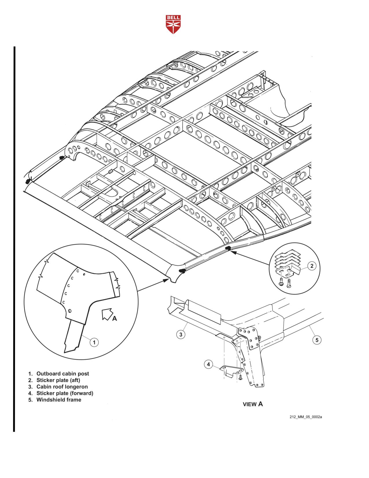
Outboard cabin post
(1, Figure 5-3), cabin roof
longeron (2), and windshield frame (5) upper corner area for
damage and cracks.
10. Striker plates (3 and 4) attachment areas for damage and
cracks.
11. Striker plates (3 and 4) for excessive wear, damage, and
corrosion.
12. Cabin floor area under crew doors for chafing and damage.
13. Crew door hinges for wear, damage, corrosion, and
security of attachment.
5-00-00
Export Classification C, ECCN EAR99
15 MAY 2020 Rev. 18
Page 101
BHT-212-MM-1
SCHEDULED INSPECTIONS
5-15.
5000 HOURS/5 YEARS INSPECTION - PART B (CONT)
INITIAL
DATA REFERENCE
INSPECTION TASK DESCRIPTION
MECH OTHER
14. Crew doors for proper fit and operation.
15. Crew seat rails for excessive wear and damage.
16. Center and outboard bulkhead, below WL 22.00 at FS
23.00, for cracks, deformation, and corrosion along structure
joints.
17. Collective and cyclic control jackshafts support intercostals
for cracks and corrosion.
18. Cyclic support for corrosion and cracks.
19. Collective, cyclic, and anti-torque control system
bellcranks, levers, and support brackets for corrosion, cracks,
and indication of wear at attaching points.
20. Crew seat support beams, at BL 14.00 and 30.00 between
FS 23.00 and 74.30, for cracks and corrosion.
21. Forward crosstube attachment points and support structure
at FS 63.33 and 74.30 for damage, corrosion, and cracks.
22. Aft crosstube attachment points and support structure at
FS 155.06 and 166.00 for damage, corrosion, and cracks.
23. Crew and passenger cabin floor, FS 23.00 to 155.06, for
corrosion and damage. Floor bonded panels for voids. Seat
fasteners and cargo tie-down rings for condition. Area around
pilot and copilot ICS foot switches for cracks.
NOTE
In the following step, removal of the fuel cells is not
required unless there is evidence of fuel leakage or
damage to the fuel cells or structure is suspected.
24. All structure under floor panels and in forward fuel cell
cavities including caps, angles, transverse bulkheads and
bonded panels between FS 74.30 and 155.06 for damage,
corrosion, cracks, and voids.
5-00-00
Page 102
Rev. 18
15 MAY 2020
Export Classification C, ECCN EAR99
BHT-212-MM-1
SCHEDULED INSPECTIONS
5-15.
5000 HOURS/5 YEARS INSPECTION - PART B (CONT)
INITIAL
DATA REFERENCE
INSPECTION TASK DESCRIPTION
MECH OTHER
NOTE
In the following step, removal of the fuel cells is not
required unless there is evidence of fuel leakage or
damage to the fuel cells or structure is suspected.
Structure that is hidden by the fuel cells only needs
to be inspected if the fuel cells are removed for some
reason or structural damage is suspected.
25. All structure under floor panels and in aft fuel cell cavities
including caps, angles, and panels between FS 155.06 and
200.00 for damage, corrosion, cracks, and voids.
26. Bottom skin, FS 23.00 to 243.937, for damage. Joints for
corrosion. Access panels and covers for condition and
attachment.
27. Main transmission compartment interior, FS 129.00 to
166.00 and WL 7.44 to 76.00, for corrosion. Bulkheads and
main beam panels for damage and corrosion. Attaching
supports and brackets for condition and security.
28. Fluid lines in transmission compartment for evidence of
leaks, condition, wear, and chafing. Clamps for condition (fluid
contamination and swelling), and security of attachment.
29. Lift beam fitting for condition and working rivets, lift link
attachment bolt hole bores for excessive wear, and bushings for
looseness.
30. Pylon (transmission) support structure for wear and cracks.
Pay particular attention to right and left horizontal supports,
forward vertical supports, and aft vertical webs.
31. Aft cabin bulkheads, FS 166.00, for damage, upper aft
flange for cracks, and bulkhead panel for damage and
disbonding.
32. Electrical/avionics compartment, FS 166.00 to 243.937,
doors for condition and security. Door frames for cracks and
corrosion. Compartment interior for condition and joints for
corrosion. Skin for damage and cracks.
5-00-00
Export Classification C, ECCN EAR99
15 MAY 2020 Rev. 18
Page 103
BHT-212-MM-1
SCHEDULED INSPECTIONS
5-15.
5000 HOURS/5 YEARS INSPECTION - PART B (CONT)
INITIAL
DATA REFERENCE
INSPECTION TASK DESCRIPTION
MECH OTHER
33. Oil cooler compartment, FS 166.00 to 243.937, doors for
condition and security. Main beam panels and bulkheads for
condition and corrosion.
34. Engine deck below the reduction gearbox, FS 211.00 to
238.00 for damage, cracks, and corrosion.
35. Firewalls, FS
155.06 to
241.22, for damage, cracks,
security of attachment, seals for condition, and seal attachment
angles for cracks.
36. Cabin roof, FS 35.00 to 166.00 above WL 68.00, BL 50.00
left and right side, for damaged skin and joints for corrosion,
bonded panels for disbonding and corrosion. Structure above
overhead console (circuit breaker panels) for cracks and
corrosion.
37. Cargo door tracks for wear, cracks, and corrosion.
38. Engine and transmission cowlings and fairings for
evidence of chafing, cracks, corrosion, and seals for condition.
39. Bulkhead, FS 241.22, for damage, corrosion, and cracks.
Tailboom attachment fittings for damage, cracks, and loose
fasteners. Tailboom attachment bolt holes for damage and
corrosion.
40. Tailboom attachment bolts for damage, wear, and
corrosion.
Chapter 53
TAILBOOM
1.
Bulkhead, BS 17.42, for corrosion and cracks. Fuselage
attachment bolt holes for damage and corrosion. Barrel nuts for
damage and corrosion.
2.
Tailboom and fin driveshaft covers for condition and
attachment.
3.
Tailboom and fin external skin for damage, corrosion, and
cracks.
4.
Tailboom access panels and covers for condition and
attachment. Tail rotor driveshaft cover hinges for wear.
5-00-00
Page 104
Rev. 18
15 MAY 2020
Export Classification C, ECCN EAR99
BHT-212-MM-1
SCHEDULED INSPECTIONS
5-15.
5000 HOURS/5 YEARS INSPECTION - PART B (CONT)
INITIAL
DATA REFERENCE
INSPECTION TASK DESCRIPTION
MECH OTHER
5.
Tailboom baggage compartment door for condition,
attachment, and door handle operation.
6.
Tailboom baggage compartment interior for damage,
panels for disbonding, and corrosion. Longerons above roof
panel for corrosion and cracks. Longerons below floor panel for
corrosion and cracks.
7.
Tailboom interior bulkheads and stringers for cracks and
corrosion.
8.
Intermediate gearbox mount pad for damage, cracks,
fretting, and corrosion.
9.
Tail rotor gearbox support fitting assembly for damage,
cracks, fretting, and corrosion. Pay particular attention to
mounting holes and lugs.
10. Tailboom exterior bonded panels adjacent to baggage
compartment for damage, delamination, and corrosion.
11. With a borescope or equivalent, inspect interior structure of
vertical fin for cracks, corrosion, fretting, and damage.
12. Control tube fairleads (grommets and guides) for wear and
security of attachment.
5-00-00
Export Classification C, ECCN EAR99
15 MAY 2020 Rev. 18
Page 104A
BHT-212-MM-1
Figure 5-3. Cabin Frame Inspection - Part B
5-00-00
Page 104B
Rev. 18
15 MAY 2020
Export Classification C, ECCN EAR99
BHT-212-MM-1
SPECIAL INSPECTIONS
5-16.
SPECIAL INSPECTION
18. Each
300 hours/12 months of transmission
operation.
Perform applicable special inspection of helicopter:
18A. Each 300 hours/12 months inspection of tail
1.
Daily inspection.
rotor control tube and bearing.
2.
Daily or each 10 hours of flight, whichever occurs
19. Each 300 hours/3 months of driveshaft operation.
first until 250 hours.
20. Main rotor grip ultrasonic inspection.
3.
Between 5 and 10 hours of flight after each
installation.
21. Each 500 hours or 6 months of blade service.
4.
Fin spar cap inspection every 8 hours.
22. Each 600 hours of transmission operation.
5.
Each 25 hours for the next four inspections.
23. Each 600 hours/12 months of tail rotor driveshaft
coupling operation.
6.
Each 25 hours of flight operation.
24. Each 600 hours/12 months of main driveshaft
7.
Each seven days in a corrosive environment and
operation.
each 30 days in a noncorrosive environment.
25. Each 1000 hours of component operation.
8.
50 hours after installation of components.
26. First 1000 hours of component time and each
9.
Each 50 hours of component operation.
3000 hours thereafter of component time.
10. Deleted.
27. Each 1000 hours/12 months of main rotor blade
operation.
11. Each
100 hour/12 calendar months of
transmission operation.
28. Each
1200 hours/24 months of component
operation.
12. Each
100 hours/12 months of intermediate
gearbox operation.
29. Deleted.
13. Each 100 hours/12 months of tail rotor gearbox
30. Each 24 months of flight control system bolt
operation.
operation.
13A. Fin spar cap inspection every 100 hours.
31. Each 3000 hours of component operation.
14. Each 100 hours/12 months of battery system
32. Each 10,000 hour total airframe time and each
operation.
300 hours/12 months of main beam cap operation.
15.
100 hours after installation of tailboom.
33.
10 years collective stick tube inspection.
16. Each 150 hours of starter generator operation.
Use the following time frame criteria when
accomplishing the required Maintenance Manual
17. Fin spar cap inspection every 300 hours.
torque checks after installation of components.
5-00-00
Export Classification C, ECCN EAR99
15 MAY 2020 Rev. 18
Page 105
BHT-212-MM-1
For additional information, refer to BHT-ALL-SPM. If
NOTE
any confusion exists, or a clarification is desired,
contact Product Support Engineering.
Torque check is the term used when the
specified torque or standard torque plus
tare torque is applied to a fastener in a
tightening direction. The specified or
Torque Check Requirements
standard torque plus tare torque would
have been previously recorded. However, if
SUGGESTED TIME
MANUAL
the specified or standard torque and tare
FRAME TO
SPECIFIES
were not recorded, use the minimum
ACCOMPLISH
specified or standard torque, plus the tare
100 hours
90 to 110 hours
torque listed in the BHT-ALL-SPM,
Chapter 2.
50 hours
40 to 60 hours
Looseness may occur until components seat
25 hours
20 to 30 hours
themselves and fasteners are tightened. This is not
cause for disassembly, however the fastener will have
10 hours
5 to 15 hours
to be torque checked again at the same scheduled
interval set for the first torque check until the assembly
is completely seated.
5-00-00
Page 106
Rev. 14
26 JUN 2013
Export Classification C, ECCN EAR99
BHT-212-MM-1
SPECIAL INSPECTIONS
5-17.
DAILY INSPECTION
INITIAL
DATA REFERENCE
INSPECTION TASK DESCRIPTION
MECH OTHER
DATE:
__________________
W.O.
_____________________
FACILITY:
_________________________________________
HELICOPTER S/N:
__________________________________
REGISTRY NO.:
____________________________________
TOTAL TIME:_______________________________________
SIGNATURE:_______________________________________
Chapter 62
MAIN ROTOR HUB GRIP 204-011-121-009
- Detailed Visual Inspection
1.
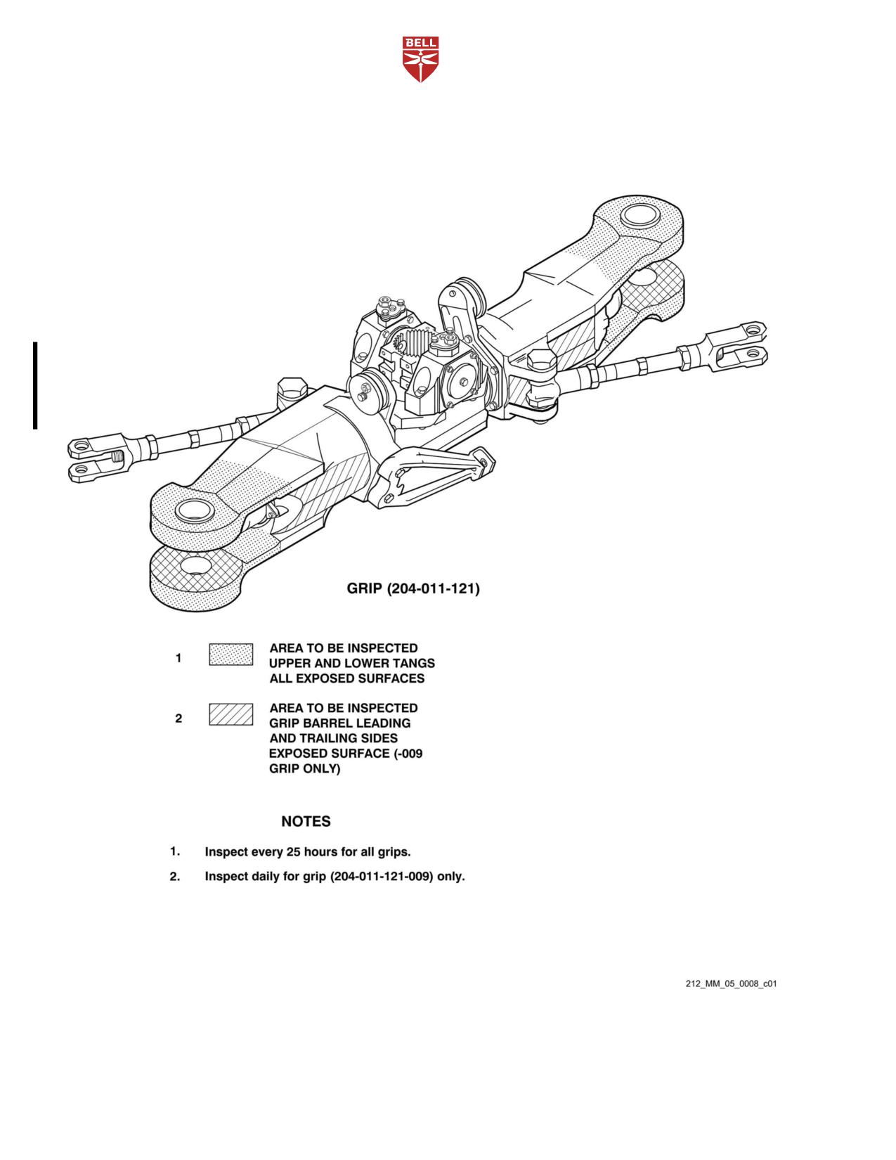
For 204-011-121-009 main rotor grip, inspect grip barrels
both leading and trailing sides for evidence of hairline cracks
(Figure 5-4).
2.
Deleted.
TAIL FIN
- Inspect
1.
Helicopters modified by TB
212-91-138
- If
TB 212-88-104 has not been incorporated, inspect right tail fin
skin for cracks.
5-00-00
Export Classification C, ECCN EAR99
15 MAY 2020 Rev. 18
Page 107
BHT-212-MM-1
Figure 5-4. Inspection of Main Rotor Hub Grip Tangs, Barrel and Drag Brace Attachment Lugs
5-00-00
Page 108
Rev. 18
15 MAY 2020
Export Classification C, ECCN EAR99
BHT-212-MM-1
SPECIAL INSPECTIONS
5-18.
DAILY OR EACH 10 HOURS OF FLIGHT OPERATION, WHICHEVER OCCURS FIRST UNTIL
250 HOURS
INITIAL
DATA REFERENCE
INSPECTION TASK DESCRIPTION
MECH OTHER
DATE:
__________________
W.O.
_____________________
FACILITY:
_________________________________________
HELICOPTER S/N:
__________________________________
REGISTRY NO.:
____________________________________
TOTAL TIME:_______________________________________
SIGNATURE:_______________________________________
NOTE
Accomplish daily or each 10 hours flight operation,
whichever occurs first until
250 hours, on
transmission with affected gears with 50 hours or
more.
Chapter 63 and
SPIRAL BEVEL GEAR 204-040-701-103
ASB 212-89-54
- Inspect
NOTE
This inspection is only applicable to transmissions/
helicopters with the spiral bevel gears, shown in
Figure 5-5, installed.
1.
Remove and inspect the transmission internal sump filter
for metal contamination. If metal contamination is evident, notify
Product Support Engineering of spiral bevel gear serial number,
hours, and type of contamination.
2.
Every 50 hours (until 250 hours), visually inspect spiral
bevel gear.
a. Remove quill pad cover (204-040-174-001) or rotor
brake quill from transmission.
5-00-00
Export Classification C, ECCN EAR99
26 JUN 2013 Rev. 14
Page 109
BHT-212-MM-1
SPECIAL INSPECTIONS
5-18.
DAILY OR EACH 10 HOURS OF FLIGHT OPERATION, WHICHEVER OCCURS FIRST UNTIL
250 HOURS (CONT)
INITIAL
DATA REFERENCE
INSPECTION TASK DESCRIPTION
MECH OTHER
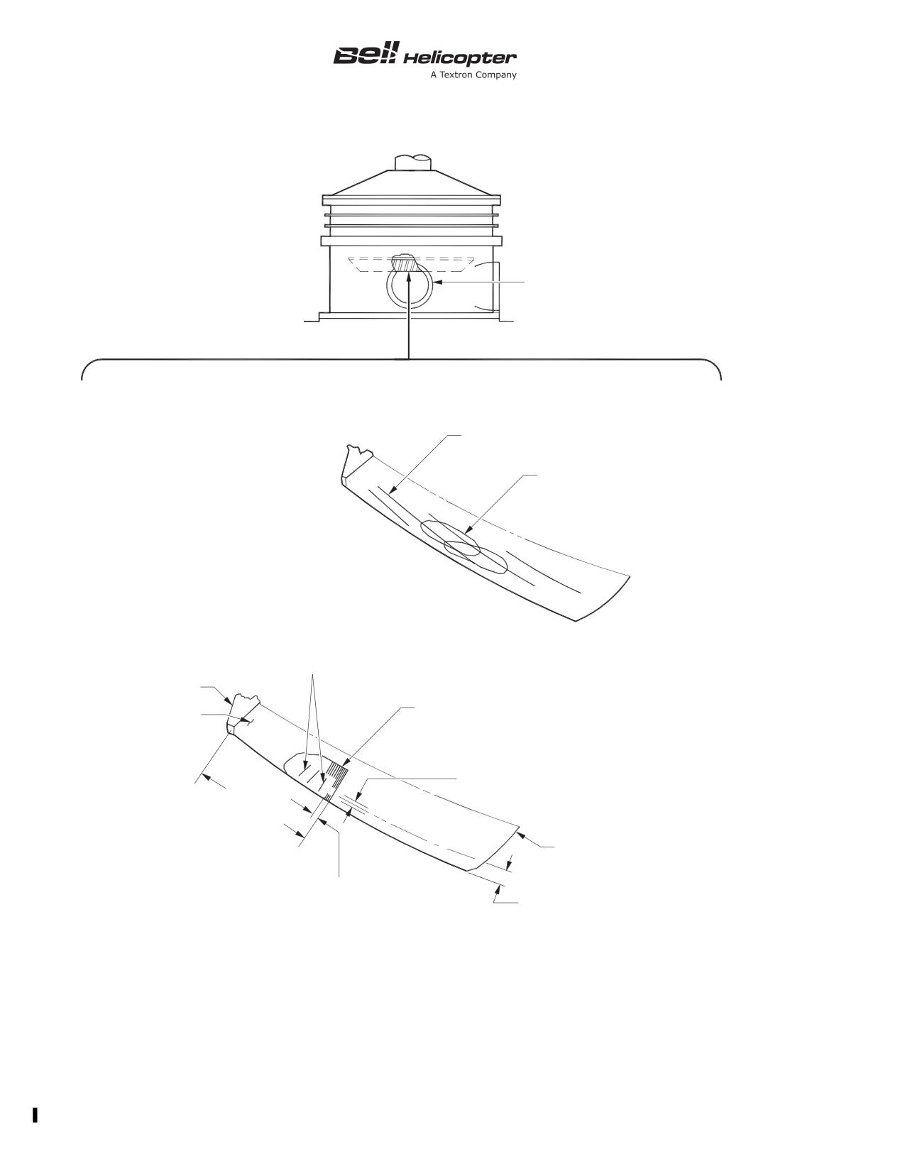
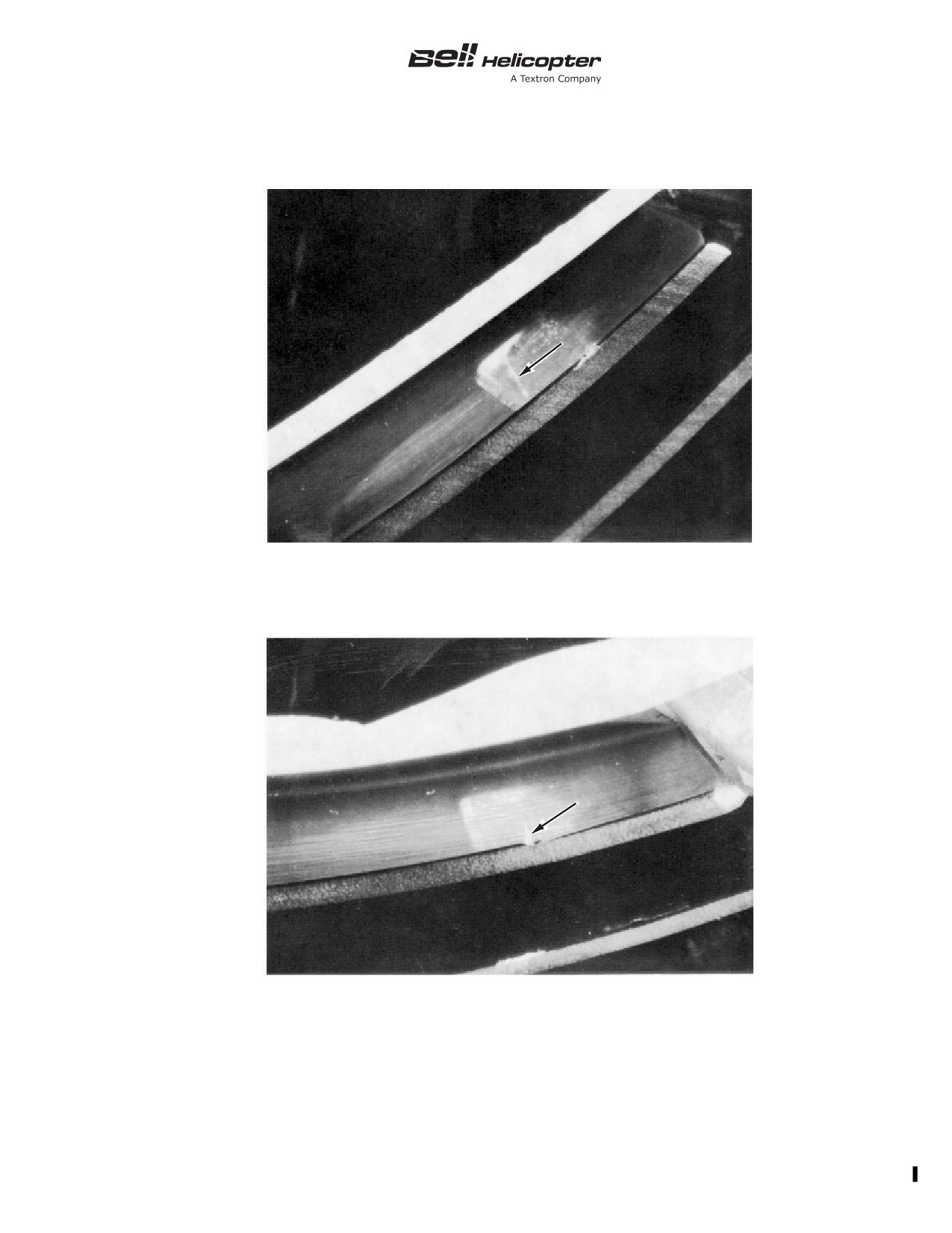
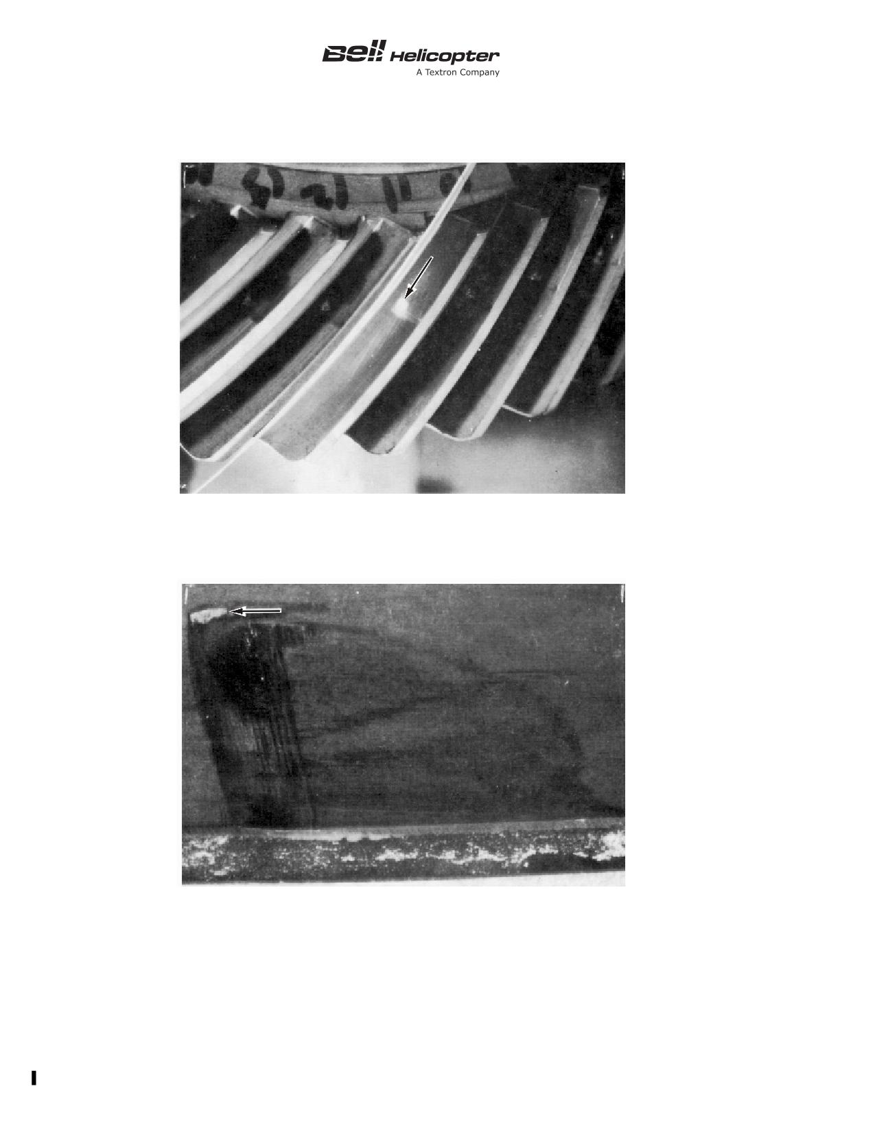
b. Utilizing port opening in main gear case and a bright
light and mirror, inspect all 62 teeth in spiral bevel gear, P/N
204-040-701-103. Carefully inspect each tooth for evidence of
chipping or loss of material (Figure 5-6).
c. Remove and replace any gear not meeting inspection
requirements set forth in step b. Notify Product Support
Engineering of serial number and total time of any gear
replaced.
d. Install quill pad cover or rotor brake quill.
3.
Spare (uninstalled) affected spiral bevel gears.
a. Return spare affected serial numbered spiral bevel
gears to Bell Helicopter Textron for inspection and
reidentification. Refer to Information Letter IL GEN-04-98 for
shipping instructions.
5-00-00
Page 110
Rev. 14
26 JUN 2013
Export Classification C, ECCN EAR99
BHT-212-MM-1
212_MM_05_0010
Figure 5-5. Spiral Bevel Gears Serial Numbers
5-00-00
Export Classification C, ECCN EAR99
26 JUN 2013 Rev. 14
Page 111
BHT-212-MM-1
ROTOR BRAKE QUILL PORT
LOOKING UP THROUGH ROTOR BRAKE QUILL PORT
MANUFACTURING FLATS
INPUT PINION COAST SIDE
PATTERN (VERY LIGHT) LOCATED
AT ONE OR TWO POSITIONS
NOT ACCEPTABLE
DETACHED STRIKE
MARKS USUALLY ONE
PER TOOTH USUALLY ON
ONE OR MORE GROUPS
OF 2, 3 OR 4 TEETH
TOE
SCORED PATCH NOT
CONCAVE SIDE
ACCEPTABLE WILL BE ON
ALL 62 TEETH
NORMAL GAP FROM GEAR ROLL NOT
0.70 IN.
ACCEPTABLE IF GAP IS NOT EVIDENT
(17.78 mm)
APPROX.
HEEL
0.01 TO 0.04 IN.
(0.254 TO 1.016 mm)
0.050 IN. (1.270 mm)
ACCEPTABLE BAND
APPROX. PITCH DIA.
OF BRIGHT MARKING ON
ALL 62 TEETH
212_MM_05_0004
Figure 5-6. Inspection of Spiral Bevel Gear (Sheet 1 of 3)
5-00-00
Page 112
Rev. 14
26 JUN 2013
Export Classification C, ECCN EAR99
BHT-212-MM-1
REGISTRATION NO.__________________________
SPIRAL BEVEL GEAR (204-040-701) UNACCEPTABLE PATTERN
SPIRAL BEVEL GEAR (204-040-7
01) UNACCEPTABLE PATTERN
212_MM_05_0005
Figure 5-6. Inspection of Spiral Bevel Gear (Sheet 2 of 3)
5-00-00
Export Classification C, ECCN EAR99
26 JUN 2013 Rev. 14
Page 113
BHT-212-MM-1
REGISTRATION NO.__________________________
SPIRAL BEVEL GEAR (204-040-701) UNACCEPTABLE PATTERN
SPIRAL BEVEL GEAR (204-040-701) UNACCEPTABLE PATTERN
212_MM_05_0006
Figure 5-6. Inspection of Spiral Bevel Gear (Sheet 3 of 3)
5-00-00
Page 114
Rev. 14
26 JUN 2013
Export Classification C, ECCN EAR99
BHT-212-MM-1
SPECIAL INSPECTIONS
5-19.
BETWEEN 5 AND 10 HOURS OF FLIGHT AFTER EACH INSTALLATION
INITIAL
DATA REFERENCE
INSPECTION TASK DESCRIPTION
MECH OTHER
DATE:
__________________
W.O.
_____________________
FACILITY:
_________________________________________
HELICOPTER S/N:
__________________________________
REGISTRY NO.:
____________________________________
TOTAL TIME:_______________________________________
SIGNATURE:_______________________________________
NOTE
Accomplish between 5 and 10 hours of flight after
each installation.
Chapter 62
MAIN ROTOR
1.
Torque check main rotor retaining nut
520 to
780 foot-pounds (705 to 1057 Nm).
Chapter 64
2.
Main rotor hub blade attachment bolts, torque check nuts
260 to 300 foot-pounds (353 to 407 Nm).
TAIL ROTOR HUB AND BLADE ASSEMBLY
1.
Torque check tail rotor retaining nut 900 inch-pounds
(101.69 Nm).
Chapter 65
TAIL ROTOR GEARBOX
Torque check tail rotor gearbox retaining nuts
200 to
235 inch-pounds (22.60 to 26.55 Nm). Using a 0.005 inch
(0.127 mm) or less feeler gauge, verify no gap exists between
gearbox input quill shim and gearbox case shim.
5-00-00
Export Classification C, ECCN EAR99
15 JUL 2021 Rev. 19
Page 115
BHT-212-MM-1
SPECIAL INSPECTIONS
5-19.
BETWEEN 5 AND 10 HOURS OF FLIGHT AFTER EACH INSTALLATION (CONT)
INITIAL
DATA REFERENCE
INSPECTION TASK DESCRIPTION
MECH OTHER
Chapter 65
INTERMEDIATE GEARBOX
Torque check intermediate gearbox retaining bolts
50 to
70 inch-pounds (5.65 to 7.91 Nm).
5-00-00
Page 116
Rev. 14
26 JUN 2013
Export Classification C, ECCN EAR99
BHT-212-MM-1
SPECIAL INSPECTIONS
5-20.
FIN SPAR CAP INSPECTION EVERY 8 HOURS
INITIAL
DATA REFERENCE
INSPECTION TASK DESCRIPTION
MECH OTHER
DATE:
__________________
W.O.
_____________________
FACILITY:
_________________________________________
HELICOPTER S/N:
__________________________________
REGISTRY NO.:
____________________________________
TOTAL TIME:_______________________________________
SIGNATURE:_______________________________________
1.
Accomplish inspection of fin spar caps P/N
212-030-125-001,
212-030-447-001 and
212-030-447-101
every 8 flight hours.
2.
This special inspection is not required if fin spar cap P/N
212-030-447-117 has been installed as original equipment or in
accordance with TB 212-00-184.
3.
Fin spar cap P/N 212-030-447-117 can be identified by the
presence of decals that identify the cold-worked holes.
FIN SPAR CAP 212-030-125-001 AND 212-030-447-001/101
ASB 212-00-110
1.
Carry out 8 hour recurring inspection in accordance with
applicable section of ASB 212-00-110.
2.
Any discrepancies (cracks, corrosion, debonding, or other
damage) are to be reported to Product Support Engineering
before further flight.
5-00-00
Export Classification C, ECCN EAR99
26 JUN 2013 Rev. 14
Page 117/118
BHT-212-MM-1
SPECIAL INSPECTIONS
5-21.
EACH 25 HOURS FOR THE NEXT FOUR INSPECTIONS
INITIAL
DATA REFERENCE
INSPECTION TASK DESCRIPTION
MECH OTHER
DATE:
__________________
W.O.
_____________________
FACILITY:
_________________________________________
HELICOPTER S/N:
__________________________________
REGISTRY NO.:
____________________________________
TOTAL TIME:_______________________________________
SIGNATURE:_______________________________________
TAIL ROTOR HANGER BEARINGS WITNESS MARKS
NOTE
Accomplish visual inspection of witness marks (only
applicable to hanger bearings 204-040-623-003 and
-005) each
25 flight hours for the next four
inspections after installation or initial inspection of
hanger bearings.
NOTE
All newly installed hanger bearings must contain a
scribe or paint witness mark and will require an initial
inspection.
ASB 212-95-95
1.
Perform helicopter run-up for
5 minutes. Shut down
Revision C
helicopter and inspect tail rotor hanger bearings for movement
of the dust shields, identified by breakage of the witness marks.
Remove any bearings from service that display dust shield
movement.
2.
Hanger bearings not displaying movement at the run-up
may remain in service, but must be inspected for dust shield
movement at each of the next four mandatory
25 hour
inspections, or any time the bearing is inspected between any of
the 25 hour inspections. Bearings that do not display grease
shield movement after the fourth 25 hour inspection may remain
in service with no further inspection required. Record
accomplishment of inspection in the helicopter log book.
5-00-00
Export Classification C, ECCN EAR99
26 JUN 2013 Rev. 14
Page 119
BHT-212-MM-1
SPECIAL INSPECTIONS
5-21.
EACH 25 HOURS FOR THE NEXT FOUR INSPECTIONS (CONT)
INITIAL
DATA REFERENCE
INSPECTION TASK DESCRIPTION
MECH OTHER
3.
Remove any hanger bearing from service where the
witness marks indicate that the grease shield has moved.
5-00-00
Page 120
Rev. 14
26 JUN 2013
Export Classification C, ECCN EAR99
BHT-212-MM-1
SPECIAL INSPECTIONS
5-22.
EACH 25 HOURS OF FLIGHT OPERATION
INITIAL
DATA REFERENCE
INSPECTION TASK DESCRIPTION
MECH OTHER
DATE:
__________________
W.O.
_____________________
FACILITY:
_________________________________________
HELICOPTER S/N:
__________________________________
REGISTRY NO.:
____________________________________
TOTAL TIME:_______________________________________
SIGNATURE:_______________________________________
NOTE
Accomplish each 25 flight hours of operation.
Chapter 62
SWASHPLATE GIMBAL RING BOLTS
NOTE
This swashplate gimbal ring bolt special inspection is
applicable to helicopters on Part A scheduled
inspection program only. The intent of this special
inspection is included in the
25 hour/30 day
inspection - Part B.
Do not attempt to turn bolts or nuts. Bolt rotation will
fail loctite in joint and permit bolt wear.
The presence of black oxide powder will require
investigation to determine the cause.
- Inspect
1.
Grasp swashplate rotating ring, 204-011-403, and attempt
to move it in a horizontal plane on an axis in line with gimbal ring
attach points to support assembly, 204-011-404. Maximum
allowable axial looseness across gimbal ring bearings and
attaching bolts is 0.005 inch (0.127 mm).
5-00-00
Export Classification C, ECCN EAR99
26 JUN 2013 Rev. 14
Page 121
BHT-212-MM-1
SPECIAL INSPECTIONS
5-22.
EACH 25 HOURS OF FLIGHT OPERATION (CONT)
INITIAL
DATA REFERENCE
INSPECTION TASK DESCRIPTION
MECH OTHER
2.
Repeat step 1 on axis 90° and attempt to detect looseness
in line with gimbal ring attach points to inner ring. Maximum
allowable axial looseness across the gimbal ring bearing and
attaching bolts is 0.005 inch (0.127 mm).
Chapter 62
204-011-451 TRUNNION INSTALLED IN 204-011-403
SWASHPLATE ROTATING RING
- Detailed Visual Inspection
1.
Check trunnions for excessive axial looseness.
MAIN ROTOR HUB GRIP 204-011-121
- Detailed Visual Inspection
1.
Prepare both main rotor grip tangs for inspection by
cleaning exposed surfaces with denatured alcohol (C-326) as
per the BHT-ALL-SPM. Wipe dry.
2.
Inspect grip surfaces for evidence of hairline cracks on grip
barrels and upper and lower tangs exposed surfaces. Pay
particular attention to the lower tang lower surface from blade
bolt bushing flange to the trailing and leading edge of the tang
(Figure 5-4).
Chapter 62
MAIN ROTOR BLADE
ASB 212-08-130
1.
Wash upper and lower main rotor blade surfaces with a
solution of cleaning compound (C-318) and water. Rinse
thoroughly and wipe dry.
NOTE
Accomplishment of this inspection does not require
removal of the blades from the main rotor hub.
5-00-00
Page 122
Rev. 16
15 NOV 2018
Export Classification C, ECCN EAR99
BHT-212-MM-1
SPECIAL INSPECTIONS
5-22.
EACH 25 HOURS OF FLIGHT OPERATION (CONT)
INITIAL
DATA REFERENCE
INSPECTION TASK DESCRIPTION
MECH OTHER
CAUTION
FOR INSPECTION OF THE BLADE ON THE
LOWER SIDE, THE BLADE MUST BE
SUPPORTED AT THE TIP TO REMOVE ANY BOW.
FAILURE TO SUPPORT THE BLADE
ADEQUATELY MAY RENDER CHORDWISE
CRACKS DIFFICULT TO DETECT.
2.
Inspect the main rotor blade upper and lower grip plates
and doublers for their entire length and chord width. Inspect for
signs of cracks, corrosion, and edge voids, paying particular
attention to the bond lines between doublers, grip plates, and
skin. Hair line cracks in the paint finish should be suspect for
possible cracks/voids.
3.
Wipe the area between blade stations 24.5 and 85.0 with a
clean cloth (C-516) soaked with isopropyl alcohol (C-385). Wipe
dry with a clean cloth (C-516).
NOTE
Accomplish step 4 immediately after carrying out the
above alcohol wipe. Any potential cracks in the bond
lines between doublers or grip plates will be
indicated by the presence of excess alcohol bleeding
out of an edge void. The excess alcohol in the void
will appear as a dark line between the bond lines of
the doublers.
NOTE
When inspecting the blade for cracks, the strong light
source should be applied at an oblique angle and
perpendicular to the crack orientation we attempt to
detect. For example, for a chordwise crack, the light
source should be applied in a spanwise direction.
CAUTION
DO NOT TO REMOVE ANY PARENT MATERIAL
FROM THE SKIN/DOUBLERS DURING SANDING
OPERATION.
5-00-00
Export Classification C, ECCN EAR99
15 MAY 2020 Rev. 18
Page 123
BHT-212-MM-1
SPECIAL INSPECTIONS
5-22.
EACH 25 HOURS OF FLIGHT OPERATION (CONT)
INITIAL
DATA REFERENCE
INSPECTION TASK DESCRIPTION
MECH OTHER
4.
Carry out a detailed visual inspection of the top and bottom
of the blade between blade stations 24.5 and 85.0 using a
3X magnifying glass and a strong light source. Check for
evidence of a dark line between doublers, grip plates, and skin
with excess alcohol bleeding out of possible edge voids. Any
cracks in the finish must be investigated further by removing
paint in affected areas (sand with 180-220 grit abrasive paper
(C-423) in a spanwise direction) to determine if the grip plate/
doublers are cracked or voided. Any crack in paint finish that
follows grip plate/doubler outline may indicate a possible edge
void.
5.
Carry out a detailed visual inspection of the top and bottom
of the blade between blade stations 26.0 and 30.0 in the blade
bolt area with a 10X power magnifying glass and a strong light
source. Inspect the leading edge and trailing edge sides of the
blade at the blade bolt span station for evidence of cracks or
dark lines in the grip plates going across the doublers. Any
cracks in the finish must be investigated further by removing
paint in the affected areas. Sand the affected area in a
spanwise direction with an abrasive cloth or paper (C-406) 180
to 220 grit to determine if the grip plate/doublers are cracked or
voided.
6.
If cracks in grip plate/doublers are found, immediately
remove the main rotor blade from service and contact Product
Support Engineering. If no cracks are detected, continue with
step 7.
CAUTION
DO NOT TO REMOVE ANY PARENT MATERIAL
FROM THE SKIN/DOUBLERS DURING SANDING
OPERATION.
7.
If edge voids between grip plate/doublers/skin are found,
determine depth and length by using 0.0015 inch (0.038 mm)
feeler gauge. If edge voids are near outboard tip of grip plate /
doublers, also carefully tap inspect suspect area. Refer to
BHT-212-CR&O, Chapter
62 for void repair limits and
inspection/repair instructions. If no voids are detected, continue
with step 8.
5-00-00
Page 124
Rev. 18
15 MAY 2020
Export Classification C, ECCN EAR99
BHT-212-MM-1
SPECIAL INSPECTIONS
5-22.
EACH 25 HOURS OF FLIGHT OPERATION (CONT)
INITIAL
DATA REFERENCE
INSPECTION TASK DESCRIPTION
MECH OTHER
8.
Refinish the sanded area as per BHT-212-MM-6,
Chapter 62.
9.
Following the inspection, apply a light coat of preservative
oil (C-125) to all surfaces of blade.
TRANSMISSION MAIN CASE 204-040-353
1.
Inspect main case web above the input quill at the
12 o’clock position that has been previously reworked per the
BHT-212-CR&O-3 by doing the following:
a. Visually inspect for signs of oil leakage in case wall. If
noted, remove assembly and do an NDI on the case assembly.
b. If no leakage is noted, thoroughly clean the area with
alcohol/naphtha and visually inspect with minimum
3X magnifying glass for signs of cracks.
c. Any crack is cause for immediate replacement of main
case.
Chapter 64
TAIL ROTOR HUB ASSEMBLY
- Detailed Visual Inspection
1.
Flapping bearings 212-010-723-001 or 212-010-768-001
exposed outer races for cracks using a 3X magnifying glass.
Any crack is cause for immediate replacement of both bearings.
2.
Inspect tail rotor yoke
212-010-704,
212-010-744, or
212-011-702.
TAIL ROTOR STATIC STOP
ASB 212-96-100 and
1.
Inspect flapping stop 212-010-738 or 212-011-713 for
ASB 212-96-101
yielding as noted in Chapter 64, to determine if tail rotor yoke
assembly may have been exposed to bending.
If any doubt exists as to the serviceability of these components,
contact Product Support Engineering.
5-00-00
Export Classification C, ECCN EAR99
15 MAY 2020 Rev. 18
Page 125
BHT-212-MM-1
SPECIAL INSPECTIONS
5-22.
EACH 25 HOURS OF FLIGHT OPERATION (CONT)
INITIAL
DATA REFERENCE
INSPECTION TASK DESCRIPTION
MECH OTHER
Chapter 64
TAIL ROTOR BLADE
1.
Clean each tail rotor blade by hand using mild soap and
cheesecloth (C-486) in a spanwise direction; dry thoroughly.
2.
Carry out a detailed visual inspection of both sides of the
entire blade with a 3X magnifying glass, or higher, and a bright
light. Inspect the tail rotor blade skin, leading edge spar,
doublers, grip plates, and trailing edge for cracks, corrosion,
nicks, dents, and scratches. Refer to Chapter 64 for damage
limits.
3.
If any blistering, peeling, flaking, bubbling, or cracked paint
is detected, remove the paint from the affected area and visually
inspect the affected area for corrosion or a crack using a 10X
magnifying glass, or higher. If any corrosion is found, measure
the depth of the corrosion.
4.
Only superficial corrosion that can be removed with
aluminum wool or very fine grade abrasive pad (C-407) is
permissible. Corrosion on the spar 0.003 inch (0.076 mm) deep
or less is acceptable when polished out. Replace any blade that
has corrosion on the spar greater than 0.003 inch (0.076 mm).
5.
If a nick, scratch, or dent is found, visually inspect for crack
using a 10X magnifying glass, or higher, and measure the depth
of the damage. (A digital optical micrometer is one tool that can
be used for this measurement).
6.
Repair damage and/or corrosion found on tail rotor blades
in accordance with Chapter 64.
7.
Replace any blade that has a crack. No cracks are
permitted.
NOTE
Removal of the tail rotor blades is not required for the
following inspection.
ASB 212-13-147
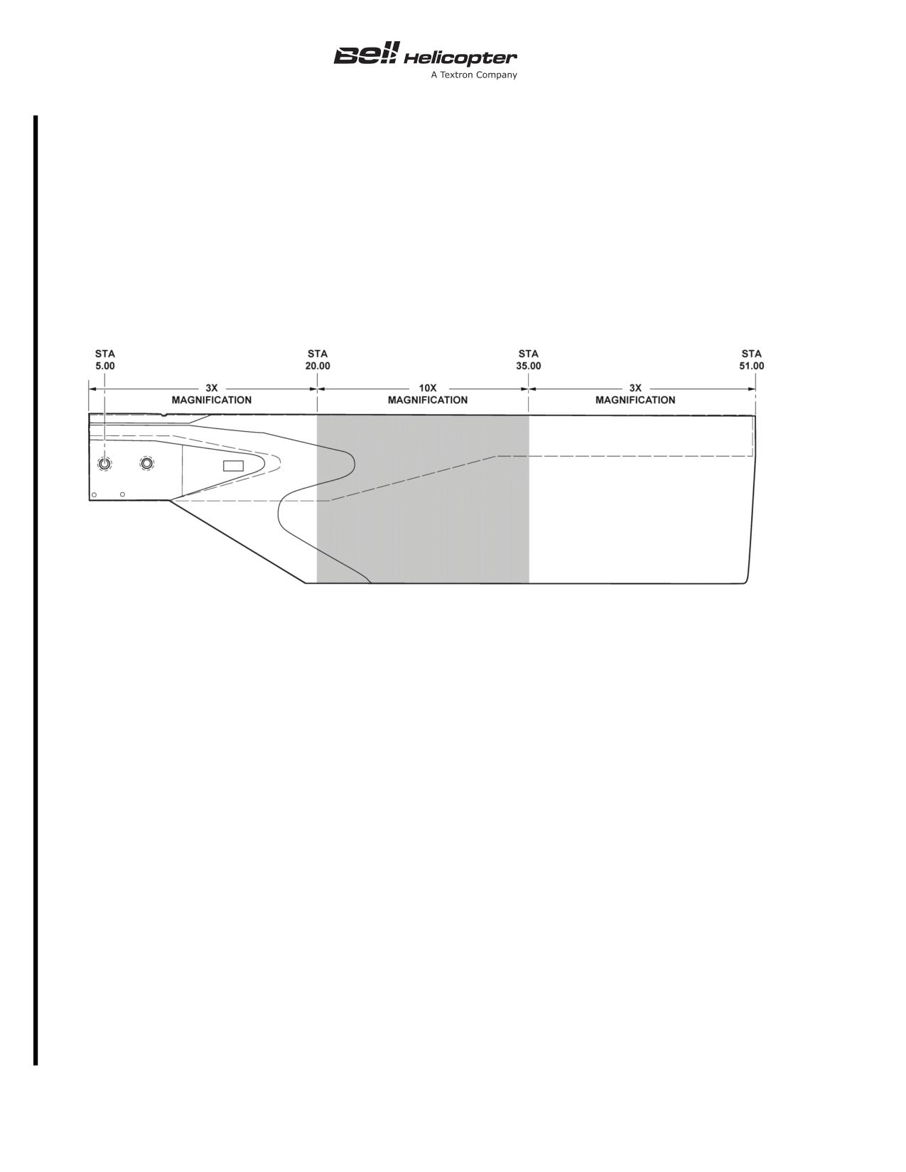
8.
Carry out a further detailed inspection of both sides of the
blade between stations 20.00 to 35.00 (Figure 5-6A), with a 10X
magnifying glass and a bright light.
5-00-00
Page 126
Rev. 18
15 MAY 2020
Export Classification C, ECCN EAR99
BHT-212-MM-1
SPECIAL INSPECTIONS
5-22.
EACH 25 HOURS OF FLIGHT OPERATION (CONT)
INITIAL
DATA REFERENCE
INSPECTION TASK DESCRIPTION
MECH OTHER
9.
If any blistering, peeling, flaking, bubbling, or cracked paint
is detected, remove the paint from the affected area by sanding
in a spanwise direction only with an abrasive cloth or paper
(C-406) 240 grit or finer and a final sanding using an abrasive
cloth or paper (C-406) 400-grit or finer. After paint removal,
visually inspect the affected area for damage using a 10X
magnifying glass. Damage beyond the limits given in Chapter
64 requires blade removal from service.
10. Only superficial corrosion that can be removed with
aluminum wool or very fine grade abrasive pad (C-407) is
permissible. Corrosion on the spar 0.003 inch deep or less is
acceptable when polished out. Replace any blade that has
corrosion on the spar greater than 0.003 inch.
11. If a nick, scratch, or dent is found, visually inspect for crack
using a 10X magnifying glass, or higher, and measure the depth
of the damage. (A digital optical micrometer is one tool that can
be used for this measurement).
12. Repair damage and/or corrosion found on tail rotor blades
in accordance with Chapter 64.
13. Replace any blade that has a crack. No cracks are
permitted.
14. If paint was removed during the above steps, carry out
paint touch up/refinishing in accordance with Chapter 64.
5-00-00
Export Classification C, ECCN EAR99
15 NOV 2018 Rev. 16
Page 126A
BHT-212-MM-1
212_MM_05_0006a
Figure 5-6A. Tail Rotor Blade - Detailed Inspection
5-00-00
Page 126B
Rev. 16
15 NOV 2018
Export Classification C, ECCN EAR99
BHT-212-MM-1
SPECIAL INSPECTIONS
5-23.
EACH SEVEN DAYS IN A CORROSIVE ENVIRONMENT AND EACH 30 DAYS IN A
NONCORROSIVE ENVIRONMENT
INITIAL
DATA REFERENCE
INSPECTION TASK DESCRIPTION
MECH OTHER
DATE:
__________________
W.O.
_____________________
FACILITY:
_________________________________________
HELICOPTER S/N:
__________________________________
REGISTRY NO.:
____________________________________
TOTAL TIME:_______________________________________
SIGNATURE:_______________________________________
NOTE
Accomplish each seven days in a corrosive
environment and each 30 days in a noncorrosive
environment.
Chapter 62
MAIN ROTOR BLADES 204-012-001 AND 212-015-501
- Clean
1.
Wash upper and lower surfaces with a solution of cleaning
compound (C-318) and water. Rinse thoroughly and wipe dry.
2.
Inspect surfaces for condition.
3.
Apply a light coat of preservative oil (C-125) to surfaces of
blade, including areas between main rotor hub grip tangs.
5-00-00
Export Classification C, ECCN EAR99
15 MAY 2020 Rev. 18
Page 127/128
BHT-212-MM-1
SPECIAL INSPECTIONS
5-24.
50 HOURS AFTER INSTALLATION OF COMPONENTS
INITIAL
DATA REFERENCE
INSPECTION TASK DESCRIPTION
MECH OTHER
DATE:
__________________
W.O.
_____________________
FACILITY:
_________________________________________
HELICOPTER S/N:
__________________________________
REGISTRY NO.:
____________________________________
TOTAL TIME:_______________________________________
SIGNATURE:_______________________________________
NOTE
Accomplish
50 flight hours after installation of
components.
Chapter 53
TAILBOOM
Torque check anti-torque bellcrank support 212-001-706-001/
101 attachment nuts 75 to 95 inch-pounds (8.47 to 10.73 Nm).
Chapter 63
ROTOR BRAKE
1.
Torque check brake assembly (caliper) attachment bolts 80
to 100 inch-pounds (9.04 to 11.30 Nm).
2.
Torque check brake disc attachment bolts
50 to
70 inch-pounds (5.65 to 7.91 Nm).
5-00-00
Export Classification C, ECCN EAR99
26 JUN 2013 Rev. 14
Page 129/130
BHT-212-MM-1
SPECIAL INSPECTIONS
5-25.
EACH 50 HOURS OF COMPONENT OPERATION
INITIAL
DATA REFERENCE
INSPECTION TASK DESCRIPTION
MECH OTHER
DATE:
__________________
W.O.
_____________________
FACILITY:
_________________________________________
HELICOPTER S/N:
__________________________________
REGISTRY NO.:
____________________________________
TOTAL TIME:_______________________________________
SIGNATURE:_______________________________________
NOTE
Accomplish each 50 hours of component operation.
Chapter 63
TRANSMISSION
- Detailed Visual Inspection
1.
Transmission 212-040-001-115, -119, -123, and -127 -
remove internal filter and sump chip detector. Visually inspect
filter element and detector for metallic chips, particles, and
contamination. If contamination or debris is found, investigate to
determine cause. Thoroughly clean and reinstall detector and
filter. Service transmission oil system (Chapter 12) to proper
level.
NOTE
Accomplish each 50 hours of component operation.
Chapter 65
TAIL ROTOR PITCH CHANGE SHAFT (CROSSHEAD)
BEARING 212-010-762-001
- Inspect
NOTE
The following inspection does not apply to helicopter
S/N 30712 and subsequent or to helicopter S/N
30711 and prior, after modification by SI 212-49.
5-00-00
Export Classification C, ECCN EAR99
26 JUN 2013 Rev. 14
Page 131
BHT-212-MM-1
SPECIAL INSPECTIONS
5-25.
EACH 50 HOURS OF COMPONENT OPERATION (CONT)
INITIAL
DATA REFERENCE
INSPECTION TASK DESCRIPTION
MECH OTHER
1.
Visually inspect bearing for indications of lubricant
depletion, metal contamination, and bearing for roughness
when rotated by hand. Rough bearing or metal contamination is
cause for immediate replacement.
HELICOPTERS MODIFIED BY TB 212-91-138
TB 212-76-18
If Technical Bulletins 212-76-18, 212-86-92 and 212-91-132
TB 212-86-92
have not been incorporated, the following listed inspection is
TB 212-91-132
mandatory.
1.
Inspect lift beam caps for cracks.
2.
Inspect L/H spar cap, fin for cracks.
3.
Inspect lift link fitting for cracks.
5-00-00
Page 132
Rev. 14
26 JUN 2013
Export Classification C, ECCN EAR99
BHT-212-MM-1
SPECIAL INSPECTIONS
5-26.
EACH 100 HOURS OF MAIN ROTOR BLADE OPERATION - DELETED
INITIAL
DATA REFERENCE
INSPECTION TASK DESCRIPTION
MECH OTHER
NOTE
The Each 100 Hours of Main Rotor Blade Operation
special inspection has been moved to the Each 25
Hours of Flight Operation special inspection.
5-00-00
Export Classification C, ECCN EAR99
26 JUN 2013 Rev. 14
Page 133/134
BHT-212-MM-1
SPECIAL INSPECTIONS
5-27.
EACH 100 HOURS/12 MONTHS OF TRANSMISSION OPERATION
INITIAL
DATA REFERENCE
INSPECTION TASK DESCRIPTION
MECH OTHER
DATE:
__________________
W.O.
_____________________
FACILITY:
_________________________________________
HELICOPTER S/N:
__________________________________
REGISTRY NO.:
____________________________________
TOTAL TIME:_______________________________________
SIGNATURE:_______________________________________
NOTE
Accomplish each
100 hours or
12 months of
transmission operation, whichever occurs first.
Chapter 63
TRANSMISSION
- General Visual Inspection
NOTE
Step 1 applicable to helicopters S/N 30501 to 31206
with 10-micron external oil filter elements installed
(PRE-TB 212-83-78).
1.
Helicopters with 10-micron external oil filters installed
accomplish the following:
a. Drain transmission oil system.
b. Replace external oil filter element.
c. Remove sump screen and inspect for debris.
d. If debris is found, determine and correct cause.
e. Thoroughly clean and reinstall sump screen.
f. Service transmission to proper level (Chapter 12).
5-00-00
Export Classification C, ECCN EAR99
15 MAY 2020 Rev. 18
Page 135
BHT-212-MM-1
SPECIAL INSPECTIONS
5-27.
EACH 100 HOURS/12 MONTHS OF TRANSMISSION OPERATION (CONT)
INITIAL
DATA REFERENCE
INSPECTION TASK DESCRIPTION
MECH OTHER
CAUTION
DO NOT SUBSTITUTE 10 MICRON FOR
3 MICRON FILTER ELEMENT FOR HELICOPTERS
S/N
31207 AND SUBSEQUENT (AND
HELICOPTERS MODIFIED BY TB 212-83-78).
NOTE
Step 2 applicable to helicopters S/N 31207 and
subsequent (and helicopters modified by
TB 212-83-78) which use 3-micron external oil filter
element. The oil change, external filter replacement,
sump screen removal and inspection for debris are
extended to
1/2 transmission TBO interval or
12 months, whichever occurs first.
2.
Helicopters with
3-micron external oil filters installed
accomplish the following:
a. Drain transmission oil system.
b. Replace external oil filter element.
c. Remove sump screen and inspect for debris.
d. If debris is found, determine and correct cause.
e. Thoroughly clean and reinstall sump screen.
f. Service transmission to proper level (Chapter 12).
3.
Deleted.
4.
Visually inspect the main case,
204-040-353-023, for
cracks in web above input quill bore (using dye penetrant
method if case has been previously reworked). Any crack
indication is cause for replacement of case.
5-00-00
Page 136
Rev. 18
15 MAY 2020
Export Classification C, ECCN EAR99
BHT-212-MM-1
SPECIAL INSPECTIONS
5-28.
EACH 100 HOURS/12 MONTHS OF INTERMEDIATE GEARBOX OPERATION
INITIAL
DATA REFERENCE
INSPECTION TASK DESCRIPTION
MECH OTHER
DATE:
__________________
W.O.
_____________________
FACILITY:
_________________________________________
HELICOPTER S/N:
__________________________________
REGISTRY NO.:
____________________________________
TOTAL TIME:_______________________________________
SIGNATURE:_______________________________________
NOTE
Accomplish each 100 hours or 12 months inspection
of intermediate gearbox operation, whichever occurs
first.
INTERMEDIATE GEARBOX
1.
Deleted
2.
Deleted
Chapter 12
3.
Change oil in 212-040-003-007.
NOTE
Oil change interval for gearbox 212-040-003-023 is
every 300 hours or 12 months, whichever occurs
first.
5-00-00
Export Classification C, ECCN EAR99
15 JUL 2021 Rev. 19
Page 137/138
BHT-212-MM-1
SPECIAL INSPECTIONS
5-29.
EACH 100 HOURS/12 MONTHS OF TAIL ROTOR GEARBOX OPERATION
INITIAL
DATA REFERENCE
INSPECTION TASK DESCRIPTION
MECH OTHER
DATE:
__________________
W.O.
_____________________
FACILITY:
_________________________________________
HELICOPTER S/N:
__________________________________
REGISTRY NO.:
____________________________________
TOTAL TIME:_______________________________________
SIGNATURE:_______________________________________
NOTE
Accomplish each 100 hours or 12 months inspection
of tail rotor gearbox operation, whichever occurs first.
TAIL ROTOR GEARBOX
1.
Deleted
2.
Deleted
Chapter 12
3.
Change oil in gearbox 212-040-004-005.
NOTE
Oil change interval for gearbox 212-040-004-009 is
every 300 hours or 12 months, whichever occurs
first.
5-00-00
Export Classification C, ECCN EAR99
15 JUL 2021 Rev. 19
Page 139/140
BHT-212-MM-1
SPECIAL INSPECTIONS
5-29A. FIN SPAR CAP INSPECTION EVERY 100 HOURS
INITIAL
DATA REFERENCE
INSPECTION TASK DESCRIPTION
MECH OTHER
DATE:
__________________
W.O.
_____________________
FACILITY:
_________________________________________
HELICOPTER S/N:
__________________________________
REGISTRY NO.:
____________________________________
TOTAL TIME:_______________________________________
SIGNATURE:_______________________________________
NOTE
Accomplish inspection of fin spar cap P/N
212-030-447-117 every 100 flight hours.
This special inspection is applicable only if fin spar
cap P/N 212-030-447-117 has been installed as
original equipment or in accordance with
TB 212-00-184.
ASB 212-20-162
FIN SPAR CAP 212-030-447-117
Chapter 53
1.
Remove the vertical fin driveshaft cover and 42° gearbox
Chapter 65
cover to gain access to the spar cap angle.
2.
Clean exposed area of spar cap.
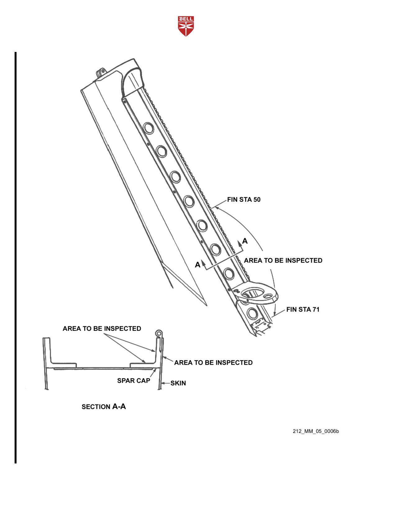
3.
Inspect both flanges of the spar cap between fin station
50.00 and 71.00 for cracks, loose rivets and other damages
using a 10X magnifying glass and a bright light (Figure 5-6B).
4.
Inspect the exterior area of fin skin P/N 212-030-099-105 in
contact with the spar cap for cracks, loose rivets and/or
distortion.
5.
If no damage is found, reinstall the 42° gearbox cover and
vertical fin driveshaft cover.
6.
Any discrepancies (cracks, debonding, or other damage) is
found, report to Product Support Engineering before further
flight.
5-00-00
Export Classification C, ECCN EAR99
15 MAY 2020 Rev. 18
Page 140A
BHT-212-MM-1
Figure 5-6B. Spar Cap Inspection
5-00-00
Page 140B
Rev. 18
15 MAY 2020
Export Classification C, ECCN EAR99
BHT-212-MM-1
SPECIAL INSPECTIONS
5-30.
EACH 100 HOURS/12 MONTHS OF BATTERY SYSTEM OPERATION
INITIAL
DATA REFERENCE
INSPECTION TASK DESCRIPTION
MECH OTHER
DATE:
__________________
W.O.
_____________________
FACILITY:
_________________________________________
HELICOPTER S/N:
__________________________________
REGISTRY NO.:
____________________________________
TOTAL TIME:_______________________________________
SIGNATURE:_______________________________________
NOTE
Accomplish each 100 hours or 12 months inspection
of battery system operation, whichever occurs first.
BATTERY SYSTEM
- Detailed Visual Inspection
Chapter 96 and
1.
Service battery in accordance with the battery
BHT-ALL-SPM
manufacturer’s recommendations.
- Operational Check
1.
Operationally check battery temperature sensor caution
light system.
5-00-00
Export Classification C, ECCN EAR99
26 JUN 2013 Rev. 14
Page 141/142
BHT-212-MM-1
SPECIAL INSPECTIONS
5-31.
100 HOURS AFTER INSTALLATION OF TAILBOOM
INITIAL
DATA REFERENCE
INSPECTION TASK DESCRIPTION
MECH OTHER
DATE:
__________________
W.O.
_____________________
FACILITY:
_________________________________________
HELICOPTER S/N:
__________________________________
REGISTRY NO.:
____________________________________
TOTAL TIME:_______________________________________
SIGNATURE:_______________________________________
NOTE
Accomplish
100 hours inspection after each
installation of tailboom.
Chapter 53
TAILBOOM
- Torque
Torque check tailboom attachment bolts.
5-00-00
Export Classification C, ECCN EAR99
26 JUN 2013 Rev. 14
Page 143/144
BHT-212-MM-1
SPECIAL INSPECTIONS
5-32.
EACH 150 HOURS OF STARTER GENERATOR P/N 200SG119Q OPERATION
INITIAL
DATA REFERENCE
INSPECTION TASK DESCRIPTION
MECH OTHER
DATE:
__________________
W.O.
_____________________
FACILITY:
_________________________________________
HELICOPTER S/N:
__________________________________
REGISTRY NO.:
____________________________________
TOTAL TIME:_______________________________________
SIGNATURE:_______________________________________
NOTE
Accomplish each 150 hours of starter generator P/N
200SG119Q operation or more frequently if
conditions warrant.
P/N
200SG119Q refers to the starter generator
without the QAD kit consisting of the mounting flange
and ring clamp.
This special inspection is not applicable to starter
generator P/N 209-060-221-001.
Chapter 71
1.
Remove starter generator P/N 200SG119Q.
2.
Inspect starter generator brushes for wear.
TM106 - Aircraft Parts
3.
If brushes are worn beyond allowable limits, refer to vendor
Corp. Overhaul
manual and replace in accordance with manufacturer’s
Instructions with
instructions.
Illustrated Parts
Breakdown
4.
Install starter generator.
5-00-00
Export Classification C, ECCN EAR99
26 JUN 2013 Rev. 14
Page 145/146
BHT-212-MM-1
SPECIAL INSPECTIONS
5-33.
FIN SPAR CAP INSPECTION EVERY 300 HOURS
INITIAL
DATA REFERENCE
INSPECTION TASK DESCRIPTION
MECH OTHER
DATE:
__________________
W.O.
_____________________
FACILITY:
_________________________________________
HELICOPTER S/N:
__________________________________
REGISTRY NO.:
____________________________________
TOTAL TIME:_______________________________________
SIGNATURE:_______________________________________
NOTE
Accomplish inspection of fin spar caps P/N
212-030-125-001 and 212-030-447-101 every 300
flight hours.
This special inspection is not required if fin spar cap
P/N 212-030-125-001 has not been modified by
retrofit kit 212-704-087 (ASB 212-01-73-1).
This special inspection is not required if fin spar cap
PN 212-030-447-117 has been installed as original
equipment or in accordance with TB 212-00-184.
Fin spar cap P/N 212-030-447-117 can be identified
by the presence of decals that identify the
cold-worked holes.
FIN SPAR CAP 212-030-125-001 AND 212-030-447-101
ASB 212-00-110
1.
Carry out 300 hour recurring inspection in accordance with
applicable section of ASB 212-00-110.
2.
Any discrepancies (cracks, corrosion, de-bonding, or other
damage) are to be reported to Product Support Engineering
before further flight.
5-00-00
Export Classification C, ECCN EAR99
26 JUN 2013 Rev. 14
Page 147/148
BHT-212-MM-1
SPECIAL INSPECTIONS
5-34.
EACH 300 HOURS/12 MONTHS OF TRANSMISSION OPERATION
INITIAL
DATA REFERENCE
INSPECTION TASK DESCRIPTION
MECH OTHER
DATE:
__________________
W.O.
_____________________
FACILITY:
_________________________________________
HELICOPTER S/N:
__________________________________
REGISTRY NO.:
____________________________________
TOTAL TIME:_______________________________________
SIGNATURE:_______________________________________
NOTE
Accomplish each 300 hours or 12 months inspection
of transmission operation, whichever occurs first.
Chapter 63
TRANSMISSION
- Detailed Visual Inspection
1.
Remove internal oil filter or internal full flow debris monitor
as applicable (transmission 212-040-001-059, -131, -141, -191
and helicopters modified by TB 212-91-131).
2.
Inspect internal oil filter or internal full flow debris monitor. If
contamination, chips, or particles are found, determine and
correct cause.
- Restoration
1.
Clean transmission internal oil filter or internal full flow
debris monitor.
2.
Service transmission oil system (Chapter 12) to proper
level.
- Functional Check
1.
If installed, test internal full flow debris monitor chip
detector electrical circuit.
5-00-00
Export Classification C, ECCN EAR99
26 JUN 2013 Rev. 14
Page 149/150
BHT-212-MM-1
SPECIAL INSPECTIONS
5-35.
EACH 300 HOURS/3 MONTHS OF DRIVESHAFT OPERATION
INITIAL
DATA REFERENCE
INSPECTION TASK DESCRIPTION
MECH OTHER
DATE:
__________________
W.O.
_____________________
FACILITY:
_________________________________________
HELICOPTER S/N:
__________________________________
REGISTRY NO.:
____________________________________
TOTAL TIME:_______________________________________
SIGNATURE:_______________________________________
NOTE
Accomplish each 300 hours or 3 months of driveshaft
operation, whichever occurs first.
Chapter 12
MAIN DRIVESHAFT 212-040-005-001 AND -011
Chapter 63
BHT-212-CR&O
1.
Remove main driveshaft assembly.
2.
Visually inspect and lubricate.
ASB 212-94-93
3.
Check date of manufacture of boot assembly
(212-040-176-101).
5-00-00
Export Classification C, ECCN EAR99
26 JUN 2013 Rev. 14
Page 151/152
BHT-212-MM-1
SPECIAL INSPECTIONS
5-35A. EACH 300 HOURS/12 MONTHS INSPECTION OF TAIL ROTOR CONTROL TUBE AND
BEARING
INITIAL
DATA REFERENCE
INSPECTION TASK DESCRIPTION
MECH OTHER
DATE:
__________________
W.O.
_____________________
FACILITY:
_________________________________________
HELICOPTER S/N:
__________________________________
REGISTRY NO.:
____________________________________
TOTAL TIME:_______________________________________
SIGNATURE:_______________________________________
NOTE
Accomplish each 300 flight hours or 12 months,
whichever occurs first.
ASB 212-15-154
TAIL ROTOR CONTROL TUBE 212-001-055-101 AND
BEARING DAS4-14A1-512
Chapter 67
1.
Gain access to the tail rotor control tube P/N
212-001-055-101 and bellcranks P/N 212-001-705-001 and P/N
212-001-759-101.
2.
Disconnect both ends of the tail rotor control tube P/N
212-001-055-101 from the corresponding bellcranks.
3.
Without removing the tail rotor control tube, visually inspect
the flight control tube P/N 212-001-055-101 for cracks. If a crack
is found, remove the tube from service.
4.
Inspect both bearings P/N DAS4-14A1-512 for freedom of
movement. Bearings shall be free to move in all directions and
rotate freely. If a defective bearing is found, replace the
defective bearing in accordance with the BHT-ALL-SPM.
5.
Re-connect the tail rotor control tube in accordance with
Chapter 67.
5-00-00
Export Classification C, ECCN EAR99
15 NOV 2018 Rev. 16
Page 152A/152B
BHT-212-MM-1
SPECIAL INSPECTIONS
5-36.
MAIN ROTOR GRIP ULTRASONIC INSPECTION
INITIAL
DATA REFERENCE
INSPECTION TASK DESCRIPTION
MECH OTHER
DATE:
__________________
W.O.
_____________________
FACILITY:
_________________________________________
HELICOPTER S/N:
__________________________________
REGISTRY NO.:
____________________________________
TOTAL TIME:_______________________________________
SIGNATURE:_______________________________________
NOTE
Main rotor grips P/N 204-011-121-009 with 15000
hours or more Time In Service (TIS) are to be
ultrasonically inspected every 150 hours or 600 start/
stop cycles, which ever occurs first.
Main rotor grips P/N 204-011-121-009 with 4000
hours or more Time In Service (TIS) are to be
ultrasonically inspected every 400 hours or 1600
start/stop cycles, which ever occurs first. Main rotor
grips P/N 204-011-121-009 with less than
4000
hours TIS do not require inspection until reaching
4000 hours.
Main rotor grips P/N 204-011-121-121 with 500 hours
or more Time In Service (TIS) are to be ultrasonically
inspected every 150 hours or 600 start/stop cycles,
whichever occurs first. Main rotor grips P/N
204-011-121-121 with less than 500 hours TIS do not
require inspection until reaching 500 hours.
This inspection is not applicable to main rotor grips
P/N 204-011-121-125.
A start/stop cycle is defined as any time one or both
of the helicopter engines are started followed by a
shutdown.
5-00-00
Export Classification C, ECCN EAR99
15 NOV 2018 Rev. 16
Page 153
BHT-212-MM-1
SPECIAL INSPECTIONS
5-36.
MAIN ROTOR GRIP ULTRASONIC INSPECTION (CONT)
INITIAL
DATA REFERENCE
INSPECTION TASK DESCRIPTION
MECH OTHER
ASB 212-02-116
MAIN ROTOR GRIPS P/N 204-011-121-009 AND P/N
ASB 212-14-150
204-011-121-121
Chapter 62
1.
Carry out ultrasonic inspection.
2.
Any indication of a crack detected in accordance with the
instructions will require the grip to be removed from service and
a serviceable grip installed. If the grip was inspected by a level I
special, the unserviceable grip is to be sent to a facility that has
level II or III ultrasonic capability for further investigation. All
grips that have a crack indication and have been inspected by a
level II or III are to be sent to Bell Helicopter Textron. Refer to
Information Letter IL GEN-04-98 for shipping instructions.
5-00-00
Page 154
Rev. 16
15 NOV 2018
Export Classification C, ECCN 9E991
BHT-212-MM-1
SPECIAL INSPECTIONS
5-37.
EACH 500 HOURS/6 MONTHS OF BLADE SERVICE
INITIAL
DATA REFERENCE
INSPECTION TASK DESCRIPTION
MECH OTHER
DATE:
__________________
W.O.
_____________________
FACILITY:
_________________________________________
HELICOPTER S/N:
__________________________________
REGISTRY NO.:
____________________________________
TOTAL TIME:_______________________________________
SIGNATURE:_______________________________________
NOTE
Accomplish each 500 hours or 6 months of blade
inspection system (if installed), whichever occurs
first.
Chapter 62
MAIN ROTOR BLADES
Accomplish Blade Inspection System (BIS) check.
5-00-00
Export Classification C, ECCN EAR99
26 JUN 2013 Rev. 14
Page 155/156