Helicopter MD 500E. Flight Manual (1982-2011) - page 3
MD 500E
ROTORCRAFT FLIGHT MANUAL
CSP-E-1
(Model 369E)
Handling, Servicing,
and Maintenance
7-13. CLEANING AIRCRAFT EXTERIOR AND ROTOR BLADES
Use care to prevent scratching of aluminium skin when cleaning
CAUTIONmain rotor blades. Never use volatile solvents or abrasive materials.
Never apply bending loads to blades or blade tabs during cleaning.
Wash helicopter exterior, including fiberglass and composite components and
rotor blades, when necessary, using a solution of clean water and mild soap.
NOTE: Avoid directing soapy or clean water concentrations toward engine air intake
area and instrument static ports.
Clean surface stained with fuel or oil by wiping with soft cloth dampened by
solvent, followed by washing with clean water and mild soap.
Rinse washed areas with water and dry with soft cloth.
7-14. CLEANING - CANOPY AND DOOR TRANSPARENT PLASTIC
Clean outside surfaces of plastic by rinsing with clean water and rubbing light-
ly with palm of hand.
Use mild soap and water solution or aircraft type plastic cleaner to remove oil
spots and similar residue.
Never attempt to dry plastic panels with cloth. To do so causes
CAUTIONany abrasive particles lying on plastic to scratch or dull surface.
Wiping with dry cloth also builds up an electrostatic charge that
attracts dust particles from air.
After dirt is removed from surface of plastic, rinse with clean water and let air
dry or dry with soft, damp chamois.
Clean inside surfaces of plastic panels by using aircraft type plastic cleaner
and tissue quality paper towels.
7-15. FLUID LEAK ANALYSIS
Main or tail rotor transmission oil leak:
Oil leakage, seepage or capillary wetting at oil seals or assembly joint lines
of main or tail rotor transmission are permissible if leakage rate does not
exceed 2cc per hour (one drop per minute).
An acceptable alternate rate of leakage from either transmission is if oil
loss is not more than from full to the add mark on sight gauge within 25
flight hours.
Revision 18
7-17
CSP-E-1
ROTORCRAFT FLIGHT MANUAL
MD 500E
(Model 369E)
Handling, Servicing,
and Maintenance
NOTE: On transmission input gear oil seals with less that 2 hours of operation, some
seepage or wetting of adjacent surfaces is normal until seal is wetted and
worn-in (seated). If seepage continues at rate of one drop per minute or less,
seal may be continued in service. Check transmission oil level and observe
seepage rate after every 2 hours of operation. Shorter inspection periods may
be required if seal leakage appears to be increasing.
Engine oil leaks:
Refer to engine operating and maintenance manual for definition of permis-
sible engine oil leakage.
Landing gear damper hydraulic fluid leaks:
Hydraulic fluid leakage from any landing gear dampers is not permissible.
If leakage is present, damper assembly should be overhauled as required
and a serviceable unit installed. If leaking landing damper is not replaced
when leakage is noticed, continuation of damper in service can cause inter-
nal damage that might not otherwise occur.
NOTE: It is normal for a thin hydraulic oil film to remain on damper piston as a result of
wiping contact with piston seal. Newly installed dampers may also have slight
oil seepage from oil trapped in end cap threads during damper assembly. Neither
of these should be considered damper leakage or cause from damper
replacement.
7-16. PRESERVATION AND STORAGE
A helicopter placed in storage or nonoperative status must have adequate in-
spection, maintenance and preservation to avoid unnecessary deterioration of
airframe and components or equipment.
Extent of preventive maintenance that is to be performed on the helicopter for
storage up to 45 days, storage up to 6 months, and indefinite storage is cov-
ered in the HMI.
7-17. FLYABLE STORAGE - NO TIME LIMIT
Inspection before storage:
Perform Daily Preflight Check (Ref. Section IV).
Ensure that fuel cells are full (topped off), and that oil in engine oil tank
and main and aft transmissions is at FULL level.
Storage:
To maintain a flyable storage condition, ground runup must be performed at
least once every 5 days.
Perform daily preflight check.
7-18
Revision 18
MD 500E
ROTORCRAFT FLIGHT MANUAL
CSP-E-1
(Model 369E)
Handling, Servicing,
and Maintenance
Start engine (Ref. Section IV). After idle stabilizes, accelerate engine to
103 percent N2. Operate until oil temperature shows an increase and
ammeter reads zero.
Shut down engine (Ref. Section IV).
Replenish fuel as necessary.
Open movable air vents in each cargo door; positioning air vent openings
downward.
Install covers and equipment used to park and moor helicopter.
Install static ground.
Before next flight:
Remove covers and equipment used to park and moor helicopter.
Perform daily preflight check (Ref. Section IV).
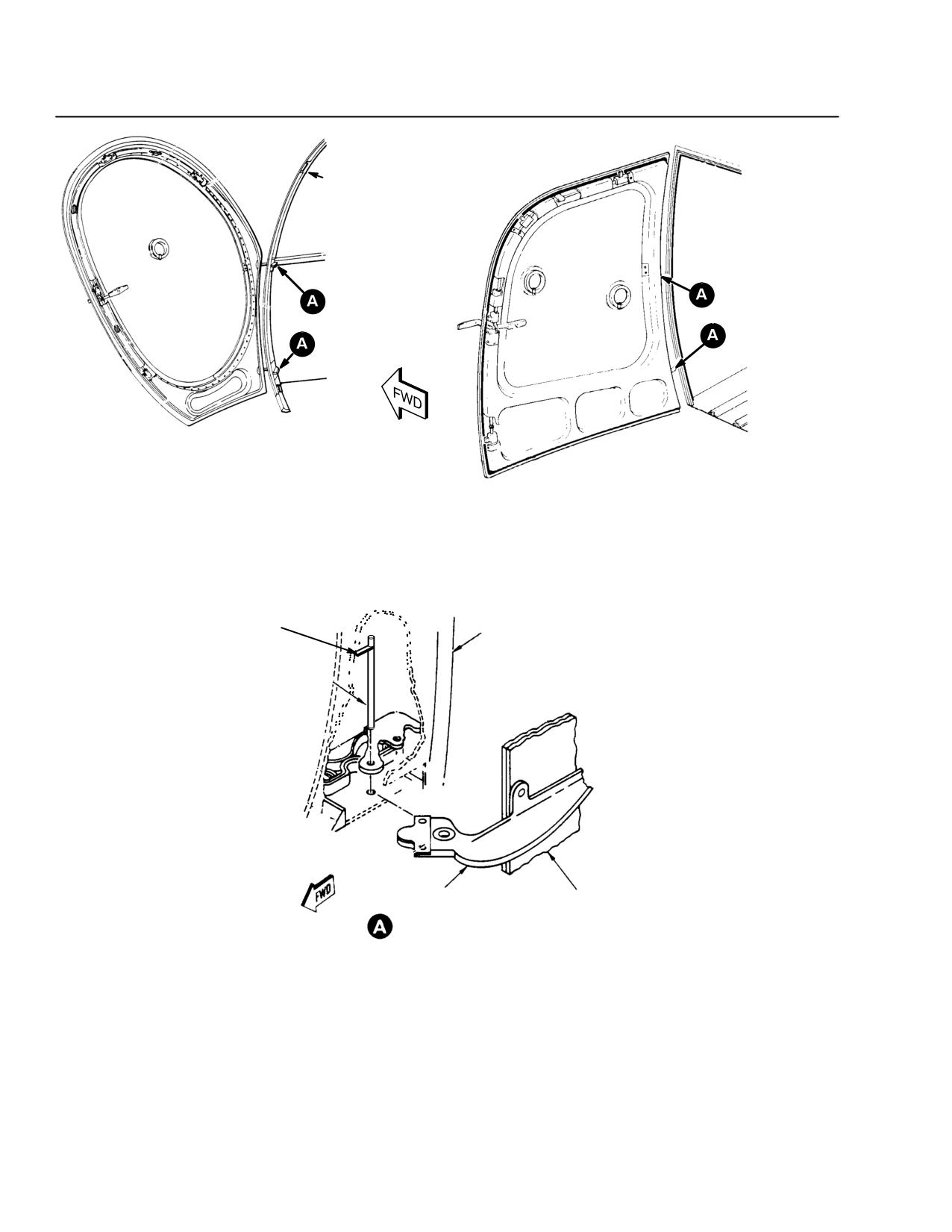
7-18. COCKPIT DOOR REMOVAL AND INSTALLATION
Door removal:
Open door.
Remove interior cover plates (pilot's side - remove fire extinguisher).
Pull lower hinge pin up to remove.
While holding door, rotate upper hinge pin until hinge pin tab clears the
slot and pull down on pin to remove.
Remove door.
Stow hinge pins and cover plates.
Door installation:
Place door hinges into door frame and hold open.
While holding door open, push in and rotate upper hinge pin until hinge
pin tab enters and fully seats in the slot.
Install lower hinge pin.
Install interior cover plates.
Install fire extinguisher (pilot's side).
Revision 18
7-19
CSP-E-1
ROTORCRAFT FLIGHT MANUAL
MD 500E
(Model 369E)
Handling, Servicing,
and Maintenance
DOOR FRAME
PILOT'S DOOR
PASSENGER/CARGO COMPARTMENT DOOR
(LH SHOWN, RH SIMILAR)
FUSELAGE
TAB
STRUCTURE
HINGE PIN
DOOR HINGE
DOOR
STRUCTURE
F60-043
Figure 7-5. Pilot and Passenger/Cargo Door Removal
7-20
Revision 18
MD 500E
ROTORCRAFT FLIGHT MANUAL
CSP-E-1
(Model 369E)
Handling, Servicing,
and Maintenance
7-19. SPECIAL OPERATIONAL CHECKS AND PROCEDURES
The following checks are typically utilized as part of a post maintenance run up
associated with scheduled inspections, troubleshooting or maintenance on specific
aircraft systems. Refer to the Handbook of Maintenance Instruction (HMI-2) for
the recommended use and frequency of the following checks.
COMPRESSOR WASH
Water wash provisions are incorporated in current configuration helicopters
(Ref. Figure 7-4).
Engine compressor cleaning should be performed by qualified personnel in ac-
cordance with the HMI and the Engine Operation and Maintenance Manual.
The following information is provided for pilots assisting qualified personnel in
the cleaning process.
The starter-generator can be used to motor the Rolls-Royce 250 Series en-
gine for compressor cleaning cycle.
Input voltage should be 24 vdc, but it is permissible to use 12 vdc.
To prevent starter-generator damage, duty cycle (cranking) time limits that
must not be exceeded are:
24 vdc External
24 vdc Helicopter
Auxiliary Power
Battery Power
25 Seconds ON
30 Seconds ON
30 Seconds OFF
2 Minutes OFF
25 Seconds ON
30 Seconds ON
30 Seconds OFF
2 Minutes OFF
25 Seconds ON
30 Seconds ON
30 Minutes OFF
30 Minutes OFF
12 vdc External Auxiliary Power
2 Minutes ON
30 Minutes OFF
2 Minutes ON
NOTE: Current required by starter-generator to maintain10 percent N1 rpm should be
approximately 150 amperes with 12 vdc input.
Revision 18
7-21
CSP-E-1
ROTORCRAFT FLIGHT MANUAL
MD 500E
(Model 369E)
Handling, Servicing,
and Maintenance
Procedures:
F Ensure engine anti-ice, cabin heat, and scav air (if installed) are off prior
to engine wash or rinse.
F Water injection will be started three seconds prior to starter engagement.
F Motor the engine with the twistgrip in CUTOFF.
F Release starter switch as necessary to maintain between 5% and 10% N1
speed during the wash/rinse.
F Water injection will continue during coast down until N1 stops.
F Allow engine to drain.
F Within 15 minutes of the water rinse, operate the engine at idle for five
minutes and actuate anti-ice, cabin heat, and scav-air (if installed) sys-
tems for one minute to purge and evaporate all residual water .
MAIN ROTOR HUB BALANCING
NOTE: Refer to HMI-2, Section 18-10-00. This procedure shall be performed by
qualified maintenance personnel only. Hub balancing is performed at 103% N2
with the main rotor blades removed.
F Follow the normal Pre-start and Engine Start procedures in Section IV
except:
Before starting, place governor increase/decrease switch at “minim-
um beep” by pressing and holding switch down for several seconds.
F After completing start, turn generator on and increase twistgrip to flight
idle: do not delay.
Observe N2 speed avoid range limits during this procedure and
CAUTION
exercise caution when increasing twistgrip to flight idle position to
avoid N2 overshoots.
F Using the governor increase/decrease switch, carefully increase N2 speed
to 103%.
After balance data is recorded:
F From 103% N2, shutdown engine.
NOTE: Shut down from 103% N2. Do not observe two minute cool-down at ground idle.
7-22
Revision 18
MD 500E
ROTORCRAFT FLIGHT MANUAL
CSP-E-1
(Model 369E)
Additional Operations
and Performance Data
S ECTION VIII
ADDITIONAL OPERATIONS
AND PERFORMANCE DATA
TABLE OF CONTENTS
PARAGRAPH
PAGE
8-1. Hover Ceiling - Out of Ground Effect (OGE)
8-1
Figure 8-1. Hover Ceiling Versus Gross Weight, Out of Ground Effect,
Takeoff Power, Two or Four Bladed Tail Rotor,
Rolls Royce 250-C20B
8-2
Figure 8-2. Hover Ceiling Versus Gross Weight, Out of Ground Effect,
Takeoff Power, Two or Four Bladed Tail Rotor
Rolls Royce 250-C20R/2
8-3
Figure 8-3. Hover Ceiling Versus Gross Weight, Out of Ground Effect,
Utility Floats Installed, Takeoff Power,
Rolls Royce 250-C20B
8-4
Revision 17
8-i
CSP-E-1
ROTORCRAFT FLIGHT MANUAL
MD 500E
(Model 369E)
Additional Operations
and Performance Data
This page intentionally left blank!
8-ii
Revision 17
MD 500E
ROTORCRAFT FLIGHT MANUAL
CSP-E-1
(Model 369E)
Additional Operations
and Performance Data
SECTION VIII
ADDITIONAL OPERATIONS AND
PERFORMANCE DATA
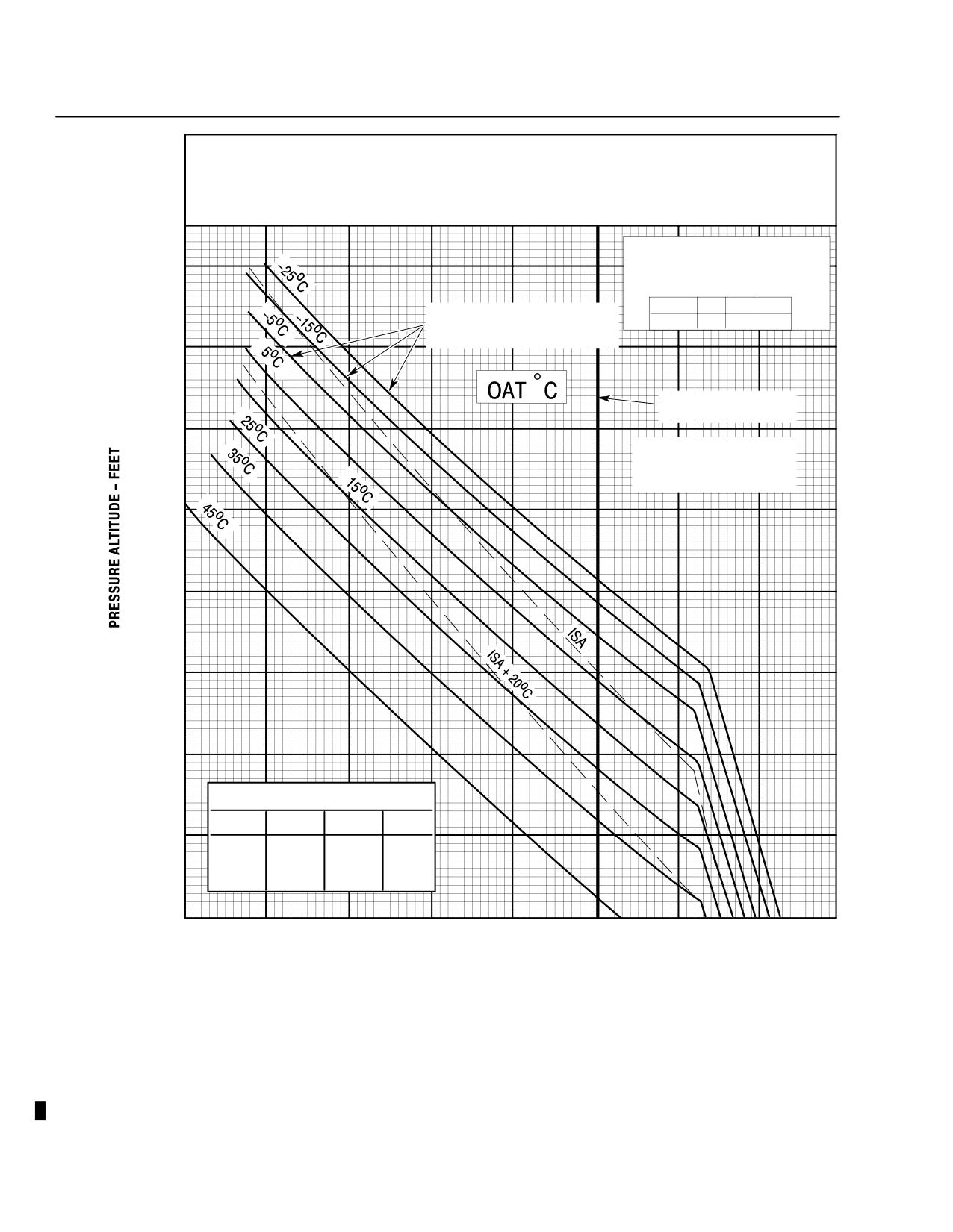
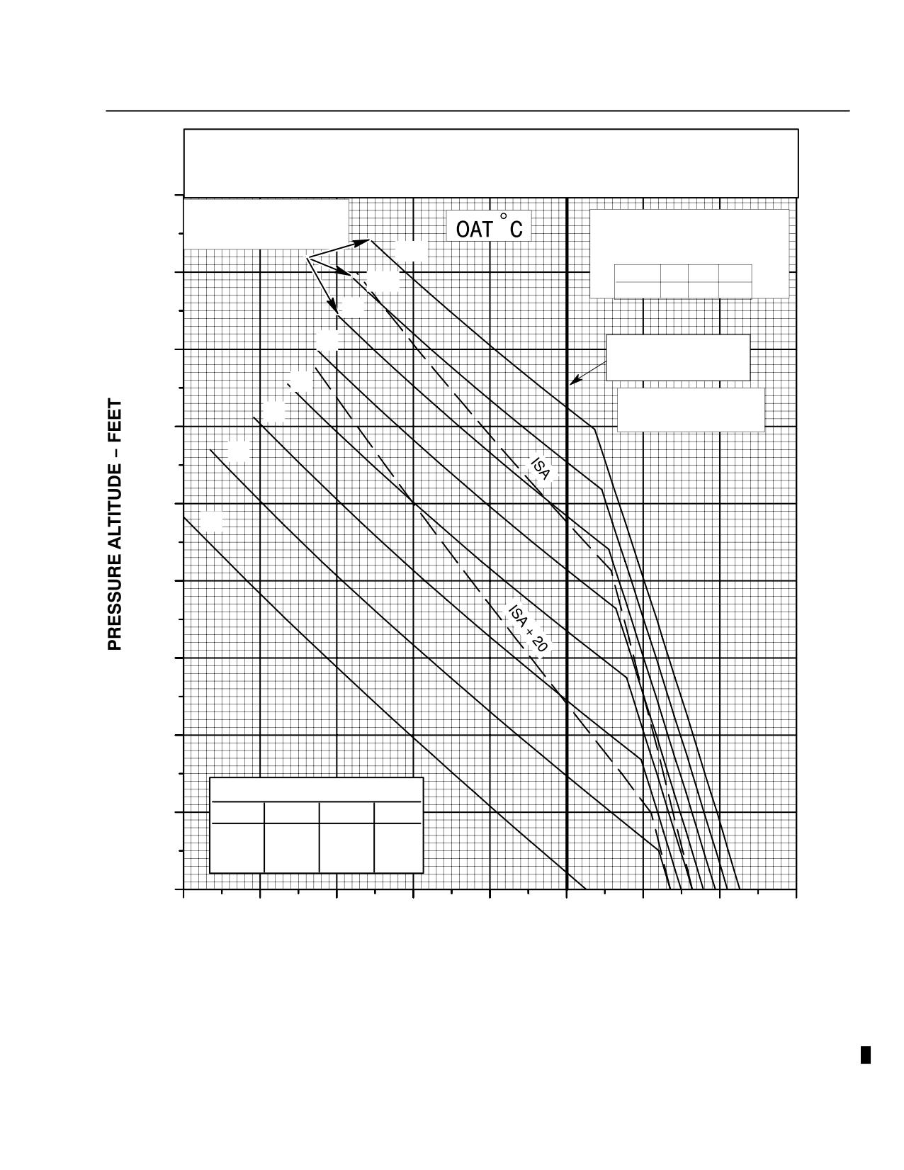
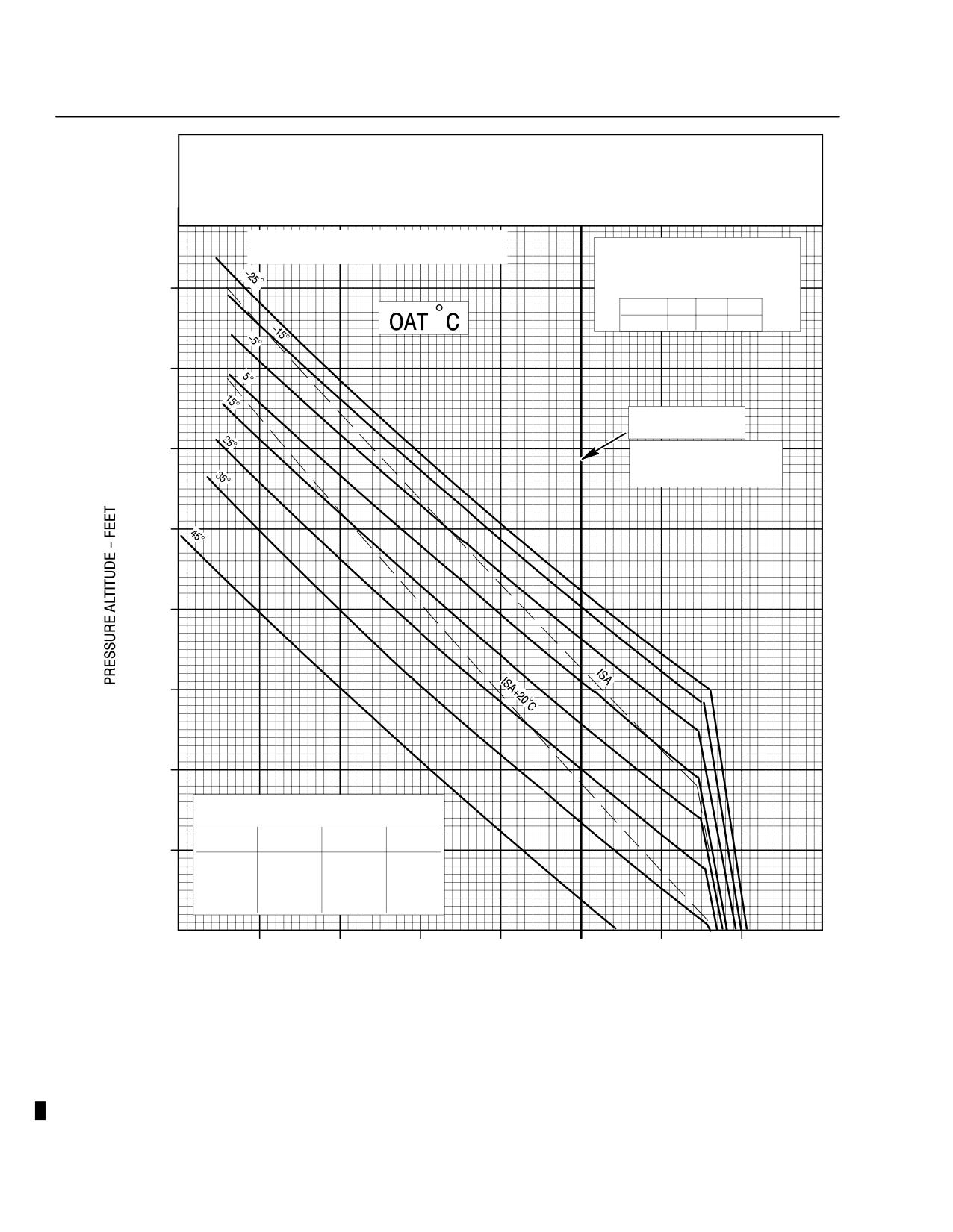
8-1. HOVER CEILING - OUT OF GROUND EFFECT (OGE)
Select the appropriate hover performance chart for the engine
CAUTION(Rolls Royce 250-C20B or 250-C20R/2) and/or optional equipment
installed.
Description:
The hover ceiling chart shows the maximum hover weight capability, out of
ground effect (OGE), at take off power for known conditions of pressure alti-
tude and outside air temperature, or alternately, the maximum hover ceiling
for a known gross weight and outside air temperature.
The hover ceiling vs gross weight charts are based on:
1. Takeoff power at 103% N2
2. Cabin heat and engine anti-ice OFF
3. Electrical load of 10 amps
4. Wind less than 3 knots
Use of chart:
To determine OGE hover performance, refer to Section V, Hover Ceiling
(IGE), ``Use of chart''.
NOTE: Aircraft with 4-bladed tail rotors:
Pilots should be aware that the IGE directional controllability tests have
demonstrated that the two-bladed tail rotor has more margin than the
four-bladed tail rotor. OGE directional controllability in winds greater than 3
knots has not been determined for either tail rotor configuration.
Revision 14
8-1
ROTORCRAFT FLIGHT MANUAL
MD 500E
CSP-E-1
(Model 369E)
Additional Operations
and Performance Data
THIS CHART BASED ON WINDS LESS THAN 3 KNOTS, CABIN HEAT, ENGINE ANTI-ICE OFF, ELECTRICAL LOAD 10 AMPERE,
APPLICABLE TO PARTICAL SEPARATOR (SCAVENGE OFF) OR STANDARD ENGINE AIR INLET.
REDUCE WEIGHT:
INCREASE WEIGHT:
50 LB WITH ABRASION STRIPS ON
1.
55 LB WITH SCAVENGE ON
MAIN ROTOR BLADES ONLY
2.
40 LB WITH MIST ELIMINATOR INSTALLED
DECREASE WEIGHT:
50 LB WITH ABRASION STRIPS ON
TAIL ROTOR BLADES ONLY
INCREASE (OR DECREASE) WT.
CAPABILITY LBS (ABOVE CRITICAL
16000
ALTITUDE) PER 10 AMP REDUCTION (OR
INCREASE) IN ELECTRICAL LOAD
NOT VERIFIED WHEN MAIN ROTOR
OAT°C
-5
15
35
BLADES HAVING ABRASION STRIPS
DWT
1
2
3
ARE INSTALLED
14000
MAXIMUM INTERNAL
GROSS WEIGHT
12000
GROSS WEIGHTS ABOVE
3000 LB MUST BE EXTERNAL
AND JETTISONABLE
10000
8000
6000
4000
REDUCE WEIGHT CAPABILITIES lbs AS FOLLOWS:
(APPLICABLE TO ALL TEMPERATURES)
PRESSURE
CABIN
ANTI-
BOTH
ALT. FT.
HEAT
ICE
2000
SL TO 4000
220
232
469
8000
152
157
306
12000
111
117
227
16000
86
89
172
0
2000
2200
2400
2600
2800
3000
3200
3400
3600
GROSS WEIGHT - POUNDS
F03-044-1
<<<< 250-C20B>>>>
Figure 8-1. Hover Ceiling Versus Gross Weight, Out of Ground Effect,
Takeoff Power, Two or Four Bladed Tail Rotor,
Rolls Royce 250-C20B
8-2
Revision 14
MD 500E
ROTORCRAFT FLIGHT MANUAL
CSP-E-1
(Model 369E)
Additional Operations
and Performance Data
THIS CHART BASED ON WINDS LESS THAN 3 KNOTS, CABIN HEAT, ENGINE ANTI-ICE OFF, ELECTRICAL LOAD 10
AMPERE, APPLICABLE TO
PARTICLE SEPARATOR (SCAVENGE OFF) OR STANDARD ENGINE AIR INLET
REDUCE WEIGHT:
INCREASE WEIGHT:
50LB WITH ABRASION STRIPS ON MAIN
ROTOR BLADES ONLY
1. 55LB WITH SCAVENGE ON
2. 40LB WITH MIST ELIMINATOR INSTALLED
DECREASE WEIGHT:
50LB WITH ABRASION STRIPS ON TAIL
ROTOR BLADES ONLY
18000
NOT VERIFIED WHEN
MAIN ROTOR BLADES
INCREASE (OR DECREASE) WT.
HAVING ABRASION STRIPS
CAPABILITY LBS (ABOVE CRITICAL
ARE INSTALLED
ALTITUDE) PER 10 AMP REDUCTION (OR
-25
IJNCREASE) IN ELECTRICAL LOAD
16000
OAT°C
-5
15
35
-15
DWT
1
2
3
-5
5
14000
MAXIMUM INTERNAL
GROSS WEIGHT
15
GROSS WEIGHTS ABOVE
25
3000 LB MUST BE EXTERNAL
AND JETTISONABLE
12000
35
10000
45
8000
6000
4000
REDUCE WEIGHT CAPABILITIES lbs AS FOLLOWS:
(APPLICABLE TO ALL TEMPERATURES)
PRESSURE
CABIN
ANTI-
BOTH
2000
ALT. FT.
HEAT
ICE
SL TO 4000
289
396
639
8000
256
316
557
12000
176
217
381
16000
129
157
278
0
2000
2200
2400
2600
2800
3000
3200
3400
3600
GROSS WEIGHT - POUNDS
<<<< 250-C20R/2>>>>
F03-044-2
Figure 8-2. Hover Ceiling Versus Gross Weight, Out of Ground Effect,
Takeoff Power, Two or Four Bladed Tail Rotor
Rolls Royce 250-C20R/2
Revision 14
8-3
ROTORCRAFT FLIGHT MANUAL
MD 500E
CSP-E-1
(Model 369E)
Additional Operations
and Performance Data
THIS CHART BASED ON CABIN HEAT, ENGINE ANTI-ICE OFF, ELECTRICAL LOAD 10 AMPERE, APPLICABLE TO
PARTICLE SEPARATOR (SCAVENGE OFF) OR STANDARD ENGINE AIR INLET
REDUCE WEIGHT:
INCREASE WEIGHT:
50LB WITH ABRASION STRIPS ON MAIN
ROTOR BLADES ONLY
1. 55LB WITH SCAVENGE ON
2. 40LB WITH MIST ELIMINATOR INSTALLED
DECREASE WEIGHT:
50LB WITH ABRASION STRIPS ON TAIL
18000
ROTOR BLADES ONLY
HOVER OGE BASED ON HUGHES TAHOE TEST
INCREASE (OR DECREASE) WT.
ADJUSTED TO BE CONSISTENT WITH IGE HOVER
CAPABILITY LBS (ABOVE CRITICAL
ALTITUDE) PER 10 AMP REDUCTION (OR
16000
INCREASE) IN ELECTRICAL LOAD
OAT°C
-5
15
35
DWT
1
2
3
14000
MAXIMUM INTERNAL
GROSS WEIGHT
12000
GROSS WEIGHTS ABOVE
3000 LB MUST BE EXTERNAL
AND JETTISONABLE
10000
8000
6000
4000
REDUCE WEIGHT CAPABILITIES lbs AS FOLLOWS:
(APPLICABLE TO ALL TEMPERATURES)
PRESSURE
CABIN
ANTI-
BOTH
ALT. FT.
HEAT
ICE
2000
SL TO 4000
220
232
469
8000
152
157
306
12000
111
117
227
16000
86
89
172
0
2000
2200
2400
2600
2800
3000
3200
3400
3600
GROSS WEIGHT - POUNDS
F03-048
<<<< 250-C20B >>>>
Figure 8-3. Hover Ceiling Versus Gross Weight, Out of Ground Effect,
Utility Floats Installed, Takeoff Power,
Rolls Royce 250-C20B
8-4
Revision 14
MD 500E
ROTORCRAFT FLIGHT MANUAL
CSP-E-1
(Model 369E)
Optional Equipment
S E C T I O N IX
OPTIONAL EQUIPMENT
TABLE OF CONTENTS
PARAGRAPH
PAGE
9-1.
General Information
9-1
9-2.
Listing - Optional Equipment
9-1
Table 9-1. Optional Equipment - Model 369E Helicopter
(250-C20B or C20R/2)
9-2
Table 9-2. Optional Equipment - Model 369E Helicopter (250-C20B)
9-2
9-3.
Optional Equipment Performance Data
9-3
9-4.
Compatibility - Combined Optional Equipment
9-3
Table 9-3. Optional Equipment Kit Compatibility - Model 369E Helicopter
9-3
9-5.
Operating Instructions: Cargo Hook Kit
9-5
Figure 9-1. VNE Placards - C20B or C20R/2 Engine
9-7
Figure 9-2. Cargo Hook Release - Electrical and Mechanical
9-8
Figure 9-3. Cargo Hook
9-10
9-6.
Operating Instructions: Anti-Ice Airframe Fuel Filter
9-13
Figure 9-4. Anti-Ice Airframe Fuel Filter
9-16
9-7.
Operating Instructions: Four-Bladed Tail Rotor
9-17
Table 9-4. Center of Gravity Limits
9-21
Figure 9-5. Longitudinal Center of Gravity Limits
9-22
Figure 9-6. Lateral Center of Gravity Limits
9-23
9-8.
Operating Instructions - Emergency Floats
9-25
Figure 9-7. VNE Placards - Rols Royce 250-C20B (Sheet 1 of 2)
9-28
Figure 9-7. VNE Placards - Rolls Royce 250-C20B (Sheet 2 of 2)
9-29
Figure 9-8. VNE Placards - Rolls Royce 250-C20R/2 (Sheet 1 of 2)
9-30
Figure 9-8. VNE Placards - Rolls Royce 250-C20R/2 (Sheet 2 of 2)
9-31
Figure 9-9. Float Pressure Gauge
9-34
9-9.
Operating Instructions - Engine Air Inlet Diverter
9-35
Figure 9-10. VNE Placards (Sheet 1 of 2)
9-36
Figure 9-10. VNE Placards (Sheet 2 of 2)
9-37
9-10. Operating Instructions - Utility Floats
9-39
Figure 9-11. VNE Placards (Sheet 1 of 2)
9-42
FAA Approved
Revision 14
9-i
MD 500E
CSP-E-1
ROTORCRAFT FLIGHT MANUAL
(Model 369E)
Optional Equipment
PARAGRAPH
PAGE
Figure 9-11. VNE Placards (Sheet 2 of 2)
9-43
Figure 9-12. Height-Velocity Diagram - Utility Floats Installed
9-46
Figure 9-13. Airspeed Calibration Curve - Utility Floats Installed
9-47
9-11. Operating Instructions: Garmin G500H Integrated System
9-49
Figure 9-14. Instrument Panel, LH Command - Layout Typical
9-52
Figure 9-15. Instrument Panel, RH Command - Layout Typical
9-53
Figure 9-16. Runtime (Hobbs) Meter, OAT Probe and NAV/COM
Antenna Locations - Typical
9-54
FAA Approved
9-ii
Revision 18
MD 500E
ROTORCRAFT FLIGHT MANUAL
CSP-E-1
(Model 369E)
Optional Equipment
SECTION IX
OPTIONAL EQUIPMENT
9-1. GENERAL INFORMATION
This section provides general supplemental information on optional equipment
for the MD 500E Helicopter. The information includes a listing of usable op-
tional equipment and compatibility of combined equipment on the helicopter.
Supplemental data is prepared and included in this section whenever the in-
stallation of that equipment affects the FAA Approval Data for Limitations
(Section II), Emergency and Malfunction Procedures (Section III), Normal Pro-
cedures (Section IV), and Performance Data (Section V).
The Flight Manual Supplemental Data is to be used in conjunction with the
basic Flight Manual data and takes precedence over that data when the equip-
ment is installed.
Be sure to include a review of the appropriate flight manual
CAUTIONsupplemental data for type of optional equipment installed
(including STC items) as a regular part of preflight planning.
9-2. LISTING - OPTIONAL EQUIPMENT
Table 9-1 lists MDH optional equipment items available that require additional
operating instructions. This table does not include non-MDHI STC items that
may be FAA approved for use. Other optional equipment items may be found
in the HMI. These kits are approved and usable on the 369E Helicopter
Equipped with either the Rolls Royce 250-C20B or C20R/2 engines.
Table 9-2 lists optional equipment kits and flight manual supplements ap-
proved and usable on the 369E Helicopter equipped with the 250-C20B engine
only. This table does not include non-MDHI STC items that may be FAA ap-
proved for use.
SPECIAL NOTE:
Items in the table marked with an asterisk (*) are optional equipment items that
have had their supplemental data incorporated into the main body of the flight
manual and are identified by the statement, ``If installed''.
FAA Approved
Revision 14
9-1
CSP-E-1
ROTORCRAFT FLIGHT MANUAL
MD 500E
(Model 369E)
Optional Equipment
Table 9-1. Optional Equipment - Model 369E Helicopter (250-C20B or C20R/2)
Publication
Equipment
No.
*Pitot heat
CSP-E-1
*Extended landing gear
CSP-E-1
*Rotor brake
CSP-E-1
*Engine air particle separator filter
CSP-E-1
Cargo hook
CSP-E-1 Section IX
Emergency floats
CSP-E-1 Section IX
Four-bladed T/R
CSP-E-1 Section IX
*Indicates data incorporated into the flight manual (Sections I thru VII where appropriate).
NOTE: See Table 9-2 for Optional Equipment Supplements certified for model 369E
helicopters equipped with Allison Model 250-C20B engines only.
Table 9-2. Optional Equipment - Model 369E Helicopter (250-C20B)
Publication
Equipment
No.
Anti-ice airframe fuel filter
CSP-E-1 Section IX
Engine air inlet diverter kit
CSP-E-1 Section IX
Rotorcraft utility floats
CSP-E-1 Section IX
FAA Approved
9-2
Revision 14
MD 500E
ROTORCRAFT FLIGHT MANUAL
CSP-E-1
(Model 369E)
Optional Equipment
9-3. OPTIONAL EQUIPMENT PERFORMANCE DATA
SPECIAL NOTE:
Optional equipment that affect hover performance require addition-
al hover performance charts. Optional Equipment IGE hover perfor-
mance charts are located in Section V and Optional Equipment OGE
hover performance charts are located in Section VIII.
9-4. COMPATIBILITY - COMBINED OPTIONAL EQUIPMENT
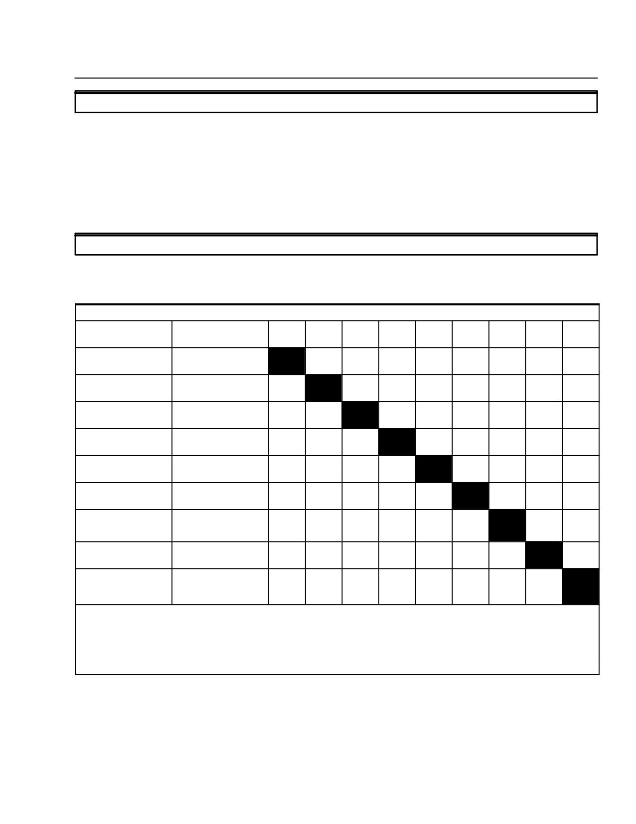
Table 9-3. Optional Equipment Kit Compatibility - Model 369E Helicopter
Compatibility: Blank=Yes; X=No
Optional
Part Number
A.
B.
C.
D.
E.
F.
G.
H.
I.
Equipment
(369H/369D)
290121
290007
292500
90022
90148
90072
290086
292044
292044
A. Emergency Floats
369D290121-527
X
(1)
X
(2)
B. Extended Landing
369D290007-501, -50
Gear
3,-509, -511
C. Four-Bladed Tail
369D292500
X
X
Rotor
D. Anti-Ice Airframe
369H90022-503
X
Fuel Filter
E. Engine Air Particle
369H90148-519, -521,
Separator Kit
-535, -537, -539
F. Cargo Hook
369H90072-505
(1)
(2)
G. Utility Floats (3)
369D290086-501,
X
X
X
-503
H. Engine Air Inlet
369D292044-501,
X
Diverter Kit
369D292045
I.
250-C20R/2
369D298000
X
X
X
Engine Installa-
tion
Notes:
(1)
Cyclic stick grip kit 369H90129-505 must be installed.
(2)
For functional use of Cargo Hook, emergency floats must be in stowed configuration for either standard or
extended landing gear.
(3)
Not compatible with 369H90045, *(wheel, pneumatic) or standard landing gear.
*Remove before flight.
FAA Approved
Revision 17
9-3
CSP-E-1
ROTORCRAFT FLIGHT MANUAL
MD 500E
(Model 369E)
Optional Equipment
This page intentionally left blank!
FAA Approved
9-4
Revision 17
MD 500E
ROTORCRAFT FLIGHT MANUAL
CSP-E-1
(Model 369E)
Optional Equipment
Cargo Hook Kit
9-5. OPERATING INSTRUCTIONS: CARGO HOOK KIT
PART I
GENERAL
The MDHI 369H90072-505 Cargo Hook Kit consists of a cargo hook which at-
taches to the fuselage keel beam, electrical connections to provide the pilot
with cargo release or jettison capability using a switch on the cyclic stick, and
a manual backup release mechanism. The cargo hook kit is designed to carry
hook loads up to 2000 pounds.
When the kit is installed, an owner or operator holding a valid Rotorcraft Ex-
ternal Load Operator Certificate may utilize the helicopter for transportation of
external cargo when operated by a qualified pilot. OPERATIONS WITH CAR-
GO ON THE HOOK SHALL BE CONDUCTED IN ACCORDANCE WITH AP-
PLICABLE PORTIONS OF FEDERAL AVIATION REGULATIONS PART 133.
Information provided in these operating instructions is presented with the in-
tent of furnishing important data that can be used in the Rotorcraft Load
Combination Flight Manual. The Combination Flight Manual, which is re-
quired by FAR Part 133, will be prepared by the applicant to obtain the rotor-
craft External Load Operator Certificate.
FAA Approved
Revision 14
9-5
CSP-E-1
ROTORCRAFT FLIGHT MANUAL
MD 500E
(Model 369E)
Optional Equipment
Cargo Hook Kit
PART II
LIMITATIONS
Weight Limitations:
Maximum takeoff and landing gross weight 3000 pounds. Weight
CAUTIONin excess of 3000 pounds must be external and jettisonable.
Maximum Rotorcraft - Load Combinations operating gross weight 3550
pounds (FAR 133).
Center of Gravity Limitations:
Center of gravity not to exceed the limits certificated for the basic helicop-
ter.
For gross weights greater than 3000 pounds, center of gravity limits for
3000 pounds apply.
Cargo Hook Limitations:
Cargo hook structural load limit is 2000 pounds.
Airspeed Limitations:
With no load on hook, airspeed limits are unchanged.
With load on hook, airspeed limits are presented on the exterior load VNE
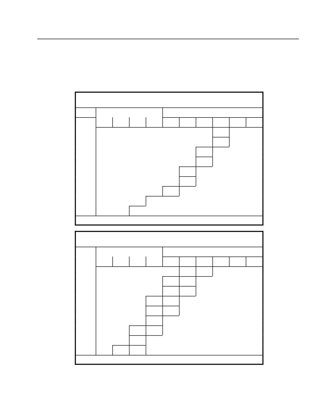
placards. The airspeed presented on these placards apply to either C20B or
C20R/2 engine installations.
NOTE: Use caution as size and shape of load, and load attaching cable size and length
may affect flight characteristics. Satisfactory flight characteristics have been
demonstrated with a compact 2000 pound load suspended on a 3/8-inch cable
5 feet long.
Altitude Limitations:
Maximum operating altitude is 14,000 feet density altitude.
FAA Approved
9-6
Revision 14
MD 500E
ROTORCRAFT FLIGHT MANUAL
CSP-E-1
(Model 369E)
Optional Equipment
Cargo Hook Kit
Placards:
Make placards stating approved load class(es) and occupancy limitations.
Display placards in a conspicuous location in cockpit.
Placard stating, ``External Load Limit 2000 Pounds'' installed on or next to
cargo hook.
EXTERIOR LOAD
VNE IAS (KNOTS)
OAT
PRESS ALT X 1000
GROSS WT = 3200 LB OR LESS
°C
0
2
4
6
8
10
12
14
16
18
−30
75
−20
65
−10
75
0
66
10
80
77
20
68
30
79
NO FLIGHT
40
45
EXTERIOR LOAD
VNE IAS (KNOTS)
OAT
PRESS ALT X 1000
GROSS WT = 3201 TO 3550 LB
°C
0
2
4
6
8
10
12
14
16
18
−30
72
59
−20
79
65
−10
72
59
0
79
66
10
80
73
59
20
66
30
74
61
NO FLIGHT
40
68
45
78
65
Figure 9-1. VNE Placards - C20B or C20R/2 Engine
FAA Approved
Revision 14
9-7
CSP-E-1
ROTORCRAFT FLIGHT MANUAL
MD 500E
(Model 369E)
Optional Equipment
Cargo Hook Kit
PART III
EMERGENCY AND
MALFUNCTION PROCEDURES
ENGINE FAILURE:
The presence of an external load may further complicate a failed engine
condition. Release of loads attached through the cargo hook should be ac-
complished as soon as practical; consistent with other safety of flight factors
(rotor RPM, altitude, airspeed, ground personnel safety, etc).
EMERGENCY RELEASE:
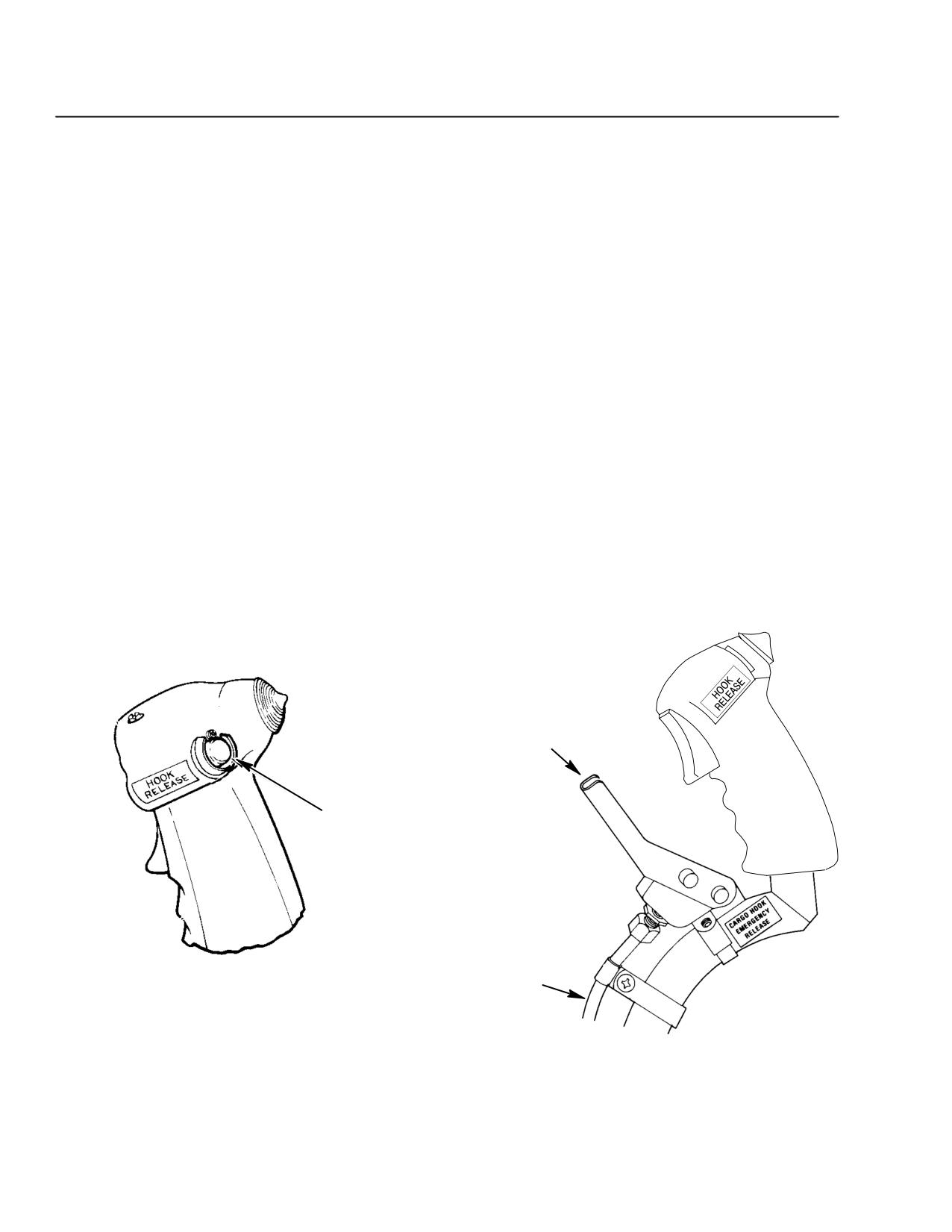
Actuate mechanical release handle to release cargo in the event of an elec-
trical failure. Operate handle quickly and deliberately (Ref. Figure 9-2).
NOTE: Ground support personnel should manually assure positive reset of the cargo
hook after use of mechanical release, prior to further cargo pickups.
Static electricity discharge:
Instruct ground crew to insure that the helicopter has been electrically
grounded prior to attaching cargo to drain charges of static electricity that
may build up in flight.
CARGO HOOK MECHANICAL RELEASE
CARGO HOOK
ELECTRICAL RELEASE
CYCLIC-MOUNTED ELECTRICAL HOOK RELEASE
CARGO HOOK
RELEASE CABLE
MECHANICAL HOOK RELEASE
Figure 9-2. Cargo Hook Release - Electrical and Mechanical
FAA Approved
9-8
Revision 14
MD 500E
ROTORCRAFT FLIGHT MANUAL
CSP-E-1
(Model 369E)
Optional Equipment
Cargo Hook Kit
PART IV
NORMAL PROCEDURES
Normal Operation:
Preflight
Place battery switch in BAT position and check that HOOK circuit
breaker is in.
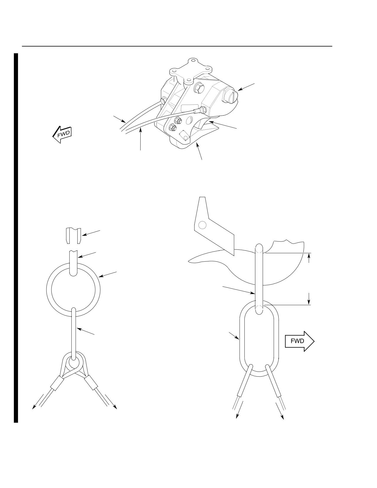
Push cargo load ring into hook throat. Cargo hook keeper should permit
easy entrance into throat. Leave ring in hook for remainder of operation-
al checks (Ref. Figure 9-3).
Pull aft and downward on load ring; hook must remain in locked posi-
tion.
Operational Checks
Check electrical and emergency operation of cargo hook release (Ref.
Figure 9-3).
Check operation of external release knob (located on left side of cargo
hook body).
Hook should return to the closed position after above checks.
Move pilot's cyclic to all extreme positions. Cargo hook must remain
locked and external release knob must not rotate.
With load ring in cargo hook, swing hook to the limits of trav-
el in all directions. Hook must remain in the closed position.
Inflight
Check cargo HOOK circuit breaker IN.
Use care to avoid passing load attaching cables over landing gear
CAUTIONskid tube when attaching load to hook with helicopter on the
ground.
Apply collective smoothly when lifting cargo.
Activate cargo release switch on cyclic stick to release cargo.
FAA Approved
Revision 17
9-9
CSP-E-1
ROTORCRAFT FLIGHT MANUAL
MD 500E
(Model 369E)
Optional Equipment
Cargo Hook Kit
EXTERNAL RELEASE
(TURN CLOCKWISE)
ELECTRICAL WIRE HARNESS
KEEPER
MANUAL RELEASE CABLE
HOOK (LOAD BEAM)
KEEPER
KEEPER
CORRECT RIGGING
LOAD ARM
LOAD
ARM
INSIDE
PRIMARY CIRCULAR RING
DIAMETER
ENGAGING LOAD ARM
CIRCULAR
PRIMARY
PRIMARY
LOAD RING
LOAD RING
SECONDARY LOAD MEMBER
SECONDARY MEMBER
(RING OR SHACKLE)
VIEW LOOKING
FORWARD
TO LOAD
TO LOAD
TO LOAD
F60-052-3
Figure 9-3. Cargo Hook
FAA Approved
9-10
Revision 17
MD 500E
ROTORCRAFT FLIGHT MANUAL
CSP-E-1
(Model 369E)
Optional Equipment
Cargo Hook Kit
PART V
PERFORMANCE DATA
Refer to Section V for IGE hover performance or Section VIII for OGE hover
performance to assist in planning operations with the cargo hook.
PART VI
WEIGHT AND BALANCE DATA
The following table of Cargo Hook Loading Data should be used by the opera-
tor to assist in evaluating the helicopter center of gravity for various hook load
weights.
Cargo Hook Loading Data:
Cargo Longitudinal CG = 99.3
Cargo Weight
Moment/100
(lb)
(in.-lb)
100
99
200
199
300
298
400
397
500
497
600
596
700
695
800
794
900
894
1000
993
1100
1092
1200
1191
1300
1291
1400
1390
1500
1490
1600
1589
1700
1688
1800
1787
1900
1887
2000
1986
FAA Approved
Revision 17
9-11
CSP-E-1
ROTORCRAFT FLIGHT MANUAL
MD 500E
(Model 369E)
Optional Equipment
Cargo Hook Kit
This page intentionally left blank!
FAA Approved
9-12
Revision 17
MD 500E
ROTORCRAFT FLIGHT MANUAL
CSP-E-1
(Model 369E)
Optional Equipment
Four-Bladed Tail Rotor
9-6. OPERATING INSTRUCTIONS: ANTI-ICE AIRFRAME FUEL FILTER
PART I
GENERAL
The MDHI Anti-Ice Airframe Fuel Filter is designed to strip the fuel of ice
particles prior to entering the engine fuel system. Installation of the filter
will delete the requirement for use of fuel containing anti-ice additives.
The anti-ice airframe fuel filter incorporates a filter unit mounted in series
between the aircraft fuel system and the engine fuel system. Electrical and
mechanical equipment sense the build-up of ice in the filter unit and will
automatically illuminate a cockpit caution on the annunciator panel. The pi-
lot then actuates a switch to activate the aircraft start pump. When the fil-
ter becomes fully clogged, a by-pass valve contained in the filter unit opens
and the fuel by-passes the filter element.
FAA Approved
Revision 14
9-13
CSP-E-1
ROTORCRAFT FLIGHT MANUAL
MD 500E
(Model 369E)
Optional Equipment
Four-Bladed Tail Rotor
PART II
LIMITATIONS
Altitude limitations:
If ground temperature prior to flight is 5°C or less, flight operations are
limited to 12,000 feet pressure altitude maximum.
If ground temperature prior to flight is above 5°C, flight operations are lim-
ited to 14,000 feet pressure altitude maximum, but not to exceed limitations
of Basic RFM Section II.
Anti-Ice fuel additives:
Installation of the Anti-Ice Airframe Fuel Filter eliminates the need for
anti-ice fuel additives in the fuel (i.e., Prist).
Placards:
Anti-Ice Airframe Fuel Filter Installation
For ground temp of 5°C or less max ALT 12,000 HP.
For ground temp greater than 5°C max ALT 14,000 HP.
PART III
EMERGENCY AND
MALFUNCTION PROCEDURES
ANTI-ICE AIRFRAME FUEL FILTER
AIR
Indications: Yellow
caution indicator ON.
FRAME
FILTER
Conditions: Anti-ice airframe fuel filter becoming clogged with ice or other solid
contaminants.
Procedures:
F Turn start pump ON.
F Land as soon as practical.
FAA Approved
9-14
Revision 14
MD 500E
ROTORCRAFT FLIGHT MANUAL
CSP-E-1
(Model 369E)
Optional Equipment
Four-Bladed Tail Rotor
PART IV
NORMAL PROCEDURES
Preflight checks:
Battery switch - BAT or EXT PWR
Start Pump - ON
Do not open drain valve unless start pump is ON. An unexpected
WARNING
flameout or power loss may occur if air is allowed to enter the fuel
system.
Drain any residual water in the filter unit through the drain valve on the
bottom of the filter unit.
NOTE: If aircraft has been exposed to freezing temperatures, failure to drain may be due
to ice formation in the filter element.
Start Pump - OFF
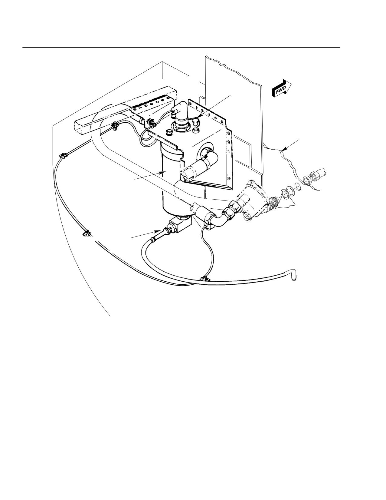
Press red press-to-test button located on the top of filter unit (Ref.
Figure 9-4); AIR FRAME FILTER light should come on.
Release press-to-test button; AIR FRAME FILTER light should go out.
Post flight filter cleaning:
When ambient temperature is expected to go below freezing, any water in
the filter unit should be drained following completion of the flight.
Following any actuation of AIR FRAME FILTER light, fuel filter should be
serviced (Ref. HMI-2).
FAA Approved
Revision 14
9-15
CSP-E-1
ROTORCRAFT FLIGHT MANUAL
MD 500E
(Model 369E)
Optional Equipment
Four-Bladed Tail Rotor
TEST BUTTON
FIREWALL
FILTER BOWL
ANTI-ICE DRAIN VALVE
Figure 9-4. Anti-Ice Airframe Fuel Filter
FAA Approved
9-16
Revision 14
MD 500E
ROTORCRAFT FLIGHT MANUAL
CSP-E-1
(Model 369E)
Optional Equipment
Four-Bladed Tail Rotor
9-7. OPERATING INSTRUCTIONS: FOUR-BLADED TAIL ROTOR
PART I
GENERAL
The MDHI Four-Bladed Tail Rotor Kit has been developed to reduce the exter-
nal noise signature of the helicopter. It consists of two principal assemblies, a
four bladed tail rotor, and gearbox. The pedal bungee has been changed to
compensate for tail rotor produced loads.
There is a weight increase of 9.4 pounds which will cause an aft C.G. shift of
0.6 to 0.9 inch depending on gross weight. The exact shift must be determined
by individual helicopter weight and balance.
The four-bladed tail rotor turns at reduced RPM thus substantially reducing
the external noise signature which is a function of rotor tip speed.
FAA Approved
Revision 14
9-17
CSP-E-1
ROTORCRAFT FLIGHT MANUAL
MD 500E
(Model 369E)
Optional Equipment
Four-Bladed Tail Rotor
PART II
LIMITATIONS
Flight restrictions:
NOTE: MD 500E (Model 369E) helicopters equipped with the Allison 250-C20R/2
engine and the four-bladed tail rotor kit are approved in combination only with
the optional equipment depicted in Section IX, Table 9-3.
Rotor speed limits:
Minimum RPM: Power Off 415 NR (lower red bar on rotor tachometer).
Center of gravity envelope:
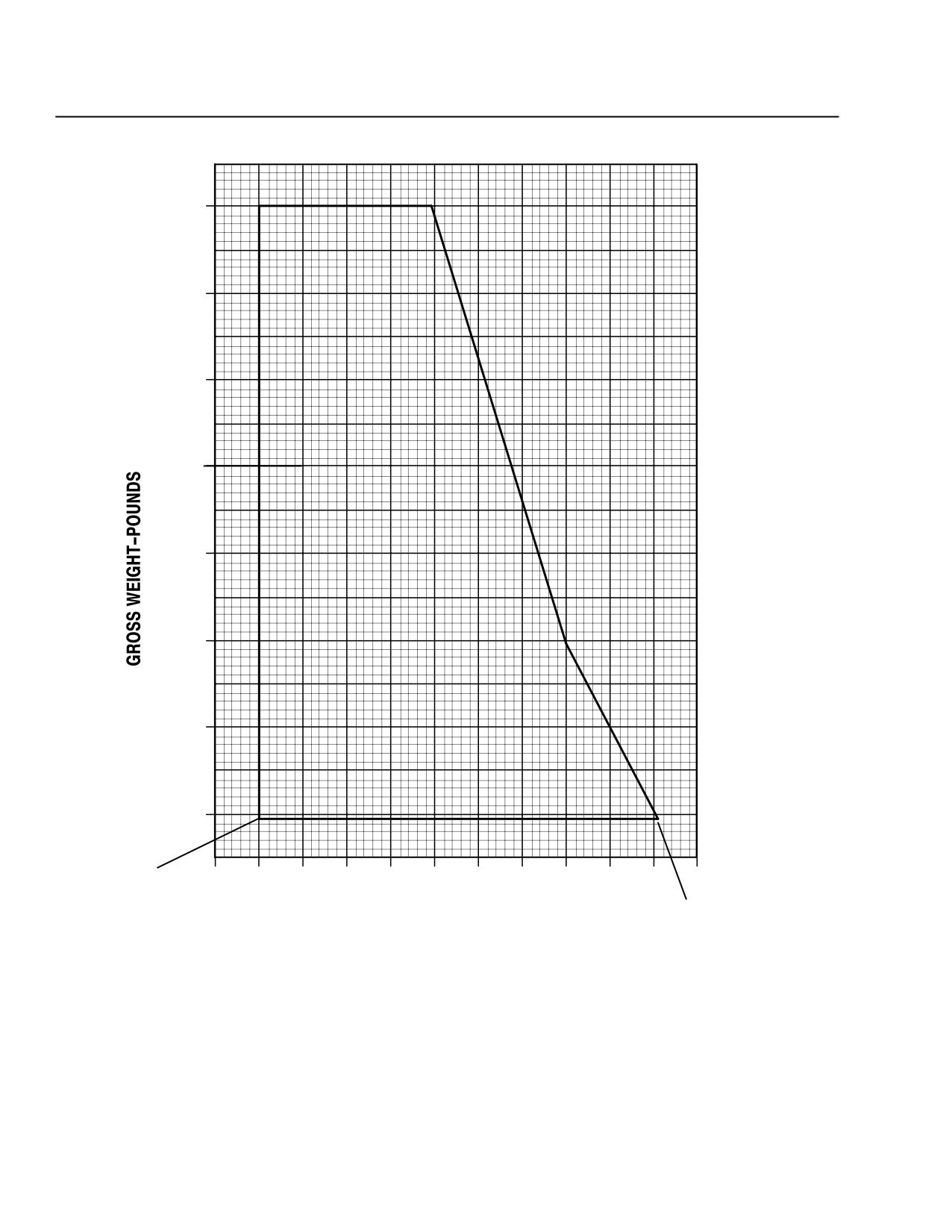
The forward CG limit is 99.0 inches; the aft CG varies linearly from 103.0
inches at 3000 pounds gross weight, to 106.0 at 2000 pounds, then linearly
to 108.1 at minimum flying weight of 1592 pounds (Ref. Table 9-4).
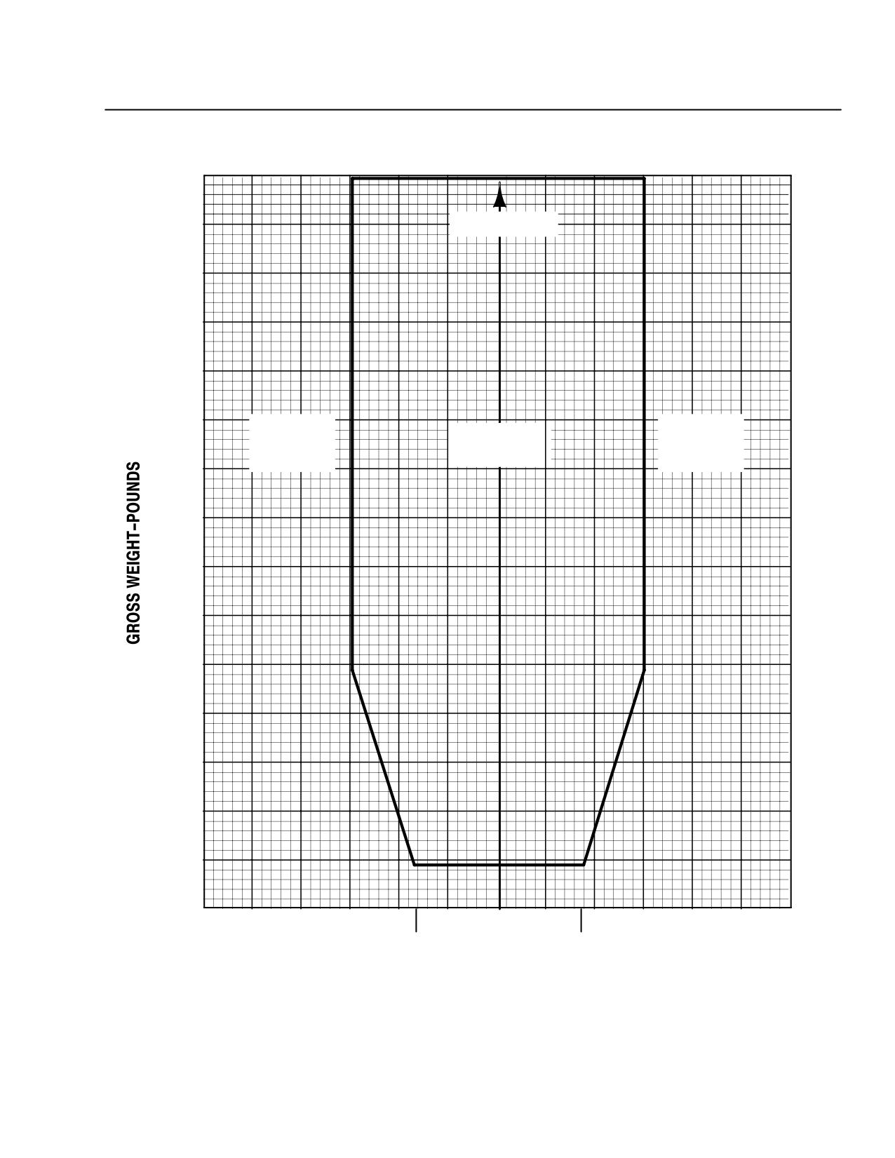
The lateral CG limits are ±3.0 inches at gross weights from 3000 to 2000
pounds, then vary linearly to ±1.7 inches at 1592 (Ref. Table 9-4).
FAA Approved
9-18
Revision 14
MD 500E
ROTORCRAFT FLIGHT MANUAL
CSP-E-1
(Model 369E)
Optional Equipment
Four-Bladed Tail Rotor
PART III
EMERGENCY AND
MALFUNCTION PROCEDURES
ENGINE FAILURE
Conditions: In flight.
Procedures:
F Allow the speed to reduce to 130 knots IAS or lower (see VNE placard).
Maintain rotor speed between 415 and 523 RPM by use of collective con-
trol.
F Maximum gliding distance is obtained at 80 knots and 415NR.
F Minimum rate of descent is obtained at 60 knots and 415NR.
PART IV
NORMAL PROCEDURES
Preflight check:
F Output shaft dust cover, retaining nut,
tang washer, and rubber bumper
CHECK
NOTE: Deformation of the teetering stop support portion of the retaining nut may indicate
that excessive T/R flapping has occurred and should be inspected in accordance
with the HMI prior to flight.
Engine start:
F Pedals
NEUTRAL
Excessive tail rotor flapping will result if pedals are not in neutral position.
CAUTION
NOTE: The pedal bungee is an overcenter type. Consequently, if not restrained, the
pedals will snap from one side to the other when moving through its load center
position.
FAA Approved
Revision 14
9-19
CSP-E-1
ROTORCRAFT FLIGHT MANUAL
MD 500E
(Model 369E)
Optional Equipment
Four-Bladed Tail Rotor
Low speed maneuvering:
Certain maneuvers may cause extreme T/R flapping and pounding
CAUTIONof the T/R teetering stop support portion of the retaining nut (felt
and heard by the pilot as a momentary medium frequency vibration).
These maneuvers usually involve rapid yaw rates that allow the
T/R to pass through the relative wind line. Maneuvers such as
simulating a T/R failure in a hover, rapid pedal turns at speeds
above translational lift, and uncoordinated agricultural type turns
may fall into this category and should be avoided.
Repeated pounding of the stop support may lead to the shearing
of the inner key on the tang washer and subsequent loosening
of the retaining nut.
Practice autorotation:
Practice autorotation should be conducted at 130 knots IAS or below (see
VNE placards). Maintain rotor speed between 415 and 523 RPM by use of
collective control.
Maximum gliding distance is obtained at 80 knots; 415NR.
Minimum rate of descent is obtained at 60 knots; 415NR.
Engine/aircraft shut down:
Maintain pedals in center position until rotor has stopped turning to pre-
CAUTION
vent excessive tail rotor flapping.
PART V
PERFORMANCE DATA
Hover performance:
IGE controllability has been demonstrated to be adequate in winds up to 17
knots from any direction - the least favorable wind azimuth, which would
have the least left pedal margin, is 45 degrees right of the nose.
Refer to Section V for IGE hover performance.
FAA Approved
9-20
Revision 14
MD 500E
ROTORCRAFT FLIGHT MANUAL
CSP-E-1
(Model 369E)
Optional Equipment
Four-Bladed Tail Rotor
PART VI
WEIGHT AND BALANCE DATA
Weight and balance characteristics:
See Table 9-4 and Figure 9-5 and Figure 9-6 for CG limits.
Table 9-4. Center of Gravity Limits
Gross Weight
Longitudinal C.G. Limit
Lateral C.G. Limit
(lb)
(Sta-in.)
(Sta-in.)
Forward
Aft
(+) Right, (-) Left
3000
99.0
103.0
±3.0
2500
99.0
104.5
±3.0
2300
99.0
105.1
±3.0
2000
99.0
106.0
±3.0
1592
99.0
108.1
±1.7
The forward CG limit is 99.0 inches; the aft CG varies linearly from 103.0
inches at 3000 pounds gross weight, to 106.0 at 2000 pounds, then linearly
to 108.1 at minimum flying weight of 1592 pounds.
The lateral CG limits are ±3.0 inches at gross weights from 3000 to 2000
pounds, then vary linearly to ±1.7 inches at 1592 pounds.
FAA Approved
Revision 14
9-21
CSP-E-1
ROTORCRAFT FLIGHT MANUAL
MD 500E
(Model 369E)
Optional Equipment
Four-Bladed Tail Rotor
3000
2800
2600
2400
2200
2000
1800
1600
1592 LB
98
99
100
101
102
103
104
105
106
107
108
109
108.1
LONGITUDINAL ARM - INCHES
F03-042
Figure 9-5. Longitudinal Center of Gravity Limits
FAA Approved
9-22
Revision 14
MD 500E
ROTORCRAFT FLIGHT MANUAL
CSP-E-1
(Model 369E)
Optional Equipment
Four-Bladed Tail Rotor
3000
FORWARD
2800
2600
(+) RIGHT
(-) LEFT
AIRCRAFT
LATERAL
LATERAL
CG LIMIT
CENTERLINE
CG LIMIT
2400
2200
2000
1800
1592-
1600
1500
-5
-4
-3
-2
-1
0
+1
+2
+3
+4
+5
-1.7
+1.7
LATERAL ARM-INCHES
F03-043
Figure 9-6. Lateral Center of Gravity Limits.
FAA Approved
Revision 14
9-23
CSP-E-1
ROTORCRAFT FLIGHT MANUAL
MD 500E
(Model 369E)
Optional Equipment
Four-Bladed Tail Rotor
PART VII
HANDLING SERVICING
AND MAINTENANCE
Servicing materials for the 4-bladed tail rotor transmission are the same as
the 2-bladed tail rotor transmission (Ref. Section VII).
PART VIII
ADDITIONAL OPERATIONS
AND PERFORMANCE DATA
Refer to Section VIII for OGE hover performance data.
FAA Approved
9-24
Revision 14
MD 500E
ROTORCRAFT FLIGHT MANUAL
CSP-E-1
(Model 369E)
Optional Equipment
Emergency Floats
9-8. OPERATING INSTRUCTIONS - EMERGENCY FLOATS
PART I
GENERAL
MDHI Emergency Float Kit, consists of inflatable bag-type floats intended for
use in emergency landings only, during over-water operation. It is furnished
with squib-actuated valves and with steel pressure vessels.
The floats are normally carried in the stowed configuration, mounted as a com-
pact package on top of each skid. A press-to-test indicator light is provided to
check the condition of the electrical actuation circuits for each float. This indi-
cator is located on the caution and warning indicator panel. The circuit break-
er is located at the bottom of the circuit breaker panel. A recessed switch is
provided on the cyclic stick for the pilot to initiate inflation when required.
The switch activates valves allowing air or nitrogen stored in pressure vessels
within the float packages to inflate the floats. An optional Night Landing Kit
is available consisting of dual belly mounted sealed beam lights, a circuit
breaker, and a three position switch installed on the collective control. Forward
position illuminates the standard nose mounted landing light; center position is
off; and aft position illuminates the belly lights. Night flight over water is per-
mitted with the night landing light kit installed.
FAA Approved
Revision 14
9-25
MD 500E
CSP-E-1
ROTORCRAFT FLIGHT MANUAL
(Model 369E)
Optional Equipment
Emergency Floats
PART II
LIMITATIONS
Night flight over water beyond autorotational capability to ground is prohib-
ited, unless 369D292032 Night Landing Kit is installed.
Flight with floats inflated, or at time of inflation, is limited to the conditions of
altitude and temperature presented on the EMERGENCY FLOATS INFLATED
VNE PLACARD.
Operations with the emergency floats inflated is limited to flight to a servicing
facility for repacking and recharging the system. Airspeed with the floats in-
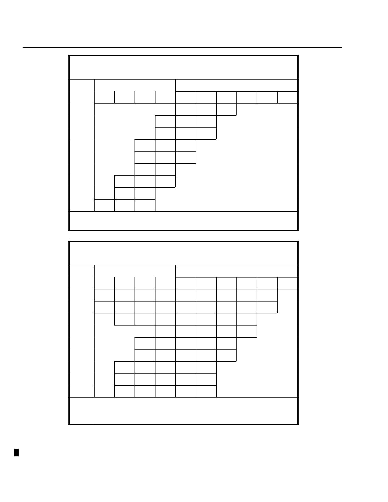
flated is limited. Refer to the appropriate VNE placards (Ref. Figure 9-7 and
Figure 9-8).
Environmental operating conditions:
Operating temperature range
Operational temperature range for over water-flight is:
-25°F (-31.7°C) minimum
+117°F (+47°C) maximum
Altitude limits - floats inflated
For water and ground landings, change of altitude is limited to 6500 feet
below the altitude at inflation or to 6500 feet below the maximum alti-
tude to which the inflated floats are subsequently flown. This assumes
the normal variation in ambient temperature associated with altitude
changes.
NOTE: If the allowable altitude change noted above is exceeded, the minimum
operational float pressure (2.0 psig) for water and ground landings may not be
available.
Air speed limits:
With floats stowed
With floats stowed, airspeed limitations are presented on the VNE IAS
(knots) FLOATS STOWED placards (Ref. Figure 9-7 and Figure 9-8).
For float inflation
Maximum speed for float inflation is 81 knots IAS at less than 6,000
feet altitude, 77 knots IAS at 6,000 feet altitude and above.
FAA Approved
9-26
Revision 14
MD 500E
ROTORCRAFT FLIGHT MANUAL
CSP-E-1
(Model 369E)
Optional Equipment
Emergency Floats
Gross weight limitations:
Maximum gross weight is 3000 pounds.
Minimum gross weight is 1680 pounds.
Center of gravity limits:
Longitudinal C.G. Limit
Lateral C.G. Limit
Gross Weight (lb)
(Sta-in.)
(Sta-in.)
Forward
Aft*
(-) Left, (+) Right
3000
99.0
103.0
± 3.0
2500
99.0
104.5
± 3.0
2000
99.0
106.0
± 3.0
1680
99.0
107.0
± 3.0
* NOTE: The aft longitudinal C. G. limit varies linearly from a gross weight of 3000
pounds at Station 103.0 to 1680 pounds at Station 107.0.
Placards:
When emergency floats are installed, the following placards are required:
WARNING: FLOAT INFLATION ABOVE 81 KNOTS IAS AT
Placard 1.
LESS THAN 6,000 FEET ALTITUDE, 77 KNOTS IAS AT
6,000 FEET AND ABOVE, IS PROHIBITED.
NIGHT FLIGHT OVER WATER BEYOND AUTOROTATION
Placard 2.
CAPABILITY TO GROUND IS PROHIBITED.
NOTE: Placard 2 not required if 369D292032 Night Landing Kit is installed.
VNE Placards
Refer to Figure 9-7 for helicopters equipped with Rolls Royce 250-C20B
engines.
Refer to Figure 9-8 for helicopters equipped with Rolls Royce
250-C20R/2 engines.
Be sure to select the appropriate VNE Placard for type of engine
CAUTIONinstalled in helicopter.
Kit compatibility:
The passenger step kit may not be installed in combination with emergency
floats.
FAA Approved
Revision 14
9-27
MD 500E
CSP-E-1
ROTORCRAFT FLIGHT MANUAL
(Model 369E)
Optional Equipment
Emergency Floats
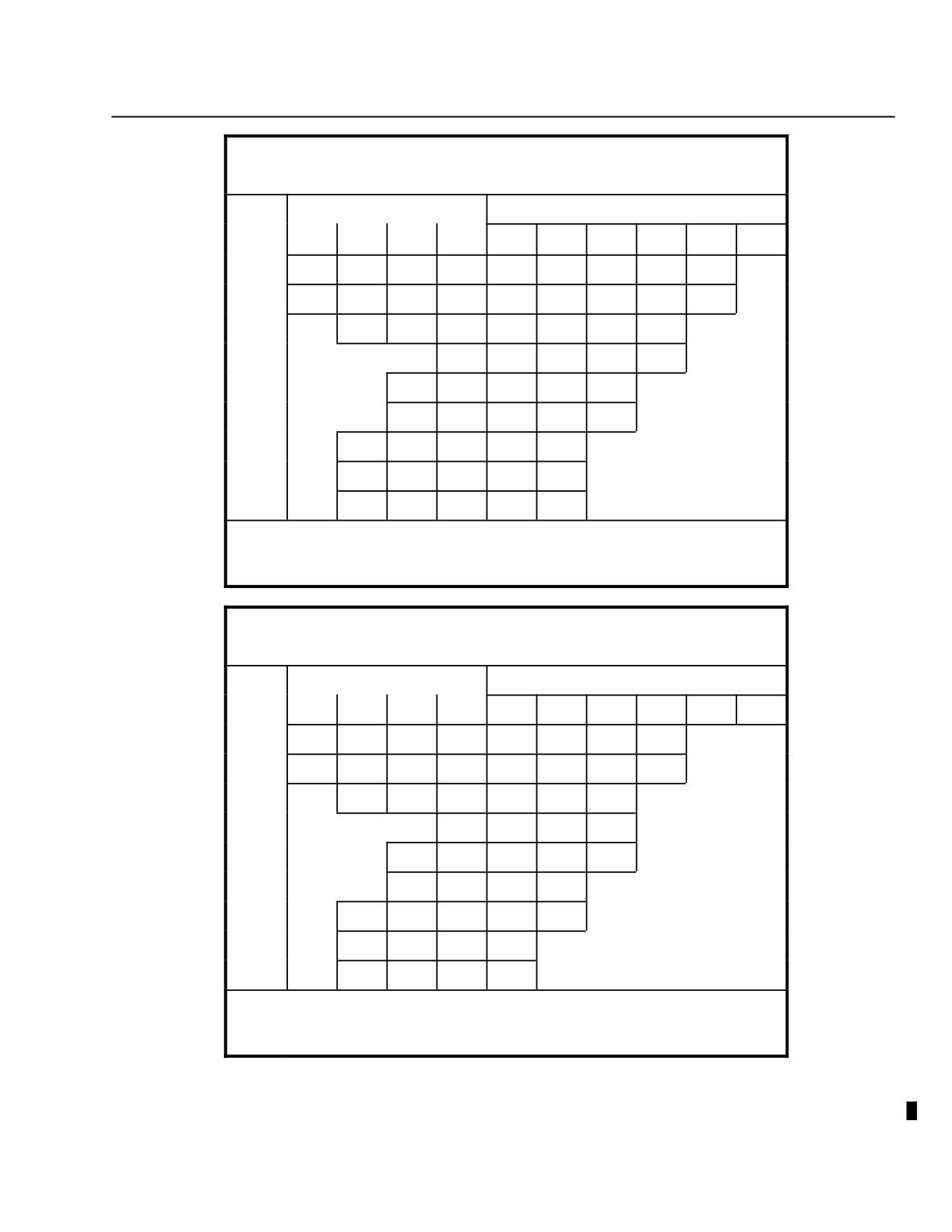
EMER FLOATS - INFLATED
VNE IAS (KNOTS)
OAT
PRESS ALT X 1000
GROSS WT = 1680 TO 3000 LB
°C
0
2
4
6
8
10
12
14
16
18
−30
98
91
77
−20
100
94
84
−10
101
97
91
77
0
100
94
85
10
97
91
78
NO FLIGHT
20
95
86
30
98
92
79
40
95
87
45
100
94
84
FOR AUTOROTATION VNE REDUCE SPEED BY 22K
(85K MIN); DO NOT EXCEED CHART VNE
FLOATS STOWED
VNE IAS (KNOTS)
OAT
PRESS ALT X 1000
GROSS WT = 1680 TO 2000 LB
°C
0
2
4
6
8
10
12
14
16
18
−30
141
136
131
127
122
118
113
109
104
−20
149
144
139
134
129
124
119
115
101
−10
151
145
140
135
130
125
110
0
146
141
136
121
102
10
152
151
148
144
138
111
20
150
146
143
123
104
30
151
148
145
141
114
NO FLIGHT
40
150
147
143
126
106
45
149
146
143
121
103
FOR AUTOROTATION VNE REDUCE SPEED BY 22K
(85K MIN); DO NOT EXCEED CHART VNE
MAX VNE 130KTS WITH LESS THAN 35 LB FUEL
Figure 9-7. VNE Placards - Rols Royce 250-C20B (Sheet 1 of 2)
FAA Approved
9-28
Revision 14
MD 500E
ROTORCRAFT FLIGHT MANUAL
CSP-E-1
(Model 369E)
Optional Equipment
Emergency Floats
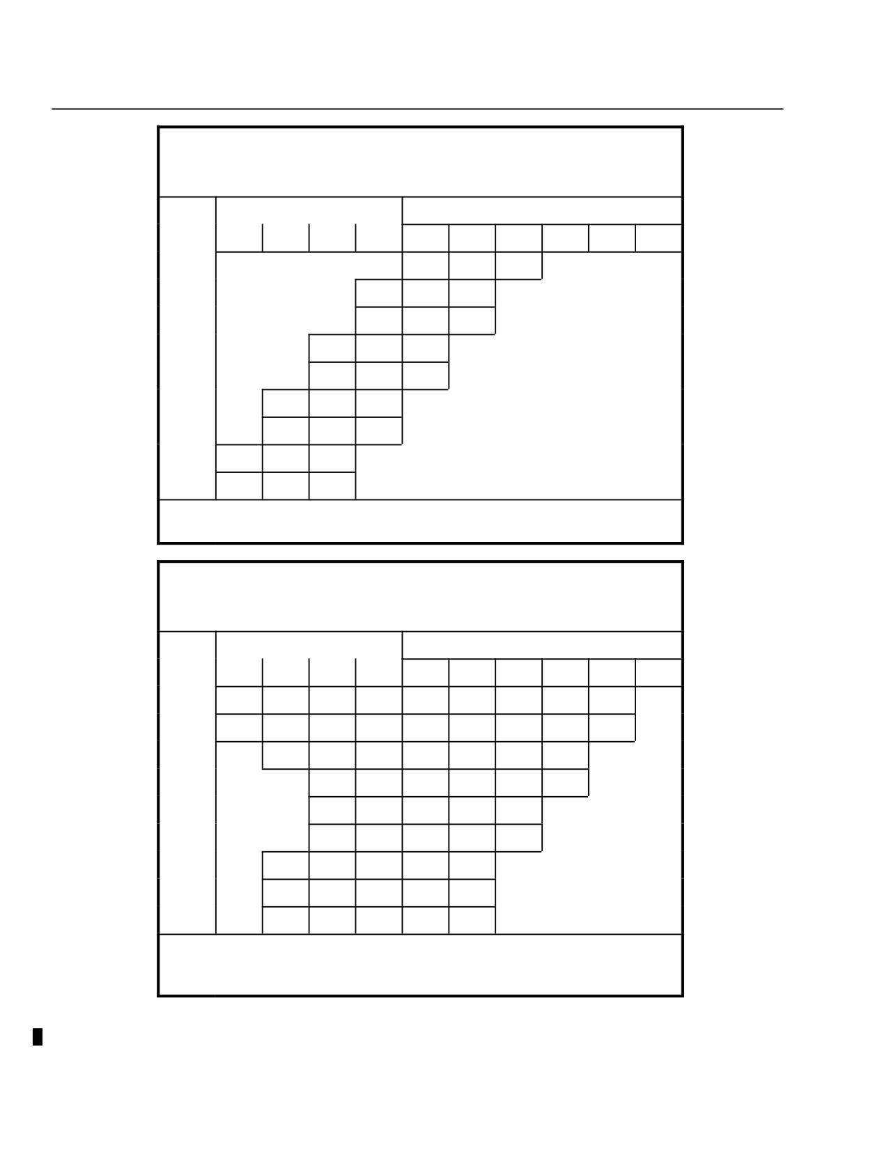
FLOATS STOWED
VNE IAS (KNOTS)
OAT
PRESS ALT X 1000
GROSS WT = 2001 TO 2500 LB
°C
0
2
4
6
8
10
12
14
16
18
−30
141
136
131
127
122
118
113
102
88
−20
149
144
139
134
129
124
110
94
82
−10
151
145
140
135
121
102
88
0
146
137
111
95
82
10
152
151
148
122
103
89
20
150
142
113
96
84
30
151
148
125
105
91
NO FLIGHT
40
150
147
115
98
86
45
149
135
111
95
83
FOR AUTOROTATION VNE REDUCE SPEED BY 22K
(90K MIN); DO NOT EXCEED CHART VNE
MAX VNE 130 KTS WITH LESS THAN 30 LB FUEL
FLOATS STOWED
VNE IAS (KNOTS)
OAT
PRESS ALT X 1000
GROSS WT = 2501 TO 3000 LB
°C
0
2
4
6
8
10
12
14
16
18
−30
141
136
131
127
122
114
97
83
−20
149
144
139
134
124
104
90
77
−10
151
145
138
114
97
83
0
124
105
90
78
10
152
139
114
98
84
72
20
125
106
92
79
30
143
116
99
86
74
NO FLIGHT
40
128
108
93
80
45
123
104
90
78
FOR AUTOROTATION VNE REDUCE SPEED BY 22K
(95K MIN); DO NOT EXCEED CHART VNE
MAX VNE 130 KTS WITH LESS THAN 30 LB FUEL
Figure 9-7. VNE Placards - Rolls Royce 250-C20B (Sheet 2 of 2)
FAA Approved
Revision 14
9-29
MD 500E
CSP-E-1
ROTORCRAFT FLIGHT MANUAL
(Model 369E)
Optional Equipment
Emergency Floats
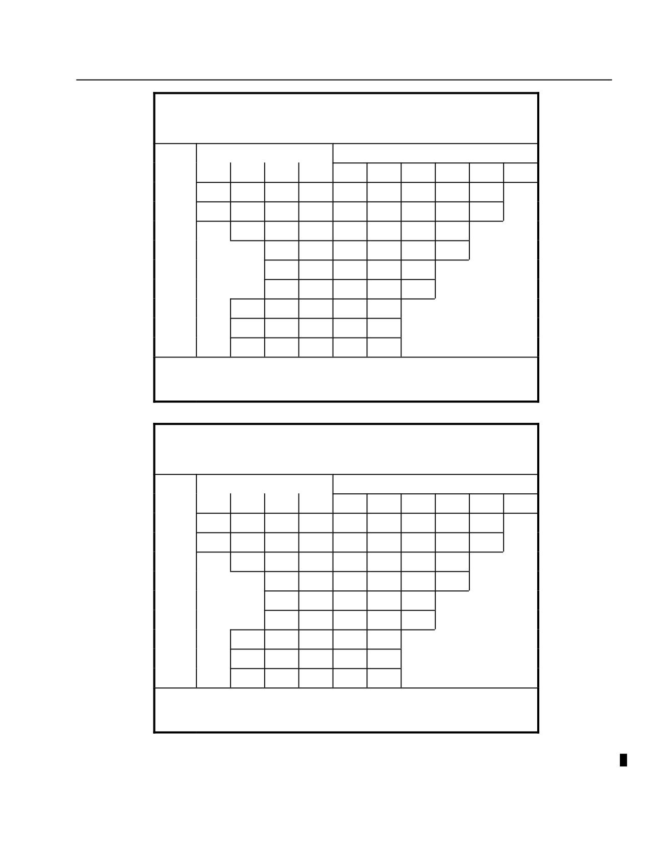
250 - C20R/2
EMER FLOATS - INFLATED
VNE IAS (KNOTS)
OAT
PRESS ALT X 1000
GROSS WT = 1680 TO 3000 LB
°C
0
2
4
6
8
10
12
14
16
18
−30
96
88
75
−20
98
92
82
−10
101
95
87
75
0
98
92
82
10
95
88
75
NO FLIGHT
20
99
92
83
30
96
89
77
40
99
93
84
45
98
92
82
FOR AUTOROTATION VNE REDUCE SPEED BY 22K
(90K MIN); DO NOT EXCEED CHART VNE
250 - C20R/2
FLOATS STOWED
VNE IAS (KNOTS)
OAT
PRESS ALT X 1000
GROSS WT = 1680 TO 2000 LB
°C
0
2
4
6
8
10
12
14
16
18
−30
141
136
131
126
122
117
113
108
104
−20
148
143
138
133
129
124
119
114
99
−10
150
145
140
135
130
125
108
0
151
146
141
135
118
100
10
152
150
147
144
132
109
20
149
145
142
120
102
30
154
147
144
138
111
NO FLIGHT
40
149
146
143
122
104
45
148
145
142
119
101
FOR AUTOROTATION VNE REDUCE SPEED BY 22K
(85K MIN); DO NOT EXCEED CHART VNE
MAX VNE 130 KTS WITH LESS THAN 35 LB FUEL
Figure 9-8. VNE Placards - Rolls Royce 250-C20R/2 (Sheet 1 of 2)
FAA Approved
9-30
Revision 14
MD 500E
ROTORCRAFT FLIGHT MANUAL
CSP-E-1
(Model 369E)
Optional Equipment
Emergency Floats
250 - C20R/2
FLOATS STOWED
VNE IAS (KNOTS)
OAT
PRESS ALT X 1000
GROSS WT = 2001 TO 2500 LB
°C
0
2
4
6
8
10
12
14
16
18
−30
141
136
131
126
122
117
112
96
82
−20
148
143
138
133
129
124
103
88
76
−10
152
145
140
135
112
96
82
0
151
146
125
104
89
77
10
152
150
147
113
97
83
20
147
128
105
90
78
30
150
147
115
99
84
NO FLIGHT
40
149
136
107
92
80
45
148
124
104
89
77
FOR AUTOROTATION VNE REDUCE SPEED BY 22K
(90K MIN); DO NOT EXCEED CHART VNE
MAX VNE 130 KTS WITH LESS THAN 30 LB FUEL
250 - C20R/2
FLOATS STOWED
VNE IAS (KNOTS)
OAT
PRESS ALT X 1000
GROSS WT = 2501 TO 3000 LB
°C
0
2
4
6
8
10
12
14
16
18
−30
141
136
131
126
122
110
91
77
66
−20
148
143
138
133
121
99
84
71
63
−10
150
145
136
109
91
77
66
0
151
121
100
84
71
63
10
152
136
110
92
78
67
20
122
101
85
72
64
30
139
112
93
79
68
NO FLIGHT
40
125
103
87
74
65
45
119
99
84
72
64
FOR AUTOROTATION VNE REDUCE SPEED BY 22K
(95K MIN); DO NOT EXCEED CHART VNE
MAX VNE 130 KTS WITH LESS THAN 30 LB FUEL
Figure 9-8. VNE Placards - Rolls Royce 250-C20R/2 (Sheet 2 of 2)
FAA Approved
Revision 14
9-31
MD 500E
CSP-E-1
ROTORCRAFT FLIGHT MANUAL
(Model 369E)
Optional Equipment
Emergency Floats
PART III
EMERGENCY AND
MALFUNCTION PROCEDURES
EMERGENCY FLOAT INFLATION
If emergency occurs at airspeeds greater than maximum
CAUTIONpermissible float inflation speed, i.e., 81 knots IAS at less than 6,000
feet altitude, 77 knots IAS at 6,000 feet altitude and above, reduce
speed to an appropriate value prior to float inflation. Do not exceed
airspeed limits of the EMERGENCY FLOATS INFLATED VNE placard.
NOTE: Inflations have been demonstrated up to 90 knots IAS in autorotation and in
powered flight.
Procedures:
F Check float circuit breaker IN.
F Actuate float inflation switch. (Only momentary switch actuation is re-
quired.)
F Inflation should be accomplished at 2,000 feet or less above landing sur-
face to minimize differential pressure change with altitude change.
F For over-water operation in conditions near the Height-Velocity Diagram,
immediate pilot reaction will be required to ensure float inflation prior to
water contact.
F Make a normal landing approach. Minimize forward speed prior to water
contact. Recommended water contact speed 10 knots or less. Do not lower
collective until forward speed is 5 knots or less. Landings have been dem-
onstrated at gross weights up to 3,000 pounds and touchdown speeds up
to approximately 10 knots.
F If emergency occurs at night over water, the dual landing lights should
not be illuminated above 1000 feet in order to preserve battery power. Ap-
proach and landing as noted above.
NOTE: Landings should be made with the helicopter as level as possible laterally and
the nose of the helicopter slightly high. One-float-first landings may produce
undesirable but controllable yaw.
FAA Approved
9-32
Revision 14
MD 500E
ROTORCRAFT FLIGHT MANUAL
CSP-E-1
(Model 369E)
Optional Equipment
Emergency Floats
PART IV
NORMAL PROCEDURES
Preflight checks:
Check condition and security of stowed float package.
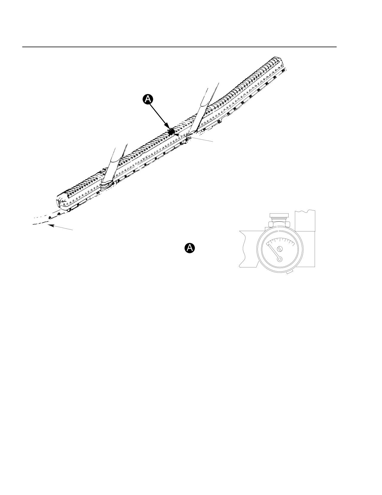
Check pressure gauge in each float package. If the pressure vessel is at
70°F (21.1°C), the pressure should read within 3000 to 3500 psig (Ref.
Figure 9-9).
Indicated gauge pressure will increase (decrease) approximately, as tabu-
lated below, per 1°F (1°C) increase (decrease) in temperature of the pressure
vessel.
Charge
Psig °F
Psig °C
Pressure
3000
5.7
10.2
3100
5.9
10.5
3500
6.6
11.9
Set BAT-EXT switch in proper position (BAT when using rotorcraft battery.
EXT when using an external power source.)
Check FLOATS circuit breaker IN.
FLOAT
P TEST
LH/RH
Press to test green float
indicator. LH and RH indicator lamps
should illuminate indicating that each circuit is operational.
Landing:
Tail-low landings on hard surfaces should be avoided, as stress
CAUTIONdamage to the float extensions may occur.
In-flight float inflation data:
Float inflation time and altitude required for deployment are presented be-
low. Time is affected by temperature. Deployment altitude is based on a sta-
bilized autorotational rate of descent of 1800 feet per minute. It was calcu-
lated using the tabulated float inflation time, and a two second increment
for pilot reaction time:
Float Inflation Time
9.0 sec Temps up to 21°C
6.3 sec Temps above 21°C
Altitude Required For Deployment
330 feet Temps up to 21°C
250 feet Temps up to 21°C
FAA Approved
Revision 14
9-33
MD 500E
CSP-E-1
ROTORCRAFT FLIGHT MANUAL
(Model 369E)
Optional Equipment
Emergency Floats
PRESSURE GAGE
INSPECTION WINDOW
RIGHT HAND SKID (LEFT HAND SIMILAR)
PRESSURE GAGE
F03
Figure 9-9. Float Pressure Gauge
PART V
PERFORMANCE DATA
Hover Performance with Stowed Floats
No change from that of the basic helicopter with extended landing gear.
PART VII
HANDLING SERVICING
AND MAINTENANCE
Inspection and functional checks of the emergency float system should be con-
ducted in accordance with applicable installation instructions.
FAA Approved
9-34
Revision 14
MD 500E
ROTORCRAFT FLIGHT MANUAL
CSP-E-1
(Model 369E)
Optional Equipment
Engine Air Inlet Diverter
9-9. OPERATING INSTRUCTIONS - ENGINE AIR INLET DIVERTER
PART I
GENERAL
The MDHI Engine Air Inlet Diverter Kit (either 1 or 2 piece) inhibits ingesting
foreign objects into the engine air inlet which might be of sufficient mass to
puncture the inlet screen/particle separator and damage the engine. It reduces
ingestion of large dust and sand particles. It also reduces ingestion of snow and
slush, which may accumulate on the canopy at very slow speeds to be subse-
quently swept toward the inlet when forward speed is increased. The kit in-
cludes a hub and engine air inlet cover to prevent the entrance of snow and
water when the helicopter is parked.
FAA Approved
Revision 14
9-35
MD 500E
CSP-E-1
ROTORCRAFT FLIGHT MANUAL
(Model 369E)
Optional Equipment
Engine Air Inlet Diverter
PART II
LIMITATIONS
Environmental operating conditions:
Maximum operating OAT is 28°C at sea level, with 2.0°C per 1000 feet
lapse rate.
Airspeed limits:
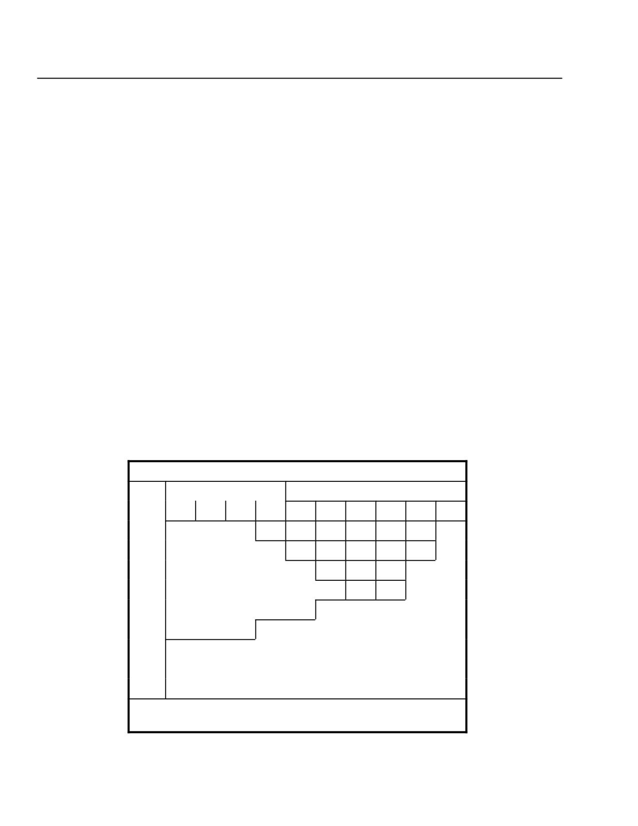
VNE is limited to 122 knots IAS or less (Ref. Figure 9-10).
VNE is limited to 99 knots IAS or less during autorotation (Ref.
Figure 9-10).
Kit Compatibility:
The Mist Eliminator, 369D290125-21, may not be used with the Engine Air
Inlet Diverter Kit.
The Inlet Diverter Kit is not approved for use with the Allison 250-C20R/2
engine.
Placards:
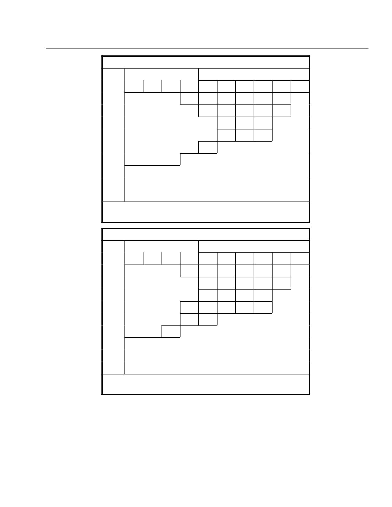
Refer to Figure 9-10 for VNE limitations.
VNE IAS (KTS) INLET DIVERTER
OAT
PRESS ALT X 1000
GROSS WT = 2000 LB OR LESS
°C
0
2
4
6
8
10
12
14
16
18
−30
117
112
109
104
99
96
−20
119
114
110
105
92
−10
121
116
100
0
122
111
93
10
20
30
NO FLIGHT
40
45
FOR AUTOROTATION VNE REDUCE SPEED BY 23K
(85K MIN); DO NOT EXCEED CHART VNE
Figure 9-10. VNE Placards (Sheet 1 of 2)
FAA Approved
9-36
Revision 14
MD 500E
ROTORCRAFT FLIGHT MANUAL
CSP-E-1
(Model 369E)
Optional Equipment
Engine Air Inlet Diverter
VNE IAS (KTS) INLET DIVERTER
OAT
PRESS ALT X 1000
GROSS WT = 2001 TO 2500 LB
°C
0
2
4
6
8
10
12
14
16
18
−30
117
113
109
104
95
81
−20
119
114
103
87
75
−10
114
95
81
0
122
95
88
76
10
115
20
30
NO FLIGHT
40
45
FOR AUTOROTATION VNE REDUCE SPEED BY 23K
(90K MIN); DO NOT EXCEED CHART VNE
VNE IAS (KTS) INLET DIVERTER
OAT
PRESS ALT X 1000
GROSS WT = 2501 TO 3000 LB
°C
0
2
4
6
8
10
12
14
16
18
−30
117
113
106
91
76
63
−20
116
97
84
70
58
−10
122
106
90
76
64
0
116
97
84
70
59
10
106
91
20
118
30
NO FLIGHT
40
45
FOR AUTOROTATION VNE REDUCE SPEED BY 23K
(95K MIN); DO NOT EXCEED CHART VNE
Figure 9-10. VNE Placards (Sheet 2 of 2)
FAA Approved
Revision 14
9-37
MD 500E
CSP-E-1
ROTORCRAFT FLIGHT MANUAL
(Model 369E)
Optional Equipment
Engine Air Inlet Diverter
PART III
EMERGENCY AND
MALFUNCTION PROCEDURES
AIR RESTART - ENGINE
Procedures:
F Follow the emergency air restart procedure described in Section III.
F Recommended pressure altitude is 11,000 feet or below.
PART IV
NORMAL PROCEDURES
Cruise:
If at high cruise speed engine oil temperature approaches its limit, it may
be reduced by reducing airspeed.
FAA Approved
9-38
Revision 14
MD 500E
ROTORCRAFT FLIGHT MANUAL
CSP-E-1
(Model 369E)
Optional Equipment
Utiltiy Floats
9-10. OPERATING INSTRUCTIONS - UTILITY FLOATS
PART I
GENERAL
The MDHI Utility Float Kit is designed to facilitate operation of the helicopter
from both land and water. The kit consists of two multicell bag type floats, two
aft skid tube extensions, two sets of stabilizing surfaces, and the necessary
hardware for attachment. The floats mount on Extended Landing Gear.
An optional Night Landing Lighting Kit is available consisting of dual belly
mounted sealed beam lights, a circuit breaker, and a three position switch
installed on the collective control. Forward position illuminates the standard
nose mounted landing light; center position is off; and aft position illuminates
the belly lights. Night flight over water is permitted with the night landing
lighting kit installed.
FAA Approved
Revision 14
9-39
CSP-E-1
ROTORCRAFT FLIGHT MANUAL
MD 500E
(Model 369E)
Optional Equipment
Utiltiy Floats
PART II
LIMITATIONS
Float inflation pressure:
Minimum float operational pressure is 2.0 psig.
Types of operation:
Night flight over water beyond autorotation capability to ground is prohib-
ited, unless Night Landing Lighting Kit is installed .
Takeoff and landing on water at night is prohibited, unless Night Landing
Lighting Kit is installed.
Environmental operating conditions:
Changes of altitude are limited in accordance with the following.
The water landing site altitude may be at any altitude equal to or higher
than the takeoff base altitude, provided that the descent from the peak
altitude flown does not exceed 7700 feet.
NOTE: Each float cell has a pressure relief valve nominal setting of 5 psig. If the above
noted allowable decrease in altitude is exceeded, minimum operational float
pressure (2.0 psig) may not be available should the relief valve function at its
lower tolerance limit. This assumes the increase in temperature with decrease
in altitude is the standard lapse rate, i.e., (+) 3.6°F per (-) 1000 feet.
For takeoff from a high altitude base with the water landing site at a
lower altitude:
If the float pressure
The allowable altitude
(psig) at takeoff is:
decrease (feet) is:
2.0
0
2.5
1300
3. 0
2700
3.5
4300
4.0
5900
4.5
7700
5.0
9500
FAA Approved
9-40
Revision 14
MD 500E
ROTORCRAFT FLIGHT MANUAL
CSP-E-1
(Model 369E)
Optional Equipment
Utiltiy Floats
NOTE: To account for anticipated variations in ambient temperature or water
temperature at a scheduled landing site, the following procedure should be used
to maintain the minimum 2. 0 psig inflation pressure.
For ambient (air) temperature or water temperature colder than the temperature
at initial inflation, float inflation pressure should be increased 0.5 psig (above) the
minimum 2.0 psig) for each 15°F decrease in temperature anticipated.
Example:
70°F Ambient temperature at time of inflation minus
45°F Anticipated water temperature at scheduled landing sited equals
25°F Temperature decrease
Inflation pressure change to account for temperature change
(25° B 15°) x 0.5 psig = 0.8 psig
Minimum float inflation pressure for this operation would be
2.0 psig + 0.8 psig = 2.8 psig
NOTE: Temperature increase will increase float inflation pressure and need not be
considered.
Center of gravity (C.G. Envelope):
NOTE: The installation of the float kit contributes to an aft shift of the C.G. For conditions
requiring pilot only operations, ballast will be required in the utility stowage
compartment or front seat. The operator should determine the proper amount of
ballast required to remain within the aft C. G. limit for the zero fuel condition .
Placards:
Placards 1, and 2, are required when the utility floats are installed.
PLACARD #1 NIGHT FLIGHT OVER WATER BEYOND
AUTOROTATION CAPABILITY TO
GROUND PROHIBITED.
PLACARD #2 MINIMUM FLOAT PRESSURE 2.0 PSIG.
NOTE: Placard 1 not required if 369D292032 Night Landing Lighting Kit is installed.
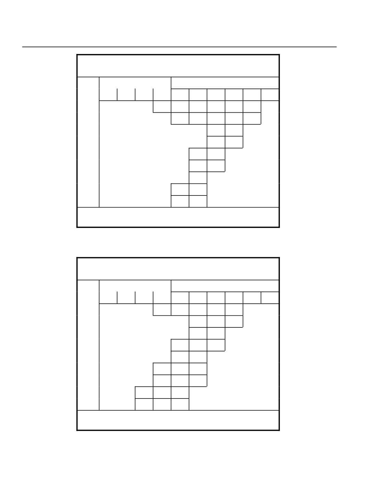
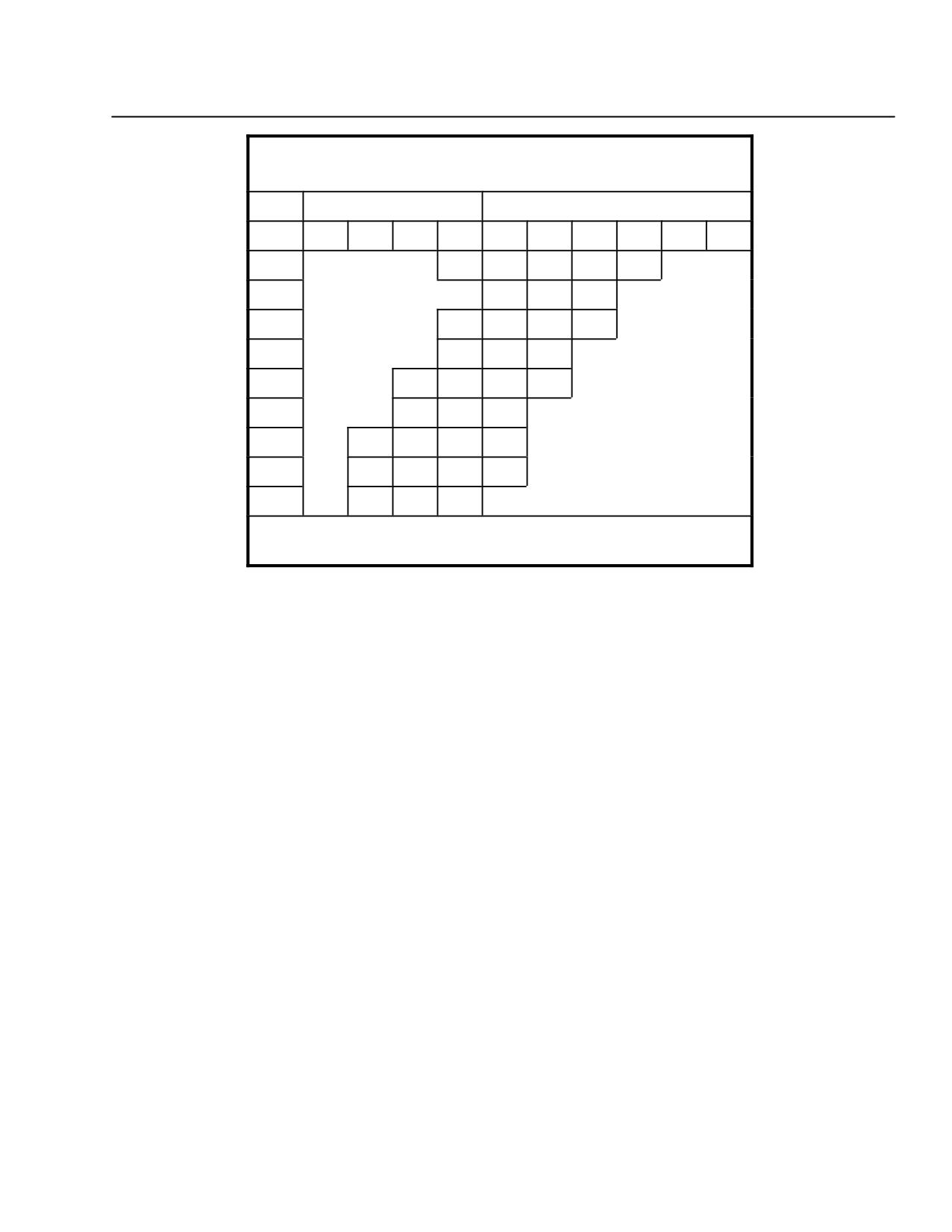
Refer to Figure 9-11 for VNE placards with utility floats installed.
FAA Approved
Revision 14
9-41
CSP-E-1
ROTORCRAFT FLIGHT MANUAL
MD 500E
(Model 369E)
Optional Equipment
Utiltiy Floats
UTILITY FLOATS
VNE IAS (KNOTS)
OAT
PRESS ALT X 1000
GROSS WT = 2000 OR LESS
°C
0
2
4
6
8
10
12
14
16
18
−30
127
122
118
113
109
100
−20
129
124
119
109
91
−10
122
100
0
130
110
92
10
124
101
20
112
94
30
103
NO FLIGHT
40
115
91
45
110
93
FOR AUTOROTATION VNE REDUCE SPEED BY 2K
(85K MIN); DO NOT EXCEED CHART VNE
UTILITY FLOATS
VNE IAS (KNOTS)
OAT
PRESS ALT X 1000
GROSS WT = 2001 TO 2500
°C
0
2
4
6
8
10
12
14
16
18
−30
127
122
118
110
94
−20
121
102
86
−10
110
94
0
130
121
102
87
10
111
94
20
123
103
88
30
112
96
83
NO FLIGHT
40
125
105
90
45
120
102
87
FOR AUTOROTATION VNE REDUCE SPEED BY 2K
(90K MIN); DO NOT EXCEED CHART VNE
Figure 9-11. VNE Placards (Sheet 1 of 2)
FAA Approved
9-42
Revision 14
MD 500E
ROTORCRAFT FLIGHT MANUAL
CSP-E-1
(Model 369E)
Optional Equipment
Utiltiy Floats
UTILITY FLOATS
VNE IAS (KNOTS)
OAT
PRESS ALT X 1000
GROSS WT = 2501 T0 3000
°C
0
2
4
6
8
10
12
14
16
18
−30
127
122
107
93
79
−20
116
100
86
−10
126
107
93
79
0
130
116
100
87
10
126
108
94
80
20
117
101
87
30
128
109
94
82
NO FLIGHT
40
118
102
89
76
45
115
99
87
FOR AUTOROTATION VNE REDUCE SPEED BY 2K
(95K MIN); DO NOT EXCEED CHART VNE
Figure 9-11. VNE Placards (Sheet 2 of 2)
Kit combination limitations:
The Passenger Step Kit 369H90060 may not be installed in combination
with utility floats.
The Cargo Hook Kit may be used in combination with the utility floats.
With an external load on the hook, the VNE limitations of the Cargo Hook
Kit apply (Ref. Figure 9-1). The external load on the hook is limited to 1865
lbs maximum.
Litter Kits may not be used in combination with the utility floats.
The Four-Bladed Tail Rotor Kit may not be used in combination with the
utility floats.
FAA Approved
Revision 14
9-43
CSP-E-1
ROTORCRAFT FLIGHT MANUAL
MD 500E
(Model 369E)
Optional Equipment
Utiltiy Floats
PART III
EMERGENCY AND
MALFUNCTION PROCEDURES
AUTOROTATIONAL LANDING
Procedures:
F Make a normal autorotational approach. Minimize forward speed prior to
water contact.
F Recommended water contact speed 10 knots or less. Do not lower collec-
tive until forward speed is 5 knots or less.
F Landings have been demonstrated at gross weights up to 3000 pounds and
touchdown speeds up to approximately 15 knots.
NOTE: Landings should be made with the helicopter as level as possible laterally and
the nose of the helicopter slightly high. One-float-first landings may produce
undesirable but controllable yaw.
If emergency occurs at night over water, the dual landing lights should not be
illuminated above 1000 feet altitude in order to preserve battery power.
PART IV
NORMAL PROCEDURES
Rotor engagement on water:
Determine that sufficient clearance exists between the helicopter and any
obstacle during engine start. Tail swing, before directional control is ob-
tained, will be approximately 200 degrees.
Landing:
Make a normal landing approach. Minimize forward speed prior to water
contact. Recommended water contact speed 10 knots or less. Do not lower
collective until forward speed is 5 knots or less. Landings have been demon-
strated at gross weights up to 3000 pounds and touchdown speeds up to
approximately 15 knots.
NOTE: Landings should be made with the helicopter as level as possible laterally and
the nose of the helicopter slightly high. One-float-first landings may produce
undesirable but controllable yaw.
FAA Approved
9-44
Revision 14
MD 500E
ROTORCRAFT FLIGHT MANUAL
CSP-E-1
(Model 369E)
Optional Equipment
Utiltiy Floats
Water taxiing:
Water taxi speed should be less than 10 knots. It will be necessary to use
some collective pitch to taxi at greater than 5 knots.
Some collective pitch may be required under certain conditions to stop heli-
copter during water taxi. The use of aft longitudinal cyclic is not completely
effective under all conditions.
Rotor brake application on water:
Determine that sufficient clearance exists between the helicopter and any
obstacle during rotor brake application. Azimuth change will be approxi-
mately 200° (nose left).
PART V
PERFORMANCE DATA
Hover performance:
Refer to Section V for IGE hover performance data.
Height-Velocity diagram:
Refer to Figure 9-12.
Airspeed calibration:
Refer to Figure 9-13.
FAA Approved
Revision 14
9-45
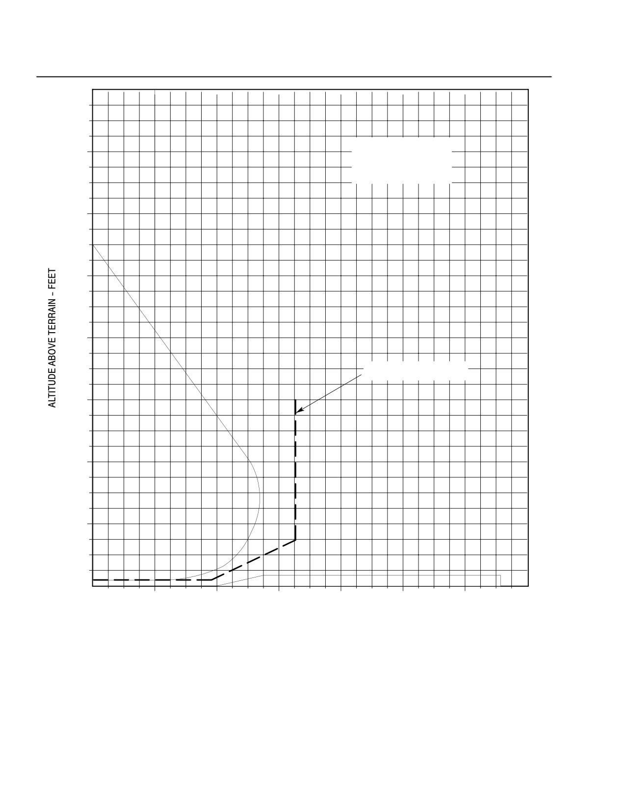
CSP-E-1
ROTORCRAFT FLIGHT MANUAL
MD 500E
(Model 369E)
Optional Equipment
Utiltiy Floats
SMOOTH HARD SURFACE
OR CALM WATER
WIND CALM
AVOID OPERATION IN
CROSS-HATCHED AREAS
600
500
Î
Î
Î
Î
Î
Î
Î
Î
Î
Î
Î
400
Î
Î
Î
Î
Î
Î
Î
Î
Î
Î
RECOMMENDED TAKEOFF
Î
Î
Î
Î
Î
PROFILE
Î
Î
Î
Î
Î
Î
300
Î
Î
Î
Î
Î
Î
Î
Î
Î
Î
Î
Î
Î
Î
Î
Î
Î
Î
Î
Î
Î
Î
Î
Î
Î
Î
Î
Î
Î
Î
Î
Î
Î
Î
200
Î
Î
Î
Î
Î
Î
Î
Î
Î
Î
Î
Î
Î
Î
Î
Î
Î
Î
Î
Î
Î
Î
Î
Î
Î
Î
Î
Î
Î
Î
Î
Î
Î
Î
Î
Î
Î
Î
Î
Î
Î
Î
100
Î
Î
Î
Î
Î
Î
Î
Î
Î
Î
Î
Î
Î
Î
Î
Î
Î
Î
Î
Î
Î
Î
Î
Î
Î
Î
Î
Î
Î
Î
Î
Î
Î
Î
Î
Î
Î
Î
Î
Î
Î
Î
Î
Î
Î
Î
Î
Î
Î
Î
Î
Î
Î
0
ÎÎ
ÎÎÎÎ
ÎÎÎÎ
ÎÎÎÎ
ÎÎ
0
20
40
60
80
100
120
140
INDICATED AIRSPEED - KNOTS
F03-046
(CORRECTED FOR INSTRUMENT ERROR)
Figure 9-12. Height-Velocity Diagram - Utility Floats Installed
FAA Approved
9-46
Revision 14
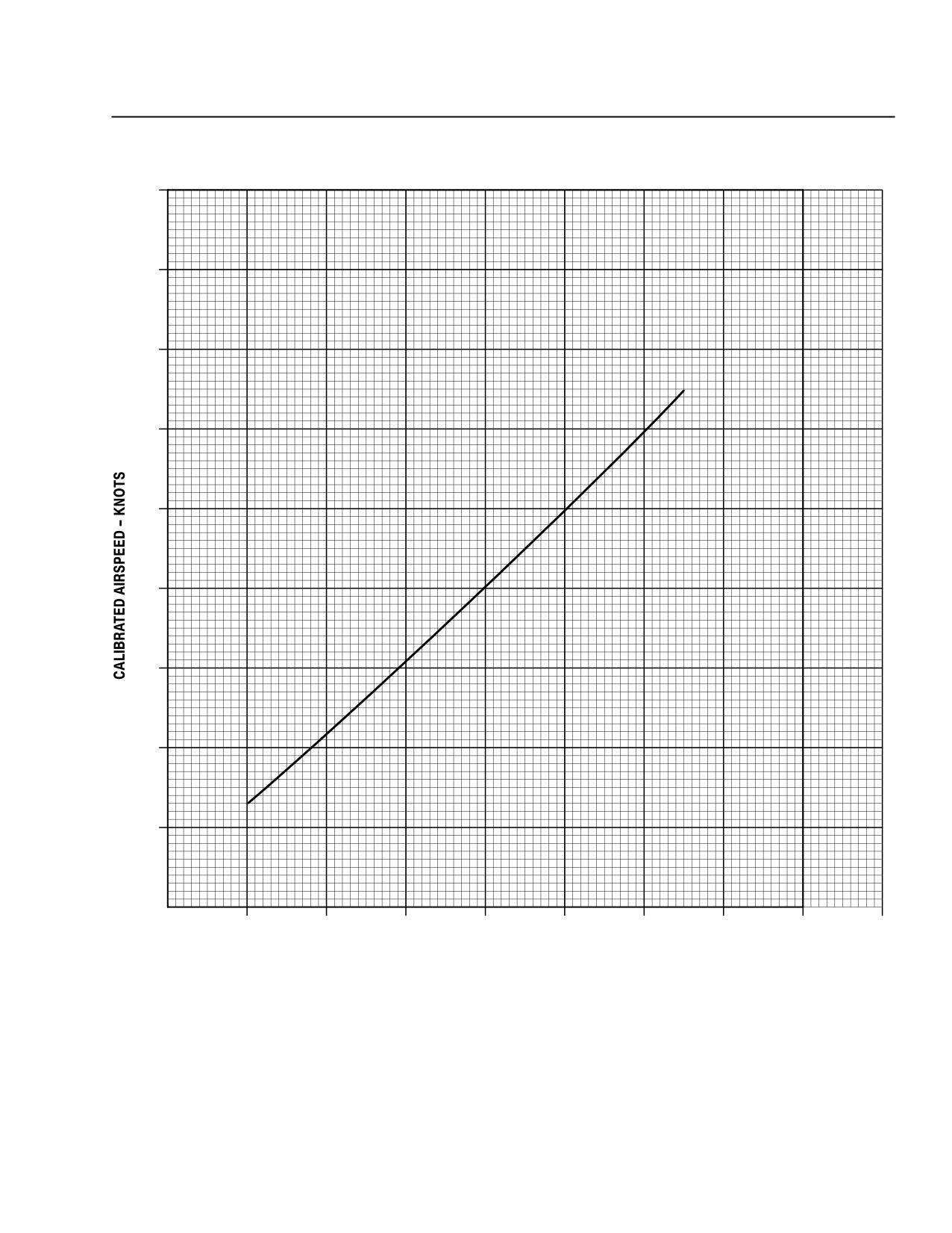
MD 500E
ROTORCRAFT FLIGHT MANUAL
CSP-E-1
(Model 369E)
Optional Equipment
Utiltiy Floats
180
160
140
120
100
80
60
40
20
0
20
40
60
80
100
120
140
160
180
INDICATED AIRSPEED - KNOTS
(CORRECTED FOR INSTRUMENT ERROR)
F03-047
Figure 9-13. Airspeed Calibration Curve - Utility Floats Installed
FAA Approved
Revision 14
9-47
CSP-E-1
ROTORCRAFT FLIGHT MANUAL
MD 500E
(Model 369E)
Optional Equipment
Utiltiy Floats
PART VII
HANDLING SERVICING
AND MAINTENANCE
Inspection and functional checks of the utility float system should be conducted
in accordance with applicable installation instructions.
PART VIII
ADDITIONAL OPERATIONS
AND PERFORMANCE DATA
Refer to Section VIII for OGE hover performance charts.
FAA Approved
9-48
Revision 14
MD 500E
ROTORCRAFT FLIGHT MANUAL
CSP-E-1
(Model 369E)
Optional Equipment
Garmin G500H Integrated System
9-11. OPERATING INSTRUCTIONS: GARMIN G500H INTEGRATED
SYSTEM
PART I
GENERAL
Information for operating the Garmin Avionics Suite is contained with the fol-
lowing supplied vendor documents.
G500H Cockpit Reference Guide - 190-01150-03 Rev B, or later
G500H Pilot's Guide - 190-01150-02 Rev B, or later
GMA 347 Audio Panel Pilot Guide
GNS 430W Pilot Guide and Reference
GNC 420W Pilot Guide and Reference
GTX 330 Transponder Pilot Guide
Major components:
GDU 620 Dual Display (PDF/MFD)
GNS 430W all-in-one GPS/NAV/COM
GNC 420W GPS/COM
GMA 347 Audio Panel
GTX 330 Mode S Transponder
GDC 74H Air Data Computer (ADC)
GTP 59 OAT Probe
GRS 77H Attitude and Heading Reference System (AHRS)
GMU 44 Magnetometer
Other integrated equipment:
Emergency Locator Transmitter - 406MHz
Avionics Cooling Fan
Avionics Master Switch
Collective Hobbs Hour Meter
PART II
LIMITATIONS
NOTE: Flight operations with the Garmin Suite requires compliance with Section II,
Paragraph 2-2, “Kinds of Operations”, specifically “for day and night VFR
operations only”.
FAA Approved
Revision 18
9-49
CSP-E-1
ROTORCRAFT FLIGHT MANUAL
MD 500E
(Model 369E)
Optional Equipment
Garmin G500H Integrated System
PART III
EMERGENCY AND
MALFUNCTION PROCEDURES
GENERAL
NOTE: GDU 620 PFD airspeed tape may lag during aggressive acceleration or
deceleration.
AVIONICS POWER FAILURE
Indications: Loss of avionics equipment on AVIONICS BUS and avionics master circuit
breaker switch
not in UP position.
Conditions: Power failure to Avionics Bus
NOTE: Only the GNS 430, PFD, MFD and audio panel remain functional.
Procedures:
F Cycle avionics master switch back to ON.
F If condition remains, ensure avionics master switch remains OFF.
F Continue flight using remaining avionics, and advise maintenance after
landing.
PART IV
NORMAL PROCEDURES
No change for start or shutdown procedures found in Section IV except:
Daily Preflight Checks - Exterior Fuselage - Forward End
F
OAT Probe
CHECK: SECURED /
NO DAMAGE
Pre-start cockpit check - Electrical Power ON
F
G500H PFD and MFD
CHECK ON
F
Basic pre-start checks
COMPLETE
F
G500H PFD and MFD
CHECK FOR ALERT
INDICATIONS
DURING START-UP
FAA Approved
9-50
Revision 18
MD 500E
ROTORCRAFT FLIGHT MANUAL
CSP-E-1
(Model 369E)
Optional Equipment
Garmin G500H Integrated System
Engine run-up:
F
Basic start procedures
COMPLETE
F
Avionics master switch
ON
F
GNS 430
ON / CHECK
DATABASE
CURRENT
F
Press ENTER on GNS 430 /
CHECK INSTRUMENT
select GPS 1 on PFD
PANEL SELF-TEST
ON PFD
F
GNC 420
ON / CHECK
DATABASE
CURRENT
F
Press ENTER on GNC 420 /
CHECK INSTRUMENT
select GPS 2 on PFD
PANEL SELF-TEST
ON PFD
FAA Approved
Revision 18
9-51
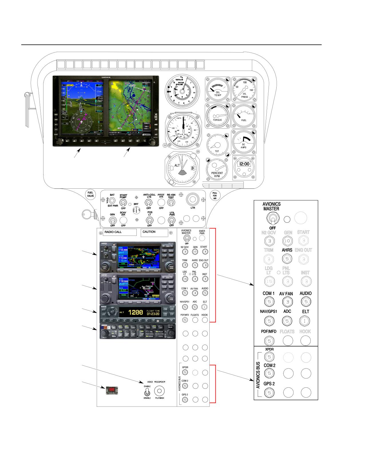
CSP-E-1
ROTORCRAFT FLIGHT MANUAL
MD 500E
(Model 369E)
Optional Equipment
Garmin G500H Integrated System
PFD
MFD
GNS 430W
GNC 420W
GTX 330
GMA 347
VOICE RECORDER
ELT
F03-058
Figure 9-14. Instrument Panel, LH Command - Layout Typical
FAA Approved
9-52
Revision 18
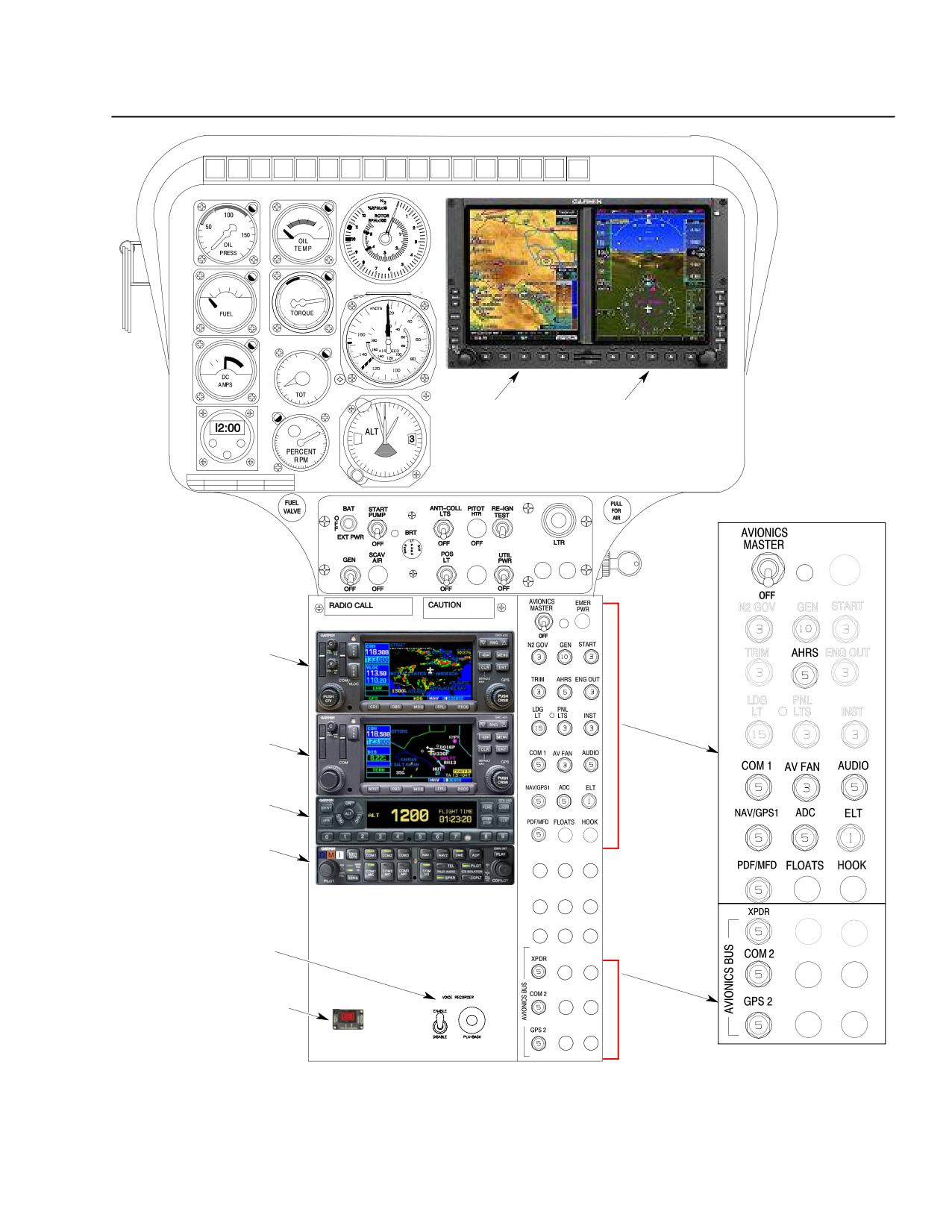
MD 500E
ROTORCRAFT FLIGHT MANUAL
CSP-E-1
(Model 369E)
Optional Equipment
Garmin G500H Integrated System
MFD
PFD
GNS 430W
GNC 420W
GTX 330
GMA 347
VOICE RECORDER
ELT
F03-057
Figure 9-15. Instrument Panel, RH Command - Layout Typical
FAA Approved
Revision 18
9-53
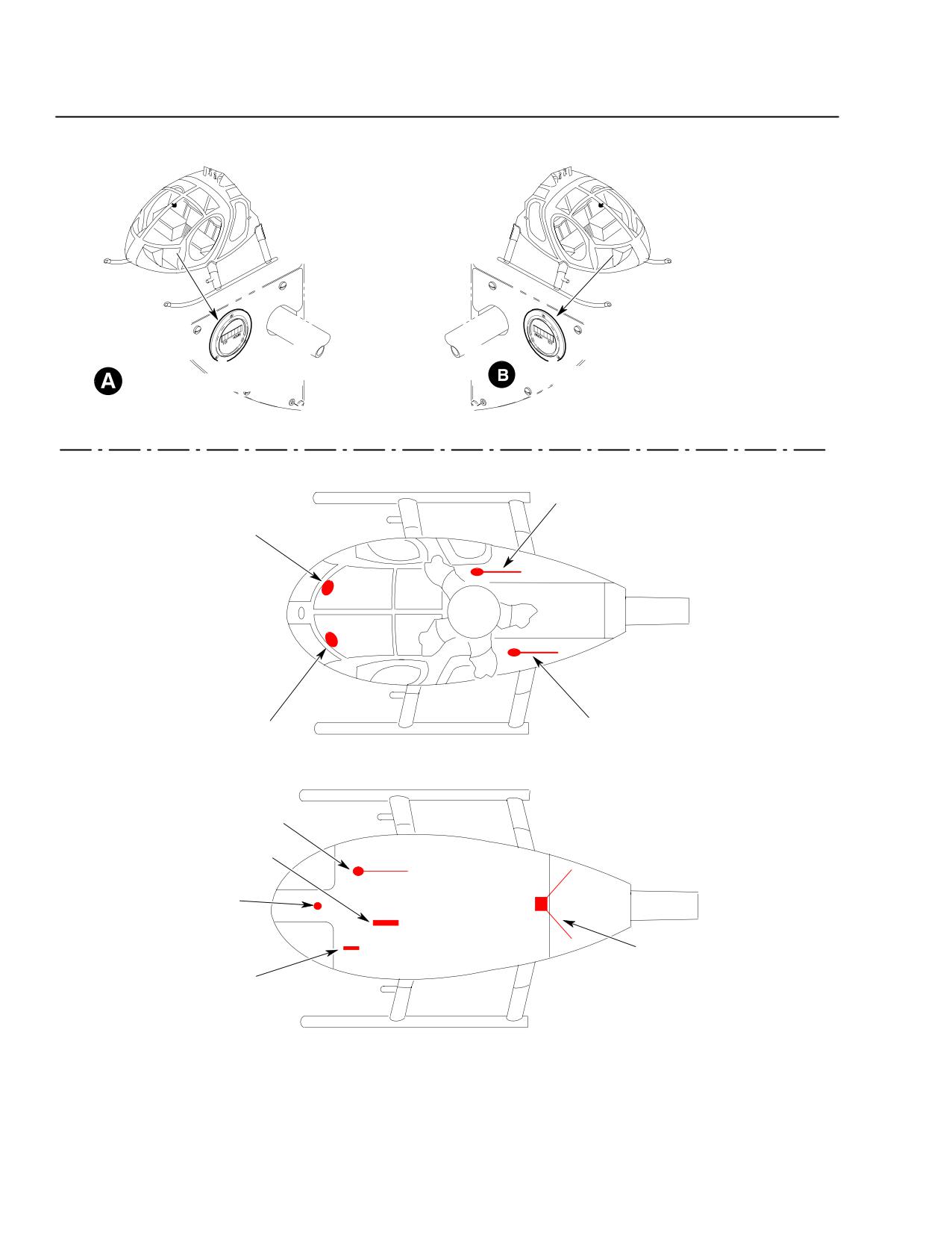
CSP-E-1
ROTORCRAFT FLIGHT MANUAL
MD 500E
(Model 369E)
Optional Equipment
Garmin G500H Integrated System
COLLECTIVE HOBBS METER
AIRFRAME HOBBS METER
NOTE: COLLECTIVE HOBBS METER TRACKS TIME ONCE
THE COLLECTIVE IS RAISED OFF THE STOP
COM 2
GPS2 (IF INSTALLED)
ELT
GPS1
TOP VIEW
COM 1
MARKER BEACON
OAT PROBE
NAV
TRANSPONDER
BOTTOM VIEW
F03-056
Figure 9-16. Runtime (Hobbs) Meter, OAT Probe and NAV/COM Antenna Locations -
Typical
FAA Approved
9-54
Revision 18
MD 500E
ROTORCRAFT FLIGHT MANUAL
CSP-E-1
(Model 369E)
Optional Equipment
Garmin G500H Integrated System
PART V
PERFORMANCE DATA
No change.
PART VI
WEIGHT AND BALANCE DATA
No change.
PART VII
HANDLING SERVICING
AND MAINTENANCE
No change.
PART VIII
ADDITIONAL OPERATIONS
AND PERFORMANCE DATA
No change.
FAA Approved
Revision 18
9-55