Helicopter MD 500E. Flight Manual (1982-2011) - page 1
MD 500E
Flight Manual
THIS IS A COMPLETE REPRINT OF CSP-E-1
AND IS CURRENT THROUGH REISSUE #1, REVISION 18
CSP-E-1
R
MD 500E
Title Page
FAA APPROVED
ROTORCRAFT
FLIGHT MANUAL
Type Certificate No. H3WE
Approved By_____________________________________
Manager, Flight Test Branch, ANM-160L
Federal Aviation Administration
Los Angeles Aircraft Certification Office
Transport Airplane Directorate
Original Approval Date:
23 November 1982
Reissue #1:
_______________________________________
THE FAA APPROVED ROTORCRAFT FLIGHT MANUAL CONSISTS OF THE FOLLOWING SECTIONS.
SECTION II -
LIMITATIONS
SECTION III -
EMERGENCY PROCEDURES
SECTION IV -
NORMAL PROCEDURES
SECTION V -
PERFORMANCE DATA
SECTION IX
OPTIONAL EQUIPMENT
THE HELICOPTER MUST BE OPERATED IN COMPLIANCE WITH THE OPERATING LIMITATIONS AS SET FORTH IN SECTION II OF THIS MANUAL AND
ANY ADDITIONAL LIMITATIONS FROM SECTION IX AS A RESULT OF AN INSTALLED OPTIONAL EQUIPMENT ITEM.
SECTIONS III, IV, AND V CONTAIN RECOMMENDED PROCEDURES AND DATA AND ARE FAA APPROVED.
THE ``AIRWORTHINESS LIMITATIONS'' LISTED IN SECTION 04-00-00 OF CSP-HMI-2 SHALL BE COMPLIED WITH.
THIS MANUAL MUST BE KEPT IN THE HELICOPTER AT ALL TIMES.
All rights reserved under the copyright laws.
Revision 13
F-i
CSP-E-1
ROTORCRAFT FLIGHT MANUAL
MD 500E
(Model 369E)
LOG OF REVISIONS BY DATE
FAA / NON-FAA REVISIONS
REVISION DATE/NUMBER
Original Issue . . .
23 November 1982
Revision 1
11 July 1984
Revision 2
29 September 1988
Revision 3
19 October 1988
Revision 4
5 April 1989
Revision 5
24 April 1990
Revision 6
4 May 1990
Revision 7
1 April 1992
Revision 8
17 July 1995
Revision 9
19 March 1998 (Revision 9 first part of reissue #1)
Revision 10
17 April 1998 (Revision 10 final part of reissue #1)
Revision 11
30 December 1999
Revision 12
10 October 2000
Revision 13
22 March 2001
Revision 14
3 October 2003
Revision 15
4 October 2006
Revision 16
21 Mar 2007
Revision 17
30 September 2010
Revision 18
28 July 2011
Manager, Flight Test Branch, ANM 160L
Federal Aviation Administration
Los Angeles Aircraft Certification Office
Transport Airplane Directorate
F-ii
Revision 18
MD 500E
ROTORCRAFT FLIGHT MANUAL
CSP-E-1
(Model 369E)
TABLE OF CONTENTS
PARAGRAPH
PAGE
Cover
1
Title Page
F-i
Log of Revisions By Date
F-ii
Approving authorities
F-iii
Summary of Revisions to the Rotorcraft Flight Manual
F-v
List of Effective Pages
F-vi
Section I - General
1-1.
Introduction
1-1
1-2.
Scope
1-1
1-3.
Rotorcraft Certification
1-1
1-4.
Multi-Purpose Utility Operations
1-1
1-5.
Pilot's Briefing
1-2
1-6.
Organization
1-2
1-7.
Method of Presentation
1-4
1-8.
Definition of Terms
1-4
1-9.
Abbreviations
1-5
1-10. Technical Publications
1-7
1-11. Design and Construction
1-8
1-12. Electrical System
1-11
1-13. Auto Reignition System
1-12
1-14. Capacities and Dimensions
1-13
1-15. Conversion Charts and Tables
1-15
Section II - Limitations
2-1.
Flight Restrictions
2-1
2-2.
Environmental Operating Conditions
2-2
2-3.
Airspeed Limitations
2-2
2-4.
Weight Limitations
2-3
2-5.
Rotor Brake Limitations (If Installed)
2-4
2-6.
Rotor RPM (Speed) Limitations
2-4
2-7.
Powerplant Limitations Rolls Royce 250-C20B
2-5
Revision 14
F-v
CSP-E-1
ROTORCRAFT FLIGHT MANUAL
MD 500E
(Model 369E)
PARAGRAPH
PAGE
2-8.
Powerplant Limitations Rolls Royce 250-C20R/2
2-7
2-9.
Electrical System Limitations
2-9
2-10. Starter Limitations
2-9
2-11. Fuel System Limitations
2-9
2-12. Instrumentation
2-12
2-13. Placards and Decals
2-15
Section III - Emergency and Malfunction Procedures
3-1.
General
3-1
3-2.
Warning and Caution Indicators
3-2
3-3.
Engine Failure
3-3
3-4.
Air Restart - Engine
3-6
3-5.
Low Rotor Speed
3-7
3-6.
Emergency Landing Procedures
3-7
3-7.
Fire
3-9
3-8.
Engine FUEL Control System Malfunctions
3-14
3-9.
Other Engine Caution Indications
3-16
3-10. Main Rotor and Tail rotor Transmission Malfunctions
3-17
3-11. Flight Control Malfunctions
3-18
3-12. Abnormal Vibrations
3-22
3-13. Fuel System Malfunctions
3-22
3-14. Electrical System Malfunctions
3-24
3-15. Other Malfunctions
3-26
3-16. Emergency Egress
3-27
3-17. Emergency Equipment
3-27
Section IV - Normal Procedures
4-1.
Preflight Requirements
4-1
Daily Preflight Checks
4-3
4-2.
Engine Pre-Start Cockpit Check
4-12
4-3.
Engine Start
4-15
4-4.
Engine Run Up
4-17
4-5.
Before Takeoff
4-20
4-6.
Takeoff
4-22
4-7.
Cruise
4-23
F-vi
Revision 14
MD 500E
ROTORCRAFT FLIGHT MANUAL
CSP-E-1
(Model 369E)
PARAGRAPH
PAGE
4-8.
Low Speed Maneuvering
4-23
4-9.
Practice Autorotation
4-24
4-10. Doors Off Flight
4-25
4-11. Landing Approach
4-25
4-12. Running Landing
4-25
4-13. Engine/Aircraft Shutdown
4-26
4-14. Post Flight
4-28
4-15. Deceleration Check
4-28
4-16. Normal Engine Restart
4-29
4-17. Noise Impact Reduction Procedures
4-29
Section V - Performance Data
5-1.
General
5-1
5-2.
Density Altitude
5-2
5-3.
Airspeed Calibration
5-4
5-4.
Speed For Best Rate of Climb
5-6
5-5.
Hover Ceiling VS Gross Weight - In ground Effect (IGE)
5-8
5-6.
Height Velocity Diagram/Gross Weight Limits For Height Velocity Diagram
5-20
5-7.
Power Check - Rolls Royce 250-C20B Engine
5-23
5-8.
Power Check - Rolls Royce 250-C20R/2
5-27
Section VI - Weight and Balance Data
6-1.
Weight and Balance Characteristics
6-1
6-2.
Weight and Balance Criteria
6-6
6-3.
Equipment Removal or Installation
6-6
6-4.
Weight and Balance Determination - Passenger Configuration
6-11
6-5.
Longitudinal Loading of Cargo
6-13
6-6.
Permissible Lateral Loadings
6-15
6-7.
Lateral Loading of Cargo
6-15
6-8.
Internal Loading of Cargo
6-22
Section VII - Handling Servicing and Maintenance
7-1.
Helicopter Components
7-1
7-2.
Use of External Power
7-1
Revision 14
F-vii
CSP-E-1
ROTORCRAFT FLIGHT MANUAL
MD 500E
(Model 369E)
PARAGRAPH
PAGE
7-3. Hoisting, Jacking, and Lifting
7-1
7-4. Ground Handling Wheels
7-3
7-5. Moving and Towing Helicopter
7-4
7-6. Parking and Mooring
7-5
7-7. Servicing - General
7-7
7-8. Fuel System - Servicing
7-14
7-9. Engine Oil System - Servicing
7-15
7-10. Main Rotor and Tail Rotor Transmission - Servicing
7-15
7-11. Cleaning General
7-16
7-12. Cleaning Fuselage Interior Trim and Upholstery
7-16
7-13. Cleaning Aircraft Exterior and Rotor Blades
7-17
7-14. Cleaning - Canopy and Door Transparent Plastic
7-17
7-15. Fluid Leak Analysis
7-17
7-16. Preservation and Storage
7-18
7-17. Flyable Storage - No Time Limit
7-18
7-18. Cockpit Door Removal and Installation
7-19
7-19. Special Operational Checks and Procedures
7-21
Section VIII - Additional Operations and Performance Data
8-1. Hover Ceiling - Out of Ground Effect (OGE)
8-1
Section IX - Optional Equipment
9-1. General Information
9-1
9-2. Listing - Optional Equipment
9-1
9-3. Optional Equipment Performance Data
9-3
9-4. Compatibility - Combined Optional Equipment
9-3
9-5. Operating Instructions: Cargo Hook Kit
9-5
9-6. Operating Instructions: Anti-Ice Airframe Fuel Filter
9-13
9-7. Operating Instructions: Four-Bladed Tail Rotor
9-17
9-8. Operating Instructions - Emergency Floats
9-25
9-9. Operating Instructions - Engine Air Inlet Diverter
9-35
9-10. Operating Instructions - Utility Floats
9-39
9-11. Operating Instructions: Garmin G500H Integrated System
9-49
F-viii
Revision 18
MD 500E
ROTORCRAFT FLIGHT MANUAL
CSP-E-1
(Model 369E)
SUMMARY OF REVISIONS
TO THE ROTORCRAFT FLIGHT MANUAL
NOTE: Revisions are listed below by number with appropriate remarks.
Section II pages marked [C]* indicate FAA approved color pages.
Black-and-white reproductions of color pages are not considered to be “FAA
Approved”.
REVISION
REMARKS
NUMBER
Revision 18
Front Matter: Replaced logo on title page.
Section VII: Table 7-1. Updated servicing materials.
Paragraph 7-19. Added main rotor balance procedures.
Section IX: Added new Paragraph 9-11, Garmin G500H Integrated
System.
Revision 18
F-ix
CSP-E-1
ROTORCRAFT FLIGHT MANUAL
MD 500E
(Model 369E)
LIST OF EFFECTIVE PAGES
FAA APPROVED
NON FAA APPROVED
SECTION
PAGE NUMBER
REVISION NUMBER
REVISION NUMBER
FRONT
Cover
- - - - - - - -
- - - - - - - -
MATTER
F-i
Revision 18
- - - - - - - -
F-ii
Revision 18
- - - - - - - -
F-iii
- - - - - - - -
Revision 14
F-iv
- - - - - - - -
Revision 14
F-v
- - - - - - - -
Revision 14
F-vi
- - - - - - - -
Revision 14
F-vii
- - - - - - - -
Revision 17
F-viii
- - - - - - - -
Revision 18
F-ix
- - - - - - - -
Revision 18
F-x
- - - - - - - -
Revision 18
F-xi
- - - - - - - -
Revision 17
F-xii
- - - - - - - -
Revision 17
F-xiii
- - - - - - - -
Revision 17
F-xiv
- - - - - - - -
Revision 17
F-xv
- - - - - - - -
Revision 18
F-xvi
- - - - - - - -
Revision 18
F-xvii
- - - - - - - -
Revision 17
F-xviii
- - - - - - - -
Revision 18
I
1-i
- - - - - - - -
Revision 17
1-ii
- - - - - - - -
Revision 17
1-1
- - - - - - - -
Revision 16
1-2
- - - - - - - -
Revision 14
1-3
- - - - - - - -
Revision 14
1-4
- - - - - - - -
Revision 14
1-5
- - - - - - - -
Revision 14
1-6
- - - - - - - -
Revision 14
1-7
- - - - - - - -
Revision 14
1-8
- - - - - - - -
Revision 14
1-9
- - - - - - - -
Revision 14
1-10
- - - - - - - -
Revision 14
1-11
- - - - - - - -
Revision 14
F-x
Revision 18
MD 500E
ROTORCRAFT FLIGHT MANUAL
CSP-E-1
(Model 369E)
LIST OF EFFECTIVE PAGES
FAA APPROVED
NON FAA APPROVED
SECTION
PAGE NUMBER
REVISION NUMBER
REVISION NUMBER
1-12
- - - - - - - -
Revision 14
1-13
- - - - - - - -
Revision 14
1-14
- - - - - - - -
Revision 14
1-15
- - - - - - - -
Revision 14
1-16
- - - - - - - -
Revision 14
1-17
- - - - - - - -
Revision 14
1-18
- - - - - - - -
Revision 14
1-19
- - - - - - - -
Revision 14
1-20
- - - - - - - -
Revision 14
1-21
- - - - - - - -
Revision 17
1-22
- - - - - - - -
Revision 17
II
2-i
Revision 17
- - - - - - - -
2-ii
Revision 17
- - - - - - - -
2-1
Revision 14
- - - - - - - -
2-2
Revision 13
- - - - - - - -
2-3
Revision 13
- - - - - - - -
2-4
Revision 13
- - - - - - - -
2-5
Revision 17
- - - - - - - -
2-6
Revision 13
- - - - - - - -
2-7
Revision 17
- - - - - - - -
2-8
Revision 13
- - - - - - - -
2-9
Revision 14
- - - - - - - -
2-10
Revision 13
- - - - - - - -
2-11
Revision 13
- - - - - - - -
2-12 [C]*
Revision 13
- - - - - - - -
2-13 [C]*
Revision 13
- - - - - - - -
2-14 [C]*
Revision 13
- - - - - - - -
2-15
Revision 14
- - - - - - - -
2-16
Revision 14
- - - - - - - -
2-17
Revision 14
- - - - - - - -
2-18
Revision 13
- - - - - - - -
Revision 17
F-xi
CSP-E-1
ROTORCRAFT FLIGHT MANUAL
MD 500E
(Model 369E)
LIST OF EFFECTIVE PAGES
FAA APPROVED
NON FAA APPROVED
SECTION
PAGE NUMBER
REVISION NUMBER
REVISION NUMBER
III
3-i
Revision 14
- - - - - - - -
3-ii
Revision 14
- - - - - - - -
3-1
Revision 14
- - - - - - - -
3-2
Revision 14
- - - - - - - -
3-3
Revision 14
- - - - - - - -
3-4
Revision 14
- - - - - - - -
3-5
Revision 14
- - - - - - - -
3-6
Revision 14
- - - - - - - -
3-7
Revision 14
- - - - - - - -
3-8
Revision 14
- - - - - - - -
3-9
Revision 14
- - - - - - - -
3-10
Revision 14
- - - - - - - -
3-11
Revision 14
- - - - - - - -
3-12
Revision 14
- - - - - - - -
3-13
Revision 14
- - - - - - - -
3-14
Revision 14
- - - - - - - -
3-15
Revision 14
- - - - - - - -
3-16
Revision 14
- - - - - - - -
3-17
Revision 14
- - - - - - - -
3-18
Revision 14
- - - - - - - -
3-19
Revision 14
- - - - - - - -
3-20
Revision 14
- - - - - - - -
3-21
Revision 14
- - - - - - - -
3-22
Revision 14
- - - - - - - -
3-23
Revision 14
- - - - - - - -
3-24
Revision 14
- - - - - - - -
3-25
Revision 14
- - - - - - - -
3-26
Revision 14
- - - - - - - -
3-27
Revision 17
- - - - - - - -
3-28
Revision 17
- - - - - - - -
F-xii
Revision 17
MD 500E
ROTORCRAFT FLIGHT MANUAL
CSP-E-1
(Model 369E)
LIST OF EFFECTIVE PAGES
FAA APPROVED
NON FAA APPROVED
SECTION
PAGE NUMBER
REVISION NUMBER
REVISION NUMBER
IV
4-i
Revision 17
- - - - - - - -
4-ii
Revision 17
- - - - - - - -
4-1
Revision 13
- - - - - - - -
4-2
Revision 13
- - - - - - - -
4-3
Revision 13
- - - - - - - -
4-4
Revision 17
- - - - - - - -
4-5
Revision 15
- - - - - - - -
4-6
Revision 13
- - - - - - - -
4-7
Revision 15
- - - - - - - -
4-8
Revision 13
- - - - - - - -
4-9
Revision 13
- - - - - - - -
4-10
Revision 13
- - - - - - - -
4-11
Revision 13
- - - - - - - -
4-12
Revision 13
- - - - - - - -
4-13
Revision 13
- - - - - - - -
4-14
Revision 13
- - - - - - - -
4-15
Revision 13
- - - - - - - -
4-16
Revision 14
- - - - - - - -
4-17
Revision 16
- - - - - - - -
4-18
Revision 13
- - - - - - - -
4-19
Revision 13
- - - - - - - -
4-20
Revision 13
- - - - - - - -
4-21
Revision 13
- - - - - - - -
4-22
Revision 13
- - - - - - - -
4-23
Revision 13
- - - - - - - -
4-24
Revision 17
- - - - - - - -
4-25
Revision 13
- - - - - - - -
4-26
Revision 13
- - - - - - - -
4-27
Revision 13
- - - - - - - -
4-28
Revision 17
- - - - - - - -
4-29
Revision 17
- - - - - - - -
4-30
Revision 17
- - - - - - - -
Revision 17
F-xiii
CSP-E-1
ROTORCRAFT FLIGHT MANUAL
MD 500E
(Model 369E)
LIST OF EFFECTIVE PAGES
FAA APPROVED
NON FAA APPROVED
SECTION
PAGE NUMBER
REVISION NUMBER
REVISION NUMBER
V
5-i
Revision 14
- - - - - - - -
5-ii
Revision 14
- - - - - - - -
5-1
Revision 14
- - - - - - - -
5-2
Revision 14
- - - - - - - -
5-3
Revision 14
- - - - - - - -
5-4
Revision 14
- - - - - - - -
5-5
Revision 14
- - - - - - - -
5-6
Revision 14
- - - - - - - -
5-7
Revision 14
- - - - - - - -
5-8
Revision 14
- - - - - - - -
5-9
Revision 14
- - - - - - - -
5-10
Revision 14
- - - - - - - -
5-11
Revision 14
- - - - - - - -
5-12
Revision 14
- - - - - - - -
5-13
Revision 14
- - - - - - - -
5-14
Revision 14
- - - - - - - -
5-15
Revision 14
- - - - - - - -
5-16
Revision 14
- - - - - - - -
5-17
Revision 14
- - - - - - - -
5-18
Revision 14
- - - - - - - -
5-19
Revision 14
- - - - - - - -
5-20
Revision 14
- - - - - - - -
5-21
Revision 14
- - - - - - - -
5-22
Revision 14
- - - - - - - -
5-23
Revision 14
- - - - - - - -
5-24
Revision 14
- - - - - - - -
5-25
Revision 17
- - - - - - - -
5-26
Revision 17
- - - - - - - -
5-27
Revision 14
- - - - - - - -
5-28
Revision 14
- - - - - - - -
5-29
Revision 17
- - - - - - - -
5-30
Revision 17
- - - - - - - -
F-xiv
Revision 17
MD 500E
ROTORCRAFT FLIGHT MANUAL
CSP-E-1
(Model 369E)
LIST OF EFFECTIVE PAGES
FAA APPROVED
NON FAA APPROVED
SECTION
PAGE NUMBER
REVISION NUMBER
REVISION NUMBER
VI
6-i
- - - - - - - -
Revision 17
6-ii
- - - - - - - -
Revision 17
6-1
- - - - - - - -
Revision 14
6-2
- - - - - - - -
Revision 14
6-3
- - - - - - - -
Revision 14
6-4
- - - - - - - -
Revision 14
6-5
- - - - - - - -
Revision 14
6-6
- - - - - - - -
Revision 14
6-7
- - - - - - - -
Revision 14
6-8
- - - - - - - -
Revision 14
6-9
- - - - - - - -
Revision 14
6-10
- - - - - - - -
Revision 14
6-11
- - - - - - - -
Revision 14
6-12
- - - - - - - -
Revision 14
6-13
- - - - - - - -
Revision 14
6-14
- - - - - - - -
Revision 14
6-15
- - - - - - - -
Revision 14
6-16
- - - - - - - -
Revision 14
6-17
- - - - - - - -
Revision 14
6-18
- - - - - - - -
Revision 14
6-19
- - - - - - - -
Revision 14
6-20
- - - - - - - -
Revision 14
6-21
- - - - - - - -
Revision 14
6-22
- - - - - - - -
Revision 14
6-23
- - - - - - - -
Revision 17
6-24
- - - - - - - -
Revision 17
VII
7-i
- - - - - - - -
Revision 18
7-ii
- - - - - - - -
Revision 18
7-1
- - - - - - - -
Revision 14
7-2
- - - - - - - -
Revision 14
7-3
- - - - - - - -
Revision 14
7-4
- - - - - - - -
Revision 14
7-5
- - - - - - - -
Revision 14
Revision 18
F-xv
CSP-E-1
ROTORCRAFT FLIGHT MANUAL
MD 500E
(Model 369E)
LIST OF EFFECTIVE PAGES
FAA APPROVED
NON FAA APPROVED
SECTION
PAGE NUMBER
REVISION NUMBER
REVISION NUMBER
7-6
- - - - - - - -
Revision 14
7-7
- - - - - - - -
Revision 18
7-8
- - - - - - - -
Revision 18
7-9
- - - - - - - -
Revision 18
7-10
- - - - - - - -
Revision 18
7-11
- - - - - - - -
Revision 18
7-12
- - - - - - - -
Revision 18
7-13
- - - - - - - -
Revision 18
7-14
- - - - - - - -
Revision 18
7-15
- - - - - - - -
Revision 18
7-16
- - - - - - - -
Revision 18
7-17
- - - - - - - -
Revision 18
7-18
- - - - - - - -
Revision 18
7-19
- - - - - - - -
Revision 18
7-20
- - - - - - - -
Revision 18
7-21
- - - - - - - -
Revision 18
7-22
- - - - - - - -
Revision 18
VIII
8-i
- - - - - - - -
Revision 17
8-ii
- - - - - - - -
Revision 17
8-1
- - - - - - - -
Revision 14
8-2
- - - - - - - -
Revision 14
8-3
- - - - - - - -
Revision 14
8-4
- - - - - - - -
Revision 14
IX
9-i
Revision 14
- - - - - - - -
9-ii
Revision 18
- - - - - - - -
9-1
Revision 14
- - - - - - - -
9-2
Revision 14
- - - - - - - -
9-3
Revision 17
- - - - - - - -
9-4
Revision 17
- - - - - - - -
9-5
Revision 14
- - - - - - - -
9-6
Revision 14
- - - - - - - -
F-xvi
Revision 18
MD 500E
ROTORCRAFT FLIGHT MANUAL
CSP-E-1
(Model 369E)
LIST OF EFFECTIVE PAGES
FAA APPROVED
NON FAA APPROVED
SECTION
PAGE NUMBER
REVISION NUMBER
REVISION NUMBER
9-7
Revision 14
- - - - - - - -
9-8
Revision 14
- - - - - - - -
9-9
Revision 17
- - - - - - - -
9-10
Revision 17
- - - - - - - -
9-11
Revision 17
- - - - - - - -
9-12
Revision 17
- - - - - - - -
9-13
Revision 14
- - - - - - - -
9-14
Revision 14
- - - - - - - -
9-15
Revision 14
- - - - - - - -
9-16
Revision 14
- - - - - - - -
9-17
Revision 14
- - - - - - - -
9-18
Revision 14
- - - - - - - -
9-19
Revision 14
- - - - - - - -
9-20
Revision 14
- - - - - - - -
9-21
Revision 14
- - - - - - - -
9-22
Revision 14
- - - - - - - -
9-23
Revision 14
- - - - - - - -
9-24
Revision 14
- - - - - - - -
9-25
Revision 14
- - - - - - - -
9-26
Revision 14
- - - - - - - -
9-27
Revision 14
- - - - - - - -
9-28
Revision 14
- - - - - - - -
9-29
Revision 14
- - - - - - - -
9-30
Revision 14
- - - - - - - -
9-31
Revision 14
- - - - - - - -
9-32
Revision 14
- - - - - - - -
9-33
Revision 14
- - - - - - - -
9-34
Revision 14
- - - - - - - -
9-35
Revision 14
- - - - - - - -
9-36
Revision 14
- - - - - - - -
9-37
Revision 14
- - - - - - - -
9-38
Revision 14
- - - - - - - -
9-39
Revision 14
- - - - - - - -
9-40
Revision 14
- - - - - - - -
Revision 17
F-xvii
CSP-E-1
ROTORCRAFT FLIGHT MANUAL
MD 500E
(Model 369E)
LIST OF EFFECTIVE PAGES
FAA APPROVED
NON FAA APPROVED
SECTION
PAGE NUMBER
REVISION NUMBER
REVISION NUMBER
9-41
Revision 14
- - - - - - - -
9-42
Revision 14
- - - - - - - -
9-43
Revision 14
- - - - - - - -
9-44
Revision 14
- - - - - - - -
9-45
Revision 14
- - - - - - - -
9-46
Revision 14
- - - - - - - -
9-47
Revision 14
- - - - - - - -
9-48
Revision 14
- - - - - - - -
9-49
Revision 18
- - - - - - - -
9-50
Revision 18
- - - - - - - -
9-51
Revision 18
- - - - - - - -
9-52
Revision 18
- - - - - - - -
9-53
Revision 18
- - - - - - - -
9-54
Revision 18
- - - - - - - -
9-55
Revision 18
- - - - - - - -
9-56
Revision 18
- - - - - - - -
F-xviii
Revision 18
MD 500E
ROTORCRAFT FLIGHT MANUAL
CSP-E-1
(Model 369E)
General
S E C T I O N I
GENERAL
TABLE OF CONTENTS
PARAGRAPH
PAGE
1-1.
Introduction
1-1
1-2.
Scope
1-1
1-3.
Rotorcraft Certification
1-1
1-4.
Multi-Purpose Utility Operations
1-1
1-5.
Pilot's Briefing
1-2
1-6.
Organization
1-2
1-7.
Method of Presentation
1-4
1-8.
Definition of Terms
1-4
1-9.
Abbreviations
1-5
1-10. Technical Publications
1-7
1-11. Design and Construction
1-8
1-12. Electrical System
1-11
1-13. Auto Reignition System
1-12
1-14. Capacities and Dimensions
1-13
Table 1-1. Fuel System: Standard Non Self-Sealing Fuel Tanks
1-13
Table 1-2. Fuel System: Optional Self-Sealing Fuel Tanks
1-13
Figure 1-1. MD 500E Principal Dimensions - Standard Landing Gear
1-14
1-15. Conversion Charts and Tables
1-15
Figure 1-2. Speed: MPH/Knots/KmH
1-15
Figure 1-3. Temperature Conversion Chart
1-16
Table 1-3. Liquid Measure
- U.S. Gallons to Liters
1-17
Table 1-4. Linear Measure
- Inches to Centimeters
1-17
Table 1-5. Linear Measure
- Feet to Meters
1-18
Table 1-6. Weight
- Pounds to Kilograms
1-18
Figure 1-4. Conversion Chart: Knots - Meters/Second
1-19
Figure 1-5. Conversion Chart: Inches of Mercury - Millibars
1-20
Table 1-7. Standard Atmosphere Table
1-21
Revision 17
1-i
CSP-E-1
ROTORCRAFT FLIGHT MANUAL
MD 500E
(Model 369E)
General
This page intentionally left blank!
1-ii
Revision 17
MD 500E
ROTORCRAFT FLIGHT MANUAL
CSP-E-1
(Model 369E)
General
SECTION I
GENERAL
1-1. INTRODUCTION
The Rotorcraft Flight Manual has been prepared to provide the pilot with all
information necessary to accomplish the intended mission with the maximum
amount of efficiency and safety.
1-2. SCOPE
This manual meets all FAA requirements for APPROVED DATA and that data
is so designated.
MDHI has included additional supplemental data which is intended to provide
the pilot with information that enhances and eases his task.
1-3. ROTORCRAFT CERTIFICATION
The rotorcraft is certified by the Federal Aviation Administration under FAA
Type Certificate Number H3WE.
Certification of the aircraft has been accomplished in accordance with all appli-
cable United States Department of Transportation, Federal Aviation Adminis-
tration Regulations in the normal helicopter category.
The FAA model designation is Model 369E.
The FAA/ICAO aircraft type designator is H500.
The MDHI commercial designation is MD 500E.
1-4. MULTI-PURPOSE UTILITY OPERATIONS
The installation and use of certain optional equipment is approved by the FAA
and requires supplemental flight data when limitations, performance or proce-
dures are affected. Refer to Section IX for Optional Equipment.
MDHI optional equipment items and STC items which are FAA approved for
the MD 500E may be installed and used.
Revision 16
1-1
CSP-E-1
ROTORCRAFT FLIGHT MANUAL
MD 500E
(Model 369E)
General
1-5. PILOT’S BRIEFING
Prior to flight, passengers should be briefed on the following.
Approach and depart the rotorcraft from the front in full view of the pilot,
being aware of the main and tail rotor.
Use of seat belts and shoulder harnesses.
Smoking.
The opening and closing of doors.
Evacuation of the aircraft in an emergency.
Location and use of emergency/survival equipment.
Securing baggage and cargo to prevent blockage of emergency egress.
1-6. ORGANIZATION
This manual is organized in the following manner:
FRONT MATTER:
Contains: Log of Revisions by Date, Table of Contents, Summary of Revi-
sions, and the List of Effective Pages.
By referring to the Log of Revisions By Date, the pilot may review a chro-
nological listing of changes to the Flight Manual.
Reading the Summary of Revisions will inform the pilot of what changes
have been made by paragraph reference. This summary contains only the
latest Flight Manual change.
The List of Effective Pages allows the pilot quick reference to page numbers
and their respective revision number. The pages listed should reflect the re-
vision number that appears at the bottom of each page.
SECTION I
- GENERAL
Information of general interest to the pilot, owner or operator of the aircraft
and general rotorcraft information and conversion charts.
SECTION II
- LIMITATIONS (FAA Approved)
Specifically defines the limiting factors, procedures and parameters within
which the rotorcraft may be operated. FAA regulations require that limita-
tions not be exceeded.
1-2
Revision 14
MD 500E
ROTORCRAFT FLIGHT MANUAL
CSP-E-1
(Model 369E)
General
SECTION III
- EMERGENCY AND MALFUNCTION PROCEDURES
(FAA Approved)
Problems which could be encountered in flight are defined and the proce-
dures necessary to cope with or alleviate them are discussed. The data is
recommended by MDHI.
SECTION IV
- NORMAL PROCEDURES (FAA Approved)
Normal operating procedures from preflight through shutdown. The data is
recommended by MDHI.
SECTION V
- PERFORMANCE DATA (FAA Approved)
Aircraft performance as defined within certain conditions, such as airspeed,
weight, altitude, temperature, humidity, and wind velocity. Data is provided
in tabular or graph form to allow the pilot to determine the aircraft's capa-
bilities in relation to the intended mission and prevailing conditions.
SECTION VI
- WEIGHT AND BALANCE DATA
Provides aircraft weight and balance operational data in chart and table
form and provides examples that allow the pilot to accurately determine the
aircraft's gross weight, and whether the load is within longitudinal and lat-
eral center of gravity limits. Also contained in this section are the original
weight and balance report and equipment list (equipment both required and
optional) installed on the aircraft at the time of licensing.
SECTION VII - AIRCRAFT HANDLING, SERVICING, AND
MAINTENANCE
The information contained in this section is extracted from the Handbook of
Maintenance Instructions and is highly selective. The subjects chosen are
those with which the pilot may have direct involvement either while at his
normal base of operations or in the field.
SECTION VIII - ADDITIONAL OPERATIONS AND PERFORMANCE
DATA
The information provided in Section VIII is given by the manufacturer to
further assist the pilot in obtaining maximum utilization of the rotorcraft.
SECTION IX - OPTIONAL EQUIPMENT
Certain optional equipment is available for performance of specific tasks. In
many cases the equipment is removable and may be used in combination
with other optional items. Whenever the installation of an option affects
FAA approved limitations, normal/emergency procedures or performance
(Sections II thru V), an FAA approval is required. In addition, a tabular
listing of all options is provided as well as a table showing the compatibility
of the various options with one another.
At the front of each section a table of contents lists the data by paragraph
number, title, and page number.
Revision 14
1-3
CSP-E-1
ROTORCRAFT FLIGHT MANUAL
MD 500E
(Model 369E)
General
1-7. METHOD OF PRESENTATION
General information in the various sections is provided in narrative form. Oth-
er information is given in step-by-step procedures, graphs, charts, or tabular
form.
The information in the step-by-step procedure is presented in the imperative
mode; each statement describing a particular operation to be accomplished. Ex-
pansion of the steps is accomplished as follows.
A WARNING brings to the pilot’s immediate attention that
WARNING
equipment damage and/or personal injury will occur if the
instruction is disregarded - placed after the instruction/step.
A CAUTION alerts the individual that equipment damage may result
CAUTIONif the procedural step is not followed to the letter - placed after
the instruction/step.
NOTE: A NOTE expands upon and explains the preceding step and provides fuller
understanding of the particular operation.
A black change bar ( l ) in the page margin designates the latest new or
changed information appearing on that page. A hand
points to changes
in the contents of an illustration.
1-8. DEFINITION OF TERMS
The concepts of procedural word usage and intended meaning that have been
adhered to in preparing this manual is as follows.
“Shall” has been used only when the application of a procedure is mandatory.
“Should” has been used only when the application of a procedure is recom-
mended.
“May” and “need not” have been used only when the application of a proce-
dure is optional.
The terms IMMEDIATELY, POSSIBLE, and PRACTICAL as used in this
manual refer to the degree of urgency with which a landing must be made.
LAND IMMEDIATELY - Execute a power-on approach and landing without
delay.
LAND AS SOON AS POSSIBLE - Execute a power-on approach and landing
to the nearest safe landing area that does not further jeopardize the aircraft
or occupants.
LAND AS SOON AS PRACTICAL - Extended flight is not recommended.
Whether to complete the planned flight is at the discretion of the pilot-in-com-
1-4
Revision 14
MD 500E
ROTORCRAFT FLIGHT MANUAL
CSP-E-1
(Model 369E)
General
mand. However, the nature of the specific problem or malfunction may dictate
termination of the flight before reaching the destination.
1-9. ABBREVIATIONS
A
EXT
Extend; External
F
AC
Air Conditioner
F
Fahrenheit
AGL
Above Ground Level
FAA
Federal Aviation
ALT
Alternate; Altitude
Administration
APU
Auxiliary Power Unit
FAR
Federal Aviation
ATT
Attitude
Regulation
AUTO
Automatic
FS
Fuselage Station
AUX
Auxiliary
Ft
Foot, Feet
B
G
GAL
Gallons
BAT
Battery
GCU
Generator Control Unit
BLD
Bleed
GEN
Generator
C
GPU
Ground Power Unit
C
Celsius
GW
Gross Weight
CAB
Cabin
H
CAB HEAT Cabin Heat
HD
Density Altitude
CAUT
Caution
Hg
Mercury
CG
Center of Gravity
HIRF
High Intensity Radiated
CKP(T)
Cockpit
Field
HP
Pressure Altitude
Cm
Centimeters
HSI
Horizontal Situation
COM
Communication
Indicator
CCW
Counter Clockwise
HVR
Hover
CW
Clockwise
I
D
IAS
Indicated Airspeed
dBA
Decibel, A-weighted
ICS
Intercommunication
DC
Direct Current
System
IFR
Instrument Flight Rules
DIR
Direction; Directional
IGE
In Ground Effect
E
IGN
Ignitor(s)
EGT
Exhaust Gas Temperature
IMC
Instrument Meteorological
ENG
Engine
Conditions
Revision 14
1-5
CSP-E-1
ROTORCRAFT FLIGHT MANUAL
MD 500E
(Model 369E)
General
IMP
Imperial
OGE
Out of Ground Effect
INST
Instrument
P
In
Inches
PNL
Panel
INST(R)
Instrument
POSN
Position
IVSI
Instantaneous Vertical
PRI
Primary
Speed Indicator
PRESS
Pressure
K
PSI
Pounds per Square Inch
Kg
Kilogram
PWR
Power
KCAS
Knots Calibrated Airspeed
Q
KG
Kilogram(s)
QTY
Quantity
KIAS
Knots Indicated Airspeed
R
Km
Kilometer
R
Right
KmH
Kilometers per Hour
RPM
Revolutions per Minute
KTAS
Knots True Airspeed
RTR
Rotor
L
S
L
Left; Liters
Sec
Seconds
LAT.
Lateral
SEL
Sound Exposure Level
Lb(s)
Pound(s)
SHP
Shaft Horsepower
LND
Landing
SL
Sea Level
LONG.
Longitudinal
STBY
Standby
LT
Light
STA
Station
M
STC
Supplemental Type
Certificate
M
Meters
SYS
System
MAN
Manual
T
Mbar
Millibar
Min
Minutes
TOP
Takeoff Power
MPH
Miles-Per-Hour
V
N
VFR
Visual FLight Rules
N1
Gas Producer Speed
VH
Maximum speed in level
flight at MCP
N2
Power Turbine Speed
VLV
Valve
NAV
Navigation
VMC
Visual Meteorological
NR
Rotor Speed
Conditions
O
VNE
Never Exceed Speed
OAT
Outside Air Temperature
Vs
Versus
1-6
Revision 14
MD 500E
ROTORCRAFT FLIGHT MANUAL
CSP-E-1
(Model 369E)
General
VY
Best Rate of Climb Speed
WL
Water Line
U
X
U.S.
United States
XMSN
Transmission
W
XPNDR
Transponder
1-10. TECHNICAL PUBLICATIONS
A file of technical publications is available to aid in obtaining maximum utili-
zation of your rotorcraft. Revisions and new issue publications are provided to
continually update and expand existing data.
MDHI Publications Revisions and Reissues
Changes in limitations, procedures, performance, optional equipment, etc.,
require flight manual revisions and change or replace flight manual content
as appropriate. To ensure that MDHI manuals continue to show current
changes, revised information is supplied as follows.
Revisions
Change to parts of the manual by the replacement, addition and/or dele-
tion of pages is done by revision. The List of Effective Pages that accom-
panies each revision, identifies all affected pages. Such pages must be
removed from the manual and discarded. Added or replaced pages must
be put in and examined against the List of Effective Pages.
Reissues
Occasionally the manual may be reissued and is identified as ``Reissue
#1, Reissue #2'', etc. The preceding issue of the manual then becomes ob-
solete and must be discarded. This flight manual was reissued in two
parts: Revision 9, the first part, and Revision 10 the last part. Subse-
quent revisions to this manual will continue with the next higher revi-
sion number. The reissue may also include new or changed data. These
changes will be identified on the ``Summary of Revisions'' page as well as
having change bars appear in the page margin on the effected pages.
The following publications are available.
Pilot's Flight Manual (CSP-E-1).
Handbook of Maintenance Instructions (HMI)
Servicing and Maintenance
Instruments - Electrical - Avionics
Component Maintenance Manual (CMM)
Structural Repair Manual (SRM)
Illustrated Parts Catalog (IPC)
Revision 14
1-7
CSP-E-1
ROTORCRAFT FLIGHT MANUAL
MD 500E
(Model 369E)
General
Service Information Notices and Letters
New and revised publications are available through MDHS Subscription Ser-
vice. Further information may be obtained by contacting:
MD Helicopters, Inc.
M615-G048
4555 E McDowell Rd
Mesa, AZ 85215-9734
or your local Service Center, Distributor, or Sales Company.
All persons who fly or maintain MDHS helicopters are urged to keep abreast
of the latest information by using the subscription service.
1-11. DESIGN AND CONSTRUCTION
The MD 369E helicopter is a 5 place, turbine powered, rotary-wing aircraft
constructed primarily of aluminum alloy. The main rotor is a fully articulated
five-bladed system, with anti-torque provided by a 2-bladed semi-rigid type
tail rotor. Power from the turboshaft engine is transmitted through the main
drive shaft to the main rotor transmission and from the main transmission
through a drive shaft to the tail rotor. An overrunning (one-way) clutch, placed
between the engine and main rotor transmission permits free-wheeling of the
rotor system during autorotation.
Airframe:
The airframe structure is egg-shaped and provides very clean aerodynamic
lines. The rigid, three-dimensional truss type structure increases crew safe-
ty by means of its roll bar design, and by reduction in the number of poten-
tial sources of failure. The airframe structure is designed to be energy ab-
sorbing and fails progressively in the event of impact.
The fuselage is a semi-monocoque structure that is divided into three main
sections. The forward section is comprised of a pilot compartment and, di-
rectly aft separated by a bulkhead, a passenger/cargo compartment. The pi-
lot compartment is equipped with seats for the pilot and either one or two
passengers. A canopy of transparent tinted acrylic panels provide excellent
visibility. The left seat in the pilots compartment (looking forward) is the
pilot's seat (command position); in special military version helicopters, the
pilot's seat is on the right side.
The lower fuselage structure beneath the pilot/passenger floor contains com-
partment space for the aircraft battery and provision for small cargo storage
or installation of avionics equipment. Access to the compartments is through
two floor door plates.
The cargo compartment in the center of the aircraft contains provisions for
installation of a bench or individual folding type seats for two passengers,
which are adjustable in height.
1-8
Revision 14
MD 500E
ROTORCRAFT FLIGHT MANUAL
CSP-E-1
(Model 369E)
General
The aft section includes the structure for the tailboom attachment and en-
gine compartment. Access to the engine compartment is provided through
clamshell doors contoured to the shape the fuselage.
The lower section is divided by the center beam and provides a housing for
the two fuel cells. Provisions for the attachment of a cargo hook are located
on the bottom of the fuselage in line with the center beam.
The tailboom is a monocoque structure of aluminum alloy frames and skin.
The tailboom is the supporting attachment structure for the stabilizers, tail
rotor transmission and tail rotor. The tailboom also houses the tail rotor
transmission drive shaft; the one-piece dynamically balanced shaft requires
no intermediate couplings or bearings.
Landing gear:
The landing gear is a skid-type attached to the fuselage at 12 points and is
not retractable. Aerodynamic fairings cover the struts. Nitrogen charged
landing gear dampers act as springs and shock absorbers to cushion land-
ings and provide ground resonance stability. Provisions for ground handling
wheels are incorporated on the skid tubes.
Helicopter interior:
The standard MD 500E requires a minimum crew of one pilot seated on the
left side of the cockpit. The passengers sit to the right, abreast of the pilot.
Seat belts are provided for all positions. In the military version, the center
seat is eliminated.
An instrument panel is located forward of the seat at the aircraft center-
line. The panel incorporates standard flight and engine instruments in addi-
tion to warning and caution lights. The panel also contains adequate space
provisions for various arrangements of communication and navigation equip-
ment.
Seat belts are provided with several styles being offered. The seats and
belts are easily removed. Cargo compartment bench-type seats may be easi-
ly folded out of the way or completely removed for accommodating cargo.
During cargo carrying operations, the compartment floor serves as the cargo
deck. Removable and interchangeable cargo tiedown fittings are available.
Four doors are installed on the helicopter-two on each side. The two for-
ward doors permit access to the forward compartment for pilot and passen-
gers. The two aft doors allow entry to the passenger/cargo compartment.
Transparent tinted windows are contained in the doors.
Power plant:
The power plant used is either the Allison Model 250-C20B or 250-C20R/2
gas turbine engine with a takeoff power rating of 420shp for the C20B and
450shp for the C20R/2. Only 375 shp at 103 percent N2 RPM is used for
takeoff; 350 maximum continuous shp provides sufficient power for all other
flight modes.
Revision 14
1-9
CSP-E-1
ROTORCRAFT FLIGHT MANUAL
MD 500E
(Model 369E)
General
Limiting the maximum power to less than the maximum rated power pro-
vides a higher engine critical altitude. The power turbine governor provides
automatic constant speed control of rotor RPM.
Drive System:
The overrunning clutch transmits power from the engine to the main drive
shaft. The clutch has no external controls and disengages automatically dur-
ing autorotation and engine shutdown. The main drive shaft connects to the
main rotor transmission input shaft. The engine oil cooler blower is belt
driven off the main drive shaft. The oil cooler blower draws cooling air from
the air inlet fairing to supply ambient air to the engine and transmission
oil coolers and to the engine compartment.
The main rotor transmission is mounted on the basic airframe structure
above the passenger/cargo compartment. The transmission is lubricated by
its own air cooled lubrication system.
The main rotor static mast is non-rotating and is rigidly mounted to the
mast support structure. The rotor hub is supported by the rotor mast.
Torque is transmitted independently to the rotor through the main rotor
drive shaft. Lifting loads are prevented from being imposed onto the main
transmission eliminating thrust loading of transmission parts.
The tail rotor transmission is mounted on the aft end of the tailboom and
has a self-contained lubricant system. The tail rotor is mounted on the out-
put shaft of the transmission and consists of two variable-pitch blades.
Main rotor system:
The helicopter utilizes a five bladed, fully articulated main rotor assembly
with unique features. While contemporary helicopters use torsion tension
straps in lieu of thrust bearing stacks to contain blade centrifugal loading
and allow feathering, the MDHI strap pack arrangement goes three steps
further. First, the strap configuration (while secured firmly to the hub) ac-
tually allows the centrifugal load exerted by one blade to be countered by
the force exerted by the opposite two blades. Thus, very light centrifugal
loads are sensed by the hub. Second, the V-legs of the strap pack rotate as
driving members to turn the blades. Finally the straps are configured to al-
low feathering and flapping of the blades. The main rotor blades are se-
cured to the hub with quick release lever type pins.
Flight controls:
Cyclic, collective, and adjustable pedal controls are provided at the left crew
position (right position, military only). Adjustable friction devices, which
may be varied to suit the individual pilot, are incorporated in the cyclic, col-
lective and throttle controls. In addition, electrical cyclic trim actuators al-
low flight loads to be trimmed out. Since stick control forces are low, a hy-
draulic boost system is unnecessary. An optional dual control system may be
easily removed to provide room for passengers or cargo.
1-10
Revision 14
MD 500E
ROTORCRAFT FLIGHT MANUAL
CSP-E-1
(Model 369E)
General
1-12. ELECTRICAL SYSTEM
The 500E electrical system is a direct current (DC) system with electrical pow-
er supplied by a 24 volt battery and a 28 volt, 150 amp generator driven by
the aircraft's powerplant.
The original (``pre-generic”) system utilizes a model-specific wire harness with
additional wiring added as needed for optional equipment. Voltage regulation
and control is handled by a voltage regulator, reverse current relay, overvoltage
relay and a generator switch. This ``pre-generic” system was delivered on air-
craft serial numbers 001E through 383E.
Beginning with aircraft serial number 384E the electrical system incorporated
a generic electrical wire harness that is common with other current production
MD500 series aircraft (500N and 369FF) and includes wiring for common op-
tional equipment kits and future growth. Co-location of major power distribu-
tion components, increased size and isolation of main feeder lines, and the use
of a single generator control unit (GCU) increases the reliability and perfor-
mance of the helicopter's electrical system.
The early (``early generic”) version of the generic system utilized an air/ground
switch to disable the ENGINE OUT/low rotor audio warning while on the
ground and a three position RE-IGN test switch that, in addition to testing
the reignition system, also tested the ENGINE OUT/low rotor audio warning.
This ``early generic” version was delivered on aircraft serial numbers 384E
through 508E.
On aircraft serial numbers 509E and subsequent, a modified (``late generic”)
version of the system eliminated the air/ground switch, incorporated the EN-
GINE OUT/low rotor audio warning disable into the generator switch, and
changed the RE-IGN test switch back to a two-position, momentary-type
switch. In operating the reignition system and checking the ENGINE OUT/low
rotor audio warning the ``late generic” system functions almost identical to the
``pre-generic” system.
Pilots should be aware that aircraft originally delivered with the ``early gener-
ic” version of the system may have been modified in the field to the ``late ge-
neric” version. Look at the RE-IGN test switch and it's labelling to determine
which version of the system is installed in your particular helicopter. ``Pre-ge-
neric” and ``late generic” utilize a two-position, momentary-type switch, la-
belled OFF at the bottom and TEST at the top. ``Early generic” systems utilize
a three-position switch labelled OFF at the bottom, FLT in the middle, and
TEST GND at the top (see Section IV for switch location and labelling).
Revision 14
1-11
CSP-E-1
ROTORCRAFT FLIGHT MANUAL
MD 500E
(Model 369E)
General
1-13. AUTO REIGNITION SYSTEM
The automatic reignition system provides automatic actuation of the ignition
exciter in the event that power is lost as a result of engine flameout.
The system senses signals from the engine power out warning unit and con-
sists of a indicator light (RE IGN P RST) on the instrument panel, a RE-IGN
test switch, and the necessary electrical components and wiring to connect the
system. Power is supplied through the ENG OUT circuit breaker and the sys-
tem is armed by M/R transmission oil pressure.
Each time that an ENGINE OUT/low rotor warning is activated, the RE IGN
P RST caution light will illuminate, showing that the ignition exciter has been
energized. This light will remain ON until manually reset after N1 and NR in-
crease back above the values (55% N1/468 NR) that activate the ENGINE OUT/
low rotor warning.
On Aircraft equipped with the original (``pre-generic'') electrical system the ig-
nitor will stop firing once the N1 and NR increase above 55% N1/468 NR.
On aircraft equipped with a generic wire harness style electrical system, the
ignitor will also continue to fire until the RE IGN P RST caution light is reset.
NOTE: In the event of a NR or N1 tach generator failure, the RE IGN P RST caution light
will illuminate and the continuous duty ignition exciter will remain energized until
the engine is shut down or the auto reignition system is disarmed. The reignition
system is armed under all operating conditions.
Following any activation of the automatic reignition system as a result of
flameout due to snow, ice, or water ingestion, inspect the engine in accordance
with the appropriate Allison Operation and Maintenance Manual.
Yawing of the helicopter may or may not follow an engine flameout and reigni-
tion sequence. Magnitude of the yaw will depend on forward speed and power
being used.
Failure or deactivation of the ENGINE OUT/low rotor waring system, renders
the reignition system inoperative.
1-12
Revision 14
MD 500E
ROTORCRAFT FLIGHT MANUAL
CSP-E-1
(Model 369E)
General
1-14. CAPACITIES AND DIMENSIONS
Table 1-1. Fuel System: Standard Non Self-Sealing Fuel Tanks
Imp.
U.S.
Pounds/
Fuel Type
Liters
Gal
Gal
Kilograms
Jet-A
Usable
235
51.7
62.1
421.9/191.4
Unusable
7.2
1.6
1.9
13.1/5.9
Total
242
53.3
64.0
435.0/197.3
Jet-B
Usable
235
51.7
62.1
403.5/183.0
Unusable
7.2
1.6
1.9
12.5/5.7
Total
242
53.3
64.0
416.0/188.7
Table 1-2. Fuel System: Optional Self-Sealing Fuel Tanks
Imp.
U.S.
Pounds/
Fuel Type
Liters
Gal
Gal
Kilograms
Jet-A
Usable
226.8
49.9
59.9
407.0/184.9
Unusable
7.9
1.7
2.1
14.3/6.5
Total
234.7
51.6
62.0
421.3/190.8
Jet-B
Usable
226.8
49.9
59.9
389.4/176.7
Unusable
7.9
1.7
2.1
13.6/6.2
Total
234.7
51.6
62.0
403.0/182.0
Capacities - Oil:
Engine oil tank: 3.0 U.S. quarts (2.84 L)
Main transmission: 12.0 U.S. pints (5.67 L)
Tail rotor transmission: 0.5 U.S. pints (236 cc; 0.23 L)
Dimensions
Refer to Figure 1-1 for exterior dimensions.
Revision 14
1-13
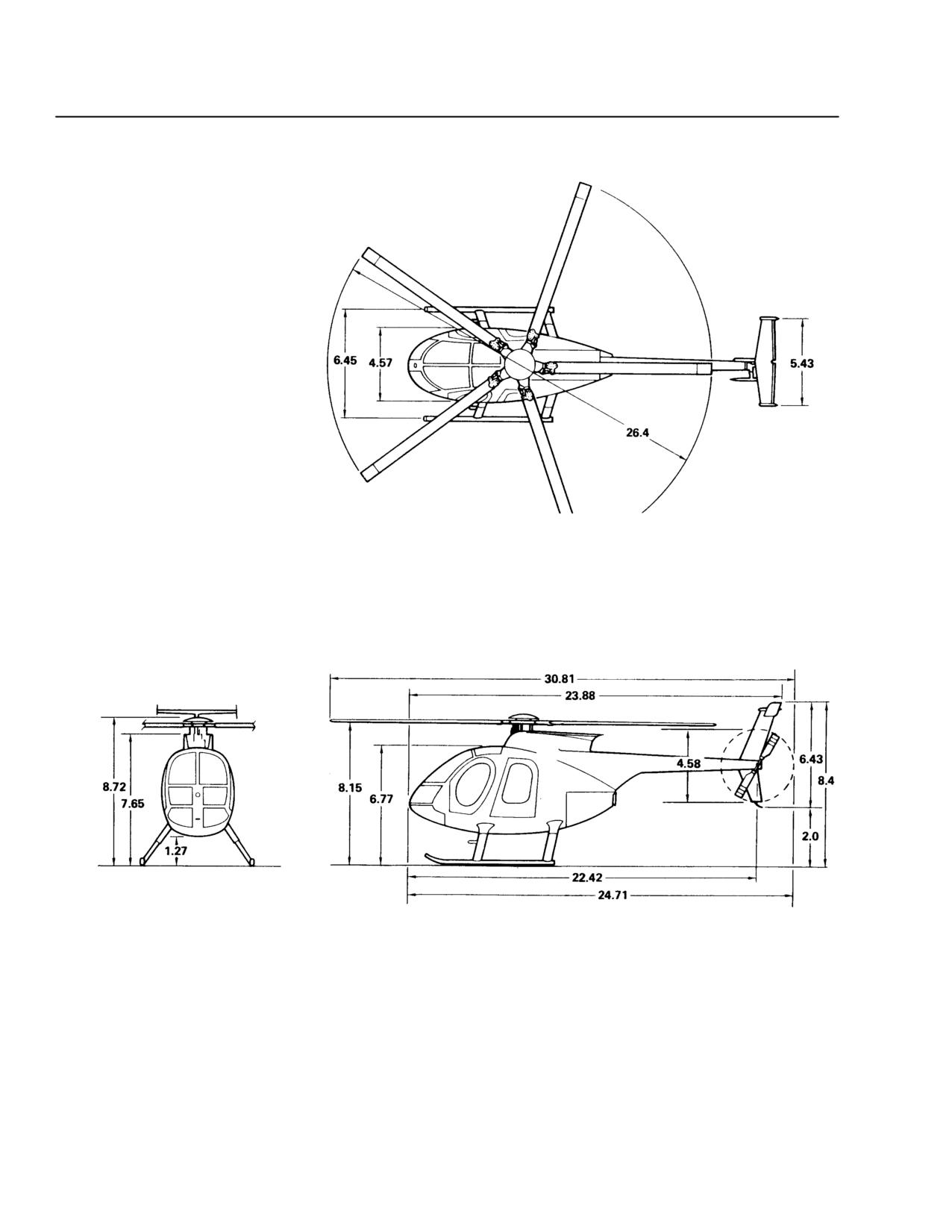
CSP-E-1
ROTORCRAFT FLIGHT MANUAL
MD 500E
(Model 369E)
General
NOTES:
1. HELICOPTER ON GROUND WITH
FULL FUEL. TYPICAL ATTITUDE
OF CARGO DECK 4.7 DEGREES
NOSE UP.
2. IF OPTIONAL EXTENDED
LANDING GEAR IS INSTALLED,
ADD 0.87 FEET TO ALL
VERTICAL DIMENSIONS.
3. ALL DIMENSIONS ARE IN
FEET.
F03-002
Figure 1-1. MD 500E Principal Dimensions - Standard Landing Gear
1-14
Revision 14
MD 500E
ROTORCRAFT FLIGHT MANUAL
CSP-E-1
(Model 369E)
General
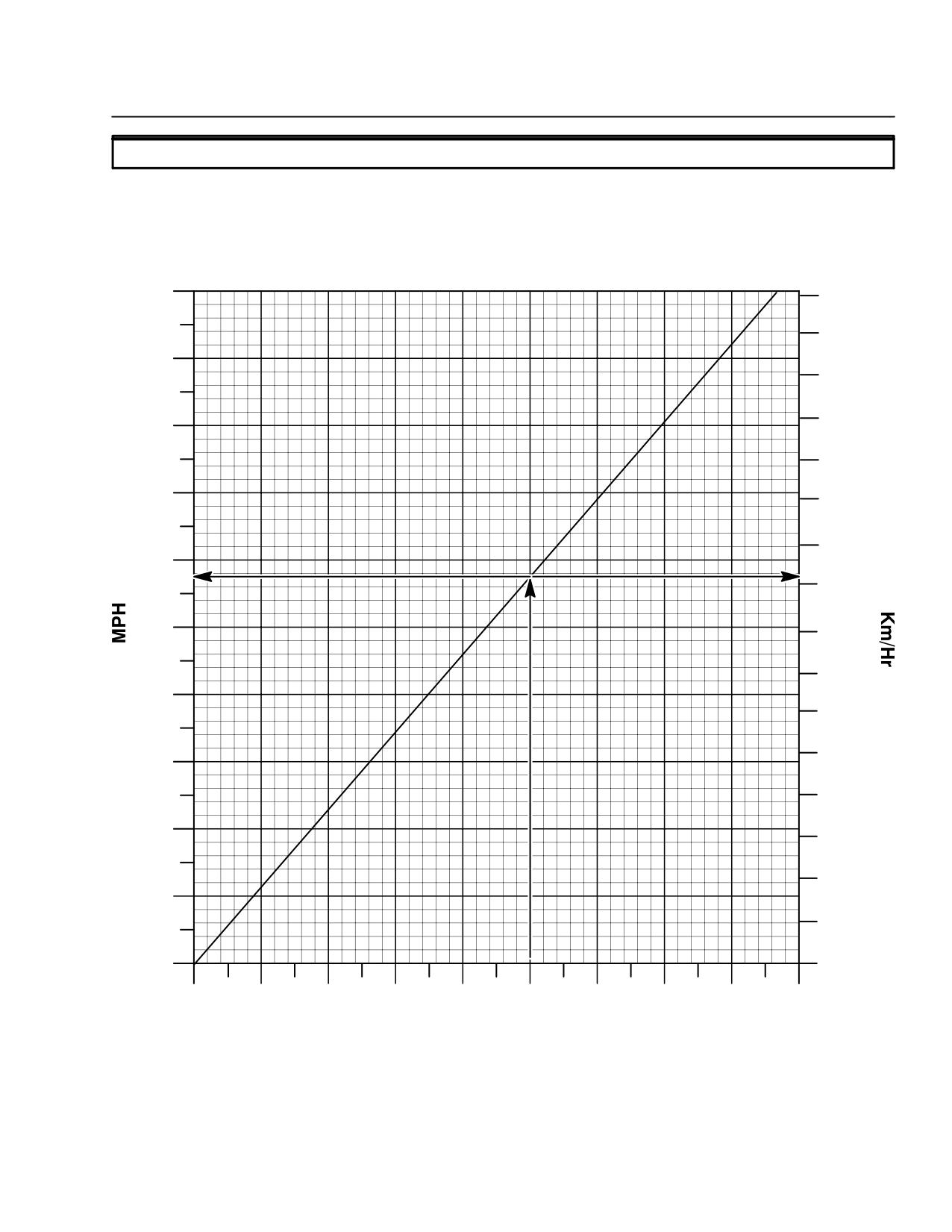
1-15. CONVERSION CHARTS AND TABLES
EXAMPLE: CONVERT 100 KNOTS TO MPH AND TO KM/HR:
ENTER CHART AT 100 KNOTS AND FOLLOW ARROW TO SLOPING LINE. TO FIND MPH, MOVE LEFT AND READ
115 MPH. TO FIND KM/HR, MOVE RIGHT FROM THE SLOPING LINE AND READ 185 KM/HR
200
320
300
180
280
260
160
240
140
220
200
120
180
100
160
140
80
120
100
60
80
40
60
40
20
20
0
0
0
20
40
60
80
100
120
140
160
180
Knots
F03-003
Figure 1-2. Speed: MPH/Knots/KmH
Revision 14
1-15
CSP-E-1
ROTORCRAFT FLIGHT MANUAL
MD 500E
(Model 369E)
General
TEMPERATURE
°
°F
C
140
60
EXAMPLE:
50
120
CONVERT °F TO °C
40
100
KNOWN:
30
TEMPERATURE = 50° F
80
20
METHOD:
60
ENTER AT 50° F
READ 10° C ACROSS ON °C SCALE
10
40
METHOD MAY BE REVERSED
0
TO FIND ° F WHEN ° C IS KNOWN
20
-10
ALTERNATE METHOD:
° F = (9/5 X °C) + 32
0
°C = 5/9(°F - 32)
-20
-20
-30
-40
-40
-50
−60
-60
-80
F03-004
Figure 1-3. Temperature Conversion Chart
1-16
Revision 14
MD 500E
ROTORCRAFT FLIGHT MANUAL
CSP-E-1
(Model 369E)
General
Table 1-3. Liquid Measure - U.S. Gallons to Liters
0
1
2
3
4
5
6
7
8
9
U.S.
Gallons
Liters
Liters
Liters
Liters
Liters
Liters
Liters
Liters
Liters
Liters
0
-
3.785
7.571
11.356
15.142
18.927
22.713
26.498
30.283
34.069
10
37.854
41.640
45.425
49.211
52.996
56.781
60.567
64.352
68.138
71.923
20
75.709
79.494
83.280
87.065
90.850
94.636
98.421
102.21
105.99
109.78
30
113.56
117.35
121.13
124.92
128.70
132.49
136.28
140.06
143.85
147.63
40
151.42
155.20
158.99
162.77
166.56
170.34
174.13
177.92
181.70
185.49
50
189.27
193.06
196.84
200.63
204.41
208.20
211.98
215.77
219.56
223.34
60
227.13
230.91
234.70
238.48
242.27
246.05
249.84
253.62
257.41
261.19
70
264.98
268.77
272.55
276.34
280.12
283.91
287.69
291.48
295.26
299.05
80
302.83
306.62
310.41
314.19
317.98
321.76
325.55
329.33
333.12
336.90
90
340.69
344.47
348.26
352.05
355.83
359.62
363.40
367.19
370.97
374.76
100
378.54
382.33
386.11
389.90
393.69
397.47
401.26
405.04
408.83
412.61
110
416.40
420.18
423.97
427.75
431.54
435.62
439.11
442.89
446.68
450.46
Table 1-4. Linear Measure
- Inches to Centimeters
0
1
2
3
4
5
6
7
8
9
Inches
Cm
Cm
Cm
Cm
Cm
Cm
Cm
Cm
Cm
Cm
0
-
2.54
5.08
7.62
10.16
12.70
15.24
17.78
20.32
22.86
10
25.40
27.94
30.48
33.02
35.56
38.10
40.64
43.18
45.72
48.26
20
50.80
53.34
55.88
58.42
60.96
63.50
66.04
68.58
71.12
73.66
30
76.20
78.74
81.28
83.82
86.36
88.90
91.44
93.98
96.52
99.06
40
101.60
104.14
106.68
109.22
111.76
114.30
116.84
119.38
121.92
124.46
50
127.00
129.54
132.08
134.62
137.16
139.70
142.24
144.78
147.32
149.86
60
152.40
154.94
157.48
160.02
162.56
165.10
167.64
170.18
172.72
175.26
70
177.80
180.34
182.88
185.42
187.96
190.50
193.04
195.58
198.12
200.66
80
203.20
205.74
208.28
210.82
213.36
215.90
218.44
220.98
223.52
226.06
90
228.60
231.14
233.68
236.22
238.76
241.30
243.84
246.38
248.92
251.46
100
254.00
256.54
259.08
261.62
264.16
266.70
269.24
271.78
274.32
276.86
Revision 14
1-17
CSP-E-1
ROTORCRAFT FLIGHT MANUAL
MD 500E
(Model 369E)
General
Table 1-5. Linear Measure
- Feet to Meters
0
1
2
3
4
5
6
7
8
9
Feet
Meters
Meters
Meters
Meters
Meters
Meters
Meters
Meters
Meters
Meters
0
-
0.305
0.610
0.914
1.219
1.524
1.829
2.134
2.438
2.743
10
3.048
3.353
3.658
3.962
4.267
4.572
4.877
5.182
5.466
5.791
20
6.096
6.401
6.706
7.010
7.315
7.620
7.925
8.229
8.534
8.839
30
9.144
9.449
9.753
10.058
10.363
10.668
10.972
11.277
11.582
11.887
40
12.192
12.496
12.801
13.106
13.411
13.716
14.020
14.325
14.630
14.935
50
15.239
15.544
15.849
16.154
16.459
16.763
17.068
17.373
17.678
17.983
60
18.287
18.592
18.897
19.202
19.507
19.811
20.116
20.421
20.726
21.031
70
21.335
21.640
21.945
22.250
22.555
22.859
23.164
23.469
23.774
24.070
80
24.383
24.688
24.993
25.298
25.602
25.907
26.212
26.517
26.822
27.126
90
27.431
27.736
28.041
28.346
28.651
28.955
29.260
29.565
29.870
30.174
100
30.479
30.784
31.089
31.394
31.698
32.003
32.308
32.613
32.918
33.222
Table 1-6. Weight
- Pounds to Kilograms
0
1
2
3
4
5
6
7
8
9
Pounds
Kilo-
Kilo-
Kilo-
Kilo-
Kilo-
Kilo-
Kilo-
Kilo-
Kilo-
Kilo-
grams
grams
grams
grams
grams
grams
grams
grams
grams
grams
0
-
0.454
0.907
1.361
1.814
2.268
2.722
3.175
3.629
4.082
10
4.536
4.990
5.443
5.897
6.350
6.804
7.257
7.711
8.165
8.618
20
9.072
9.525
9.979
10.433
10.886
11.340
11.793
12.247
12.701
13.154
30
13.608
14.061
14.515
14.969
15.422
15.876
16.329
16.783
17.237
17.690
40
18.144
18.597
19.051
19.504
19.958
20.412
20.865
21.319
21.772
22.226
50
22.680
23.133
23.587
24.040
24.494
24.948
25.401
25.855
26.308
26.762
60
27.216
27.669
28.123
28.576
29.030
29.484
29.937
30.391
30.844
31.298
70
31.751
32.205
32.659
33.112
33.566
34.019
34.473
34.927
35.380
35.834
80
36.287
36.741
37.195
37.648
38.102
38.555
39.009
39.463
39.916
40.370
90
40.823
41.277
41.730
42.184
42.638
43.091
43.545
43.998
44.453
44.906
100
45.359
45.813
46.266
46.720
47.174
47.627
48.081
48.534
48.988
49.442
1-18
Revision 14
MD 500E
ROTORCRAFT FLIGHT MANUAL
CSP-E-1
(Model 369E)
General
KNOTS
METERS/SEC
50
25
45
40
20
EXAMPLE
35
CONVERT KNOTS TO METERS/SEC
KNOWN:
30
WIND SPEED = 25 KT
15
METHOD:
ENTER CHART AT 25 KT READ APPROXIMATELY 13
METERS/SEC ACROSS ON METERS/SEC SCALE
25
METHOD MAY BE REVERSED
TO FIND KNOTS WHEN METERS/SEC ARE KNOWN
20
10
15
10
5
5
0
0
F03-005
Figure 1-4. Conversion Chart: Knots - Meters/Second
Revision 14
1-19
CSP-E-1
ROTORCRAFT FLIGHT MANUAL
MD 500E
(Model 369E)
General
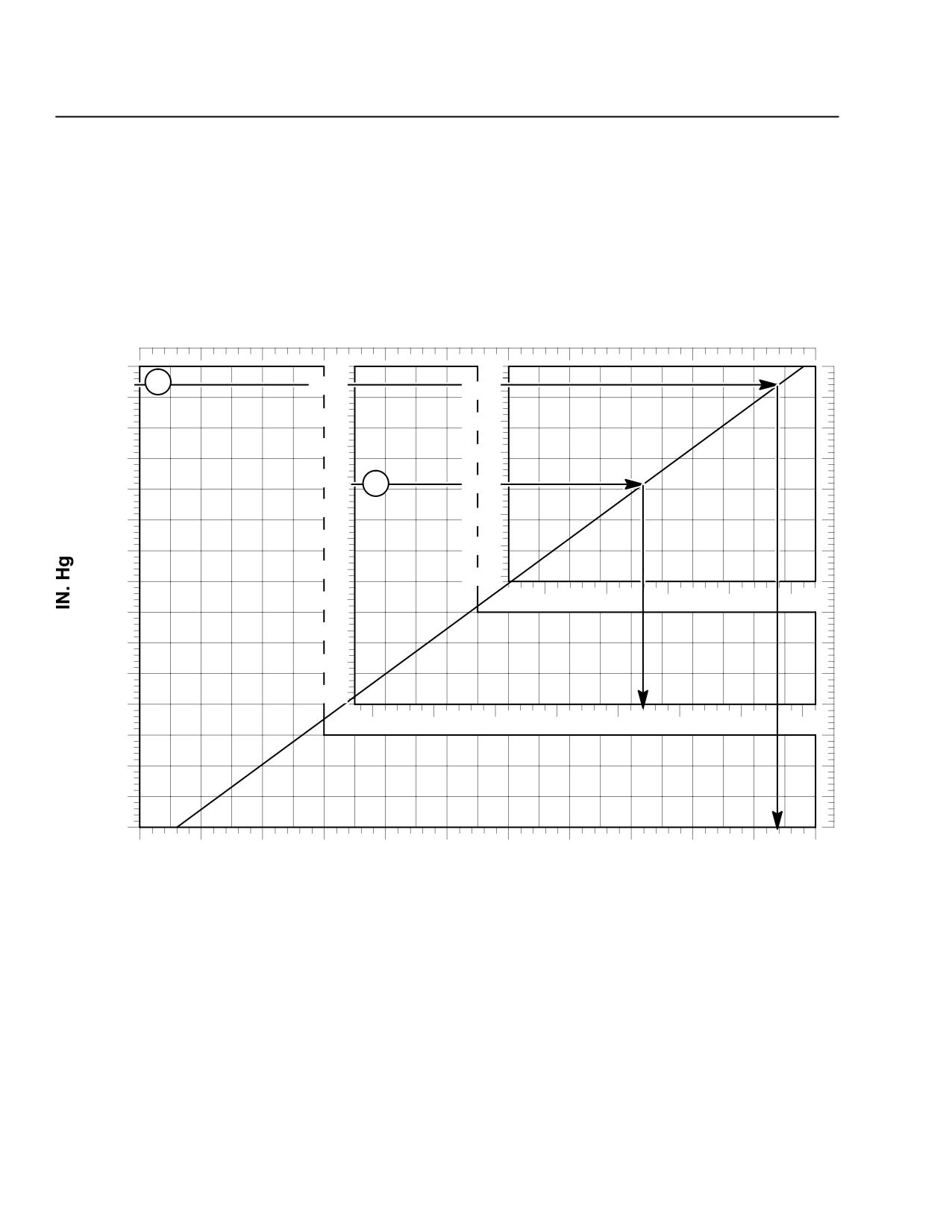
EXAMPLE 1: 29.44 IN. HG = 997 MBAR
EXAMPLE 2: 30.18 IN. HG = 1022 MBAR
29.5
1
30.5
31.1
29.4
30.4
31.0
29.3
30.3
30.9
29.2
30.2
2
30.8
29.1
30.1
30.7
29.0
30.0
30.6
28.9
29.9
30.5
28.8
29.8
1035
1040
1045
1050
1055
28.7
29.7
28.6
29.6
28.5
29.5
28.4
1000
1005
1010
1015
1020
1025
1030
1035
28.3
28.2
28.1
28.0
945
950
955
960
965
970
975
980
985
990
995
1000
MILLIBARS
F03-006
Figure 1-5. Conversion Chart: Inches of Mercury - Millibars
1-20
Revision 14
MD 500E
ROTORCRAFT FLIGHT MANUAL
CSP-E-1
(Model 369E)
General
Table 1-7. Standard Atmosphere Table
Standard Sea Level Conditions:
Temperature:
59°F (15°C)
Pressure:
29.921 in. Hg (1013.25 mbar)
Density:
0.0023769 slugs/ft3 (1.225 kg/m3)
TEMPERATURE
ALTITUDE
DENSITY
1
PRESSURE
PRESSURE
PRESSURE
(feet)
RATIO σ
pσ
(mbar)
(in. Hg)
RATIO
(°C)
(°F)
0
1.0000
1.000
15.00
59.000
1013.25
29.921
1.0000
1000
0.9711
1.0148
13.019
55.434
997.18
28.856
0.9644
2000
0.9428
1.0299
11.038
51.868
942.14
27.821
0.9298
3000
0.9151
1.0454
9.056
48.302
908.14
26.817
0.8962
4000
0.8881
1.0611
7.076
44.735
875.12
25.842
0.8637
5000
0.8617
1.0773
5.094
41.196
843.08
24.896
0.8320
6000
0.8359
1.0938
3.113
37.603
811.99
23.978
0.8014
7000
0.8106
1.1107
1.132
34.037
781.86
23.088
0.7716
8000
0.7860
1.1279
-0.850
30.471
752.63
22.225
0.7428
9000
0.7620
1.1456
-2.831
26.905
724.29
21.388
0.7148
10000
0.7385
1.1637
-4.812
23.338
696.82
20.577
0.6877
11000
0.7155
1.1822
-6.793
19.772
670.21
19.791
0.6614
12000
0.6932
1.2011
-8.774
16.206
644.40
19.029
0.6360
13000
0.6713
1.2205
-10.756
12.640
619.44
18.292
0.6113
14000
0.6500
1.2403
-12.737
9.074
595.23
17.577
0.5875
15000
0.6292
1.2606
-14.718
5.508
571.83
16.886
0.5643
16000
0.6090
1.2815
-16.669
1.941
549.14
16.216
0.5420
17000
0.5892
1.3028
-18.680
-1.625
527.23
15.569
0.5203
18000
0.5669
1.3246
-20.662
-5.191
505.99
14.942
0.4994
19000
0.5511
1.3470
-22.643
-8.757
485.48
14.336
0.4791
20000
0.5328
1.3700
-24.624
-12.323
465.63
13.750
0.4595
21000
0.5150
1.3935
-26.605
-15.899
446.47
13.184
0.4406
22000
0.4976
1.4176
-28.587
-19.456
427.91
12.636
0.4223
23000
0.4806
1.4424
-30.568
-23.002
409.99
12.107
0.4046
24000
0.4642
1.4678
-32.549
-26.588
392.72
11.597
0.3874
25000
0.4481
1.4938
-34.530
-30.154
375.99
11.103
0.3711
Revision 17
1-21
CSP-E-1
ROTORCRAFT FLIGHT MANUAL
MD 500E
(Model 369E)
General
This page intentionally left blank!
1-22
Revision 17
MD 500E
ROTORCRAFT FLIGHT MANUAL
CSP-E-1
(Model 369E)
Limitations
S E C T I O N I I
LIMITATIONS
TABLE OF CONTENTS
PARAGRAPH
PAGE
2-1.
Flight Restrictions
2-1
2-2.
Environmental Operating Conditions
2-2
2-3.
Airspeed Limitations
2-2
2-4.
Weight Limitations
2-3
Figure 2-1. Center of Gravity Envelope
2-3
2-5.
Rotor Brake Limitations (If Installed)
2-4
2-6.
Rotor RPM (Speed) Limitations
2-4
2-7.
Powerplant Limitations Rolls Royce 250-C20B
2-5
Figure 2-2. Maximum Allowable Output Shaft (N2 ) Limits (250-C20B) . . .
2-6
2-8.
Powerplant Limitations Rolls Royce 250-C20R/2
2-7
Figure 2-3. Maximum Allowable Output Shaft (N2 ) Limits (250-C20R/2)
2-8
2-9.
Electrical System Limitations
2-9
2-10. Starter Limitations
2-9
2-11. Fuel System Limitations
2-9
Table 2-1. Unusable Fuel: Standard Non Self-Sealing Fuel Tanks
2-10
Table 2-2. Unusable Fuel: Optional Self-Sealing Fuel Tanks
2-10
Figure 2-4. Operating Limitations when Using MIL-G-5572E Emergency
Fuel (Aviation Gasoline)
2-11
2-12. Instrumentation
2-12
Figure 2-5. Instruments (Sheet 1 of 3)
2-12
Figure 2-5. Instruments (Sheet 2 of 3)
2-13
Figure 2-5. Instruments (Sheet 3 of 3)
2-14
2-13. Placards and Decals
2-15
Figure 2-6. VNE Placards - Rolls Royce 250-C20B (Sheet 1 of 2)
2-15
Figure 2-6. VNE Placards - Rolls Royce 250-C20B (Sheet 2 of 2)
2-16
Figure 2-7. VNE Placards - Rolls Royce 250-C20R/2 (Sheet 1 of 2)
2-16
Figure 2-7. VNE Placards - Rolls Royce 250-C20R/2 (Sheet 2 of 2)
2-17
Figure 2-8. Decals and Placards
2-18
FAA Approved
Revision 17
2-i
CSP-E-1
ROTORCRAFT FLIGHT MANUAL
MD 500E
Limitations
(Model 369E)
This page intentionally left blank!
FAA Approved
2-ii
Revision 17
MD 500E
ROTORCRAFT FLIGHT MANUAL
CSP-E-1
(Model 369E)
Limitations
SECTION II
LIMITATIONS
NOTE: Unless otherwise stated, the restrictions and limitations put forth in this section
apply to MD 500E (Model 369E) Helicopters equipped with either the Rolls
Royce 250-C20B or 250-C20R/2 engines
2-1. FLIGHT RESTRICTIONS
Approved as a five place (maximum) helicopter.
Flight crew position:
The minimum flight crew consists of one pilot operating the helicopter from
the left seat with left-hand command controls. The right crew seat may be
used for an additional pilot when the approved dual controls are installed.
OR
The minimum flight crew consists of one pilot operating the helicopter from
the right seat with right-hand command controls. The left crew seat may
be used for an additional pilot when the approved dual controls are
installed.
Aerobatic flight is prohibited.
Hovering downwind with a cyclic trim failure (full forward) when wind is
above 15 knots is prohibited.
Installed equipment:
Certification is based on an Engine Failure Warning System, (including both
visual and audio indications), Low Rotor Warning System, Outside Air Tem-
perature gauge, and Fuel Low caution light being installed and operable.
Flight with doors removed is approved under the following conditions.
Approved doors-off configurations
All doors off.
Both rear doors off.
Both forward doors off.
Any one door off.
All loose items properly secured or stowed.
Unoccupied seat cushions and seat backs properly secured or stowed.
Any object that is not properly secured may exit the aircraft during
WARNING
flight. Items secured with Velcro tape should not be considered
properly secured (see Section IV, for Doors Off Flight).
VNE with doors removed: 130 KIAS or less - Ref. Figure 2-6
FAA Approved
Revision 14
2-1
CSP-E-1
ROTORCRAFT FLIGHT MANUAL
MD 500E
Limitations
(Model 369E)
Flight with center front seat occupied is approved under the following
conditions.
Dual controls removed.
Center location seatback and seat cushion installed and secured.
Seat belt(s) and shoulder harness(es) installed and operable.
2-2. ENVIRONMENTAL OPERATING CONDITIONS
Kinds of operations:
This rotorcraft is certified in the normal helicopter category for day and
night VFR operation when the appropriate instruments and equipment re-
quired by the airworthiness and/or operating rules are approved, installed
and are in operable condition.
Maximum operating altitude:
Maximum operating density altitude is 16,000 feet.
Ambient temperature limitations:
From sea level to 6000 feet pressure altitude the maximum engine air inlet
ambient temperature is 54°C (130°F); from 6000 feet to 20,000 feet pressure
altitude the maximum temperature varies linearly from 54°C to 27°C (130°F
to 80°F), respectively. It is to be assumed that engine air inlet temperature
is the same as ambient (free air) temperature.
Cold weather operations:
Flight into known icing conditions is prohibited.
Flight operation is permitted in falling and/or blowing snow only when the
Automatic Engine Reignition Kit and Engine Failure Warning System are
installed and operable.
2-3. AIRSPEED LIMITATIONS
VNE is 152 KIAS or less (Ref. Figure 2-6 and Figure 2-7).
VNE is 130 KIAS (``barber pole'' on airspeed indicator) or less during autorota-
tion (Ref. Figure 2-6 and Figure 2-7).
VNE is 130 KIAS or less when carrying less than 35 pounds of fuel (Ref.
Figure 2-6 and Figure 2-7).
VNE is 130 KIAS or less during doors off flight (Ref. Figure 2-6 and
Figure 2-7).
FAA Approved
2-2
Revision 13
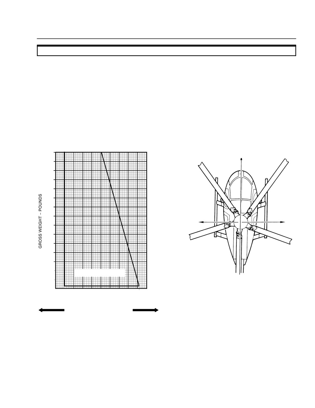
MD 500E
ROTORCRAFT FLIGHT MANUAL
CSP-E-1
(Model 369E)
Limitations
2-4.
WEIGHT LIMITATIONS
Maximum gross weight: 3000 lbs.
Minimum flying gross weight: 1538 lbs.
Cargo deck capacity: 1300 lbs. (not to exceed 115 lbs. per square foot).
Utility stowage compartment:
Maximum weight in the utility stowage compartment is 50 pounds.
CG Limits:
Ensure helicopter CG and weight are within approved limits throughout
flight (Ref. Figure 2-1).
3000
FORWARD
2800
2600
2400
LATERAL
LATERAL
‘‘-’’ CG
‘‘+’’ CG
2200
2000
1800
MINIMUM FLYING WEIGHT
1538 POUNDS
1600
AIRCRAFT CENTERLINE
98
99
100
102
104
106
108
107.4
LATERAL CG LIMITS
3 INCHES
FUSELAGE STATION - INCHES
F03-007
FORWARD
AFT
Figure 2-1. Center of Gravity Envelope
FAA Approved
Revision 13
2-3
CSP-E-1
ROTORCRAFT FLIGHT MANUAL
MD 500E
Limitations
(Model 369E)
2-5. ROTOR BRAKE LIMITATIONS (IF INSTALLED)
The rotor brake must be in the stowed position prior to engine starting.
The rotor brake may be applied after engine shutdown with the rotor at or be-
low 205 RPM.
2-6. ROTOR RPM (SPEED) LIMITATIONS
Normal Operating Range: 487 RPM to 492 RPM (102 - 103 percent N2 )
Power on: maximum RPM is 492 RPM (Ref 103 percent N2)
Power on: minimum RPM is 487 RPM (Ref 102 percent N2)
Power off: maximum RPM is 523 RPM (Ref 109 percent N2)
Power off: minimum RPM is 410 RPM (Ref 87 percent N2)
FAA Approved
2-4
Revision 13
MD 500E
ROTORCRAFT FLIGHT MANUAL
CSP-E-1
(Model 369E)
Limitations
2-7. POWERPLANT LIMITATIONS ROLLS ROYCE 250-C20B
Engine torque limits:
Maximum takeoff (5 minute): 87.2 psi torque.
Maximum continuous:
81.3 psi torque with TOT at or below 738°C.
74.3 psi torque with TOT greater than 738°C.
Transient torque limits:
87.3 to 93.0 psi torque for 15 seconds at 103 percent N2.
93.1 to 97.6 psi torque for 3 seconds at 103 percent N2.
Turbine outlet temperature limits:
Maximum takeoff (5 minute): 810°C
Maximum for starting (lightoff): 150°C
Maximum continuous:
755°C with torque at or below 74.3 psi torque.
738°C with torque greater than 74.3 psi torque.
Transient limits:
During start and shutdown: 810°C and above for 10 seconds or less with
a momentary peak temperature of 927°C for not more than 1 second.
During power changes in flight: 810°C to 843°C for 6 seconds.
Gas producer (N1) speed limits:
Maximum continuous: 105%.
Minimum: ground idle speed 64%.
Transient limits:
106% for 15 seconds.
Power turbine (N2) speed avoid range:
Steady-state operations between 75% and 88% are time limited and must
be recorded. Transition through the speed avoid range shall be accomplished
as quickly as possible.
Maximum cumulative steady-state time in the speed avoid range
CAUTIONis 1 minute.
NOTE: Refer to Rolls-Royce CEB A-1400.
FAA Approved
Revision 17
2-5
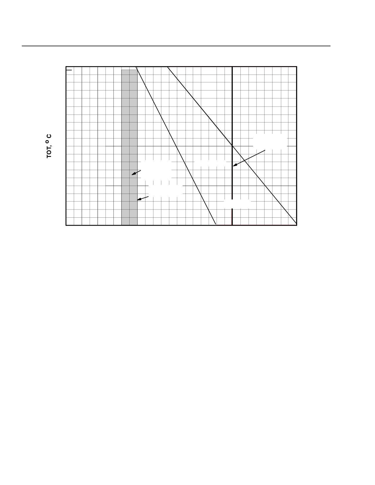
CSP-E-1
ROTORCRAFT FLIGHT MANUAL
MD 500E
Limitations
(Model 369E)
Power Turbine (N2) speed limits:
815
810
É
É
ÉÉÉÉÉ
É
ÉÉÉÉ
É
É
É
ÉÉÉÉÉ
É
ÉÉÉÉ
É
É
É
ÉÉÉÉ
É
ÉÉÉÉ
É
É
760
É ÉÉÉ
É
ÉÉÉÉ
É
É
ÉÉÉÉ
É
ÉÉÉÉ
É
É
ÉÉÉ
É
ÉÉÉÉ
É
É
ÉÉÉ
É
ÉÉÉÉ
É
É
704
POWER OF
É
É
É
F
É
ROTOR
LIMIT (REF)
É
É
É
É
É
É
ÉÉÉÉ
É
É
649
NORMAL
15 SECONDS
POWER-ON
É
É
ÉÉÉÉ
É
É
OPERATION
É
É
ÉÉÉÉ
É
É
É
É
ÉÉ
É
É
É
POWER ON
593
ROTOR LIMIT
É
É
ÉÉ
É
É
MAXIMUM
ÉÉ
É
É
É
É
ÉÉÉÉ
É
É
É
É
ÉÉÉÉ
É
É
538
99
100
101
102
103
104
105
106
107
108
109
110
111
112
113
PERCENT SPEED-OUTPUT SHAFT (N2)
F03-008
Figure 2-2. Maximum Allowable Output Shaft (N2 ) Limits (250-C20B)
Engine oil system limits:
Flight operation temperature limits: 0°C to 107°C
NOTE: These engine oil temperature limits pertain to all gauge configurations. 0°C is
when the needle is at the bottom of the yellow/green arc.
Flight operation pressure limits:
50 to 130 psi with the following minimums:
115 psi at 94 percent N1 and above.
90 psi at 79 percent N1.
50 psi below 79 percent N1.
FAA Approved
2-6
Revision 13
MD 500E
ROTORCRAFT FLIGHT MANUAL
CSP-E-1
(Model 369E)
Limitations
2-8. POWERPLANT LIMITATIONS ROLLS ROYCE 250-C20R/2
Engine torque limits:
Maximum takeoff power (5 minute): 87.2 psi torque
Maximum continuous: 81.3 psi torque
Transient torque limits:
87.3 to 93.0 psi torque for 15 seconds at 103 percent N2.
93.1 to 97.6 psi torque for 3 seconds at 103 percent N2.
Turbine Outlet Temperature limits:
Maximum takeoff (5 minute): 810°C
Maximum for starting (lightoff): 150°C
Maximum continuous: 752°C
Transient limits:
During start and shutdown: 810°C and above for 10 seconds or less with
a momentary peak temperature of 927°C for not more than 1 second.
During power changes in flight:
810°C to 843°C for 6 seconds for aircraft with ``analog only” TOT indica-
tor.
810°C to 899°C for 6 seconds for aircraft with ``analog/digital” TOT indi-
cator.
Gas Producer (N1) speed limits:
Maximum continuous: 105%.
Minimum: ground idle speed 64%.
Transient limits:
106% for 15 seconds.
Power turbine (N2) speed avoid range:
Steady-state operations between 75% and 88% are time limited and must
be recorded. Transition through the speed avoid range shall be accomplished
as quickly as possible.
Maximum cumulative steady-state time in the speed avoid range
CAUTIONis 1 minute.
NOTE: Refer to Rolls-Royce CEB A-72-4095.
FAA Approved
Revision 17
2-7
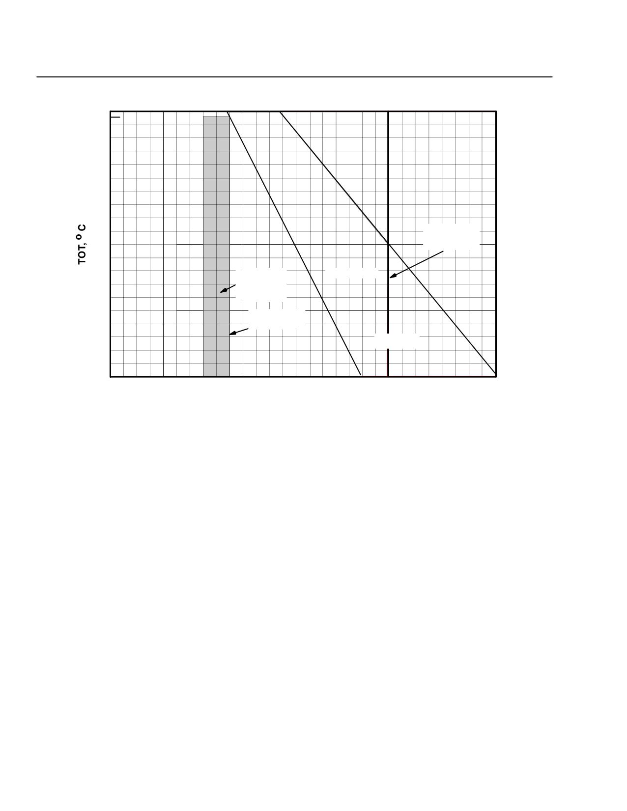
CSP-E-1
ROTORCRAFT FLIGHT MANUAL
MD 500E
Limitations
(Model 369E)
Power Turbine (N2) speed limits:
815
810
É
É
ÉÉÉÉÉ
É
ÉÉÉÉ
É
É
É
ÉÉÉÉÉ
É
ÉÉÉÉ
É
É
É
ÉÉÉÉ
É
ÉÉÉÉ
É
É
760
É ÉÉÉ
É
ÉÉÉÉ
É
É
ÉÉÉÉ
É
ÉÉÉÉ
É
É
ÉÉÉ
É
ÉÉÉÉ
É
É
ÉÉÉ
É
ÉÉÉÉ
É
É
704
POWER OF
É
É
É
F
É
ROTOR
LIMIT (REF)
É
É
É
É
É
É
ÉÉÉÉ
É
É
649
NORMAL
15 SECONDS
POWER-ON
É
É
ÉÉÉÉ
É
É
OPERATION
É
É
ÉÉÉÉ
É
É
É
É
ÉÉ
É
É
É
POWER ON
593
ROTOR LIMIT
É
É
ÉÉ
É
É
MAXIMUM
ÉÉ
É
É
É
É
ÉÉÉÉ
É
É
É
É
ÉÉÉÉ
É
É
538
99
100
101
102
103
104
105
106
107
108
109
110
111
112
113
PERCENT SPEED-OUTPUT SHAFT (N2)
F03-008
Figure 2-3. Maximum Allowable Output Shaft (N2 ) Limits (250-C20R/2)
Engine oil system limits:
Flight operation temperature limits: 0°C to 107°C
NOTE: These engine oil temperature limits pertain to all gauge configurations. 0°C is
when the needle is at the bottom of the yellow/green arc.
Flight operation pressure limits:
50 to 130 psi with the following minimums:
120 psi at 94 percent N1 and above.
90 psi at 79 percent N1.
50 psi below 79 percent N1.
FAA Approved
2-8
Revision 13
MD 500E
ROTORCRAFT FLIGHT MANUAL
CSP-E-1
(Model 369E)
Limitations
2-9.
ELECTRICAL SYSTEM LIMITATIONS
Generator limits:
Maximum continuous: 85 amps
85 to 150 amps: 10 minutes
>150 amps: 2 minute limit prior to takeoff during battery recharging cycle
only.
Battery limits:
Flight following a battery overtemperature of 160°F (71°C) or above is pro-
hibited until the battery has been inspected.
2-10. STARTER LIMITATIONS
If ignition is not attained:
1 minute on, 1 minute off;
1 minute on, 23 minutes off;
2-11. FUEL SYSTEM LIMITATIONS
Fuel Specifications:
For additional information on fuels, refer to the appropriate Rolls Royce Opera-
tion and Maintenance Manual.
Primary
Jet A (ASTM D-1655); Jet A-1 (ASTM D-1655); Jet B (ASTM-D-1655)
JP-1 conforming to ASTM D-1655, Jet A or Jet A-1
JP-4 (MIL-DTL-5624); JP-5 (MIL-DTL-5624); JP-8 (MIL-DTL-83133)
Arctic Diesel Fuel DF-A conforming to ASTM D-1655, Jet A or Jet A-1
Diesel No. 1 conforming to ASTM D-1655, Jet A or Jet A-1
Peoples Republic of China RP-3.
Alternate
AVGAS/JetA, A-1, JP-5 or JP-8 mixture may be used at ambient tem-
peratures of 4°C and below.
Refer to Rolls Royce Operation and Maintenance Manual for AVGAS
mix, cold weather fuel and blending instructions.
Emergency
Aviation Gasoline MIL-G-5572 (ASTM D 910).
MIL-G-5572 aviation gasolines containing Tri-Cresyl-Phosphate
CAUTION(TCP) additives shall not be used. Use of MIL-G-5572E gasolines is
limited to a maximum of 6 hours of operation per engine overhaul
period and operation within safe conditions. (Ref. Figure 2-4).
When using alternate fuel mixtures or emergency fuels, the start
CAUTIONpump should remain on until the engine is shutdown. (Ref.
Figure 2-4).
FAA Approved
Revision 14
2-9
CSP-E-1
ROTORCRAFT FLIGHT MANUAL
MD 500E
Limitations
(Model 369E)
Table 2-1. Unusable Fuel: Standard Non Self-Sealing Fuel Tanks
Imp.
U.S.
Pounds/
Fuel Type
Liters
Gal
Gal
Kilograms
Jet-A
7.2
1.6
1.9
13.1/5.9
Jet-B
7.2
1.6
1.9
12.5/5.7
Table 2-2. Unusable Fuel: Optional Self-Sealing Fuel Tanks
Imp.
U.S.
Pounds/
Fuel Type
Liters
Gal
Gal
Kilograms
Jet-A
7.9
1.7
2.1
14.3/6.5
Jet-B
7.9
1.7
2.1
13.6/6.2
Cold weather operations:
Fuels must meet anti-icing capability of JP-4 when operating at 4°C (40°F)
or less.
The 250-C20R/2 (SP) engine does not require fuel anti-ice additives above
fuel temperatures of -30° F (-34°C). However the continued use of anti-ice
additives under all temperature conditions is recommended to provide addi-
tional protection against fuel system icing and microbiological contamina-
tion.
Fuel filter:
Upon completion of the flight in progress, further flight is prohibited until
the fuel filter has been serviced following the illumination of the FUEL
FILTER caution light.
Fuel system purging:
Further flight is prohibited until the fuel system is purged (see HMI) following:
Engine flameout caused by fuel exhaustion.
Draining fuel from engine compartment fuel drains (if installed) without the
start pump on.
Engine shutdown using emergency fuel shutoff valve.
Motoring the helicopter engine without fuel in the fuel tank.
FAA Approved
2-10
Revision 13
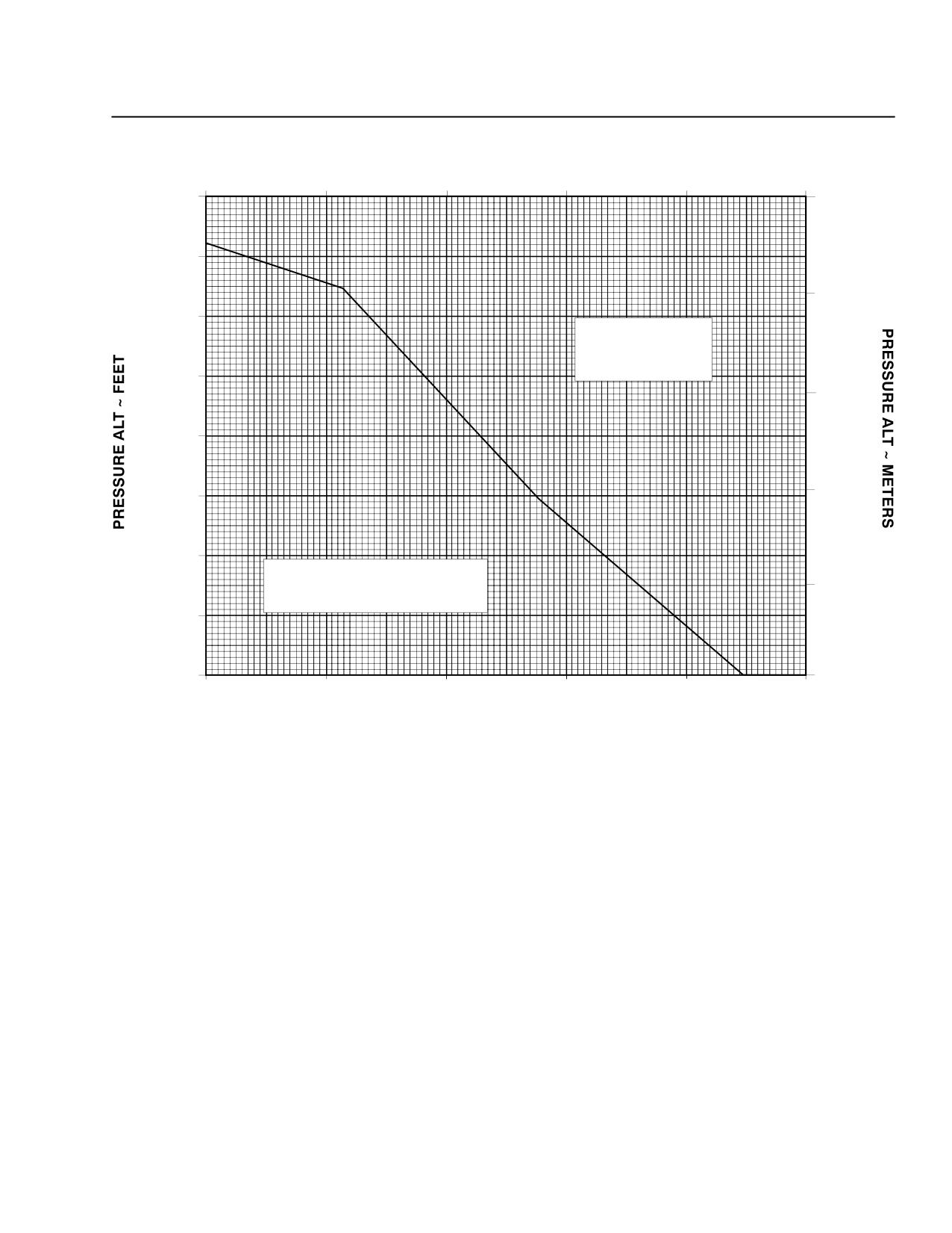
MD 500E
ROTORCRAFT FLIGHT MANUAL
CSP-E-1
(Model 369E)
Limitations
FUEL TEMPERATURE ~ DEG C
4
16
27
39
49
60
16,000ÉÉÉÉÉÉÉÉÉÉÉÉÉÉÉÉÉÉÉÉÉÉÉÉÉÉ
5,000
É
É
ÉÉÉÉ
É
ÉÉÉÉ
É
ÉÉÉÉ
É
ÉÉÉÉ
ÉÉÉÉÉ
14,000
É
É
ÉÉ
É
ÉÉÉÉ
É
ÉÉÉÉ
É
ÉÉÉÉ
ÉÉÉÉÉ
ÉÉ
ÉÉÉÉ
É
ÉÉÉÉ
É
ÉÉÉÉ
ÉÉÉÉÉ
4,000
É
ÉÉÉ
É
ÉÉÉÉ
É
ÉÉÉÉ
ÉÉÉÉÉ
12,000
É
ÉÉ
É
ÉÉÉÉ
ÉÉÉÉ
PROHIBITED
É
É
É
ÉÉÉÉ
ÉÉÉÉ
OPERATION
10,000
É
É
ÉÉÉÉ
ÉÉÉÉ
3,000
É
É
ÉÉÉÉ
ÉÉÉÉÉ
É
ÉÉÉÉ
É
ÉÉÉÉ
ÉÉÉÉÉ
É
ÉÉÉÉ
8,000
ÉÉÉÉ
ÉÉÉÉÉ
É
ÉÉÉÉ
ÉÉÉ
ÉÉÉÉÉ
É
ÉÉÉÉ
2,000
6,000
ÉÉ
ÉÉÉÉÉ
É
ÉÉÉÉ
É
ÉÉÉÉÉ
É
ÉÉÉÉ
É ÉÉÉ
É
ÉÉÉÉ
4,000
É
ÉÉ
É
ÉÉÉÉ
SAFE OPERATION
1,000
(START FUEL PUMP ON)
ÉÉÉ
É
ÉÉÉÉ
2,000
ÉÉ
É
ÉÉÉÉ
É
É
ÉÉÉÉ
ÉÉÉÉ
0
0
40
60
80
100
120
140
FUEL TEMPERATURE ~ DEG F
NOTES:
1. USE OF MIL-G-5572E FUEL IS LIMITED TO
A MAXIMUM OF 6 HOURS OF OPERATION
PER ENGINE OVERHAUL PERIOD
2. TO CONSERVATIVELY ESTIMATE THE
FUEL TEMPERATURE, ASSUME IT TO BE
EQUAL TO THE HIGHEST TEMPERATURE
THE HELICOPTER HAS BEEN EXPOSED TO
DURING THE PRECEDING 24 HOURS
F03-009
Figure 2-4. Operating Limitations when Using MIL-G-5572E Emergency
Fuel (Aviation Gasoline)
FAA Approved
Revision 13
2-11
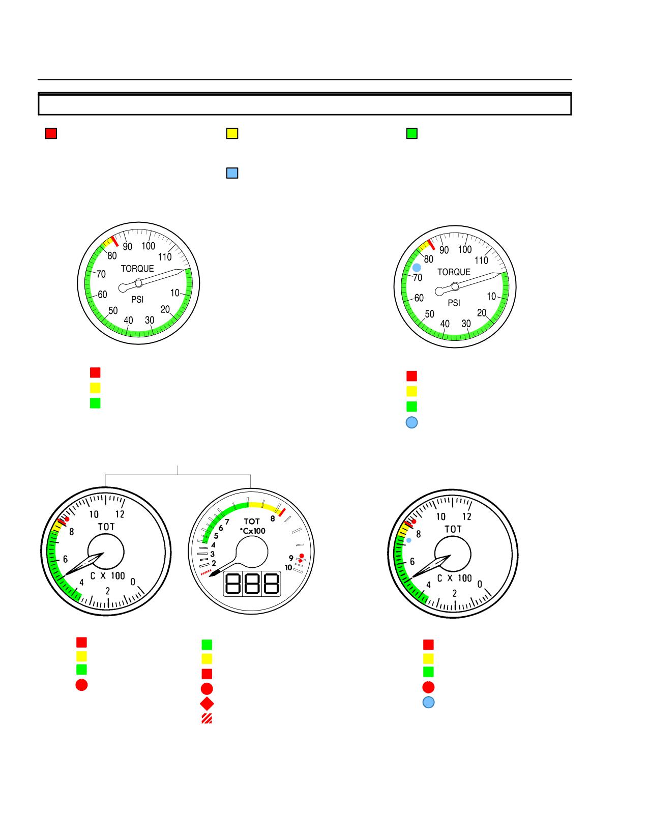
CSP-E-1
ROTORCRAFT FLIGHT MANUAL
MD 500E
Limitations
(Model 369E)
2-12. INSTRUMENTATION
RED
YELLOW
GREEN
RED INDICATES MAXIMUM AND
YELLOW INDICATES CAUTIONARY
GREEN INDICATES NORMAL
MINIMUM OPERATING LIMITS; THE
OPERATING RANGE.
OPERATING RANGE.
EDGE OF A RED LINE IS THE
BLUE
LIMITING VALUE; THE POINTER
BLUE INDICATES SPECIAL
SHOULD NOT ENTER THE RED
OPERATING CONDITIONS
DURING NORMAL OPERATIONS
TORQUEMETER (C20R/2)
TORQUEMETER (C20B)
87.2 PSI
87.2 PSI
81.3 TO 87.2 PSI
81.3 TO 87.2 PSI
0 TO 81.3 PSI
0 TO 81.3 PSI
74.3 PSI
TURBINE OUTLET TEMPERATURE (C20/R2)
TURBINE OUTLET TEMPERATURE (C20B)
ANALOG
ANALOG / DIGITAL
ANALOG
810°C
400 TO 752°C
810°C
752 TO 810°C
752 TO 810°C
755 TO 810°C
360 TO 752°C
810°C
360 TO 755°C
843°C
899°C
843°C
927°C
738°C
150°C
F03-010-1
Figure 2-5. Instruments (Sheet 1 of 3)
FAA Approved
2-12
Revision 13
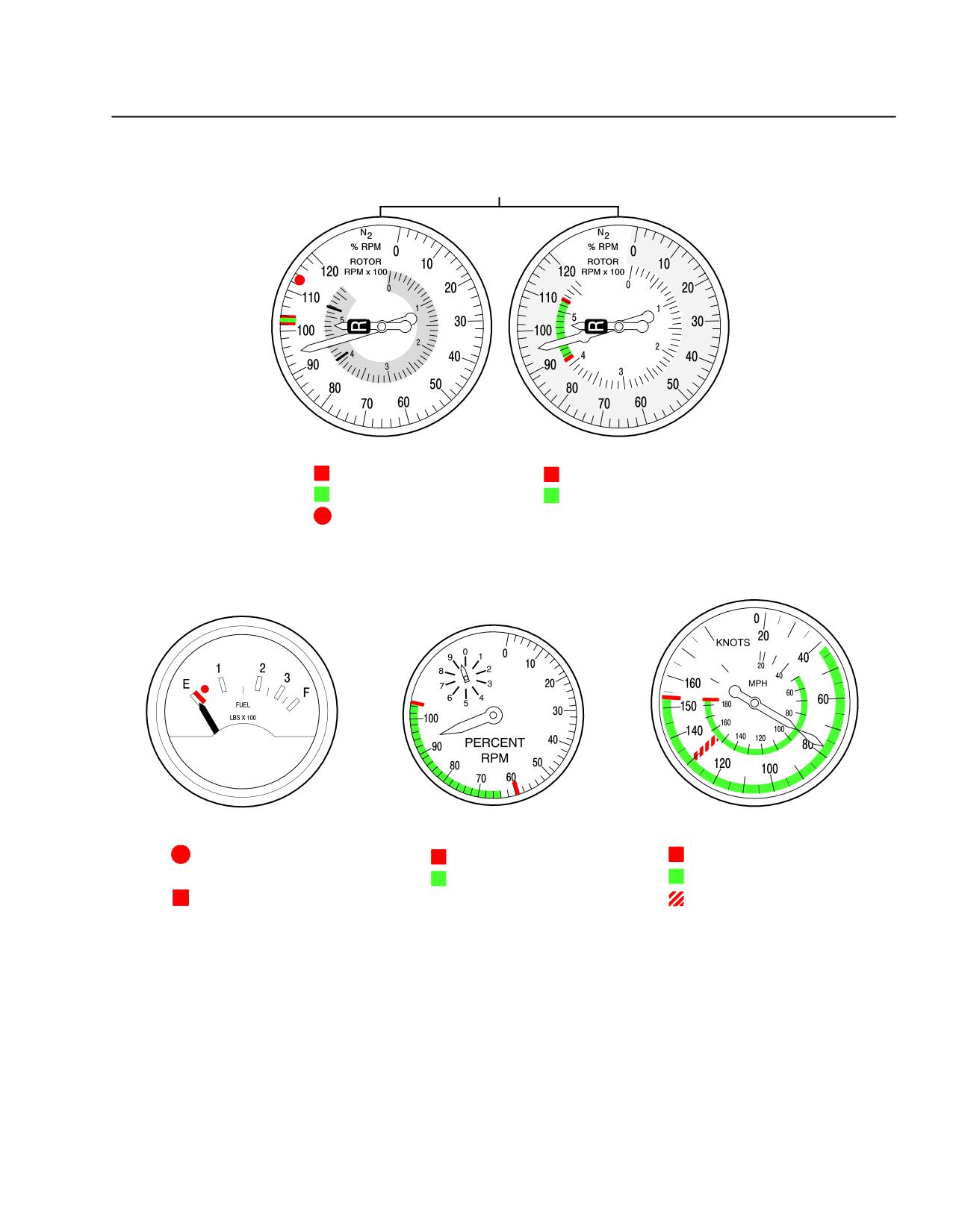
MD 500E
ROTORCRAFT FLIGHT MANUAL
CSP-E-1
(Model 369E)
Limitations
DUAL TACHOMETER
(FACE SHOWN TWICE FOR CLARITY)
N2 RPM
ROTOR RPM
102 AND 103%
410 AND 523 RPM
102 TO 103%
410 TO 523 RPM
113%
FUEL QUANTITY
N1 TACHOMETER
AIRSPEED
35 POUNDS
59 AND 105%
152 KNOTS
64 TO 105%
42 TO 152 KNOTS
12.5 POUNDS
MAX AUTOROTATION SPEED
130 KNOTS
F03-010-2A
Figure 2-5. Instruments (Sheet 2 of 3)
FAA Approved
Revision 13
2-13
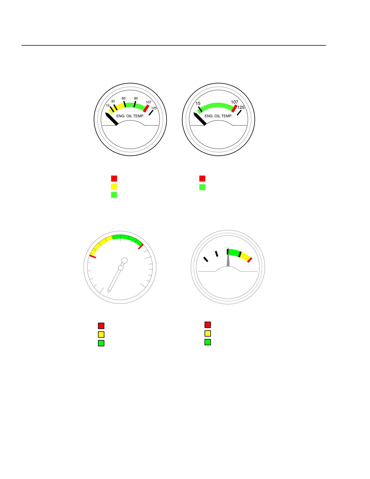
CSP-E-1
ROTORCRAFT FLIGHT MANUAL
MD 500E
Limitations
(Model 369E)
°C
°C
ENGINE OIL TEMPERATURE
ENGINE OIL TEMPERATURE
EARLIER CONFIGURATION
LATER CONFIGURATION
107°C
107°C
0° TO 54°C
0° TO 107°C
54° TO 107°C
0
100
75
85
150
150
50
150
-
+
D.C.
AMPS
0
OIL
PRESS
PSI
ENGINE OIL PRESSURE
AMMETER
50 AND 130 PSI
150 AMPS
50 TO 90 PSI
85 TO 150 AMPS
90 TO 130 PSI
0 TO 85 AMPS
F03-010-3
Figure 2-5. Instruments (Sheet 3 of 3)
FAA Approved
2-14
Revision 13
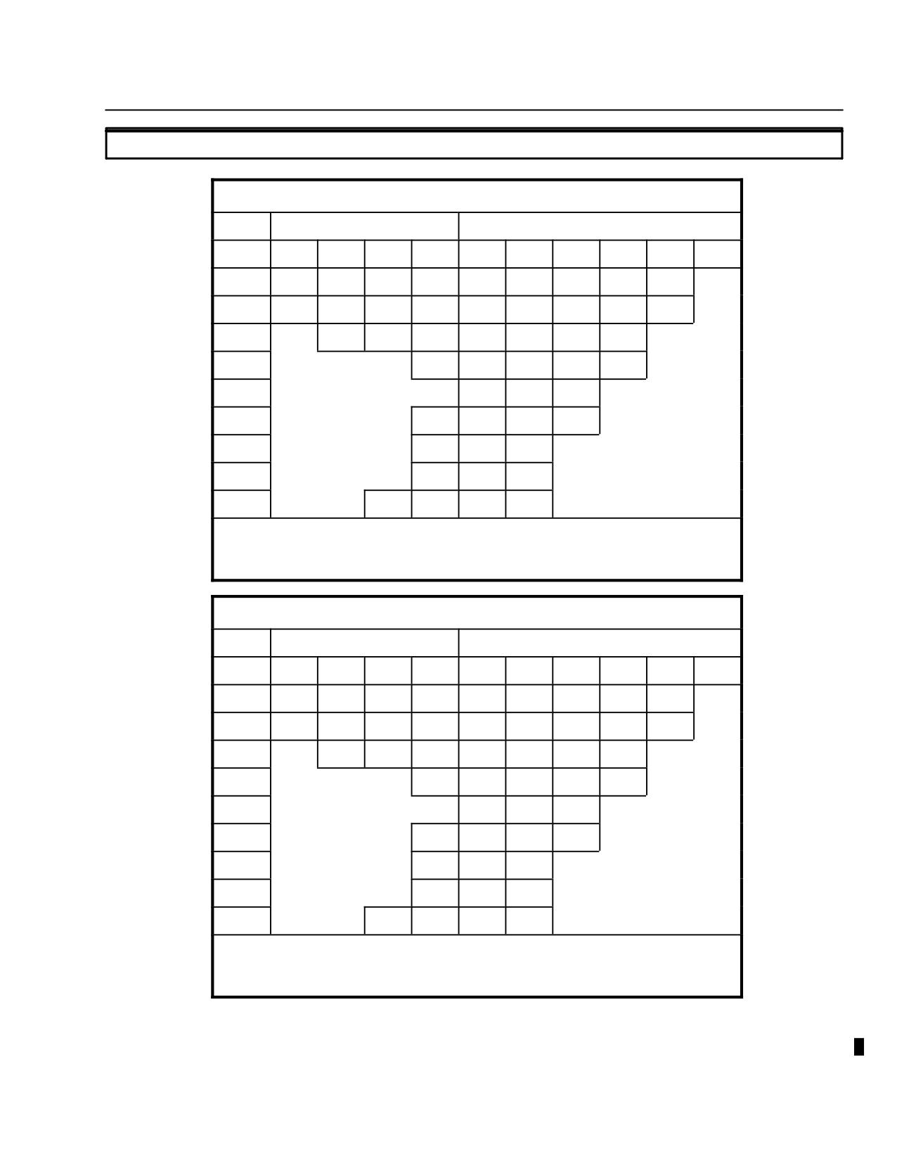
MD 500E
ROTORCRAFT FLIGHT MANUAL
CSP-E-1
(Model 369E)
Limitations
2-13. PLACARDS AND DECALS
VNE IAS (KNOTS)
OAT
PRESS ALT X 1000
GROSS WT = 2000 OR LESS
°C
0
2
4
6
8
10
12
14
16
18
−30
141
136
131
127
122
118
113
109
104
−20
149
144
139
134
129
124
119
115
101
−10
151
145
140
135
130
125
110
0
146
141
136
121
102
10
152
146
137
111
20
151
143
123
104
30
148
140
114
NO FLIGHT
40
144
127
106
45
150
143
122
103
FOR AUTOROTATION VNE REDUCE SPEED BY 22K
(85K MIN); DO NOT EXCEED CHART VNE
MAX VNE 130 KTS WITH LESS THAN 35 LB FUEL
VNE IAS (KNOTS)
OAT
PRESS ALT X 1000
GROSS WT = 2001 TO 2500 LB
°C
0
2
4
6
8
10
12
14
16
18
−30
141
136
131
127
122
118
113
104
90
−20
149
144
139
134
129
124
113
96
84
−10
151
145
140
135
123
104
90
0
146
138
113
97
85
10
152
124
105
91
20
143
115
98
86
30
127
107
93
NO FLIGHT
40
117
100
88
45
137
113
98
85
FOR AUTOROTATION VNE REDUCE SPEED BY 22K
(90K MIN); DO NOT EXCEED CHART VNE
MAX VNE 130 KTS WITH LESS THAN 35 LB FUEL
Figure 2-6. VNE Placards - Rolls Royce 250-C20B (Sheet 1 of 2)
FAA Approved
Revision 14
2-15
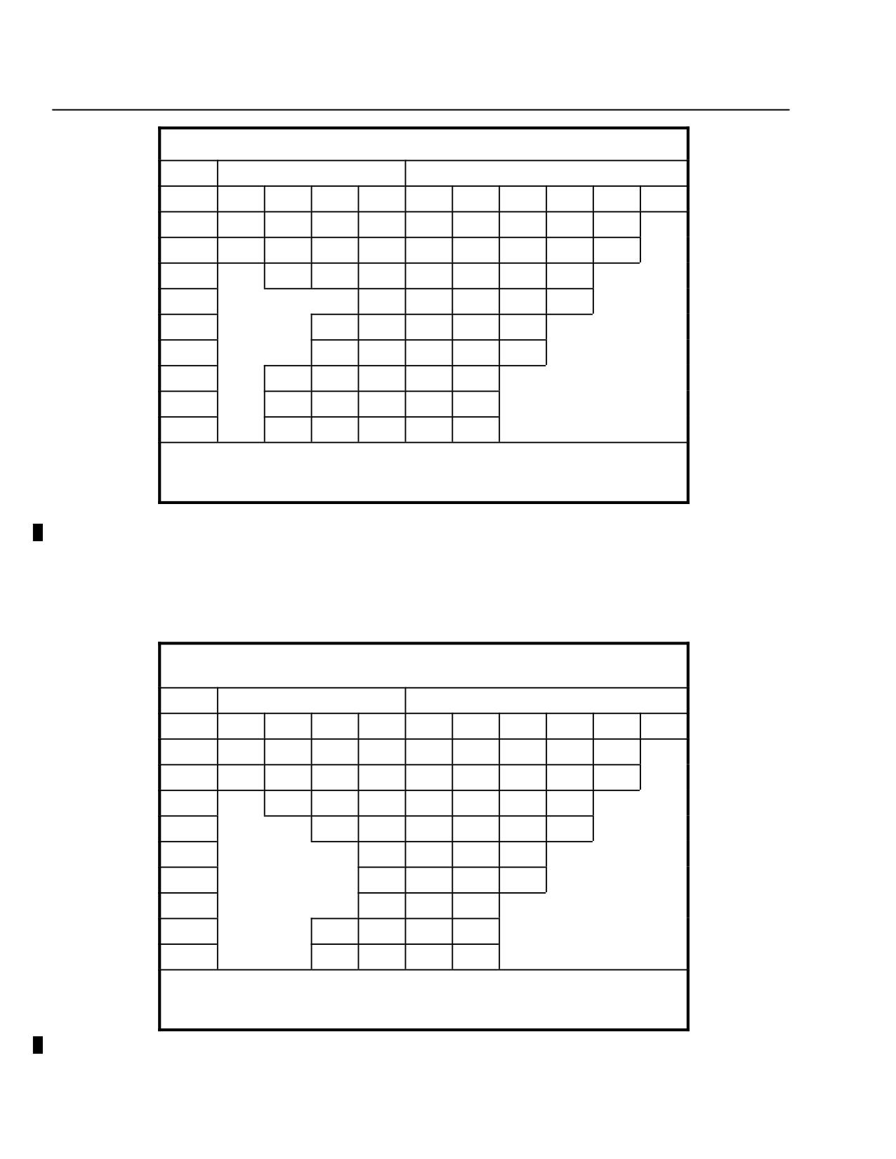
CSP-E-1
ROTORCRAFT FLIGHT MANUAL
MD 500E
Limitations
(Model 369E)
VNE IAS (KNOTS)
OAT
PRESS ALT X 1000
GROSS WT = 2501 TO 3000 LB
°C
0
2
4
6
8
10
12
14
16
18
−30
141
136
131
127
122
115
100
85
73
−20
149
144
139
134
125
106
92
79
67
−10
151
145
139
115
99
85
73
0
125
107
93
80
68
10
152
140
116
100
86
74
20
126
108
94
81
69
30
144
117
102
88
76
NO FLIGHT
40
129
110
95
82
71
45
124
106
93
80
69
FOR AUTOROTATION VNE REDUCE SPEED BY 22K
(95K MIN); DO NOT EXCEED CHART VNE
MAX VNE 130 KTS WITH LESS THAN 35 LB FUEL
Figure 2-6. VNE Placards - Rolls Royce 250-C20B (Sheet 2 of 2)
250-C20R/ 2
VNE IAS (KNOTS)
OAT
PRESS ALT X 1000
GROSS WT = 2000 LB OR LESS
°C
0
2
4
6
8
10
12
14
16
18
−30
141
136
131
126
122
117
113
108
104
−20
148
143
138
133
129
124
119
114
100
−10
150
145
138
135
130
125
108
0
151
146
141
135
116
101
10
152
145
133
109
20
149
142
119
102
30
146
137
111
NO FLIGHT
40
150
143
122
104
45
148
142
117
101
FOR AUTOROTATION VNE REDUCE SPEED BY 21K
(85K MIN); DO NOT EXCEED CHART VNE
MAX VNE 130 KTS WITH LESS THAN 35 LB FUEL
Figure 2-7. VNE Placards - Rolls Royce 250-C20R/2 (Sheet 1 of 2)
FAA Approved
2-16
Revision 14
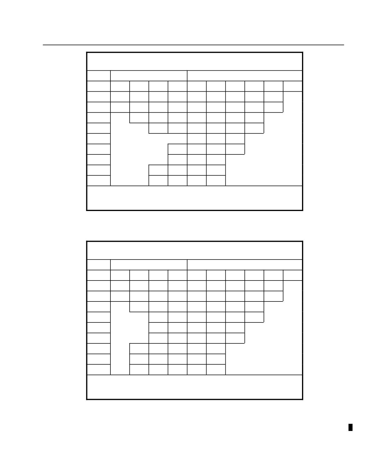
MD 500E
ROTORCRAFT FLIGHT MANUAL
CSP-E-1
(Model 369E)
Limitations
250-C20R/ 2
VNE IAS (KNOTS)
OAT
PRESS ALT X 1000
GROSS WT = 2001 TO 2500 LB
°C
0
2
4
6
8
10
12
14
16
18
−30
141
136
131
126
122
117
113
97
83
−20
148
143
138
133
129
124
105
89
78
−10
150
145
140
135
116
97
83
0
151
146
129
106
90
78
10
152
117
98
84
20
132
107
91
79
30
119
100
86
NO FLIGHT
40
138
110
93
81
45
128
106
91
79
FOR AUTOROTATION VNE REDUCE SPEED BY 21K
(90K MIN); DO NOT EXCEED CHART VNE
MAX VNE 130 KTS WITH LESS THAN 35 LB FUEL
250-C20R/ 2
VNE IAS (KNOTS)
OAT
PRESS ALT X 1000
GROSS WT = 2501 TO 3000 LB
°C
0
2
4
6
8
10
12
14
16
18
−30
141
136
131
126
122
111
94
80
68
−20
148
143
138
133
122
101
86
74
62
−10
150
145
140
110
93
80
68
0
151
122
102
87
74
63
10
152
141
111
94
81
69
20
124
103
88
76
64
30
144
113
96
82
71
NO FLIGHT
40
126
105
90
77
66
45
121
101
87
75
64
FOR AUTOROTATION VNE REDUCE SPEED BY 21K
(95K MIN); DO NOT EXCEED CHART VNE
MAX VNE 130 KTS WITH LESS THAN 35 LB FUEL
Figure 2-7. VNE Placards - Rolls Royce 250-C20R/2 (Sheet 2 of 2)
FAA Approved
Revision 14
2-17
CSP-E-1
ROTORCRAFT FLIGHT MANUAL
MD 500E
Limitations
(Model 369E)
Minimum N1 Speed
Starting Recommendations
OAT, °C
-18 AND BELOW
-18 TO 7
7 AND ABOVE
N1%
12
13
15
THIS HELICOPTER MUST BE OPERATED IN COMPLIANCE WITH THE OPERATING
LIMITATIONS SPECIFIED IN THE APPROVED ROTORCRAFT FLIGHT MANUAL.
CAUTION CYCLIC
FORCES TO BE TRIMMED
TO NEUTRAL DURING
STARTUP AND SHUTDOWN
NOTE: Above placards located on instrument panel.
50 POUNDS MAXIMUM LOAD UNIFORMLY DISTRIBUTED
NOTE: Above placard located inside utility stowage compartment.
IF MOISTURE VISIBLE
AND OAT BELOW 5°C
USE ANTI-ICE
NOTE: Above placard located by OAT gauge.
Figure 2-8. Decals and Placards
FAA Approved
2-18
Revision 13
MD 500E
ROTORCRAFT FLIGHT MANUAL
CSP-E-1
(Model 369E)
Emergency and
Malfunction Procedures
S E C T I O N I I I
EMERGENCY AND
MALFUNCTION PROCEDURES
TABLE OF CONTENTS
PARAGRAPH
PAGE
3-1.
General
3-1
3-2.
Warning and Caution Indicators
3-2
Figure 3-1. Warning and Caution Indicators
3-2
3-3.
Engine Failure
3-3
Complete Power Loss
3-3
Partial Power Loss
3-5
3-4.
Air Restart - Engine
3-6
3-5.
Low Rotor Speed
3-7
3-6.
Emergency Landing Procedures
3-7
Water Landing
3-7
3-7.
Fire
3-9
Engine Fire on the Ground
3-10
Engine Fire During Flight
3-11
Cabin Fire/Smoke
3-12
3-8.
Engine FUEL Control System Malfunctions
3-14
Fuel Control or Power Turbine governor Failure
3-14
3-9.
Other Engine Caution Indications
3-16
Engine Chip Detector
3-16
Low Engine Oil Pressure
3-16
Engine Torque
3-16
3-10. Main Rotor and Tail rotor Transmission Malfunctions
3-17
M/R Transmission Oil Pressure
3-17
M/R Transmission Oil Temperature
3-17
M/R Transmission Chip Detector
3-17
Tail rotor Transmission Chip Detector
3-17
3-11. Flight Control Malfunctions
3-18
Anti-Torque Failure
3-18
One Way Lock Failure
3-19
FAA Approved
Revision 14
3-i
CSP-E-1
ROTORCRAFT FLIGHT MANUAL
MD 500E
(Model 369E)
Emergency and
Malfunction Procedures
PARAGRAPH
PAGE
Cyclic Trim Failure
3-20
3-12. Abnormal Vibrations
3-22
3-13. Fuel System Malfunctions
3-22
Fuel Filter
3-22
Fuel Low
3-23
3-14. Electrical System Malfunctions
3-24
Battery Overtemperature
3-24
Generator Malfunction
3-25
3-15. Other Malfunctions
3-26
Engine Air Particle Separator Filter Clogged (If installed)
3-26
3-16. Emergency Egress
3-27
Figure 3-2. Emergency Exits
3-27
3-17. Emergency Equipment
3-27
FAA Approved
3-ii
Revision 14
MD 500E
ROTORCRAFT FLIGHT MANUAL
CSP-E-1
(Model 369E)
Emergency and
Malfunction Procedures
SECTION III
EMERGENCY AND
MALFUNCTION PROCEDURES
3-1. GENERAL
The procedures contained in this section are recommendations to be followed in
the event of an emergency or malfunction that may potentially affect the safety
of the aircrew, passengers, aircraft, or personnel on the ground.
These procedures are recommended to minimize danger to the helicopter. How-
ever, these procedures should not limit the pilot from taking additional actions
if the situation warrants.
In the event of an emergency or malfunction, the pilot's primary consider-
ation is control of the aircraft. Then, the pilot must identify the problem
and perform the appropriate procedures relevant to the situation.
Terms such as ``land immediately'', ``land as soon as possible'', and ``land
as soon as practical'' are defined in Section I.
FAA Approved
Revision 14
3-1
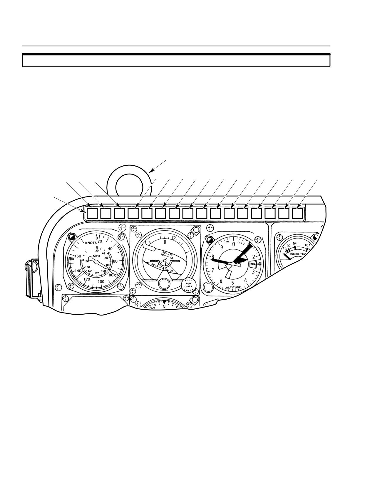
CSP-E-1
ROTORCRAFT FLIGHT MANUAL
MD 500E
(Model 369E)
Emergency and
Malfunction Procedures
3-2. WARNING AND CAUTION INDICATORS
Warning and caution indicators are located at the top of the instrument panel
(Ref. Figure 3-1).
A red warning or yellow caution indicator will illuminate and in some cases,
an audible warning will sound announcing a failure or malfunction.
Audible and visual warnings are provided for:
ENGINE OUT
LOW ROTOR
ENGINE OUT AUDIBLE
WARNING HORN
(SEE NOTE)
4
5
6
7
8
9
10
11
12
13
14
15
16
1
2
3
CAUTION AND
WARNING LIGHTS
1. ENGINE OUT
9. MAIN ROTOR TRANSMISSION CHIPS
2. TRANSMISSION OIL PRESSURE
10. TAIL ROTOR TRANSMISSION CHIPS
3. TRANSMISSION OIL TEMPERATURE
11. ENGINE CHIPS
4. BATTERY TEMPERATURE 160°F
12. GENERATOR OUT
5. BATTERY TEMPERATURE 140°F
13. AIR FRAME FILTER*
6. RE-IGN PRESS TO RESET
14. AIR FILTER CLOGGED*
7. FUEL LEVEL LOW
15. FLOAT PRESS TO TEST*
8. FUEL FILTER
16. PRESS TO TEST WARNING AND CAUTION LIGHTS
NOTE:
*OPTIONAL EQUIPMENT
ON LATER MODEL 369E HELICOPTERS,
ENGINE OUT AUDIBLE WARNING HORN
RELOCATED ADJACENT TO COCKPIT
F03-011
UTILITY LIGHT ON MAP CASE PANEL.
Figure 3-1. Warning and Caution Indicators
FAA Approved
3-2
Revision 14
MD 500E
ROTORCRAFT FLIGHT MANUAL
CSP-E-1
(Model 369E)
Emergency and
Malfunction Procedures
3-3. ENGINE FAILURE
COMPLETE POWER LOSS
ENGINE
Indications: Red
warning indicator ON and audible warning in headset.
OUT
Left yaw (due to a reduction in torque)
Drop in engine speed.
Drop in rotor speed.
Change in noise level.
NOTE: The amount of yaw is dependent upon the amount of torque at the moment of
power loss. High torque will cause a large yaw while low torque will cause a
relatively small yaw.
Respond immediately to the ENGINE OUT/low rotor RPM warning by
WARNING
adjusting collective to maintain rotor RPM within limits, then check
engine instruments and other indications to confirm engine trouble.
Conditions: The failure indicators are actuated when N1 falls below 55% or NR falls
below 468 NR (Ref. 98 ± 1% N2).
Procedures: Engine Failure - In Cruise at 500 Feet AGL or Above
F Adjust collective pitch according to altitude and airspeed to maintain rotor
speed between 410 and 523 RPM.
F Apply pedal pressure as necessary to control aircraft yaw.
F Adjust cyclic control as necessary to control airspeed and flight path. Al-
low airspeed to stabilize at 130 Knots IAS or lower (refer to VNE plac-
ards).
NOTE: At airspeeds above maximum autorotational VNE (130 KIAS or less Ref. Section II
VNE Placards), use aft cyclic to maintain aircraft’s attitude and slow to desired
airspeed as collective pitch is lowered. Increase collective as necessary after
entering autorotation to prevent rotor overspeed. If desired, operate at minimum
rotor speed to reduce rate of descent and/or extend glide distance.
The minimum rate of descent with power off will be attained at 60 KIAS and 410 NR.
FAA Approved
Revision 14
3-3
CSP-E-1
ROTORCRAFT FLIGHT MANUAL
MD 500E
(Model 369E)
Emergency and
Malfunction Procedures
The maximum glide distance with power off will be attained at 80 KIAS and 410 NR.
Glide distances attained during an actual engine out autorotation may be less than
the glide distances achieved during practice autorotations when operating at
reduced RPM (N2/NR needles joined).
F After confirming complete loss of power, time and altitude permitting,
place twistgrip in cutoff and close fuel shutoff valve.
F Select landing area and maneuver as required.
F If operating at reduced rotor RPM to extend glide or reduce rate of de-
scent, restore rotor RPM by lowering collective prior to flare out.
F Flare as required for the terrain to reduce forward speed and rate of de-
scent. Level aircraft before ground contact.
F Touch down in a level attitude, increasing collective pitch to cushion land-
ing.
F Avoid the use of aft cyclic or rapid lowering of the collective pitch during
initial ground contact or any subsequent ground slide.
FAA Approved
3-4
Revision 14
MD 500E
ROTORCRAFT FLIGHT MANUAL
CSP-E-1
(Model 369E)
Emergency and
Malfunction Procedures
Procedures: Engine Failure - Above 12 Feet and Below 500 Feet AGL
The Height - Velocity Diagram (Ref. Section V) depicts the combinations of air-
speeds vs. altitudes wherein a successful autorotation landing can be made in
the event of an engine failure. Flight within the cross-hatched regions repre-
sent airspeed/altitude combinations from which a successful autorotation land-
ing may be difficult to perform. Operation within the cross-hatched area
should be undertaken with caution.
F In the event of a power failure during takeoff/low level flight, the collec-
tive pitch must be initially lowered to maintain rotor speed. The amount
and duration of collective reduction depends upon the airspeed and height
above the ground at which the power loss occurs.
F As the ground is approached, flare as required to reduce forward speed
and rate of descent.
F Touch down in a level attitude, increasing collective pitch to cushion land-
ing.
F Avoid the use of aft cyclic or rapid lowering of the collective during initial
ground contact or during ground slide.
Procedures: Engine Failure - Hovering Flight Below 12 Feet AGL
F Do not reduce collective pitch.
F Apply right pedal to prevent yawing.
F Increase collective pitch as necessary to cushion landing.
PARTIAL POWER LOSS
Indications: Under partial power conditions, the engine may operate smoothly with
reduced power or it may operate erratically with intermittent surges of
power.
Procedures:
F Turning the start pump ON may smooth out an erratic operating engine
and/or restore power enabling the pilot to fly to a favorable landing area.
However, do NOT disregard the need to land.
F If possible, fly at reduced power to the nearest safe landing area and land
as soon as possible. Be prepared for a complete power loss at any time.
FAA Approved
Revision 14
3-5
CSP-E-1
ROTORCRAFT FLIGHT MANUAL
MD 500E
(Model 369E)
Emergency and
Malfunction Procedures
3-4. AIR RESTART - ENGINE
Because the exact cause of engine failure cannot be determined in flight, the
decision to attempt a restart will depend on aircraft altitude, time available,
rate of descent, and potential landing areas.
CAUTION
Do not attempt restart if a malfunction is suspected.
Conditions: At low altitude or when time is critical.
Procedures:
F Close twist grip to cutoff position.
F Press start/ignition button immediately.
NOTE: Pressing the starter button actuates the igniter. If N1 is 18 percent or above, open
twist grip immediately to ground idle. N1 speeds of 25 to 40 percent are preferred
for coolest and fastest restarts. Maintain safe autorotational airspeed.
Conditions: When altitude and time permit.
Procedures:
F Perform normal engine start if N1 has decayed below 18 percent. Refer to
Section IV, Engine Starting.
F Recommended airspeed is 60 knots IAS.
F Advance twistgrip from ground idle to full open once N1 reaches 60 -
65%.
F Collective pitch: increase as required once N2/NR are 103%.
FAA Approved
3-6
Revision 14
MD 500E
ROTORCRAFT FLIGHT MANUAL
CSP-E-1
(Model 369E)
Emergency and
Malfunction Procedures
3-5. LOW ROTOR SPEED
ENGINE
Indications: Red
warning indicator ON and audible warning in headset.
OUT
Drop in rotor RPM.
Change in noise level.
NOTE: The LOW ROTOR warning is activated when NR falls below 468.
Conditions: Low rotor RPM will most commonly be associated with the following:
Engine Failure.
Transient rotor droop during large, rapid increases in power.
Governor failure producing an underspeed.
Procedures:
F Respond immediately to the low rotor RPM warning by adjusting collec-
tive to maintain rotor RPM within limits.
F Check other Caution/Warning indicators and engine instruments to con-
firm engine trouble and respond in accordance with appropriate proce-
dures in this section.
3-6. EMERGENCY LANDING PROCEDURES
WATER LANDING
Conditions: Power off.
Procedures:
F Adjust collective pitch as necessary to establish autorotation.
F If time permits, open doors and push door handle full down to prevent re-
latching.
F Make autorotative approach, flaring as required to minimize forward
speed at touchdown.
FAA Approved
Revision 14
3-7
CSP-E-1
ROTORCRAFT FLIGHT MANUAL
MD 500E
(Model 369E)
Emergency and
Malfunction Procedures
F Level aircraft and apply full collective pitch as contact is made with the
water.
F When aircraft begins to roll, lower collective to full down to minimize
blades skipping off the water.
F Release safety harness and clear the aircraft as soon as the rotor blades
have stopped turning
Do not inflate personal flotation gear before exiting aircraft. Safe
WARNING
exit will be restricted.
Conditions: Power on.
Procedures:
F Descend to hovering altitude over water.
F Open doors and push door handle full down to prevent relatching.
F Passengers and copilot exit aircraft.
F Fly a safe distance away from all personnel in the water to avoid injury.
F Close twistgrip to the cutoff position and perform a hovering autorotation.
F Allow aircraft to settle in a level attitude while applying full collective
pitch.
F When aircraft begins to roll, reduce collective to full down to minimize
blades skipping off the water.
F Release safety harness and exit the aircraft as soon as the blades have
stopped turning.
Do not inflate personal flotation gear before exiting aircraft. Safe
WARNINGexit will be restricted
FAA Approved
3-8
Revision 14
MD 500E
ROTORCRAFT FLIGHT MANUAL
CSP-E-1
(Model 369E)
Emergency and
Malfunction Procedures
3-7. FIRE
The safety of the helicopter occupants is the primary consideration when a fire
occurs. Therefore, if airborne, it is imperative that the pilot maintain control of
the aircraft and land immediately. If the fire occurs on the ground or upon
landing from an inflight fire, it is essential that the engine be shut down, crew
and passengers evacuated and fire fighting begun immediately. If the situation
permits, a ``MAYDAY'' radio call should be made before electrical power is OFF
to expedite assistance from fire fighting and rescue personnel.
Indications: A pilot must rely on his senses to detect fire on board the aircraft. The
sound of electrical arcing, the smell of burning insulation, or the sighting
of smoke and/or flame are all possible indicators of an on board fire. Also,
the pilot may be notified of an on board fire by personnel outside the
aircraft via visual or audio communication methods.
At unprepared landing sites, dried grass or brush may catch fire
CAUTIONif allowed to contact hot engine exhaust.
Procedures: Cabin Smoke and Fume Elimination
Smoke and fume accumulation in the cabin can impede the pilot’s
CAUTIONability to maintain control of the aircraft and execute a safe landing.
To protect the pilot and passengers from the effects of toxic fumes
and smoke, ventilate the cabin:
F
Cabin heat (if source of smoke is
OFF
the cabin heat duct)
F
Fresh air vent
OPEN
F
Pilot/Cabin door vents
OPEN AND FACING AFT
NOTE: If necessary, open pilot’s door (airspeed below 130 KIAS) to expedite smoke and
fume evacuation. Door will stabilize open a few inches in forward flight.
FAA Approved
Revision 14
3-9
CSP-E-1
ROTORCRAFT FLIGHT MANUAL
MD 500E
(Model 369E)
Emergency and
Malfunction Procedures
Procedures: Aircraft Evacuation
F A thorough preflight passenger briefing is essential for a quick and safe
evacuation of passengers and crew when fire is involved. How to release
seat belts, the opening of doors, the proper exiting of the helicopter
keeping head and hands low to avoid the main rotor, are all critical to
insure the safety of passengers and crew.
Procedures: Fire extinguisher
F Pilots should be familiar with the operating instruction and hazards
associated with the particular type of fire extinguisher installed in their
aircraft. Classes (type) of fire for which it is approved, operating
instructions, and hazards associated with its use are listed on the
extinguisher.
F Use of a fire extinguisher on a cabin fire while still airborne is NOT
recommended and should only be considered after all other means to
extinguish and control the fire have been tried. The pilot's first
responsibility is to fly the helicopter and land immediately. Once on the
ground, with passengers and crew evacuated, attention can be turned to
extinguishing the fire.
F If a fire extinguisher is discharged in the cabin, use only the amount of
extinguishing agent necessary to extinguish the fire. This will minimize
the adverse effects of the particular agent being used in a confined and
occupied space. Ventilate the cabin area as soon as possible after
extinguishing the fire.
Use extreme caution when attempting to extinguish an aircraft fire
WARNING
on the ground. The possibility of an explosion should not be
disregarded!
ENGINE FIRE ON THE GROUND
Conditions: Engine fire during starting
An engine fire during start could be caused by an overloading of fuel in
the combustion chamber and a delayed ignition of the fuel resulting in
flame emanating from the engine exhaust. This condition is normally
accompanied by a rapid rise in TOT. To extinguish the fire:
Procedures:
F
Twistgrip
CUTOFF
F
Starter
MOTOR UNTIL TOT IS BELOW 150°C
F
Fuel shut-off valve
PULL TO CLOSE
FAA Approved
3-10
Revision 14
MD 500E
ROTORCRAFT FLIGHT MANUAL
CSP-E-1
(Model 369E)
Emergency and
Malfunction Procedures
Conditions: Engine compartment fire
Procedures:
F
Twistgrip
CUTOFF
F
Fuel shutoff valve
PULL TO CLOSE
F
BAT/EXT switch
OFF
F
Passengers/crew
EVACUATE
IF TIME AND SITUATION PERMIT:
F
Rotor brake (if installed)
APPLY
F
Secure area
HAVE PASSENGERS AND SPECTATORS
MOVE A SAFE DISTANCE FROM THE AIR-
CRAFT
F
Fire extinguisher
USE AS APPROPRIATE
ENGINE FIRE DURING FLIGHT
Conditions: At low altitude (AGL)
Procedures:
F
Land immediately
POWER ON APPROACH AND LANDING
WITHOUT DELAY
F
Twistgrip
CUTOFF-AS SOON AS HELICOPTER IS ON
GROUND
F
Fuel shutoff valve
PULL TO CLOSE
F
BAT/EXT switch
OFF
F
Passengers/crew
EVACUATE
FAA Approved
Revision 14
3-11
CSP-E-1
ROTORCRAFT FLIGHT MANUAL
MD 500E
(Model 369E)
Emergency and
Malfunction Procedures
Conditions: At high altitude (AGL)
Procedures: Prevailing circumstances such as altitude (AGL), available landing areas,
and confirmation of engine fire must be considered in order to determine
whether to execute a power-on approach, as described for low altitude
(AGL) fires, or a power off autorotational descent to the ground. If a
power off descent is chosen proceed as follows.
F
Collective
DOWN TO ESTABLISH AUTOROTATION TO
SELECTED AREA
F
Twistgrip
CUTOFF
F
Fuel shutoff valve
PULL TO CLOSE
F
Radio
‘‘MAYDAY’’ CALL
F
Execute autorotational landing
MAINTAIN CONTROL
F
BAT/EXT switch
OFF
F
Passengers/crew
EVACUATE
CABIN FIRE/SMOKE
Conditions: On ground
Procedures:
F
Twistgrip
CUTOFF
F
BAT/EXT switch
OFF
F
Passengers/crew
EVACUATE
IF TIME AND SITUATION PERMIT:
F
Rotor brake (if installed)
APPLY
F
Secure area
HAVE PASSENGERS AND SPECTATORS
MOVE A SAFE DISTANCE FROM THE AIR-
CRAFT
F
Fire extinguisher
USE AS APPROPRIATE
FAA Approved
3-12
Revision 14
MD 500E
ROTORCRAFT FLIGHT MANUAL
CSP-E-1
(Model 369E)
Emergency and
Malfunction Procedures
Conditions: In flight
Procedures:
F
Land immediately
POWER ON APPROACH AND LANDING
WITHOUT DELAY
F
Air vents
VENTILATE CABIN AS NECESSARY
F
Twistgrip
CUTOFF-AS SOON AS HELICOPTER IS ON
GROUND
F
BAT/EXT switch
OFF
F
Passengers/crew
EVACUATE
IF UNABLE TO LAND IMMEDIATELY AND FIRE SOURCE
CAN BE IDENTIFIED:
F
Malfunctioning system
OFF
F
Fire extinguisher
USE AS NECESSARY
F
Cabin
VENTILATE
F
Land
AS SOON AS POSSIBLE
IF FIRE SOURCE IS UNKNOWN:
F
Cabin heat
OFF
F
Generator
OFF
F
All electrical circuits
OFF
(not required for safety of flight)
F
Cabin
VENTILATE
F
Land
AS SOON AS POSSIBLE
FAA Approved
Revision 14
3-13
CSP-E-1
ROTORCRAFT FLIGHT MANUAL
MD 500E
(Model 369E)
Emergency and
Malfunction Procedures
3-8. ENGINE FUEL CONTROL SYSTEM MALFUNCTIONS
FUEL CONTROL OR POWER TURBINE GOVERNOR FAILURE
Indications: Failure is indicated by an instrument needle fluctuation.
A rise or drop of:
N1
N2/NR
TOT
Torque
Conditions: Failure Producing an Overspeed.
Indications: Engine torque, TOT, N1 and N2/NR, suddenly increasing.
Possible right yaw.
Procedures:
F Increase collective to load the main rotor, simultaneously rolling the twist-
grip toward the ground idle position until control of N2 speed is obtained.
F Manually control N2 speed (102-103%) with the pilots twistgrip.
F If operating RPM cannot be controlled, close twistgrip to CUTOFF and
make an autorotational landing.
Immediate pilot action is necessary because engine torque, TOT,
CAUTION
N2, and rotor rpm may suddenly increase above approved limits.
When shutting down the engine, do not reduce collective pitch until
the rotor rpm has decreased to within the normal operating range.
FAA Approved
3-14
Revision 14
MD 500E
ROTORCRAFT FLIGHT MANUAL
CSP-E-1
(Model 369E)
Emergency and
Malfunction Procedures
Conditions: Failure Producing an Underspeed:
Indications:
N2/NR decaying.
Possible left yaw.
Possible low rotor warning indication.
Procedures:
F Lower collective to maintain rotor RPM in the green (410-523) and at-
tempt level flight at 60 knots IAS.
F If power is insufficient for level flight or a power-on decent, make an au-
torotational landing.
Conditions: Power Turbine Governor Surge.
Indications: N2 fluctuating: governor not maintaining pre-set speed (102-103%N2).
Procedures:
NOTE: Turning the start pump ON may allow the engine to operate smoothly. If
operation of the engine returns to normal, it may be possible to fly to a favorable
landing area, however do not disregard the need to land.
F Beep N2 to maximum.
F Control N2 manually with twistgrip (102% to 103% N2).
NOTE: This action takes the governor out of the system allowing the pilot manual control
of the N2 and should eliminate the surge.
FAA Approved
Revision 14
3-15
CSP-E-1
ROTORCRAFT FLIGHT MANUAL
MD 500E
(Model 369E)
Emergency and
Malfunction Procedures
3-9. OTHER ENGINE CAUTION INDICATIONS
ENGINE CHIP DETECTOR
Indications: Yellow
ENGINE
indicator ON.
CHIPS
Conditions: Metal contamination of oil.
Procedures:
F Land as soon as possible.
LOW ENGINE OIL PRESSURE
Indications: Oil pressure decreasing below normal operating range (Ref. Section II).
Conditions: In flight.
Procedures:
F Land as soon as possible.
F Shut engine down.
Conditions: On ground.
F Shut engine down.
ENGINE TORQUE
Indications: Loss of engine torque indication.
NOTE: Loss of torque indication may be the result of broken torque meter tubing.
Conditions: In flight.
Procedures:
F Land as soon as possible.
F Shut engine down.
Conditions: On ground.
F Shut engine down.
FAA Approved
3-16
Revision 14
MD 500E
ROTORCRAFT FLIGHT MANUAL
CSP-E-1
(Model 369E)
Emergency and
Malfunction Procedures
3-10. MAIN ROTOR AND TAIL ROTOR TRANSMISSION MALFUNCTIONS
M/R TRANSMISSION OIL PRESSURE
XMSN
Indications: Red
OIL
indicator ON.
PRESS
Conditions: Transmission oil pressure low.
Procedures:
F Land as soon as possible.
M/R TRANSMISSION OIL TEMPERATURE
XMSN
Indications: Red
OIL
indicator ON.
TEMP
Conditions: Transmission oil temperature exceeds maximum limit.
Procedures:
F Land as soon as possible.
M/R TRANSMISSION CHIP DETECTOR
M/R
Indications: Yellow
XMSN
indicator ON.
CHIPS
Conditions: Metal contamination of oil.
Procedures:
F Land as soon as possible.
TAIL ROTOR TRANSMISSION CHIP DETECTOR
T/R
Indications: Yellow
XMSN
indicator ON.
CHIPS
Conditions: Metal contamination of oil.
Procedures:
F Land as soon as possible.
FAA Approved
Revision 14
3-17
CSP-E-1
ROTORCRAFT FLIGHT MANUAL
MD 500E
(Model 369E)
Emergency and
Malfunction Procedures
3-11. FLIGHT CONTROL MALFUNCTIONS
ANTI-TORQUE FAILURE
Different types of failure may require slightly different techniques for optimum
success in recovery. Therefore, it is not possible to provide a standardized solu-
tion for an anti-torque emergency.
The nose of the aircraft will turn right with power application. The nose of the
aircraft will turn left with power reduction.
Conditions: Complete loss of thrust - forward flight
This involves a break in the drive system (ie., a broken drive shaft) that
causes the tail rotor to stop turning, resulting in a complete loss of
thrust. Directional control becomes dependant on airspeed and power
setting.
Indications: Failure is normally indicated by an uncontrollable (by pedal) yawing to the
right.
Procedures:
F Reduce power by lowering collective.
F Adjust airspeed between 50 to 60 knots.
F Use left lateral cyclic in combination with collective pitch to limit left
sideslip to a reasonable angle.
F If conditions permit, place the twistgrip in the ground idle position once a
landing area is selected and perform a normal autorotation. Plan to touch
down with little or no forward speed.
Conditions: Complete loss of thrust - at a hover
Indications: Failure is normally indicated by an uncommanded right turn.
Procedures: Place the twistgrip in the ground idle position and perform a hovering
autorotation.
When hovering at altitudes within the cross-hatched areas depicted
WARNING
on the Height Velocity Diagram (Ref. Section V), reduce altitude to
12 feet or less prior to placing the twistgrip in the ground idle
position and performing a hovering autorotation.
FAA Approved
3-18
Revision 14
MD 500E
ROTORCRAFT FLIGHT MANUAL
CSP-E-1
(Model 369E)
Emergency and
Malfunction Procedures
Conditions: Anti-torque failure, fixed tail rotor pitch setting.
Procedures:
F Adjust power to maintain 50 to 60 knots airspeed.
F Perform a shallow approach and running landing to a suitable area,
touching down into wind at a speed between effective translational lift
and 30 knots. Directional control may be accomplished by small adjust-
ments in throttle and or collective control.
ONE WAY LOCK FAILURE
NOTE: The one-way lock assembly is a self-contained hydraulic unit that prevents aft
feedback forces in the longitudinal cyclic control system.
Indications: Aft feedback in the cyclic at high airspeed and/or during pull ups from
high airspeed or higher than normal forces required to move the cyclic
longitudinally.
NOTE: If the one-way lock has a push rod shaft or check valve seizure in the closed
valve position, a pull or push of 10 to 20 pounds will be necessary to open the
hydraulic relief valve and bypass the check valve. This additional pull or push will
be required for each subsequent longitudinal movement of the cyclic stick.
Temporary forces as high as 40 pounds may be experienced when flying in
turbulence.
Procedures:
F Reduce airspeed to 100 KIAS or less.
F Limit cyclic movement to those movements required to safely fly the heli-
copter. Abnormal or extreme control inputs are not necessary.
FAA Approved
Revision 14
3-19
CSP-E-1
ROTORCRAFT FLIGHT MANUAL
MD 500E
(Model 369E)
Emergency and
Malfunction Procedures
CYCLIC TRIM FAILURE
Indications: Inability to reduce cyclic forces with the cyclic trim switch. The failure will
be one of the following types.
Control of the helicopter is the primary consideration of a pilot
WARNING
confronted with any type of trim motor or switch malfunction. The
pilot-in-command should land the helicopter immediately if the
pilot’s physical condition, strength, or threshold of fatigue, would
compromise their ability to safely control the helicopter in
continued flight.
Indications: Inoperative trim
Conditions: The trim motor fails to respond to application of the cyclic trim switch in
one or more directions.
Procedures:
F Establish a safe flight condition that produces the least cyclic control
force. Normally straight and level at the last trimmed airspeed.
F Actuate the trim switch thru all positions in an attempt to restore trim
capability and determine the extent of trim failure. If restored, trim to a
near neutral position and land as soon as practical avoiding further trim-
ming.
F If trim failure is determined to be in all directions, and control of the he-
licopter can be maintained safely, check/reset TRIM circuit breaker.
F Land as soon as practical if unable to re-establish full cyclic trim control
with the pilot's cyclic.
FAA Approved
3-20
Revision 14
MD 500E
ROTORCRAFT FLIGHT MANUAL
CSP-E-1
(Model 369E)
Emergency and
Malfunction Procedures
Conditions: Runaway trim
Indications: An uncommanded longitudinal or lateral cyclic trim actuation. The cyclic
may move to a full travel position or some intermediate position resulting
in cyclic forces up to the maximum. Uncommanded movement can occur
after cyclic trim switch actuation or as a result of an electrical short.
NOTE: Runaway cyclic trim failures can produce cyclic stick forces of approximately 30
pounds in the direction of the runaway. Although the forces required to move the
cyclic will be higher than normal, the helicopter will respond normally to all cyclic
inputs by the pilot.
Procedures:
F Establish a safe flight condition that produces the least cyclic control
force.
NOTE: If a forward longitudinal runaway trim failure is experienced, it may be possible
to reduce cyclic stick forces by maintaining higher airspeeds. Cyclic stick forces
may be reduced if an aft longitudinal runaway trim failure is experienced by
maintaining slower airspeeds. Lateral runaway trim forces cannot be reduced by
adjusting flight conditions.
F Utilize left hand and legs, as necessary, to apply pressure against the cy-
clic stick to relieve the right hand loads and conserve strength for land-
ing. Use collective friction to prevent unwanted collective movement and
associated power change. Be prepared to respond to any emergency re-
quiring the use of collective pitch.
F Actuate the trim switch thru all positions, several times if necessary, as
this will generally re-establish trimming capability. When restored, trim
to a near neutral position and land as soon as practical avoiding further
trimming.
F If trim runaway is to the full forward position, accomplish landing into
the wind and do not hover downwind in winds in excess of 15 knots.
FAA Approved
Revision 14
3-21
CSP-E-1
ROTORCRAFT FLIGHT MANUAL
MD 500E
(Model 369E)
Emergency and
Malfunction Procedures
3-12. ABNORMAL VIBRATIONS
Indications: Sudden, unusual or excessive vibrations occurring during flight.
Conditions: The onset of unusual or excessive vibrations in the helicopter may be an
indication of problems in the rotor or drive train systems.
Procedures:
F LAND AS SOON AS POSSIBLE.
F No further flights should be attempted until the cause of the vibration
has been identified and corrected.
3-13. FUEL SYSTEM MALFUNCTIONS
FUEL FILTER
FUEL
Indications: Yellow
indicator ON.
FILTER
Conditions: A predetermined pressure differential across the filter has been reached
and an impending bypass condition exists.
Procedures:
F Turn on start pump.
F Continue flight
If any unusual engine indications or conditions occur, land as soon
CAUTIONas possible.
F Service the fuel filter prior to the next flight. (Ref. the HMI and the Alli-
son Engine Operation and Maintenance Manual).
NOTE: Following the completion of the flight in progress, additional flight is prohibited
until the fuel filter has been serviced.
FAA Approved
3-22
Revision 14
MD 500E
ROTORCRAFT FLIGHT MANUAL
CSP-E-1
(Model 369E)
Emergency and
Malfunction Procedures
FUEL LOW
FUEL
Indications: Yellow
LEVEL
indicator ON when approximately 35 pounds of fuel
LOW
(22.5 LBS usable) remain in fuel tank.
Never use the FUEL LEVEL LOW light as a working indication of
CAUTIONfuel quantity.
Procedures:
F Avoid large steady side slip angles and uncoordinated maneuvers.
Sideslips may cause fuel starvation and result in unexpected power
WARNING
loss or engine failure. Avoid large steady side slip angles,
uncoordinated maneuvers, or speeds above 130 knots IAS when
FUEL LEVEL LOW caution indicator is illuminated.
F Land as soon as possible.
Fuel consumption rates vary with power demand. Pilots should land
WARNING
prior to fuel exhaustion. Fuel exhaustion will result in engine
flameout.
FAA Approved
Revision 14
3-23
CSP-E-1
ROTORCRAFT FLIGHT MANUAL
MD 500E
(Model 369E)
Emergency and
Malfunction Procedures
3-14. ELECTRICAL SYSTEM MALFUNCTIONS
BATTERY OVERTEMPERATURE
BAT
Indications: Red
TEMP
indicator ON.
160°
Conditions: Battery overtemperature at 160°F (71°C) or above.
Procedures:
F Battery switch: OFF.
NOTE: On helicopters equipped with the ‘‘generic’’ electrical system, the battery
hi-temp relay removes the battery from the DC electrical bus when battery
temperature reaches 160°F.
F Land as soon as possible
NOTE: No further flights are authorized until battery is inspected and cause of overtemp
corrected.
BAT
Indications: Yellow
TEMP
indicator ON.
140°
Conditions: Battery overtemperature at 140°F (60°C).
Procedures:
F Battery switch: OFF
F Battery must remain off line during remainder of flight.
NOTE: The Yellow BAT TEMP 140°F light will go out after the battery has cooled to
below 140°F (60°C).
No further flights are authorized until battery is inspected and cause of overtemp
corrected.
FAA Approved
3-24
Revision 14
MD 500E
ROTORCRAFT FLIGHT MANUAL
CSP-E-1
(Model 369E)
Emergency and
Malfunction Procedures
GENERATOR MALFUNCTION
GEN
Indications: Yellow
indicator ON, and ammeter indicating zero.
OUT
Generator (GEN) switch tripped to OFF (``early generic'' configuration
only)
NOTE: See Sections I and IV to determine which version of the electrical system is
installed in the aircraft.
Conditions: Generator is not powering electrical bus.
Procedures:
F Check generator (GEN) circuit breaker IN and return generator switch to
ON (if tripped OFF).
F Turn the generator switch OFF, then ON to reset.
F If GEN OUT indicator remains ON or comes back ON, pull generator cir-
cuit breaker OUT and insure generator switch is in the ON position for
the remainder of the flight.
NOTE: The generator switch must be in the ON position to enable the Engine Out/Low
Rotor audio warning to function as required (‘‘Pre-generic and late generic’’
configurations only).
F If GEN OUT indicator remains ON, reduce electrical load to a minimum.
F Land as soon as practical.
FAA Approved
Revision 14
3-25
CSP-E-1
ROTORCRAFT FLIGHT MANUAL
MD 500E
(Model 369E)
Emergency and
Malfunction Procedures
3-15. OTHER MALFUNCTIONS
ENGINE AIR PARTICLE SEPARATOR FILTER CLOGGED (IF INSTALLED)
AIR
Indications: Yellow
FILTER
indicator ON.
CLOGGED
NOTE: Certain flight conditions may cause the yellow caution indicator to flicker
momentarily. The FILTER BYPASS DOOR should be opened only when a
steady illumination of the caution indicator is five seconds or more.
Conditions: A predetermined pressure differential has been reached across the engine
air inlet.
Procedures:
F FILTER BYPASS control handle: OPEN
F SCAV AIR: OFF
F Service particle separator prior to next flight (Ref. HMI).
To prevent compressor erosion avoid operation in a dirty or dusty
CAUTIONenvironment with the filter bypass door open.
FAA Approved
3-26
Revision 14
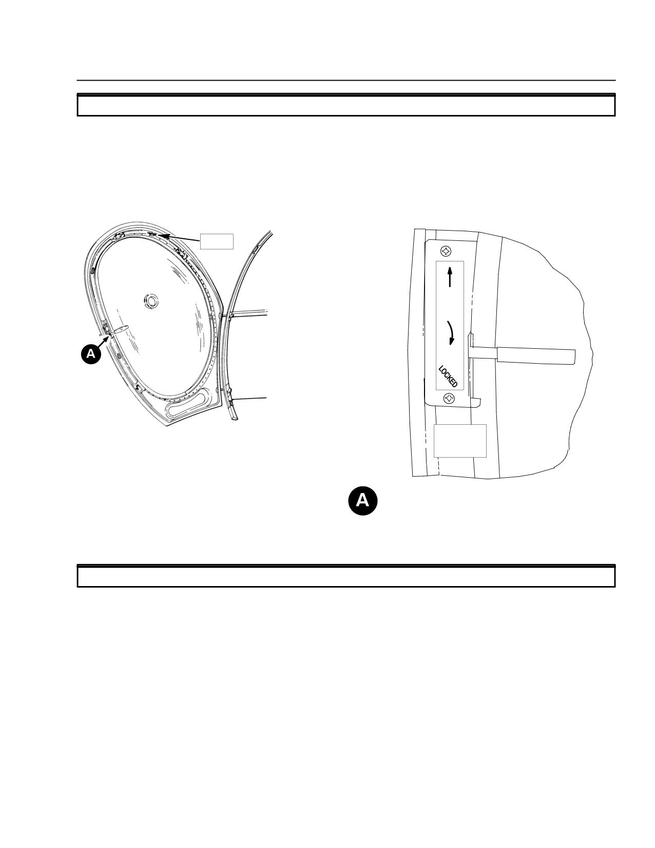
MD 500E
ROTORCRAFT FLIGHT MANUAL
CSP-E-1
(Model 369E)
Emergency and
Malfunction Procedures
3-16. EMERGENCY EGRESS
Pilot compartment doors:
Pilot doors function as primary and emergency exits.
Cabin doors:
Passenger doors function as primary and emergency exits.
EXIT
TO
OPEN
TO
LOCK
PILOT COMPARTMENT DOOR LH (TYPICAL)
PILOT/PASSENGER COMPARTMENT DOOR EXIT
F03-012
Figure 3-2. Emergency Exits
3-17. EMERGENCY EQUIPMENT
First Aid Kit:
The first aid kit is located on the right side forward edge of the pilot's seat
structure.
The kit is a commercial type containing the items necessary to render lim-
ited emergency first aid.
Fire Extinguisher:
The fire extinguisher is located on the pilot side forward door frame.
Refer to the ``FIRE'' paragraph in this section for recommended use of fire
extinguisher.
FAA Approved
Revision 17
3-27
CSP-E-1
ROTORCRAFT FLIGHT MANUAL
MD 500E
(Model 369E)
Emergency and
Malfunction Procedures
This page intentionally left blank!
FAA Approved
3-28
Revision 17
MD 500E
ROTORCRAFT FLIGHT MANUAL
CSP-E-1
(Model 369E)
Normal Procedures
S E C T I O N IV
NORMAL PROCEDURES
TABLE OF CONTENTS
PARAGRAPH
PAGE
4-1.
Preflight Requirements
4-1
Figure 4-1. Pilot's Preflight Guide
4-2
Daily Preflight Checks
4-3
Figure 4-2. Instrument Panel, LH Command - Layout Typical
4-9
Figure 4-3. Instrument Panel, RH Command - Layout Typical
4-10
Figure 4-4. Cyclic and Collective Stick Grips
4-11
4-2.
Engine Pre-Start Cockpit Check
4-12
4-3.
Engine Start
4-15
4-4.
Engine Run Up
4-17
4-5.
Before Takeoff
4-20
4-6.
Takeoff
4-22
4-7.
Cruise
4-23
4-8.
Low Speed Maneuvering
4-23
4-9.
Practice Autorotation
4-24
4-10. Doors Off Flight
4-25
4-11. Landing Approach
4-25
4-12. Running Landing
4-25
4-13. Engine/Aircraft Shutdown
4-26
4-14. Post Flight
4-28
4-15. Deceleration Check
4-28
4-16. Normal Engine Restart
4-29
4-17. Noise Impact Reduction Procedures
4-29
FAA Approved
Revision 17
4-i
CSP-E-1
ROTORCRAFT FLIGHT MANUAL
MD 500E
Normal Procedures
(Model 369E)
This page intentionally left blank!
FAA Approved
4-ii
Revision 17
MD 500E
ROTORCRAFT FLIGHT MANUAL
CSP-E-1
(Model 369E)
Normal Procedures
SECTION IV
NORMAL PROCEDURES
4-1. PREFLIGHT REQUIREMENTS
NOTE: The checks described in this Section apply to the standard configuration MD
500E and do not include certain optional equipment items. Preflight checks for
optional equipment items may be found in Section IX of this manual. If your
helicopter is equipped with STC’d items, refer to the STC holder’s flight manual
supplement.
``CHECK'' means to observe the helicopter and note any obvious damage.
Damage is defined as any condition that is not normal or not within limits.
Examples of conditions to look for are: inoperable equipment, excessive leak-
age, discoloration caused by heat, loose attachment, dents, cracks, punctures,
abrasion, chafing, galling, nicks, scratches, delamination and evidence of corro-
sion. These are the most common types of damage, however, checks should not
be limited to these items.
Further checks shall be performed before the next flight if discrepancies are
noted to determine if the aircraft is airworthy. Flight is prohibited when unrep-
aired damage exists which makes the aircraft unairworthy.
Have a thorough understanding of operating limitations. (Ref. Section II).
Service helicopter as required. (Ref. Section VII and CSP-HMI-2).
Determine that helicopter loading is within limits. (Ref. Sections II and VI).
Check helicopter performance data. (Ref. Sections V, VIII and IX).
Be sure to include a review of the appropriate flight manual
CAUTIONsupplemental data for type of optional equipment installed
(including STC items) as a regular part of preflight planning.
Perform Pilot's Daily Preflight Check prior to the first flight of the day.
Perform Pilot's Preflight Check prior to subsequent flights that same day.
Brief passengers on relevant operational procedures and associated hazards
(Ref. Sec. I, Pilot's Briefing).
FAA Approved
Revision 13
4-1
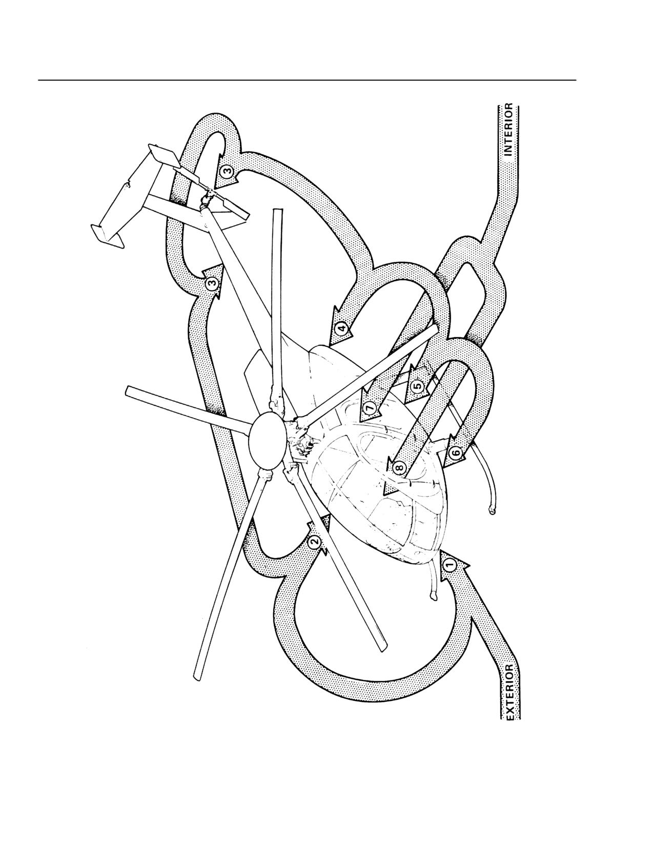
CSP-E-1
ROTORCRAFT FLIGHT MANUAL
MD 500E
Normal Procedures
(Model 369E)
F03-013
Figure 4-1. Pilot’s Preflight Guide
FAA Approved
4-2
Revision 13
MD 500E
ROTORCRAFT FLIGHT MANUAL
CSP-E-1
(Model 369E)
Normal Procedures
DAILY PREFLIGHT CHECKS
PRELIMINARY CHECKS
F
Fuel cell drain valve - take sample (Start pump OFF)
CHECK FOR
CONTAMINANTS
F
Anti-ice fuel filter drain valve (if installed) take sample
CHECK FOR
(Start pump ON)
CONTAMINANTS
Do not open fuel filter drain valve unless start pump is ON. An
WARNING
unexpected flameout or power loss may occur if air is allowed to
enter the fuel system.
EXTERIOR
FUSELAGE - FORWARD END
F
Aircraft tiedowns and covers
REMOVED
F
Aircraft attitude for weak or damaged landing gear
CHECK
dampers
F
Canopy for condition and cleanliness
CHECK
F
OAT thermometer sun shield
CHECK
F
Fresh air vent
NO OBSTRUCTIONS
F
Pitot tube
NO OBSTRUCTIONS
F
Tail rotor pedals for condition and
CHECK
security of quick-release pins (both sides with dual
controls)
F
Landing light and anticollision light
CHECK
FAA Approved
Revision 13
4-3
CSP-E-1
ROTORCRAFT FLIGHT MANUAL
MD 500E
Normal Procedures
(Model 369E)
FUSELAGE - RH SIDE
F
Skid, strut fairings, strut cuffs
CHECK
F
Position light, skid tip
CHECK
F
Fuel tank vent
NO OBSTRUCTIONS
F
Fuselage skin
CHECK
F
Passenger steps for condition and security
CHECK
F
Passenger and cargo doors condition and latching
CHECK
F
M/R transmission oil level
CHECK
F
M/R transmission oil filter bypass indicator (if installed)
CHECK
F
Fuel level; cap security
CHECK
F
Engine oil level; cap security
CHECK
NOTE: Oil level should be checked within 15 minutes after shutdown.
F
Overhead canopy for condition and cleanliness
CHECK
F
Main rotor hub, pitch control rods, blade dampers,
CHECK
swashplate and mast
F
Lead-lag link attach nuts for cracks
CHECK
F
Main rotor blades for chordwise cracks on the underside of
CHECK
the blade skin and doubler. If existing, the cracks will be at
the leading and trailing edges of the root fitting in the area
of the two most outboard bolts or outermost end of lower
root fitting.
F
Oil cooler air inlet
NO OBSTRUCTIONS
F
Engine air inlet/plenum chamber
NO OBSTRUCTIONS
OR FOREIGN
OBJECTS
When the helicopter has been parked outside during falling or
CAUTIONblowing snow, remove accumulated ice and snow from engine inlet
area and all helicopter exterior surfaces. Also open plenum
chamber access door and visually determine that the inlet screen
or particle separator (if installed) has not become clogged with
ice and snow.
F
Static port
NO OBSTRUCTIONS
F
All inspections doors/panels
SECURED
FAA Approved
4-4
Revision 17
MD 500E
ROTORCRAFT FLIGHT MANUAL
CSP-E-1
(Model 369E)
Normal Procedures
TAILBOOM/TAIL ROTOR
F
Tailboom
CHECK: NO DAMAGE
ALLOWED
F
Position and anti collision lights
CHECK
F
Stabilizers (vertical, horizontal and end plates)
CHECK: NO DAMAGE
ALLOWED
F
Tail skid
CHECK
F
Tail rotor gearbox attachment to tailboom for security and
CHECK
condition
F
Chip detector and wiring
CHECK
F
Control push-pull rod and bellcrank
CHECK
F
Tail rotor transmission oil level
CHECK
F
Output shaft dust cover, retainer nut, tang washer, rubber
CHECK
bumper.
Check for torque stripe paint across retainer nut, tang washer, and
CAUTIONfork assembly. If torque stripe on nut and tang washer is not in
line with stripe on drive fork, the tang washer inner key tang may
be sheared. Advise maintenance.
F
Tail rotor drive fork conical bearings (if installed):
F F
Pivot tail rotor hub and fork through full range of travel
CHECK
and check for axial play between the conical bearing
inner and outer races. No play is allowed.
F
Tail rotor drive fork elastomeric bearings (if installed):
NOTE: Check bearing for general condition. Elastomeric bearings are suspected of
being unserviceable if rubber deterioration or separation, or a vibration is noted.
Evidence of light swelling, pock marks and crumbs are surface conditions and
are not indications of bearing failure.
F F
Apply teetering force by hand to tail rotor blades
CHECK
(stop-to-stop). Check for fork-to-bearing bond failure.
Failure is indicated by any motion between outer
bearing cage and fork (bearing turns in fork).
F F
Teeter blades stop-to-stop. Observe four radial molded
CHECK
ridges on each bearing as teetering takes place. If ridges
assume continuous curved shape, bearings are intact.
Discontinuity in molded ridges indicates bearing failure.
F
Tail rotor pitch bearing
F F
Hold tail rotor hub firmly and check lead-lag play at tip
CHECK FOR WEAR
of each blade. Play in excess of approximately 0.25 in.
on either blade may not be acceptable.
F
Tail rotor blades and pitch links
CHECK
FAA Approved
Revision 15
4-5
CSP-E-1
ROTORCRAFT FLIGHT MANUAL
MD 500E
Normal Procedures
(Model 369E)
NOTE: Visually check each tail rotor blade abrasion strip for evidence of debonding
along the abrasion strip/airfoil bond line.
F
Tail rotor drive shaft coupling
CHECK: NO DAMAGE
ALLOWED
F F
Rock tail rotor back and forth in plane of rotation and check main rotor blades
for coincidental movement.
NOTE: If tail rotor blade tip can move in excess of 3/4 inch (1.9 cm) without coincidental
movement of the main rotor blades, inspect tail rotor drive shaft couplings in
accordance with the Handbook of Maintenance Instructions.
F
Main rotor blades for condition and abrasion strip for
CHECK
condition and bonding (do not handle trim tabs)
F
Overrunning clutch (turn main rotor blade forward then aft) CHECK
F
All inspection panels
SECURED
ENGINE COMPARTMENT
F
Engine mounts, mounting pads, and firewalls
CHECK
F
Landing gear attach points, rear dampers (leaks and
CHECK
inflation)
F
Engine oil, air, and fuel lines
CHECK
F
Scavenge oil filter bypass indicator (if installed)
CHECK
F
Fuel filter bypass indicator (C20R/2 SP only)
CHECK
F
Engine electrical connections
CHECK
F
Generator control unit circuit breakers (2) (generic wire
CHECK
harness only)
F
Fuel control, N2 governor, and associated linkages
CHECK
F
Exhaust ducts
CHECK
F
Engine compartment doors for condition and security
CHECK
FUSELAGE - LH SIDE
F
Skid, strut fairings; strut cuffs
CHECK
F
Position light, skid tip
CHECK
F
Pilot and cargo doors - condition and latching
CHECK
F
Passenger steps for condition and security
CHECK
F
Fuselage skin
CHECK
FAA Approved
4-6
Revision 13
//////////////////////////