Helicopter MD 500E. Flight Manual (1982-2011) - page 2
MD 500E
ROTORCRAFT FLIGHT MANUAL
CSP-E-1
(Model 369E)
Normal Procedures
F
Overhead canopy
CHECK
F
Battery compartment vent
NO OBSTRUCTIONS
FUSELAGE - UNDERSIDE
F
Fuselage skin
CHECK
F
Fuel tank and other vents
NO OBSTRUCTIONS
F
Cargo Hook (if installed)
CHECK (REF.
SECTION IX)
F
Antennas
CHECK
INTERIOR
AFT COMPARTMENT
F
Impeller belt
CHECK
F
Fuel cell access doors
SECURED
F
Controls access door
SECURED
F
Loose equipment or cargo
SECURED
F
Seats, seat belts, and shoulder harness
CHECK
F
Compartment doors closed and latched
CHECK
NOTE: Refer to Paragraph 4-10 if planning doors off flight.
FORWARD COMPARTMENT
F
Battery compartment
CHECK
F
Fire extinguisher and first aid kit
CHECK
F
Loose equipment or cargo
CHECK
NOTE: Refer to Paragraph 4-10 if planning doors off flight.
F
Seats, seat belts, and shoulder harness
CHECK
F
Interior and exterior lights (all switches OFF after check)
CHECK
F
Compartment doors closed and latched
CHECK
FAA Approved
Revision 15
4-7
CSP-E-1
ROTORCRAFT FLIGHT MANUAL
MD 500E
Normal Procedures
(Model 369E)
PREFLIGHT CHECKS
Perform these checks prior to subsequent flights of the same day.
F Fluid levels
CHECK
F Engine compartment - fluid leaks and
CHECK
bypass indicators
F Air inlet screens/particle separator
CHECK
F Fuel cap, access doors and panels
CHECK
F Main rotor blades
CHECK
F Tailboom and empennage
CHECK
F Tail rotor rotor blades
CHECK
F Cargo and loose equipment
CHECK
F Crew and cabin doors
CHECK
FAA Approved
4-8
Revision 13
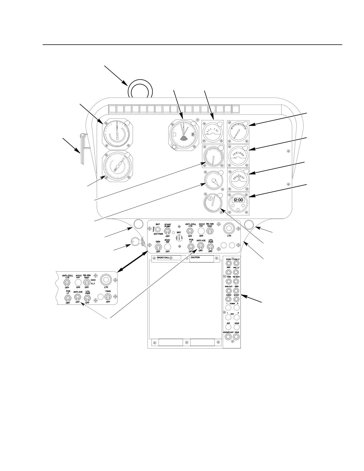
MD 500E
ROTORCRAFT FLIGHT MANUAL
CSP-E-1
(Model 369E)
Normal Procedures
ENGINE OUT AUDIBLE
WARNING HORN
(SEE NOTE)
ENGINE OIL
TEMPERATURE
ALTIMETER
INDICATOR
AIRSPEED
INDICATOR
ENGINE OIL
PRESSURE
INDICATOR
VNE
AL
T
FUEL
PLACARDS
QUANTITY
INDICATOR
AMMETER
CLOCK
DUAL TACHOMETER
TORQUE
INDICATOR
TURBINE OUTLET
TEMPERATURE
FUEL
PULL
VALVE
FOR
(TOT) INDICATOR
AIR
FRESH AIR
FUEL SHUTOFF
VENT
VALVE
N1
TACHOMETER
KEY
SWITCH
EDGE LIGHTED SWITCH
PANEL: PRE AND LATE
GENERIC
EDGE LIGHTED CIRCUIT
BREAKER PANEL
EARLY GENERIC
ANTI-ICE
SWITCH
(250-C20R/2)
NOTE:
ON LATER MODEL 369E HELICOPTERS,
F03-014-1
ENGINE OUT AUDIBLE WARNING HORN
RELOCATED ADJACENT TO PILOT’S
UTILITY LIGHT ON MAP CASE PANEL
Figure 4-2. Instrument Panel, LH Command - Layout Typical
FAA Approved
Revision 13
4-9
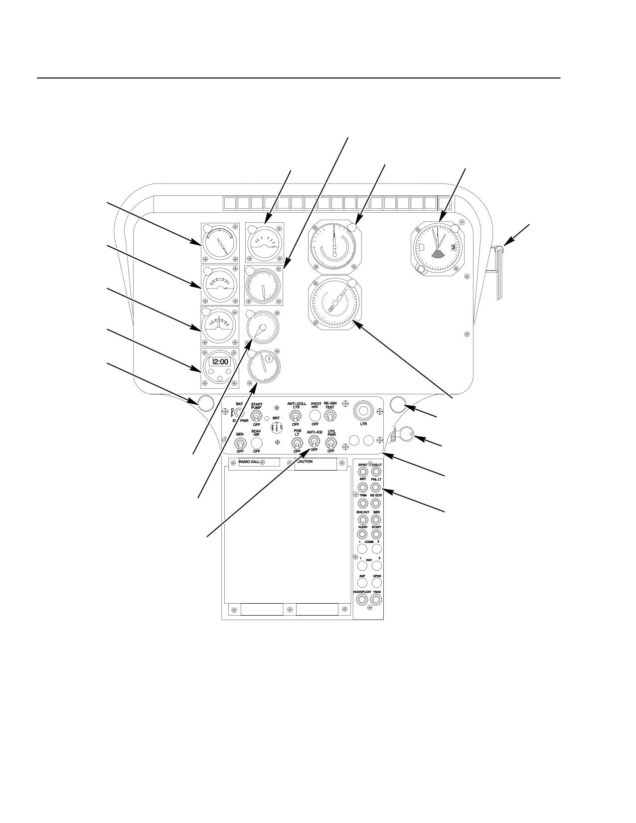
CSP-E-1
ROTORCRAFT FLIGHT MANUAL
MD 500E
Normal Procedures
(Model 369E)
TORQUE
INDICATOR
ENGINE OIL
AIRSPEED
TEMPERATURE
ALTIMETER
INDICATOR
INDICATOR
ENGINE OIL
PRESSURE
INDICATOR
VNE
PLACARDS
FUEL
QUANTITY
AL
T
INDICATOR
AMMETER
CLOCK
FUEL SHUTOFF
VALVE
VALVE
PULL
AIR
DUAL TACHOMETER
FRESH AIR
VENT
KEY
SWITCH
TURBINE OUTLET
TEMPERATURE
EDGE LIGHTED SWITCH
(TOT) INDICATOR
PANEL
N1 TACHOMETER
EDGE LIGHTED CIRCUIT
BREAKER PANEL
ANTI-ICE
SWITCH
(250-C20R/2)
F03-014-2
Figure 4-3. Instrument Panel, RH Command - Layout Typical
FAA Approved
4-10
Revision 13
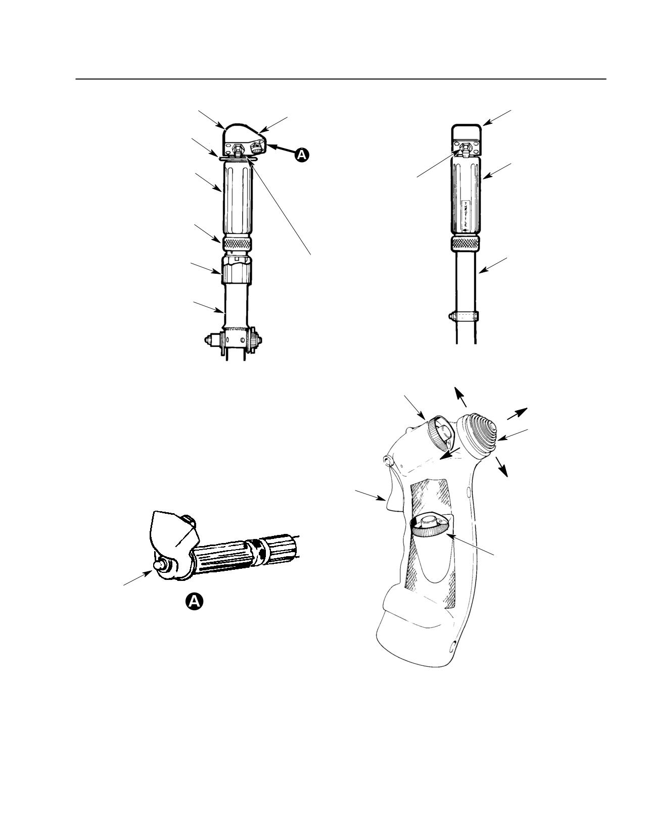
MD 500E
ROTORCRAFT FLIGHT MANUAL
CSP-E-1
(Model 369E)
Normal Procedures
SWITCH HOUSING
SWITCH HOUSING
LANDING LIGHT
SWITCH
IDLE RING
COPILOT’S
TWIST GRIP
PILOT’S THROTTLE
GOVERNOR
TWIST GRIP
INCREASE/DECREASE
SWITCH
THROTTLE
TWIST GRIP
FRICTION NUT
GOVERNOR
COPILOT’S
COLLECTIVE
INCREASE/DECREASE
COLLECTIVE
STICK FRICTION NUT
SWITCH
(OPTIONAL)
PILOT’S
COLLECTIVE STICK
CARGO HOOK
DWN
RELEASE (OPTION)
R
CYCLIC TRIM
SWITCH
L
UP
ICS/COMM
TRIGGER
FLOAT INFLATE
SWITCH (OPTION)
START
BUTTON
PILOT’S
COLLECTIVE
F03-015
Figure 4-4. Cyclic and Collective Stick Grips
FAA Approved
Revision 13
4-11
CSP-E-1
ROTORCRAFT FLIGHT MANUAL
MD 500E
Normal Procedures
(Model 369E)
4-2. ENGINE PRE-START COCKPIT CHECK
ELECTRICAL POWER - OFF
F
All cabin doors CLOSED AND SAFELOCKED
CHECK
F
Tail rotor pedals
ADJUST
NOTE: Adjust pedal position to insure that the pedals can be moved throughout the
entire range of travel.
F
Tail rotor pedal lock pins
SECURED
F
Seat belt and shoulder harness for proper fit and
FASTENED
engagement of buckle
NOTE: Insure center seat shoulder harness crosses over center of body.
F
Operation of shoulder harness inertia lock
CHECK
F
Cyclic, collective (friction off) and pedals
FULL TRAVEL
F
Cyclic stick
NEUTRAL, FRICTION
ON
NOTE: Cyclic stick longitudinal neutral position is about 35 percent (1/3) travel from full
aft; lateral position may be determined by centering the friction control knob in
the guide link.
F
Tail rotor pedals
CENTERED
F
Collective stick
FULL DOWN
FRICTION ON
F
Landing light
OFF
F
Air filter bypass control handle (if installed)
CHECK SECURITY
AND POSITION
F
Rotor brake handle (if installed)
STOWED
F
Cabin heat (if installed)
OFF
F
Engine anti-ice (Allison 250-C20B)
OFF
F
Magnetic compass heading
CHECK
F
VNE card
SELECT
F
Static position of all instruments
CHECK
FAA Approved
4-12
Revision 13
MD 500E
ROTORCRAFT FLIGHT MANUAL
CSP-E-1
(Model 369E)
Normal Procedures
F
Altimeter
SET
F
All electrical switches
OFF
F
Radio switches
OFF
F
Circuit breakers
IN
F
Fuel shutoff valve
OPEN (IN)
Attempting to start the engine with any bleed air devices ON, may
CAUTION
result in a ‘‘Hot start’’.
ELECTRICAL POWER - ON
F
Electrical power: Battery or external power start
F F
BAT/EXT switch: set to BAT for battery start; to EXT
AS REQUIRED
for external power start
F F
If used, connect GPU.
NOTE: Minimum capacity 20V dc with 500 amp load.
Maximum capacity 28.5V dc with 500 amp load.
F
Lights
AS REQUIRED
F
Key switch
ON
F
Engine Out Warning System/Auto Reignition System Checks
F F
Pre-Generic and Late Generic Configurations:
NOTE: See Section I and Figure 4-2 to determine which version of the electrical system
is installed in the aircraft.
F F F
GEN switch ON then OFF to check audible engine out warnings (both
external horn in the cabin and internal within the ICS system).
F F F
Hold RE-IGN TEST switch in the TEST position. Verify the RE-IGN
caution light illuminates and the sound of the engine ignitor firing is heard.
Release the RE-IGN TEST switch.
F F F
Press the RE-IGN caution light to reset (extinguish) the light. (Pre-generic
configuration only)
FAA Approved
Revision 13
4-13
CSP-E-1
ROTORCRAFT FLIGHT MANUAL
MD 500E
Normal Procedures
(Model 369E)
F F
Early Generic Configuration:
F F F
Place the Reignition Test switch in the GND TEST position (full up). Verify
that the ENGINE OUT warning and RE-IGN caution lights illuminate, the
audible engine out warnings activate (both external horn in the cabin and
internal within the ICS system), and the sound of the ignitor firing is heard.
F F F
Return test switch to OFF
F
Fuel gauge
CHECK READING
F
All other instruments
CHECK
F
XMSN OIL PRESS, ENG OUT, and GEN warning/caution
ON
lights
F
Press-to-test caution and warning lights
CHECK
F F
Caution light dim switch
CHECK
NOTE: BAT 140° and RE-IGN P RST caution lights do not dim. All other caution lights
will return to bright when power is removed and restored by cycling the BAT
switch or pulling and resetting the PNL LT circuit breaker.
F
Cyclic trim control check:
F F
Momentarily motor cyclic trim control forward, left,
OPERATE
right, aft (listen for motor actuation)
F
Twistgrip to FULL OPEN, return to GROUND IDLE STOP, CHECK
then to CUTOFF position.
FAA Approved
4-14
Revision 13
MD 500E
ROTORCRAFT FLIGHT MANUAL
CSP-E-1
(Model 369E)
Normal Procedures
4-3. ENGINE START
F
Cyclic stick - trimmed neutral; friction ON
RECHECK
Do not attempt engine start with cyclic stick in positions other than
CAUTION
neutral. Damage to rotor head and controls will result.
F
Collective stick - full down; friction on
RECHECK
F
Twistgrip - CUTOFF position
RECHECK
F
Generator switch OFF
RECHECK
A hot start may result if the GEN switch is left in the ON position.
CAUTION
(Early Generic Configuration Only)
F
Start pump
AS REQUIRED
NOTE: Start pump required when using alternate or emergency fuel (Ref. to Section II).
F
Rotors
CLEARED
F
Start/ignition button
PRESS AND HOLD
NOTE: Starter time limits are: 1 minute ON, 1 minute OFF; 1 minute ON, and 23 minutes
OFF.
F
Rotate twistgrip to ground idle for ignition when N1 indicates 12 to 15 percent (see
Section II, Minimum N1 Speed Starting Recommendations Placard).
NOTE: Peaking of N1 below 15 percent may occur during cold weather starting
conditions. Under these conditions, a start may be attempted at a minimum of
12 percent N1. GPU starts are recommended when normal cranking speed
cannot be obtained by using the battery.
FAA Approved
Revision 13
4-15
CSP-E-1
ROTORCRAFT FLIGHT MANUAL
MD 500E
Normal Procedures
(Model 369E)
During starts, overtemperatures above 810°C for 10 seconds or
CAUTION
less with a momentary peak at 927°C for not more than 1 second are
permitted. Consult Rolls Royce Operation and Maintenance Manu-
al if these limits are exceeded.
ABORT START IF:
1. An immediate temperature rise is not observed on the TOT indi-
cator.
2. No indication of engine oil pressure is observed.
3. Main rotor is not rotating by 25 percent N1 (Refer to Allison Op-
eration and Overhaul Manual.)
4. A zero or positive indication is observed on ammeter (this may
indicate a failure in the starting circuit that may de-energize the
starter creating conditions favorable for a hot start).
F
Abort start procedures:
F F
Close twistgrip to the cutoff position.
F F
Use starter to continue motoring engine for at least ten seconds or until TOT
decreases below 150°C.
F
Start/ignition button - release at 58 to 60 percent N1
RELEASE
F
Engine oil pressure 50 to 130 psi
CHECK
NOTE: During cold weather operation, 150 psi oil pressure is allowable following an
engine start. Remain at ground idle RPM until normal oil pressure limits are
attained.
F
All caution and warning indicators out
CHECK
NOTE: Transmission oil pressure warning (XMSN OIL PRESS) indicator will go out
within 30 seconds from engine light-off for 369D25100 series transmissions, or
within 60 seconds for 369F5100 transmissions. The auto reignition ARMED light
ON; GEN OUT indicator will remain on until the generator switch is moved to the
GEN position.
The reignition indicator may illuminate when the transmission warning light goes
out. After ground idle RPM is attained, press the RE-IGN light to reset.
F
Engine idle speed - 64 to 65 percent N1
CHECK
During engine operation at ground idle, keep pedals centered. Ped-
CAUTION
al bungee will tend to depress left pedal, thereby decreasing N2/NR
speed.
FAA Approved
4-16
Revision 14
MD 500E
ROTORCRAFT FLIGHT MANUAL
CSP-E-1
(Model 369E)
Normal Procedures
F
All other engine instruments
CHECK
F F
N2 engine and rotor rpm indicators for superimposed needles.
Malfunctions are indicated if rotor and engine rpm indicator
CAUTION
needles are not superimposed. Shut down engine if this condition
exists.
NOTE: ‘‘Superimposed’’ means within 1/2 a needle width. The relative positions of the
superimposed needles should remain constant during powered flight.
F
Start pump
AS REQUIRED
4-4. ENGINE RUN UP
NOTE: Refer to Section II “Power turbine (N2) speed avoid range”.
Avoid continuous operation of engine between 90 and 98 percent N2 if Allison
AD 83-03-02 has not been complied with (250-C20B only).
NOTE: Checks with an asterisk (:) need only be performed prior to the first flight of the
day. Insure that an “Auto Reignition Check” is performed prior to flying into falling
or blowing snow.
F
Electrical power
SELECT
F F
BAT/EXT switch
SELECT ‘‘BAT’’
F F
External power start
DISCONNECT GPU
F
Set generator (GEN) to ON (GEN OUT caution light out;
OPERATE AND
ammeter will show charge)
CHECK
NOTE: Monitor N1 and TOT when turning generator switch ON.
If N1 decays below 60 percent or TOT approaches 810°, turn generator OFF and
increase N1 speed with twistgrip to 70 percent, then reset generator to ON.
During the initial recharging period after a battery start, electrical loads may
exceed 150 amps for a short period of time (2 minute limit). The electrical load
should be less than 150 amps prior to takeoff or activation of any additional
electrical equipment.
F
Avionics (as required)
ON AND CHECK
F
Cyclic friction
RELEASE AND SET
AS DESIRED
FAA Approved
Revision 16
4-17
CSP-E-1
ROTORCRAFT FLIGHT MANUAL
MD 500E
Normal Procedures
(Model 369E)
F
Twistgrip
FULL OPEN
Check for unusual aircraft vibration or noise while accelerating
CAUTION
from ground idle to flight idle. If any unusual vibration or noise oc-
curs, this may be an indication of a loose or defective tailrotor dirve-
shaft damper. Shut aircraft down and advise maintenance.
CAUTION
Avoid rapid acceleration when parked on slippery surfaces.
NOTE: If the engine has been shut down for more than 15 minutes, stabilize at idle for
1 minute before increasing power.
:ENGINE CONTROLS/ENGINE OUT AND
LOW ROTOR WARNING/AUTO REIGNITION CHECKS
NOTE: Whenever there is transmission oil pressure the auto-reignition system is
armed.
F
Press reignition (RE-IGN P RST) light
LAMP OUT
F
N2 high beep range - 104% to 105%
CHECK
F
N2 low beep range - 98% or less
CHECK
F
Low rotor warning - on at 98 ± 1%
CHECK
NOTE: ENGINE OUT light only - no audio horn (early generic configuration).
ENGINE OUT light and audio horn (pre-generic and late generic).
F
RE-IGN P RST indicator light
ON
F
Set N2 to 102%
ESTABLISH
F
Press reignition (RE-IGN P RST)
LAMP OUT
Pulling the engine out warning system circuit breaker will disarm
CAUTION
the auto reignition and engine out/low rotor warning systems.
FAA Approved
4-18
Revision 13
MD 500E
ROTORCRAFT FLIGHT MANUAL
CSP-E-1
(Model 369E)
Normal Procedures
:ENGINE BLEED AIR SYSTEMS CHECKS
F
CABIN HEAT (if installed) - ON - Observe 30-40°C
CHECK TOT
increase in TOT, then OFF.
INCREASE/
DECREASE
F
Engine ANTI-ICE ON - Observe increase 10-20°C in TOT, CHECK TOT
then OFF.
INCREASE/
DECREASE
F
SCAV-AIR Switch ON (if installed) observe slight rise in
CHECK TOT
TOT (about 5°C).
INCREASE AND SET
SWITCH AS DESIRED
NOTE: If no increase in TOT is observed, operation of the scavenge air system may be
checked by verifying that the flapper door (scavenge air outlet) is open.
:THROTTLE RIGGING CHECK
NOTE: If the flight will involve rolling the twistgrip to the ground idle position while
airborne (Autorotation training, maintenance test flight, etc.) this check must be
performed even thought it may not be the first flight of the day.
F
N2 102%
RECHECK
F
Pilot's twistgrip
SNAP TO IDLE
If engine flames out, do not try to recover by opening twistgrip.
CAUTION
Close twistgrip to CUTOFF and monitor TOT.
F
If engine flames out, refer to the HMI for proper throttle control rigging.
F
If dual controls are installed, repeat procedure using
RECHECK
copilot's twistgrip.
F
Twistgrip
FULL OPEN
F
N2 - 102%
RECHECK
FAA Approved
Revision 13
4-19
CSP-E-1
ROTORCRAFT FLIGHT MANUAL
MD 500E
Normal Procedures
(Model 369E)
4-5. BEFORE TAKEOFF
F
All caution and warning lights out
RECHECK
F
Engine oil pressure - 90 to 130 psi
RECHECK
F
Ammeter
CHECK READING
NOTE: Ammeter reading will fluctuate slightly when anti-collision lights are on.
F
All cabin doors closed and safelocked
RECHECK
F
Cabin heat
AS DESIRED
NOTE: Hover performance is reduced with cabin heat ON (Ref. Sections V and VIII).
F
Collective control friction
RELEASE AND
SET AS DESIRED
When removing collective friction, be alert for abnormal collective
WARNING
loads that would cause the collective to raise by itself.
F
Cyclic response check:
F F
With collective pitch full down, gently move cyclic stick
CHECK
and observe rotor tip for correct movement and track
F
All instruments in the green
CHECK
F
Position and anti collision lights
AS REQUIRED
F
SCAV AIR (if installed)
AS DESIRED
NOTE: Air filtration is improved with SCAV-AIR on, however, hover performance is
reduced (Ref. Sections V, and VIII).
F
Pitot Heat (if installed)
AS REQUIRED
FAA Approved
4-20
Revision 13
MD 500E
ROTORCRAFT FLIGHT MANUAL
CSP-E-1
(Model 369E)
Normal Procedures
F
Engine ANTI-ICE:
AS REQUIRED
F F
Use engine ANTI-ICE when OAT is below 5°C (41°F) and visible moisture is
present.
F F
Check for TOT increase when turning anti-ice ON
NOTE: Hover performance is reduced with ANTI-ICE ON (Ref. Sections V and VIII).
F
Optional inflight test of the auto-reignition/engine out warning
system: (Early Generic Configuration Only):
NOTE: See Section I and Figure 4-2 to determine which version (‘‘early generic” / ‘‘late
generic”) of the generic wire harness is installed in the aircraft.
This check may be performed at the pilot’s discretion.
F F
Prior to takeoff:
F F F
While on the ground at 102-103% N2, place RE-IGN test switch in the FLT
(middle) position. RE-IGN and ENGINE OUT lights should illuminate.
F F F
Bring the aircraft to a hover and observe actuation of the engine out audible
warnings.
NOTE: If audible warnings are not heard, this indicates a possible rigging problem with
the air/ground switch. Refer to applicable maintenance instructions for
adjustment.
F F F
Land helicopter and return RE-IGN test switch to OFF and press RE-IGN
light to reset system.
FAA Approved
Revision 13
4-21
CSP-E-1
ROTORCRAFT FLIGHT MANUAL
MD 500E
Normal Procedures
(Model 369E)
F F
While in cruise:
F F F
Place RE-IGN test switch in FLT position.
F F F
RE-IGN and ENGINE OUT lights should illuminate along with the
ENGINE OUT audible warning.
F F F
Return RE-IGN test switch to OFF.
F F F
Press RE-IGN light to reset system.
4-6. TAKEOFF
NOTE: For takeoff in noise-sensitive areas, refer to paragraph 4-17 for noise impact
reduction procedures.
F Determine that hover area and takeoff path are clear.
F Follow normal helicopter takeoff procedure with N2 set at 103 percent.
NOTE: Governed N2 rpm should increase 1/2 to 1 percent on takeoff - adjust as
necessary to maintain N2 at 103 percent.
F Follow recommended takeoff profile shown in Height Velocity Diagram (Ref.
Section V).
If sudden unusual or excessive vibrations should occur during
WARNING
flight, a precautionary landing should be made. No further flights
shall be attempted until the cause of the vibration has been
identified and corrected.
NOTE: Momentary fluctuation in indicated airspeed may occur during acceleration and
climbout. This fluctuation is characterized by a rapid rise in indicated air speed
to approximately 40 knots, followed by a drop back to 30 knots and then normal
increase as determined by the rate of acceleration. Maintain recommended
takeoff profile to minimize fluctuation. Indicated airspeed is unreliable when
climbing at less than 40 knots IAS.
F Use Cyclic trim as desired to minimize stick forces.
NOTE: Proper longitudinal trim is established when small fore and aft cyclic movements
require the same force.
FAA Approved
4-22
Revision 13
MD 500E
ROTORCRAFT FLIGHT MANUAL
CSP-E-1
(Model 369E)
Normal Procedures
4-7. CRUISE
F Cyclic trim: use proper trimming procedures described for climbout.
F
SCAV AIR (if installed)
AS DESIRED
F Above 50 knots and 50-foot altitude above terrain, select N2 between 102
and 103 percent for best comfort level.
F Use engine anti-icing when OAT is below 5°C (41°F) and visible moisture
conditions prevail.
4-8. LOW SPEED MANEUVERING
F Maneuvers that exceed thrust capability of the tail rotor should be avoided.
NOTE: Conditions where thrust limits may be approached are: High density altitude,
high gross weight, rapid pedal turns, and placing the helicopter in a down wind
condition. These conditions may exceed the thrust capability of the tail rotor.
F Extreme aircraft attitudes and maneuvers at low speeds should be avoided.
Uncoordinated turns/maneuvers may cause fuel starvation with
WARNING
less than 35 pounds of fuel on board.
Observe the cross-hatched regions of Height Velocity Diagram
WARNING
(Ref. Section V). These represent airspeed/altitude combinations
from which a successful autorotation may be difficult to perform.
Operation within the cross hatched area in not prohibited, but
should avoided.
FAA Approved
Revision 13
4-23
CSP-E-1
ROTORCRAFT FLIGHT MANUAL
MD 500E
Normal Procedures
(Model 369E)
4-9. PRACTICE AUTOROTATION
Perform throttle rigging check prior to attempting practice
WARNING
autorotations (paragraph 4-4). Misrigging of the throttle control
may result in inadvertent flameout during rapid closing of the
twistgrip to the ground idle position.
Uncoordinated turns/maneuvers may cause fuel starvation with
less than 35 LBS of fuel. Do not practice autorotations if the FUEL
LEVEL LOW caution indicator is ON.
Do not perform intentional full touchdown autorotation with blade
CAUTION
tracking reflectors installed on blade tips.
Make practice autorotation landings as follows:
For autorotation descent, the twistgrip should be in the full open or ground
idle position. However, if a practice autorotation landing (minimum engine
power) is desired, rotate the twistgrip to the ground idle position.
Increase collective pitch after establishing autorotation to prevent rotor
overspeed if flight is at high gross weight or high density altitude. To re-
duce rate of descent or to extend gliding distance, operate at minimum rotor
rpm. Restore ROTOR RPM (NR) by lowering collective prior to flareout.
If a power recovery is desired, lower collective to full down, rotate the
twistgrip to the full open position, verify that N2 is between 102 and 103
percent and that full engine power is available prior to increasing collective.
Conduct practice autorotation at 130 knots IAS or below (see VNE placards).
Maintain rotor between 420 and 523 by use of the collective control.
NOTE: Keeping the rotor above 420 RPM will place the engine above the N2 speed
avoid range.
Refer to Section II “Power turbine (N2) speed avoid range”.
CAUTION
Maximum gliding distance is obtained at 80 knots and 410 rotor rpm.
Minimum rate of descent is obtained at 60 knots and 410 rotor rpm.
NOTE: Glide distances attained during an actual engine out autorotation may be less
than the glide distances achieved during practice autorotations when operating
at reduced RPM (N2/NR needles joined).
Touchdown in a level attitude.
Avoid use of aft cyclic control or rapid lowering of collective pitch during
initial ground contact or during ground slide.
FAA Approved
4-24
Revision 17
MD 500E
ROTORCRAFT FLIGHT MANUAL
CSP-E-1
(Model 369E)
Normal Procedures
Autorotation RPM:
Normal rotor RPM (collective fully down) is 485±5 RPM at 2250 pounds
gross weight at sea level, 60 knots. Rotor speed will decrease approximately
10 RPM for each 100 pound reduction in gross weight and increase approxi-
mately 6.5 RPM for each 1000 foot increase in density altitude. For gross
weights greater than 2250 pounds, increase collective control as required to
maintain approximately 485 RPM.
4-10. DOORS OFF FLIGHT
Doors off flight is permitted in accordance with the restrictions noted in Sec-
tion II.
Any object that is not properly secured may exit the aircraft
WARNING
during flight.
Items secured with Velcro (i.e., first aid kit, seat cushions) should
not be considered properly secured.
Secure or stow in the baggage compartment all loose equipment.
Secure or remove unoccupied seat cushions.
Use ear protection.
4-11. LANDING APPROACH
Set N2 at 103 percent.
Set SCAV-AIR (if installed) as desired.
4-12. RUNNING LANDING
Maximum recommended ground contact speed is 30 knots for smooth hard sur-
face.
Avoid rapid lowering of the collective after ground contact.
Avoid the use of aft cyclic after ground contact.
FAA Approved
Revision 13
4-25
CSP-E-1
ROTORCRAFT FLIGHT MANUAL
MD 500E
Normal Procedures
(Model 369E)
4-13. ENGINE/AIRCRAFT SHUTDOWN
Care should be taken when rotating the twistgrip to the ground idle
CAUTION
position and from ground idle to the cutoff position if the helicopter
is parked on a icy or slippery surface (helicopter may spin in direc-
tion of main rotor blade rotation).
NOTE: Shut down the engine before exiting the helicopter unless safety or operational
considerations dictate otherwise.
F
Pilot's twistgrip
PERFORM
DECELERATION
CHECK
NOTE: To insure proper engine performance, perform the deceleration check during
shut down after the last flight of the day (see paragraph 4-15).
F
Twistgrip to GROUND IDLE detent - hold for 2 minutes
SET
F
Collective stick
FULL DOWN
FRICTION ON
F
Cyclic stick (neutral position - approximately
TRIM TO NEUTRAL
1/3 from full aft)
APPLY FRICTION
F
All unnecessary bleed air and electrical
OFF
equipment
F
Pedals (maintain until rotor has stopped)
CENTERED
F
Twistgrip from GROUND IDLE to CUTOFF position
SET
NOTE: Immediately after closing twistgrip to the CUTOFF position, a dual tachometer
needle split should occur with NR lagging behind N2. If no needle split occurs,
check overrunning clutch for proper operation per HMI.
To ensure throttle cutoff, hold twistgrip in cutoff position until N1 decelerates to
zero and TOT is stabilized. Check for TOT decrease.
An afterfire (recognized by a rapid increase in TOT) can occur dur-
CAUTION
ing shutdown if fuel cutoff is not complete. If an afterfire occurs, im-
mediately engage the starter and motor the engine to minimize the
temperature encountered. To extinguish the fire, continue motor-
ing the engine with the twistgrip in the CUTOFF position and pull
out the fuel shutoff valve. Observe TOT limits.
FAA Approved
4-26
Revision 13
MD 500E
ROTORCRAFT FLIGHT MANUAL
CSP-E-1
(Model 369E)
Normal Procedures
NOTE: If thumping or a rapping sound is heard from the drive train during the final
revolution of the main rotor, inspect the tail rotor drive shaft couplings in
accordance with the HMI.
F
Engine out warning at 55 percent N1
CHECK
NOTE: Early Generic Configuration: ENG OUT light only - no audio .
Pre-Generic and Late Generic Configuration: ENGINE OUT light and audio
horn .
See Section I and Figure 4-2 to determine which version of the generic wire
harness is installed in the aircraft.
F
Auto reignition light
ON
Do not use collective pitch to slow rotor.
CAUTION
F
Generator switch
OFF
F
NAV/COM switches
OFF
F
All other switches
OFF
F
Rotor brake (if installed) - apply at 205 rpm or less,
APPLY
release during last rotor revolution
Care should be taken when applying the rotor brake if the helicopter
CAUTION
is parked on slippery or icy surface. The tail rotor has little effect
controlling torque at less than normal operating RPM when the en-
gine is not driving the rotor system. Full control of the helicopter
during these conditions may be limited.
Damage to the rotor blades and strap pack can result from sudden
stopping of rotor.
F
Rotor brake handle stowed (up)
CHECK
F
BAT/EXT switch
OFF
F
Key switch
OFF
FAA Approved
Revision 13
4-27
CSP-E-1
ROTORCRAFT FLIGHT MANUAL
MD 500E
Normal Procedures
(Model 369E)
4-14. POST FLIGHT
F
Aircraft-investigate any suspected damage
CHECK
F
Fuel and oil leaks
CHECK
F
Engine oil tank for correct oil level
REPLENISH IF LOW
NOTE: Oil level should be checked within 15 minutes after shutdown.
F
Logbook entries
COMPLETE
NOTE: Record total number of Torque Events (TE’s). Ref. HMI-2, Section 04-00-00.
F
Flight manual and equipment
STOWED
F
Aircraft tiedowns, covers
SECURED
4-15. DECELERATION CHECK
F
Generator (GEN) switch
OFF
F
Pilot's twistgrip
FULL OPEN
F
Pilot's collective control
FULL DOWN
FRICTION ON
F
Stabilize N2 at exactly 103 percent (BEEP as required) for
SET
15 seconds
F
Pilot's twistgrip
SNAP TO IDLE
Begin time check with stop watch. Stop time as N1 passes through 65 per-
cent. Observe elapsed time. Minimum allowable lapsed time is 2 seconds.
NOTE: Practice or retakes may be required before proficiency can be obtained in
deceleration timing.
If deceleration time is less than two seconds, make two more checks to con-
firm time. If confirmed time is less than the allowable minimum, refer to
the applicable Allison Operation and Maintenance Manual
If engine flames out, do not try to recover by opening twistgrip.
CAUTION
Close twistgrip to the CUTOFF position and monitor TOT.
If engine flames out, refer to the HMI.
F
Generator switch
ON
FAA Approved
4-28
Revision 17
MD 500E
ROTORCRAFT FLIGHT MANUAL
CSP-E-1
(Model 369E)
Normal Procedures
4-16. NORMAL ENGINE RESTART
Do not exceed 150°C residual TOT when ignition is attempted.
Reduce TOT by motoring engine with starter. Speeds in excess of 15 percent
N1 may be experienced.
4-17. NOISE IMPACT REDUCTION PROCEDURES
Safe operation of the helicopter always has the highest priority. Uti-
CAUTION
lize the following procedures only when they will not conflict with
safe helicopter operation.
Certain flight procedures are recommended to minimize noise impact on sur-
rounding areas. It is imperative that every pilot subject the public to the least
possible noise while flying the helicopter.
Takeoff:
Takeoff using maximum takeoff power at the speed for best rate of climb
(Ref. Section V).
Proceed away from noise sensitive areas.
If takeoff must be made over noise sensitive area, distance (altitude) is best
form of noise suppression.
Cruise:
Maintain 1000 feet minimum altitude where possible.
Maintain speed of no more than 110 knots over populated areas.
Keep noise sensitive areas to left side of helicopter.
Coordinated turns at around the speed for best rate of climb cause no ap-
preciable change in noise.
Sharper turns reduce area exposed to noise.
Approach:
Use steepest glideslope consistent with passenger comfort and safety.
Keep noise sensitive areas to left side of helicopter.
FAA Approved
Revision 17
4-29
CSP-E-1
ROTORCRAFT FLIGHT MANUAL
MD 500E
Normal Procedures
(Model 369E)
This page intentionally left blank!
FAA Approved
4-30
Revision 17
MD 500E
ROTORCRAFT FLIGHT MANUAL
CSP-E-1
(Model 369E)
Performance Data
S E C T I O N V
PERFORMANCE DATA
TABLE OF CONTENTS
PARAGRAPH
PAGE
5-1.
General
5-1
5-2.
Density Altitude
5-2
Figure 5-1. Density Altitude Chart
5-3
5-3.
Airspeed Calibration
5-4
Figure 5-2. Airspeed Calibration Curve
5-5
5-4.
Speed For Best Rate of Climb
5-6
Figure 5-3. Speed for Best Rate of Climb
5-7
5-5.
Hover Ceiling VS Gross Weight - In ground Effect (IGE)
5-8
Figure 5-4. Hover Ceiling VS Gross Weight, IGE, 3.5 Foot Skid Clearance,
Standard Landing Gear, Rolls Royce 250-C20B
5-9
Figure 5-5. Hover Ceiling VS Gross Weight, IGE, 3.5 Foot Skid Clearance,
Extended Landing Gear, Rolls Royce 250-C20B
5-10
Figure 5-6. Hover Ceiling VS Gross Weight, IGE, 6 Foot Skid Clearance,
Standard Landing Gear, 2 or 4-Bladed Tail Rotor,
Rolls Royce 250-C20B
5-11
Figure 5-7. Hover Ceiling VS Gross Weight, IGE, 3.5 Foot Skid Clearance,
Standard or Extended Landing Gear, 4-Bladed Tail Rotor,
Rolls Royce 250-C20B
5-12
Figure 5-8. Hover Ceiling VS Gross Weight, IGE, 3.5 Foot Skid Clearance,
Utility Floats Installed, Rolls Royce 250-C20B
5-13
Figure 5-9. Hover Ceiling VS Gross Weight, IGE, 5 Foot Skid Clearance,
Utility Floats Installed, Rolls Royce 250-C20B
5-14
Figure 5-10. Hover Ceiling VS Gross Weight, IGE, 3.5 Foot Skid Clearance,
Standard Landing Gear, Rolls Royce 250-C20R/2
5-15
Figure 5-11. Hover Ceiling VS Gross Weight, IGE, 3.5 Foot Skid Clearance,
Extended Landing Gear, Rolls Royce 250-C20R/2
5-16
Figure 5-12. Hover Ceiling VS Gross Weight IGE, 6 Foot Skid Clearance,
Standard Landing Gear, 2-Bladed Tail Rotor,
Rolls Royce 250-C20R/2
5-17
Figure 5-13. Hover Ceiling VS Gross Weight, IGE, 3.5 Foot Skid Clearance,
Standard or Extended Landing Gear, 4-Bladed Tail Rotor,
Rolls Royce 250-C20R/2
5-18
FAA Approved
Revision 14
5-i
MD 500E
CSP-E-1
ROTORCRAFT FLIGHT MANUAL
(Model 369E)
Performance Data
PARAGRAPH
PAGE
Figure 5-14. Hover Ceiling VS Gross Weight, IGE, 6 Foot Skid Clearance,
Standard Landing Gear, 4-Bladed Tail Rotor,
Rolls Royce 250-C20R/2
5-19
5-6. Height Velocity Diagram/Gross Weight Limits For Height Velocity Diagram
5-20
Figure 5-15. Height Velocity Diagram
5-21
Figure 5-16. Gross Weight Limits for Height Velocity Diagram
5-22
5-7. Power Check - Rolls Royce 250-C20B Engine
5-23
Figure 5-17. Power Check Chart - Rolls Royce 250-C20B Engine
5-25
5-8. Power Check - Rolls Royce 250-C20R/2
5-27
Figure 5-18. Power Check Chart - Rolls Royce 250-C20R/2 Engine
5-29
FAA Approved
5-ii
Revision 14
MD 500E
ROTORCRAFT FLIGHT MANUAL
CSP-E-1
(Model 369E)
Performance Data
SECTION V
PERFORMANCE DATA
5-1. GENERAL
This section contains baseline helicopter performance information as defined
within certain conditions such as airspeed, weight, altitude, temperature, wind
velocity and engine power available. Data is applicable to the basic helicopter
without any optional equipment installed unless otherwise noted.
NOTE: Unless otherwise stated, the performance data put forth in this section applies
to MD 500E (Model 369E) Helicopters equipped with either the Rolls Royce
250-C20B or 250-C20R/2 engines.
Select the appropriate power check, and hover performance charts for type of
engine installed. (See Engine or Airframe Log Book.)
Select the appropriate hover performance charts for type of optional equipment
and engine installed.
FAA Approved
Revision 14
5-1
MD 500E
CSP-E-1
ROTORCRAFT FLIGHT MANUAL
(Model 369E)
Performance Data
5-2. DENSITY ALTITUDE
Description:
The chart allows a quick estimation of the density altitude when pressure
altitude and OAT are known. This chart should be used for determining
density altitude for use with gross weight limits for the HV Diagram and
speed for Best Rate of Climb Chart. This chart can also be used to deter-
mine true airspeed.
Use of Chart:
To determine density altitude, the pilot must know pressure altitude and
outside air temperature. Enter bottom of chart with known or estimated
OAT, move up to known pressure altitude line, move to left and note densi-
ty altitude.
NOTE: Pressure altitude is found by setting 29.92 (1013 mb) in kolsman window ±
altimeter error.
To determine true airspeed convert indicated airspeed (IAS) to calibrated
airspeed (CAS) utilizing the Airspeed Calibration Curve (Figure 5-2). Read
value on right of chart opposite known density altitude. Multiply CAS by
this value to determine true airspeed.
Examples:
Wanted
Find density altitude
Known
OAT= -15°C
HP= 6,000
Method
Follow -15°C line to 6,000 ft pressure altitude line; read density altitude
(3800 ft).
Wanted
Find TAS
Method
Read directly across from density altitude: (3800 ft). Note density factor
of 1.058.
1. Find calibrated airspeed (Ref. Figure 5-2)
2. Find true airspeed
130 KIAS = 130.5 KCAS
130.5 KCAS
1.058 = 138.1; round to 138 knots true airspeed.
FAA Approved
5-2
Revision 14
MD 500E
ROTORCRAFT FLIGHT MANUAL
CSP-E-1
(Model 369E)
Performance Data
20000
1.36
1.34
18000
1.32
1.30
16000
1.28
1.26
14000
1.24
1.22
12000
1.20
1.18
10000
1.16
1.14
8000
1.12
1.10
6000
1.08
4000
1.06
1.04
2000
1.02
0
1.00
0.98
-2000
-40
-30
-20
-10
0
10
20
30
40
50
60
TEMPERATURE - °C
-40
-30
-20
-10
0
10
20
30
40
50
60
70
80
90
100
110
120
130
140
TEMPERATURE - °F
F03-020
Figure 5-1. Density Altitude Chart
FAA Approved
Revision 14
5-3
MD 500E
CSP-E-1
ROTORCRAFT FLIGHT MANUAL
(Model 369E)
Performance Data
5-3. AIRSPEED CALIBRATION
Description:
The chart shows the difference between indicated and calibrated airspeeds.
Indicated airspeed (IAS) corrected for position and instrument error equals
calibrated airspeed (CAS).
Use of Chart:
To determine calibrated airspeed, the pilot must know the indicated air-
speed.
Example
WANTED: Calibrated airspeed
KNOWN: Indicated airspeed = 120 knots
METHOD: Enter the bottom of the chart at the indicated airspeed of 120
knots. Move up to the airspeed calibration line; move left and read 120.5
knots, calibrated airspeed.
By entering the chart from the opposite direction, calibrated airspeed
may be converted to indicated airspeed.
FAA Approved
5-4
Revision 14
MD 500E
ROTORCRAFT FLIGHT MANUAL
CSP-E-1
(Model 369E)
Performance Data
180
160
140
120
100
80
60
40
20
0
20
40
60
80
100
120
140
160
180
INDICATED AIRSPEED - KNOTS
(CORRECTED FOR INSTRUMENT ERROR)
F03-018
Figure 5-2. Airspeed Calibration Curve
FAA Approved
Revision 14
5-5
MD 500E
CSP-E-1
ROTORCRAFT FLIGHT MANUAL
(Model 369E)
Performance Data
5-4. SPEED FOR BEST RATE OF CLIMB
Description:
This chart shows the indicated airspeed to use for the best rate of climb at
any given density altitude.
Use the chart as illustrated by the example below.
Example:
WANTED: Speed for best rate of climb
KNOWN: Density altitude = 5000 feet
METHOD: Enter the left side of chart at the known density altitude of
5000 feet. Move to the right along line and read 62 KIAS as the speed for
best rate of climb.
FAA Approved
5-6
Revision 14
MD 500E
ROTORCRAFT FLIGHT MANUAL
CSP-E-1
(Model 369E)
Performance Data
16000
14000
12000
10000
8000
6000
4000
2000
0
0
20
40
60
80
100
INDICATED AIRSPEED - KNOTS
F03-013
(CORRECTED FOR INSTRUMENT ERROR)
Figure 5-3. Speed for Best Rate of Climb
FAA Approved
Revision 14
5-7
MD 500E
CSP-E-1
ROTORCRAFT FLIGHT MANUAL
(Model 369E)
Performance Data
5-5. HOVER CEILING VS GROSS WEIGHT - IN GROUND EFFECT (IGE)
Description:
The hover ceiling charts show the maximum hover weight capability in
ground effect (IGE) for known conditions of pressure altitude and outside
air temperature (OAT), or alternately, the maximum hover ceiling for a
known gross weight and outside air temperature.
Ensure that the appropriate hover ceiling chart for type of engine
WARNING
and optional equipment installed is selected prior to determining
IGE hover performance.
The Hover Ceiling vs Gross Weight charts are based on:
1. Takeoff power at 103 % N2
2. Cabin heat and engine anti-ice OFF
3. Electrical load of 10 amps
NOTE: Controllability during downwind hovering, sideward and rearward flight has been
demonstrated to be adequate in winds up to 17 knots.
Use of Chart:
The following example explains the correct use of the chart in Figure 5-4.
To determine the maximum gross weight for hovering at 3.5 ft skid height,
the pilot must know the pressure altitude and the outside air temperature.
Example
WANTED: Maximum gross weight for hover at 3.5 feet skid height at
takeoff power.
KNOWN:
PA = 8000 feet; OAT = 25°C
METHOD:
Select the appropriate chart and enter the chart at 8000 PA.
Move horizontally across to the 25° OAT line. At this point, move direct-
ly down to the bottom of the chart and read off the gross weight scale:
2700 pounds.
If mist eliminator is installed, reduce weight capability by 40 LBS, or
2660 LBS.
This chart may also be used to determine maximum pressure altitude for
hovering at 3.5 feet skid height if the gross weight and the outside air tem-
perature are known. Enter the bottom of the chart at the known gross
weight, move up to the known OAT, move left and read the maximum hov-
er ceiling pressure altitude.
FAA Approved
5-8
Revision 14
MD 500E
ROTORCRAFT FLIGHT MANUAL
CSP-E-1
(Model 369E)
Performance Data
THIS CHART BASED ON CABIN HEAT, ENGINE ANTI-ICE OFF, ELECTRICAL LOAD 10 AMPERE, APPLICABLE TO
PARTICLE SEPARATOR (SCAVENGE OFF) OR STANDARD ENGINE AIR INLET
REDUCE WEIGHT:
INCREASE WEIGHT:
50LB WITH ABRASION STRIPS ON MAIN
ROTOR BLADES ONLY
1. 55LB WITH SCAVENGE ON
2. 40LB WITH MIST ELIMINATOR INSTALLED
DECREASE WEIGHT:
50LB WITH ABRASION STRIPS ON TAIL
ROTOR BLADES ONLY
16000
INCREASE (OR DECREASE) WT.
CAPABILITY LBS (ABOVE CRITICAL
ALTITUDE) PER 10 AMP REDUCTION (OR
INCREASE) IN ELECTRICAL LOAD
OAT°C
-5
15
35
14000
DWT
1
2
3
12000
NOT VERIFIED WHEN MAIN ROTOR
BLADES HAVING ABRASION STRIPS
ARE INSTALLED
10000
8000
6000
4000
REDUCE WEIGHT CAPABILITIES lbs AS FOLLOWS:
(APPLICABLE TO ALL TEMPERATURES)
PRESSURE
CABIN
ANTI-
BOTH
ALT. FT.
HEAT
ICE
2000
SL TO 4000
220
232
469
8000
152
157
306
12000
111
117
227
16000
86
89
172
0
2000
2200
2400
2600
2800
3000
3200
3400
3600
GROSS WEIGHT - POUNDS
<<<< ROLLS ROYCE 250-C20B >>>>
F03-017-1
Figure 5-4. Hover Ceiling VS Gross Weight, IGE, 3.5 Foot Skid Clearance,
Standard Landing Gear,
Rolls Royce 250-C20B
FAA Approved
Revision 14
5-9
MD 500E
CSP-E-1
ROTORCRAFT FLIGHT MANUAL
(Model 369E)
Performance Data
THIS CHART BASED ON CABIN HEAT, ENGINE ANTI-ICE OFF, ELECTRICAL LOAD 10 AMPERE, APPLICABLE TO
PARTICLE SEPARATOR (SCAVENGE OFF) OR STANDARD ENGINE AIR INLET
REDUCE WEIGHT:
INCREASE WEIGHT:
50LB WITH ABRASION STRIPS ON MAIN
ROTOR BLADES ONLY
1. 55LB WITH SCAVENGE ON
2. 40LB WITH MIST ELIMINATOR INSTALLED
DECREASE WEIGHT:
50LB WITH ABRASION STRIPS ON TAIL
ROTOR BLADES ONLY
16000
INCREASE (OR DECREASE) WT.
CAPABILITY LBS (ABOVE CRITICAL
ALTITUDE) PER 10 AMP REDUCTION (OR
INCREASE) IN ELECTRICAL LOAD
OAT°C
-5
15
35
14000
DWT
1
2
3
NOT VERIFIED WHEN MAIN ROTOR
BLADES HAVING ABRASION STRIPS
ARE INSTALLED
12000
10000
8000
6000
4000
REDUCE WEIGHT CAPABILITIES lbs AS FOLLOWS:
(APPLICABLE TO ALL TEMPERATURES)
PRESSURE
CABIN
ANTI-
BOTH
ALT. FT.
HEAT
ICE
2000
SL TO 4000
220
232
469
8000
152
157
306
12000
111
117
227
16000
86
89
172
0
2200
2400
2600
2800
3000
3200
3400
3600
GROSS WEIGHT - POUNDS
F03-036-1
<<<< ROLLS ROYCE 250-C20B >>>>
Figure 5-5. Hover Ceiling VS Gross Weight, IGE, 3.5 Foot Skid Clearance,
Extended Landing Gear,
Rolls Royce 250-C20B
FAA Approved
5-10
Revision 14
MD 500E
ROTORCRAFT FLIGHT MANUAL
CSP-E-1
(Model 369E)
Performance Data
THIS CHART BASED ON CABIN HEAT, ENGINE ANTI-ICE OFF, ELECTRICAL LOAD 10 AMPERE, APPLICABLE TO
PARTICLE SEPARATOR (SCAVENGE OFF) OR STANDARD ENGINE AIR INLET
REDUCE WEIGHT:
INCREASE WEIGHT:
50LB WITH ABRASION STRIPS ON MAIN
ROTOR BLADES ONLY
1. 55LB WITH SCAVENGE ON
2. 40LB WITH MIST ELIMINATOR INSTALLED
DECREASE WEIGHT:
50LB WITH ABRASION STRIPS ON TAIL
ROTOR BLADES ONLY
16000
INCREASE (OR DECREASE) WT.
CAPABILITY LBS (ABOVE CRITICAL
ALTITUDE) PER 10 AMP REDUCTION (OR
INCREASE) IN ELECTRICAL LOAD
OAT°C
-5
15
35
14000
DWT
1
2
3
NOT VERIFIED WHEN MAIN ROTOR
BLADES HAVING ABRASION STRIPS
ARE INSTALLED
12000
MAXIMUM INTERNAL
GROSS WEIGHT
GROSS WEIGHTS ABOVE
3000 LB MUST BE EXTERNAL
10000
AND JETTISONABLE
8000
6000
4000
REDUCE WEIGHT CAPABILITIES lbs AS FOLLOWS:
(APPLICABLE TO ALL TEMPERATURES)
PRESSURE
CABIN
ANTI-
BOTH
2000
ALT. FT.
HEAT
ICE
SL TO 4000
220
232
469
8000
152
157
306
12000
111
117
227
16000
86
89
172
0
2000
2200
2400
2600
2800
3000
3200
3400
3600
GROSS WEIGHT - POUNDS
F03-037-1
NOTE: FOR EXTENDED LANDING GEAR SKID HEIGHT IS 5 FEET.
<<<< ROLLS ROYCE 250-C20B >>>>
Figure 5-6. Hover Ceiling VS Gross Weight, IGE, 6 Foot Skid Clearance,
Standard Landing Gear, 2 or 4-Bladed Tail Rotor,
Rolls Royce 250-C20B
FAA Approved
Revision 14
5-11
MD 500E
CSP-E-1
ROTORCRAFT FLIGHT MANUAL
(Model 369E)
Performance Data
THIS CHART BASED ON CABIN HEAT, ENGINE ANTI-ICE OFF, ELECTRICAL LOAD 10 AMPERE, APPLICABLE TO PAR-
TICLE SEPARATOR (SCAVENGE OFF) OR STANDARD ENGINE AIR INLET
INCREASE WEIGHT: 50 LB WITH ABRASION STRIPS ON MAIN
REDUCE WEIGHT:
ROTOR BLADES ONLY
1) 55 LB WITH SCAVENGE ON
DECREASE WEIGHT: 50 LB WITH ABRASION STRIPS ON TAIL
2) 40 LB WITH MIST ELIMINATOR INSTALLED
ROTOR BLADES ONLY
16,000
INCREASE (OR DECREASE) WT.
CAPABILITY LBS (ABOVE CRITICAL
ALTITUDE) PER 10 AMP REDUCTION (OR
INCREASE) IN ELECTRICAL LOAD
14,000
OAT°C
-5
15
35
DWT
1
2
3
NOT VERIFIED WHEN MAIN ROTOR
BLADES HAVING ABRASION STRIPS
ARE INSTALLED
12,000
-25 °C
10,000
-15 °C
-5 °C
8000
5 °C
15 °C
6000
25 °C
35 °C
4000
REDUCE WEIGHT CAPABILITIES lbs AS FOLLOWS:
(APPLICABLE TO ALL TEMPERATURES)
PRESSURE
CABIN
ANTI-
BOTH
ALT. FT.
HEAT
ICE
45 °C
2000
SL TO 4000
220
232
469
8000
152
157
306
12000
111
117
227
16000
86
89
172
0
2200
2400
2600
2800
3000
3200
3400
3600
GROSS WEIGHT-POUNDS
F03-041-1
<<<< ROLLS ROYCE 250-C20B >>>>
Figure 5-7. Hover Ceiling VS Gross Weight, IGE, 3.5 Foot Skid Clearance,
Standard or Extended Landing Gear, 4-Bladed Tail Rotor,
Rolls Royce 250-C20B
FAA Approved
5-12
Revision 14
MD 500E
ROTORCRAFT FLIGHT MANUAL
CSP-E-1
(Model 369E)
Performance Data
THIS CHART BASED ON CABIN HEAT, ENGINE ANTI-ICE OFF, ELECTRICAL LOAD 10 AMPERE, APPLICABLE TO
PARTICLE SEPARATOR (SCAVENGE OFF) OR STANDARD ENGINE AIR INLET
18000
REDUCE WEIGHT:
INCREASE WEIGHT:
50LB WITH ABRASION STRIPS ON MAIN
ROTOR BLADES ONLY
1. 55LB WITH SCAVENGE ON
2. 40LB WITH MIST ELIMINATOR INSTALLED
DECREASE WEIGHT:
50LB WITH ABRASION STRIPS ON TAIL
ROTOR BLADES ONLY
16000
INCREASE (OR DECREASE) WT. CAPABILITY LBS
(ABOVE CRITICAL ALTITUDE) PER
10 AMP
REDUCTION (OR INCREASE) IN ELECTRICAL LOAD
OAT°C
-5
15
35
DWT
1
2
3
14000
12000
MAXIMUM INTERNAL
GROSS WEIGHT
GROSS WEIGHTS ABOVE
3000 LB MUST BE EXTERNAL
AND JETTISONABLE
10000
8000
6000
4000
REDUCE WEIGHT CAPABILITIES lbs AS FOLLOWS:
(APPLICABLE TO ALL TEMPERATURES)
PRESSURE
CABIN
ANTI-
BOTH
ALT. FT.
HEAT
ICE
2000
SL TO 4000
220
232
469
8000
152
157
306
12000
111
117
227
16000
86
89
172
0
2000
2200
2400
2600
2800
3000
3200
3400
3600
GROSS WEIGHT - POUNDS
F03-045-1
<<<< ROLLS ROYCE 250-C20B >>>>
Figure 5-8. Hover Ceiling VS Gross Weight, IGE, 3.5 Foot Skid Clearance,
Utility Floats Installed,
Rolls Royce 250-C20B
FAA Approved
Revision 14
5-13
MD 500E
CSP-E-1
ROTORCRAFT FLIGHT MANUAL
(Model 369E)
Performance Data
THIS CHART BASED ON CABIN HEAT, ENGINE ANTI-ICE OFF, ELECTRICAL LOAD 10 AMPERE, APPLICABLE TO
PARTICLE SEPARATOR (SCAVENGE OFF) OR STANDARD ENGINE AIR INLET
REDUCE WEIGHT:
INCREASE WEIGHT:
50LB WITH ABRASION STRIPS ON MAIN
ROTOR BLADES ONLY
1. 55LB WITH SCAVENGE ON
2. 40LB WITH MIST ELIMINATOR INSTALLED
DECREASE WEIGHT:
50LB WITH ABRASION STRIPS ON TAIL
ROTOR BLADES ONLY
18000
INCREASE (OR DECREASE) WT.
CAPABILITY LBS (ABOVE CRITICAL
16000
ALTITUDE) PER 10 AMP REDUCTION (OR
INCREASE) IN ELECTRICAL LOAD
OAT°C
-5
15
35
DWT
1
2
3
14000
MAXIMUM INTERNAL
GROSS WEIGHT
12000
GROSS WEIGHTS ABOVE 3000
LB MUST BE EXTERNAL AND
JETTISONABLE
10000
8000
6000
4000
REDUCE WEIGHT CAPABILITIES lbs AS FOLLOWS:
(APPLICABLE TO ALL TEMPERATURES)
PRESSURE
CABIN
ANTI-
BOTH
ALT. FT.
HEAT
ICE
SL TO 4000
220
232
469
8000
152
157
306
2000
12000
111
117
227
16000
86
89
172
0
2000
2200
2400
2600
2800
3000
3200
3400
3600
GROSS WEIGHT - POUNDS
F03-045-2
<<<< ROLLS ROYCE 250-C20B >>>>
Figure 5-9. Hover Ceiling VS Gross Weight, IGE, 5 Foot Skid Clearance,
Utility Floats Installed,
Rolls Royce 250-C20B
FAA Approved
5-14
Revision 14
MD 500E
ROTORCRAFT FLIGHT MANUAL
CSP-E-1
(Model 369E)
Performance Data
THIS CHART BASED ON CABIN HEAT, ENGINE ANTI-ICE OFF, ELECTRICAL LOAD 10 AMPERE, APPLICABLE TO
PARTICLE SEPARATOR (SCAVENGE OFF) OR STANDARD ENGINE AIR INLET
REDUCE WEIGHT:
INCREASE WEIGHT: 50LB WITH ABRASION STRIPS ON MAIN
ROTOR BLADES ONLY
1. 55LB WITH SCAVENGE ON
2. 40LB WITH MIST ELIMINATOR INSTALLED
DECREASE WEIGHT: 50LB WITH ABRASION STRIPS ON TAIL
ROTOR BLADES ONLY
INCREASE (OR DECREASE) WT.
CAPABILITY LBS (ABOVE CRITICAL
ALTITUDE) PER 10 AMP REDUCTION
(OR INCREASE) IN ELECTRICAL LOAD
16000
OAT°C
-5
15
35
DWT
1
2
3
NOT VERIFIED WHEN MAIN ROTOR
BLADES HAVING ABRASION STRIPS
ARE INSTALLED
14000
12000
10000
8000
6000
4000
REDUCE WEIGHT CAPABILITIES lbs AS FOLLOWS:
(APPLICABLE TO ALL TEMPERATURES)
PRESSURE
CABIN
ANTI-
BOTH
ALT. FT.
HEAT
ICE
2000
SL TO 4000
289
396
639
8000
256
316
557
12000
176
217
381
16000
129
157
278
0
2200
2400
2600
2800
3000
3200
3400
3600
GROSS WEIGHT - POUNDS
F03-017-2
<<<< ROLLS ROYCE 250-C20R/2 >>>>
Figure 5-10. Hover Ceiling VS Gross Weight, IGE, 3.5 Foot Skid Clearance,
Standard Landing Gear,
Rolls Royce 250-C20R/2
FAA Approved
Revision 14
5-15
MD 500E
CSP-E-1
ROTORCRAFT FLIGHT MANUAL
(Model 369E)
Performance Data
THIS CHART BASED ON CABIN HEAT, ENGINE ANTI-ICE OFF, ELECTRICAL LOAD 10 AMPERE, APPLICABLE TO
PARTICLE SEPARATOR (SCAVENGE OFF) OR STANDARD ENGINE AIR INLET
REDUCE WEIGHT:
INCREASE WEIGHT:
50LB WITH ABRASION STRIPS ON MAIN
ROTOR BLADES ONLY
1. 55LB WITH SCAVENGE ON
2. 40LB WITH MIST ELIMINATOR INSTALLED
DECREASE WEIGHT:
50LB WITH ABRASION STRIPS ON TAIL
ROTOR BLADES ONLY
INCREASE (OR DECREASE) WT. CAPABILITY LBS
(ABOVE CRITICAL ALTITUDE) PER
10 AMP
REDUCTION (OR INCREASE) IN ELECTRICAL LOAD
16000
OAT°C
-5
15
35
DWT
1
2
3
NOT VERIFIED WHEN MAIN ROTOR
BLADES HAVING ABRASION STRIPS
ARE INSTALLED
14000
12000
10000
8000
6000
4000
REDUCE WEIGHT CAPABILITIES lbs AS FOLLOWS:
(APPLICABLE TO ALL TEMPERATURES)
PRESSURE
CABIN
ANTI-
BOTH
ALT. FT.
HEAT
ICE
2000
SL TO 4000
289
396
639
8000
256
316
557
12000
176
217
381
16000
129
157
278
0
2200
2400
2600
2800
3000
3200
3400
3600
GROSS WEIGHT - POUNDS
F03-036-2
<<<< ROLLS ROYCE 250-C20R/2 >>>>
Figure 5-11. Hover Ceiling VS Gross Weight, IGE, 3.5 Foot Skid Clearance,
Extended Landing Gear,
Rolls Royce 250-C20R/2
FAA Approved
5-16
Revision 14
MD 500E
ROTORCRAFT FLIGHT MANUAL
CSP-E-1
(Model 369E)
Performance Data
THIS CHART BASED ON CABIN HEAT, ENGINE ANTI-ICE OFF, ELECTRICAL LOAD 10 AMPERE, APPLICABLE TO
PARTICLE SEPARATOR (SCAVENGE OFF) OR STANDARD ENGINE AIR INLET
REDUCE WEIGHT:
INCREASE WEIGHT:
50LB WITH ABRASION STRIPS ON MAIN
ROTOR BLADES ONLY
1. 55LB WITH SCAVENGE ON
2. 40LB WITH MIST ELIMINATOR INSTALLED
DECREASE WEIGHT:
50LB WITH ABRASION STRIPS ON TAIL
ROTOR BLADES ONLY
MAXIMUM INTERNAL
INCREASE (OR DECREASE) WT.
GROSS WEIGHT
CAPABILITY LBS (ABOVE CRITICAL
ALTITUDE) PER 10 AMP REDUCTION (OR
GROSS WEIGHTS ABOVE
INCREASE) IN ELECTRICAL LOAD
3000 LB MUST BE EXTERNAL
16000
OAT°C
-5
15
35
AND JETTISONABLE
DWT
1
2
3
NOT VERIFIED WHEN MAIN ROTOR
BLADES HAVING ABRASION STRIPS
ARE INSTALLED
14000
12000
10000
8000
6000
4000
REDUCE WEIGHT CAPABILITIES lbs AS FOLLOWS:
(APPLICABLE TO ALL TEMPERATURES)
2000
PRESSURE
CABIN
ANTI-
BOTH
ALT. FT.
HEAT
ICE
SL TO 4000
289
396
639
8000
256
316
557
12000
176
217
381
16000
129
157
278
0
2200
2400
2600
2800
3000
3200
3400
3600
GROSS WEIGHT - POUNDS
F03-037-2
NOTE: FOR EXTENDED LANDING GEAR SKID HEIGHT IS 5 FEET.
<<<< ROLLS ROYCE 250-C20R/2 >>>>
Figure 5-12. Hover Ceiling VS Gross Weight IGE, 6 Foot Skid Clearance,
Standard Landing Gear, 2-Bladed Tail Rotor,
Rolls Royce 250-C20R/2
FAA Approved
Revision 14
5-17
MD 500E
CSP-E-1
ROTORCRAFT FLIGHT MANUAL
(Model 369E)
Performance Data
THIS CHART BASED ON CABIN HEAT, ENGINE ANTI-ICE OFF, ELECTRICAL LOAD 10 AMPERE, APPLICA-
BLE TO PARTICLE SEPARATOR (SCAVENGE OFF) OR STANDARD ENGINE AIR INLET
INCREASE WEIGHT: 50 LB WITH ABRASION STRIPS ON
REDUCE WEIGHT:
MAIN ROTOR BLADES ONLY
1) 55 LB WITH SCAVENGE ON
DECREASE WEIGHT: 50 LB WITH ABRASION STRIPS ON
2) 40 LB WITH MIST ELIMINATOR INSTALLED
TAIL ROTOR BLADES ONLY
16,000
INCREASE (OR DECREASE) WT.
CAPABILITY LBS (ABOVE CRITICAL
ALTITUDE) PER 10 AMP REDUCTION (OR
14,000
INCREASE) IN ELECTRICAL LOAD
ISA
OAT°C
-5
15
35
DWT
1
2
3
NOT VERIFIED WHEN MAIN ROTOR
BLADES HAVING ABRASION STRIPS
ARE INSTALLED
12,000
ISA + 20
OAT °C
10,000
-25
-15
8000
-5
5
6000
15
25
4000
35
REDUCE WEIGHT CAPABILITIES lbs AS FOLLOWS:
(APPLICABLE TO ALL TEMPERATURES)
PRESSURE
CABIN
ANTI-
BOTH
ALT. FT.
HEAT
ICE
2000
SL TO 4000
289
396
639
8000
256
316
557
45
12000
176
217
381
16000
129
157
278
0
2200
2400
2600
2800
3000
3200
3400
3600
GROSS WEIGHT-POUNDS
F03-041-2
NOTE: SKID CLEARANCE 4.5-FEET FOR STANDARD LANDING GEAR.
<<<< ROLLS ROYCE 250-C20R/2 >>>>
Figure 5-13. Hover Ceiling VS Gross Weight, IGE, 3.5 Foot Skid Clearance,
Standard or Extended Landing Gear, 4-Bladed Tail Rotor,
Rolls Royce 250-C20R/2
FAA Approved
5-18
Revision 14
MD 500E
ROTORCRAFT FLIGHT MANUAL
CSP-E-1
(Model 369E)
Performance Data
THIS CHART BASED ON CABIN HEAT, ENGINE ANTI-ICE OFF, ELECTRICAL LOAD 10 AMPERE, APPLICABLE TO
PARTICLE SEPARATOR (SCAVENGE OFF) OR STANDARD ENGINE AIR INLET
REDUCE WEIGHT:
INCREASE WEIGHT: 50lb WITH ABRASION STRIPS ON
1. 55lb WITH SCAVENGE ON
MAIN ROTOR BLADES ONLY
2. 40lb WITH MIST ELIMINATOR INSTALLED:
DECREASE WEIGHT: 50lb WITH ABRASION STRIPS ON
TAIL ROTOR BLADES ONLY
16000
MAXIMUM INTERNAL
GROSS WEIGHT
GROSS WEIGHTS ABOVE
3000 LB MUST BE EXTERNAL
AND JETTISONABLE
14000
INCREASE (OR DECREASE) WT.
CAPABILITY LBS (ABOVE CRITICAL
ALTITUDE) PER 10 AMP REDUCTION (OR
INCREASE) IN ELECTRICAL LOAD
OAT°C
-5
15
35
12000
DWT
1
2
3
NOT VERIFIED WHEN MAIN ROTOR
BLADES HAVING ABRASION STRIPS
ARE INSTALLED
10000
8000
6000
4000
REDUCE WEIGHT CAPABILITIES lbs AS FOLLOWS:
(APPLICABLE TO ALL TEMPERATURES)
PRESSURE
CABIN
ANTI-
BOTH
2000
ALT. FT.
HEAT
ICE
SL TO 4000
289
396
639
8000
256
316
557
12000
176
217
381
16000
129
157
278
0
2200
2400
2600
2800
3000
3200
3400
3600
GROSS WEIGHT - POUNDS
NOTE: FOR EXTENDED LANDING GEAR SKID HEIGHT IS 5 FEET.
F03-037-3
<<<< ROLLS ROYCE 250-C20R/2 >>>>
Figure 5-14. Hover Ceiling VS Gross Weight, IGE, 6 Foot Skid Clearance,
Standard Landing Gear, 4-Bladed Tail Rotor,
Rolls Royce 250-C20R/2
FAA Approved
Revision 14
5-19
MD 500E
CSP-E-1
ROTORCRAFT FLIGHT MANUAL
(Model 369E)
Performance Data
5-6. Height Velocity Diagram/Gross Weight Limits For Height Velocity
Diagram
Description:
Airspeed/altitude combinations to be avoided in the event of an engine fail-
ure during takeoff are shown in the Height Velocity diagram (Ref.
Figure 5-15).
Conditions:
The height velocity diagram is based on sea level, standard day conditions,
over a smooth hard surface at 3000 pounds gross weight.
Use of Chart:
Observe the cross-hatched regions of the Height Velocity Diagram.
CAUTIONThese represent airspeed/altitude combinations from which a
successful autorotation landing would be difficult to perform.
Operation within the cross-hatched area is not prohibited, but
should be avoided.
The recommended takeoff profile line shows the airspeed/altitude combina-
tions recommended for takeoff.
The unmarked region represents the area in which safe autorotational land-
ings may be performed with average pilot skill and reaction time.
Gross Weight Limits for Height Velocity Diagram (Ref. Figure 5-16)
Description
The gross weight limits for this chart show the reduction in gross weight
required as a function of density altitude in order for the Height Velocity
curve to apply.
Use of Chart
Use chart to determine gross weight at which Height Velocity curve will
apply for other density altitudes above sea level.
Example
WANTED: Gross weight for Height Velocity Diagram
KNOWN: Density altitude = 2000 feet
METHOD: Enter left side of chart at 2000 feet density altitude. Move
right to the line; move down and note 2900 pounds gross weight.
FAA Approved
5-20
Revision 14
MD 500E
ROTORCRAFT FLIGHT MANUAL
CSP-E-1
(Model 369E)
Performance Data
500 Ç
Ç
ÇÇ
ÇÇ
ÇÇ
ÇÇ
ÇÇÇ
400 ÇÇÇÇ
ÇÇÇÇ
ÇÇÇÇ
ÇÇÇÇ
SMOOTH HARD SURFACE, WIND CALM
ÇÇÇÇ
Ç
AVOID OPERATION IN CROSS HATCHED AREAS
ÇÇÇÇ
Ç
ÇÇÇÇ
Ç
300
ÇÇÇÇ
ÇÇ
ÇÇÇÇ
ÇÇ
ÇÇÇÇ
ÇÇ
Ç
ÇÇÇÇ
ÇÇ
Ç
ÇÇÇÇ
ÇÇ
Ç
ÇÇÇÇ
ÇÇ
ÇÇ
ÇÇÇÇ
ÇÇ
ÇÇ
ÇÇÇÇ
ÇÇ
ÇÇ
Ç
200
ÇÇÇÇ
ÇÇ
ÇÇ
Ç
ÇÇÇÇ
ÇÇ
ÇÇ
Ç
ÇÇÇÇ
ÇÇ
ÇÇ
Ç
ÇÇÇÇ
ÇÇ
ÇÇ
Ç
RECOMMENDED
ÇÇÇÇ
ÇÇ
ÇÇ
Ç
TAKEOFF PROFILE
ÇÇÇÇ
ÇÇ
ÇÇ
Ç
ÇÇÇÇ
ÇÇ
ÇÇ
Ç
100
ÇÇÇÇ
ÇÇ
ÇÇ
Ç
ÇÇÇÇ
ÇÇ
ÇÇ
Ç
ÇÇÇÇ
ÇÇ
ÇÇ
Ç
ÇÇÇÇ
ÇÇ
ÇÇ
ÇÇÇÇ
ÇÇ
ÇÇ
ÇÇÇÇ
ÇÇ
Ç
ÇÇÇÇ
ÇÇ
ÇÇÇÇÇÇÇÇ
ÇÇ
ÇÇ
ÇÇÇ
ÇÇ
Ç
Ç
Ç
0
Ç
ÇÇÇÇÇÇÇÇ
ÇÇ
ÇÇ
ÇÇÇ
ÇÇ
Ç
Ç
Ç
0
20
40
60
80
100
120
140
INDICATED AIRSPEED - KNOTS
F03-016-1
Figure 5-15. Height Velocity Diagram
FAA Approved
Revision 14
5-21
MD 500E
CSP-E-1
ROTORCRAFT FLIGHT MANUAL
(Model 369E)
Performance Data
7000
6000
5000
4000
3000
2000
1000
0
2000
2200
2400
2600
2800
3000
3200
GROSS WEIGHT - POUNDS
F03-016-2
Figure 5-16. Gross Weight Limits for Height Velocity Diagram
FAA Approved
5-22
Revision 14
MD 500E
ROTORCRAFT FLIGHT MANUAL
CSP-E-1
(Model 369E)
Performance Data
5-7. POWER CHECK - ROLLS ROYCE 250-C20B ENGINE
Description:
The Power Check Chart shows the relationship of engine torque, turbine
outlet temperature, and horsepower at various conditions of pressure alti-
tude and OAT for an Rolls Royce 250-C20B engine producing specification
power as installed in the MD 500E helicopter. The primary purpose of this
chart is its use as an engine performance trending tool to aid in determin-
ing whether the engine is producing specification power, or if engine power
deterioration has occurred.
NOTE: Power check data taken at regular intervals should be plotted to monitor trends
in engine condition. See Rolls Royce 250-C20 Series operational and
Maintenance Manual for additional information on trend analysis.
The power check chart is based on the following conditions:
103 percent N2 .
Cabin heat and engine anti-ice OFF.
Particle separator SCAV AIR OFF.
10 amperes electrical load.
Engine bleed valve closed.
Use Of Chart:
The primary use of the chart is illustrated by the example below and by
the sample arrows shown on the chart. To determine power check values, it
is necessary to read and record engine TORQUE PRESSURE, TURBINE
OUTLET TEMPERATURE, PRESSURE ALTITUDE, and OAT while the he-
licopter is flown in level flight at 103 percent N2.
Do not exceed engine/aircraft limits.
WARNING
Accessories required for safe flight should be operated during each
check.
Maintain separation from objects in air or on the ground.
WARNING
Reset altimeter if required after obtaining pressure altitude.
NOTE: Best power check data is obtained at 87.2 psi torque or 810°C TOT, this will
ensure engine operation with bleed valve closed. Allow engine to stabilize at
least one minute at the test power setting before recording data.
FAA Approved
Revision 14
5-23
MD 500E
CSP-E-1
ROTORCRAFT FLIGHT MANUAL
(Model 369E)
Performance Data
Example:
WANTED Check engine performance
DATA OBTAINED DURING FLIGHT:
Torque = 87.2 psig
TOT = 780°C
PA = 1000 feet
OAT = 20°C
METHOD
1. Enter the bottom right of the chart at 87.2 psig torque. Move up
along the 87.2 psig torque line to the 1000 foot pressure altitude curve,
move left to the 20°C OAT curve; now move down and read specification
TOT of 790°C.
2. Compare the specification TOT of 790°C with the TOT observed dur-
ing flight (780°C for this example). The TOT that was observed is lower
than the specification TOT. If the TOT observed had been higher than
the specification TOT read from the chart, some power deterioration will
have occurred and the performance data given in this manual may not
be obtained.
3. When trend check procedures indicate engine power deterioration, re-
fer to the Rolls Royce Operation and Maintenance Manual for corrective
action.
NOTE: Data obtained during engine engine operation with the bleed valve not fully
closed will result in incorrect comparisons of actual versus specification TOT.
If a mist eliminator is installed, subtract 5°C from the TOT read during flight
before comparing it with the specification TOT.
4. Actual engine horsepower may be obtained by entering the bottom of
the chart at the observed engine torque pressure, moving up along the
torque line to the Sea Level Pressure Altitude curve, and then moving
right to read the engine shaft horsepower.
FAA Approved
5-24
Revision 14
MD 500E
ROTORCRAFT FLIGHT MANUAL
CSP-E-1
(Model 369E)
Performance Data
DEGREES FAHRENHEIT
1000
1100
1200
1300
1400
1500
AMBIENT TEMPERATURE
2000 FT
PRESSURE ALTITUDE
400
SEA
LEVEL
350
300
TO READ POWER
REFLECT OFF
250
SEA LEVEL LINE
N2 103%, CABIN HEAT & ANTI-ICE OFF
SCAVENGE BLEED-OFF ELECTRICAL
200
LOAD 10 AMPS
150
AREA OF ENGINE
TORQUE LIMIT 87.2 PSI
OPERATION WITH
BLEED VALVE OPEN
100
510
550
600
650
700
750
800
20
30
40
50
60
70
80
90
MAX
TORQUE
TURBINE OUTLET TEMPERATURE
TORQUE (PSI)
DEGREES CELSIUS
F03-021-1
MODIFIED 250-C20B ENGINE POWER CHECK CHART
WITH BLANKED OUT AREA FOR ENGINE OPERATION WITH BLEED VALVE OPEN
Figure 5-17. Power Check Chart - Rolls Royce 250-C20B Engine
FAA Approved
Revision 17
5-25
MD 500E
CSP-E-1
ROTORCRAFT FLIGHT MANUAL
(Model 369E)
Performance Data
This page intentionally left blank!
FAA Approved
5-26
Revision 17
MD 500E
ROTORCRAFT FLIGHT MANUAL
CSP-E-1
(Model 369E)
Performance Data
5-8. POWER CHECK - ROLLS ROYCE 250-C20R/2
The Power Check Chart shows the relationship of engine torque, turbine outlet
temperature, and horsepower at various conditions of pressure altitude and
OAT for an Rolls Royce 250-C20R/2 engine producing specification power as
installed in the MD 500E helicopter. The primary purpose of this chart is its
use as an engine performance trending tool to aid in determining whether the
engine is producing specification power, or if engine power deterioration has
occurred.
NOTE: Power check data taken at regular intervals should be plotted to monitor trends
in engine condition. See Allison 250-C20 Series operational and Maintenance
Manual for additional information on trend analysis.
The C20R/2 Power Check Chart is based on the same conditions as the C20B
Power Check Chart. First, an adjustment to the OAT should be made before
entering the chart (add 2.5°C if the data was taken in a hover or 1°C if the
data was taken in forward flight). The second change is the addition of ``Accel-
eration Bleed Valve Open'' lines to the chart; any reflection of data that falls
below the appropriate dashed altitude reference line should be disregarded as
it may involve a partially open engine accelerating bleed valve.
NOTE: If a mist eliminator is installed, subtract 5°C from the TOT read during flight
before comparing it with the specification TOT.
Example 1:
WANTED: Check engine performance
DATA OBTAINED DURING FLIGHT:
Torque
= 87.2 psig
TOT
= 750°C
PA
= 1000 feet
OAT
= 19°C
Specification TOT (from chart): 755°C
Compare the specification TOT of 755°C with the TOT observed during
flight (750°C for this example). The TOT that was observed is lower than
the specification TOT. If the TOT observed had been higher than the speci-
fication TOT read from the chart, some power deterioration will have oc-
curred and the performance data given in this manual may not be obtained.
FAA Approved
Revision 14
5-27
MD 500E
CSP-E-1
ROTORCRAFT FLIGHT MANUAL
(Model 369E)
Performance Data
Example 2:
WANTED: Check engine performance
DATA OBTAINED DURING HOVERING:
Torque = 42.0 psig
TOT = 650°C
PA = 8000 feet
OAT = 7.5°C
NOTE: Be sure to add 2.5°C to the observed OAT before continuing.
Specification TOT (from chart): 645°C
Compare the specification TOT of 645°C with the TOT observed during
flight (650°C for this example). The TOT that was observed is higher than
the specification TOT. However, note that the junction of the 10°C curve
with the 645°C TOT line lies below the 8000 foot (PA) bleed line (dashed
line). Thus it is an inappropriate region in to which to determine power.
The higher-than-spec TOT is probably due to the accelerating bleed valve
being partially opened rather than the engine having some power deteriora-
tion. IF POSSIBLE, START OVER AND CHECK THE ENGINE PER-
FORMANCE AT A HIGHER POWER SETTING (ie., powered flight).
FAA Approved
5-28
Revision 14
MD 500E
ROTORCRAFT FLIGHT MANUAL
CSP-E-1
(Model 369E)
Performance Data
ADD TO AMBIENT TEMPERATURE
CABIN HEAT, ANTI-ICE OFF
2 1/2°C (4 1/2°F) IN HOVER
SCAVENGE BLEED OFF
1°C (2°F) IN FORWARD FLIGHT
ELECTRICAL LOAD 10 AMPS
400
350
300
TO READ POWER
250
REFLECT OFF
ACCELERATING BLEED VALVE OPEN
SEA LEVEL LINE
AVOID ENGINE CHECK IN REGION
BELOW APPROPRIATE ALTITUDE LINE
200
500
525
550
575
600
625
650
675
700
725
750
775
800
25
30
35
40
45
50
55
60
65
70
75
80
85
TURBINE OUTLET TEMPERATURE
TORQUE (PSI)
(DEGREES CELSIUS)
F03-021-2
Figure 5-18. Power Check Chart - Rolls Royce 250-C20R/2 Engine
FAA Approved
Revision 17
5-29
MD 500E
CSP-E-1
ROTORCRAFT FLIGHT MANUAL
(Model 369E)
Performance Data
This page intentionally left blank!
FAA Approved
5-30
Revision 17
MD 500E
ROTORCRAFT FLIGHT MANUAL
CSP-E-1
(Model 369E)
Weight and Balance Data
S E C T I O N VI
WEIGHT AND BALANCE DATA
TABLE OF CONTENTS
PARAGRAPH
PAGE
6-1.
Weight and Balance Characteristics
6-1
Table 6-1. Center of Gravity Limits
6-1
Figure 6-1. Longitudinal Center of Gravity Limits
6-2
Figure 6-2. Reference Coordinates (Sheet 1 of 2)
6-3
Figure 6-2. Reference Coordinates (Sheet 2 of 2)
6-4
Figure 6-3. Station Diagram
6-5
6-2.
Weight and Balance Criteria
6-6
6-3.
Equipment Removal or Installation
6-6
Figure 6-4. Sample Weight and Balance Report (Sheet 1 of 2)
6-7
Figure 6-4. Sample Weight and Balance Report (Sheet 2 of 2)
6-8
Figure 6-5. Sample Surplus and Missing Items
6-9
Figure 6-6. Sample Weight and Balance Record
6-10
6-4.
Weight and Balance Determination - Passenger Configuration
6-11
6-5.
Longitudinal Loading of Cargo
6-13
6-6.
Permissible Lateral Loadings
6-15
6-7.
Lateral Loading of Cargo
6-15
Figure 6-7. Fuel Station Diagram (Jet-A at 6.8 Pounds per Gallon)
(Sheet 1 of 2)
6-17
Figure 6-7. Fuel Station Diagram (Jet-B at 6.5 Pounds per Gallon)
(Sheet 2 of 2)
6-18
Table 6-2. Weights and Longitudinal Moments - Pilot, Passenger, Baggage
6-19
Table 6-3. Weights and Lateral Moments - Pilot, Passenger, Baggage
6-20
Table 6-4. Weight and Loading for 369H90035-503 Seating and Belts
for Four Installation (High Density Seating)
6-21
6-8.
Internal Loading of Cargo
6-22
Table 6-5. Cargo Weight Versus Loop Restraint
6-22
Figure 6-8. Cargo Restraint
6-23
Revision 17
6-i
MD 500E
CSP-E-1
ROTORCRAFT FLIGHT MANUAL
(Model 369E)
Weight and Balance Data
This page intentionally left blank!
6-ii
Revision 17
MD 500E
ROTORCRAFT FLIGHT MANUAL
CSP-E-1
(Model 369E)
Weight and Balance Data
SECTION VI
WEIGHT AND BALANCE
DATA
6-1. WEIGHT AND BALANCE CHARACTERISTICS
Weight and balance characteristics:
Maximum certified gross weight - 3000 pounds.
Minimum flying weight - 1538 pounds.
Longitudinal Reference Datum100 inches forward of rotor centerline (rotor
hub centerline is located at Station 100).
Cargo Deck Capacity - 1300 pounds (not to exceed 115 pounds per square
foot)
Utility Stowage Compartment Limited to 50 pounds
Center of Gravity Limits:
Lateral ``+'' is right of centerline; lateral ``-'' is left of centerline when look-
ing forward.
Table 6-1. Center of Gravity Limits
Longitudinal C.G. Limit
Lateral C.G. Limit
Gross Weight
(Sta-in.)
(Sta-in.)
(lb)
Forward
Aft*
(+) Right, (-) Left
3000
99.0
103.0
±3.0
2500
99.0
104.5
±3.0
2000
99.0
106.0
±3.0
1538
99.0
107.4
±3.0
*NOTE: The aft longitudinal C. G. limit varies linearly from a gross weight of 3000
pounds at Station 103.0 to 1538 pounds at Station 107.4
Revision 14
6-1
MD 500E
CSP-E-1
ROTORCRAFT FLIGHT MANUAL
(Model 369E)
Weight and Balance Data
3000
2800
2600
2400
2200
2000
1800
1600
1538
96
97
98
99
100
102
104
106
108
110
MINIMUM
107.4
FLYING WEIGHT
LONGITUDINAL ARM (INCHES)
F03-019
Figure 6-1. Longitudinal Center of Gravity Limits
6-2
Revision 14
MD 500E
ROTORCRAFT FLIGHT MANUAL
CSP-E-1
(Model 369E)
Weight and Balance Data
ROTOR
L
STA
STA
STA
78.5
100.0
124.0
CG OF COPILOT
CARGO COMPARTMENT
PASSENGER
STA
STA
15.0
174.0
+ 15.5
+ 12.2
REFERENCE
0.0
DATUM
-12.2
-13.0
CG OF PILOT
TW0 PLACE COCKPIT
LEFT HAND COMMAND
STA
STA
73.5
105.0
ROTOR
L
STA
STA
STA
CG OF RIGHT
78.5
100.0
124.0
SIDE FWD
CARGO COMPARTMENT
PASSENGER
ST
A
STA
15.0
174.0
+ 15.5
+ 12.2
REFERENCE
+0.8
DATUM
CG OF FWD
PASSENGER
-12.2
-13.0
CG OF PILOT
THREE PLACE COCKPIT
STA
STA
STA
WITH SINGLE CONTROLS
71.5
105.0
73.5
ROTOR
L
STA
STA
STA
78.5
100.0
124.0
CARGO COMPARTMENT
CG OF PILOT
ST
A
STA
15.0
174.0
+ 15.5
+ 12.2
REFERENCE
0.0
DATUM
-12.2
-13.0
CG OF COPILOT
TWO PLACE COCKPIT
RIGHT HAND COMMAND
STA
STA
73.5
105.0
F03-020-1
Figure 6-2. Reference Coordinates (Sheet 1 of 2)
Revision 14
6-3
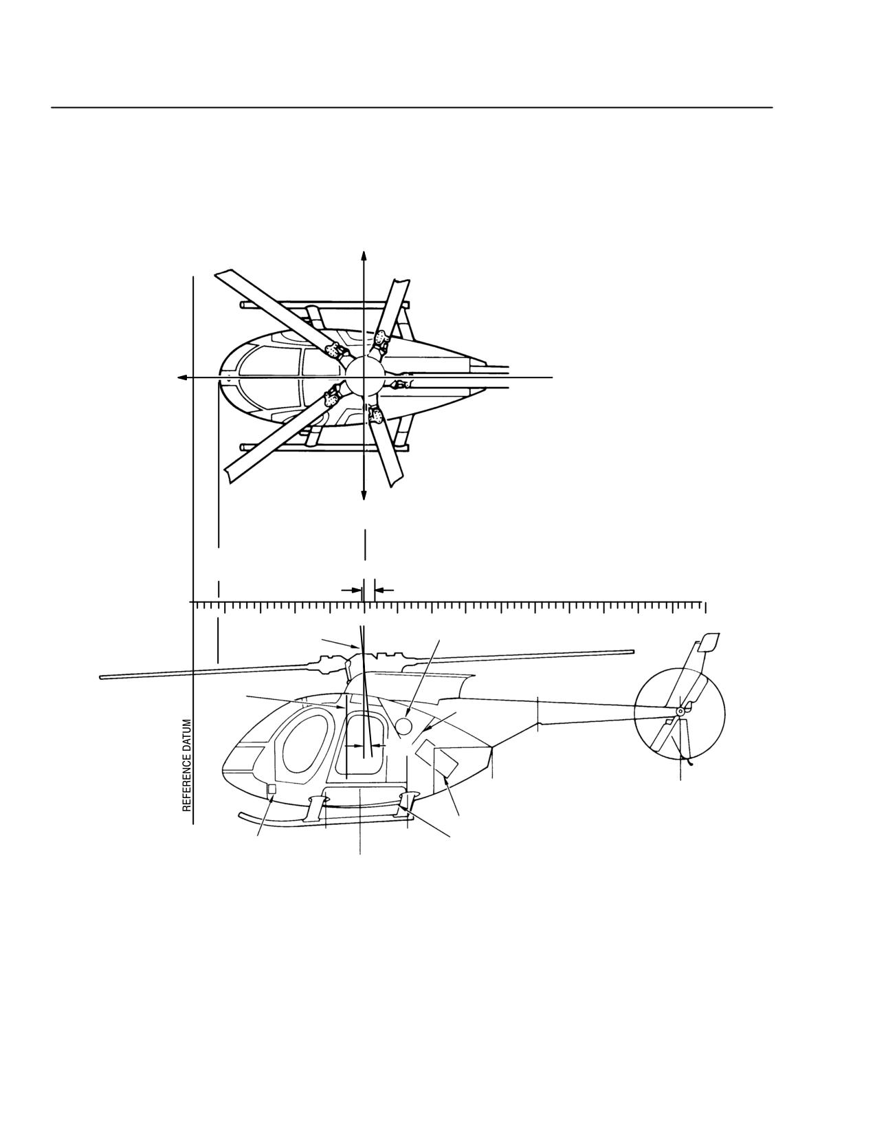
MD 500E
CSP-E-1
ROTORCRAFT FLIGHT MANUAL
(Model 369E)
Weight and Balance Data
LATERAL
``+'' CG
REFERENCE
FORWARD
CENTERLINE
STA
100.0
STA
15.00
99.0
107.4
PERMISSIBLE CG LIMITS
20
40
60
80
100
120
140
160
180
200
220
240
260
280
300
SLING POINT
OIL TANK-RH SIDE
LEVELING PLUMB
STA 92.6
FIRE WALL
JIG POINT
3°
AFT JACKING
POINT STA 197.2
STA 174.0
BHD
STA 284.0
ENGINE SECTION
BATTERY
STA
STA
FUEL CELL
78.5
124.0
COMPARTMENT
JIG POINT
FWD JACKING POINT
STA 96.9
BL "25.6
WL 11.98
F03-020-2
Figure 6-2. Reference Coordinates (Sheet 2 of 2)
6-4
Revision 14
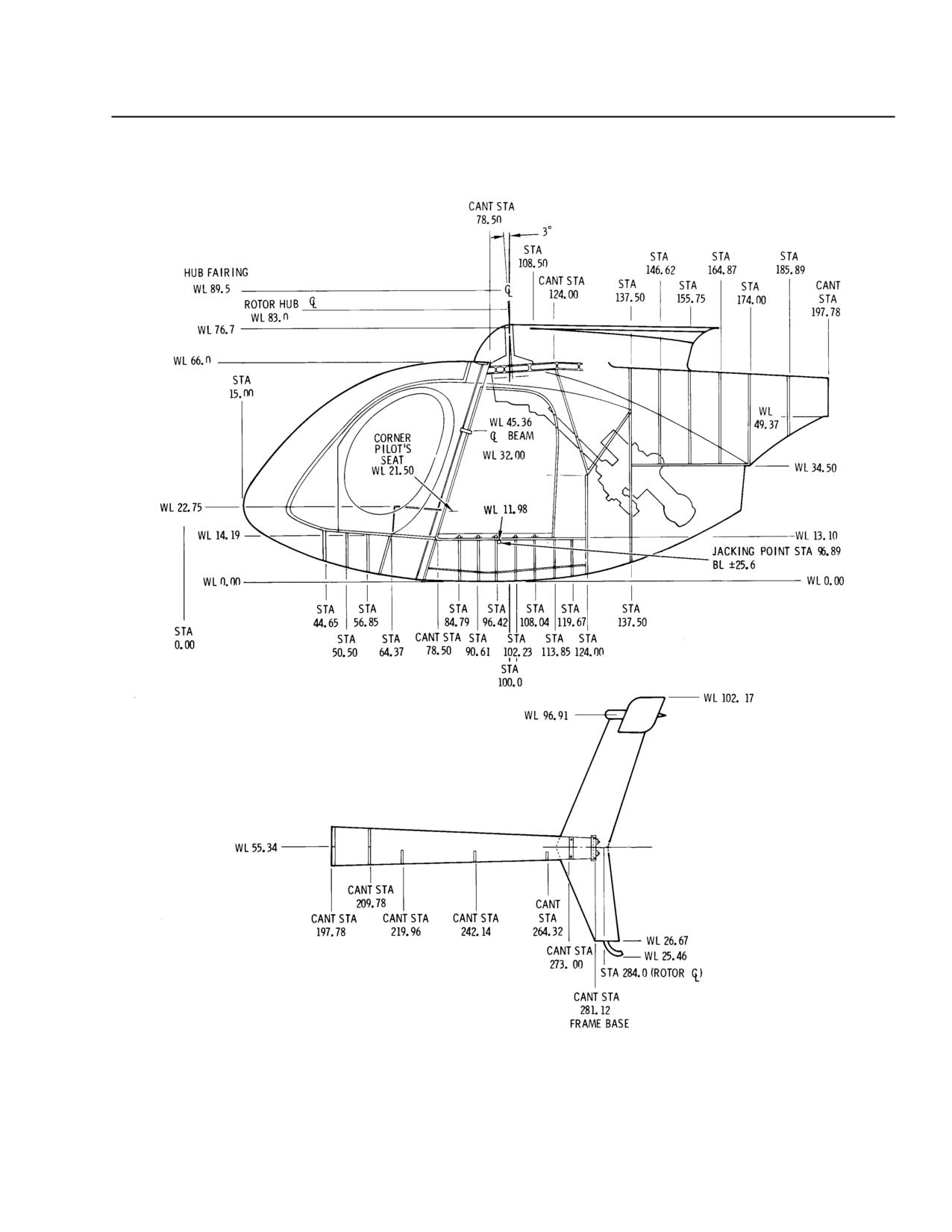
MD 500E
ROTORCRAFT FLIGHT MANUAL
CSP-E-1
(Model 369E)
Weight and Balance Data
F03-021
Figure 6-3. Station Diagram
Revision 14
6-5
MD 500E
CSP-E-1
ROTORCRAFT FLIGHT MANUAL
(Model 369E)
Weight and Balance Data
6-2. WEIGHT AND BALANCE CRITERIA
Use the delivered weight as recorded in the Weight and Balance Record in-
serted in this section to perform all weight and balance computations. Deliv-
ered weight includes oil and unusable fuel.
6-3. EQUIPMENT REMOVAL OR INSTALLATION
Removal or addition of equipment must be entered on the repair and alteration
report form, FAA 337, in accordance with Federal Air Regulations which shall
then become part of the helicopter log book file.
Record the weight and balance effects of these changes in the Weight And Bal-
ance Record inserted in this section.
Use the balance and station diagrams as an aid for weight and balance
changes.
6-6
Revision 14
MD 500E
ROTORCRAFT FLIGHT MANUAL
CSP-E-1
(Model 369E)
Weight and Balance Data
WEIGHT AND BALANCE REPORT
MODEL 500
WEIGHED BY:
J. Doe
DATE 4 October 1982
MODEL
369E SERIAL NO.
REGISTRATION NO.
TARE OR
SCALE
NET
WEIGHING
CALIBRATION
ARM
MOMENT
READING
WEIGHT
POINTS
CORRECTION
(IN.)
(IN. LB)
(LBS)
(LBS)
(LBS)
LEFT MAIN
721.7
0.0
721.7
96.9
69933
RIGHT MAIN
591.7
0.0
591.7
96.9
57915
TAIL
182.0
0.0
182.0
197.2
35890
TOTAL UNADJUSTED NET WEIGHT
1495.4
109.1
163138
TOTAL WEIGHT OF SURPLUS EQUIPMENT (SEE TABLE 1)
-1.3
96.9
-126
TOTAL WEIGHT OF MISSING EQUIPMENT (SEE TABLE 1)
15.9
97.4
+1549
TOTAL BASIC WEIGHT
1510.0
109.0
164561
REFER TO THE OWNER'S MANUAL FOR C.G. LIMITS APPLICABLE FOR GROSS WEIGHT RANGE
FUEL/OIL AT TIME OF WEIGHING
EMPTY
FULL
FUEL
X
ENGINE OIL
X
MAIN GEAR BOX
X
TAIL GEAR BOX
X
Figure 6-4. Sample Weight and Balance Report (Sheet 1 of 2)
Revision 14
6-7
MD 500E
CSP-E-1
ROTORCRAFT FLIGHT MANUAL
(Model 369E)
Weight and Balance Data
MODEL 369E SERIAL NO.
REGISTRATION NO.
DATE 7/11/91
EXAMPLES OF FORWARD, AFT, AND LATERAL LOADING
LONG.
LONG.
EXAMPLE 1, FORWARD
WEIGHT
ARM
MOMENT
(LBS.)
(IN.)
(IN.-LB.)
BASIC WEIGHT
1510.0
109.0
164561
PILOT
170.0
73.5
12495
PASSENGER - FWD. R.H.
170.0
73.5
12495
CRITICAL FUEL QUANTITY
40.0
91.6
3664
GROSS WEIGHT (CRITICAL FUEL) - FWD C.G.
1890.0
102.2
193215
APPROVED FWD C.G. LIMIT FOR EXAMPLE 1 GROSS WEIGHT 99.0 INCHES.
LONG.
LONG.
EXAMPLE 2, AFT
WEIGHT
ARM
MOMENT
(LBS.)
(IN.)
(IN.-LB.)
BASIC WEIGHT
1510.0
109.0
164561
PILOT
170.0
73.5
12495
PASSENGER - AFT L.H.
170.0
105.0
17850
PASSENGER - AFT R.H.
170.0
105.0
17850
BAGGAGE - UNDER AFT SEAT
50.0
110.0
5500
GROSS WEIGHT (ZERO FUEL) - AFT C.G.
2070.0
105.4
218256
APPROVED AFT C.G. LIMIT FOR EXAMPLE 2 GROSS WEIGHT 105.8 INCHES.
LATRL.
LATRL.
EXAMPLE 3, LATERAL
WEIGHT
ARM
MOMENT
(LBS.)
(IN.)
(IN.-LB.)
BASIC WEIGHT
1510.0
0
0
PILOT
170.0
- 13.0
- 2210
PASSENGER - AFT L.H.
170.0
- 12.2
- 2074
GROSS WEIGHT(ZERO FUEL) - LATERAL C.G.
1850
- 2.3
- 4284
APPROVED LATERAL C.G. LIMIT FOR EXAMPLE 3 GROSS WEIGHT ± 3 INCHES.
Figure 6-4. Sample Weight and Balance Report (Sheet 2 of 2)
6-8
Revision 14
MD 500E
ROTORCRAFT FLIGHT MANUAL
CSP-E-1
(Model 369E)
Weight and Balance Data
TABLE 1
SURPLUS AND MISSING EQUIPMENT
Model
369E
Serial No.
Registration No.
Date
WEIGHT
ARM - INCHES
MOMENT - IN/LBS
EQUIPMENT - ITEM
LBS
LONG
LATR
LONG
LATR
SURPLUS EQUIPMENT TOTAL:
(
1.3
)
( 96.9)
(
0
)
(
126
)
(
0
)
JACK PADS (2)
1.3
96.9
0
126
0
MISSING EQUIPMENT TOTAL:
(15.9)
( 97.4 )
( - 0.0 )
(
1549
)
(
- 0
)
ONE QT ENGINE OIL
2.1
133.1
0.0
280
0
UNUSABLE FUEL
12.0
93.0
0.0
1116
0
FLIGHT MANUAL
1.8
85.0
0.0
155
0
Page
3 of
4
Figure 6-5. Sample Surplus and Missing Items
Revision 14
6-9
MD 500E
CSP-E-1
ROTORCRAFT FLIGHT MANUAL
(Model 369E)
Weight and Balance Data
F03-022
Figure 6-6. Sample Weight and Balance Record
6-10
Revision 14
MD 500E
ROTORCRAFT FLIGHT MANUAL
CSP-E-1
(Model 369E)
Weight and Balance Data
6-4. WEIGHT AND BALANCE DETERMINATION - PASSENGER
CONFIGURATION
To determine that the gross weight and longitudinal center of gravity (fore and
aft) for a given flight are within limits, proceed as follows:
Obtain aircraft delivered weight and moment from the Weight and Balance
Record inserted in this section.
Determine weights and moments of useful load items (Ref. Figure 6-2, and
Figure 6-7).
Add above items (see Example I).
Determine corresponding center of gravity for gross weight by dividing total
moment by gross weight. This computation must be done with zero fuel
gross weight and with mission fuel gross weight (see Example I).
NOTE: If loadings are not symmetrical about the aircraft centerline, determine lateral
CG’s as described in Paragraphs 6-6 and 6-7.
Weight and balance must be computed for minimum front seat
CAUTION
weight prior to loading any passengers in rear seats with only pilot
in front. Ballast, if required, must be carried.
NOTE: Ballast may be carried in the utility stowage compartment or stowed and secured
by seat belt and shoulder harness in opposite front seat. Ballast may consist of
shot, sandbags, or similar material, adequately contained and secured.
Revision 14
6-11
MD 500E
CSP-E-1
ROTORCRAFT FLIGHT MANUAL
(Model 369E)
Weight and Balance Data
EXAMPLE I. Longitudinal CG Calculation - Passenger
Items
Weight
Moment
(lb)
(in.-lb)
Delivered Weight
1,510
164,561
Pilot
170
12,495
Passenger - Fwd Outboard
170
12,495
Passenger - Aft R/H
170
17,850
Passenger - Aft L/H
170
17,850
Utility Stowage (Station 52.9)
20
1058
Baggage (under seat, Station 110.0)
40
4,400
1. Zero Fuel Weight
2,250
230,709
Add Useable Fuel (62.1 GAL Jet a @ 6.8
422
41,229
LB/GAL)
2. Gross Weight
2,672
271,938
Calculation of Longitudinal CG
CG (Zero Fuel Weight):
Moment at Zero Fuel Weight
= 230,709
= 102.5 IN.
Zero Fuel Weight
2,250
CG (Gross Weight):
Moment at Gross Weight =
271,938
= 101.8 IN.
Gross Weight
2,672
NOTE: The CG falls within the limits specified in Table 6-1.
6-12
Revision 14
MD 500E
ROTORCRAFT FLIGHT MANUAL
CSP-E-1
(Model 369E)
Weight and Balance Data
6-5. LONGITUDINAL LOADING OF CARGO
The large aft compartment of the Model 369E provides great flexibility in the
variety of cargo loads it can accommodate.
In general, the placement of cargo CG within 4 inches of the center of the
compartment will ensure that the helicopter will be within the approved CG
limits.
To determine the gross weight and center of gravity for a given flight are with-
in limits, proceed as follows.
Establish the weight of the cargo load.
Determine the location of the cargo longitudinal CG by measuring the dis-
tance to the cargo from the jacking point located on the side of the fuselage
(station 96.9).
Cargo CG = 96.9 ± measured distance (inches); ie., + if aft of mark, - if for-
ward of mark.
Obtain the cargo moment:
Cargo Moment = Cargo Weight x Cargo CG
Perform weight and balance as previously described for passenger configura-
tion.
Revision 14
6-13
MD 500E
CSP-E-1
ROTORCRAFT FLIGHT MANUAL
(Model 369E)
Weight and Balance Data
EXAMPLE II. Longitudinal CG Calculation - Passenger and Cargo
Weight
Moment
Items
(lb)
(in.-lb)
Delivered Weight
1,510
164,561
Pilot
170
12,495
Passenger - Fwd Outboard
170
12,495
Cargo (Station 100.0)
1000
100,000
1. Zero Fuel Weight
2,850
289,551
Add Usable Fuel (22.0 GAL Jet a @ 6.8
150
14,175
LB/GAL)
2. Gross Weight
3,000
303,726
Calculation of Longitudinal CG
CG (Zero Fuel Weight):
Moment at Zero Fuel Weight
= 289,551
= 101.6 IN.
Zero Fuel Weight
2,850
CG (Gross Weight):
Moment at Gross Weight =
303,756
= 101.2 IN.
Gross Weight
3,000
NOTE: The CG falls within the limits specified in Table 6-1.
6-14
Revision 14
MD 500E
ROTORCRAFT FLIGHT MANUAL
CSP-E-1
(Model 369E)
Weight and Balance Data
6-6. PERMISSIBLE LATERAL LOADINGS
Safe operation of this helicopter requires that it be flown within established
lateral as well as longitudinal center of gravity limits.
It is therefore imperative that lateral center of gravity control be exercised.
All combinations of internal and external loadings are permissible if gross
weight, longitudinal, and lateral center of gravity considerations permit.
For crew and passenger lateral center of gravity, see Figure 6-2.
6-7. LATERAL LOADING OF CARGO
To determine if the gross weight and lateral center of gravity for a given flight
are within limits. Proceed as follows:
Find weight of load.
Determine lateral location (station) of load center of gravity.
Measure load distance from aircraft centerline (lateral station zero), right
(+); left (-).
Obtain the lateral load moment as follows:
Lateral moment = weight X lateral station. (See Example III.)
Revision 14
6-15
MD 500E
CSP-E-1
ROTORCRAFT FLIGHT MANUAL
(Model 369E)
Weight and Balance Data
EXAMPLE III. Lateral CG Calculation - Passenger and Cargo
Weight
Lateral
Lateral Moment
Items
(lb)
Arm (in)
(in.-lb)
Delivered Weight
1,510
0
0
Pilot (L/H)
170
-13.0
-2,210
Passenger - Fwd (R/H)
170
+15.5
+2,635
Cargo
1000
+2.0
+2,000
1. Zero Fuel Weight
2,850
+0.9
+2,425
Add Usable Fuel (22.0
150
0
0
GAL Jet a @ 6.8 LB/GAL)
2. Gross Weight
3,000
+0.8
+2,425
Calculation of Lateral CG
CG (Zero Fuel Weight):
Moment at Zero Fuel Weight
= +2,425
= +0.9 IN.
Zero Fuel Weight
2,850
CG (Zero Fuel Weight):
Moment at Gross Weight = +2,425
= +0.8 IN.
Gross Weight
3,000
NOTE: The CG falls within the limits specified in Table 6-1.
6-16
Revision 14
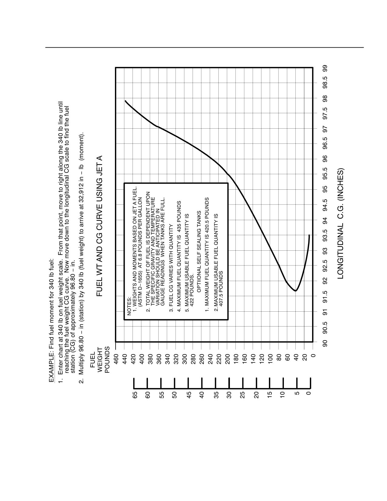
MD 500E
ROTORCRAFT FLIGHT MANUAL
CSP-E-1
(Model 369E)
Weight and Balance Data
F03-023-1
Figure 6-7. Fuel Station Diagram (Jet-A at 6.8 Pounds per Gallon) (Sheet 1 of 2)
Revision 14
6-17
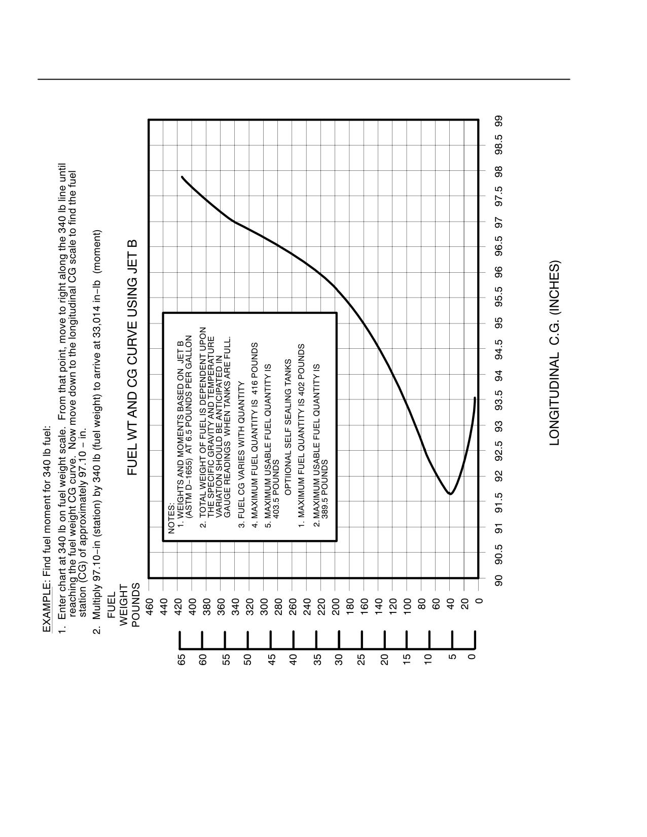
MD 500E
CSP-E-1
ROTORCRAFT FLIGHT MANUAL
(Model 369E)
Weight and Balance Data
F03-023-2
Figure 6-7. Fuel Station Diagram (Jet-B at 6.5 Pounds per Gallon) (Sheet 2 of 2)
6-18
Revision 14
MD 500E
ROTORCRAFT FLIGHT MANUAL
CSP-E-1
(Model 369E)
Weight and Balance Data
Table 6-2. Weights and Longitudinal Moments - Pilot, Passenger, Baggage
Pilot and Passenger Weights and Longitudinal Moments
Moment
Moment
Moment
Passenger
(in.-lb)
(in.-lb)
(in.-lb)
Weight (lb)
Pilot or Fwd
Center Fwd
Aft Passenger
R/H Passenger
Passenger
R/H and L/H
Station 73.5
Station 71.5
Station 105.0
120
8,820
8,580
12,600
140
10,290
10,010
14,700
160
11,760
11,440
16,800
170
12,495
12,155
17,850
180
13,230
12,870
18,900
200
14,700
14,300
21,000
220
16,170
15,730
23,100
240
17,640
17,160
25,200
Baggage Weights and Longitudinal Moments
Moment
Moment
Moment
Moment
Baggage
(in.-lb)
(in.-lb)
(in.-lb)
(in.-lb)
Weight
Utility Stowage
Under Seat
(lb)
Compartment
Fwd Bulkhead
and Center
Behind Seat
Station 52.9
Station 87
Station 110
Station 120
10
529
870
1,100
1,200
20
1,058
1,740
2,200
2,400
30
1,587
2,610
3,300
3,600
40
2,116
3,480
4,400
4,800
*50
2,645
4,350
5.500
6,000
60
-
5,220
6,600
7,200
70
-
6,090
7,700
8,400
80
-
6,960
8,800
9,600
90
-
7,830
9,900
10,800
100
-
8,700
11,000
12,000
*Maximum Capacity
Revision 14
6-19
MD 500E
CSP-E-1
ROTORCRAFT FLIGHT MANUAL
(Model 369E)
Weight and Balance Data
Table 6-3. Weights and Lateral Moments - Pilot, Passenger, Baggage
Moment
Moment
Moment
Moment
Passenger
(in.-lb)
(in.-lb)
(in.-lb)
(in.-lb)
Weight
Pilot
Passenger
Passenger
Aft Passenger
(lb)
L/H
R/H Fwd
Center Fwd
R/H and L/H
Station-13.0
Station+15.5
Station +0.8
Station ±12.2
120
-1,560
+1,860
+ 96
±1,464
140
-1,820
+2.170
+112
±1,708
160
-2,080
+2,480
+128
±1,952
170
-2,210
+2,635
+136
±2,074
180
-2,340
+2,790
+144
±2,196
200
-2,600
+3,100
+160
±2,440
220
-2,860
+3,410
+176
±2,684
240
-3,120
+3,720
+192
±2,928
BAGGAGE WEIGHTS AND MOMENTS
Baggage Weight (lb)
Moment
Station +12.8
(in.-lb)
10
+128
20
+256
30
+348
40
+512
50
+640
6-20
Revision 14
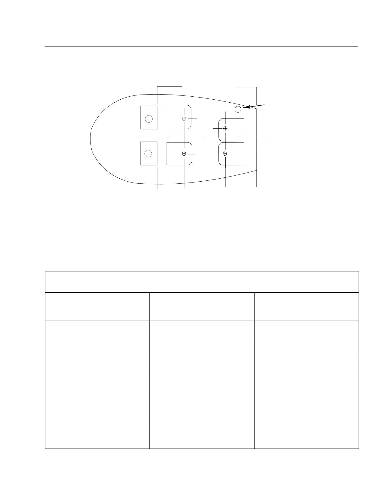
MD 500E
ROTORCRAFT FLIGHT MANUAL
CSP-E-1
(Model 369E)
Weight and Balance Data
CG OF PASSENGERS
FUEL FILLER
INLET LINE
RH
+12.0 IN.
(+)
+5.2 IN.
FWD C
L
KIT WEIGHT = 17.9 LB
LH
KIT CG = 101.4 IN. LONGITUDINAL
-12.0 IN.
(-)
-1.0 IN. LATERAL
STA
STA
STA
STA
78.5
95.5
109.2
124.0
F03-024
Aft Compartment Passenger Weights and Longitudinal Moments
(High Density Seating)
Table 6-4. Weight and Loading for 369H90035-503 Seating and Belts
for Four Installation (High Density Seating)
Passenger (s)
Moment (In. lb),
Moment (in.-lb),
(lb)
Fwd position
Aft Position
(Sta 95.5)
(Sta 109.2)
150
14,300
16,400
175
16,700
19,100
200
19,100
21,800
225
21,500
24,600
250
23,900
27,300
275
26,300
30,000
300
28,700
32,800
325
31,000
35,500
350
33,400
38,200
375
35,800
41,000
400
38,200
43,700
Revision 14
6-21
MD 500E
CSP-E-1
ROTORCRAFT FLIGHT MANUAL
(Model 369E)
Weight and Balance Data
6-8. INTERNAL LOADING OF CARGO
The following instructions should be followed when carrying internal cargo.
Rope, cable, or equivalent must have a minimum loop strength of 1,800
pounds.
Restrain the cargo from shifting by using the correct number of restraining
loops in accordance with Table 6-5.
Position restraining loop in accordance with Figure 6-8.
Cargo deck capacity is 1300 pounds (not to exceed 115 pounds per square
foot).
View II shows typical tiedown for 500-pound cargo.
Restraint loops are to be secured as indicated and tied to the cargo to pre-
vent slippage of the loops.
Variations of the tiedown are allowable, providing total restraint require-
ments are met.
Caution should be exercised to keep the cargo from bearing against the cen-
ter slanted portion of the aft bulkhead.
Table 6-5. Cargo Weight Versus Loop Restraint
Number of Required Restraint Loops
Cargo
Forward
Aft
Vertical/Lateral
(lb)
Restraint
Restraint
Restraint
Up to 100
1
1
2
101 to 300
2
1
2
301 to 400
3
2
2
401 to 600
4
2
2
601 to 800
5
3
2
801 to 1000
6
3
3
1001 to 1100
7
4
3
1101 to 1200
8
4
3
1201 to 1300
8
4
3
*Note the 7th and 8th loops are to use the outboard seat belt attach
fitting (Station 124).
6-22
Revision 14
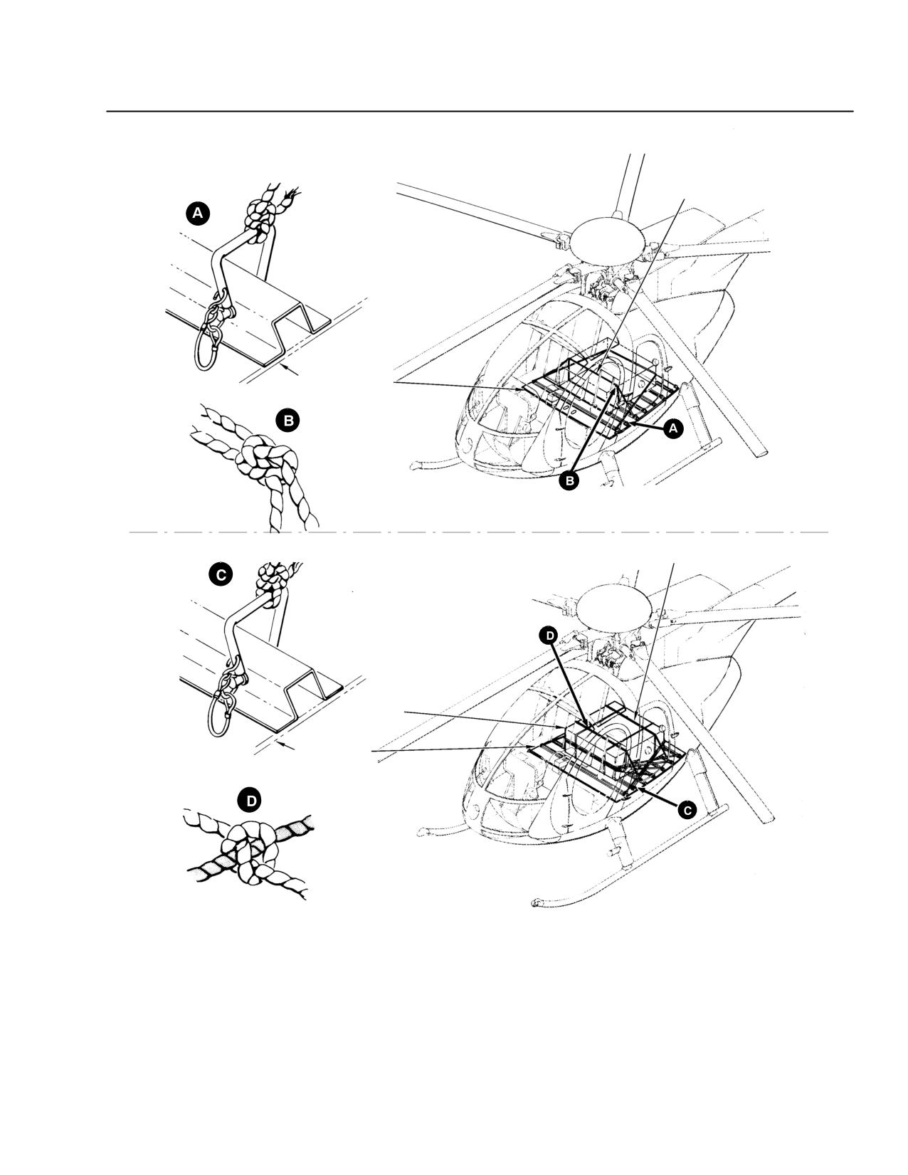
MD 500E
ROTORCRAFT FLIGHT MANUAL
CSP-E-1
(Model 369E)
Weight and Balance Data
VIEW I
LOOP FOR VERTICAL AND
LATERAL RESTRAINT
A
CARGO FLOOR
VIEW SHOWING LOCATION OF CARGO TIEDOWN POINTS
AND LOOPS - MINIMUM LOOP STRINGTH - 1800 LB
WRAP CONTAINER WITH SIMILAR STRAP SUCH
VIEW II
THAT LOOPS CANNOT SLIP
CARGO
CARGO FLOOR
VIEW SHOWING 500 LB CARGO RESTRAINED
F03-025
Figure 6-8. Cargo Restraint
Revision 17
6-23
MD 500E
CSP-E-1
ROTORCRAFT FLIGHT MANUAL
(Model 369E)
Weight and Balance Data
This page intentionally left blank!
6-24
Revision 17
MD 500E
ROTORCRAFT FLIGHT MANUAL
CSP-E-1
(Model 369E)
Handling Servicing
and Maintenance
S ECTION VII
HANDLING, SERVICING
AND MAINTENANCE
TABLE OF CONTENTS
PARAGRAPH
PAGE
7-1.
Helicopter Components
7-1
7-2.
Use of External Power
7-1
7-3.
Hoisting, Jacking, and Lifting
7-1
Figure 7-1. MD 369E Helicopter - Major Components
7-2
7-4.
Ground Handling Wheels
7-3
Figure 7-2. Ground Handling Wheels
7-3
7-5.
Moving and Towing Helicopter
7-4
7-6.
Parking and Mooring
7-5
Figure 7-3. Parking and Mooring
7-6
7-7.
Servicing - General
7-7
Table 7-1. Servicing Materials (Operating Supplies)
7-7
Figure 7-4. Servicing Points (Sheet 1 of 2)
7-12
Figure 7-4. Servicing Points (Sheet 2 of 2)
7-13
7-8.
Fuel System - Servicing
7-14
7-9.
Engine Oil System - Servicing
7-15
7-10. Main Rotor and Tail Rotor Transmission - Servicing
7-15
7-11. Cleaning General
7-16
7-12. Cleaning Fuselage Interior Trim and Upholstery
7-16
7-13. Cleaning Aircraft Exterior and Rotor Blades
7-17
7-14. Cleaning - Canopy and Door Transparent Plastic
7-17
7-15. Fluid Leak Analysis
7-17
7-16. Preservation and Storage
7-18
7-17. Flyable Storage - No Time Limit
7-18
7-18. Cockpit Door Removal and Installation
7-19
Figure 7-5. Pilot and Passenger/Cargo Door Removal
7-20
7-19. Special Operational Checks and Procedures
7-21
Compressor Wash
7-21
Main Rotor Hub Balancing
7-22
Revision 18
7-i
ROTORCRAFT FLIGHT MANUAL
MD 500E
CSP-E-1
(Model 369E)
Handling Servicing
and Maintenance
This page intentionally left blank!
7-ii
Revision 17
MD 500E
ROTORCRAFT FLIGHT MANUAL
CSP-E-1
(Model 369E)
Handling, Servicing,
and Maintenance
SECTION VII
HANDLING SERVICING
AND MAINTENANCE
7-1. HELICOPTER COMPONENTS
The major components of the helicopter are shown in Figure 7-1.
7-2. USE OF EXTERNAL POWER
An external receptacle is located at the right side of the pilot's compartment
seat structure. The right door must be open to use the receptacle. Any source
of external 28-volt, direct-current power with sufficient amperage rating may
be used. Engine starting requirements are approximately 375 amperes, mini-
mum.
Before connecting external power, be sure that helicopter main electrical power
selector switch is OFF.
After power is connected to receptacle, power switch must be set to EXT posi-
tion to connect external power to helicopter electrical system.
7-3. HOISTING, JACKING, AND LIFTING
Hoisting, lifting, and jacking of the helicopter shall only be
CAUTIONperformed by qualified maintenance personnel with the proper
equipment and tools as specified in the Handbook of Maintenance
Instructions. Failure to follow the specified procedures may result
in damage to aircraft components.
Revision 14
7-1
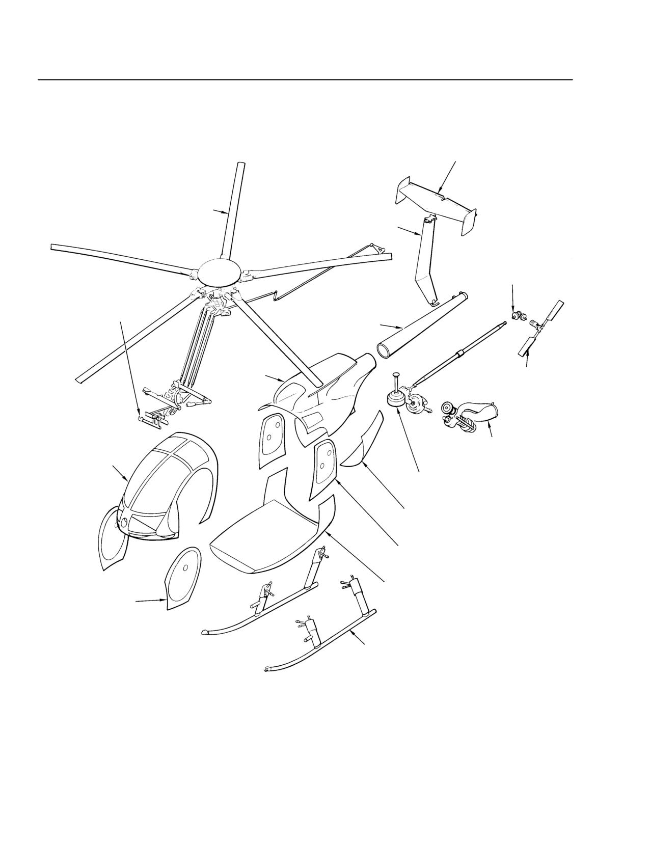
CSP-E-1
ROTORCRAFT FLIGHT MANUAL
MD 500E
(Model 369E)
Handling, Servicing,
and Maintenance
HORIZONTAL STABILIZER
MAIN ROTOR INSTALLATION
VERTICAL STABILIZER
TAIL ROTOR
TRANSMISSION
FLIGHT CONTROLS
INSTALLATION
TAILBOOM
AFT SECTION
INSTALLATION
TAIL ROTOR
ASSEMBLY
ENGINE
FORWARD SECTION
INSTALLATION
INSTALLATION
MAIN TRANSMISSION
AND POWER TRAIN
ENGINE ACCESS
DOOR
CARGO DOOR
PILOT DOOR
LOWER SECTION INSTALLATION
ASSEMBLY
LANDING GEAR
F30-026
Figure 7-1. MD 369E Helicopter - Major Components
7-2
Revision 14
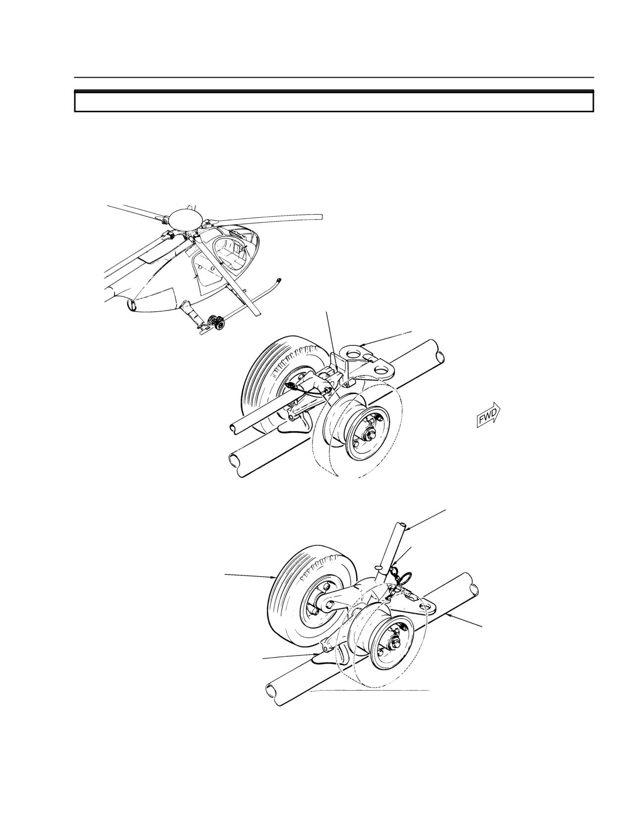
MD 500E
ROTORCRAFT FLIGHT MANUAL
CSP-E-1
(Model 369E)
Handling, Servicing,
and Maintenance
7-4. GROUND HANDLING WHEELS
Standard ground handling wheels, available as a special tool for helicopters not
equipped with floats, are used for moving helicopter by hand and for towing
helicopter (Ref. Figure 7-2).
At regular intervals, check that wheel tire pressure is a maximum of 80 to 90
psi.
WARNING:
BE SURE LOCK SNAPS INTO
POSITION SHOWN BEFORE
RELEASING JACK HANDLE
LOCK
TOW BAR FITTING
WHEELS LOWERED AND LOCKED
(HELICOPTER RAISED)
JACK HANDLE
HANDLE LOCK PIN
GROUND HANDLING WHEELS
AND JACK ASSEMBLY
SKID TUBE
(RIGHT SIDE SHOWN)
SKID FITTING
WHEELS RAISED
F03-029
(HELICOPTER LOWERED)
Figure 7-2. Ground Handling Wheels
Revision 14
7-3
CSP-E-1
ROTORCRAFT FLIGHT MANUAL
MD 500E
(Model 369E)
Handling, Servicing,
and Maintenance
7-5. MOVING AND TOWING HELICOPTER
Manual moving:
Excessive lead-lag load applied to the main rotor blades during
CAUTIONground handling can result in damage to the elastomeric damper
buns and failure of the damper assembly. Operators should use
extra caution to avoid lead-lag loads in excess of 35 pounds at
the tip of the main rotor blades.
Ensure all stress panels are installed on helicopter before moving.
Attach ground handling wheels (Ref. Figure 7-2) and hold tail up while low-
ering the wheels (raising helicopter).
Manually move helicopter on ground handling wheels by balancing at tail-
boom and pushing on rear fuselage portion of air frame.
Towing:
Tow helicopter on ground handling wheels by attaching suitable tow bar to
tow bar fittings. If tow bar is not equipped to keep front ends of skid tubes
from dragging, have an assistant balance helicopter at tailboom.
Ensure all stress panels are installed on helicopter before moving.
Except under extreme emergency conditions, do not tow helicopter
CAUTION
at speeds over 5 mph. Do not allow front end of skid tubes to drag
on ground. Avoid sudden stops and starts and short turns which
could cause helicopter to turn over. Allow inside wheel to turn (not
pivot) while helicopter is being turned. Safe minimum turning ra-
dius is approximately 20 feet.
7-4
Revision 14
MD 500E
ROTORCRAFT FLIGHT MANUAL
CSP-E-1
(Model 369E)
Handling, Servicing,
and Maintenance
7-6. PARKING AND MOORING
Parking (Ref. Figure 7-3):
To prevent rotor damage from blade flapping (droop stop pound-
CAUTION
ing) as a result of air turbulence from other aircraft landing, taking
off or taxiing or sudden wind gusts, rotor blades should be secured
whenever helicopter is parked.
Locate helicopter slightly more than blade clearance from nearby objects on
most level ground available.
Apply friction to lock cyclic and collective sticks so that friction control
knobs are positioned as follows: neutral for cyclic stick an full down for col-
lective stick.
Secure main rotor blades as follows.
Turn blades until one blade is directly above tailboom (Ref. Figure 7-3).
Install blade socks on all blades.
Secure blade sock tiedown cord for blade located above tailboom to tailboom.
Secure other blade sock tiedown cords to fuselage jack fittings or cabin
steps.
When securing blade sock tiedown cords, take up slack, but do not
CAUTION
apply excessive bending loads on blades.
Mooring (Ref. Figure 7-3):
Whenever severe storm conditions or wind velocities higher than 40 knots
are forecast, helicopter should be hangared or evacuated to safer area.
Park helicopter and remove main rotor blades.
Install pitot tube cover.
Fill fuel tank (if possible).
Apply friction to lock cyclic and collective sticks.
Secure helicopter to ground by attaching restraining lines (cable or rope) be-
tween jack fittings and stakes or ground anchors.
Install air inlet fairing cover on air inlet front fairing.
Install engine exhaust cover on exhaust tailpipe.
Revision 14
7-5
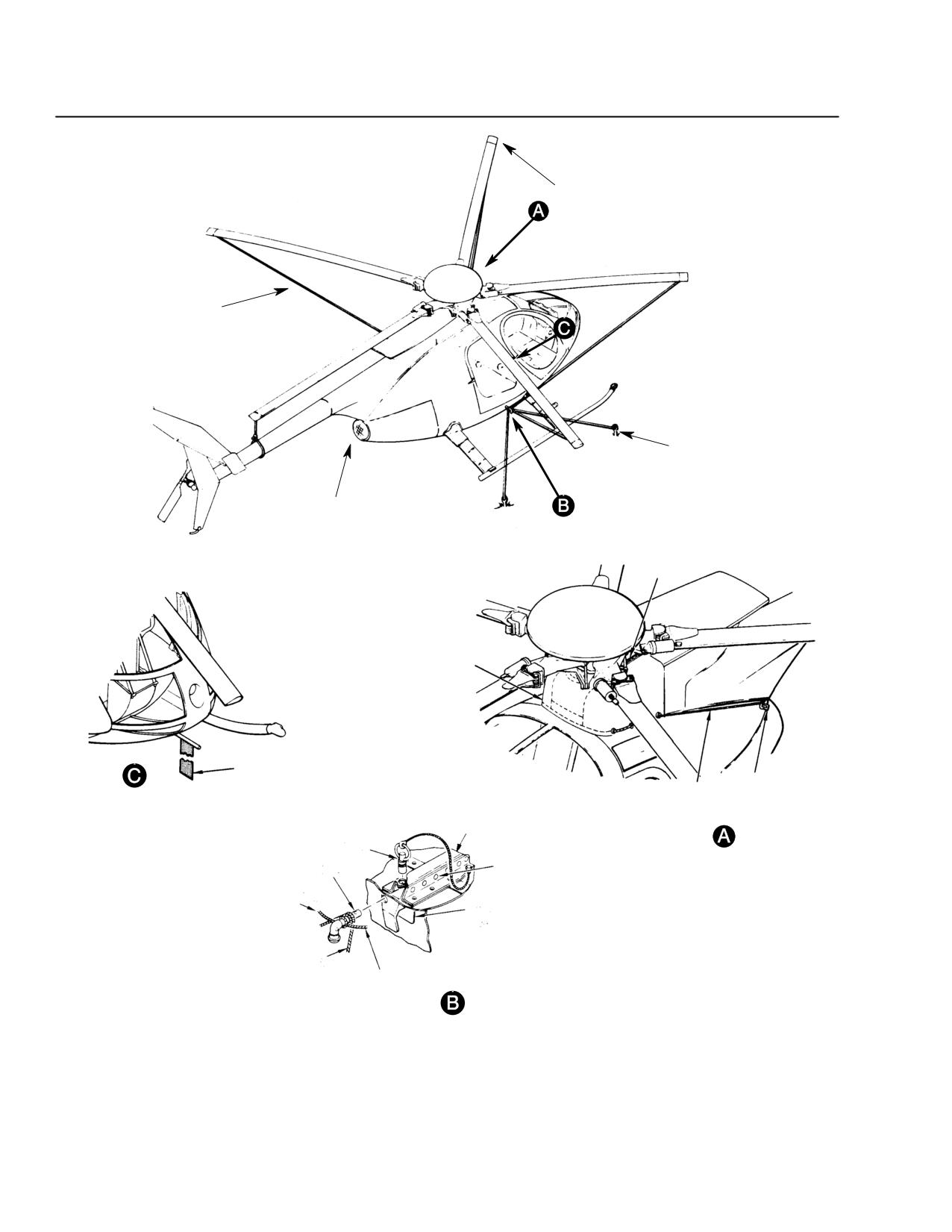
CSP-E-1
ROTORCRAFT FLIGHT MANUAL
MD 500E
(Model 369E)
Handling, Servicing,
and Maintenance
BLADE SOCK
(5 PLACES)
TIEDOWN TETHER
MOORING ANCHOR
(4 PLACES)
ENGINE EXHAUST
COVER
ZIPPER
AIR INLET
FAIRING
COVER
PITOT TUBE
COVER
DOOR
TIE CORD
ACCESS
PITOT TUBE
LATCH
FUEL CELL
COVER INSTALLATION
ACCESS DOOR
LOCKPIN
LOCKPIN
ENGINE AIR INLET
JACK FITTING
STOWAGE
FAIRING COVER
INSTALLATION
FUESELAGE
STRUCTURE
JACK FITTING
TO MOORING
ANCHOR
TO BLADE
SOCK
JACK FITTING INSTALLATION
(TYPICAL - 2 PLACES)
F03-030
Figure 7-3. Parking and Mooring.
7-6
Revision 14
MD 500E
ROTORCRAFT FLIGHT MANUAL
CSP-E-1
(Model 369E)
Handling, Servicing,
and Maintenance
7-7. SERVICING - GENERAL
Servicing helicopter includes replenishment of fuel, changing or replenishment
of oil and other such maintenance functions.
Fuels, oils, other servicing materials and capacities are listed in Table 7-1.
NOTE: Check the appropriate Rolls-Royce Operation and Maintenance Manual for
complete listing of approved lubricants.
Locations of servicing points are shown in Figure 7-4.
Table 7-1. Servicing Materials (Operating Supplies)
1. Tail Rotor Transmission - Capacity 0.5 US Pt (0.23 Liter)
Use the materials listed under Item 4 or decal on on transmission (Refer to SB369E-104).
2. Main Transmission (369D25100) - Capacity: 12.0 US Pt (5.67 liters)
Use the materials listed under Item 4 or Mobil AGL (See Footnote 4).
3. Main Transmission (369F5100) - Capacity: 14.0 US Pt (6.62 liters).
Use Mobil AGL only (See Footnote 4).
4. Engine - Capacity: 3.0 US Qt. (2.84 liters)
Ambient Temperature
Oil Type
0°C (32°F) and above
MIL-PRF-23699C or subsequent preferred
0°C (32°F) to -40°C (-40°F) MIL-PRF-23699C or subsequent preferred or
MIL-PRF-7808G or subsequent
-40°C (-40°F) and below
MIL-PRF-7808G or subsequent only
Specification
Material
Manufacturer
MIL-PRF-7808 (see Footnote 2 and 3)
American PQ Lubricant 6899
American Oil and Supply Co.
238 Wilson Ave.
Newark, NJ 07105
BP Turbo Oil 2389
BP Corporation North America Inc.
Exxon Turbo Oil 2389
1500 Valley Rd
Wayne, NJ 07470-2040
Brayco 880
Air BP Lubricants
Maple Plaza II - 1N
6 Campus Drive
Parsippany, NJ 07054
Mobil Avrex S Turbo 256
ExxonMobil Oil Corp.
Exxon
3225 Gallows Rd.
Fairfax, VA 22037-0001
Revision 18
7-7
CSP-E-1
ROTORCRAFT FLIGHT MANUAL
MD 500E
(Model 369E)
Handling, Servicing,
and Maintenance
Specification
Material
Manufacturer
MIL-PRF-7808 (Cont.) Mobil RM-201A
ExxonMobil Oil Corp.
Exxon
3225 Gallows Rd.
Fairfax, VA 22037-0001
Mobil RM-184A
ExxonMobil Oil Corp.
Exxon
3225 Gallows Rd.
Fairfax, VA 22037-0001
Stauffer Jet 1
Stauffer Chemical Co.
380 Madison Ave.
New York, NY 10017
MIL-PRF-23699 STD
AeroShell Turbine Oil 500
Shell Aviation, Ltd
Site Office
London, SE1 7NA, GBR
Royco Turbine Oil 500
Chemtura Corporation
Anderol Division
215 Merry Ln.
East Hannover, NJ 07936-3900
American PQ Lubricant 6700
American Oil and Supply Co.
238 Wilson Ave.
Newark, NJ 07105
BP Turbo Oil 2380
BP Corporation North America Inc.
Exxon Turbo Oil 2380
1500 Valley Rd
Wayne, NJ 07470-2040
Caltex RPM Jet Engine Oil 5
Caltex Petroleum Corp
380 Madison Ave.
New York, NY 10017
Castrol 5050
Castrol Industrial North America
Inc.
775 Louis Dr.
Warminster, PA 18974-2827
Chevron Jet Engine Oil 5
Chevron International Oil Co.
555 Market Street
San Francisco, CA 94105
7-8
Revision 18
MD 500E
ROTORCRAFT FLIGHT MANUAL
CSP-E-1
(Model 369E)
Handling, Servicing,
and Maintenance
Specification
Material
Manufacturer
MIL-PRF-23699 STD
Hatcol 3211
Chemtura Corporation
(Cont)
Hatco Division
1020 King Georges Post Rd.
Fords, NJ 08863-2329
Mobil Jet Oil II
ExxonMobil Oil Corp.
Exxon
3225 Gallows Rd.
Fairfax, VA 22037-0001
Stauffer Jet II
Stauffer Chemical Co.
380 Madison Ave.
New York, NY 10017
Turbonycoil 600 (TN 600)
SOC NYCO
66, Avenue des Champs Elysees
Paris, 75008, FRA
MIL-PRF-23699 HTS
AeroShell Turbine Oil 560
Shell U.K. Oil Products Ltd.
SSSC Glasgow
Gate 5, Oil Sites Rd.
Ellesmere Port,
Cheshire, CH65 4FS, GBR
Royco Turbine Oil 560
Chemtura Corporation
Anderol Division
215 Merry Ln.
East Hannover, NJ 07936-3900
BP Turbo Oil 2197
BP Corporation North America Inc.
1500 Valley Rd
Wayne, NJ 07470-2040
Mobil Jet 254
ExxonMobil Oil Corp.
Exxon
3225 Gallows Rd.
Fairfax, VA 22037-0001
Mobil Jet 291
ExxonMobil Oil Corp.
Exxon
3225 Gallows Rd.
Fairfax, VA 22037-0001
Revision 18
7-9
CSP-E-1
ROTORCRAFT FLIGHT MANUAL
MD 500E
(Model 369E)
Handling, Servicing,
and Maintenance
Specification
Material
Manufacturer
SAE AS5780 SPC
BP Turbo Oil 2380
BP Corporation North America Inc.
Exxon Turbo Oil 2380
1500 Valley Rd
Wayne, NJ 07470-2040
Mobil Jet Oil II
ExxonMobil Oil Corp.
Exxon
3225 Gallows Rd.
Fairfax, VA 22037-0001
SAE AS5780 HPC
BP Turbo Oil 2197
BP Corporation North America Inc.
1500 Valley Rd
Wayne, NJ 07470-2040
Mobil Jet 254
ExxonMobil Oil Corp.
Exxon
3225 Gallows Rd.
Fairfax, VA 22037-0001
5. Fuel Cells - Standard Nonself-sealing, Capacity: 64.0 US Gal (242 liters), 416 pounds
Optional Self-sealing, Capacity: 62.0 US Gal (234 liters), 402 pounds.
Refer to Rolls-Royce 250 Series Operations Manual for complete fuel speci-
fications.
MIL-DTL-5624 JP-4
MIL-DTL-5624 JP-5
ASTM D 1655 Jet A
ASTM D 1655 Jet A-1
ASTM D 1655 Jet B
JP-1 conforming to ASTM D
Peoples Republic of China
ASTM D 6615 Jet B
1655, Jet A or Jet A-1
RP-3.
Arctic Diesel Fuel DF-A
Diesel No. 1 conforming to
MIL-DTL-83133, grade JP-8
(W-F-800B) conforming to
ASTM D 1655, Jet A or Jet
ASTM D 1655, Jet A or Jet
A-1
A-1
CAUTION: At 4.4°C (40°F) and below, fuel must contain anti icing additive that meets
MIL-I-27686 requirements. For blending information and authorized fuels,
refer to the appropriate Rolls-Royce Operation and Maintenance Manual.
6. Overrunning Clutch (369A5350) - Capacity: 1.64 US Oz (45cc) Use the materials listed
under item 4 but not Mobil AGL (See Footnote 4).
7. Overrunning Clutch (369F5450) - Capacity: 3.64 US Oz. Use Mobil AGL
(See Footnote 4).7
7-10
Revision 18
MD 500E
ROTORCRAFT FLIGHT MANUAL
CSP-E-1
(Model 369E)
Handling, Servicing,
and Maintenance
8. One-Way Lock - Capacity: 0.67 US Oz (20cc)
MIL-PRF-5606
Brayco Micronic 756 and 756PH
Specialty Products Division
1001 West 31st Street
Downers Grove
Illinois 60515
Aero Shell Fluid 41
Shell Oil Co.
Royco 756
Anderol Inc
Mobil Aero HF
ExxonMobil Lubricants
Invarol FJ 13
ESSO Saf
2, rue des Martinets
92569 Rueil-Malmaison
Cedex, France
MIL-PRF-6083
Brayco Micronic 783
Castrol Industrial North America
Inc.
Royco 783
Anderol Inc.
Hydraunycoil FH-6
NYCO, S.A.
9. Battery (NiCad) - Capacity: As required
MS36300
Distilled Water
Any acceptable source
Footnotes:
(1)
Oils approved for use in main transmission and tail rotor transmission are synthetic
lubrication oils that have a certified Ryder Gear Value in excess of 2500 pounds per
inch.
(2)
Not a preferred lubricant for transmissions. Use MIL-PRF-7808 lubricating oil in
transmission only when other oils are not available.
(3)
For Model 250 Series engine oil change requirements and restrictions on mixing of oils,
refer to the Rolls-Royce Operation and Maintenance Manual.
DO NOT use Mobil AGL oil in 250 Series engines.
(4)
Do not use Mobil SHC 626 lubrication oil designated as
“NOT FOR AVIATION USE" on the label. Refer to SB369E-104.
WARNING: Only discretionary mixing of oils within an oil series is permitted without a time
penalty. Use of mixed oils from different series in an engine is limited to five hours
total running time during one overhaul period. Adequate maintenance records
must be maintained to ensure that the five hour limit is not exceeded. Failure to
comply with oil mixing restrictions can result in engine failure.
Revision 18
7-11
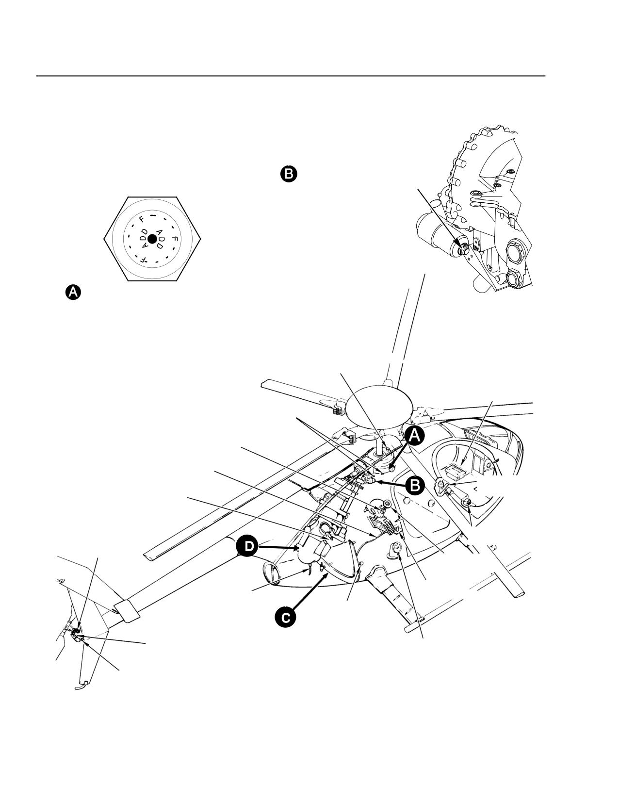
CSP-E-1
ROTORCRAFT FLIGHT MANUAL
MD 500E
(Model 369E)
Handling, Servicing,
and Maintenance
OIL FILTER BYPASS INDICATOR
(369F5100 M/R TRANSMISSION ONLY)
TRANSMISSION OIL LEVEL SIGHT GAUGE
MAIN TRANSMISSION
FILLER
BATTERY
MAIN TRANSMISSION
DRAIN VALVES
LIQUID LEVEL
SIGHT GAGE
OVERBOARD OIL
DRAIN LINE
ONE-WAY LOCK
ENGINE ACCESSORY
RESERVOIR
GEARBOX DRAIN
EXTERNAL POWER
RECEPTCLE
BREATHER FILLER
ENGNE OIL
TANK FILLER
FUEL CELL
ENGINE COMBUSTION
DRAIN VALVE
FUEL DRAIN
GROUND
RECEPTACLE
LIQUID LEVEL
FUEL SYSTEM
SIGHT GAGE
FILLER
TAIL ROTOR
TRANSMISSION DRAIN
F03-031-1
Figure 7-4. Servicing Points (Sheet 1 of 2)
7-12
Revision 18
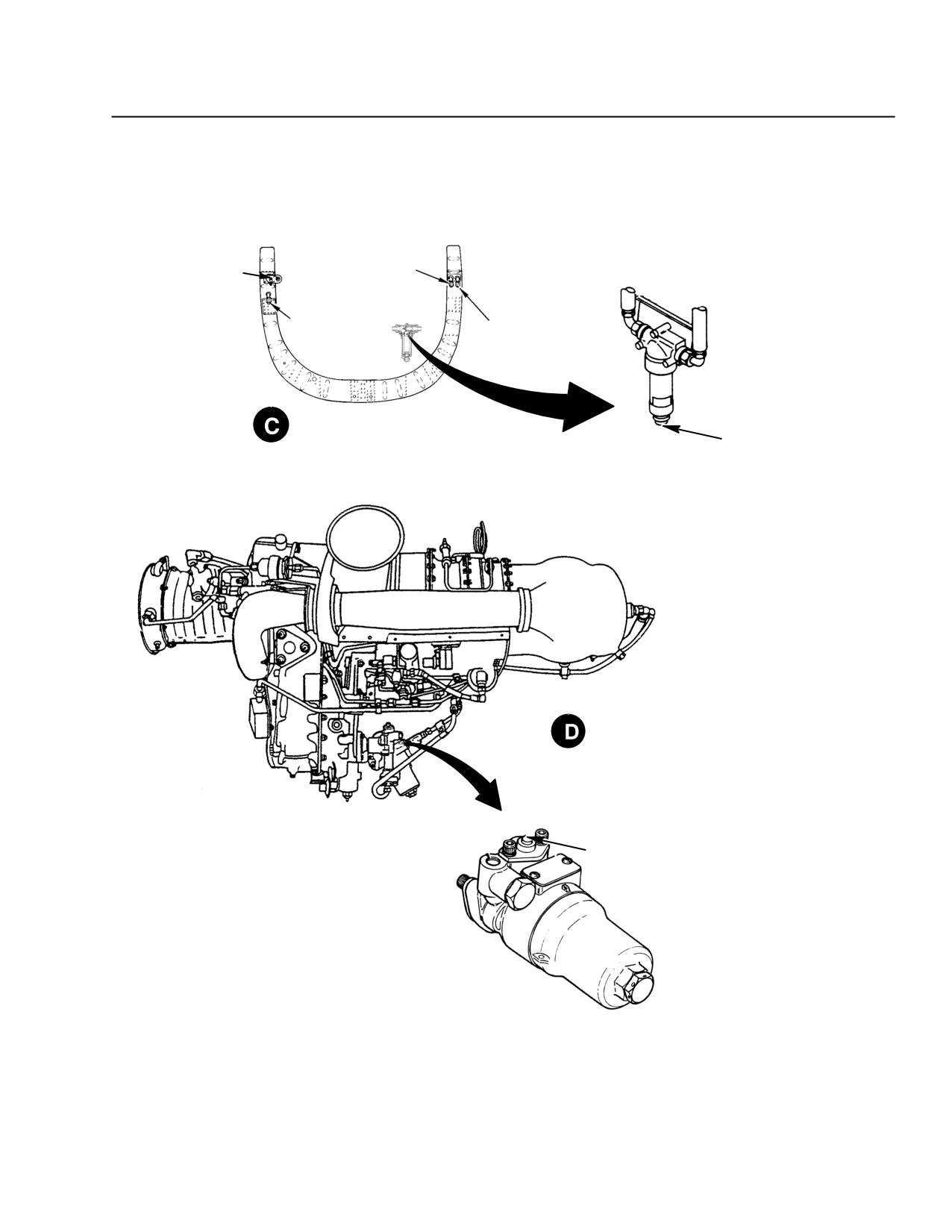
MD 500E
ROTORCRAFT FLIGHT MANUAL
CSP-E-1
(Model 369E)
Handling, Servicing,
and Maintenance
ENGINE WASH
ENGINE OIL
FITTING
TANK DRAIN
MAIN TRANSMISSION
OIL COOLER DRAIN
ENGINE OIL
COOLER DRAIN
STATION 137.50 BULKHEAD
BYPASS INDICATOR
SCAVENGE OIL FILTER
250-C20/R2 SP ENGINE
BYPASS INDICATOR
ENGINE FUEL FILTER
F03-031-2
Figure 7-4. Servicing Points (Sheet 2 of 2)
Revision 18
7-13
CSP-E-1
ROTORCRAFT FLIGHT MANUAL
MD 500E
(Model 369E)
Handling, Servicing,
and Maintenance
7-8. FUEL SYSTEM - SERVICING
Refueling vehicle should be parked a minimum of 20 feet from helicopter dur-
ing fueling operation.
Before starting fueling operation, always ground fueling nozzle or fuel truck to
GROUND HERE receptacle (Ref. Figure 7-4) or to another bare metal location.
Comply with the following precautions when servicing the fuel system.
Turn off electrical switches and disconnect any external power from
WARNING
helicopter. Electrically ground helicopter prior to refueling or
defueling. Static discharge spark in presence of fuel vapors can
cause fire or an explosion.
Cold weather fuels:
Grade JP-4 (MIL-T-5624), grade JP-5, and grade JP-8 (MIL-T-3133A, or
later) type fuels contain anti-ice additive which conforms to MIL-1-27686
(or later). These fuels do not require additional anti-ice additive.
Cold weather fuel mixtures
To assure consistent starts at temperatures at or below 4°C (40°F), a
mixture of AVGAS and jet fuels (other than JP-4 or Jet B) may be used.
The alternate avgas-jet fuel mixture is not recommended for warm
weather operation.
Refer to Allison Operation and Maintenance Manual for additional cold
weather fuel mix and blending instructions.
Filling:
The fuel system has two fuel cells that are interconnected for simultaneous
flow and venting.
Refuel the helicopter with the proper fuel as soon after landing as possible
to prevent moisture condensation.
Keep fuel nozzle free of all foreign matter.
Fuel tank servicing is through the cell filler neck on the right side of the
fuselage. The right side fuel cell contains the gravity filler port and cap.
Check filler cap for security after refueling.
7-14
Revision 18
MD 500E
ROTORCRAFT FLIGHT MANUAL
CSP-E-1
(Model 369E)
Handling, Servicing,
and Maintenance
Fuel draining:
Fuel draining should be accomplished with helicopter as level as possible.
The fuel system may be defueled in two ways: One is to defuel through the
filler port, using a pump. The other method is to open the drain valve on
fuselage underside.
The fuel cell drain valve is spring-loaded closed and is opened by depress-
ing an internal plunger.
After defueling, be sure to check drain valve for leakage.
7-9. ENGINE OIL SYSTEM - SERVICING
The engine oil tank filler is on the right side of the helicopter (Ref.
Figure 7-4). A liquid level sight gauge for checking oil level in tank is visible
through a transparent window near the filler.
NOTE: Oil level should be checked within 15 minutes after shutdown.
Replenish with correct oil until oil level is FULL on sight gauge.
CAUTIONDO NOT use Mobil SHC 626 oil in the engine oil system.
Make certain that oil tank filler cap is secured after servicing.
7-10. MAIN ROTOR AND TAIL ROTOR TRANSMISSION - SERVICING
Main rotor transmission:
Check transmission oil level at liquid level sight gauge (Ref. Figure 7-4)
NOTE: Indicated oil level may be incorrect if aircraft is not level or has been ground
handled in a tail-low attitude since last flight.
Replenish with correct oil until oil level is at the dashed lines above the
ADD mark on sight gauge.
Mixing of oils within an oil series, not in the same group, is not rec-
CAUTION
ommended. If oils of different groups are mixed, flush and re-ser-
vice gearbox. Mixing of oils from different series is prohibited.
NOTE: If oil was drained from transmission cooler, ground run helicopter for 15 minutes
after replenishing with oil and recheck oil level at sight gauge. Replenish oil as
necessary. This purges air from the oil cooling system and ensures that entire
oil cooling system is full.
Fill main transmission by lifting breather-filler cap and inserting funnel
into opening. Check that spring-loaded cap closes when funnel is removed.
Revision 18
7-15
CSP-E-1
ROTORCRAFT FLIGHT MANUAL
MD 500E
(Model 369E)
Handling, Servicing,
and Maintenance
Tail rotor transmission:
A liquid level sight gauge for checking oil level is located on the rear of the
transmission housing.
Check oil level by viewing sight gauge.
Servicing of the tail rotor transmission should be performed by maintenance
personnel.
7-11. CLEANING GENERAL
General cleaning of oil and dirt deposits from the helicopter by using dry-
cleaning solvent, standard commercial grade kerosene or a solution of deter-
gent soap and water.
Exceptions that must be observed are specified in the following cleaning para-
graphs.
Some commercial cleaning agents, such as readily available
CAUTIONhousehold cleaners, contain chemicals that can cause corrosive
action and/or leave residue that can result in corrosion. Examples
of cleaning agents that are not to be used are ‘‘Fantastic’’ and ‘‘409’’
type cleaners, or locally made strong soap cleaners.
7-12. CLEANING FUSELAGE INTERIOR TRIM AND UPHOLSTERY
Clean dirt or dust accumulations from floors and other metal surfaces with
vacuum cleaner or small hand brush.
Sponge soiled upholstery and trim panels with a mild soap and luke-warm wa-
ter solution. Avoid complete soaking of upholstery and trim panels. Wipe solu-
tion residue from upholstery with soft cloth dampened with clean water.
Remove imbedded grease or dirt from upholstery and carpeting by sponging or
wiping with an upholstery cleaning solvent recommended for the applicable
fabric (nylon, vinyl, leather, etc).
NOTE: If necessary, seat upholstery may be thoroughly dry-cleaned with solvent. When
complete dry cleaning is performed, upholstery must be re-flameproofed to
comply with Federal Aviation Regulation Part 27.
7-16
Revision 18