Rolls-Royce Engine 250–C18, 250–C18A, 250–C18B, 250–C18C. Operation and Maintenance Manual (2003) - page 3
CAUTION: WHEN MIXING THE FUELS, AVOID HIGH FLOW RATES. DO NOT EXCEED A
FLOW RATE OF 50 GALLONS PER MINUTE. ALSO, MAKE SURE THE FUEL
NOZZLE AND FUEL TANK ARE GROUNDED TO THE AIRCRAFT.
(1) Make the fuel mix in the aircraft tank. The AVGAS can be added before or after the jet fuel,
the only restriction is that the final mix (including fuel in the tank before starting the mix) be two
parts by volume jet fuel to one part by volume AVGAS.
NOTE: Anti-ice additive is needed for the jet fuel-AVGAS fuel mixture unless qualified in
accordance with para 10 A. (Refer to Section 1, Fuel Specifications.)
(a) The alternate fuel mixture is not recommended for warm weather operation. It is
recommended only when the ambient temperature is below 4°C (40°F).
WARNING: HANDLING LEAD RESIDUE COATED PARTS BY PERSONS WITH OPEN
CUTS OR SCRATCHES ON THEIR HANDS CAN BE EXTREMELY
DANGEROUS. ALWAYS WEAR GLOVES WHEN CHECKING RESIDUE
COATED TURBINE OR EXHAUST PARTS.
(b) When the AVGAS-jet fuel mixture is used in the engine the lead from the gasoline
accumulates on the turbine and exhaust collector outlet ducts. The normal appearance
after operation on leaded fuel is a pale yellow powder deposit on the exhaust surfaces.
B.
In order to obtain a lightoff when the alternate fuel mixture is made in the fuel tank. it may be
necessary to:
(1) Preheat the engine, or
(2) Bleed the unmixed fuel
CAUTION: DO NOT USE AN OPEN FLAME HEATER TO PREHEAT THE ENGINE.
(3) Preheat the engine in the area of the fuel control.
CAUTION: POST FIRE PROTECTION BEFORE OPENING THE FUEL LINE.
(4) Bleed the unmixed fuel from the system as follows:
(a) Deactivate the igniter circuit breaker.
WARNING: BE AWARE OF THE POTENTIAL FIRE HAZARD OF FUEL IN AN OPEN
CONTAINER.
(b) Position the fuel line in a container. Observe caution to keep contaminants from entering
the exposed fuel passage.
(c) Turn on the aircraft boost pump. Open the throttle. Continue the flow from the fuel line
until the unmixed fuel has drained and the AVGAS mixture appears. The AVGAS mixture
can be visually detected because it is light pink in color.
(d) Close the throttle. Turn off the boost pump. Reconnect the fuel line to the fuel nozzle.
Torque the coupling nut to 80-120 lb in. (9.0-13.6 N@m).
(e) Close the igniter circuit breaker.
12.
Cold Weather Oils
If ambient temperatures are below -40°C (-40°F) or MIL-PRF-23699 oils are not available, use
MIL-PRF-7808 oils.
13.
Time Between Overhauls (TBO’s)
The model 250 engine was originally designed to permit module overhaul. The major components of the
engine are the compressor, gearbox, and turbine. A premature removal of any of these components
should not cause removal of the other components unless secondary damage has occurred.
Page 15
14. Engine TBO’s
For Operators that do not wish to utilize the sectionalized overhaul concept, Rolls-Royce Engine
Company recommends a Time Between Overhauls of 1250 hours for Blue Ribbon 250-C18 Series
engines provided that the turbine incorporates increased cooling (identified by the letters ‘BC’ following
the turbine serial number). For Blue Ribbon engines not incorporating the increased cooling turbine,
recommended TBO is 1250 hours, provided that the 1st-stage turbine wheel is replaced prior to
exceeding 750 hours wheel total time. Recommended TBO on non-Blue Ribbon engines is 750 hours.
These TBO’s apply only if the engine conforms to the requirements of Table 3. Conformance is to be
determined by engine log book entry or production conformance per Section Table 3.
TABLE 3
250-C18 Configuration Requirements
Requirement
250-C18 Production Effectivity
250-C18A Production Effectivity
Compressor tiebolt hardness
Compressor S/N CAC 20095,
Compressor S/N CAC 20177 and
CAC 20101, and up conform
up conform
Engine S/N CAE 80010 and up
Engine S/N CAE 800177 and up
conform
conform
Compressor impeller web thick-
Engine S/N CAE 800129 and up
Engine S/N CAE 800177 and up
ness check
conform
conform
Compressor front (No. 1) bearing
Engine S/N CAE 800129 and up
Engine S/N CAE 800177 and up
separator has rivets of the proper
conform
conform
material
The compressor front (No. 1)
Compressor S/N CAC 20128,
Compressor S/N CAC 20177 and
bearing vibration damper complies
CAC 20129, CAC 20132, CAC
up conform
with ATW-980
20135, and up conform
The compressor front (No. 1)
Engine S/N CAE 800129 and up
Engine S/N CAE 800177 and up
bearing vibration damper complies
conform
conform
with ATW-980
2nd-stage turbine wheel complies
Turbine S/N CAT 20085 and up
Turbine S/N CAT 20177 and up
with CW-28
conform
conform
Engine S/N CAE 800083 and up
Engine S/N CAE 800177 and up
conform
conform
15. Modular TBO
For operators who wish to utilize modular overhaul, Rolls-Royce Engine Company recommends time
between overhauls as listed in Tables 4 and 5.
16. On-Condition Parts
A. The accessories and components that are on-condition are listed in Table 6.
B. Operating hours with respect to maintenance records means the time from the moment an aircraft
leaves the surface of the earth until it touches at the next point of landing.
Page 16
TABLE 4
Modular Overhaul-Components Recommended Time Between Overhaul
Component
TBO Hours
Blue Ribbon Compressor (identified by the letter ‘B’ after the compressor serial number on
1750(1)
the compressor identification plate)
Non-Blue Ribbon Compressor
750(1)
Gearbox
On Condition
Product Improved Turbine (identified by the letter ’P’ after the turbine serial number on the
1250(1)(3)
turbine identification plate)
Blue Ribbon Turbine with increased cooling (identified by the letters ‘BC’ after the turbine
1250(1)(3)
serial number on the turbine identification plate)
Blue Ribbon Turbine (identified by the letter ‘B’ after the turbine serial number on the turbine
1250(1)(2)
identification plate)
Non-Blue Ribbon Turbine
750(1)(2)
(1) Refer to Table 7 for life limits on certain rotating parts. It is the responsibility of the operator to assure that
life limits are never exceeded.
(2) Requires replacement of the 1st-stage turbine wheel prior to exceeding 750 hours wheel total time.
(3) 1st-stage turbine wheels in these turbines have a 1550-hour life limit, providing that the wheels have not
been operated in a non-increased cooling configuration turbine.
TABLE 5
Accessories Recommended Time Between Overhauls (Hours)
Component
Recommended TBO Hours
Fuel Pump
Sundstrand (Pesco) Dual Element
1500(1)
Sundstrand (Pesco) Dual Element
2250(2)
Sundstrand (Pesco) Single Element
2250
Argo-Tech (TRW) PN 386500-5 (6899253)
4000
PN 386500-1, -2, -3, and -4
3500
Chandler Evans (CECO)- P/N 113300-01A1 (Rolls-Royce P/N 23057338)
3500
- P/N 113300-02A1 (Rolls-Royce P/N 23065132)
- P/N 113300-03A1 (Rolls-Royce P/N 23070459)
Blue Ribbon Fuel Control Bendix P/N
1500
2524463-2
2524463-3
2524463-4
2524527-2 and later
Non-Blue Ribbon Fuel Control
750
Blue Ribbon Governor
1500
Bendix P/N
2524464-1
2524528-2 and later
Non-Blue Ribbon Governor
750
Fuel Nozzle
1250
Page 17
May 15/00
TABLE 5
Modular Overhaul-Components Recommended Time Between Overhaul - continued
Component
Recommended TBO Hours
Non-Blue Ribbon Double Check Valve
750
Bleed Valve
1250
WARNING: MANDATORY COMPLIANCE DATE FOR 250-C18 CEB-161 WAS AUGUST 30, 1980.
(1)
P/N 6854292, 6857548, 6877719, 6856250 and 6876803 not complying with Rolls-Royce
Commercial Engine Bulletin 250-C18 CEB-161.
(2)
Component pumps which have complied with 250-C18 CEB-161.
TABLE 6
On-Condition Accessories and Components(1)
Accessories and Components
Accumulators (Fuel System Pneumatic)
Anti-ice Valve
Burner Drain Valve
Combustion Liner
Compressor Discharge Air Tubes
Fuel System Check Valve
Igniter Lead
Igniter Plug
Ignition Exciter
Outer Combustion Case
Pc Air Filter
Tubes and Hoses (Fuel, Lube and Air)
Turbine Oil Check Valve
Double Check Valve
(1) May remain in service provided operation and condition is satisfactory. Refer to Section III, Inspection
Checksheet, Table 8 and Special Inspections, Table 9 for inspection requirements.
17. Life Limited Parts
CAUTION: OPERATORS ARE REQUIRED BY THE FAA TO COMPLY WITH THE PARTS LIFE
LIMITATIONS INDICATED HEREIN. IT IS THE RESPONSIBILITY OF THE OPERATOR
ALONE TO MAINTAIN A RECORD OF HOURS. IT IS ESSENTIAL THAT TOTAL TIME
OF APPLICABLE COMPONENTS BE RECORDED IN THE PART I SERVICE RECORD
PAGES FOR BOTH THE COMPRESSOR ASSEMBLY AND TURBINE ASSEMBLY.
FAILURE TO RECORD HOUR DATA OF APPLICABLE PARTS IN THE LOG BOOK
WILL RESULT IN THOSE PARTS BEING REPLACED AT THE OPERATOR’S EXPENSE
WHEN ENGINES OR COMPONENTS ARE RETURNED FOR OVERHAUL. (REFER
TO PARA 18, LOG BOOK ENTRIES FOR AN EXPLANATION OF LOG BOOK ENTRIES
PERTAINING TO HOUR RECORDS ON LIFE LIMITED PARTS.
Page 18
NOTE: All Life Limited Parts removed from a type certificated product must be tagged to identify
the part. The tag or record must include the part number, serial number and current life
status of the part, hours, and cycles. Each time the part is removed, either a new tag or
record must be created, or the existing tag or record must be updated with the current life
status of the part. The tag or record must remain with the part at all times when not
installed.
When a life limited part is removed from service due to meeting the published life limits,
vibropeen or etch the words “life expired” next to or under the part number. A life limited
part, other than new (however, proper paper work to provide traceability is still required),
must have a tag or record attached.
A. Table 7 contains FAA approved life limitations for those engine parts that are life limited.
(1) Life limits of parts are based on total hours.
(2) Operating hours with respect to maintenance records means the time from the moment an
aircraft leaves the surface of the earth until it touches at the next point of landing.
TABLE 7
250-C18 Component Parts Life Limits
Nomenclature
Part No.
Description
Max Opera-
Maximum
tion Hours
Cycles
COMPRESSOR ROTOR ASSEMBLY
Impeller Assembly
6854131, that have not
Original
1700
----
complied with 250 DIL-74(1)
6851116, that have not
Removable labyrinth seal
1700
----
complied with 250 DIL-74(1)
6854131, that have complied
Original
2000
----
with 250 DIL-74 (1)
6851116, that have com-
Removable labyrinth seal
2000
----
plied with 250 DIL-74 (1)
6876367
Hub relocated rearward
3050
----
6876934
Hub relocated rearward
2500
----
GAS PRODUCER TURBINE ROTOR ASSEMBLY
1st-Stage Wheel
6852171
Original
750(4)
----
6852171
Original
1550(2)
----
6859661
Solution heat treated
750
----
6859661
Solution heat treated
1550(2)
----
6886407
Thick rim
1550(3)
----
2nd-Stage Wheel
6850035
Intergral balance piston
100(3)
----
seal knives
6856082
Balance piston seal knives
100(3)
----
deleted
6857912
Increased thickness web
1550
----
6871872
Increased air flow area
1550
----
6877092
Changed contour
1550
----
Page 19
TABLE 7 (cont)
Nomenclature
Part No.
Description
Max Opera-
Maximum
tion Hours
Cycles
6898782
Pilot diameter
1550
----
Gas Producer
23068265
Thick Design
----
9000
Turbine Tie-Bolt
POWER TURBINE ROTOR ASSEMBLY
3rd-Stage Wheel
6843393
Original
2500
----
6859663
Solution heat treated
2500
----
4th-Stage Wheel
6847449
Original
2500
----
6859664
Solution heat treated
2500
----
1) Compliance with Rolls-Royce Distributor Information Letter, 250 DIL-74, can be determined from the Log
Book. Also, impellers that have complied are identified by DIL-74I or DIL-74R etched after the serial number.
250 DIL-74 applies to impellers prior to S/N 19000 (serial number will be preceded by the prefix BP, C, BU, BL,
or H).
(2) 1st-stage wheels operated in Blue Ribbon turbines incorporating increased cooling (identified by letters ’BC’
or “P” following the turbine serial number) have a life limit of 1550 hours, providing that the wheels have not been
operated in a non increased cooling configuration turbine. Remove from service by April 30,1982.
(3)
1st-stage wheels operated in Blue Ribbon turbines incorporating increased cooling (identified by letters
‘BC’ or ‘‘P” following the turbine serial number) have a life limit of 1550 hours, providing that the wheels have
not been operated in a non increased cooling configuration turbine.
(4) DO NOT install either new or used PN 6850035 or 6856082 2nd-stage turbine wheels.
(5) Remove from service.
WARNING: IT IS NOT ALLOWED, TO INSTALL A TURBINE WHEEL WITH ACCEPTABLE WHEEL RIM
CRACKS IN ANY ENGINE/TURBINE DURING OVERHAUL. ACCEPTABLY CRACKED
TURBINE WHEELS MAY BE REINSTALLED ONLY DURING A TIME CONTINUED
ENGINE/TURBINE REPAIR.
NOTE:
1st-stage turbine wheels with acceptable wheel rim cracks which have been inspected and
approved for time continued use in accordance with the overhaul manual (for a repaired engine
or turbine) may be continued in service to overhaul or an additional 500 hours (provided the
listed part hour limit is not exceeded).
NOTE:
2nd-stage turbine wheels with acceptable wheel rim cracks which have been inspected and
approved for time continued use in accordance with the overhaul manual (for a repaired engine
or turbine) may be continued in service to overhaul or completion of the wheel’s maximum
hour life limit.
18. Log Book Entries
CAUTION: WHENEVER A COMPRESSOR OR TURBINE IS PLACED IN SERVICE, THE
CURRENT OPERATING HOURS ON THE LIFE LIMITED PARTS SHOULD BE
REVIEWED AND COMPARED WITH THE MAXIMUM LIMITS SPECIFIED.
A. Maintenance of the Total Time Records is the operator’s responsibility. This information appears in
the Part V, Assembly Record of the Turbine and Compressor Log Book pages.
B. Make appropriate entries regarding removal in the applicable Part I, Service Record page.
NOTE: Be sure to return all turbine or compressor pages of respective components with the
components at time of overhaul or repair.
Page 20

19.
Trend Check Procedure
A. Description
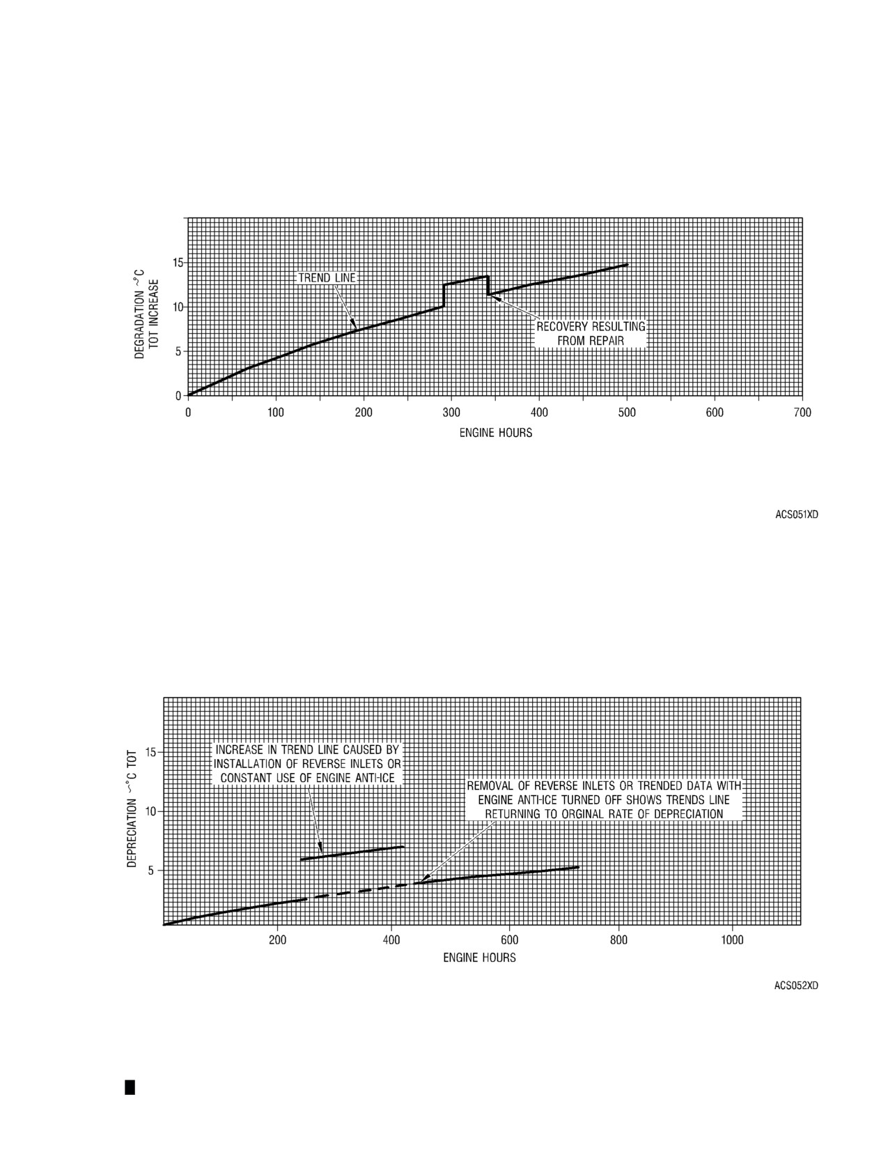
(1) Trend checks can be used to monitor the health of the engine on a day to day basis. However,
trending is best used to determine engine health over longer periods of sustained operation.
The key to interpreting the data is a basic understanding of the engine characteristics. Turbine
engines normally degrade or lose power through engine operation. If normal degradation is
plotted against accumulated engine hours, the trend line of increased turbine outlet
temperature (TOT) could appear as in FIG. 4.
NOTE: FIG. 4 through 8 and 18 are for a typical engine. The degradation trend plotted for a
specific engine should follow the general pattern of these curves; but, need not
duplicate the illustrated values.
(2) Degradation is also affected by operation in erosive environments, excessive operation at high
temperature or overtemperature conditions, and other abnormal conditions. The more erosive
the environment, the longer the high temperature was maintained or the higher the
overtemperature, the faster performance will degrade. Degradation due to this type of
abnormal operation could appear as the trend line depicted in FIG. 5.
(3) Short term degradation can be caused by operating the engine in contaminated atmospheric
conditions. Dust, smoke, and other industrial contaminants can cause this type of power loss.
Aircraft oil leaks, when they mix with the air entering the engine, can also result in a loss of
power. This type of degradation can take place in minutes or hours and is generally corrected
by rinsing or washing the engine. Following the engine rinse or wash, it is normal that power
would return to the previous baseline. If power is not recovered following a rinse or wash of a
dirty engine, another problem is indicated.
Normal Engine Degradation
FIG. 4
Page 21
(4) Engine components that are in the process of failing can also appear as short term
degradation. When engine performance degrades over a short period of time, and rinsing or
washing the engine doesn’t recover the performance loss, a component failure or
misadjustment should be investigated and corrected. Following maintenance it would be
normal to expect that trend line power would be recovered. This type of component failure or
loss of adjustment could appear as in FIG. 7.
(5) FIG. 4 through 7 represent some of the typical data plots that can result when attempting to
analyze trended data. There are numerous combinations of these graphs that when properly
analyzed can provide the operator useful information to determine that maintenance is, or soon
will be, required. However, interpreting the data is not always a straight forward process.
There are a number of factors that occur to confuse or mask both normal and abnormal
readings.
WARNING: DO NOT EXCEED SPECIFIED AIRCRAFT OR ENGINE LIMITATIONS DURING
PERFORMANCE OF THIS CHECK.
(6)
Data scatter and pilot procedure can be a common source of inaccuracy in the trend
procedure. It can result from the normal instrumentation error caused by allowable
inaccuracy/readability or omission/change of a trend check procedure step. Following the daily
flight trend check, the recorded data should be corrected and plotted. When the corrected
TOT readings are more than plus or minus 20°C from the existing trend line, maintenance
personnel should make sure no obvious failures have occurred before repeating the trend
check to determine whether the variation was due to data scatter or pilot procedure. If, upon
repeating the trend check, the newly plotted data returns to within plus or minus 20°C from the
existing trend line without further action by the pilot or maintenance personnel, the problem
was probably due to data scatter. Neither the aircraft nor engine should have to be operated
beyond established limitations to perform the trend check procedure. If aircraft or engine
limitations are encountered during performance of the trend check procedure, it is an indication
that the check has either been improperly performed or that there is an aircraft or engine
problem.
NOTE: Prior to initiating a trend check program, operators should assure that the aircraft
instrumentation is properly calibrated.
(7)
When engine performance degrades beyond the limits allowed in applicable aircraft
publications, maintenance should be performed. Each time that engine maintenance is
performed, some measure of performance may be recovered. Normally, following this
maintenance, the engine will not recover to the power level experienced when the engine was
new or overhauled, without the replacement or rework of components to like new condition.
FIG. 5 shows a typical performance recovery resulting from regular engine washes. Note that
engine performance does not return to the original baseline power available when the engine
was new or overhauled.
(8)
If repeated checks continue to give corrected plotted readings in excess of plus or minus 20°C
corrected TOT change from the existing trend line, the cause can also be due to pilot
procedure. Each step of the procedure should be reviewed to assure that all switches were
properly positioned and instruments were read correctly. One of the most common causes for
inaccuracy is leaving the anti-ice, bleed air heater, environmental control unit or other engine
air-operated component turned on during the check. Also be sure to allow the engine at least
1 minute to stabilize prior to taking any readings. If the procedure was performed correctly and
the plus or minus 20°C (68°F) corrected TOT change continues to result, then an aircraft or
engine problem should be investigated.
Page 22

Abnormal Operation Engine Degradation
FIG. 5
Performance Recovery Due to Engine Wash
FIG. 6
Page 23
(9) To assure accurate trend checks, the aircraft configuration must remain the same during the
first and each subsequent check. For example, some aircraft have bleed air operated
components such as pumps that cannot be turned off. Since each trend check would be made
with these systems operational, it will have no visible effect on the trended data. Additionally, if
an engine operated subsystem was usually required for safe flight during the period the trend
check was normally performed, the first and each subsequent check should be performed with
that system operational. For example, in some areas of the world, engine anti-ice is
frequently required for normal operation and should therefore be operated during each trend
check. Furthermore, when a new or overhauled engine, or an aircraft or engine component
that may affect performance is installed, a new baseline trend must be established. A change
in the trend line could appear as in FIG. 8.
B.
Example
(1)
This example is provided to illustrate data tabulation, correction, and graphing.
(a)
Aircraft flight condition:
2,000 feet pressure altitude, 20°C outside air temperature, 100
knots airspeed with the following engine instrument indications: N1 = 98%, N2 = 100%,
Torque = 80%, TOT = 720°C, Oil Pressure = 110 psig, Oil Temperature = 95°C.
(b)
The maintenance or operations section shall record aircraft S/N, engine S/N, date, and
engine time on the 250 Trend Check Record. (Ref. FIG. 9)
(c)
After departure, the pilot notes the correct altimeter reading, sets the altimeter to 29.92 in.
Hg and continues to climb the aircraft to 2000 ft pressure altitude.
NOTE: Any 1,000 foot increment in pressure altitude up to 10,000 feet can be selected
for the check. However, data reduction is simplified when the same pressure
altitude is used for each subsequent check.
NOTE: Any baseline torque that provided an indicated N1 speed greater than 95% can
be utilized. The indicated torque setting required will be obtained from the
torque correction chart by entering the chosen baseline torque and pressure
altitude to be flown.
(d)
The pilot now adjusts the engine power for cruise flight at 80% torque, checks that the N1
is above 95% and waits for one minute to allow the engine to stabilize. The pilot now
records PA = 2000 ft, TOR = 80%, OAT + 20°C, N1 = 98% and TOT = 720°C on the 250
Trend Check Record. (Ref. FIG. 10) Since light to moderate turbulence was experienced
throughout the procedure, the pilot has noted “turbulence” in the remarks block to indicate
that the data might be affected. The pilot then resets the altimeter to the correct reading.
(e)
Following flight, the recorded data can be corrected and trended. The baseline
parameters for the graphed data are 2,000 feet pressure altitude and 80% indicated
torque. After determining that these baseline parameters have been used, the resulting
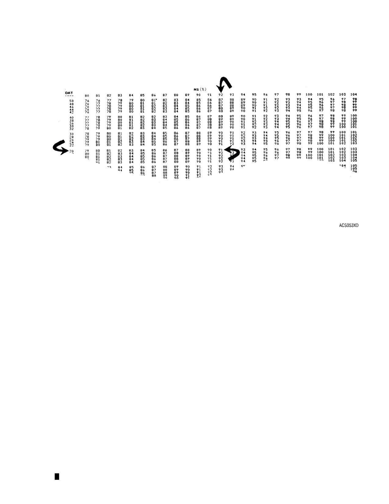
data can be corrected and graphed. Using FIG. 11, determine the corrected N1 speed
value. Find the indicated OAT on the left vertical scale and the indicated N1 speed on the
top horizontal scale. Moving right and down, you will intersect at the corrected N1 speed
of 91%. Graph this speed as indicated in FIG. 13.
NOTE: If the pilot cannot utilize the same baseline pressure altitude for each trend
check, the trend procedure must be modified. The use of a nonstandard
altitude described in sub-para h will allow the pilot to perform the trend check at
various altitudes.
(f)
Using FIG. 12, determine the corrected TOT. Find the indicated OAT on the left vertical
scale and indicated TOT on the top horizontal scale. Moving right and down, you will
intersect at the corrected TOT value of 624°C. For indicated TOT values over 650°C,
consult the second page of Table 10. Graph this data as indicated in FIG. 13.
Page 24
Engine Degradation with Component Failure/Repair
FIG. 7
Engine Degradation Baseline Change
FIG. 8
Page 25

Example -- Data Filled in by Maintenance/Operations
FIG. 9
Example -- Data Added By the Pilot
FIG. 10
Page 26
N1 Correction Chart
FIG. 11
(g) It should be noted that the data graphed in FIG. 13 can not always be directly compared
to the background data depicted in FIG. 4 through 8. The background data is for
illustration purpose only to show long term degradation of a typical engine. Actual
graphed N1 and TOT data can vary from the example. The important thing to remember
is that the overall trend should be gradual. Step changes in the trend are significant and
their causes should be determined.
(h) If a baseline pressure altitude for performing the daily trend check procedure cannot be
established, the check can still be completed by correcting the torque input value to sea
level conditions prior to performing the check. (Ref. FIG. 14) For example, if flight
clearance is to climb and maintain 3000 feet, enter the chart at the baseline torque value
of 80% torque, move right to intersect the 3000 foot pressure altitude value and read 72%
torque as depicted. Accordingly, for this flight set the 72% on the aircraft torque gage,
record the readings, correct the data and plot the values as described earlier. The use of
a different baseline altitude for each check will require the torque correction chart depicted
in FIG. 14 to be carried in the aircraft for reference.
(i)
Reduced torque values may be required at high altitudes to remain within engine or
aircraft limitations. This can result in N1 readings below 95% speed that will allow the
engine bleed valve to open. If this data is plotted, it will erroneously appear as a step
change increase in the TOT trend. Step change increases in the TOT trend must be
compared to the trended N1 to assure the bleed valve is closed. Data taken while the
bleed valve is fully open or modulating will not be accurate.
Page 27

TOT Correction Chart
FIG. 12
(j)
Step change variations in TOT or other graphed parameters should be investigated to
determine their cause. Step changes that result from aircraft configuration changes,
engine maintenance or other known causes are permissible and result in a new trend line
as illustrated in FIG. 7 or 8. Step changes resulting from unknown causes should be
investigated systematcally using the recommendations provided in the troubleshooting
section of this manual. (See Section III, Table 6, Engine Troubleshooting.)
(k) The maximum amount of deterioration allowed is determined by the limits stated in the
aircraft flight manual and in accordance with the aircraft manufacturer’s FAA approved
power assurance check procedure.
20.
Procedure
A. Set the aircraft altimeter to 29.92 in. Hg and fly the aircraft at a pressure altitude convenient to
normal flight and in increments of 1000 feet from sea level. The maximum altitude for the check is
10,000 ft. Ensure the following conditions exist:
WARNING: DO NOT TURN OFF SYSTEMS OR COMPONENTS REQUIRED FOR SAFE FLIGHT.
IF ANTI-ICE IS FREQUENTLY REQUIRED FOR SAFE FLIGHT, IT SHOULD BE
OPERATED DURING EACH TREND CHECK.
(1) Anti-ice air - off
(2) Environmental control unit - off
(3) Bleed air heater - off
(4) Generator load is less than 20%
Page 28
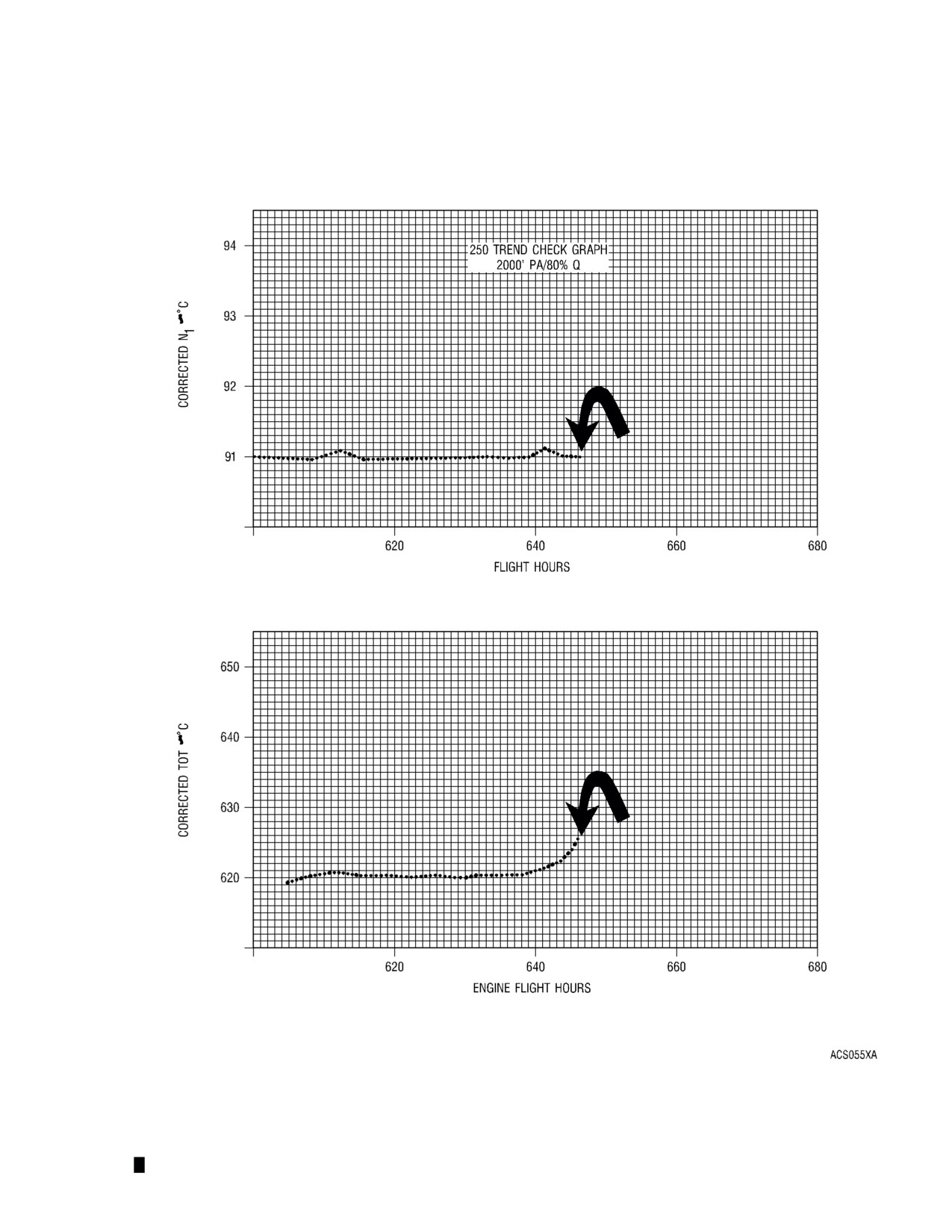
Trend Check Graph
FIG. 13
Page 29

Torque Correction Chart
FIG. 14
B.
Set engine N2 speed at Normal Cruise rpm. This speed should remain constant on all subsequent
checks.
NOTE: If N2 rpm is changed for subsequent checks, a new baseline trend will be established.
(1)
Keep the aircraft in a level cruise flight when this trend check is performed. Do not perform the
check while in a climb or descent flight mode.
(2)
Set the engine power to a baseline torque value that provides at least 90% N1 speed to ensure
the engine bleed valve is closed and to ensure a valid trend check. If a nonstandard baseline
altitude is used, determine the indicated torque requirement from the torque correction chart.
(See Table 8.) If N1 is not 90% or more, sub-para (1 ) should be repeated at a higher torque
value which will also establish a new trend line. Hold cruise power for one minute to allow the
engine to stabilize prior to recording the data listed in sub-para (3).
(3)
Record the following values on the trend check record form provided as FIG. 15.
(a) Pressure altitude
(b) OAT °C
(c) N1 -- Gas Producer rpm
(d) Torque
(e) Turbine Outlet Temperature -- TOT
(4)
Following flight, correct N1, TOT, and torque values using the charts provided in Tables 8
through 10. Record corrected values on the trend check graph provided in FIG. 16.
NOTE: Refer to FIG. 17 for a reference outline of the trend check procedure which can be
conveniently carried in the aircraft.
Page 30

TABLE 8
Torque Correction Chart - Pressure Altitude (ft)
Baseline
Sea
Torque
Level
1000
2000
3000
4000
5000
6000
7000
8000
9000
10,000
Indicated Torque
60
60
58
56
54
52
50
48
46
45
43
41
65
65
63
60
58
56
54
52
50
48
46
45
70
70
68
65
63
60
58
56
54
52
50
48
75
75
72
70
67
65
62
60
58
56
54
52
80
80
77
74
72
69
67
64
62
59
57
55
85
85
82
79
76
73
71
68
66
63
61
58
90
90
87
84
81
78
75
72
69
67
64
62
95
95
92
88
85
82
79
76
73
71
68
65
100
100
96
93
89
86
83
80
77
74
71
69
NOTE: Depending on aircraft gross weight and ambient conditions, performance of the trend check may not be
possible using some of the above indicated torques if the trended torque FIG. selected produces an indicated
torque value that is so low that an accurate trend check is not possible, an increased baseline torque value may
be required.
250 TREND CHECK RECORD
AIRCRAFT S/N
ENGINE S/N
Date
Engine Time
Pressure
TORQ.
OAT
N1
TOT
Remarks
Altitude
Trend Check Data Recording Form
FIG. 15
21. Aircraft Manufacturer Trend Check -- Alternate Procedure
Most aircraft manufacturer power checks generate percent torque as part of the aircraft In-flight Power
Assurance -- Daily Trend Check. This procedure trends power or torque with appropriate corrections
for ambient flight conditions and aircraft installation characteristics. The result of this procedure is Delta
percentage of specifications torque. This Delta percentage of specification torque can be used for trend
monitoring by plotting the observed torque margin on a daily basis. This plot would appear similar to
FIG. 15.
Page 31
TABLE 9
N
1 Correction Chart
N1%
OAT
80
81
82
83
84
85
86
87
88
89
90
91
92
93
94
95
96
97
98
99
100
101
102
103
104
50
76
76
77
78
79
80
81
82
83
84
85
86
87
88
89
90
91
92
93
93
94
95
96
97
98
48
76
77
78
79
80
81
81
82
83
84
85
86
87
88
89
90
91
92
93
94
95
96
97
98
99
46
76
77
78
79
80
81
82
83
84
85
86
86
87
88
89
90
91
92
93
94
95
96
97
98
99
44
76
77
78
79
80
81
82
83
84
85
86
87
88
89
90
91
92
92
93
94
95
96
97
98
99
42
76
77
78
79
80
81
82
83
84
85
86
87
88
89
90
91
92
93
94
95
96
97
98
98
99
40
77
78
79
80
81
82
82
83
84
85
86
87
88
89
90
91
92
93
94
95
96
97
98
99
100
38
77
78
79
80
81
82
83
84
85
86
87
88
89
89
90
91
92
93
94
95
96
97
98
99
100
36
77
78
79
80
81
82
83
84
85
86
87
88
89
90
91
92
93
94
95
96
97
98
98
99
100
34
77
78
79
80
81
82
83
84
85
86
87
88
89
90
91
92
93
94
95
96
97
98
99
100
101
32
78
79
80
81
82
83
84
85
86
86
87
88
89
90
91
92
93
94
95
96
97
98
99
100
101
30
78
79
80
81
82
83
84
85
86
87
88
89
90
91
92
93
94
95
96
97
97
98
99
100
101
28
78
79
80
81
82
83
84
85
86
87
88
89
90
91
92
93
94
95
96
97
98
99
100
101
102
26
79
79
80
81
82
83
84
85
86
87
88
89
90
91
92
93
94
95
96
97
98
99
100
101
102
24
79
80
81
82
83
84
85
86
87
88
89
90
91
92
93
94
95
96
97
97
98
99
100
101
102
22
79
80
81
82
83
84
85
86
87
88
89
90
91
92
93
94
95
96
97
98
99
100
101
102
103
20
79
80
81
82
83
84
85
86
87
88
89
90
91
92
93
94
95
96
97
98
99
100
101
102
103
18
80
81
82
83
84
85
86
87
88
89
90
91
92
93
94
95
96
96
97
98
99
100
101
102
103
16
80
81
82
83
84
85
86
87
88
89
90
91
92
93
94
95
96
97
98
99
100
101
102
103
104
14
80
81
82
83
84
85
86
87
88
89
90
91
92
93
94
95
96
97
98
99
100
101
102
103
104
12
80
81
82
83
84
85
86
87
88
89
90
91
92
93
94
95
97
98
99
100
101
102
103
104
105
10
81
82
83
84
85
86
87
88
89
90
91
92
93
94
95
96
97
98
99
100
101
102
103
104
105
8
81
82
83
84
85
86
87
88
89
90
91
92
93
94
95
96
97
98
99
100
101
102
103
104
105
6
81
82
83
84
85
86
87
88
89
90
91
92
93
94
96
97
98
99
100
101
102
103
104
105
106
4
82
83
84
85
86
87
88
89
90
91
92
93
94
95
96
97
98
99
100
101
102
103
104
105
106
2
82
83
84
85
86
87
88
89
90
91
92
93
94
95
96
97
98
99
100
101
102
103
104
105
106
0
82
83
84
85
86
87
88
89
90
91
92
93
94
96
97
98
99
100
101
102
103
104
105
106
107
–2
82
84
85
86
87
88
89
90
91
92
93
94
95
96
97
98
99
100
101
102
103
104
105
106
107
–4
83
84
85
86
87
88
89
90
91
92
93
94
95
96
97
98
99
100
101
102
103
105
106
107
108
–6
83
84
85
86
87
88
89
90
91
92
93
95
96
97
98
99
100
101
102
103
104
105
106
107
108
–8
83
84
85
87
88
89
90
91
92
93
94
95
96
97
98
99
100
101
102
103
104
105
106
107
108
–10
84
85
86
87
88
89
90
91
92
93
94
95
96
97
98
99
100
102
103
104
105
106
107
108
109
–12
84
85
86
87
88
89
90
91
92
93
95
96
97
98
99
100
101
102
103
104
105
106
107
108
109
–14
84
85
86
88
89
90
91
92
93
94
95
96
97
98
99
100
101
102
103
104
105
107
108
109
110
–16
85
86
87
88
89
90
91
92
93
94
95
96
97
98
100
101
102
103
104
105
106
107
108
109
110
–18
85
86
87
88
89
90
91
92
94
95
96
97
98
99
100
101
102
103
104
105
106
107
108
109
111
–20
85
86
87
89
90
91
92
93
94
95
96
97
98
99
100
101
102
103
105
106
107
108
109
110
111
–22
86
87
88
89
90
91
92
93
94
95
96
97
99
100
101
102
103
104
105
106
107
108
109
110
111
–24
86
87
88
89
90
91
92
94
95
96
97
98
99
100
101
102
103
104
105
106
108
109
110
111
112
–26
86
87
89
90
91
92
93
94
95
96
97
98
99
100
102
103
104
105
106
107
108
109
110
111
112
–28
87
88
89
90
91
92
93
94
95
96
98
99
100
101
102
103
104
105
106
107
108
110
111
112
113
–30
87
88
89
90
91
93
94
95
96
97
98
99
100
101
102
103
105
106
107
108
109
110
111
112
113
–32
87
89
90
91
92
93
94
95
96
97
98
99
101
102
103
104
105
106
107
108
109
110
112
113
114
–34
88
89
90
91
92
93
94
96
97
98
99
100
101
102
103
104
105
106
108
109
110
111
112
113
114
–36
88
89
90
91
93
94
95
96
97
98
99
100
101
103
104
105
106
107
108
109
110
111
112
114
115
–38
89
90
91
92
93
94
95
96
97
99
100
101
102
103
104
105
106
107
108
110
111
112
113
114
115
Page 32
TABLE 10
TOT Correction Chart
TOT
OAT
530
535
540
545
550
555
560
565
570
575
580
585
590
595
600
605
610
615
620
625
630
635
640
645
650
50
443
447
452
456
461
465
470
474
479 483
488
492
496
501
505
510
514
519
523
528
532
537
541
546
550
48
447
452
456
461
465
470
474
479
483 488
483
497
801
506
510
515
519
524
528
533
537
542
546
551
555
46
452
456
461
466
470
475
479
484
488 493
497
502
506
511
515
520
524
529
533
568
572
577
551
556
560
44
457
461
466
470
475
479
484
488
493 497
502
507
511
516
520
525
529
534
538
543
547
552
556
561
566
42
461
466
470
475
479
484
489
493
498 502
507
511
516
521
858
560
537
569
543
548
553
557
562
566
571
40
466
470
475
480
484
489
493
498
503 507
512
516
521
526
530
535
539
544
549
553
558
562
578
572
576
38
471
475
480
485
489
595
598
806
508 512
517
522
526
531
535
540
545
459
554
559
563
568
572
577
582
36
475
480
485
489
494
499
503
508
513 517
522
527
531
536
541
545
550
555
559
564
569
573
578
583
587
34
480
485
490
494
499
504
508
513
518 523
527
532
537
541
546
551
555
560
565
569
674
579
583
588
593
32
485
490
495
499
504
509
514
518
523 528
532
537
542
547
551
556
561
566
570
575
580
584
589
594
599
30
490
495
500
505
509
514
519
524
528 533
538
543
547
552
557
562
566
571
576
581
585
590
595
600
604
28
495
500
505
510
514
519
524
529
534 538
543
548
553
558
562
567
572
577
581
586
591
596
601
605
610
26
500
505
510
515
520
525
529
534
539 544
549
553
558
563
568
573
578
582
587
592
597
602
606
611
616
24
506
511
515
520
525
530
535
540
544 549
554
559
564
569
574
578
583
588
593
598
603
607
612
617
622
22
511
516
521
526
530
535
540
545
550 555
560
565
570
574
579
584
589
594
599
604
609
613
618
623
628
20
516
521
526
531
536
541
546
551
556 561
565
570
575
580
585
590
595
600
605
610
615
620
624
629
634
18
522
527
532
537
542
546
551
556
561 566
571
576
581
586
591
596
601
606
611
616
621
626
631
636
640
16
527
532
537
542
547
552
557
562
567 572
577
582
587
592
597
602
607
612
617
622
627
632
637
642
647
14
533
538
543
548
553
558
563
568
573 578
583
588
593
598
603
608
613
618
623
628
633
638
643
648
653
12
538
544
549
554
559
564
569
574
579 584
589
594
599
604
609
614
619
624
629
634
640
645
650
655
660
10
544
579
554
559
565
670
575
480
585
490
595
600
605
610
615
621
626
631
636
641
646
651
656
661
666
8
550
555
560
565
571
576
581
586
591
596
601
606
611
617
622
627
632
637
642
647
652
658
663
668
673
6
556
561
566
571
577
582
587
592
597
602
608
613
618
623
628
633
638
644
649
654
659
664
669
675
680
4
562
578
572
577
583
588
593
598
603
609
614
619
624
629
635
640
645
650
655
661
666
671
676
681
687
2
568
573
578
584
589
594
599
605
610
615
620
626
631
636
641
647
652
657
662
667
673
689
683
688
694
0
574
579
585
590
595
600
606
611
616
622
627
632
637
643
648
453
659
664
669
674
680
685
690
695
701
–2
580
586
591
596
602
607
612
618
623
628
634
639
644
649
655
660
665
671
676
681
687
692
697
703
708
–4
587
592
597
603
608
613
619
624
630
635
640
646
651
656
662
667
672
678
683
688
694
699
704
710
715
–6
593
599
604
609
615
620
626
631
636
642
647
652
658
663
669
674
679
685
690
696
701
706
712
717
723
–8
600
605
611
616
621
627
632
638
643
649
654
659
665
670
676
681
687
692
698
703
708
714
719
725
730
–10
606
612
617
623
628
634
639
645
650
656
661
667
672
678
683
688
694
699
705
710
716
721
727
732
738
–12
613
619
624
630
635
641
646
652
657
663
668
674
679
685
690
696
701
707
712
718
723
729
734
740
745
–14
620
625
631
637
642
648
653
659
664
670
676
681
687
692
698
703
709
714
720
726
731
737
742
748
753
–16
627
632
638
644
649
655
660
666
672
677
683
688
694
700
705
711
717
722
728
733
739
745
750
756
761
–18
634
640
645
651
657
662
668
673
679
685
690
696
702
707
713
719
724
730
736
741
747
753
758
764
769
–20
641
647
652
658
664
670
675
681
687
692
698
704
709
715
721
726
732
738
744
749
755
761
766
772
778
–22
648
654
660
666
671
677
683
689
694
700
706
711
717
723
729
734
740
746
752
757
763
769
775
780
786
–24
656
662
667
673
679
685
690
696
702
708
714
715
725
731
737
743
748
754
760
766
771
777
783
789
795
–26
663
669
675
681
687
692
698
704
710
716
722
727
733
739
745
751
757
762
768
774
780
786
792
797
803
–28
671
677
683
689
694
700
706
712
718
724
730
736
741
747
753
759
765
771
777
783
788
794
800
806
812
–30
679
685
691
696
702
708
714 720
726
732
738
744 750 756 762
768
774
779
785
791
797
803
809
815
821
–32
687
693
699
705
711
716
722 728
734
740
746
752 758 764 770
776
782
788
794
800
806
812
818
824
830
–34
695
701
707
713
719
725
731 737
743
749
755
761 767 773 779
785
791
797
803
809
715
821
827
833
839
–36
703
709
715
721
727
733
739 745
751
757
764
770 776 782 788
794
800
806
812
818
824
830
836
843
849
–38
711
717
723
729
736
742
748 754
760
766
772
779 785 791 797
803
809
815
821
828
834
840
846
852
858
Page 33
TABLE 10
TOT Correction Chart - continued
TOT
OAT
650
655 660
665
670
675 680
685
690
695
700
705
710
715
720
725
730
735
740
745 750
755
760
765
770
50
550
554 559
563
568
572 577
571
586
590
595
599
603
608
612
617
621
626
630
635 639
644
648
653
657
48
555
560 564
569
573
578 582
587
591
595
600
304
609
613
618
622
627
631
636
640 645
649
654
658
663
46
560
565 569
574
578
583 587
592
596
604
605
610
614
619
624
628
633
637
642
646 651
655
660
664
669
44
566
570 575
579
584
588 593
597
602
606
611
616
620
625
629
634
638
643
647
652 656
661
665
670
675
42
571
575 580
585
589
594 598
603
607
612
617
621
626
630
635
639
644
649
653
658 662
667
671
676
681
40
576
581 585
590
595
599
604
608
613
618
622
627
631
636
641
645
650
654
659
664 668
673
677
682
687
38
582
586 591
596
600
605
610
614
619
623
628
633
637
642
647
651
656
660
665
670 674
679
684
688
693
36
587
592 597
601
606
611
615
620
625
629
634
639
643
648
653
657
662
666
671
676 680
685
690
694
699
34
593
598 602
607
612
616
621
626
630
635
640
644
649
654
689
663
668
673
677
682 687
691
696
701
705
32
599
603 608
613
617
622
627
632
636
641
646
650
655
660
665
669
674
679
684
688 693
698
702
707
712
30
604
609 614
619
623
628
633
638
642
647
652
657
661
666
671
676
680
685
690
695 699
704
709
714
718
28
610
615 620
624
629
634
639
644
648
653
658
663
668
672
677
682
687
691
696
701 706
711
715
720
725
26
616
621 626
630
635
640
645
650
655
659
664
669
674
679
683
688
693
698
703
718 712
717
722
727
732
24
622
627 632
637
641
646
651
656
661
666
671
675
680
685
690
695
700
704
709
714 719
724
729
734
738
22
628
633 638
643
648
653
657
662
667
672
677
682
687
692
696
701
706
711
716
714 726
731
735
740
745
20
634
639 644
649
654
659
664
669
674
678
683
688
693
698
703
708
713
718
723
728
733
737
742
747
752
18
640
645 650
655
660
665
670
675
680
685
690
695
700
705
710
715
720
725
730
735
739
744
749
754
759
16
647
652 657
662
667
672
677
682
687
692
697
702
707
712
717
822
727
732
736
741
746
751
756
761
766
14
653
658 663
668
673
678
683
688
693
698
703
708
713
718
723
728
733
739
744
749
754
759
764
769
774
12
660
665 670
675
680
685
690
695
700
705
710
715
720
725
730
736
741
746
751
756
761
766
771
776
781
10
666
671 676
682
687
692
697
702
707
712
717
722
727
732
738
743
748
753
757
763
768
773
778
783
788
8
673
678 683
688
693
699
704
709
714
719
724
729
734
740
745
750
755
760
765
770
775
781
786
791
796
6
680
685 690
695
700
706
711
716
721
726
731
737
742
747
752
757
762
768
773
778
783
788
793
798
804
4
687
692 697
702
707
713
718
723
728
733
739
744
749
754
759
765
770
775
780
785
791
796
801
806
811
2
694
699 704
709
715
720
725
730
736
741
746
751
756
762
767
772
777
783
788
793
798
804
809
814
819
0
701
706 711 717
722
727
732
738
743
748
753
759
764
769
775
780
785
790
796
801
806
811
817
822
827
–2
708
713 719 724
729
734
740
745
750
756
761
766
772
777
782
788
793
798
804
809
814
819
825
830
835
–4
715
721 726 731
737
742
747
753
758
763
769
774
779
785
790
795
801
806
812
817
822
828
833
838
844
–6
723
728 733 739
744
750
755
760
766
771
777
782
787
793
798
803
809
814
820
825
830
836
841
847
852
–8
730
736 741 746
752
757
763
768
774
779
784
790
795
801
806
812
817
822
828
833
839
844
850
855
861
–10
738
743 749 754
760
765
771
776
782
787
792
798
803
809
814
820
825
831
836
842
847
853
858
864
869
–12
745
751 757 762
768
773
779
784
790
785
801
806
812
817
823
828
834
839
845
850
856
861
867
872
878
–14
753
759 764 770
776
781
787
792
798
803
809
815
820
826
831
837
842
848
853
859
865
870
876
881
887
–16
761
767 773 778
784
789
795
801
806
812
817
823
829
834
840
845
851
857
862
868
873
879
885
890
896
–18
769
775 781 786
792
798
803
809
815
820
826
839
837
843
849
854
860
865
871
877
882
888
894
899
905
–20
778
783 789 795
800
806
812
818
823
829
835
840
746
852
857
863
869
874
880
886
892
897
903 909
914
–22
786
792 798 803
809
815
820
826
832
838
843
849
855
861
866
872
878
884
889
895
901
907
912 918
924
–24
795
800 806 812
818
823
829
835
841
847
852
858
864
870
876
881
887
893
899
904
910
916
922 958
933
–26
803
809 815 821
827
832
838
844
850
856
862
867
873
879
885
891
896
902
908
914
920
926
931 937
943
–28
812
819 824 830
836
841
847
853
859
865
871
877
883
888
894
900
906
912
918
924
930
935
941 947
853
–30
821 827 833 839
845
851
856
862
868
874
880
886
892
898
904
910
916
922
928
934
939
945
951 957
963
–32
830 836 842 848
854
860
866
872
878
884
890
896
902
908
914
920
926
932
938
944
950
955
961 967
973
–34
839 845 851 857
863
869
875
881
887
593
899
906
912
918
924
930
936
942
948
954
960
966
972 978
984
–36
849 855 861 867
873
879
885
891
897
903
909
915
922
928
934
940
946
952
958
964
970
976
982 988
994
–38
858 864 870 877
883
889
895
901
907
913
919
926
932
938
944
950
956
962
968
975
981
987
993 9991005
Page 34

Trend Check Graph
FIG. 16
Page 35

ENGINE TREND CHECK PROCEDURE
WARNING: DO NOT EXCEED ENGINE/AIRCRAFT LIMITS.
1.
Note altimeter pressure; set to 29.92 in. Hg and fly baseline torque and altitude for one
minute.
NOTE: Correct the torque setting if a non-standard baseline
altitude is used.
WARNING: ACCESSORIES REQUIRED FOR SAFE FLIGHT SHOULD
BE OPERATED DURING EACH CHECK.
2.
Turn off bleed air operated accessories (see WARNING); stabilize generator load
below 20%.
NOTE: Be sure engine settings/configuration are identical for each
check.
3.
Record pressure altitude, OAT, N1, torque and TOT.
4.
Reset altimeter.
Inflight Check List
FIG. 17
Inflight Power Assurance Daily Trend Check
FIG. 18
Page 36
ENGINE MAINTENANCE
1.
General
A. This section describes the engine maintenance requirements. Maintenance functions are grouped
by component assembly or by engine system.
B. Some general maintenance practices which do not apply to one specific system or component are
included and a listing of special tools required at the maintenance level.
C. Use engine turnover stand, 6795579 or 6798092 (optional) to support an engine removed from the
airframe for maintenance.
2.
Special Service Tools
A. The special service tools required for engine maintenance are as follows: (FIG. reference letters
pertain to FIG. 1.)
Special Service Tools
Tool No.
Nomenclature
Description
FIG.
Reference
6795579
Stand - Turnover, Engine
To hold, support and rotate the engine assembly for
A
Assembly
installation and removal of components (Use stand,
6798092 as alternate.)
6795590
Puller - Bearing, Gas
To remove the No. 8 bearing and the gas producer
B
Producer Turbine
front labyrinth seal.
6795597
Wrench - Spanner, Tor-
Installation and removal of the spanner nuts on the
84
quemeter Shaft and
torquemeter shaft support and support shaft. Used
Shaft Support Nuts
with 6795974 fixture.
6795614
Puller and Pusher - Idler
Install and remove the idler gear support shafts.
92
Gear Support Shaft,
Power and Accessories
Gearbox
6795969
Holder - Torquemeter
Install and remove the torquemeter shaft support and
108
Shaft Support
bearing at the power and accessories gearbox cover.
6795974
Fixture - Aligning, Tor-
Hold and align the torquemeter support shaft while
96
quemeter Support Shaft
removing and installing the torquemeter support shaft
nut. Used with 6795597 wrench.
6795984
Holder - Power Turbine
Hold the power turbine shaft during installation and
C
Shaft
removal of the power turbine shaft ball bearing retain-
ing nut. Used with 6795985 wrench.
6795985
Wrench - Power Turbine
Install and remove the power turbine shaft ball bearing
D
Shaft Ball Bearing Re-
retaining nut. Use with 6795984 holder.
taining Nut
6796918
Drift - Installation, Tur-
Install and guide the oil bellows seal into the turbine
E
bine and Exhaust Collec-
and exhaust collector support.
tor Support Oil Bellows
Seal
6796920
Puller - Oil Jet, Gas Pro-
Remove or install the gas producer ball bearing oil jet
F
ducer Bearing
tube in the gas producer support.
6796922
Pusher - Installation,
Install the ball bearing on the power turbine shaft.
G
Power Turbine Ball Bear-
Used with guide (-2) from 6796918 drift. (Superceded
ing
by 23008725)
Page 1
Special Service Tools - continued
Tool No.
Nomenclature
Description
FIG.
Reference
6796930
Plate - Installation, Pow-
Install the following bearings on respective shafts:
Y
er and Accessories Gear-
power turbine governor and tachometer, gas turbine
box Bearings
idler, oil pump idler, torquemeter support, torquemeter
shaft support, torquemeter piston, power turbine take-
off, gas turbine fuel control, starter drive, accessories
drive, and fuel control drive. Used with 6796946,
6796947, 6796948 and 6796949 drifts.
6796941
Kit - Installation and Re-
Install and remove lip-type oil seals in the power and
H
moval, Oil Seal
accessories gearbox.
6796946
Drift - Installation and
Install or remove the following bearings: power turbine
Z
Removal, Power and Ac-
governor and tachometer shaft, gas turbine idler shaft,
cessories Gearbox Bear-
and oil pump idler shaft. Used to remove the following
ings
bearings: gas turbine fuel control shaft, starter drive
shaft, accessory drive shaft, and fuel pump drive
shaft. Used with 6796950 removal plate or 6796930
bearing installation plate.
6796947
Drift - Installation and
Install or remove the torquemeter piston ball bearing,
AA
Removal, Power and Ac-
torquemeter support shaft roller bearing, and torque-
cessories
meter shaft support roller bearing. Used with 6796950
bearing removal plate or 6796930 bearing installation
plate.
6796948
Drift - Installation and
Install or remove the power turbine takeoff drive shaft
AB
Removal, Power and Ac-
bearing and to remove the power turbine main drive
cessories Gearbox Pow-
pinion bearing. Used with 6796950 bearing.
er Turbine Drive Bearings
6796949
Drift - Installation, Power
Install the following bearings on respective shafts: gas
AC
and Accessories Gear-
turbine fuel control, starter drive, accessories drive
box Bearings
and fuel pump drive. Used with 6796930 bearing
installation plate.
6796950
Kit - Puller, Power and
Remove the following bearings from respective shafts:
AC
Accessories Gearbox
power turbine governor and tachometer, gas turbine
Bearing Removal
idler, oil pump idler, gas turbine fuel control, starter
drive, accessory drive, fuel pump drive, torquemeter
piston, torquemeter support, torquemeter shaft sup-
port, power turbine takeoff drive, and power turbine
main drive pinion. Used with 6796946, or 6796948
drifts.
6796952
Puller - Forward Bearing
Remove ball bearing and mating ring seal from the
_
and Seal Follower
1st-stage compressor wheel.
6796963
Lift - Engine Assembly
Lift the engine assembly.
I
6796966
Pliers - Retaining Ring,
Collapse the snap ring retaining the fuel control drive
88
Fuel Control Drive Bear-
gear and bearing assembly during installation or re-
ing
moval.
6798045
Wrench - Holding, Gas
Support and hold the gas producer rotor while remov-
J
Producer Turbine
ing the 1st-stage turbine nozzle.
6798046
Wrench - Bearing Lock-
Remove or install the gas producer turbine ball bearing
K
nut, Gas Producer
locknut. Use with 6798045 wrench.
Page 2
Special Service Tools - continued
Tool No.
Nomenclature
Description
FIG.
Reference
6798047
Wrench - Oil Sump, Tur-
Remove or install the oil sump and nut assembly.
L
bine
6798089
Adapter- Supporting,
Support the turbine assembly when removing the 1st-
M
Turbine Unit Assembly
stage turbine nozzle or the oil bellows seal.
6798092
Stand - Engine, Collaps-
Hold and support engine assembly during installation
N
ible
and removal of components. (Use stand 6795579 as
an alternate.)
6798292
Wrench - Ground Idle
Adjust idle speed.
O
Adjusting
6798787
Fixture - Compressor
Pressure test discharge air tube.
--
Discharge Air Tube As-
sembly Pressure Check
6798796
Drift - Vibration Damper,
Press compressor front bearing vibration damper into
--
Compressor Front Bear-
bearing housing.
ing
6798807
Compressor - Lube Oil
Install poppet valve in filter housing.
--
Filter Poppet Valve
6798860
Puller - Lube Oil Filter
Remove oil filter cap from oil filter housing assembly.
--
Cap
6798861
Kit - Protector, Compres-
To cap pressure probe elbows and bleed valve sens-
--
sor Cleaning
ing lines and hold bleed valve in closed position during
compressor cleaning.
6798927
Crimper - Locknut, Com-
Crimp lock portion of spanner nut into spherical radius
--
pressor Impeller Assem-
of shaft.
bly and Turbine Power
Shaft
6798928
Protector - Power Tur-
Protect oil bellows seal face when removing oil bellows
--
bine Oil Bellows Seal
seal assembly. Used with 6799973.
Puller
6799518
Puller - Gas Producer
Remove the ball bearing and oil seal from the gas pro-
P
Ball Bearing Labyrinth
ducer turbine support.
Seal Assembly
6799700
Puller - Vibration Damp-
Remove the front compressor bearing vibration damp-
57
er, Front Compressor
er from the bearing housing.
Bearing
6799790
Adapter - Turning, En-
Turn the gear train when installing the turbine or com-
Q
gine
pressor.
6799952
Clamp- Installation,
To compress the steel seal ring when installing the
R
Compressor Discharge
compressor discharge air tube in the combustion outer
Air Tube-to Outer Com-
case.
bustion Case
6799953
Clamp - Installation,
To compress the steel seal ring when installing the
S
Compressor Discharge
compressor discharge air tube in the diffuser scroll.
Air Tube-to-Compressor
Scroll
Page 3
Special Service Tools - continued
Tool No.
Nomenclature
Description
FIG.
Reference
6799955
Fixture - Assembly, Tur-
To hold and support the gas producer turbine support.
--
bine
6799973
Puller - Seal, Power Tur-
To remove oil bellows seal from the turbine and ex-
U
bine Bellows
haust collector support.
6872165
Gage - Internal Clear-
To check internal clearance of ball bearings after as-
--
ance, Helical Drive Gear
sembly to helical drive gear.
6872482
Fixture - Setting, Fuel
To ground check the fuel control max speed stop
--
Control Maximum Stop
screw setting.
Screw
6872879
Kit - Spotfacing
Machine compressor mounting inserts in the gearbox
--
to required height.
6872880
Fixture - Checking
Check height of compressor mounting inserts in the
--
gearbox.
6872881
Wrench - Insert
Remove or install compressor mounting inserts in the
--
gearbox.
6872882
Puller - Turbine Front
Remove No. 5 bearing from the turbine and exhaust
--
Bearing (No. 5)
collector support.
6872927
Wrench - Gearbox
Remove or install gearbox studs at compressor
--
Flanged Studs
mounting location.
6886201
Guide - Power Takeoff
Guide power takeoff shaft through the forward roller
109
Roller Bearing
bearing during assembly of gearbox housing to cover.
6895538
Press - Gas Producer
Remove the gas producer turbine rotor from the tur-
T
Turbine Rotor and Bear-
bine support. Also, to install the gas producer rear
ing
bearing and seal in the gas producer turbine support.
6895957
Alignment Tool - Gear-
Align oil tubes during assembly of gearbox cover to
--
box Oil Tube
housing.
23003262
Crimper - Locknut Gas
Stake No. 8 bearing spanner nut into lock detent.
--
Producer Rear Bearing
23003267
Kit - Cleaning, Power
Power clean turbine support pressure oil nozzle and
--
Turbine Oil Nozzle and
scavenge oil sump.
Sump
23005023
Puller - Bearing, Front
Remove the front compressor bearing and seal mating
--
Compressor
ring.
23006778
Guide - Bearing Spur
Guide the gearshaft through the No. 2 1/2 bearing dur-
--
Adapter Gearshaft
ing installation of the compressor on the power and
accessory gearbox.
23007638
Wrench - Fuel Injector
Remove or install the fuel nozzle. Supercedes
--
23002215.
23008725
Pusher - Installation,
Install the ball bearing on the power turbine shaft.
--
Power Turbine Ball Bear-
Used with guide (-2) from 6796918 drift. (Supercedes
ing
6796922)
Page 4
Special Service Tools - continued
Tool No.
Nomenclature
Description
FIG.
Reference
23030169
Guide - Seal Installation,
Install starter gearshaft seal in engines with wet starter
--
Starter Pad
spline.
23032992
Bracket - Accelerometer
Mount the accelerometer on the turbine and the com-
--
Mounting
pressor for engine test and troubleshooting.
23032993
Bracket - Accelerometer
Mount the accelerometer on the power and accessory
--
Mounting, Power and Ac-
gearbox for engine test and troubleshooting.
cessory Gearbox
2550037
Wrench - Allen (Bendix) Adjust Wf/Pc minimum flow stop screw on fuel control.
V
2550038
Adapter - Torque Wrench
Adjust Wf/Pc minimum flow stop lock nut on fuel con-
W
(Bendix)
trol.
2550678
Screwdriver
Remove or install the Px and Py bleeds in the fuel con-
--
trol (late configuration controls) and the Pg bleed in the
governor.
EX83339
Plug Gage - Pinion Gear
Check spline wear. This tool available at Authorized
--
Internal Spline
Maintenance Center.
T26927
Wrench (Bendix)
Remove or install the Px and Py bleeds in the fuel con-
trol (early configuration controls).
3.
General Maintenance Practices
A. Some of the general cautions applicable to engine maintenance are as follows:
CAUTION:
WHEN THE GAS PRODUCER FUEL CONTROL, POWER TURBINE FUEL
GOVERNOR, CHECK VALVE, OR ACCUMULATOR ARE REMOVED FROM THE
ENGINE, USE EXTREME CARE TO PREVENT FOREIGN MATERIALS FROM
ENTERING THE PNEUMATIC LINES OR THE PORTS OF THE COMPONENT.
DAMAGE MAY OCCUR.
CAUTION:
DURING OIL SERVICING OR ANY OTHER MAINTENANCE, USE CARE TO ENSURE
THAT NO METAL CHIPS, PARTICLES, OR DEBRIS OF ANY KIND IS ALLOWED TO
ENTER THE ENGINE OIL SYSTEM. DAMAGE MAY OCCUR.
CAUTION:
USE PLASTIC OR RAWHIDE HAMMER HEADS (NEVER METAL) WHEN USING ON
ANY PART OF THE ENGINE. NEVER USE PLIERS ON NUTS AND BOLTS. DAMAGE
MAY OCCUR.
CAUTION:
WHEN MARKING OR IDENTIFYING ANY PART SUBJECTED TO HIGH
TEMPERATURES, DO NOT USE ANY MARKING MATERIAL CONTAINING
GRAPHITE. (SEE TABLE 2). DAMAGE MAY OCCUR.
CAUTION:
THE COMPRESSOR-TO-TURBINE COUPLING SHAFT IS A NITRIDED PART AND IS
SUSCEPTIBLE TO HANDLING DAMAGE. ANY HANDLING DAMAGE CAN RESULT IN
CRACK PROPAGATION. IF THE COUPLING IS DROPPED IT MUST BE PROCESSED
BY AN AUTHORIZED OVERHAUL SHOP PRIOR TO FURTHER SERVICE.
CAUTION:
CAREFULLY REEXAMINE ALL ENGINE PARTS FOR MISSING COMPONENTS OR
DAMAGE PRIOR TO FINAL ASSEMBLY OF THE PART.
CAUTION:
REMOVAL AND INSTALLATION OF THE STARTER GENERATOR SHOULD BE
ACCOMPLISHED IN A CAREFUL MANNER TO PREVENT COMPONENT DAMAGE.
CONSULT AIRFRAME AND/OR STARTER GENERATOR MAINTENANCE MANUALS
FOR SPECIFIC GUIDELINES.
Page 5

Maintenance Tools (Sheet 1 of 8)
FIG. 1
Page 6

Maintenance Tools (Sheet 2 of 8)
FIG. 1
Page 7

Maintenance Tools (Sheet 3 of 8)
FIG. 1
Page 8

Maintenance Tools (Sheet 4 of 8)
FIG. 1
Page 9