Rolls-Royce Engine 250–C18, 250–C18A, 250–C18B, 250–C18C. Operation and Maintenance Manual (2003) - page 1
TABLE OF CONTENTS
PAGE
INTRODUCTION .
1
SECTION I, ENGINE DESCRIPTION .
1
General .
1
Components .
1
Compressor .
1
Combustion Section .
1
Turbine .
1
Power And Accessories Gearbox .
1
Systems .
1
Fuel System .
1
System Control .
3
Gas Producer Fuel Control .
3
Power Turbine Fuel Governor .
4
Fuel Pump and Filter Assembly .
4
Fuel Nozzle .
16
Lubrication System .
16
Ignition System .
16
Temperature Measurement System .
16
Anti-icing System .
16
Compressor Bleed Air System .
22
Water-Alcohol System .
22
Water-Alcohol System Components .
22
Water-Alcohol Injection Nozzles .
22
Engine Specifications/Ratings .
27
Fuel Specification .
28
Oil Specification .
29
Lubricating oils .
29
Cold Weather Lubrication .
30
Approved Oils .
31
Engine Trend Check Analysis .
32
SECTION II, ENGINE OPERATION .
1
Engine Operating Precautions .
1
Engine Operating Limits .
1
Engine Speed .
2
Power Turbine Speed Restrictions .
3
Temperature .
3
Torque .
4
Oil Pressure and Temperature .
4
TABLE OF CONTENTS (CONT)
PAGE
Pressure Altitude And Ambient Temperature .
4
Engine Operating Procedures .
7
Start and Ground Idle .
7
Power Range .
11
Augmented Takeoff .
11
Practice Autorotation Descent And Landing .
11
Air Restart .
11
Anti-icing Air .
12
Stopping .
12
Alternate Shutdown .
13
Postflight Inspection .
13
Emergency .
14
Cold Weather Fuels .
14
Mixing Alternate Cold Weather Fuels .
14
Cold Weather Oils .
15
Time Between Overhauls (TBO’s) .
15
Engine TBO’s .
16
Modular TBO .
16
On-Condition Parts .
16
Life Limited Parts .
18
Log Book Entries .
20
Trend Check Procedure .
21
Procedure .
28
Aircraft Manufacturer Trend Check -- Alternate Procedure .
33
SECTION III, ENGINE MAINTENANCE .
1
General .
1
Special Service Tools .
1
General Maintenance Practices .
5
Consumable Materials .
14
Acceptable Marking Pens and Pencils .
26
Lockwire, Cotter Pins, Ring Seals, Lip Seal, Composition Gaskets, Split or Tab Washers,
and Self-locking Nuts .
28
Torques .
28
Universal Fittings .
30
Locknut Installation .
32
Airframe/Engine Interface Connection .
32
Rigid Tube Installation .
33
Flared Tubes .
33
Flanged Tubes .
34
TABLE OF CONTENTS (CONT)
PAGE
Cleaning - General .
35
Compressor Cleaning and Preservation .
35
Cleaning and preservation practices .
35
Compressor Cleaning .
36
Bleed Valve Cleaning .
38
Compressor Salt Water Contamination Removal .
39
Materials And Equipment .
40
Cleaning Water-alcohol Residue From Engine .
41
Corrosion Treatment and Surface Finish Repair .
41
Galvanic Corrosion Protection .
42
Engine Preservation And Depreservation .
43
Oil System Preservation .
44
Fuel System Preservation .
44
Fuel System Depreservation .
45
Compressor Preservation .
45
Lubricants .
47
Troubleshooting .
48
Inspections .
63
Preflight And Postflight Inspections .
63
Scheduled Inspections .
65
Special Inspections .
65
Gearbox Compressor-Mounting Insert Inspection .
65
Power Turbine Outer Shaft Spline Inspection .
65
Power Train Pinion Helical Gear Spline Inspection .
66
Vibration Inspection .
76
Hard Landing Limits .
76
Sudden Engine Stoppage Inspection .
77
Compressor Inlet Air Blockage .
78
Engine Submerged While In Operation .
78
Hot Start Inspection .
78
Snow Ingestion Inspection .
78
Erosion Or Corrosion Inspection .
79
On Condition Inspection-Power And Accessories Gearbox
79
Lightning Strike Inspection .
79
Systems Maintenance .
80
Fuel, Control Air, And Oil Tubes Inspection .
80
Fuel System .
80
Fuel System Air Purging .
80
TABLE OF CONTENTS (CONT)
PAGE
Fuel Control Purging .
81
Fuel System Lines and Components Vacuum Check (Bendix Fuel Control System)
81
Fuel System Purging .
83
Fuel Leakage Inspection .
84
Fuel Control System Pneumatic Leak Check .
84
Fuel System Filter Maintenance .
85
Fuel Nozzle Maintenance .
90
Pc Filter Maintenance .
93
Gas Producer Fuel Control Maintenance .
95
Fuel Control Adjustments .
95
Idle Setting .
96
Maximum Speed Stop .
96
Engine Starting Characteristic Adjustments .
96
Start-Derichment Adjustment .
98
Start/Acceleration Fuel Flow Adjustment .
102
Gas Producer Fuel Control Fuel Strainer Cleaning .
103
Gas Producer Fuel Control Replacement .
104
Fuel Control Operational Checks .
106
Engine Deceleration Check .
106
Fuel Control Rigging Check .
107
Engine Idle Speed Setting .
108
Fuel Control Fuel Cutoff Valve Operational Check .
109
Throttle Torque Check .
109
Gas Producer Fuel Control Air Circuit Cleaning .
109
Checking the Fuel Control Max Speed Stop .
112
Power Turbine Fuel Governor Removal .
114
Bendix Governor Pg Air Circuits Maintenance and Cleaning .
115
Throttle Torque Check .
117
Fuel Pump and Filter Assembly Maintenance .
117
Fuel Pump Filter Bypass Valve Operational Check .
119
Operational Checks .
120
Double Check Valve Maintenance .
122
Accumulator Maintenance .
125
Lubrication System .
126
Oil Temperature Limit Exceeded .
126
Low Oil Pressure Operation .
127
Engine Operated With No Oil Pressure .
129
Carbon Buildup Inspection .
129
Magnetic Plug Inspection .
129
TABLE OF CONTENTS (CONT)
PAGE
Magnetic Plugs Operational Check .
131
Tedeco Manual Zapper .
132
Engine Oil Change .
133
Engine Oil Filter Maintenance .
134
Engine Lube Oil Filter Housing Replacement .
135
Engine Oil Pressure Regulating Valve Adjustment .
135
Turbine Pressure Oil System Check Valve Maintenance .
135
Gas Producer Turbine Support Pressure Oil Tube Replacement .
136
Gas Producer Turbine Support Pressure Oil Passage Flushing .
138
Power Turbine Support Scavenge Oil Strut Inspection and Cleaning .
139
Power Turbine Support Pressure Oil Nozzle Cleaning .
141
Oil Flow Measurement .
142
Power Turbine Labyrinth Seals Cleaning .
145
Ignition System Maintenance .
146
Spark Igniter Maintenance .
146
Ignition Exciter Maintenance .
149
Spark Igniter Lead Maintenance .
150
Ignition Check .
150
Temperature Measurement System .
151
Thermocouple Inspection .
151
Thermocouple Electrical Check .
152
Thermocouple Replacement .
153
Firewall Shield Removal and Replacement .
153
Anti-icing Air System .
155
Bleed Air System .
159
Compressor, Turbine Assemblies, Combustion Section, and Power and Accessories Gearbox
Component Maintenance .
160
Component maintenance includes inspections, cleaning, replacement and repairs .
160
Compressor .
160
Diffuser Vent Orifice Inspection .
160
Rear Diffuser O-ring Replacement .
160
Compressor Blades and Vanes Inspection .
162
General .
162
Compressor Blade Damage .
163
Compressor Blade Erosion .
164
Compressor Vane Damage .
164
Compressor Vane Repair .
165
Compressor Vanes Surface Damage .
165
Compressor Vane Erosion .
165
Corrosion .
166
Compressor Case Plastic Coating Inspection (Yellow Plastic) .
169
TABLE OF CONTENTS (CONT)
PAGE
Compressor Case Plastic Coating Inspection (Black Plastic) .
169
Compressor Case Plastic Coating Cracks Sealing .
171
Compressor Front Support Inspection .
172
Turbine-to-Compressor Coupling Spline Inspection .
172
Spur Adapter Gearshaft Aft Spline Inspection .
173
Compressor Case Replacement .
173
Compressor Front Bearing and/or Oil Seal Replacement (Engine Removed) .
176
Compressor Front Bearing and/or Oil Seal Replacement (Engine Installed) .
181
Compressor Assembly Replacement .
182
Compressor Mounting Shim Thickness Requirements Determination .
184
Turbine Assembly Maintenance .
186
Turbine Blade and Vane Inspection .
186
Turbine Blade Damage .
186
Power Turbine Shaft Spline Inspection .
186
Turbine-to-Pinion Gear Coupling Shaft Spline Inspection .
186
1st-stage Turbine Nozzle and Nozzle Shield Inspection .
186
1st-stage Turbine Nozzle or 1st-stage Turbine Nozzle Shield Replacement .
186
U-ring Gasket Installation Leak Check .
195
Turbine and Exhaust Collector Support Crack Repair .
196
Oil Bellows Seal Replacement .
197
Turbine Assembly Replacement .
203
Combustion Section Inspection .
205
Combustion Liner Replacement .
208
Outer Combustion Case Maintenance .
210
Burner Drain Valve Maintenance .
214
Compressor Discharge Air Tubes Inspection .
215
Power And Accessories Gearbox (gearbox) Maintenance .
217
Opened Gearbox Inspection .
217
Compressor Mounting Inserts Inspection .
219
Compressor Mounting Inserts Repair .
219
Oil Leakage Inspection .
221
Power Train Drive Helical Gear Spline Inspection .
222
Power and Accessories Gearbox Oil Seals Replacement .
222
Power and Accessories Gearbox Replacement .
222
Gearbox Disassembly .
225
Gearbox Housing Lubrication System Components Maintenance .
239
Gearbox Assembly .
249
Engine Check Run Operating Instructions .
260
Diffuser Vent Orifice Selection/Installation .
260
TABLE OF CONTENTS (CONT)
PAGE
Engine Check Run Schedule .
262
Vibration Test Procedure .
262
Description Of Vibration Test Procedure .
262
Glossary Of Terms .
263
Vibration Test Equipment Requirements .
265
Vibration Test Procedure .
265
Interpretation Of Vibration Data .
272
Vibration Limits .
277
Limits on Separate, Individual Vibrations .
277
Overall Vibration Limits .
277
Vibration Maintenance Action .
277
Manufacturer Assistance .
278
Engine Preparation For Storage And Shipment .
278
Engine Preservation .
278
Engine Preparation For Shipment .
279
Engine Installation In Container .
279
Engine Removal From Container .
282
Engine Container Reuse .
283
Engine Container Preservation Surveillance .
283
INTRODUCTION
1.
General
A.
This publication provides descriptive information, operating and maintenance information for the
Rolls-Royce Model 250-C18, -C18A, -C18B, and -C18C engines. Models 250-C18 and
250-C18B are designed for horizontal installation. Models 250-C18A and 250-C18C are designed
for installation at a 47 degree nose up attitude. Aircraft furnished water-alcohol augmentation can
be used only with engine Models 250-C18B and 250-C18C.
NOTE: Rolls-Royce technical publications, in whole or in part, cannot be utilized as a means to
establish serviceability of material not manufactured or approved by Rolls-Royce.
Rolls-Royce technical publications and documents are developed solely for use in
support of applicable Rolls-Royce parts. Parts, material, or processes not approved by
Rolls-Royce were not considered in the development of Rolls-Royce technical
publications due to Rolls-Royce not having knowledge of any specifications or design
criteria for parts, overhaul or repair processes of parts or material not authorized by
Rolls-Royce. Therefore, Rolls-Royce technical publications should not be used to
support or maintain engines, modules, or parts using details, parts, materials, or
processes that are not Rolls-Royce approved. Rolls-Royce disclaims any liability for the
performance or the failure to perform of engines, modules or parts that have been
maintained or supported using parts, material, or processes not authorized by
Rolls-Royce.
B.
The engine consists of a multistage axial-centrifugal-flow compressor, a single combustion
chamber, a two-stage gas producer turbine, and a two-stage power turbine which supplies the
output power of the engine.
C.
The procedures and limits in this manual constitute the manufacturer’s official recommendation for
engine operation.
D.
All information has been correlated with our Service and Engineering Groups for technical accuracy
as of the published date on the title page.
E.
Every task outlined in the Operation and Maintenance Manual has been successfully accomplished
by organizations and individuals at the field maintenance level.
F.
It is not expected that every organization or individual will possess the required special tooling,
training, or experience to perform all tasks outlined. However, any task outlined herein may be
performed if in the opinion of the organization or individual, the following conditions are met.
(1) Requisite knowledge of the task either through:
(a) Formal instruction in a Rolls-Royce or Authorized Maintenance Center training facility.
(b)
“On-the-job” instruction by a Rolls-Royce Corporation or Authorized Maintenance Center
representative.
(c) Experience in performing the task.
(2) Suitable work environment to prevent contamination or damage to engine parts or modules.
(3) Suitable tools and fixtures as outlined in the Operation and Maintenance Manual.
(4) Reasonable and prudent maintenance practices are utilized.
(5) Requirements of the applicable regulatory authority regarding maintenance procedures are
met.
G.
Maintenance organizations and individuals are encouraged to contact Rolls-Royce through its
world wide Authorized Maintenance Center network for information and guidance on any of the
tasks outlined herein. AMC directories are available from the Rolls-Royce Corporation customer
support organization.
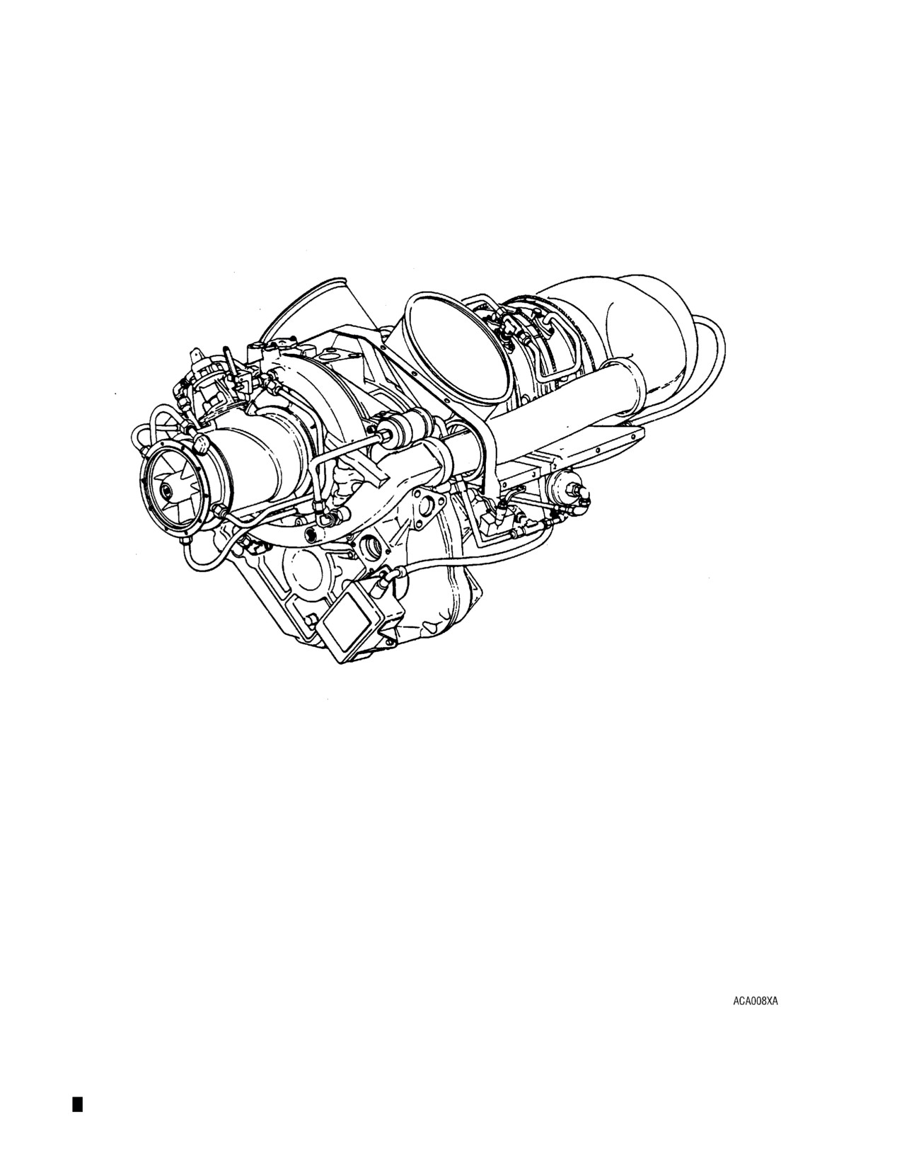
Engine Left Side View
FIG. 1
WARNINGS
IMPORTANT SAFETY NOTICE
IT IS YOUR RESPONSIBILITY to be completely familiar with the warnings and cautions de-
scribed in this manual. These warnings and cautions advise of specific operating and servicing
methods that, if not observed, can cause a serious engine malfunction or cause the engine to
lose power in flight which can result in loss of life, injury, or damage to equipment.
It is, however, important to understand that these warnings and cautions are not exhaustive.
Rolls-Royce could not possibly know, evaluate and advise the user of all conceivable ways in
which service might be done or of the possible hazardous consequences of each way. Conse-
quently, Rolls-Royce has not undertaken any such broad evaluation.
Proper methods of operation, service, and repair are important to the safe, reliable operation
of all equipment. The procedures recommended by Rolls-Royce and described in this manual
are effective methods for performing these operations. Some of these service operations re-
quire the use of tools specially designed for the purpose. The special tools should be used
when and as recommended. ROLLS-ROYCE STRONGLY RECOMMENDS THE PROCE-
DURES HEREIN SHOULD BE USED TO THE EXCLUSION OF OTHERS.
ANYONE WHO USES A SERVICE PROCEDURE OR TOOL WHICH IS NOT REC-
OMMENDED BY ROLLS-ROYCE MUST first be thoroughly satisfied that neither personal
safety, the safety of the eventual engine user, nor the equipment will be jeopardized by the
method selected. ANYONE USING PROCEDURES NOT RECOMMENDED BY ROLLS-
ROYCE ASSUMES THE RISK OF ANY CONSEQUENCE THAT MIGHT OCCUR.
WARNINGS, CAUTIONS, AND NOTES
The following definitions apply in this manual.
WARNING: A PROCEDURE, PRACTICE, CONDITION, STATEMENT, ETC, WHICH IF NOT STRICTLY
OBSERVED, COULD RESULT IN INJURY TO OR DEATH OF PERSONNEL.
CAUTION: A PROCEDURE, PRACTICE, CONDITION, STATEMENT, ETC, WHICH IF NOT STRICTLY
OBSERVED, COULD RESULT IN DAMAGE TO, OR DESTRUCTION OF, EQUIPMENT.
THIS COULD THEN POSSIBLY RESULT IN INJURY TO OR DEATH OF PERSONNEL.
NOTE: An essential procedure, condition, or statement, which must be highlighted.
LIST OF WARNINGS
1.
This manual contains the following warnings. IT IS YOUR RESPONSIBILITY to be familiar with them.
THE MAXIMUM OIL CONSUMPTION LIMIT IS 0.05 U.S. GALLONS PER HOUR (1 QUART IN FIVE HOURS).
OPERATION IN EXCESS OF THIS LIMIT IS NOT PERMITTED. EXCESSIVE OIL CONSUMPTION CAN BE
INDICATIVE OF A SERIOUS INTERNAL OIL LEAK. AN INTERNAL OIL LEAK CAN RESULT IN AN
UNDETECTED INTERNAL OIL FIRE, WHICH WILL RESULT IN A DISASTROUS TURBINE FAILURE.
TO PREVENT ENGINE FUEL SYSTEM CONTAMINATION WHICH COULD CAUSE ENGINE FLAMEOUT, AN
EXTERNAL LOW PRESSURE FUEL FILTER SHOULD BE USED ON ANY AIRCRAFT REFUELING FROM
REMOTE SITES (DRUMS ETC).
AT AMBIENT TEMPERATURES BELOW 40°F (4°C), SOME TYPE OF ANTI-ICE PROTECTION IS
REQUIRED, SUCH AS AN ANTI-ICE ADDITIVE OR A MEANS OF AIRFRAME FUEL ICE ELIMINATION.
ENGINE FLAMEOUT COULD RESULT FROM FAILURE TO USE ANTI-ICE PROTECTION. (REFER TO THE
AIRCRAFT MANUAL FOR THEIR RECOMMENDATIONS.)
ONLY DISCRETIONARY MIXING OF OILS WITHIN AN OIL SERIES IS PERMITTED WITHOUT A TIME
PENALTY. USE OF MIXED OILS FROM DIFFERENT SERIES IN AN ENGINE IS LIMITED TO FIVE HOURS
TOTAL RUNNING TIME DURING ONE OVERHAUL PERIOD. ADEQUATE MAINTENANCE RECORDS
MUST BE MAINTAINED TO ENSURE THAT THE FIVE HOUR LIMIT IS NOT EXCEEDED. FAILURE TO
COMPLY WITH OIL MIXING RESTRICTIONS CAN RESULT IN ENGINE FAILURE.
THE PRIMARY APPLICATION OF THIS TURBOSHAFT ENGINE IS TO POWER A HELICOPTER OR
ROTORCRAFT. A HEIGHT-VELOCITY DIAGRAM, AS REQUIRED BY REGULATION AND PREPARED BY
THE AIRFRAME MANUFACTURER, IS PUBLISHED IN THE AIRCRAFT FLIGHT MANUAL PERFORMANCE
SECTION FOR NORMAL CATAGORY ROTORCRAFT. THE OPERATOR MUST BECOME FAMILIAR WITH
THIS DIAGRAM TO DETERMINE WHAT AIRSPEEDS ARE REQUIRED TO SAFELY MAKE AN
AUTOROTATIONAL LANDING IN CASE OF POWER LOSS OR ENGINE FAILURE. THE
ALTITUDE-AIRSPEED COMBINATIONS WHERE A SAFE AUTOROTATIONAL LANDING MAY NOT BE
POSSIBLE ARE REPRESENTED BY THE SHADED OF CROSS-HATCHED AREA OF THE DIAGRAM.
SNOW OR ICE SLUGS CAN CAUSE THE ENGINE TO FLAME OUT. BE SURE AVAILABLE PREVENTIVE
EQUIPMENT IS INSTALLED AND IN PROPER WORKING ORDER WHEN FLYING IN CONDITIONS WHERE
SNOW OR ICE BUILDUP MIGHT OCCUR. CONSULT THE AIRCRAFT FLIGHT MANUAL FOR REQUIRED
EQUIPMENT AND PROCEDURES FOR FLIGHT IN FALLING/BLOWING SNOW.
CONSULT THE AIRCRAFT FLIGHT MANUAL FOR REQUIRED EQUIPMENT AND PROCEDURES FOR
FLIGHT IN FALLING/BLOWING SNOW.
SAND AND DUST WILL ERODE COMPRESSOR VANES AND CAUSE THEM TO FAIL.
SALT LADEN HUMIDITY AND CHEMICALS WILL CORRODE COMPRESSOR BLADES AND VANES AND
CAUSE THEM TO FAIL.
TO PREVENT SERIOUS ENGINE MALFUNCTION OR CRUCIAL LOSS OF POWER, DO NOT OPERATE THE
ENGINE IN EXCESS OF ANY SPECIFIED OPERATING LIMIT.
HOT STARTS OR AFTERFIRES AFTER SHUTDOWN CAN CAUSE TURBINE BLADE AND WHEEL DAMAGE
RESULTING IN ENGINE FAILURE.
TO PREVENT ENGINE FUEL STARVATION AND SUBSEQUENT FLAMEOUT, ANY AIRCRAFT REQUIRING
FUEL BOOST PUMP(S) SHOULD USE THESE PUMPS AT ALL TIMES DURING FLIGHT OR AS DIRECTED
IN THE AIRCRAFT FLIGHT MANUAL.
TO PREVENT CRUCIAL DELAY IN REGAINING POWER IF AN ENGINE FLAMEOUT IS ENCOUNTERED,
AIRCRAFT EQUIPPED WITH AN AUTO- RELIGHT SYSTEM SHOULD KEEP THAT SYSTEM ACTIVATED
AT ALL TIMES WHILE THE AIRCRAFT IS IN FLIGHT.
TO ENSURE ADEQUATE WARNING OF POSSIBLE EMERGENCY ENGINE OPERATING CONDITIONS,
VERIFY THAT THE ENGINE WARNING DEVICES (ENGINE-OUT HORN, FILTER BYPASS LIGHT AND CHIP
DETECTOR LIGHT) ARE OPERABLE BEFORE EACH FLIGHT.
LIST OF WARNINGS (cont)
OVERTEMPERATURE STARTS OR AFTERFIRES AFTER SHUTDOWN WILL CAUSE CRACKS IN THE
FIRST-STAGE WHEEL RIM. THESE CRACKS CAN EVENTUALLY CAUSE A SECTION OF THE WHEEL TO
BREAK OUT AND EXIT THE ENGINE WITH POTENTIALLY DISASTROUS RESULTS.
IDLE DWELL TIME PRIOR TO SHUTDOWN IS IMPORTANT TO PREVENT HARMFUL ACCUMULATION OF
CARBON IN THE ENGINE WHICH CAN RESULT IN ENGINE FAILURE.
DWELL TIME AT MINIMUM POWER BEFORE SHUTDOWN IS IMPORTANT TO PREVENT HARMFUL
ACCUMULATION OF CARBON IN THE ENGINE. CARBON BUILDUP CAN RESULT IN ENGINE FAILURE.
BE AWARE OF THE POTENTIAL FIRE HAZARD OF FUEL IN AN OPEN CONTAINER.
MANDATORY COMPLIANCE DATE FOR ROLLS-ROYCE 250-C18 CEB-A-161 WAS NOVEMBER 1, 1989.
IT IS NOT ALLOWED TO INSTALL A TURBINE WHEEL WITH ACCEPTABLE WHEEL RIM CRACKS IN ANY
ENGINE/TURBINE DURING OVERHAUL. ACCEPTABLY CRACKED TURBINE WHEELS MAY BE
REINSTALLED ONLY DURING A TIME CONTINUED ENGINE/TURBINE REPAIR.
DO NOT EXCEED SPECIFIED AIRCRAFT OR ENGINE LIMITATIONS DURING PERFORMANCE OF THIS
(TREND) CHECK.
DO NOT TURN OFF SYSTEMS OR COMPONENTS REQUIRED FOR SAFE FLIGHT. IF ANTI-ICE IS
FREQUENTLY REQUIRED FOR SAFE FLIGHT, IT SHOULD BE OPERATED DURING EACH TREND CHECK.
PROPER TIGHTENING OF ENGINE TUBING CONNECTIONS IS CRITICAL TO FLIGHT SAFETY.
CORRECT TORQUE VALUES MUST BE USED AT ALL TIMES. EXCESSIVE TORQUE ON PNEUMATIC
SENSING SYSTEM CONNECTIONS RESULTS IN CRACKING OF THE FLARE OR ADJACENT TUBE AREA
IN CONTACT WITH THE FERRULE. THIS PRODUCES AN AIR LEAK WHICH CAN CAUSE FLAMEOUT,
POWER LOSS, OR OVERSPEED.
TUBING B-NUTS USED IN INSTALLATIONS EXPOSED TO A HIGH DEGREE OF VIBRATION AND
PRESSURE SURGES ARE SUBJECT TO TORQUE RELAXATION WHEN IMPROPERLY TIGHTENED.
USE ACCEPTABLE TECHNIQUES AND PRACTICES TO PREVENT TORQUE PAINT OR TORQUE PAINT
REMOVER FROM CONTACTING RUBBER OR PLASTIC MATERIALS OR ENTERING EXPOSED AREAS.
EVEN THOUGH ROLLS-ROYCE HAS APPROVED THE CONSUMABLE MATERIALS IN THIS MANUAL FOR
USE WITH ROLLS-ROYCE ENGINES, ROLLS-ROYCE ASSUMES NO LIABILITY FOR INJURY TO
PERSONNEL OR DAMAGE TO THE ENVIRONMENT BY THEIR USE.
MINERAL SPIRITS IS TOXIC. PROVIDE ADEQUATE VENTILATION FOR PERSONNEL USING IT.
FAILURE TO PROPERLY INSTALL, ALIGN AND TORQUE FUEL, OIL, AND AIR FITTINGS AND TUBES
COULD RESULT IN AN ENGINE FAILURE.
CORROSION OR EROSION WILL CAUSE DAMAGE TO COMPRESSOR BLADES AND VANES WHICH CAN
RESULT IN ENGINE FAILURE.
WATER OR CONTAMINATION IN THE FUEL CAN CAUSE FLAMEOUT OR POWER LOSS.
AIR LEAKS IN THE FUEL SYSTEM PNEUMATIC SENSING SYSTEM CAN CAUSE FLAMEOUTS, POWER
LOSS OR OVERSPEED.
PERFORM A VACUUM CHECK OF THE FUEL SYSTEM LINES AND COMPONENTS ANYTIME A FUEL
SYSTEM COMPONENT IS REMOVED OR REPLACED TO ENSURE NO ENGINE OR AIRFRAME FUEL
SYSTEM LEAKS ARE PRESENT.
THE FUEL/AIR DISCHARGE DURING PURGING IS IRRITATING AND HIGHLY FLAMMABLE. MECHANICS
MUST TAKE SUITABLE MEASURES TO PROTECT THEIR EYES AND PREVENT FIRE.
ENSURE THAT THE AIRCRAFT IS ADEQUATELY GROUNDED. SEE AIRCRAFT MANUFACTURER’S
INSTRUCTIONS FOR PROPER GROUNDING PROCEDURES.
FAILURE TO PROPERLY REMOVE OR INSTALL Pc AIR TUBES MAY DAMAGE TUBES, FITTINGS, AND/OR
THE FILTER ASSEMBLY WHICH CAN RESULT IN SUDDEN UNINTENDED ENGINE POWER LOSS.
LIST OF WARNINGS (cont)
SODIUM HYDROXIDE CAN CAUSE SEVERE BURNS. DO NOT GET IN EYES, ON SKIN, OR ON CLOTHING.
IN THE EVENT OF CONTACT WITH SODIUM HYDROXIDE, IMMEDIATELY FLOOD EXPOSED SKIN OR
CLOTHING WITH WATER. FOR EYES, FLUSH HEAVILY WITH WATER AND OBTAIN IMMEDIATE MEDICAL
ATTENTION.
POTASSIUM PERMAGANATE CAN BE VERY DANGEROUS IF IMPROPERLY HANDLED. CONTACT WITH
ORGANIC MATERIALS (OIL, GREASE) CAN CAUSE FIRE.
SULPHURIC ACID CAUSES SEVERE BURNS. DO NOT GET IN EYES, ON SKIN OR ON CLOTHING. DO
NOT ADD WATER TO ACID WHILE IN A CONTAINER BECAUSE OF VIOLENT REACTION. IN THE EVENT
OF CONTACT WITH SULPHURIC ACID, IMMEDIATELY FLOOD EXPOSED SKIN OR CLOTHING WITH
WATER. FOR EYES, FLUSH HEAVILY WITH WATER AND OBTAIN IMMEDIATE MEDICAL ATTENTION.
DURING THE ACCELERATION CHECK, THE AIRCRAFT MAY REACT OR BECOME LIGHT ON ITS SKIDS.
DO NOT SNAP TWIST GRIP TO FULL THROTTLE POSITION.
DO NOT EXCEED TORQUE, TEMPERATURE, OR N1 SPEED LIMITS DURING THE ACCELERATION
CHECK.
THE HELICOPTER MAY LIFT OFF DURING THIS CHECK IF IT IS NOT SUFFICIENTLY LOADED.
AVOID FUEL ACCUMULATION IN THE ENGINE COMPARTMENT BY PROVIDING A SUITABLE CONTAINER
TO COLLECT FUEL DISCHARGED FROM THE TYGON TUBE ATTACHED TO THE AF PRESSURE PORT.
MAINTAIN THE COMPLETE OIL SYSTEM IN ACCORDANCE WITH ENGINE AND AIRCRAFT
INSTRUCTIONS. FAILURE TO MAINTAIN THE OIL SYSTEM CAN RESULT IN SUDDEN ENGINE
STOPPAGE.
OPERATORS MUST MAINTAIN THE ENGINE MAGNETIC DRAIN PLUGS AND INDICATING SYSTEM IN
OPERATING ORDER AND COMPLY WITH AIRCRAFT FLIGHT MANUAL AND ENGINE OPERATION AND
MAINTENANCE MANUAL INSTRUCTIONS WHEN AN INDICATION IS RECEIVED. NEVER ALLOW AN
ACCEPTABLE SPECTROGRAPHIC OIL ANALYSIS PROGRAM (SOAP) READING TO OVERRIDE
MAGNETIC DRAIN PLUG INDICATIONS.
IF A MAGNETIC PLUG WARNING LIGHT COMES ON DURING FLIGHT, LAND AND INSPECT THE
MAGNETIC PLUGS AS SOON AS POSSIBLE. THIS LIGHT IS AN INDICATION OF CONDITIONS WHICH
COULD CAUSE ENGINE FAILURE. WHEN FLYING A MULTI-ENGINE AIRCRAFT, REDUCE THE
AFFECTED ENGINE OUTPUT POWER TO THE MINIMUM REQUIRED FORFLIGHT AND LAND AS SOON
AS PRACTICABLE. IF THE LIGHT IS ACCOMPANIED BY ABNORMAL NOISES, OIL PRESSURE OR
TEMPERATURE, AND SINGLE-ENGINE FLIGHT CAN BE MAINTAINED, SHUT DOWN AFFECTED ENGINE
AND LAND AS SOON AS PRACTICABLE. IF SINGLE-ENGINE FLIGHT IS NOT POSSIBLE, REDUCE
POWER OF AFFECTED ENGINE TO THE MINIMUM AND LAND AS SOON AS POSSIBLE. AFTER
LANDING, INSPECT THE MAGNETIC PLUGS ON THE AFFECTED ENGINE FOR METAL CONTAMINATION
PRIOR TO FURTHER ENGINE OPERATION.
FAILURE TO COMPLY WITH OIL MIXING RESRICTIONS CAN RESULT IN ENGINE FAILURE.
MAKE SURE THAT THE IGNITION SWITCH IS OFF BEFORE REMOVING THE SPARK IGNITER OR SPARK
IGNITER LEAD ASSEMBLY AS DANGEROUSLY HIGH VOLTAGES MAY BE PRESENT. ALLOW FIVE
MINUTES AFTER OPERATION FOR ELECTRICAL DISSIPATION BEFORE DISASSEMBLY.
TO PREVENT ELECTRICAL SHOCK DURING INSTALLATION OF THE SPARK IGNITER AND THE LEAD,
ALLOW FIVE MINUTES FOR ELECTRICAL DISSIPATION FOLLOWING IGNITION OPERATION OR TEST.
FAILURE TO PROPERLY SHIM THE COMPRESSOR AT INSTALLATION CAN CAUSE THE SPUR ADAPTER
GEARSHAFT TO FAIL RESULTING IN SUDDEN ENGINE STOPPAGE.
AN ENGINE WHICH HAS BEEN OPERATED ON LEADED FUEL HAS A PALE YELLOW POWDER RESIDUE
ON THE EXHAUST PASSAGES. HANDLING LEAD RESIDUE COATED PARTS BY PERSONS WITH OPEN
CUTS OR SCRATCHES ON THEIR HANDS CAN BE EXTREAMLY DANGEROUS. ALWAYS WEAR GLOVES
WHEN HANDLING RESIDUE COATED PARTS.
LIST OF WARNINGS (cont)
AIR LEAKAGE ACROSS THE U-RING SEAL WILL RESULT IN PRESSURIZATION OF THE NO. 8 SUMP.
PRESSURIZATION OF THE NO. 8 SUMP WILL CAUSE A FLOW REVERSAL ACROSS THE NO. 8
LABYRINTH SEAL. THIS LEAKAGE CAN RESULT IN AN ENGINE OIL FIRE AND SUBSEQUENT TURBINE
WHEEL RIM FAILURE CAUSING A SECTION OF THE WHEEL RIM TO EXIT THE ENGINE WITH
POTENTIALLY SERIOUS RESULTS.
OIL CONTACTING THE HOT TURBINE WHEEL CAN CAUSE EXCESSIVE TEMPERATURE AND
ULTIMATELY CAUSE WHEEL FAILURE.
DO NOT BURN DISCARDED TEFLON SEALS. TOXIC GASES WILL BE PRODUCED.
PERCHLORETHYLENE IS TOXIC AND MUST BE USED WITH EXTREME CAUTION. MAKE SURE
ADEQUATE VENTILATION IS PROVIDED. REPEATED OR PROLONGED CONTACT WITH THE SKIN
SHOULD BE AVOIDED.
LEAKAGE ACROSS THE NO. 8 BEARING LABYRINTH AIR SEAL (DURING PRESSURE TEST),
EVIDENCED BY VIGOROUS FORMATION OF BUBBLES, WILL PRESSURIZE THE NO. 8 BEARING SUMP.
THE PRESSURIZED SUMP FORCES OIL THROUGH THE SEAL ONTO THE WEB OF THE 1st-STAGE
WHEEL. THIS LEAKAGE MAY RESULT IN ENGINE FIRE AND TURBINE WHEEL (RIM) FAILURE. WHEEL
FAILURE CAN EVENTUALLY CAUSE A SECTION OF THE RIM TO BREAK OUT AND EXIT THE ENGINE
WITH POTENTIALLY DISASTROUS RESULTS.
TORQUE PAINT (SLIPPAGE MARKS) SHALL BE APPLIED TO ALL RIGID TUBE B-NUTS IN ACCORDANCE
WITH RIGID TUBE INSTALLATION PROCEDURES IN SECTION III. TORQUE PAINT SHALL BE REMOVED
AND REAPPLIED ANYTIME THE B-NUT IS RETIGHTENED.
ENGINE DESCRIPTION
1.
General
A. Engine description includes a discussion of each major component and each major system of the
engine.
B. Numerical values in this manual are given in terms standard to existing practices in the United
States.
2.
Components
The major engine components are compressor, combustion section, turbine, and power and accessories
gearbox.
A.
Compressor
The compressor assembly consists of a compressor front support, case assembly, rotor wheels
with blades, centrifugal impeller, front diffuser assembly, rear diffuser assembly, and diffuser scroll.
Air enters the engine through the compressor inlet and is compressed by six axial compressor
stages and one centrifugal stage. The compressed air is discharged through the scroll type diffuser
into two external ducts which convey the air to the combustion section. (Ref. FIG. 1)
B.
Combustion Section
The combustion section consists of the outer combustion case and the combustion liner. A spark
igniter and a fuel nozzle are mounted in the aft end of the outer combustion case. Air enters the
single combustion liner at the aft end, through holes in the liner dome and skin. The air is mixed
with fuel sprayed from the fuel nozzle and combustion takes place. Combustion gasses move
forward out of the combustion liner to the 1st-stage gas producer turbine nozzle.
C.
Turbine
The turbine consists of a gas producer turbine support, a power turbine support, a turbine and
exhaust collector support, a gas producer turbine rotor and a power turbine rotor. The turbine is
mounted between the combustion section and the power and accessories gearbox. The two-stage
gas producer turbine drives the compressor and accessories gear train. The two-stage power
turbine furnishes the output power of the engine. The expanded gas discharges in an upward
direction through the twin ducts of the turbine and exhaust collector support.
D.
Power And Accessories Gearbox
The main power and accessories drive gear trains are enclosed in a single gear case. The gear
case serves as the structural support of the engine. All engine components including the engine
mounted accessories are attached to the case. A two-stage helical and spur gear set is used to
reduce rotational speed from 35,000 rpm at the power turbine to 6000 rpm at the output drive
spline. Accessories driven by the power turbine gear train are the power turbine
tachometer-generator and the power turbine governor. The gas producer gear train drives the
compressor, fuel pump, gas producer tachometer-generator, and gas producer fuel control. The
starter drive and a spare drive are in this gear train.
3.
Systems
The major systems of the engine are fuel, lubrication, electrical, anti-icing air, and compressor bleed air.
A. Fuel System
There are four basic fuel control system configurations which can be encountered. These
configurations, identified as A, B, C and D, include the following major components:
Page 1
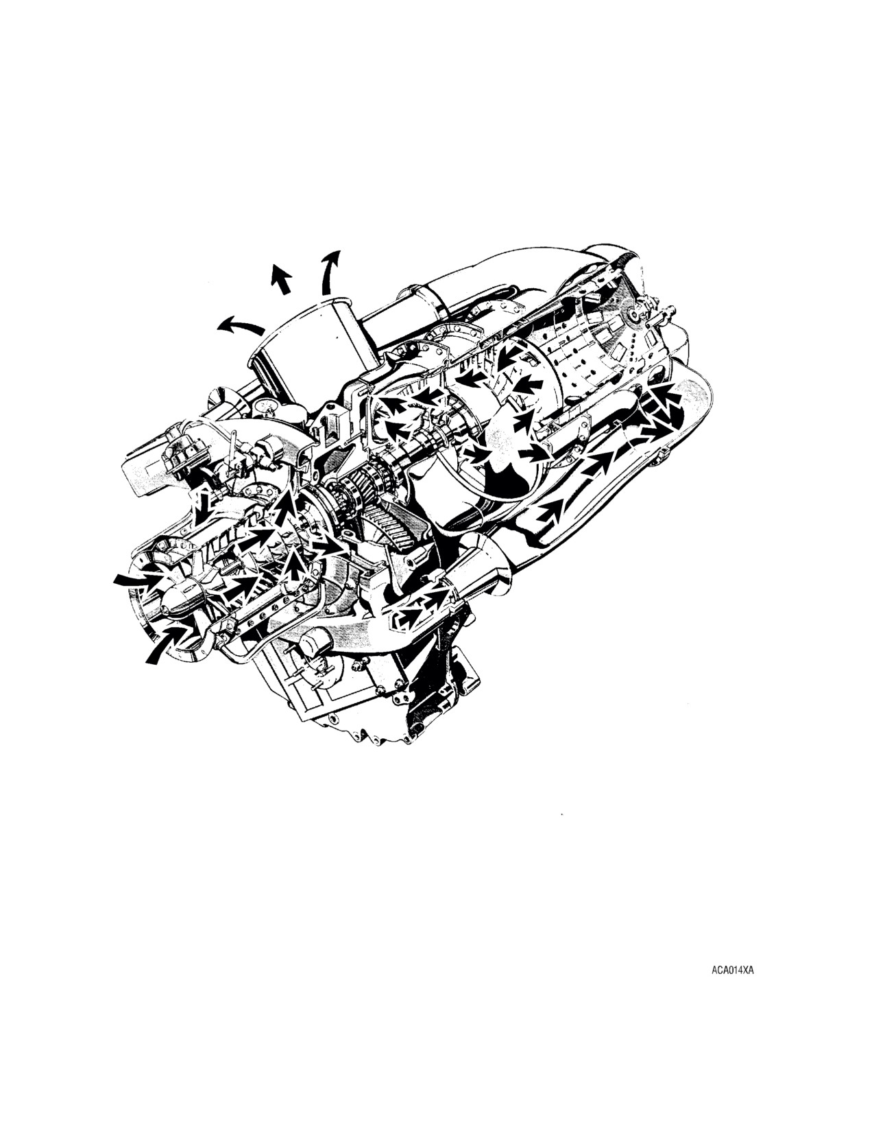
Engine Air Flow
FIG. 1
Page 2
(1) Configuration A. (Ref. FIG. 2) This is the non start-derichment configuration which includes a
gas producer fuel control (P/N 6856290, 6858481, or 6870545); a power turbine governor (P/N
6856291, 6858482, or 6870546); a fuel pump and filter assembly (single or double element); a
Pc filter; an accumulator; a double check valve (P/N 6873599); and a fuel spray nozzle.
(2) Configuration B. (Ref. FIG. 3) This is the start-derichment configuration which has the same
major components as configuration A except for changes in the control and governor. This
configuration includes start-derichment fuel control (P/N 6870587, 6870887, 6871104, or
6875063) and compound governor (P/N 6870096 or 6873450).
(3) Configuration C. (Ref. FIG. 3) This is also a start-derichment configuration which has the
same major components as configuration B except for changes in the control and governor.
The system includes a step-orifice fuel control (P/N 6874951, 6871108, or 6871119) which has
detuned springs and lever bushings as does the governor (P/N 6874952); and a
diaphragm-type double check valve (P/N 6873599).
(4) Configuration D. (Ref. FIG. 3) This latest configuration system includes many changes to the
Fuel Control and Governor. The Fuel Control now incorporates a wider range start derichment
adjustment and a start/acceleration schedule adjuster. Screens have been added to the Px &
Py orifices and the Py fittings to protect against contamination. Anti-corrosion treatments are
added to internal parts to reduce corrosion and extend service life. The governor incorporates
a screened Pg orifice and screened fittings in the Pr, Pg, and Py ports. The drive shaft and
flyweight assembly has also been redesigned for external service life.
B.
System Control.
(1) The system controls engine power output by controlling the gas producer speed. Gas
producer speed levels are established by the action of the power turbine fuel governor which
senses power turbine speed. The power turbine (load) speed is selected by the operator and
the power required to maintain this speed is automatically maintained by power turbine
governor reset action on metered fuel flow.
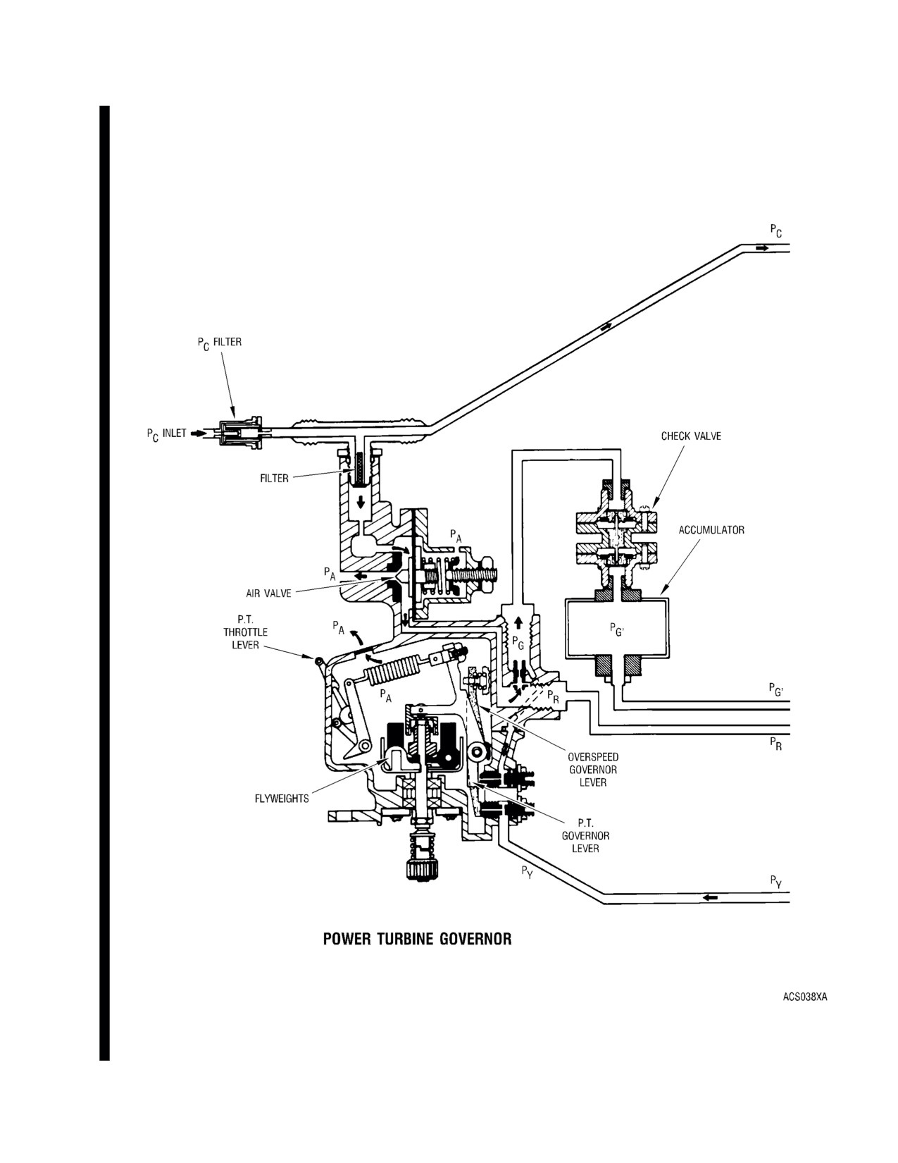
(2) The power turbine governor lever schedules the power turbine governor requirements. The
power turbine governor, in turn, schedules the gas producer speed to a changed power output
to maintain output shaft speed.
(3) Fuel flow for engine control is established as a function of compressor discharge pressure
(Pc), engine speed (gas producer--N1 and/or power turbine--N2), and gas producer lever
angle. Fuel flow is a function of Pc as sensed in the fuel control. Variations of the fuel flow
schedules are obtained by modulating the Pc or Px and Py pressures in the control through the
action of a bleed-down circuit actuated by the governors. (Ref. FIG. 4, 5, 6, or 7)
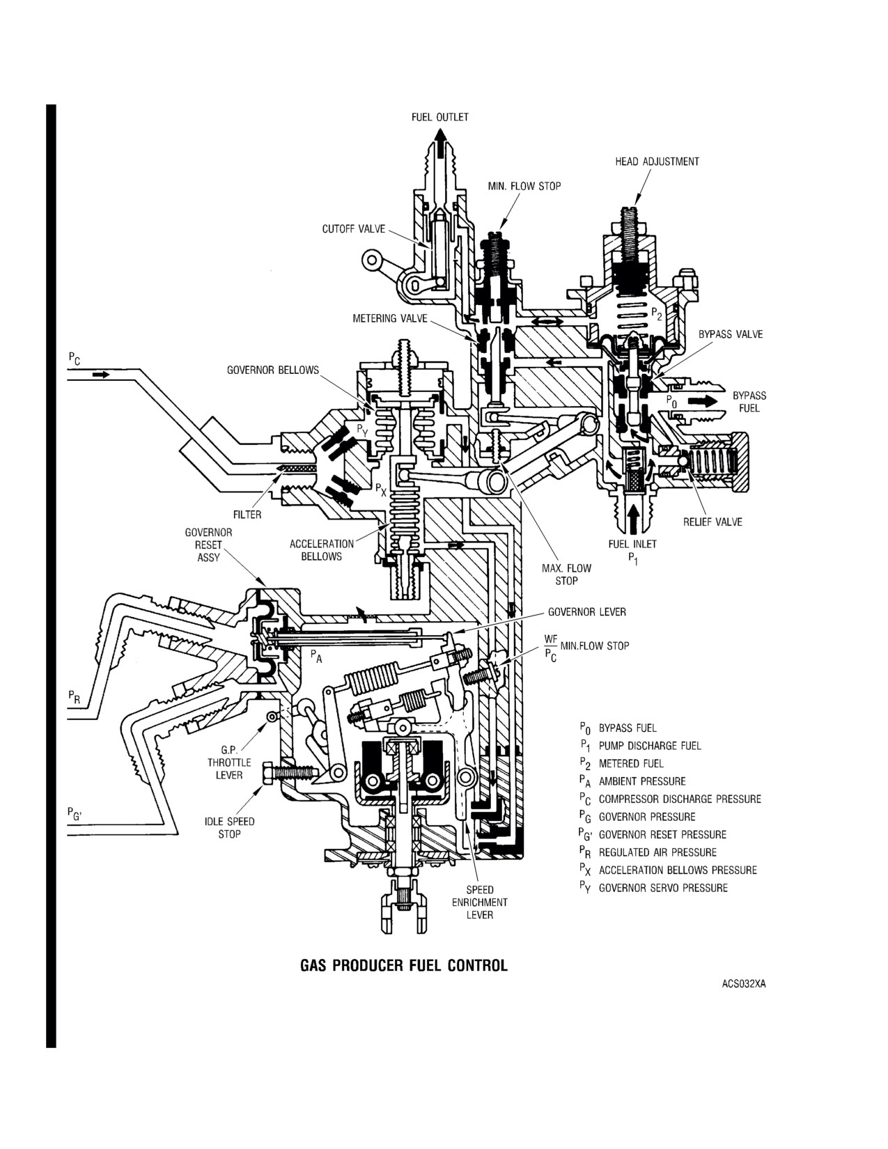
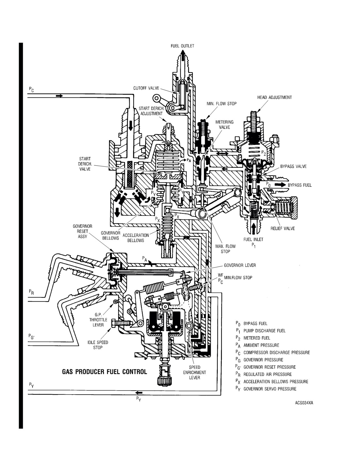
C.
Gas Producer Fuel Control.
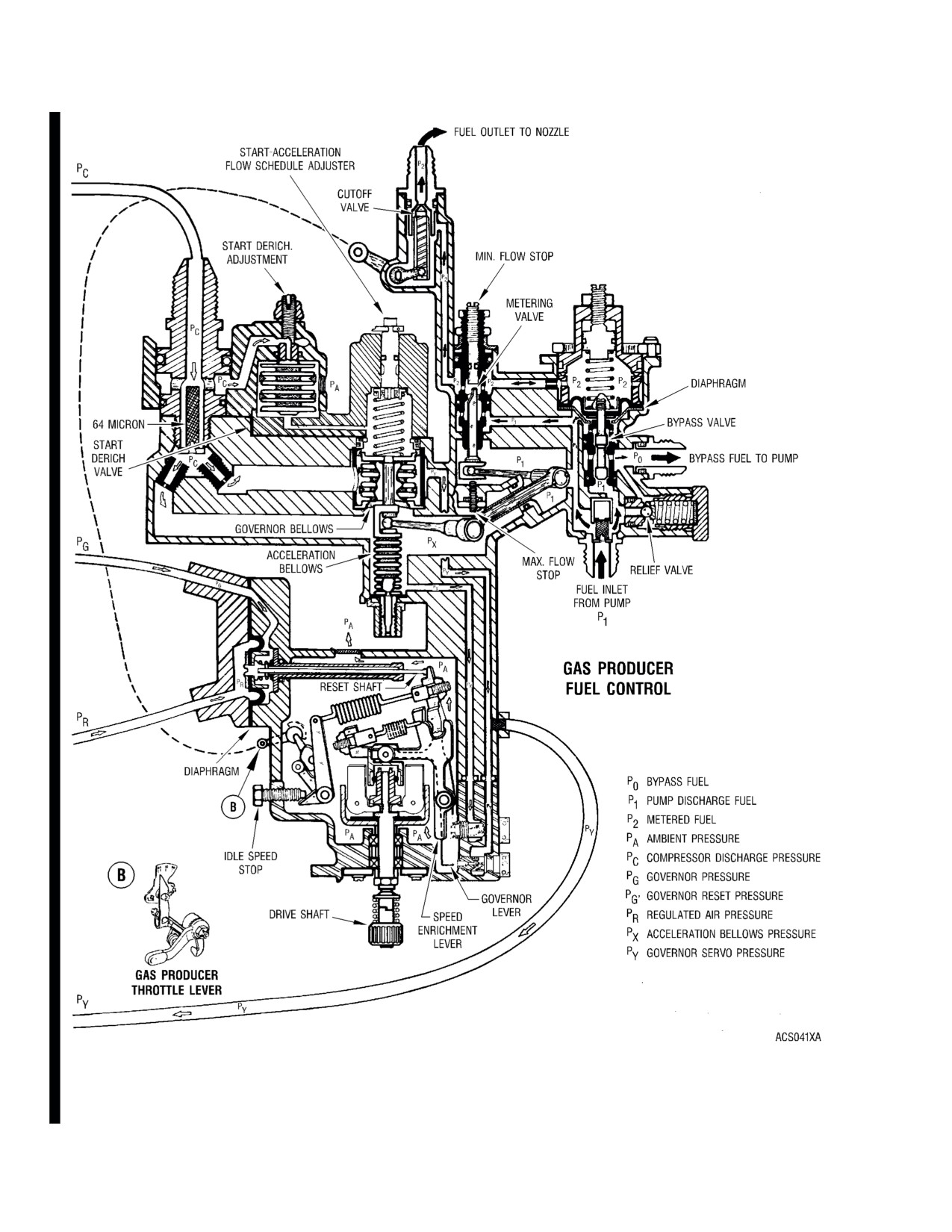
(1) The gas producer fuel control has a bypass valve, metering valve, acceleration bellows,
governing and enrichment bellows, manually operated cutoff valve, maximum pressure relief
valve, a torque tube seal and lever assembly and in some configurations a start derichment
valve. A maximum pressure relief valve is incorporated to protect the system from excessive
fuel pressure.
(2) Fuel enters the control from the engine fuel pump and filter assembly and is conveyed to the
metering valve. The bypass valve maintains a constant pressure differential across the
metering valve and bypasses excess fuel back to the fuel pump and filter assembly through an
external line connecting the pump bypass inlet to the bypass outlet port of the gas producer
fuel control.
(3) The metering valve is operated by lever action through movement of the governor and
acceleration bellows. Metering valve area is a function of valve travel. Before light-off and
acceleration the metering valve is established at a predetermined open position by the
acceleration bellows (aneroid) under influence of ambient pressure (Pc at zero rpm).
Page 3
(4)
On fuel controls with a start derichment valve, the start derichment valve is open during
light-off and acceleration to a set Pc. The open derichment valve vents Py pressure to
atmosphere. Venting Py allows the governor bellows to move the metering valve against the
min flow stop. At min flow the metering valve provides the required lean fuel schedule after
light-off. As compressor rpm increases, the derichment valve is closed by Pc acting on the
derichment bellows. When the derichment valve is closed, control of the metering valve is
returned to the normal operating schedule.
(5)
During acceleration the Px and Py pressures are equal to the modified compressor discharge
pressure (Pc) up to the point where the speed enrichment orifice is opened by flyweight action.
Opening the speed enrichment orifice bleeds Px pressure while Py remains at a value equal to
Pc. Under the influence of the Py minus Px pressure drop across the governor bellows, the
metering valve moves toward the max flow stop where it provides increased fuel flow.
(6)
Gas producer speed is controlled by the gas producer fuel control governor. A set of
flyweights operate the governor lever which controls the governor bellows (Py) bleed at the
governing orifice. Flyweight operation of the governor lever is opposed by a variable spring
load. The spring force is established by the throttle lever acting on a spring scheduling cam.
Opening the governing orifice bleeds Py pressure and allows Px pressure to control the
governor bellows. The Px influence on the bellows moves the metering valve toward min flow
and at a position where metered flow is at steady state requirements.
(7)
The governor reset assembly in the gas producer fuel control limits or governs power turbine
speed. Control of the reset assembly is derived from the power turbine governor. The power
turbine governor also provides quick responding overspeed protection by bleeding governor
servo (Py) pressure from the gas producer fuel control.
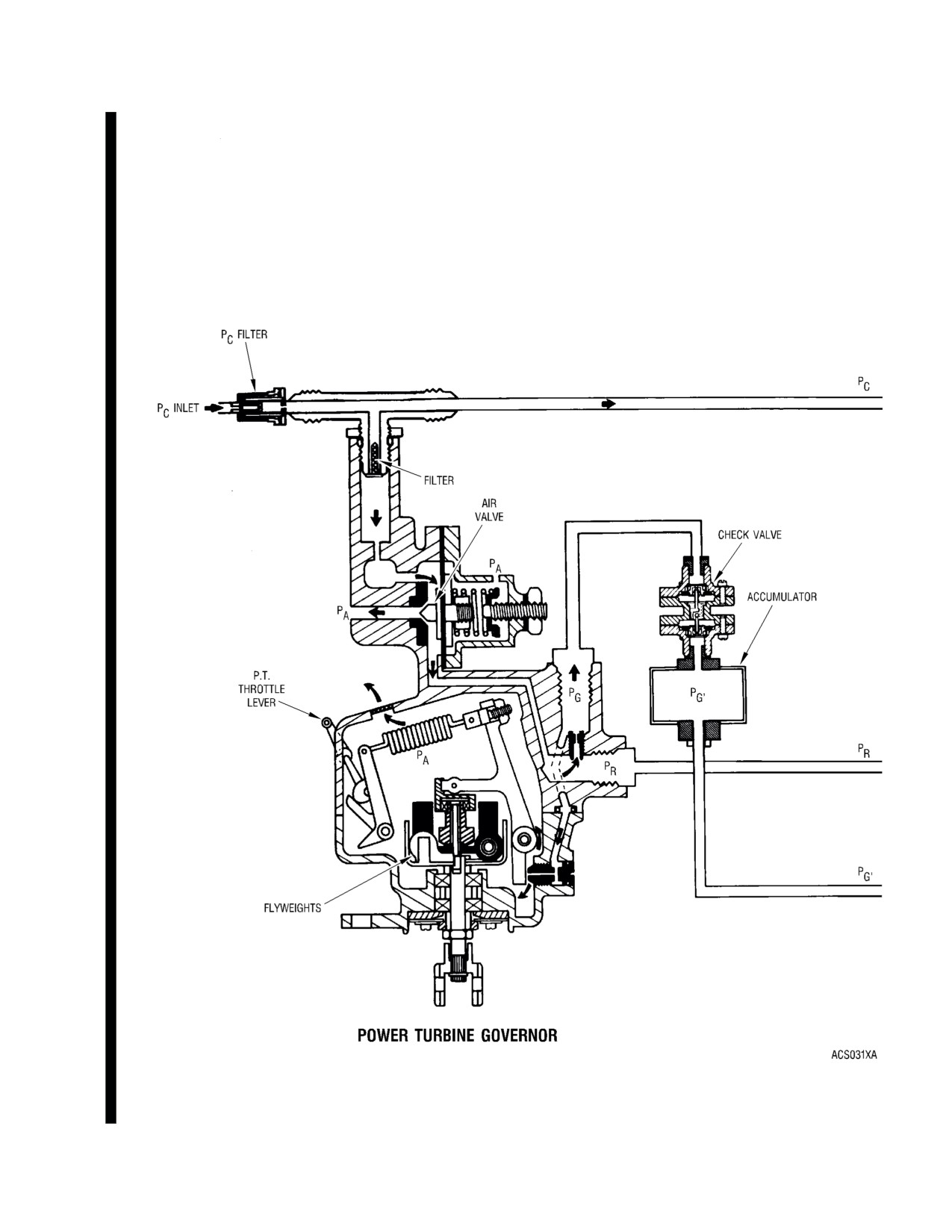
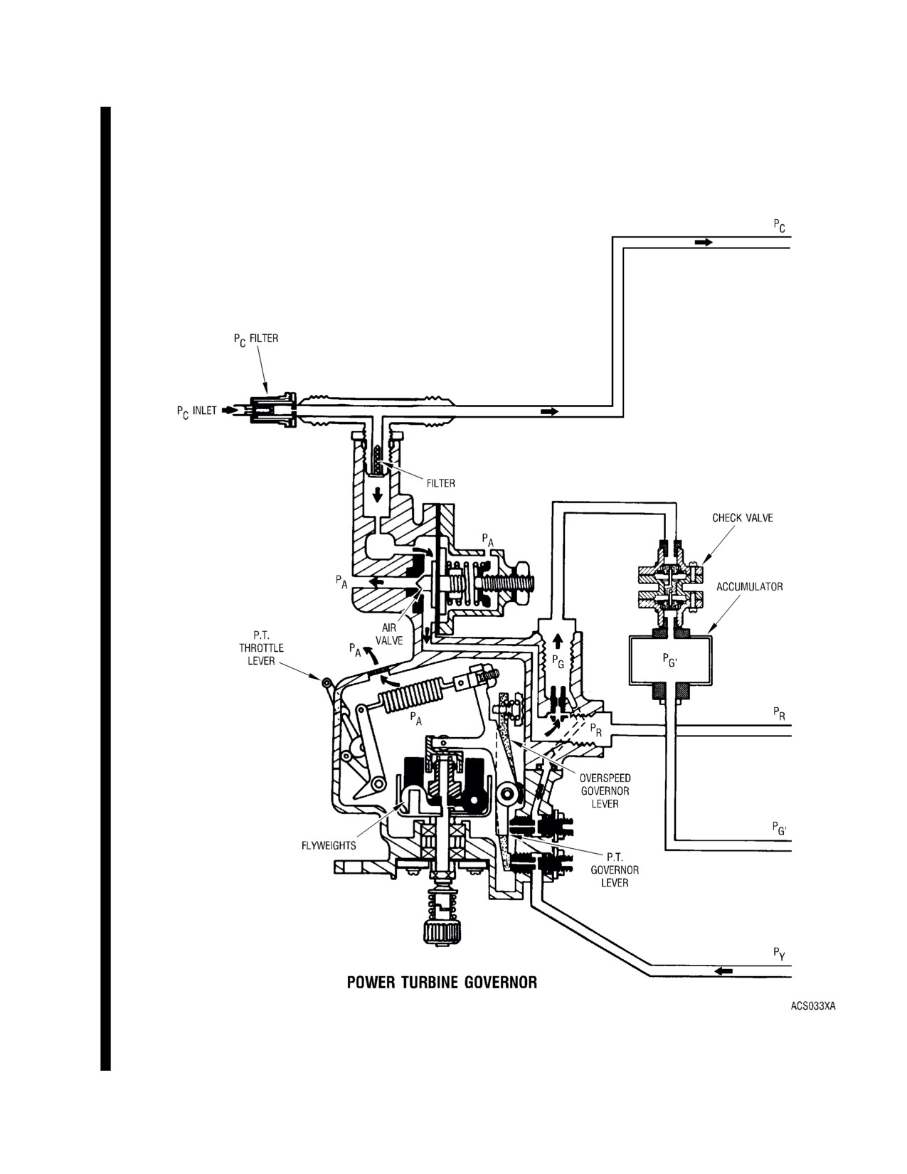
D.
Power Turbine Fuel Governor.
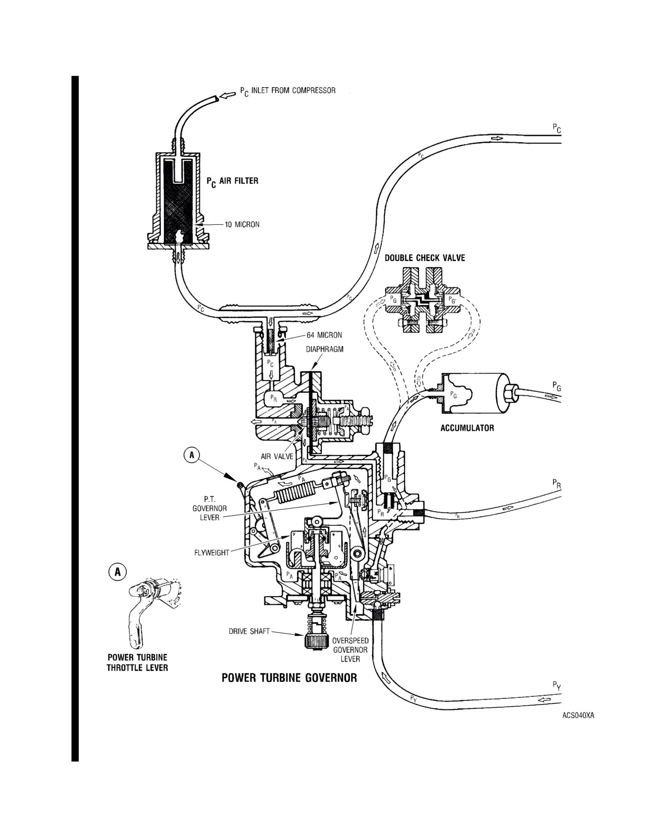
(1) The power turbine speed is scheduled by the power turbine governor lever and the power
turbine speed scheduling cam. The cam sets a governor spring load which opposes a
speed-weight output. As the desired speed is approached the speed weights, operating
against the governor spring, move a link to open the power turbine governor orifice. On
compound governor configurations the speed weights also open the overspeed bleed (Py)
orifice; but, at a higher speed than where the regular governor orifice (Pg) is opened.
(2) The governor orifice is downstream of a bleed supplied by a regulated air pressure, Pr.
Opening the orifice results in a reduced pressure downstream of the bleed (Pg) as an inverse
function of increasing speed. Regulated pressure (Pr) and governing pressure (Pg) are applied
to opposite sides of a diaphragm in the governor reset section of the gas producer fuel control.
The force generated by Pr - Pg across the diaphragm acts on the gas producer power output
link through the governor reset rod and supplements the weight force in the gas producer fuel
governor to reset (reduce) the gas producer speed. Gas producer speed cannot exceed the
gas producer fuel governor setting. The Pr - Pg diaphragm is pre-loaded for establishing the
active Pr minus Pg range. Pr pressure is supplied from engine Pc pressure by an air regulator
valve.
(3) On the compound governor configuration the overspeed orifice bleeds Py pressure from the
governing system of the gas producer fuel control. Bleeding Py pressure at the power turbine
governor gives the fuel control system a rapid response to overspeed conditions.
E.
Fuel Pump and Filter Assembly. The fuel pump and filter assembly may be either a dual or a single
element unit.
(1) Dual Element Fuel Pump. (Ref. FIG. 8)
Page 4
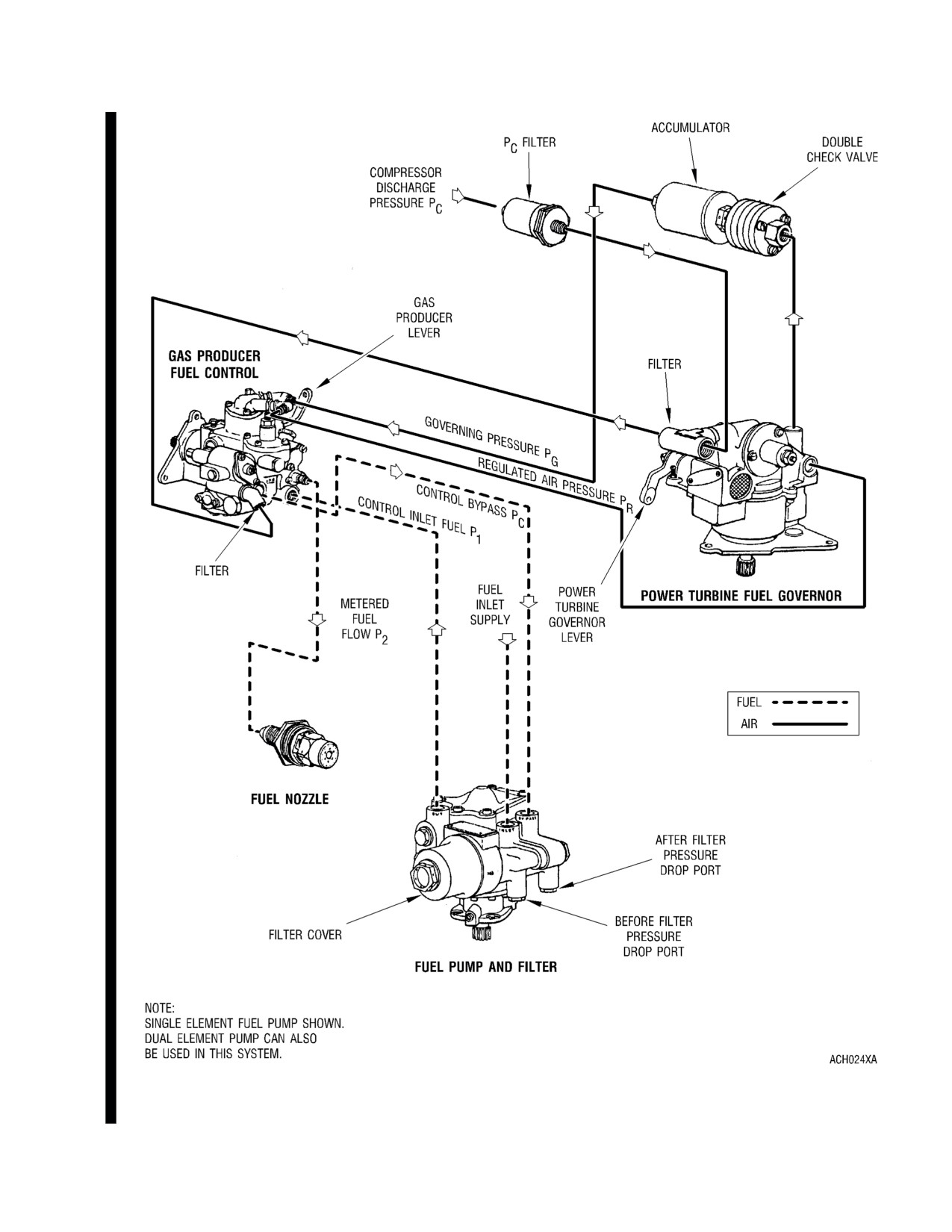
Engine Fuel Control System (Configuration A)
FIG. 2
Page 5
May 15/00
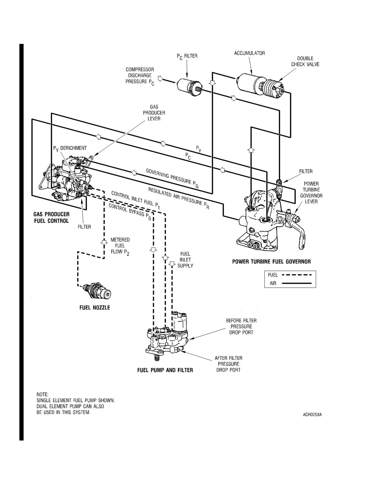
Engine Fuel Control System (Configurations B, C, and D)
FIG. 3
Page 6
May 15/00
Fuel Control System Schematic (Configuration A) (Sheet 1 of 2)
FIG. 4
Page 7
Mar 1/01
Fuel Control System Schematic (Configuration A) (Sheet 2 of 2)
FIG. 4
Page 8
Mar 1/01
Fuel Control System Schematic (Configuration B) (Sheet 1 of 2)
FIG. 5
Page 9
Mar 1/01
Fuel Control System Schematic (Configuration B) (Sheet 2 of 2)
FIG. 5
Page 10
Mar 1/01
Fuel Control System Schematic (Configuration C) (Sheet 1 of 2)
FIG. 6
Page 11
Mar 1/01

Fuel Control System Schematic (Configuration C) (Sheet 2 of 2)
FIG. 6
Page 12
Mar 1/01
Fuel Control System Schematic (Configuration D) (Sheet 1 of 2)
FIG. 7
Page 13
Mar 1/01
Fuel Control System Schematic (Configuration D) (Sheet 2 of 2)
FIG. 7
Page 14
Mar 1/01
Fuel Pump Assembly - Dual Element
FIG. 8
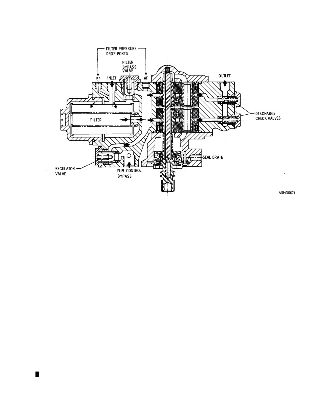
(2) The fuel pump and filter assembly incorporates two gear-type pumping elements arranged in
tandem and driven by a common drive shaft. Fuel enters the engine fuel system at the inlet
port of the pump and passes through a low pressure filter before entering the gear elements.
The gear elements are arranged in parallel and each pumping element has sufficient capacity
to permit takeoff power operation in the event of failure of the other pumping element. Two
discharge check valves are provided in the assembly to prevent reverse flow in event of failure
of one gear pumping element. A bypass valve in the pump assembly allows fuel to bypass the
filter element if it becomes clogged.
(3) The bypass return flow from the fuel control is passed back to the inlet of the gear elements
through a pressure regulating valve which maintains the bypass flow pressure above inlet
pressure. By means of passages leading to auxiliary filling ports on the periphery of the gear
elements, a portion of the bypass flow is used to fill the gear teeth when vapor-liquid
conditions exist at the inlet to the gear elements.
(4) The 5 micron nominal/15 micron absolute replaceable filter is located inside the fuel pump
assembly upstream of the gear elements. It is retained by a threaded cover (distinguished by
a hex) which can be found on the lower side of the pump assembly. To minimize the spilling of
fuel, fuel may be drained through the “Before Filter” pressure drop port (BF) before removing
the filter cover. A container should be used to catch undrained fuel when the filter cover is
removed.
(5) Single Element Fuel Pump. (Ref. FIG. 9 and 10)
Page 15
(6) The fuel pump and filter assembly incorporates a single gear-type pumping element, a low
pressure barrier filter, a filter bypass valve, and a bypass pressure regulating valve. Fuel
enters the engine fuel system at the inlet port of the pump and passes through the low
pressure filter before entering the gear element. The filter bypass valve allows fuel to bypass
the filter element if it becomes clogged.
(7) The bypass return flow from the fuel control is passed back to the inlet of the gear element
through a pressure regulating valve which maintains the bypass flow pressure above inlet
pressure. By means of passages leading to auxiliary filling ports on the periphery of the gear
element, a portion of the bypass flow is used to fill the gear teeth when vapor-liquid conditions
exist at the inlet to the gear element.
(8) The 5 micron nominal/15 micron absolute replaceable filter is located inside the fuel pump
assembly upstream of the gear element. It is retained by a cast cover attached to the pump
housing by two socket head cap screws. The cover is located on the aft side of the pump. To
minimize fuel spillage during filter replacement, fuel may be drained through the lower of the
two drain ports located on the aft face of the filter cover. Pressure taps are provided before
and after (labeled BF and AF) the filter element to permit measurement of filter pressure drop
if desired.
4.
Fuel Nozzle
The fuel nozzle is a single-entry dual-orifice type unit which contains an integral valve for dividing
primary and secondary flow. This same valve acts as a fuel shutoff valve when the fuel manifold
pressure falls below a predetermined pressure, thus keeping fuel out of the combustion chamber at
shutdown.
5.
Lubrication System (Ref. FIG. 11 and 12)
CAUTION: THE TWO OIL SCREENS USED IN THIS ENGINE ARE NOT INTERCHANGEABLE.
THE OD DIAMETER TO THE POWER TURBINE SUPPORT SCREEN IS 0.325 IN. (8.26
MM) AND THE POWER AND ACCESSORY GEARBOX HOUSING SCREEN IS 0.360
IN. (9.14 MM).
The lubrication system is a dry sump type with an external reservoir and heat exchanger. A gear type
pressure and scavenge pump assembly is mounted within the power and accessories gearbox. The oil
filter, filter bypass valve, and pressure regulating valve are in a unit which is located in the upper right
hand side of the power and accessories gearbox housing and are accessible from the top of the engine.
A check valve is located between the housing and the filter unit. Indicating type magnetic chip detectors
are installed at the bottom of the power and accessories gearbox, and at the engine oil outlet connect-
ion. All engine oil system lines and connections are internal with the exception of pressure and
scavenge lines to the front compressor support, the gas producer turbine support and the power turbine
support.
6.
Ignition System (Ref. FIG. 13)
The engine ignition system consists of a low tension capacitor discharge ignition exciter, a spark igniter
lead, and a shunted surface gap spark igniter. The system derives its input power from a 14 to 29 volt,
d-c external power source.
7.
Temperature Measurement System. (Ref. FIG. 13)
The temperature measurement system consists of four chromel-alumel single junction thermocouples in
the gas producer turbine outlet and an associated integral harness. The voltages of the four
thermocouples are electrically averaged in the assembly and delivered by the assembly lead to an
airframe terminal block for attachment to the airframe temperature indicating system.
8.
Anti-icing System
The compressor inlet guide vanes and front bearing support hub are the only engine components with
anti-icing provisions. Anti-icing is provided by the use of compressor discharge air which is taken from
a fitting at the twelve o’clock position on the front face of the compressor scroll. A manually operated air
shut-off valve is mounted in this position to control the anti-icing air.
Page 16
///////////////////////////////////////