Rolls-Royce Engine 250–C18, 250–C18A, 250–C18B, 250–C18C. Operation and Maintenance Manual (2003) - page 2

Fuel Pump Assembly - Single Element (Sundstrand)
FIG. 9
Page 17
May 15/00

Fuel Pump Assembly - Single Element Argo-Tech (TRW)
FIG. 10
Page 18

Lubrication System Schematic
FIG. 11
Page 19
Mar 1/01
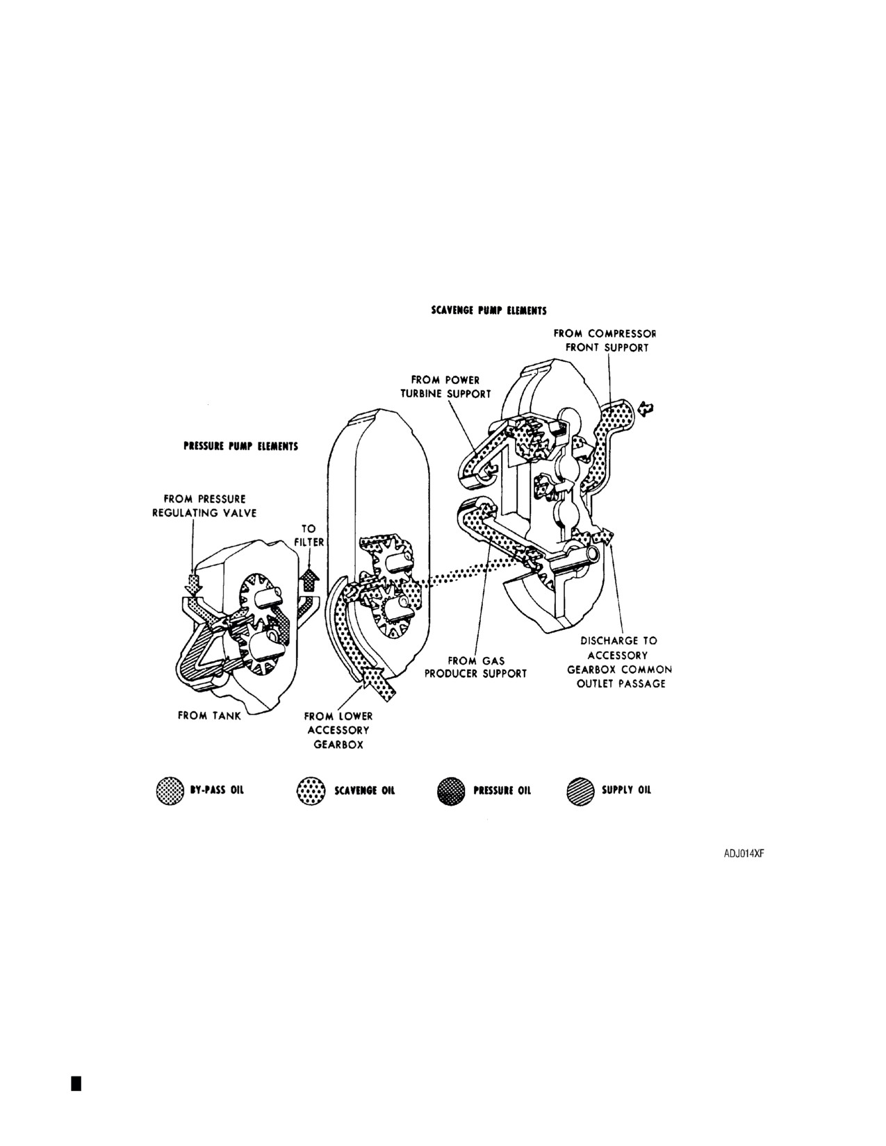
Oil Pump Schematic
FIG. 12
Page 20
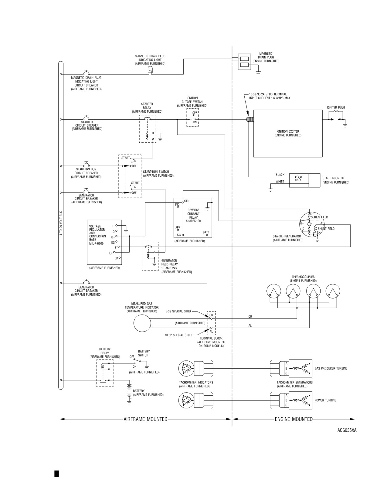
Recommended Electrical Wiring Schematic
FIG. 13
Page 21
A. The effect of anti-icing air flow on engine performance is as follows:
Anti-icing Air Flow On Engine Performance
Type of Operation
Approximate Effect on Performance Available to Pilot at
Power Levels Above 40,000 N1 Speed*
Constant TOT 1280° F (693° C) Max Con-
A 30 hp decrease and a 1000 rpm (1.95%) decrease in N1
tinuous
(gas producer) speed
Constant N1 speed 100% (51,120 rpm)
A 7 hp decrease and a 45° F (25° C) increase in TOT
Constant hp (270) and constant collective
A 300 rpm (0.59%) increase in N1 speed and a 60° F (33° C)
pitch (load) operation
increase in TOT
*These values are for Standard Day Sea Level conditions and will vary with changes in ambient temperature and
altitude. The effects at lower powers and speeds will be only slightly different but still immediate and definite.
9.
Compressor Bleed Air System
The compressor bleed air system permits rapid engine response. The system consists of a compressor
discharge pressure sensing port on the scroll, tubing from the sensing port to the bleed valve, a
compressor bleed control valve (Ref. FIG. 14, and 15 ), and a bleed air manifold on the compressor
case.
Elongated slots between every other vane at the compressor fifth stage, bleeds compressor air into a
manifold which is an integral part of the compressor case. The manifold forms the mounting flange for
the compressor bleed control valve when the compressor case halves are assembled.
Compressor discharge air pressure sensing, for bleed control valve operation, is obtained at a sensing
port on the compressor scroll. The bleed control valve is normally open; it is closed by compressor
discharge pressure. Ref. 16 for bleed control valve opening and closing speeds.
10.
Water-Alcohol System
The Model 250-C18B engine is the same as a Model 250-C18 and the Model 250-C18C is the same as
a Model 250-C18A except that water-alcohol (W/A) augmentation systems have been added. The
systems are added to provide additional takeoff power when operating in high ambient temperatures.
Ref. FIG. 17 and 18 for additional information.
A. Water-Alcohol System Components. The only engine-furnished components of the system are
two injection nozzles which are airframe mounted. Other components of the system are airframe
furnished.
(1) The water-alcohol augmented engine must be equipped with compressor discharge air tubes
PN 6856799 or 6874944. Also, the system requires a 200-mesh filter upstream of the
injection nozzles.
B. Water-Alcohol Injection Nozzles. Each nozzle is designed to flow a nominal 0.625 gpm (2.36 L pm)
at a pressure drop of 50 psi (345 kpa) on a 95°F (35°C) standard day. Flow rates are based on a
water-alcohol mixture of one part by volume methyl alcohol and two parts by volume purified water.
The water and alcohol shall conform to the following standards:
(1) Water. Purified water obtained by the distillation process or water meeting the following
requirements:
Purified Water Requirements
Chemical Requirement
Test Method*
Total solids, ppm
15.0 max
ASTM D-1069-66
Dissolved solids, ppm
10.0 max
ASTM D-1069-66
Total hardness, epm
0.2 max
ASTM D-1126-65
pH
6.5-7.5
ASTM D-1293-65
* Refer 1966 American Society of Testing Materials Standards, Part 23.
Page 22

(2) Methyl Alcohol. Must contain methanol in concentrations not less than 99.85% by weight and
must conform to Federal Specification O-M-232d, grade A. This product is available from
Commercial Solvents Corporation, 245 Park Avenue, New York, N.Y. 10017 or Union Carbide
Corporation Chemicals and Plastics, 270 Park Avenue, New York, N.Y. 10017.
Compressor Bleed Control Valve (Holley Design)
FIG. 14
Page 23

Compressor Bleed Control Valve (Rolls-Royce Design)
FIG. 15
Compressor Bleed Control Valve Operation
FIG. 16

Effect of Water-Alcohol Injection on Shaft Horsepower
FIG. 17

Water-Alcohol Flow Rate-GPM
FIG. 18
Page 26
WARNING: THE MAXIMUM OIL CONSUMPTION LIMIT IS 0.05 U.S. GALLONS PER HOUR (1
QUART IN FIVE HOURS). OPERATION IN EXCESS OF THIS LIMIT IS NOT
PERMITTED. EXCESSIVE OIL CONSUMPTION CAN BE INDICATIVE OF A SERIOUS
INTERNAL OIL LEAK. AN INTERNAL OIL LEAK CAN RESULT IN AN UNDETECTED
INTERNAL OIL FIRE, WHICH WILL RESULT IN A DISASTROUS TURBINE FAILURE.
11. Engine Specifications/Ratings - Engine specifications, limits, and performance ratings are as follows:
Engine Specifications/Ratings
Design power output
317 shp
Design speeds:
Gas producer
100% (51,120 rpm)
Power turbine
100% (35,000 rpm)
Power output shaft
6,000 rpm
Maximum measured gas temperature stabilized (TOT)
1380° F (749° C)
Dimensions:
Length
40.4 in. (1026 mm)
Height
22.5 in. (572 mm)
Width
19.0 in. (483 mm)
Engine weight (dry)
141 lb
(63.96 kg) (250-C18, -C18A)
141.2 lb (64.05 kg) (250-C18B, -C18C)
Maximum oil consumption
0.05 U.S. gal/hr or 1 qt in 5 hours (0.9 liter in 5
hrs)
Performance ratings*
See Tables 1 and 2
* The performance ratings in Table 1 also apply to 250-C18B and 250-C18C engines.
Table 1
250-C18B and 250-C18C Performance Ratings (Standard Sea Level 95° F Ambient Static Conditions)
Ram Power
Measure
Output Shaft-
N1, Gas Pro-
Rating Torque
N2, Power
Specific Fuel Con-
Rated Gas
fower (min)
ducer Speed
at Output
Turbine Speed
Output Shaft
sumption (max)
Temperature
Rating
hp
kW
% rpm
%
rpm
%
rpm
lb/shp- hr mg/W⋅h
Shaft (max)
° F
° C
ft-lb
N⋅m
Takeoff
317
236
100.9
51,600
100
35,000
100
6,000
0.697
423.97
293
397
1380
749
Max Cont
270
201
97.3
49,760
100
35,000
100
6,000
0.706
429.44
249
338
1280
693
(M. C.)
Cruise A
243
181
95.2
48,650
100
35,000
100
6,000
0.725
441.00
249
338
1226
663
(90% M.C.)
Cruise B
203
151
91.8
46,950
100
35,000
100
6,000
0.762
463.50
249
338
1148
620
(75% M.C.)
Ground Idle
35
26
62.6
32,000
75-
26,250-
75-
4,500-
61 lb/hr
27.67kg/
--
--
750±100
399
105
36,750
hr
±55
105
6,300
Flight Auto-
0 max
0 max
62.6
32,000
98.3- 34,417-
98.3-
5,900-
61 lb/hr
27.67kg/
--
--
725±100
385
rotation
106
37,100
106
6,360
hr
±55
Page 27
Table 2
250-C18 and 250-C18C Performance Ratings (Sea Level 95° F Ambient Static Conditions)
Ram Power Rating Torq-
Measured Rated Gas
ue at Output Shaft (max)
Output Shaft
Temperature (max)
Output Shaft (min)
%
(rpm)
° F
°C
Rating
hp
kW
lb-ft
N⋅m
Takeoff*
(Augmented)
310
231
100
6,000
293
397
1380
749
* Augmented takeoffs are limited to ambient temperatures above 40° F (4° C) and shall not exceed five minutes
duration. The above rating is based on a water-alcohol flow rate of 1.25 gallons per minute (gpm) (4.73 l/min)
delivered to the injection nozzles at a pressure differential of 50 psi (345) kPa across each nozzle.
12.
Fuel Specification
WARNING: TO PREVENT ENGINE FUEL SYSTEM CONTAMINATION, WHICH COULD CAUSE
ENGINE FLAMEOUT, AN EXTERNAL LOW PRESSURE FUEL FILTER SHOULD BE
USED ON ANY AIRCRAFT REFUELING FROM REMOTE FUELING SITES (DRUMS
ETC).
CAUTION: NOT ALL NO. 1 DIESEL FUELS, JP-1, OR ARCTIC DIESEL FUELS WILL MEET THE
PRIMARY FUEL SPECIFICATIONS. IN DETERMINING WHETHER OR NOT A GIVEN
FUEL MEETS THESE SPECIFICATIONS, THE BURDEN OF PROOF RESTS WITH
THE OPERATOR AND HIS SUPPLIER.
Primary Fuel
MIL-T-5624, grade JP-4 and JP-5
MIL-T-83133, grade JP-8
ASTM D-1655, Jet B
ASTM D-1655, Jet A or A1
JP-1 fuel conforming to ASTM D-1655,
Jet A
Arctic Diesel Fuel DF-A (VV-F-800B)
conforming to ASTM D-1655, Jet A or
Jet A1
Diesel #1 fuel conforming to ASTM
D-1655, Jet A
CAUTION: MIL-G-5572 FUEL CONTAINING TRICRESYLPHOSPHATE (TCP) ADDITIVE
SHALL NOT BE USED.
Emergency Fuel
MIL-G-5572E, all grades (aircraft boost
pump on; maximum of 6 hours operation
per overhaul period of turbine)
WARNING: AT AMBIENT TEMPERATURES BELOW 40° F (4° C), SOME TYPE OF ANTI-ICE
PROTECTION IS REQUIRED, SUCH AS AN ANTI-ICE ADDITIVE OR A MEANS
OF AIRFRAME FUEL ICE ELIMINATION. ENGINE FLAMEOUT COULD RESULT
FROM FAILURE TO USE ANTI-ICE PROTECTION. (REFER TO THE AIRCRAFT
MANUAL FOR THEIR RECOMMENDATIONS.)
NOTE: JP-4, JP-5 and JP-8 type fuels conforming to MIL-T-5624 or MIL-T-83133A or
later contain an anti-ice additive which conforms to MIL-I-27686 or later and do not
require additional anti-ice additives unless specified by the airframe manufacturer.
Cold Weather
To ensure consistent starts below 4° C
(40° F) the following fuels may be neces-
sary:
MIL-T-5624, grade JP-4
Page 28
Cold Weather - continued
ASTM D-1655, Jet B
AVGAS/Jet A, Jet A1, or JP-5 mixture
(Refer to Cold Weather Fuels, Section II
para10, for mixing/use of cold weather
fuel.)
NOTE: Jet A, A1, JP-5, or JP-8 fuels are not restricted from use at ambient temperatures below 0°F
(-18°C); however, special provisions for starting must be made. (Refer to Aircraft Flight
Manual.) Once started, engine operation on Jet A, Jet A1, JP-5, or JP-8 will be satisfactory in
outside air temperatures down to -25°F (-32°C).
NOTE: Prolonged and uninterrupted operation with only AVGAS mixture will induce lead buildup on
turbine parts. This lead buildup can cause a gradual power reduction; consequently, this
AVGAS mixture should be used only for cold weather operation. During operation with normal
Jet A type fuel, the lead will slowly dissipate.
A. Prist anti-ice additive( MIL-I-27686E) is approved for use in the model 250-C18 series engines if
used in accordance with the additive manufacturer’s instructions and if approved by the airframe
manufacturer.
13.
Oil Specification
A. The 250 series engines are qualified and certified for use with only certain MIL-PRF-7808G,
subsequent MIL-PRF-23699 series, and DOD-85734 series lubricating oils. Vendor brands of
MIL-PRF-7808 series, MIL-PRF-23699 series and DOD-85734 series lubricating oils which have
been engine tested and approved for use in the Model 250 engine are listed para C. Refer to
paragraph B. for the type of oil recommended at specific temperatures.
WARNING: ONLY DISCRETIONARY MIXING OF OILS WITHIN AN OIL SERIES IS PERMITED
WITHOUT A TIME PENALTY. USE OF MIXED OILS FROM DIFFERENT SERIES IN
AN ENGINE IS LIMITED TO FIVE HOURS TOTAL RUNNING TIME DURING ONE
OVERHAUL PERIOD. ADEQUATE MAINTENANCE RECORDS MUST BE
MAINTAINED TO ENSURE THAT THE FIVE HOUR LIMIT IS NOT EXCEEDED.
FAILURE TO COMPLY WITH OIL MIXING RESTRICTIONS CAN RESULT IN ENGINE
FAILURE.
CAUTION: IF BRANDS OF OILS ARE CHANGED, IT IS RECOMMENDED THIS CHANGE BE
ACCOMPLISHED GRADUALLY USING A ‘‘TOP-OFF’’ METHOD OR BY DRAINING
AND REFILLING. IN THE TOP-OFF METHOD, OIL OF THE NEW BRAND IS ADDED
AS OIL IS CONSUMED BY THE ENGINE. IN THE EVENT OIL BRANDS ARE
CHANGED BY DRAINING AND REFILLING THE LUBRICATION SYSTEM, WATCH
FOR POSSIBLE BYPASS INDICATIONS. THESE INDICATIONS COULD BE AN
INDICATION OF CARBON OR COKE, WHICH WAS FORMED DURING PREVIOUS
OPERATION, BEING DISLODGED DURING OPERATION FOLLOWING THE CHANGE.
CAUTION: IF HEAVY CARBON OR COKE DEPOSITS ARE FOUND ON THE ENGINE FILTER
DURING REGULAR INSPECTIONS, IT IS RECOMMENDED THE FILTERS BE
REPLACED; CONTINUE TO MONITOR BYPASS INDICATORS.
CAUTION: TO DECREASE THE LIKELIHOOD FOR CARBON OR COKE DEPOSITS BEING
DISLODGED DURING THE CHANGEOVER TO ‘‘3RD GENERATION’’ OILS (E.G.
MOBIL JET 254), THESE CHANGEOVERS SHOULD ONLY BE MADE WHEN THE
ENGINE IS NEW OR REPAIRED, TO THE EXTENT THE LUBRICATION PASSAGES
AND SUMPS HAVE BEEN CLEANED AND FLUSHED
Page 29
CAUTION:
WHILE CONSIDERABLE LABORATORY DATA IS AVAILABLE TO DEMONSTRATE
THE COMPATIBILITY OF ONE SYNTHETIC TURBINE OIL WITH OTHER TURBINE
OILS MEETING THE SAME SPECIFICATION (EXPERIENCE ALSO DEMONSTRATES
THIS PROPERTY), THE INDISCRIMINATE MIXING OF APPROVED OILS DURING
THE OPERATIONAL USE OF THE OIL IS NOT RECOMMENDED. HOWEVER, THERE
MAY BE CIRCUMSTANCES WHERE EMERGENCY TOP-OFF, INADVERTENT
MIXING, OR CHANGEOVER BY ‘‘TOP-OFF’’ TO ANOTHER BRAND MAY OCCUR.
THESE ARE ACCEPTED PRACTICES.
CAUTION:
FAILURE TO COMPLY WITH OIL MIXING RESTRICTIONS CAN RESULT IN ENGINE
FAILURE.
CAUTION:
REMOVE AND INSPECT THE OIL FILTER AFTER THE FIRST 25 HOURS OF ENGINE
OPERATION IF THE TYPE OF OIL (MIL-PRF-7808, MIL-PRF-23699, OR DOD-
85734) IS CHANGED. REPEAT THE FILTER INSPECTION EACH 25 HOURS AS
REQUIRED UNTIL EXCESSIVE CARBON PARTICLE ACCUMULATION SUBSIDES.
CAUTION:
THE FILTER INSPECTION IS TO DETERMINE IF COKE, WHICH WAS FORMED
DURING PREVIOUS OPERATION, IS BEING DISLODGED DURING THE FIRST
OPERATION FOLLOWING THE OIL CHANGE.
CAUTION:
IF HEAVY CARBON DEPOSITS ARE OBSERVED ON THE ENGINE FILTER, IT IS
SUGGESTED THAT THE ENGINE OIL BE CHANGED AGAIN. THE OIL IS TO BE
DRAINED WHEN THE OIL IS HOT TO OBTAIN THE MAXIMUM BENEFIT. THE 25
HOUR OIL MONITORING IS TO CONTINUE UNTIL THE NEXT OIL CHANGE PERIOD.
CAUTION:
USE OF OILS WHICH ARE NOT INCLUDED IN THE APPROVED OILS LISTING, OR
FAILURE TO DRAIN OIL WITHIN THE PRESCRIBED INTERVAL GIVEN IN TABLE 604,
72-00-00, ENGINE-INSPECTION/CHECK WILL BE CONSIDERED AS MISUSE
UNDER ITEM (4) OF THE WARRANTY POLICY.
NOTE:
Because of availability, reduced coking, and better lubricating qualities at higher
temperatures, qualified MIL-PRF-23699 oils are preferred for use in Model 250 engines.
Check the aircraft oil quantity within 15 minutes of engine shutdown to avoid a false
indication of excessive oil consumption. If the 15 minutes has been exceeded, motor the
engine for 30 seconds with the starter before checking tank quantity. Motoring normally
scavenges oil from the gearbox back to the aircraft oil tank. Check the airframe flight
manual; some installations may require engine to be operated for at least a minute at
ground idle to assure proper scavenging of the engine gearbox.
Always refer to the airframe flight manual for proper oil servicing instructions; specific
requirements may vary for different models.
B.
Cold Weather Lubrication
The types of oil recommended at specific ambient temperatures are as follows:
Ambient Temperature
Oil Series
0°C (32°F) and above
MIL-PRF-23699C or subsequent
preferred
0°C (32°F) to -40°C (-40°F)
MIL-PRF-23699C or subsequent
preferred or MIL-PRF-7808G or
subsequent
-40°C (-40°F) and below
MIL-PRF-7808G or subsequent only
-40°C (-40°F) to135°C (275°F)
DOD- 85734
Page 30
C. Approved Oils
Manufacturer’s Designation & Address
Manufacturer’s Designation & Address
MIL-PRF-7808 Series
MIL-PRF-23699 Series (cont)
(Formerly MIL-L-7808)
(Formely MIL-L-23699)
American PQ Lubricant 689
Caltex RPM Jet Engine Oil 5
American Oil & Supply Co.
Caltex Petroleum Corporation
238 Wilson Avenue
380 Madison Avenue
Newark, New Jersey 07105
New York, New York 10017
Brayco 880
Castrol Aero Jet5
Castrol Inc.
Specialty Products Division
Specialty Products Division
1001 West 31st Street
16715 Von Karman Ave, Suite 230
Dowers Grove, IL 60515
Irving, California 92714
EXXON Turbo Oil 2389
Cheveron Jet Engine Oil 5
EXXON Company, U.S.A.
Chevron International Oil Company
P.O. Box 2180
555 Market Street
Houston, Texas 77252-2180
San Francisco, California 94105
Mobil Avrex S Turbo 256
EXXON Turbo Oil 2380
Mobil OIl Corporation
EXXON Company, USA
3225 Gallows Road
P.O. Box 2180
Fairfax, Virginia
22037
Houston, Texas 77252-2180
Mobil RM-184A and
Hatcol 3211
Mobil RM-201A
Hatcol Corporation
Mobil Oil Corporation
King George Post Road
3225 Gallows Road
Fords, New Jersey 08863
Fairfax, Virginia
22037
Stauffer Jet 1
Mobil Jet Oil II
Stauffer Chemical Co.
Mobil Oil Corporation
380 Madison Avenue
3225 Gallows Road
New York, New York 10017
Fairfax, Virginia
22037
Stauffer Jet II (Castrol 205)
Stauffer Chemical Company
MIL-PRF-23699 Series
380 Madison Avenue
(Formerly MIL-L-23699)
New York, New York 10017
Aeroshell/Royco Turbine Oil 500
Turbonycoil 600 (TN600)
Royal Lubricants Company, Inc.
NYCO S.A.
River Road, P.O. Box 518
66, Champs-Elysees-51
East Hanover, New Jersey 07936
Rue De Ponthieu
75008 Paris
American PQ Lubricant 6700
American Oil and Supply Co.
238 Wilson Avenue
Newark, New Jersey 07105
Brayco 899
Castrol Inc.
Specialty Products Division
16715 Von Karman Ave., Suite 230
Los Angeles, California 90032
Page 31
Manufacturer’s Designation & Address
Manufacturer’s Designation & Address
MIL-PRF-23699F Series
High Thermal Stability (HTS)
DOD-85734 Series
Aeroshell/Royco Turbine Oil 560
Aeroshell/Royco Turbine Oil 555
Royal Lubricants Company, Inc.
Royal Lubricants Company, Inc.
River Road, P.O. Box 518
River Road , P.O. Box 518
East Hanover, New Jersey 07936
East Hanover, New Jersey 07936
Aeroshell Turbine Oil 560
NOTE: Long term use of Aeroshell/Royco
Shell International Petroleum Co., Ltd.
555 oil may increase the probability of
International Aviation Sales Division
silicone rubber seal leakage in the
Shell Centre
accessory gearbox.
London, SEI 7NA, England
EXXON ETO 2197 (BPTO 2197)
Aeroshell Tubine Oil 555
Air BP
Shell International Petroleum Co., Ltd
BP Exploration & Oil, Inc
International Aviation Sales Division
Maple Plaza II-1N
Shell Centre
Six Campus Drive
London, SEI 7NA, England
Parsippany, NJ 07054
Mobil Jet Oil 254 and
NOTE: Long term use of Aeroshell 555 oil
Mobil Jet Oil 291
may increase the probability of silicone
Mobil Oil Corporation
rubber seal leakage in the accessory
3225 Gallows Road
gearbox.
Fairfax, Virginia 22037
14.
Engine Trend Check Analysis
A.
The trend check analysis provides a method for the operator to monitor engine health. The trend
check will also allow the operator to more effectively predict when preventative maintenance is
required and schedule some maintenance actions that were formerly unscheduled.
B.
Rolls-Royce Engine Company encourages all operators on a voluntary basis to utilize performance
trending to supplement their regular maintenance program. It should be noted that the use of
performance trending does not change the requirement to operate the engine within established
limits and according to applicable publications. Aircraft manufacturer engine trending procedures
that are published in the applicable FAA approved flight manuals can be used in lieu of the
procedure given in this manual if they are Rolls-Royce approved. (Refer to Aircraft Manufacturer
Trend Check-Alternate Procedure, Section II.)
C.
The analysis given in the Trend Check Procedure, Section II, Engine Inspection/Check provides
the necessary guidance, procedures, check lists, correction Table’s and graphic examples required
to set up an engine trend check program. A trend check program can be initiated at any point in an
engine’s life. The effectiveness of the trending program is dependent on the quality of the
uncorrected data. Anything that causes the inflight data to be in error will reflect adversely on the
effectiveness of the program.
D.
Consideration should be made for tolerances on the accuracy of aircraft installed instruments.
Instrument error could affect measured performance by approximately the following:
(1)
4% below actual power available for every +5° C error in outside air temperature (OAT). Use a
precision mercury type thermometer in the immediate vicinity of the OAT probe. Shade both
thermometers for a minimum of 15 minutes before taking a reading. Compare accuracy of
installed OAT gauge.
(2)
1% below actual power available for every 300 feet error in pressure altitude. Determine
pressure altitude by averaging the readings of altimeters of known accuracy on the flight deck.
Page 32
(3)
2% below power available for every +6° C error in TOT. Check calibrate the TOT system and
gauge.
(4)
2% below actual power available for every +2% error in torquemeter. Check accuracy of
torque measuring system.
Page 33
ENGINE OPERATION
1.
Engine Operating Precautions
WARNING: THE PRIMARY APPLICATION OF THIS TURBOSHAFT ENGINE IS TO
POWER A HELICOPTER OR ROTOCRAFT. A HEIGHT-VELOCITY DIAGRAM, AS
REQUIRED BY REGULATION AND PREPARED BY THE AIRFRAME
MANUFACTURER, IS PUBLISHED IN THE AIRCRAFT FLIGHT MANUAL
PERFORMANCE SECTION FOR NORMAL CATEGORY ROTORCRAFT. THE
OPERATOR MUST BECOME FAMILIAR WITH THIS DIAGRAM TO DETERMINE WHAT
ALTITUDES AND AIRSPEEDS ARE REQUIRED TO SAFELY MAKE AN
AUTOROTATIONAL LANDING IN CASE OF POWER LOSS OR ENGINE FAILURE.
THE ALTITUDE-AIRSPEED COMBINATIONS WHERE A SAFE AUTOROTATIONAL
LANDING MAY NOT BE POSSIBLE ARE REPRESENTED BY THE SHADED OF
CROSS-HATCHED AREA OF THE DIAGRAM.
WARNING: SNOW OR ICE SLUGS CAN CAUSE THE ENGINE TO FLAME OUT. BE SURE
AVAILABLE PREVENTIVE EQUIPMENT IS INSTALLED AND IN PROPER WORKING
ORDER WHEN FLYING IN CONDITIONS WHERE SNOW OR ICE BUILDUP MIGHT
OCCUR.
WARNING: CONSULT THE AIRCRAFT FLIGHT MANUAL FOR REQUIRED EQUIPMENT AND
PROCEDURES FOR FLIGHT IN FALLING/BLOWING SNOW.
WARNING: SAND AND DUST WILL ERODE COMPRESSOR VANES AND CAUSE THEM TO FAIL.
WARNING: SALT LADEN HUMIDITY AND CHEMICALS WILL CORRODE COMPRESSOR BLADES
AND VANES AND CAUSE THEM TO FAIL.
A. Observe the following precautions to reduce the danger of personnel injury or damage to the
engine.
(1) Before operating the engine, check the air inlet for foreign objects. (Refer to Compressor Inlet
Air Blockage, Section III.)
(2) If the engine does not operate within the limits of Operating Limits, para 2, take the designated
action.
(3) If the aircraft is frequently operated in dusty or sandy areas, periodic erosion inspection is
recommended. (Refer to Erosion Inspection, Section III.)
(4) If a flameout has been experienced as the possible result of snow, ice, or water ingestion refer
to Snow Ingestion Inspection, Section III.
(5) If the aircraft is being operated following an extended period of inactivity, refer to Special
Inspections, Section III, Table 9 for recommended action.
(6) If the engine is operated in a salt water environment it must be subjected to a water wash.
(Refer to Compressor Salt Water Contamination Removal, Section III.)
(7) If the installed engine will be shut down for more than five calendar days the compressor must
receive an application of preservative. (Refer to Compressor Preservation, Section III.)
2.
Engine Operating Limits
WARNING: TO PREVENT SERIOUS ENGINE MALFUNCTION OR CRUCIAL LOSS OF POWER, DO
NOT OPERATE THE ENGINE IN EXCESS OF ANY SPECIFIED LIMIT.
NOTE: Operators may be faced with an engine that meets all specification power requirements in a
certified test cell; but, apparently fails to meet the minimum installed power required by the
aircraft flight manual. Please refer to the Aircraft Manual for other system troubleshooting.
NOTE: Operators should be aware that the FAA requires the Rolls-Royce Authorized Maintenance
Centers (AMC) to deliver engines of at least “specification horsepower” only after complete
engine overhaul.
Page 1

3.
Engine Speed
If any of the following limits are exceeded, send the designated engine components to repair/overhaul.
Record the extent of overspeed in the engine log book.
Engine Speed
Limit
Component
N1 (Gas Producer)
104% - max continuous
None
104-105% -15 sec max
None
104-105% - over 15 sec
Turbine and compressor
Over 105% - not allowed
Turbine and compressor
N2 (Power Turbine)
Limits as shown in FIG. 1.
Turbine
Complete loss of output shaft load
Turbine and gearbox
120% (42,000 rpm) or maximum indication shown
Turbine and gearbox
on N2 tachometer, whichever is first
Maximum Allowable Output Shaft Speeds
FIG. 1
Page 2
4.
Power Turbine Speed Restrictions
The following N2 speed restrictions are applicable to engines having the power and accessories gearbox
assemblies with the following serial numbers: CAG 20183, 20185, 20193 through 20265, 20508, 21001
through 21395, 21600 through 21706, and 21800 through 21803. The restrictions shall be lifted only
after the gearbox has been reworked in accordance with Rolls-Royce Commercial Engine Bulletin 250
CEB-90.
A. Adjust N1 speed at ground idle so N2 speed does not exceed 71% rpm.
B. Avoid steady state operation at any flight or ground condition, other than ground idle or practice
autorotation, at engine N2 speeds below 98% or above 102% rpm.
5.
Temperature
WARNING: HOT STARTS OR AFTERFIRES AFTER SHUTDOWN CAN CAUSE TURBINE BLADE
AND WHEEL DAMAGE RESULTING IN ENGINE FAILURE.
A. Refer to Table 1 for the measured gas temperature limits and the action to be taken when they are
exceeded.
TABLE 1
Measured Gas Temperature Limits (TOT)
Temperature Range
Time
Maintenance Action
Steady State
749°C (1380° F)
Takeoff (5 min.)
If steady-state time or condition
limits are exceeded, inspect tur-
bine.
(2)
749°C (1380° F)
30 Minute Power (1)
693°C (1280° F)
Max Continuous and Below
During Starting and Shutdown
Up to 749° C (1380° F)
No limit
None
749-927° C
(1380-1700° F)
Over 10 sec (3)
Inspect turbine (2)
927-999° C (1700-1830° F)
Not allowed (3)
Inspect turbine (2)
Over 999° C (18300° F)
Not allowed
Remove turbine for heavy mainte-
nance or overhaul.
NOTE: Refer to Section III, Troubleshooting (item 4) when start temperature consistently exceeds
843° C (1550° F).
During Power Transient
Up to 693° C (1280° F)
No limit (Transient only)
None
693-749° C (1280-1380° F)
Until stabilized (5 min max)
None
749-843° C (1380-1550° F)
0 to 6 sec (intentional use of tem-
None
peratures in excess of 749°C
(1380° F) is not recommended)
749-843° C (1380-1550° F)
Over 6 sec
Inspect turbine (2)
843-927° C (1550-1700° F)
Not allowed (3)
Inspect turbine (2)
Over 927° C (1700° F)
Not allowed (3)
Remove turbine for heavy mainte-
nance or overhaul.
(1) Applicable only in multi-engine helicopters when meeting one engine inoperative climb requirements.
(2) Refer to the Special Inspections Section III, Table 9, Item 11 or 13. Also, record temperature and duration
in the Engine Log Book (pink pages, Turbine Assembly Part IV, Inspection Record).
Page 3
(3) Momentary peak temperature of 927°C (1700°F) is permitted for no more than one second.
NOTE: The time-at-temperature limits are not additive. The repeated, intentional use of transient
temperature limits can result in reduced turbine life and is not recommended.
6.
Torque
A. If max torque limit of 365 hp (273 kW)-320 lb ft (434 N.m) is exceeded for more than 10 seconds,
the gearbox must be removed and sent to an Authorized Maintenance Center to be overhaul
inspected. Refer to FIG. 2 for torquesensor oil pressure-to-shaft power relationship and to Table 2
for torque limits.
TABLE 2
Output Shaft Torque Limit
Torque
Pressure
Power
Time Limit
lb ft
N.m psi
kPa hp
kw
320
434
109
752
365
273
10 sec
293
397
100
689
335
250
30 min
249
337
85
586
284
212
Continuous
7.
Oil Pressure and Temperature
A.
If the oil pressure is not within the following limits, refer to Section III, Table 6, Troubleshooting.
a. 97% N1 speed and above
110-130 psig (758-896 kPa)
b.
78 to 97% N1 speed
90-130 psig (621-896 kPa)
c. Below 78% N1 speed
50 psig min (345 kPa)
d. During start
a positive indication must be obtained
when 59% (idle) is reached.
NOTE: During cold weather operation, 150 psig (1034 kPa) main oil pressure is allowable
following an engine start. When the 130 psig (896 kPa) limit is exceeded, operate engine
at minimum power until normal oil pressure limits are attained.
NOTE: If the engine has been operated with less than the required oil pressure, except for
momentary fluctuation, inspect the oil system in accordance with Low Oil Pressure
Operation, Section III.
B.
Oil temperature shall be within the following range. (If the maximum limit is exceeded, refer to Oil
Temperature Limit Exceeded, Section III, for corrective action.)
a. Minimum starting
MIL-PRF-7808F or later
-54°C
(-65°F)
MIL-PRF-23699
-40°C
(-40°F)
b. Maximum
107°C
(225°F)
c. Minimum flight operation
0°C
(32°F)
(Providing engine oil pressure is within the specified limits of para 7 a.)
8.
Pressure Altitude And Ambient Temperature
A. The engine will start and operate satisfactorily at conditions of ambient pressure and temperature
as shown in FIG. 3.
Page 4

Torquesensor Oil Pressure and Shaft Power Relationship
FIG. 2
Page 5

Engine Operating Limits
FIG. 3
Page 6
9.
Engine Operating Procedures
WARNING: TO PREVENT ENGINE FUEL STARVATION AND SUBSEQUENT FLAMEOUT, ANY
AIRCRAFT REQUIRING FUEL BOOST PUMP(S) SHOULD USE THESE PUMPS AT
ALL TIMES DURING FLIGHT OR AS DIRECTED IN THE AIRCRAFT FLIGHT MANUAL.
WARNING: TO PREVENT CRUCIAL DELAY IN REGAINING POWER IF AN ENGINE FLAMEOUT
IS ENCOUNTERED, AIRCRAFT EQUIPPED WITH AN AUTO-RELIGHT SYSTEM
SHOULD KEEP THAT SYSTEM ACTIVATED AT ALL TIMES WHILE THE AIRCRAFT IS
IN FLIGHT.
A. Start and Ground Idle
The following procedures pertain to operation of the engine at: start and ground idle; power range;
practice autorotation, descent and landing; stopping; and during an emergency.
WARNING: TO ENSURE ADEQUATE WARNING OF POSSIBLE EMERGENCY ENGINE
OPERATING CONDITIONS, VERIFY THAT THE ENGINE WARNING SYSTEMS
(ENGINE-OUT HORN, FILTER BYPASS LIGHT, AND CHIP DETECTOR LIGHT) ARE
OPERABLE BEFORE EACH FLIGHT.
WARNING: OVERTEMPERATURE STARTS OR AFTERFIRES AFTER SHUTDOWN WILL CAUSE
CRACKS IN THE 1ST-STAGE WHEEL RIM. THESE CRACKS CAN EVENTUALLY
CAUSE A SECTION OF THE WHEEL TO BREAK OUT AND EXIT THE ENGINE WITH
POTENTIALLY DISASTROUS RESULTS.
NOTE: For the ultimate safety of all personnel who come in close proximity with the engine in the
future, it is the responsibility of the pilot and maintenance personnel to record and take
recommended corrective action when an overtemperature occurs.
CAUTION: BEFORE THE ENGINE IS OPERATED, MAKE CERTAIN THE COMPRESSOR
INLET IS FREE OF DEBRIS. ALSO, MAKE CERTAIN THE COMPRESSOR
ROTOR IS NOT FROZEN, IF THE AIRCRAFT IS IN A FREEZING ATMOSPHERE.
Preflight Inspections. Before starting the engine, make a preflight inspection. (Refer to Preflight
and Postflight Inspections, Section III, Table 7.)
(1) Two starting procedures are provided for the engine. The first procedure is for normal starts in
ambient temperatures above 4°C (40°F). (Refer to Normal Start Procedure sub-para 2.) The
second procedure is for starts in ambient temperatures between plus 4° and minus 54°C (39°
and minus 65°F). (Refer to Cold Weather Start Procedure, sub-para 3.)
(2) Normal Start Procedure. Start the engine as follows:
(a) Rotate the twist grip to FUEL OFF and turn all switches off.
(b) Position the aircraft collective pitch (load) control in the minimum position.
(c) Turn on the aircraft switches required to provide fuel to the engine.
NOTE: It is recommended that the residual TOT be no more than 150°C (302°F) when
the throttle is opened and light off is attempted. Residual TOT can be readily
reduced to or below 150°C (302°F) by motoring engine with the starter.
CAUTION: DURING A START, THE TWIST GRIP MUST NEVER BE ROTATED OUT OF
THE FUEL OFF POSITION UNTIL AFTER THE STARTER AND IGNITION
EXCITER HAVE BEEN ENERGIZED AND THE DESIRED CRANKING SPEED
HAS BEEN ATTAINED. TO DO SO MIGHT RESULT IN AN EXPLOSIVE
LIGHTOFF OR OVERTEMPERATURE START.
Page 7
CAUTION: AN ENGINE FIRE (WITH THE RESULTANT FLAME EMANATING FROM THE
TAILPIPE), CAN OCCUR DURING START IF THE COMBUSTION CHAMBER
BECOMES OVERLOADED WITH FUEL BEFORE IGNITION TAKES PLACE.
TO EXTINGUISH THE FIRE, CONTINUE TO MOTOR THE ENGINE USING
THE STARTER WITH THE THROTTLE FULLY CLOSED AND THE MAIN
FUEL SWITCH OFF.
CAUTION: MONITOR OIL PRESSURE DURING START. DAMAGE TO ROTOR
BEARINGS CAN RESULT IF A POSITIVE INDICATION OF OIL PRESSURE
IS NOT OBTAINED BY THE TIME IDLE SPEED IS REACHED.
(d) Energize the starter motor and ignition exciter.
CAUTION: A START SHOULD NOT BE ATTEMPTED AT N1 SPEEDS BELOW 12%.
STARTING AT N1 SPEEDS LESS THAN 12% INCREASES THE
POSSIBILITY OF EXCEEDING ENGINE TEMPERATURE LIMITS.
CAUTION: FOR ENGINES INCORPORATING LOW ENERGY EXCITERS,
OPERATING TIME LIMITS ARE AS FOLLOWS: 2 MINUTES ON, 3
MINUTES OFF; 2 MINUTES ON, 23 MINUTES OFF.
CAUTION: HIGH ENERGY IGNITION EXCITERS ARE QUALIFIED FOR
CONTINUOUS DUTY OPERATION. HOWEVER, USE OF THE
IGNITION SYSTEM ON A CONTINUOUS BASIS IS NOT
RECOMMENDED BECAUSE OF DEGRADATION OF THE SPARK
IGNITER.
(e) As N1 rpm accelerates through 12-15% N1, move the twist grip to the IDLE position to
begin fuel flow.
NOTE: Do not wait for N1 peak out. Introduce fuel immediately upon reaching desired
N1 speed. Delay in moving the throttle to the idle detent may diminish battery
capacity early in the start cycle.
NOTE: It is recommended that residual TOT be no more than 150°C (302°F) when the
throttle is opened and lightoff is attempted. Residual TOT can be readily
reduced to or below 150°C (302°F) by motoring the engine with the starter.
CAUTION: IF THE N2 TURBINE IS NOT ROTATING BY 25% N1 SPEED ABORT THE
START. A SECOND OR THIRD START ATTEMPT MAY BE MADE; IF THE
CONDITION STILL EXISTS REFER TO SECTION III, TROUBLESHOOTING
TABLE 6, ITEM 58.
CAUTION: IF THE ENGINE HAS BEEN SHUT DOWN FOR MORE THAN 15 MINUTES,
STABILIZE AT IDLE SPEED FOR ONE MINUTE BEFORE INCREASING
POWER.
(f)
De-energize the starter and ignition exciter when 58% N1 speed is reached. The start is
completed when a stabilized N1 speed of 59-65% is reached. Completion of the start
normally occurs 25 to 60 seconds after starter engagement. A positive indication of oil
pressure must be obtained by this point in the start. If it is not, shut down the engine and
check to be sure that oil is available at the power and accessories gearbox inlet. Mon-
itor the measured gas temperature; do not exceed the limits of Table 1.
NOTE: If a stagnated start is experienced, shut down then repeat start procedure.
NOTE: If overtemperature is experienced, turn the twist grip to FUEL OFF and motor
the engine without ignition for ten seconds.
NOTE: The start should be complete in one minute; however, if N1 and N2 are
accelerating and TOT is within limits, the start may be continued longer than
one minute.
NOTE: Monitor N1, and TOT when turning generator switch ON. If N1 decays below 60
percent, or TOT approaches 810°C (1490°F), turn generator OFF and increase
N1 speed with throttle to 70 percent, then reset generator to ON.
Page 8
(3)
Cold Weather Start Procedure. Some general practices recommended for improved cold
weather operation of the 250-C18 series engines are as follows:
(a) When the aircraft is parked, use appropriate covers over the inlet ducts, exhaust stacks,
etc.
(b) At temperatures below 40°F (4°C), use JP-4 or commercial Jet B fuel if available. As an
alternate, use the AVGAS-jet fuel mixture described in Cold Weather Fuels, para 10.
NOTE: Use fuel containing an anti-ice additive whenever engine operations are
conducted below 4°C (40°F).
CAUTION: DO NOT USE AN OPEN FLAME HEATER TO PREHEAT THE ENGINE OR
BATTERY.
(c) When the aircraft has been cold soaked at temperatures below 4°C (40°F), use an
auxiliary power source for faster more satisfactory starts, if equipment is available and
conditions allow,.
(d) If the aircraft has been cold soaked at temperatures below minus 18°C (0°F) and a
battery start must be made, preheat the engine fuel control area and battery if equipment
is available and conditions allow.
(e) If the aircraft has been cold soaked and a battery start must be made without preheating
the battery, remove and store the battery until it is required if conditions allow. Store the
battery in an area where it can be maintained or warmed to a temperature above ambient
outside conditions or to approximately 21°C (70°F).
(f)
If stagnated starts are encountered, enrich the starting fuel flow in accordance with the
start derichment adjustment procedure in Fuel Control Adjustments, Section III .
(4)
During cold weather, start the engine as follows:
(a) Rotate the twist grip to FUEL OFF and turn all switches off.
(b) Position the aircraft collective pitch (load) control in the minimum position.
(c) Turn on the aircraft switches required to provide fuel to the engine.
CAUTION: DURING A START, TWIST GRIP MUST NEVER BE ROTATED OUT OF THE
FUEL OFF POSITION UNTIL AFTER THE STARTER AND IGNITION
EXCITER HAVE BEEN ENERGIZED AND THE DESIRED CRANKING SPEED
HAS BEEN ATTAINED. TO DO SO MIGHT RESULT IN AN EXPLOSIVE
LIGHTOFF OR OVERTEMPERATURE START.
CAUTION: AN ENGINE FIRE (WITH RESULTANT FLAME EMANATING FROM THE
TAILPIPE) CAN OCCUR DURING START IF THE COMBUSTION CHAMBER
BECOMES OVERLOADED WITH FUEL BEFORE IGNITION TAKES PLACE.
TO EXTINGUISH THE FIRE, CONTINUE TO MOTOR THE ENGINE USING
THE STARTER, WITH THE THROTTLE FULLY CLOSED AND THE MAIN
FUEL SWITCH OFF.
CAUTION: MONITOR OIL PRESSURE DURING START. DAMAGE TO ROTOR
BEARINGS CAN RESULT IF A POSITIVE INDICATION OF OIL PRESSURE
IS NOT OBTAINED BY THE TIME IDLE SPEED IS REACHED.
(d) Energize the starter motor and ignition exciter.
CAUTION: A START SHOULD NOT BE ATTEMPTED AT N1 SPEEDS BELOW 12%.
STARTING AT N1 SPEEDS LESS THAN 12% INCREASES THE POSSIBILITY
OF EXCEEDING ENGINE TEMPERATURE LIMITS.
CAUTION: FOR ENGINES INCORPORATING LOW ENERGY EXCITERS, OPERATING
TIME LIMITS ARE AS FOLLOWS: 2 MINUTES ON, 3 MINUTES OFF; 2
MINUTES ON, 23 MINUTES OFF.
CAUTION: HIGH ENERGY IGNITION EXCITERS ARE QUALIFIED FOR CONTINUOUS
DUTY OPERATION. HOWEVER, USE OF THE IGNITION SYSTEM ON A
CONTINUOUS BASIS IS NOT RECOMMENDED BECAUSE OF
DEGRADATION OF THE SPARK IGNITER.
(e) At the desired N1 cranking speed, rotate the twist grip to the IDLE position. Use the
following guide for desired N1 starting speed versus outside air temperature.
N1 rpm %
Temperature ° F
(° C)
15
Above 45
7
13
0 to 44
-18 to +7
12
Below -1
-18
NOTE: Due to the variation in jet fuels available for commercial operation, in cold
weather the engine may experience a short delay before lightoff after the twist
grip is rotated to the IDLE position. This delay should be less than three
seconds regardless of the type of fuel used. If the lightoff delay exceeds three
seconds, return the twist grip to FUEL OFF and continue to motor the engine
with the starter for thirty seconds to remove excess fuel from the combustion
section.
(f)
De-energize the starter and ignition exciter when 58% N1 speed is reached. The start is
completed when a stabilized N1 speed of 59 to 65% is reached. Completion of the start
normally occurs 25 to 60 seconds after starter engagement.
CAUTION:
A POSITIVE INDICATION OF OIL PRESSURE MUST BE OBTAINED BY THIS
POINT IN THE START. IF IT IS NOT, SHUT DOWN THE ENGINE AND
CHECK TO BE SURE THAT OIL IS AVAILABLE AT THE POWER AND
ACCESSORIES GEARBOX INLET.
CAUTION:
MONITOR MEASURED GAS TEMPERATURE. DO NOT EXCEED THE
LIMITS OF TABLE 1. IF OVERTEMPERATURE IS EXPERIENCED, TURN
THE TWIST GRIP TO FUEL OFF AND MOTOR THE ENGINE WITHOUT
IGNITION FOR 10 SECONDS.
CAUTION:
IF THE MAIN ROTOR IS NOT ROTATING BY 25% N1 SPEED ABORT THE
START. A SECOND OR THIRD START ATTEMPT MAY BE MADE; IF THE
CONDITION STILL EXISTS. REFER TO SECTION III, TROUBLESHOOTING,
TABLE 6, ITEM 58.
CAUTION:
IF THE ENGINE HAS BEEN SHUT DOWN FOR MORE THAN 15 MINUTES,
STABILIZE AT IDLE SPEED FOR ONE MINUTE BEFORE INCREASING
POWER.
NOTE:
In some instances N1 may accelerate slowly through the 25-30% speed range
on a battery start after an engine has been cold soaked and not preheated. If
the start is not completed within the starter engagement time limits, shut down
the engine. Before attempting the next start, wait for the starter duty cycle limits
to pass or for one minute, whichever is longer. This wait will allow residual heat
from the previous start attempt to soak back into the engine and battery that
improve conditions for the next start attempt.
Page 10
B.
Power Range
CAUTION: BE SURE THE N2 SPEED RESTRICTIONS GIVEN IN POWER TURBINE SPEED
RESTRICTIONS, PARA 4 ARE OBSERVED.
CAUTION: DECREASING COLLECTIVE TO THE LOW POWER RANGE WILL RESULT IN AN
N2/NR INCREASE. IF THE RPM IS RESET WITH THE BEEP SWITCH, LOW
N2/NR RPM CAN RESULT WHEN COLLECTIVE IS INCREASED TO THE HIGH
POWER RANGE UNLESS THE BEEP SWITCH SETTING IS RETURNED TO
NEAR THE PREVIOUS BEEP POSITION.
(1) During operation in the power range place the twist grip in the maximum position and utilize
engine power with the collective pitch. Vary the pitch to avoid exceeding the measured gas
temperature and torque limits given in Tables 1 and 2 or the N2 speed limit given in FIG. 1. It
is recommended that large collective increases be made over a 2 second time period to avoid
momentary N2/NR droop.
C.
Augmented Takeoff
CAUTION: AUGMENTED TAKEOFFS ARE LIMITED TO AMBIENT TEMPERATURES ABOVE
4°C (40°F) AND SHALL NOT EXCEED FIVE MINUTES IN DURATION.
(1) Operation of Water-Alcohol System.
(a) Make a normal engine start. Idle the engine one minute before increasing power.
CAUTION: DO NOT MAKE RAPID POWER DECELERATIONS OR OPERATE N2 AT
LESS THAN 95% SPEED WHILE USING WATER-ALCOHOL
AUGMENTATION.
(b) Rotate twist grip to full open and increase TOT to 693°C (1280°F) then turn on the
water-alcohol system. (Power will remain steady while the TOT will decrease.) Adjust
power to desired setting but do not exceed 749°C (1380°F) or the maximum torque limit.
NOTE: Acceleration time to augmented Takeoff power will require approximately two
seconds more than acceleration time to nonaugmented Takeoff power.
(c) Before turning off the water-alcohol system, reduce TOT to not less than 693°C (1280°F).
D.
Practice Autorotation Descent And Landing
NOTE: If there is any doubt that the deceleration check was made during shutdown after the last
flight of the previous day, make the decel check before initiating a practice autorotation.
(Refer to Section III, Preflight and Postflight Inspections, Table 7, item 7.)
CAUTION: BEFORE INITIATING A PRACTICE AUTOROTATION, ENSURE THAT A
DECELERATION CHECK WAS MADE AFTER THE LAST FLIGHT OF THE
PREVIOUS DAY. FAILURE TO MAKE A DECELERATION CHECK COULD CAUSE
ENGINE FLAMEOUT.
(1) Practice autorotation landings are made as follows:
(a) For autorotation descent the twist grip may be in any position. However, if practice
autorotation landing (minimum engine power) is desired, rotate the twist grip to the IDLE
position.
(b) The twist grip must be rotated to maximum to make full engine power available upon
demand.
NOTE: N2 instability may be encountered during practice autorotation. This is a normal
condition when in autorotation.
E.
Air Restart
(1) The following air start procedures apply to either starts made during an emergency or to starts
made during normal restart conditions:
Page 11
CAUTION: IF ENGINE MECHANICAL FAILURE IS SUSPECTED, AN AIR RESTART SHOULD
NOT BE ATTEMPTED.
(a) Emergency Restart. When immediate power restoration is required, make an
emergency air restart by energizing the starter within 10 seconds after power loss occurs.
NOTE: N1 will not decrease below minimum starting speed within the 10 seconds
because of rotational inertia plus possible ram effect. The Throttle or Power
Lever can be left in the open position since fuel flow during the start will be on
the normal acceleration schedule.
CAUTION: DUE TO THERMAL CHANGES WITHIN THE TURBINE, THE GAS
PRODUCER SECTION OF THE ENGINE MAY LOCK UP AFTER AN
IN-FLIGHT SHUTDOWN. THIS IS A TEMPORARY CONDITION WHICH
EXISTS AFTER THE ENGINE HAS BEEN SHUT DOWN FOR
APPROXIMATELY ONE MINUTE AND WHICH MAY CONTINUE FOR UP TO
TEN MINUTES FOLLOWING THE SHUTDOWN. THEREFORE, EXCEPT
DURING AN EMERGENCY, AIR STARTS SHOULD NOT BE ATTEMPTED
DURING THE TIME PERIOD BETWEEN ONE MINUTE AFTER SHUT-DOWN
AND TEN MINUTES AFTER SHUTDOWN.
(b) Normal Restart. Make a normal restart as follows:
1
With the throttle (Power Lever) in FUEL OFF, energize the starter and ignition
exciter.
2
At the desired N1 speed (or above) position the throttle (Power Lever) in the full open
position. Use the following guide to determine desired N1 starting speed versus
outside air temperature.
Starting Speed vs OAT
N1 rpm %
Temperature ° F
(° C)
15
Above 45
7
13
0 to 44
-18 to +7
12
Below -1
-18
3
De-energize the starter at 58% N1 speed.
4
Apply collective pitch as required.
F.
Anti-icing Air
(1) Use anti-icing air when any of the following conditions are encountered:
(a) When flying into visible moisture at temperatures below 2°C (35°F) at the engine inlet.
(Consult the Aircraft Operating Manual for the ambient temperature at which anti-icing air
should be used.)
(b) During the drying run following compressor rinse or wash operations. (Refer to Section
III, Compressor Cleaning, or Compressor Salt Water Contamination Removal.)
(c) Every 25 flight hours during warm weather aircraft operation. Activation of anti-ice air for
1-2 minutes every 25 hours purges dirt and debris from the anti-ice air passages of the
compressor front support.
G.
Stopping
NOTE: For the ultimate safety of all personnel who come in close proximity with the engine in the
future, it is the responsibility of the pilot and maintenance personnel to record and take
recommended corrective action when overtemperature occurs.
WARNING: OVERTEMPERATURE STARTS OR AFTERFIRES AFTER SHUTDOWN WILL
CAUSE CRACKS IN THE 1ST-STAGE WHEEL RIM. THESE CRACKS CAN
EVENTUALLY CAUSE A SECTION OF THE WHEEL TO BREAK OUT AND EXIT
THE ENGINE WITH POTENTIALLY DISASTROUS RESULTS.
(1) Stop the engine as follows:
Page 12
(a) Rotate the twist grip to the IDLE position.
WARNING: IDLE DWELL TIME PRIOR TO SHUTDOWN IS IMPORTANT TO PREVENT
HARMFUL ACCUMULATION OF CARBON IN THE ENGINE, WHICH CAN
RESULT IN ENGINE FAILURE.
(b) Maintain the engine at 59-65% N1 speed for a minimum of two minutes prior to shutdown.
(c) Rotate twist grip to FUEL OFF.
(d) Turn off all engine switches.
CAUTION: AN ENGINE FIRE (RECOGNIZED BY A RAPID INCREASE IN TOT) CAN
OCCUR DURING SHUTDOWN IF FUEL CUTOFF IS NOT COMPLETE. IF A
SHUTDOWN FIRE OCCURS, IMMEDIATELY ENGAGE THE STARTER AND
MOTOR THE ENGINE TO MINIMIZE THE TEMPERATURE ENCOUNTERED.
TO EXTINGUISH THE FIRE, CONTINUE TO MOTOR THE ENGINE USING
THE STARTER WITH THE THROTTLE FULLY CLOSED AND THE MAIN
FUEL SWITCH OFF. THE TEMPERATURE LIMITATIONS AND
MAINTENANCE ACTION IN TABLE 1 MUST BE OBSERVED.
(e) Monitor instrumentation to ensure that shutdown has occurred. To assure throttle cutoff,
hold the throttle in the closed position until N1 speed is zero and TOT has stabilized.
NOTE: A deceleration check is recommended during the shutdown for the last flight of
each day. Refer to Fuel Control Operational Checks, Section III.
H.
Alternate Shutdown
(1) Use the following alternate shutdown procedure when operational conditions such as high
winds require 100% N2 (rotor speed) during the dwell period following flight.
WARNING: DWELL TIME AT MINIMUM POWER BEFORE SHUTDOWN IS IMPORTANT TO
PREVENT HARMFUL ACCUMULATION OF CARBON IN THE ENGINE. CARBON
BUILDUP CAN RESULT IN ENGINE FAILURE.
(a) Position the collective and cyclic controls at the minimum power settings consistent with
operational safety requirements.
(b) Stabilize the engine for a minimum of 2 minutes at minimum power.
(c) Position the throttle in FUEL OFF.
NOTE: It is not necessary to pause at the Idle position except to perform the
deceleration check during shutdown for the last flight of each day.
(d) Turn off all engine switches.
CAUTION: AN ENGINE FIRE (RECOGNIZED BY A RAPID INCREASE IN TOT) CAN
OCCUR DURING SHUTDOWN IF FUEL CUTOFF IS NOT COMPLETE. IF A
SHUTDOWN FIRE OCCURS, IMMEDIATELY ENGAGE THE STARTER AND
MOTOR THE ENGINE TO MINIMIZE THE TEMPERATURE ENCOUNTERED.
TO EXTINGUISH THE FIRE, CONTINUE TO MOTOR THE ENGINE USING
THE STARTER WITH THE THROTTLE FULLY CLOSED AND THE MAIN
FUEL SWITCH OFF. THE TEMPERATURE LIMITATIONS AND
MAINTENANCE ACTION IN TABLE 1 MUST BE OBSERVED.
(e) Monitor instrumentation to ensure that shutdown has occurred. To ensure throttle cutoff,
hold the throttle in the closed position until N1 speed is zero and TOT has stabilized.
NOTE: A deceleration check is recommended during the shutdown for the last flight of
each day. (Refer to Section III, Deceleration Check.)
I.
Postflight Inspection
(1) Following the last flight of the day, conduct a postflight inspection.
(Refer to Preflight and
Postflight Inspections, Section III, Table 7.)
Page 13
J.
Emergency
(1) If the power turbine governor should fail to function, resulting in a rapid N2 speed increase,
reduce the throttle setting to control overspeed.
(2) Manipulate the collective pitch to control the helicopter.
(3) Monitor the N2 speed and vary the throttle setting to maintain desired speed.
NOTE: The same power range is available using the throttle in an emergency as in normal
power turbine governing.
(4) The power turbine governor can also fail in a decrease fuel flow condition. This can be
recognized by decreased N1 speed and decreased torque output with the throttle in the full
open position. In this event, initiate autorotation.
10.
Cold Weather Fuels
WARNING: AT AMBIENT TEMPERATURES BELOW 4°C (40°F), SOME TYPE OF ANTI-ICE
PROTECTION IS REQUIRED, SUCH AS AN ANTI-ICE ADDITIVE OR A MEANS OF
AIRFRAME FUEL ICE ELIMINATION. ENGINE FLAMEOUT COULD RESULT FROM
FAILURE TO USE ANTI-ICE PROTECTION. (REFER TO THE AIRCRAFT MANUAL
FOR THEIR REQUIREMENTS. REFER TO SECTION 1, FUEL SPECIFICATIONS FOR
APPROVED ANTI-ICE ADDITIVE.)
A. The fuels recommended for consistent cold weather starting, 4°C (40°F) and below, are as follows:
(1) JP-4 (MIL-T-5624)
(2) Jet B (ASTM D-1655)
(3) AVGAS/Jet A, A-1, or JP-5 mixture
NOTE: JP-4, JP-5 and JP-8 type fuels conforming to MIL-T-5624 or MIL-T-83133A or later
contain an anti-ice additive which conforms to MIL-I-27686 or later and do not require
additional anti-ice additives unless specified by the airframe manufacturer.
NOTE: Jet A, Jet A-1, or JP-5 may start the engine at temperatures below 4°C (40°F);
however, when cold soaked marginal starts may result due to viscosity changes.
NOTE: Once started, the engine will operate satisfactorily on JP-5, JP-8, Jet A and Jet A1
at fuel and outside air temperatures down to -32°C (-25°F).
11.
Mixing Alternate Cold Weather Fuels
CAUTION: AVGAS MUST NEVER BE MIXED WITH JP-4 OR COMMERCIAL JET B FUELS.
A. The alternate cold weather fuel mixture shall consist of one part by volume AVGAS and two parts
by volume commercial jet fuel. The AVGAS shall conform to MIL-G-5572C, grade 80/87, or grade
100/130 with 2.0 ml/gal max lead content. Do not use grade 100/130 with 4.6 ml/gal lead content.
(The 2.0 ml/gal lead, grade 100/130, AVGAS is known as 100L AVGAS in European areas.) The
commercial jet fuel may be kerosene; JP-5; or commercial Jet A conforming to MIL-T-5624, grade
JP-5 or ASTM D-1655, Jet A or A1.
CAUTION: THERE IS NO TIME LIMIT FOR ENGINE OPERATION USING THE AVGAS-JET FUEL
MIXTURE AS LONG AS 80/87 GRADE AVGAS IS USED AND THE 1:2 VOLUME RATIO
IS OBSERVED. USE OF 100/130 (100L) GRADE AVGAS-JET FUEL MIXTURE SHALL
BE RESTRICTED TO 300 HOURS IN ONE OVERHAUL PERIOD DUE TO THE HIGH
LEAD CONTENT OF THE FUEL.
NOTE: Use of 100/130 (100L) grade AVGAS and jet fuel mixture shall be restricted to 300 hours
in one overhaul period due to the high lead content of the fuel. Prolonged and
uninterrupted operation with the AVGAS mixture will induce lead buildup on turbine parts.
This lead buildup can cause a gradual power reduction; consequently, this AVGAS
mixture should be used only for cold weather operation. During operation with normal Jet
A or Jet B type turbine fuel, lead buildup will slowly dissipate.
Page 14