Полупроводники. Каталог (2011 год) - часть 10


  Главная      Книги - Разные     Полупроводники. Каталог (2011 год)


поиск по сайту            правообладателям  


содержание      ..     8      9      10      11     ..


Полупроводники. Каталог (2011 год) - часть 10


MC14514B, MC14515B

http://onsemi.com

4

ÎÎÎÎÎÎÎÎÎÎÎÎÎÎÎÎÎÎÎÎÎÎÎÎÎÎÎÎÎÎÎÎÎ

ÎÎÎÎÎÎÎÎÎÎÎÎÎÎÎÎÎÎÎÎÎÎÎÎÎÎÎÎÎÎÎÎÎ

SWITCHING CHARACTERISTICS 

(Note 5)


(C

L

 = 50 pF, T

= 25

_

C)

Characteristic

Symbol

V

DD

All Types

Unit

Min

Typ

(Note 6)

Max

Output Rise Time

t

TLH

 = (3.0 ns/pF) C

L

 + 30 ns

t

TLH

 = (1.5 ns/pF) C

L

 + 15 ns

t

TLH

 = (1.1 ns/pF) C

L

 + 10 ns

t

TLH

5.0

10

15

180

90

65

360

180

130

ns

Output Fall Time

t

THL

 = (1.5 ns/pF) C

L

 + 25 ns

t

THL

 = (0.75 ns/pF) C

L

 + 12.5 ns

t

THL

 = (0.55 ns/pF) C

L

 + 9.5 ns

t

THL

5.0

10

15

100

50

40

200

100

80

ns

Propagation Delay Time; Data, Strobe to S

t

PLH

, t

PHL

 = (1.7 ns/pF) C

L

 + 465 ns

t

PLH

, t

PHL

 = (0.86 ns/pF) C

L

 + 192 ns

t

PLH

, t

PHL

 = (0.5 ns/pF) C

L

 + 125 ns

t

PLH

,

t

PHL

5.0

10

15

550

225

150

1100

450

300

ns

Inhibit Propagation Delay Times

t

PLH

, t

PHL

 = (1.7 ns/pF) C

L

 + 315 ns

t

PLH

, t

PHL

 = (0.66 ns/pF) C

L

 + 117 ns

t

PLH

, t

PHL

 = (0.5 ns/pF) C

L

 + 75 ns

t

PLH

,

t

PHL

5.0

10

15

400

150

100

800

300

200

ns

Setup Time Data to Strobe

t

su

5.0

10

15

250

100

75

125

50

38

ns

Hold Time Strobe to Data

t

h

5.0

10

15

– 20

0

10

– 100

– 40

– 30

ns

Strobe Pulse Width

t

WH

5.0

10

15

350

100

75

175

50

38

ns

5. The formulas given are for the typical characteristics only at 25

_

C.

6. Data labelled “Typ” is not to be used for design purposes but is intended as an indication of the IC’s potential performance.

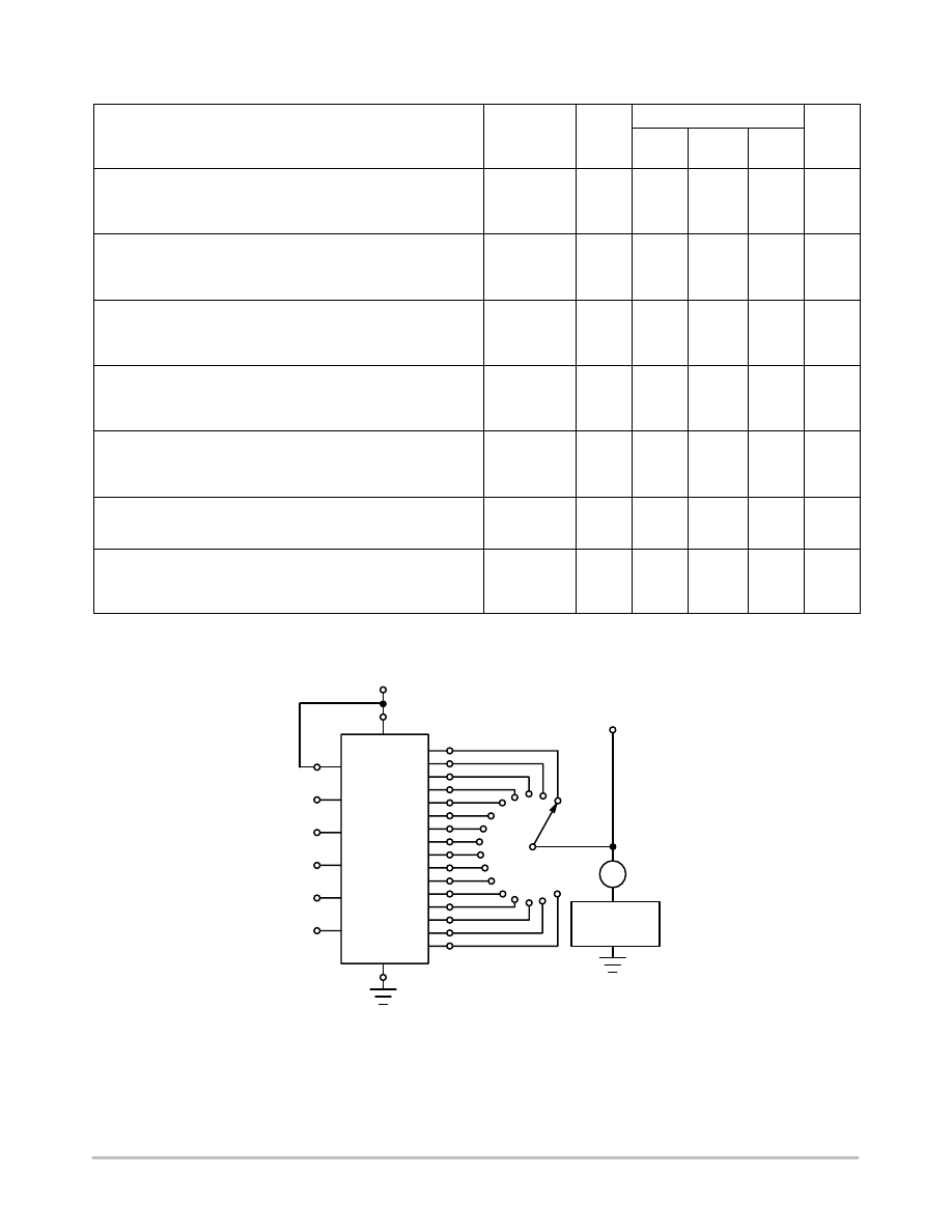
Figure 1. Drain Characteristics Test Circuit

EXTERNAL

POWER SUPPLY

V

SS

STROBE

INHIBIT

D1

D2

D3

D4

V

DD

V

DS

I

D

For MC14515B
1. For P

channel: Inhibit = V

DD

2. For N

channel: Inhibit = V

SS

2. 

and


D1

D4 constitute binary

2. 

code for “output


under test.”

For MC14514B
1. For P

channel: Inhibit = V

SS

1. 

and


D1

D4 constitute

1. 

binary code for “output

1. 

under test.”

2. For N

channel: Inhibit = V

DD

S15

S14

S13

S12

S11

S10

S9

S8

S7

S6

S5

S4

S3

S2

S1

S0

MC14514B, MC14515B

http://onsemi.com

5

Figure 2. Dynamic Power Dissipation Test Circuit and Waveform

PULSE

GENERATOR

C

L

C

L

V

DD

V

DD

V

SS

S0

S15

12

24

I

D

0.01 

m

F

CERAMIC

500

m

F

V

DD

V

SS

V

in

20 ns

20 ns

90%

10%

STROBE

D1
D2

D3
D4

INHIBIT

Figure 3. Switching Time Test Circuit and Waveforms

PROGRAMMABLE

PULSE

GENERATOR

V

DD

STROBE

INHIBIT

D1

D2

D3

D4

C

L

V

DD

V

SS

V

DD

V

SS

S0

S1

S15

V

SS

C

L

C

L

INPUT

OUTPUT

t

TLH

t

TLH

t

THL

t

THL

t

PHL

t

PLH

20 ns

OUTPUT S0

OUTPUT S1

OUTPUT S15

90%
50%
10%

90%

50%

10%

MC14514B, MC14515B

http://onsemi.com

6

LOGIC DIAGRAM

DA

TA

 1

2

DA

TA

 2

3

DA

TA

 3

21

DA

TA

 4

22

STROBE

1

INHIBIT

23

Q

Q

R

S

Q

Q

R

S

Q

Q

R

S

Q

Q

R

S

A

B

C

D

IN MC14515B ONL

Y

A

B

C

D

11

S

0

9S

1

10

S2

8S

3

7S

4

6S

5

5S

6

4S

7

18

S8

17

S9

20

S10

19

S1

1

14

S12

13

S13

16

S14

15

S15

AB

C

D

A

BC

D

AB

C

D

A

B

CD

AB

CD

A

BC

D

AB

C

D

A

B

C

D

AB

C

D

A

BC

D

AB

C

D

A

B

CD

AB

CD

A

BC

D

AB

C

D

MC14514B, MC14515B

http://onsemi.com

7

COMPLEX DATA ROUTING

Two MC14512 eight

channel data selectors are used here

with the MC14514B four

bit latch/decoder to effect a

complex data routing system. A total of 16 inputs from data
registers are selected and transferred via a 3

state data bus

to a data distributor for rearrangement and entry into 16
output registers. In this way sequential data can be re

routed

or intermixed according to patterns determined by data
select and distribution inputs.

Data is placed into the routing scheme via the eight inputs

on both MC14512 data selectors. One register is assigned to
each input. The signals on A0, A1, and A2 choose one of
eight inputs for transfer out to the 3

state data bus. A fourth

signal, labelled Dis, disables one of the MC14512 selectors,
assuring transfer of data from only one register.

In addition to a choice of input registers, 1 thru 16, the rate

of transfer of the sequential information can also be varied.
That is, if the MC14512 were addressed at a rate that is eight

times faster then the shift frequency of the input registers,
the most significant bit (MSB) from each register could be
selected for transfer to the data bus. Therefore, all of the
most significant bits from all of the registers can be
transferred to the data bus before the next most significant
bit is presented for transfer by the input registers.

Information from the 3

state bus is redistributed by the

MC14514B four

bit latch/decoder. Using the four

bit

address, D1 thru D4, the information on the inhibit line can
be transferred to the addressed output line to the desired
output registers, A thru P. This distribution of data bits to the
output registers can be made in many complex patterns. For
example, all of the most significant bits from the input
registers can be routed into output register A, all of the next
most significant bits into register B, etc. In this way
horizontal, vertical, or other methods of data slicing can be
implemented.

DATA ROUTING SYSTEM

INPUT

REGISTERS

DATA

TRANSFER

DATA

DISTRIBUTION

OUTPUT

REGISTERS

3-STATE

DATA BUS

REGISTER A

REGISTER P

REGISTER 1

REGISTER 8

REGISTER 9

REGISTER 16

DATA

SELECT

STROBE

INHIBIT

DIS

DIS

Q

Q

D1 D2 D3 D4

A0 A1 A2

A0 A1 A2

MC14514B

MC14512

MC14512

D0

D1
D2

D3
D4

D5
D6

D7

D0

D1
D2

D3
D4

D5

D6
D7

S15

S14

S13

S12

S11

S10

S9

S8

S7

S6

S5

S4

S3

S2

S1

S0

SOIC

24 WB

CASE 751E

04

ISSUE F

DATE 03 JUL 2012

SCALE 1:1

b

M

0.25

C

SEATING

PLANE

A1

M

L

DETAIL A

END VIEW

h

_

NOTES:

1. DIMENSIONING AND TOLERANCING PER ASME

Y14.5M, 1994.

2. CONTROLLING DIMENSION: MILLIMETERS.

3. DIMENSIONS b AND c APPLY TO THE FLAT

SECTION OF THE LEAD AND ARE MEASURED

BETWEEN 0.10 AND 0.25 FROM THE LEAD TIP.

4. DIMENSIONS D AND E1 DO NOT INCLUDE MOLD

FLASH, PROTRUSIONS OR GATE BURRS. MOLD

FLASH, PROTRUSIONS OR GATE BURRS SHALL

NOT EXCEED 0.15 mm PER SIDE. INTERLEAD

FLASH OR PROTRUSION SHALL NOT EXCEED

0.25 PER SIDE. DIMENSIONS D AND E1 ARE

DETERMINED AT DATUM H.

5. A1 IS DEFINED AS THE VERTICAL DISTANCE

FROM THE SEATING PLANE TO THE LOWEST

POINT ON THE PACKAGE BODY.

XXXXX = Specific Device Code
A

= Assembly Location

WL

= Wafer Lot

YY

= Year

WW

= Work Week

G

= Pb

Free Package

NOTE 3

PIN 1

12

1

24

13

TOP VIEW

DIM

MIN

MAX

MILLIMETERS

A

2.35

2.65

b

0.35

0.49

e

1.27 BSC

h

0.25

0.75

c

0.23

0.32

A1

0.13

0.29

L

0.41

0.90

M

0  

8  

_

_

D

E1

XXXXXXXXXXXXXX
XXXXXXXXXXXXXX
XXXXXXXXXXXXXX

AWLYYWWG

SIDE VIEW

*This information is generic. Please refer to

device data sheet for actual part marking.

Pb

Free indicator, “G” or microdot “ 

G

”,

may or may not be present.

GENERIC

MARKING DIAGRAM*

1

11.00

24X

0.52

24X

1.62

1.27

DIMENSIONS: MILLIMETERS

1

PITCH

*For additional information on our Pb

Free strategy and soldering

details, please download the ON Semiconductor Soldering and

Mounting Techniques Reference Manual, SOLDERRM/D.

SOLDERING FOOTPRINT*

E

10.30 BSC

RECOMMENDED

INDICATOR

A

B

0.25 C

24X

B

A

C

A

NOTE 5

x 45

c

NOTE 3

DETAIL A

C

H

D

15.25

15.54

E1

7.40

7.60

E

S

S

e

MECHANICAL CASE OUTLINE

PACKAGE DIMENSIONS

http://onsemi.com

1

 Semiconductor Components Industries, LLC, 2002

October, 2002 

 Rev. 0

Case Outline Number:

XXX

DOCUMENT NUMBER:

STATUS:

NEW STANDARD:

DESCRIPTION:

98ASB42344B

ON SEMICONDUCTOR STANDARD

SOIC

24 WB

Electronic versions are uncontrolled except when 
accessed directly from the Document Repository. Printed 
versions are uncontrolled except when stamped  
“CONTROLLED COPY” in red.

PAGE 1 OF 2

DOCUMENT NUMBER:

98ASB42344B

PAGE 2 OF 2

ISSUE

REVISION

DATE

F

REDREW TO JEDEC STANDARDS. ADDED SOLDER FOOTPRINT AND MARKING

DIAGRAM. REQ. BY I. CAMBALIZA.

03 JUL 2012

 Semiconductor Components Industries, LLC, 2012

July, 2012 

 Rev. F

Case Outline Number:

751E

ON Semiconductor

 and          are registered trademarks of Semiconductor Components Industries, LLC (SCILLC).  SCILLC reserves the right to make changes without further notice

to any products herein.  SCILLC makes no warranty, representation or guarantee regarding the suitability of its products for any particular purpose, nor does SCILLC assume any

liability arising out of the application or use of any product or circuit, and specifically disclaims any and all liability, including without limitation special, consequential or incidental

damages.  “Typical” parameters which may be provided in SCILLC data sheets and/or specifications can and do vary in different applications and actual performance may vary over

time.  All operating parameters, including “Typicals” must be validated for each customer application by customer’s technical experts.  SCILLC does not convey any license under

its patent rights nor the rights of others.  SCILLC products are not designed, intended, or authorized for use as components in systems intended for surgical implant into the body,

or other applications intended to support or sustain life, or for any other application in which the failure of the SCILLC product could create a situation where personal injury or death

may occur.  Should Buyer purchase or use SCILLC products for any such unintended or unauthorized application, Buyer shall indemnify and hold SCILLC and its officers, employees,

subsidiaries,  affiliates, and distributors harmless against all claims, costs, damages, and expenses, and reasonable attorney fees arising out of, directly or indirectly, any claim of

personal injury or death associated with such unintended or unauthorized use, even if such claim alleges that SCILLC was negligent regarding the design or manufacture of the part.

SCILLC is an Equal Opportunity/Affirmative Action Employer.  This literature is subject to all applicable copyright laws and is not for resale in any manner.

onsemi

 , and other names, marks, and brands are registered and/or common law trademarks of Semiconductor Components Industries, LLC dba “

onsemi

” or its affiliates

and/or subsidiaries in the United States and/or other countries. 

onsemi

 owns the rights to a number of patents, trademarks, copyrights, trade secrets, and other intellectual property.

A listing of 

onsemi

’s product/patent coverage may be accessed at 

www.onsemi.com/site/pdf/Patent

Marking.pdf

onsemi

 reserves the right to make changes at any time to any

products or information herein, without notice. The information herein is provided “as

is” and 

onsemi

 makes no warranty, representation or guarantee regarding the accuracy of the

information, product features, availability, functionality, or suitability of its products for any particular purpose, nor does 

onsemi

 assume any liability arising out of the application or use

of any product or circuit, and specifically disclaims any and all liability, including without limitation special, consequential or incidental damages. Buyer is responsible for its products

and applications using 

onsemi

 products, including compliance with all laws, regulations and safety requirements or standards, regardless of any support or applications information

provided by 

onsemi

. “Typical” parameters which may be provided in 

onsemi

 data sheets and/or specifications can and do vary in different applications and actual performance may

vary over time. All operating parameters, including “Typicals” must be validated for each customer application by customer’s technical experts. 

onsemi

 does not convey any license

under any of its intellectual property rights nor the rights of others. 

onsemi

 products are not designed, intended, or authorized for use as a critical component in life support systems

or any FDA Class 3 medical devices or medical devices with a same or similar classification in a foreign jurisdiction or any devices intended for implantation in the human body. Should

Buyer purchase or use 

onsemi

 products for any such unintended or unauthorized application, Buyer shall indemnify and hold 

onsemi

 and its officers, employees, subsidiaries, affiliates,

and distributors harmless against all claims, costs, damages, and expenses, and reasonable attorney fees arising out of, directly or indirectly, any claim of personal injury or death

associated with such unintended or unauthorized use, even if such claim alleges that 

onsemi

 was negligent regarding the design or manufacture of the part. 

onsemi

 is an Equal

Opportunity/Affirmative Action Employer. This literature is subject to all applicable copyright laws and is not for resale in any manner.

PUBLICATION ORDERING INFORMATION

TECHNICAL SUPPORT

North American Technical Support:

Voice Mail: 1 800

282

9855 Toll Free USA/Canada

Phone: 011 421 33 790 2910

LITERATURE FULFILLMENT

:

Email Requests to:

 orderlit@onsemi.com

onsemi Website:

 www.onsemi.com

Europe, Middle East and Africa Technical Support:

Phone: 00421 33 790 2910

For additional information, please contact your local Sales Representative

Mouser Electronics


Authorized Distributor


Click to View Pricing, Inventory, Delivery & Lifecycle Information:


onsemi


MC14514BCP


MC14514BCPG


MC14514BDWR2


MC14514BDWR2G


MC14515BCP


MC14515BCPG


MC14515BDWR2


MC14515BDWR2G


NLV14515BDWR2G


NLV14514BDWR2G

WT8045

Synchronous   Signal   Discriminator   and

Power Saving Detector for Green Monitor





Weltrend  Semiconductor,  Inc.

2F., No. 24, Industry E. 9th Rd.

Science-Based Industrial Park

Hsin-Chu, Taiwan, R.O.C.

Tel:  886-35-780241

Fax: 886-35-770419

1

May 4, 1995

DESCRIPTION

The WT8045 is a silicon monolithic circuit designed for synchronous signal processing and power
saving detection of multi-sync display monitors, which can cope with many kinds of PC's and
workstations.

It can be applied to display monitors supporting standard IBM VGA, VESA super VGA and IBM
8514/A video modes. It can also be used in other high-end display monitors supporting non-standard
video modes with user-defined horizontal/vertical frequency ranges.

The WT8045 incorporates many functional circuits, including horizontal/vertical frequency
discrimination, display mode selection, and synchronous pulse polarity and power saving detection,
into this single chip IC.

WT8045 is more convenient for you to shrink the PC board size and to reduce the material and labor
cost with fewer components.

FEATURES

Accepting two separated H&V synchronous signals with positive/ negative polarity.

Support VESA VGA (640X480, 640X400, 640X350), VESA SVGA (800X600), European
SVGA (800X600), VESA new SVGA (800X600), XGA (1024X768) and 1280x1024.

Capable of processing horizontal frequency between 25KHZ to 80KHZ.

Standard IBM video mode control outputs (1024X768, 640X480, 640X400, 640X350).

Five non-standard horizontal frequency control outputs in  predefined frequency range.

Power saving mode - It can detect the conditions of monitor to decide which one will be selected
as following: ON/STANDBY/SUSPEND/OFF mode.

Fixed polarity outputs on both horizontal and vertical synchronous signals.

WT8045

Synchronous   Signal   Discriminator   and

Power Saving Detector for Green Monitor





Weltrend  Semiconductor,  Inc.

2F., No. 24, Industry E. 9th Rd.

Science-Based Industrial Park

Hsin-Chu, Taiwan, R.O.C.

Tel:  886-35-780241

Fax: 886-35-770419

2

Power supply voltage: DC 5 volts; but for those pins with open-drain structure, such like the
mode select control output and frequency discrimination control output pins, can be connected to
12 volts through pull-high resistor.

APPLICATION

Auto size control for Multi-Sync Display Monitors

ORDERING INFORMATION

Part No.

Package

Note

WT8045N24P1

P-DIP 24L

V * 128

WT8045N24P3

P-DIP 24L

Without Mute

WT8045N24P4

P-DIP 24L

Without Mute

WT8045N24P5

P-DIP 24L

V * 1

WT8045N24P6

P-DIP 24L

With Mute

WT8045N24P7

P-DIP 24L

Without Mute

WT8045N24P8

P-DIP 24L

With Mute

WT8045N28P1

P-DIP 28L (skinny)

V * 128 Without Mute

WT8045N28P2

P-DIP 28L (skinny)

V * 128 Without Mute

WT8045N28P3

P-DIP 28L (skinny)

V * 1 Without Mute

WT8045N28P4

P-DIP 28L (skinny)

V * 128 With Mute

WT8045N28P5

P-DIP 28L (skinny)

V * 1 With Mute

WT8045N28P6

P-DIP 28L (skinny)

V * 1 Without Mute

WT8045N28P7

P-DIP 28L (skinny)

V * 128 With Mute

WT8045N28P8

P-DIP 28L (skinny)

V * 1 With Mute

WT8045N32

P-DIP 32L

--

WT8045

Synchronous   Signal   Discriminator   and

Power Saving Detector for Green Monitor





Weltrend  Semiconductor,  Inc.

2F., No. 24, Industry E. 9th Rd.

Science-Based Industrial Park

Hsin-Chu, Taiwan, R.O.C.

Tel:  886-35-780241

Fax: 886-35-770419

3

PIN CONFIGURATION

1

2

3

4

5

6

7

8

9

10

11

12

14

15

16

OSCin

HSin

OSCout

VSin

H_out

V_out

VDD

WT8045N24P1

F43.5K

F36.2K

QV128

QVRC

Vss

QHRC

QH

640x400

640x480

800x600(48K)

17

18

19

20

21

22

23

24

800x600(37.5K)

800x600(35.2K)

1024x768(56.5K)

1024x768 (I)

F33K

640x350

1024x768 (NI)

13


1

2

3

4

5

6

7

8

9

10

11

12

13

14

15

16

OSCin

HSin

OSCout

VSin

H_out

V_out

VDD

WT8045N24P3

F43.5K

F36.2K

PM3

PM1

Vss

QHRC

QH

640x400

640x480

800x600(48K)

17

18

19

20

21

22

23

24

800x600(37.5K)

800x600(35.2K)

1024x768(56.5K)

1024x768 (I)

F33K

640x350

1024x768 (NI)

1

2

3

4

5

6

7

8

9

10

11

12

13

14

15

16

OSCin

HSin

OSCout

VSin

Hout

Vout

VDD

WT8045N24P4

F36.2K

F33K

NC

NC

VSS

PM1

PM2

PM3

NC

640x350
(31.5K/37.5K)

640x480
(37.5K/72Hz)

640x400(31.5K)

17

18

19

20

21

22

23

24

640x480(31.5K)

800x600(35.2K)

NC

800x600(37.5K)

1024x768 (I)


1

2

3

4

5

6

7

8

9

10

11

12

14

15

16

OSCin

HSin

OSCout

VSin

H_out

V_out

VDD

WT8045N24P5

F43.5K

F36.2K

QV1

QVRC

Vss

QHRC

QH

640x400

640x480

800x600(48K)

17

18

19

20

21

22

23

24

800x600(37.5K)

800x600(35.2K)

1024x768(56.5K)

1024x768 (I)

F33K

640x350

1024x768 (NI)

13

WT8045

Synchronous   Signal   Discriminator   and

Power Saving Detector for Green Monitor





Weltrend  Semiconductor,  Inc.

2F., No. 24, Industry E. 9th Rd.

Science-Based Industrial Park

Hsin-Chu, Taiwan, R.O.C.

Tel:  886-35-780241

Fax: 886-35-770419

4

1

2

3

4

5

6

7

8

9

10

11

12

13

14

15

16

OSCin

HSin

OSCout

VSin

H_out

V_out

VDD

WT8045N24P6

F43.5K

F36.2K

PM3

Mute

Vss

QHRC

QH

640x400

640x480

800x600(48K)

17

18

19

20

21

22

23

24

800x600(37.5K)

800x600(35.2K)

1024x768(56.5K)

1024x768 (I)

F33K

640x350

1024x768 (NI)

1

2

3

4

5

6

7

8

9

10

11

12

13

14

15

16

OSCin

HSin

OSCout

VSin

H_out

V_out

VDD

WT8045N24P7

F43.5K

F36.2K

PM1

P52K

Vss

PM2

PM3

640x400

640x480

800x600(48K)

17

18

19

20

21

22

23

24

800x600(37.5K)

800x600(35.2K)

1024x768(56.5K)

1024x768 (I)

F33K

640x350

1024x768 (NI)

1

2

3

4

5

6

7

8

9

10

11

12

13

14

15

16

OSCin

HSin

OSCout

VSin

H_out

V_out

VDD

WT8045N24P8

F43.5K

F36.2K

PM1+PM2

P52K

Vss

Mute

PM3

640x400

640x480

800x600(48K)

17

18

19

20

21

22

23

24

800x600(37.5K)

800x600(35.2K)

1024x768(56.5K)

1024x768 (I)

F33K

640x350

1024x768 (NI)

1

2

3

4

5

6

7

8

9

10

11

12

13

14

15

16

OSCin

HSin

OSCout

VSin

H_out

V_out

VDD

WT8045N32

F43.5K

F36.2K

PM3

PM1

Vss

QHRC

640x400

640x480

800x600(48K)

17

18

19

20

21

22

31

32

800x600(37.5K)

800x600(35.2K)

1024x768(56.5K)

1024x768 (I)

F33K

640x350

1024x768 (NI)

30

29

28

27

26

25

24

23

QV128

QVRC

SELPIN

QH

-QH

F52K

F60K

PM2

1280x1024(64K)

WT8045

Synchronous   Signal   Discriminator   and

Power Saving Detector for Green Monitor





Weltrend  Semiconductor,  Inc.

2F., No. 24, Industry E. 9th Rd.

Science-Based Industrial Park

Hsin-Chu, Taiwan, R.O.C.

Tel:  886-35-780241

Fax: 886-35-770419

5

1

2

3

4

5

6

7

8

9

10

11

12

13

14

15

16

OSCin

HSin

OSCout

VSin

H_out

V_out

VDD

WT8045N28P1

F43.5K

F36.2K

PM3

PM1

Vss

QHRC

640x400

640x480

800x600(48K)

17

18

19

20

21

22

800x600(37.5K)

800x600(35.2K)

1024x768(56.5K)

1024x768 (I)

F33K

640x350

1024x768 (NI)

28

27

26

25

24

23

QV128

QVRC

QH

F52K

PM2

1

2

3

4

5

6

7

8

9

10

11

12

13

14

15

16

OSCin

HSin

OSCout

VSin

H_out

V_out

VDD

WT8045N28P3

F43.5K

F36.2K

PM3

PM1

Vss

QHRC

640x400

640x480

800x600(48K)

17

18

19

20

21

22

800x600(37.5K)

800x600(35.2K)

1024x768(56.5K)

1024x768 (I)

F33K

640x350

1024x768 (NI)

28

27

26

25

24

23

QV1

QVRC

QH

F52K

PM2

WT8045

Synchronous   Signal   Discriminator   and

Power Saving Detector for Green Monitor





Weltrend  Semiconductor,  Inc.

2F., No. 24, Industry E. 9th Rd.

Science-Based Industrial Park

Hsin-Chu, Taiwan, R.O.C.

Tel:  886-35-780241

Fax: 886-35-770419

6

1

2

3

4

5

6

7

8

9

10

11

12

13

14

15

16

OSCin

HSin

OSCout

VSin

H_out

V_out

VDD

WT8045N28P4

F43.5K

F36.2K

PM3

PM1 
+PM2

Vss

QHRC

640x400

640x480

800x600(48K)

17

18

19

20

21

22

800x600(37.5K)

800x600(35.2K)

1024x768(56.5K)

1024x768 (I)

F33K

640x350

1024x768 (NI)

28

27

26

25

24

23

QV128

QVRC

QH

F52K

Mute


1

2

3

4

5

6

7

8

9

10

11

12

13

14

15

16

OSCin

HSin

OSCout

VSin

H_out

V_out

VDD

WT8045N28P5

F43.5K

F36.2K

PM3

PM1 
+PM2

Vss

QHRC

640x400

640x480

800x600(48K)

17

18

19

20

21

22

800x600(37.5K)

800x600(35.2K)

1024x768(56.5K)

1024x768 (I)

F33K

640x350

1024x768 (NI)

28

27

26

25

24

23

QV1

QVRC

QH

F52K

Mute

Note: The Hout and Vout pin of N28P1, N28P3, N28P4 and N28P5 are negative pulse.

WT8045

Synchronous   Signal   Discriminator   and

Power Saving Detector for Green Monitor





Weltrend  Semiconductor,  Inc.

2F., No. 24, Industry E. 9th Rd.

Science-Based Industrial Park

Hsin-Chu, Taiwan, R.O.C.

Tel:  886-35-780241

Fax: 886-35-770419

7

ABSOLUTE MAXIMUM RATINGS

ITEM

SYMBOL

VALUE

UNIT

Digital Supply Voltage

VDD

5.5

V

Horizontal Sync. Input Voltage

VHS

VDD(5)+0.3

VPP

Vertical Sync. Input Voltage

VVS

VDD(5)+0.3

VPP

Power Dissipation

PD

300

mW

Operating Temperature Range

TOPT

0

¡ ã

70

¢ J

Storage Temperature Range

TSTG

-40

¡ ã

125

¢ J

RECOMMENDED OPERATING CONDITIONS

ITEM

SYMBOL

MIN.

TYP.

MAX.

UNIT

Digital Supply Voltage

VDD(5)

4.5

5

5.5

V

Supply Current (Standby)

IP

13

mA

Synchronous Input Voltage Low

VIL

0.8

VPP

Synchronous Input Voltage High

VIH

2.4

4

5.5

VPP

Horizontal Synchronous Frequency
 Range

FH

25

¡ Ð

80

(for N32)

KHz

Vertical Synchronous Frequency
 Range

FV

50

¡ Ð

120

Hz

Crystal Clock Frequency

FCLK

3.5764

3.58

3.5836

MHz

Open Drain Pull High Voltage

VOH

12

V

Resistance of Monostable for Hsin

RH

10

100

K

£ [

Capacitance of Monostable for Hsin

CH

¡ Ð

100

¡ Ð

pF

Resistance of Monostable for Vsin

RV

10

500

K

£ [

Capacitance of Monostable for Vsin

CV

¡ Ð

100

¡ Ð

pF

WT8045

Synchronous   Signal   Discriminator   and

Power Saving Detector for Green Monitor





Weltrend  Semiconductor,  Inc.

2F., No. 24, Industry E. 9th Rd.

Science-Based Industrial Park

Hsin-Chu, Taiwan, R.O.C.

Tel:  886-35-780241

Fax: 886-35-770419

8

ELECTRICAL CHARACTERISTICS

(VDD=5V, TOPT=25

°

C, Crystal=3.58MHz)

ITEM

SYMBOL

MIN.

TYP.

MAX.

UNIT

F33K

32.9

¡ Ð

33.1

KHz

Discrimination of H.

F36.2K

36.1

¡ Ð

36.3

KHz

Synchronous Frequency

F43.5K

43.4

43.6

KHz

F52K

51.9

¡ Ð

52.1

KHz

F60K

59.9

¡ Ð

60.1

KHz

Output Low (H-out, V-out),
when IOL = 4mA

VOL1

0.4

VPP

Output High (H-out, V-out),
when IOH = -400

£ g

A

VOH1

2.4

VPP

Open Drain Output Low
when IOL = 6mA

VOL2

0.4

VPP

Output Sink Current (H-out, V-out)
when VOL1 = 0.4V

IOL1

4

mA

Output Drive Current (H-out, V-out)
when VOH1 = 2.4V

¡ W

IOH1

¡ W

400

£ g

A

Open Drain Sink Current
when VOL2 = 0.4V

IOL2

10

mA

Open Drain Sink Current
when VOL2 = 5V

IOL2

40

mA


содержание      ..     8      9      10      11     ..